1
Digital Platform Scale
1WMPD4000041D
HV-15KGL
HV-60KGL
HV-200KGL
HV-15KGV
HV-60KGV
HV-200KGV
HW-10KGL
HW-60KGL
HW-100KGL
HW-200KGL
HW-10KGV
HW-60KGV
HW-100KGV
HW-200KGV
HW-300KGL4
HW-600KGL4
HW-600KGL3
HW-1200KGL3
HW-300KGV4
HW-600KGV4
HW-600KGV3
HW-1200KGV3
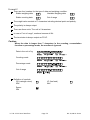
This is a hazard alert mark.
This mark informs you about the operation of the product.
Note This manual is subject to change without notice at any time to improve the product.
No part of this manual may be photocopied, reproduced, or translated into another
language without the prior written consent of A&D Company, Limited.
Product specifications are subject to change without any obligation on the part of the
manufacturer.
Contents
1.
Compliance ................................................................................................ 3
1.1. Compliance with FCC rules.................................................................... 3
2.
Outline and Features ................................................................................. 4
3.
Unpacking .................................................................................................. 5
3.1. Accessories and Options List................................................................. 7
4.
Precautions ................................................................................................ 9
4.1. Installing the Scale ................................................................................. 9
4.2. Operating the Scale ............................................................................... 9
4.3. Storing the Scale.................................................................................... 9
5.
Installing the Scale................................................................................... 10
5.1. Setting up the Scale............................................................................. 10
5.1.1. Procedure A................................................................................. 10
5.1.2. Procedure B................................................................................. 11
5.1.3. Procedure C................................................................................. 12
5.2. Installing the Batteries for Type L ......................................................... 13
5.3. Removing the Pole............................................................................... 14
5.3.1. Procedure A................................................................................. 14
5.3.2. Procedure B................................................................................. 15
5.4. Grounding the scale............................................................................. 16
6.
Description of Each Part .......................................................................... 17
6.1. Display and Symbols ........................................................................... 19
6.2. Keys ..................................................................................................... 21
7.
Basic Operation ....................................................................................... 23
7.1. Turning the Scale on/off and Weighing ................................................ 23
7.1.1. Type V or Type L with AC Adapter .............................................. 23
7.1.2. Type L with Batteries ................................................................... 24
7.2. Tare (And Net Display) ......................................................................... 25
7.2.1. Tare Input by Weighing................................................................ 25
7.2.2. Digital Input (Preset Tare)............................................................ 25
7.3. Weighing Range for the HV-G Series................................................... 26
7.4. Mode Key (Changing Unit and Mode).................................................. 27
8.
Counting Mode......................................................................................... 29
8.1. Storing a Unit Mass.............................................................................. 29
8.2. Counting the Number of Articles .......................................................... 30
9.
Percentage Mode..................................................................................... 31
9.1. Storing a 100% Mass ........................................................................... 31
9.2. Reading the Percentage ...................................................................... 32
10.
Accumulation Function ........................................................................ 33
10.1. Preparation (Setting Parameters) ........................................................ 34
10.2. Operation and Performance (Examples).............................................. 35
HV-G/HW-G Series
Page 1
11.
Upper/Lower Comparator Function...................................................... 36
11.1. Preparation (Setting Parameters) ........................................................ 37
11.2. Operation and Performance (Examples).............................................. 39
12.
Full/Dribble Batch Function.................................................................. 40
12.1. Preparation (Setting Parameters) ........................................................ 42
13.
Simple Batch Function......................................................................... 44
13.1. Preparation (Setting Parameters) ........................................................ 45
13.2. Operation and Performance (Examples).............................................. 46
14.
Calibration (Adjusting the Scale).......................................................... 47
14.1. Gravity Acceleration Table.................................................................... 48
14.2. Complete Calibration Procedure .......................................................... 49
14.2.1. Gravity Acceleration Correction ................................................. 49
14.2.2. Preparation ................................................................................ 49
14.2.3. Calibration of the Zero Point ........................................................ 50
14.2.4. Span Calibration ........................................................................ 50
15.
Function Table ..................................................................................... 51
15.1. Parameter Setting Procedure............................................................... 51
15.2. Parameter List...................................................................................... 52
16.
RS-232C Serial Interface..................................................................... 56
16.1. Data Format ......................................................................................... 57
16.2. Stream Mode........................................................................................ 59
16.2.1. Preparation and Performance (Examples)................................. 59
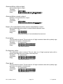
16.3. Command Mode .................................................................................. 60
16.3.1. Command List............................................................................ 60
16.3.2. Example of Setting Parameters ................................................. 63
17.
Options ................................................................................................ 64
17.1. Extension Load Cell Cable (OP-02) ..................................................... 64
17.2. RS-232C/ Relay Output/ Buzzer (OP-03) ............................................ 66
17.3. RS-422/ RS-485 / Relay Output (OP-04) ............................................. 68
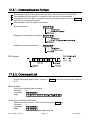
17.3.1. Communication Format.............................................................. 71
17.3.2. Command List............................................................................ 71
17.4. Built-in Printer for Type V (OP-06) ....................................................... 74
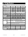
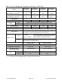
18.
Specifications ...................................................................................... 76
19.
Maintenance ........................................................................................ 81
19.1. Check Points Before Calling Maintenance Service ...................................... 81
19.1.1. Repair ........................................................................................ 81
Page 2
HV-G/HW-G Series
1. Compliance
1.1.
Compliance with FCC rules
Please note that this equipment generates, uses and can radiate radio frequency
energy. This equipment has been tested and has been found to comply with the limits
of a Class A computing device pursuant to Subpart J of Part 15 of FCC rules. These
rules are designed to provide reasonable protection against interference when this
equipment is operated in a commercial environment. If this unit is operated in a
residential area it might cause some interference and under these circumstances the
user would be required to take, at his own expense, whatever measures are
necessary to eliminate the interference.
(FCC = Federal Communications Commission in the U.S.A.)
HV-G/HW-G Series
Page 3
1. Compliance
2. Outline and Features
The HV-G series are platform scales with 1/3000 resolution, and have the triple
weighing range function to select the weighing range.
The HW-G series come with two types of resolution;
1/6000 : HW-300KGL4, HW-300KGV4, HW-600KGL4, HW-600KGV4, HW-600KGL3,
HW-600KGV3, HW-1200KGL3 and HW-1200KGV3.
1/10000 : Other models
Type L scales use a Liquid Crystal Display (LCD) and use batteries or an AC adapter
as a power source.
Type V scales use a fluorescent display so it can be read in dim light. This type is
directly powered from the AC power line.
Using the standard RS-232C serial interface, data can be output to a printer, and the
scale can be controlled or can be set by a command from a personal computer.
The counting mode converts the total mass value (total weight) of articles to be
counted, to a count, when each article has the same mass value.
The scales can display the unit of percentage.
The accumulation function (up to 6 digits) accumulates each weight value and counts
the number of times articles are weighed.
The comparator function compares the displayed weight value with the upper limit
value (HI) and the lower limit value (LO) and displays the result. The result can be
output by a buzzer if option OP-03 is installed.
The simple batch function or full/dribble batch function can be used for filling up to a
target mass value. The status of a weight value can be output if option OP-03 or
OP-04 is installed. The outputs are zero band, preliminary and final.
The optional RS-422/RS-485 serial interface can control up to 16 scales from a
computer, when this option (OP-04) is installed instead of an RS-232C serial
interface.
Type V scales can be equipped with option OP-06, a built-in impact dot matrix printer.
The following parameters are stored in the scale even if the power is removed.
Unit mass of counting mode
100% mass of percentage mode
Total count and total mass of accumulation function
Upper limit value and lower limit value of upper / lower comparator function,
Final value, preliminary value and zero band of full / dribble batch function or
Final value, preliminary value and zero band of simple batch function
Calibration data
Parameters of the function table (f1 to f17)
2. Outline and Features
Page 4
HV-G/HW-G Series
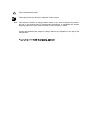
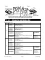
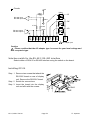
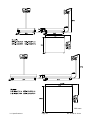
3. Unpacking
Models
HV-15KGL
HV-15KGV
HW-10KGL
HW-10KGV
Models
HV-60KGL
HW-60KGL
Display Unit
HV-60KGV
HW-60KGV
Display Unit
Pan
Pan
Base Unit
Models
HV-200KGL HV-200KGV
HW-100KGL HW-100KGV
HW-200KGL HW-200KGV
Display Unit
Base Unit
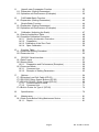
Caution
Do not pull the load cell cable.
Accessories
Refer to "Accessries List" on page 7.
Accessories supplied depend on the scale
model.
Pan
AC adapter
Please confirm that
the AC adapter type
is correct for your
local voltage and
receptacle type.
Base Unit
Display unit cover
14:3003217
Caution
Do not pull the load cell cable.
Allen wrench
HV-G/HW-G Series
Page 5
3. Unpacking
Models
HW-300KGL4
HW-300KGV4
HW-600KGL4
HW-600KGV4
Models
HW-600KGL3
HW-600KGV3
HW-1200KGL3
HW-1200KGV3
Display Unit
Display Unit
Pan
Pan
Base Unit
Base Unit
Caution
Do not pull the
load cell cable.
Caution
Do not pull the
load cell cable.
Accessories
Refer to "Accessories List" on the next page. Accessories supplied depend on the scale model.
Display unit cover
14:3003217
Cable clamp
(2 pcs)
AC adapter
Please confirm that
the AC adapter type
is correct for your
local voltage and
receptacle type.
Phillips screwdriver
Set of Allen screws
for pole installation
(with Allen wrench)
Wrench for leveling
foot adjustment
Cable tie
(1 pc)
HW-600KGL3/600KGV3
1200KGL3/1200KGV3
5 mm screw for pan installation
4 mm screw for
display unit installation (4 pcs) HW-300KGL4/300KGV4
600KGL4/600KGV4
(2 pcs)
3. Unpacking
Page 6
HV-G/HW-G Series
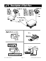
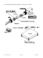
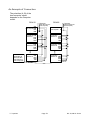
Type V
Type L
LCD
Fluorescent display
Main power cord
AC adapter
Option built-in printer
Batteries
(Not included)
Please confirm that the main power type or AC adapter
type is correct for your local voltage and receptacle type.
3.1.
Accessories and Options List
Accessories List
Type
V
Models
HV-15KGV
HW-10KGV
Display unit cover (1)
Instruction manual (1)
HV-60KGV
HV-200KGV
HW-60KGV
HW-100KGV
HW-200KGV
Display unit cover (1)
Allen wrench (1)
Instruction manual (1)
HW-300KGV4
HW-600KGV4
HW-600KGV3
HW-1200KGV3
L
Display unit cover (1)
AC Adapter (1)
Instruction manual (1)
HV-60KGL
HV-200KGL
HW-60KGL
HW-100KGL
HW-200KGL
Display unit cover (1)
Allen wrench (1)
AC Adapter (1)
Instruction manual (1)
HW-600KGL3
HW-1200KGL3
Note
Display unit cover (1)
Phillips screwdriver (1)
Cable clamp (2)
Instruction manual (1)
Set of Allen screws for pole installation with Allen
wrench (1)
Cable tie (1)
4 mm screw for display unit installation (2)
HV-15KGL
HW-10KGL
HW-300KGL4
HW-600KGL4
A
Accessories (Quantity)
Display unit cover (1)
Phillips screwdriver (1)
AC Adapter (1)
Cable clamp (2)
Instruction manual (1)
Set of Allen screws for pole installation with Allen
wrench (1)
Cable tie (1)
4 mm screw for display unit installation (2)
5 mm screw for
pan installation
(4)
Wrench for
leveling foot
adjustment (1)
A
A
A
5 mm screw for
pan installation
(4)
Wrench for
leveling foot
adjustment (1)
The AC adapter may not be provided for some areas.
HV-G/HW-G Series
Page 7
A
A
A
A
3. Unpacking
A
A
A
A
Options List
OP-03
Order code / Option name
Extension load cell cable (For weighing
capacity of 10 kg to 200 kg)
Extension load cell cable (For weighing
capacity of 300 kg to 1200 kg)
RS-232C interface/ Relay output/ Buzzer
OP-04
RS-422/485 interface/ Relay output
OP-06
Built-in printer for type V
OP-02
Accessories
Tapping screw M4x10
Connector JA:TCP0586
Connector
TM:BLA9
AC adapter
Paper
Ink ribbon
PP156
ERC-05
OP-11
OP-13
OP-14
OP-15
Wall mounting kit
Roller conveyor for HV-200KG, HW-100KG and HW-200KG
Roller conveyor for HV-60KG and HW-60KG
Display unit stand (The display is not included)
For HW-300KGL4, HW-300KGV4, HW-600KGL4 and HW-600KGV4
For HW-600KGL3, HW-600KGV3, HW-1200KGL3 and HW-1200KGV3
OP-16-3
Wheel for HW-600KGL3, HW-600KGV3, HW-1200KGL3 and HW-1200KGV3
OP-16-4
Wheel for HW-300KGL4, HW-300KGV4, HW-600KGL4 and HW-600KGV4
OP-17
Stainless steel cover for HW-600KGL3, HW-600KGV3, HW-1200KGL3
and HW-1200KGV3
OP-18-3
Roller conveyor for HW-600KGL3, HW-600KGV3, HW-1200KGL3 and
HW-1200KGV3
OP-18-4
Roller conveyor for HW-300KGL4, HW-300KGV4, HW-600KGL4 and
HW-600KGV4
AX-KO577A-200 RS-232C cable, D-sub 25 pin, 2 m
AX-KO1786-200 RS-232C cable, D-sub 9 pin, 2 m
AX-KO577A-200
A
A
A
A
A
A
A
A
A
A
A
A
A
A
A
A
A
A
AX-KO1786-200
Note OP-16 and OP-17 are factory-installed.
For handling OPs-11, 13, 14, 15, 16, 17 and 18, refer to the relevant option manual.
Consumables
AX-PP156-S
AX-ERC-05-S
3. Unpacking
A
A
Special roll paper (10 rolls)
Ink ribbon (5 ink ribbons)
Page 8
HV-G/HW-G Series
4. Precautions
4.1.
Installing the Scale
Consider the following conditions to get the most from your scale.
Install the scale where the temperature and relative humidity is stable, there is no draft
and a stable power source is available.
Install the scale on a solid and level surface.
Do not install the scale in direct sunlight.
Do not install the scale near heaters or air conditioners.
Do not install the scale where there is flammable or corrosive gas present.
Do not install the scale near equipment which produces magnetic fields.
Do not install the scale where there is apt to be static electricity, in a place where the
relative humidity is lower than 45% RH. Plastic and isolators are apt to be charged with
static electricity.
The display unit is not water resistant. Use the display unit cover to avoid damage.
Do not use an unstable power source.
4.2.
Operating the Scale
Periodically ensure that the weight value is correct.
Calibrate the scale before using and after moving it to another location.
Do not place anything on the pan which exceeds the weighing capacity.
Do not drop anything upon the pan.
Do not use a sharp instrument such as a pencil to press the keys. Press the keys
gently using your finger.
Pressing the ZERO key before each weighing is recommended to prevent possible
error.
Replace the used batteries with six new ones when the
mark is displayed.
Battery is of type D, Mono, R20P, R20PU or LR20.
4.3.
Storing the Scale
Do not disassemble the scale.
Do not use solvents to clean the scale. Wipe it with a dry lint free cloth or a lint free
cloth which is moistened with warm water and a mild detergent.
The base unit can be cleaned with gentle running tap water. Do not scratch the base
unit with a brash. Allow the unit to dry before using.
Protect the display unit from dust and water.
Remove the batteries from the display unit when the scale is not to be used for a long
time. If you leave the batteries installed, they may leak and damage the scale.
HV-G/HW-G Series
Page 9
4. Caution
5. Installing the Scale
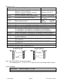
5.1.
Setting up the Scale
The setup procedure depends on the scale model. Refer to the table below.
Models
Refer to
HV-15KGL/HV-15KGV/HV-60KGL/HV-60KGV/HV-200KGL/HV-200KGV/HW-10KGL
HW-10KGV/HW-60KGL/HW-60KGV/HW-100KGL/HW-100KGV/HW-200KGL/HW-200KGV
HW-300KGL4/HW-300KGV4/ HW-600KGL4/HW-600KGV4
HW-600KGL3/HW-600KGV3/ HW-1200KGL3/HW-1200KGV3
Procedure A
Procedure B
Procedure C
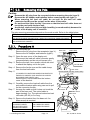
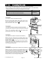
5.1.1. Procedure A
HV-15KGL/HV-15KGV/HV-60KGL/HV-60KGV/HV-200KGL/HV-200KGV/HW-10KGL
HW-10KGV/HW-60KGL/HW-60KGV/HW-100KGL/HW-100KGV/HW-200KGL/HW-200KGV
This procedure includes all of the steps for installing
the scales described above. Therefore, there may
be some unnecessary steps for some models.
Step 1 Take the base unit and pole out, taking care
not to pull on the load cell cable.
Step 2 Place the pan on the base unit.
Step 3 Attach the pole to the bracket of the base
unit, while using care not to damage the load
cell cable.
Insert the remainder of the load cell cable
into the pole.
Affix the pole to the bracket using two Allen
screws.
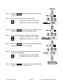
Step 4 Select a place for installing the scale. Refer
to "4.1. Installing the Scale” .
Step 5 Adjust the level of the base unit using the
bubble spirit level and the leveling feet.
Step 6 Press the caps at the pole top from both
sides and adjust the angle of the display unit.
Step 7 Check the weighing accuracy. If the scale
needs calibration, refer to "14. Calibration".
5. Installing the Scale
Page 10
HV-G/HW-G Series
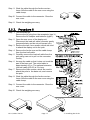
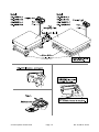
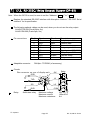
5.1.2. Procedure B
HW-300KGL4/HW-300KGV4
HW-600KGL4/HW-600KGV4
Note The display unit, the pole and the base unit
are connected using cables. So, use care
when lifting the display unit.
Step 1 Take the base unit, pole and display unit
out, taking care not to pull on the load cell
cable.
Step 2 Remove the pan.
Step 3 Attach the pole to the display unit with two
4 mm screws.
Attach the cable clamps on the back of the
pole to organize the cables.
Step 4 Attach the pole to the base unit with four
Allen screws and plain washers, while
using care not to damage the load cell
cable.
Using the cable tie, collect and bundle the
remainder of the load cell cable.
Replace the pan.
Step 5 Affix the pan using the 5 mm screws.
Step 6 Select a place for installing the scale.
Refer to "4.1. Installing the Scale" .
Step 7 Adjust the level of the base unit using the
bubble spirit level and the leveling feet.
Step 8 Press the caps at the pole top from both
sides and adjust the angle of the display
unit.
Step 9 Check the weighing accuracy. If the scale
needs
calibration,
refer
to
"14.
Calibration".
HV-G/HW-G Series
Page 11
5. Installing the Scale
5.1.3. Procedure C
HW-600KGL3/HW-600KGV3
HW-1200KGL3/HW-1200KGV3
Note The display unit, the pole and the base unit
are connected using cables. So, use care
when lifting the display unit.
Step 1 Take the scale out.
The pole, the display unit and the
accessories are found inside the base
unit.
Step 2 Remove the pan and the accessories.
Step 3 Attach the pole to the display unit with two
4 mm screws.
Attach the cable clamps on the back of the
pole to organize the cables.
Step 4 Attach the pole to the base unit with four
Allen screws and plain washers, while
using care not to damage the load cell
cable.
Using the cable tie, collect and bundle the
remainder of the load cell cable.
Step 5 Replace the pan in the direction as shown
in the illustration.
Step 6 Select a place for installing the scale.
Refer to "4.1. Installing the Scale" .
Step 7 Adjust the level of the base unit using the
leveling feet.
Note
A bubble spirit level is not provided. (The
load values on the four corners are
added.)
Step 8 Press the caps at the pole top from both
sides and adjust the angle of the display
unit.
Step 9 Check the weighing accuracy. If the scale
needs
calibration,
refer
to
"14.
Calibration".
5. Installing the Scale
Page 12
HV-G/HW-G Series
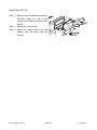
5.2.
Installing the Batteries for Type L
Step 1 Turn off the display.
Remove the AC adapter.
Step 2 Press and slide the ext. cover to open it.
Press the hook of the int. cover to the left
side and lift it.
Step 3 Insert six new batteries with proper polarity
(+,-). Battery is of type D, Mono, R20P ,
R20PU or LR20.
Step 4 Close the covers in reverse order of step 2.
Caution
Replace used batteries with six new ones, when
is displayed.
Do not mix used and new batteries. It may cause damage to the batteries or
the scale, if used.
Check the battery direction. If the batteries are installed in the wrong
direction, it may cause battery leakage. If the direction of a single battery is
wrong, the scale may work only temporarily.
The battery life depends on the ambient temperature.
Remove the batteries from the display unit, when the scale is not to be used
for a long time. They may leak and cause damage.
Damage which is due to battery leakage is not covered under warranty.
HV-G/HW-G Series
Page 13
5. Installing the Scale
5.3.
Removing the Pole
Caution
Remove the AC plug from the receptacle before removing the pole (type V).
Remove the AC adapter and batteries before removing the pole (type L).
When removing the load cell cable, do not pull on the load cell cable
connector forcibly and do not pull on the wires of the cable.
Do not bend the cable forcibly. Use care so that the load cell cable does not
touch the pan inside the base unit.
Avoid dust, static electricity and high humidity (or condensation) because the
inside of the display unit is sensitive.
The pole removing procedure depends on the scale model. Refer to the table below.
Models
Refer to
HV-15KGL/HV-15KGV/HV-60KGL/HV-60KGV/HV-200KGL/HV-200KGV/HW-10KGL
HW-10KGV/HW-60KGL/HW-60KGV/HW-100KGL/HW-100KGV/HW-200KGL/HW-200KGV
HW-300KGL4/HW-300KGV4/HW-600KGL4/HW-600KGV4/HW-600KGL3/HW-600KGV3
HW-1200KGL3/HW-1200KGV3
Procedure A
Procedure B
5.3.1. Procedure A
Step 1 Turn the scale off.
Cable clamp
Rear cover
Remove the AC plug from the receptacle (type V).
Remove the AC adapter and batteries (type L).
Step 2 Open the rear cover of the display unit.
Ferrite core
Disconnect the load cell cable connector gently
Wind up 2 times
(perpendicularly and do not pull toward you).
Connector
Step 3 Remove the two 4 mm screws, which are used
to attach the display unit to the pole.
Load cell cable
Step 4 Remove the ferrite core and the cable clamp
4 mm screw
from the load cell cable.
Bracket (Middle and large sized models)
Step 5
(HV-60KGL/HV-60KGV/HW-60KGL/HW-60KGV/HV200KGL/HV-200KGV/ /HW-100KGL/HW-100KGV
HW-200KGL/HW-200KGV only)
Remove the 3 mm screws from the bottom
cover of the bracket.
Step 6 Carefully remove the load cell cable from the
pole and the bracket while using care not to pull
on the connector forcibly.
Step 7 Arrange the cable so that it does not touch the
pan in the base unit. The untied cable is
approximately 2 m. The optional extension load
cell cable (OP-02) is 5 m long.
Step 8 Remove the bracket from the base unit. An
Allen wrench is required.
HV-15KGL/HV-15KGV
HV-60KGL/HV-60KGV
HW-10KGL/HW-10KGV
HW-60KGL/HW-60KGV
5 mm Allen wrench
5. Installing the Scale
Pole
Bottom cover
3 mm screws
Allen wrench
Allen screw
HV-200KGL/HV-200KGV
HW-100KGL/HW-100KGV
HW-200KGL/HW-200KGV
6 mm Allen wrench
Page 14
Bracket
HV-G/HW-G Series
Step 9 Wind the cable through the ferrite core two
times. Affix the cable to the rear cover using the
cable clamp.
Step 10 Connect the cable to the connector. Close the
rear cover.
Step 11 Check the weighing accuracy.
5.3.2. Procedure B
Step 1 Turn the scale off.
Remove the AC plug from the receptacle (type V).
Remove the AC adapter and batteries (type L).
Step 2 Open the rear cover of the display unit.
Disconnect the load cell cable connector gently
(perpendicularly and do not pull toward you).
Step 3 Remove the two 4 mm screws, which are used
to attach the display unit to the pole.
Step 4 Remove the ferrite core and the cable clamp
from the load cell cable.
Step 5 Carefully remove the load cell cable from the
pole using care not to pull on the connector
forcibly.
Step 6 Arrange the cable so that it does not touch the
pan in the base unit. The untied cable is
approximately 4.5 m. The optional extension
load cell cable (OP-02) is 5 m long.
Step 7 Remove the Allen screws, which are used to
attach the pole to the base unit, and remove
the pole.
Step 8 Wind the cable through the ferrite core two
times. Affix the cable to the rear cover using the
cable clamp.
Step 9 Connect the cable to the connector. Close the
rear cover.
Step 10 Check the weighing accuracy.
HV-G/HW-G Series
Page 15
5. Installing the Scale
5.4.
Grounding the scale
When using where there may be static electricity, ground the scale.
The grounding procedure depends on the scale model. Refer to the table below.
These procedures are only for grounding part of the scale.
Models
Refer to
HV-15KGL/HV-15KGV/ HW-10KGL/HW-10KGV
HV-60KGL/HV-60KGV/HV-200KGL/HV-200KGV/HW-60KGL/HW-60KGV
HW-100KGL/HW-100KGV/HW-200KGL/HW-200KGV
HW-300KGL4/HW-300KGV4/ HW-600KGL4/HW-600KGV4
HW-600KGL3/HW-600KGV3/ HW-1200KGL3/HW-1200KGV3
Procedure A
Procedure B
Procedure C
Procedure D
Procedure A
(HV-15KGL/HV-15KGV/ HW-10KGL/HW-10KGV)
Base unit
bottom side
Secure the grounding cable using a M4 screw in the
screw hole between the two hexagon bolts on the
base unit bottom side. (Part of “ ”)
Levering feet
Under cover
Base unit
bottom side
Procedure B
HV-60KGL/HV-60KGV/HV-200KGL/HV-200KGV/HW-60KGL/
HW-60KGV/HW-100KGL/HW-100KGV/HW-200KGL/HW-200KGV
Secure the grounding cable using the screw that
secures the under cover. (Part of “ ”)
Procedure C
(HW-300KGL4/HW-300KGV4/ HW-600KGL4/HW-600KGV4)
Pull the grounding
cable through to the
under side of the base.
Remove the pan. Secure the grounding cable using
the screw that secures the band of the load cell cable
bundle. (Part of “ ”)
Pull the grounding cable through to the lower section
through the channel. Be careful that the pan does not
touch the grounding cable.
Load cell
cable
Procedure D
(HW-600KGL3/HW-600KGV3/HW-1200KGL3/HW-1200KGV3)
Remove the pan. Secure the grounding cable using
the screw that secures the summing box. (Part of “ ”)
Remove the cover located on the base’s side. Pull the
grounding cable out through this hole. Be careful that
the pan does not touch the grounding cable.
5. Grounding the scale
Page 16
Summing box
Cover
HV-G/HW-G Series
6. Description of Each Part
HV-G/HW-G Series
Page 17
6. Description of Each Part
6. Description of Each Part
Page 18
HV-G/HW-G Series
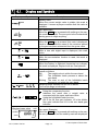
6.1.
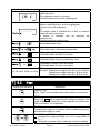
Display and Symbols
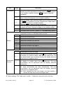
Display and Symbols
Description
Stability mark
When the current weight value is stable, this mark is
displayed. It means a proper condition that this value is
readable.
Zero point mark
When the ZERO key is pressed with nothing on the pan,
this mark is displayed. The zero point is the fundamental
starting point to weigh anything.
Net mark
When the TARE key is pressed, this mark is displayed.
Used to indicate that the mass of the container placed
on the pan has been subtracted from the gross value.
Preset tare mark
While a tare with digital input is displayed, this mark
blinks.
Accumulation mark
While the accumulation function is used, this mark is
displayed.
Low battery mark for type L
When the battery is depleted (becoming low voltage),
this mark is displayed. Replace with six new batteries.
Ready mark for the full/dribble batch function. This mark
means as follows:
ON
The weight value is within the zero band.
OFF
The full/dribble batch process is above the
zero band.
Blinking The start or end of the full/dribble batch
process is not within the zero band.
Weighing range indicator for the HV-G series
The current range is indicated.
Comparator indicator
Using the comparator function:
Indicates the result after a weight value is
compared with the upper and lower limits.
Using the full/dribble batch function:
OK is the full flow gate indicator, HI is the dribble
flow gate indicator and LO is the zero band gate
indicator.
Weighed mass value
STABLE
ZERO
HV-G/HW-G Series
A
A
A
A
A
A
A
A
A
A
A
A
A
A
A
A
A
A
A
A
A
A
A
A
A
A
A
A
A
A
A
A
A
A
unit
A
Zero point (Example)
When the ZERO key is pressed with nothing on the pan, A
the zero point mark and the stability mark are displayed. A
A
Page 19
6. Description of Each Part
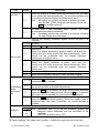
Display and Symbols
Description
Counting mode (Example)
This mode uses the stored unit mass and counts the
number of articles on the pan. The unit is
.
Storing the unit mass for the counting mode (Example)
The unit mass is stored, using 20 pieces of samples.
The zero value means that no articles are on the pan.
Storing the unit mass for the counting mode (Example)
The unit mass is stored, using 10 pieces of samples.
Sign "-" means that something is placed on the pan.
Percentage mode (Example)
This mode uses the stored 100% mass and converts the
weight value to a percentage. The unit is % .
Function table (Example)
This function table sets parameters of items.
ENTER key
Selecting an item.
∧ and <keys
Selecting a parameter of the item.
ENTER key
Storing new parameters.
Preset tare. Entering tare with digital input (Example)
< key
Selecting the figure to be changed.
∧ key
Changing the number of the figure.
ENTER key
Storing the new tare.
Hold display (Example)
The hold display is set using f12 of the function table.
When the weight value is "nearly-zero" (within the zero
band) or changes more than 25% +30 digits, the hold is
canceled.
Weighing error
Check the base unit and the weighing pan.
Overload display
Remove anything that is on the pan.
Calibration error
The calibration mass is too light.
Check the base unit and the weighing pan.
The "digit" is a unit of display, and is equivalent to the minimum measurable mass.
The " nearly-zero " or zero band is within ±5 digits from zero point in the unit of kg.
6. Description of Each Part
Page 20
HV-G/HW-G Series
A
A
A
A
A
A
A
A
A
A
A
A
A
A
A
A
A
A
A
A
A
A
A
A
A
A
A
A
A
A
A
A
A
A
A
A
A
A
A
A
A
A
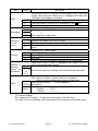
Display and Symbols
A
A
Calibration error
A
The calibration mass is too heavy.
A
Check the base unit and the weighing pan.
A
Does not display zero when the scale is turned on.
A
Remove anything that is on the weighing pan.
A
Perform zero point calibration.
A
Or
The weight value is unstable due to drift or vibration A
Description
when the scale is turned on.
A breeze or vibration may
measurement.
Check around the weighing pan.
be
affecting
the
A
A
A
Total mass value of the accumulated data
A
A
Comparator function: upper limit value
Full/dribble batch function: final value
A
A
Full/dribble batch function: preliminary value
A
A
Comparator function: lower limit value
Full/dribble batch function: zero band
A
The weighing range and measurable minimum mass.
A
Example: Displays the weight value by 5 g up to 15 kg. A
e.g. CAP. MAX. 3/6/15kg d=1/2/5g
Displays the weight value by 2 g up to 6 kg.
Accumulated data count
Displays the weight value by 1 g up to 3 kg.
6.2.
Keys
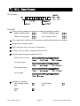
Display and Symbols
Description
ON/OFF key
Note Type V is in standby status when power is connected.
ZERO key
When the ZERO key is pressed with nothing on the pan, the
scale displays the mass value of zero and the zero point mark.
Net is canceled, if it is displayed.
TARE key
Canceling the mass of a container which is placed on the pan
and does not weigh its mass.
SAMPLE key, RANGE key, key
Changes the weighing range for HV-G series.(Refer to
f2 )
Storing the unit mass: used to select the number of samples.
HV-G/HW-G Series
Page 21
6. Description of Each Part
A
A
A
A
A
A
A
A
A
A
A
A
A
A
Display and Symbols
Function table: used to select a parameter.
Description
SET key, key
Normal weighing mode: used to turn the comparator on or
off. (Refer to f6 )
Counting mode: used to enter the mode to store the unit
mass.
Percentage mode: used to enter the mode to store the
100% mass.
Full/dribble batch function: used as a start key.
Preset tare and calibration mass selection: used to select
a figure.
A
A
A
A
A
A
A
A
A
A
A
A
A
A
A
F key
Full/dribble batch function: used to finish the process. A
(Refer to f10 )
A
Hold key. (Refer to f12 )
A
Comparator function: used to select the polarity (+,-).
A
A
PRINT key
A
Used to print or output data. (Refer to f5, f9 )
A
A
A
A
Used to enter the function table.
A
A
A
A
A
Used to enter the mode to set a preset tare.
A
A
A
A
A
Used to feed the paper to the optional printer for type V.
A
A
A
MODE key, ENTER key
Used to change the current unit.
Setting mode: used to store a parameter and proceed to the
next step.
6. Description of Each Part
Page 22
HV-G/HW-G Series
7. Basic Operation
7.1.
Turning the Scale on/off and Weighing
7.1.1. Type V or Type L with AC Adapter
Step 1 Ground the scale.
Step 2 Confirm that nothing is placed on the pan.
Step 3 Confirm that local voltage and receptacle type are correct.
Step 4 The scale turns on/off using the ON/OFF key alternately.
Step 5 Check the accuracy of weighing. Allow 30-minute warm up before calibration.
Step 6 With nothing on the pan, press the ZERO key to display zero.
Step 7 Place an article to be weighed on the pan gently.
Step 8 Wait for the stability mark to be displayed. Read the weight value.
Step 9 Remove the article from the pan.
Step 10 Turn the scale off using the ON/OFF key.
Memo
With the power cord connected, type V is in standby status after the scale is turned off
using the ON/OFF key. To shut down the power completely, disconnect the power
cord.
With the AC adapter connected, the power is off at the scale, but not from the AC
adapter, after the scale is turned off using the ON/OFF key. To shut down the power
completely, disconnect the AC adapter.
HV-G/HW-G Series
Page 23
7. Basic Operation
7.1.2. Type L with Batteries
Step 1 Install six new batteries. Refer to "5.2. Installing the Batteries for Type L".
Step 2 Confirm that nothing is placed on the pan.
Step 3 The scale turns on/off using the ON/OFF key alternately.
Step 4 Check the accuracy of weighing. Allow 30-minute warm up before calibration.
Step 5 With nothing on the pan, press the ZERO key to display zero.
Step 6 Place an article to be weighed on the pan gently.
Step 7 Wait for the stability mark to be displayed. Read the weight value.
Step 8 Remove the article from the pan.
Step 9 Turn the scale off using the ON/OFF key.
Caution
Replace used batteries with six new ones when
is displayed.
Battery life depends on the ambient temperature.
Remove the batteries from the display unit when the scale is not to be used
for a long time. The batteries may leak and cause damage.
7. Basic Operation
Page 24
HV-G/HW-G Series
7.2.
Tare (And Net Display)
The "tare" is used to cancel the mass of a container, which is placed on the pan to
contain the article to be weighed.
Caution
The tare reduces the weighing range.
The current tare value is reset by pressing the ZERO key or turning the scale
off. (Reset value is zero.)
The storable preset tare value must be within the minimum weighing range for
the HV-G series.
7.2.1. Tare Input by Weighing
Step 1 Place the container on the pan.
Step 2 Wait for the stability mark to be displayed. Press the TARE key. The display
becomes zero and the net mark is displayed.
Step 3 Place an article to be weighed into the container. Wait for the stability mark to be
displayed and read its net display.
Step 4 Remove the article and the container from the pan.
7.2.2. Digital Input (Preset Tare)
Step 1 Press and hold the SET key and press the TARE key.
Then the blank or stored tare value is displayed. The blank display means that the
tare value is zero (reset value). And or
blinks.
Step 2 Set the preset tare value using the following keys.
< key
Selecting the figure to be changed.
∧ key
Changing the number of the figure.
Step 3 Press the ENTER key to store the new preset tare value.
Then the scale displays the net value (the gross weight value minus the tare value).
Step 4 Place an article to be weighed into the container. Wait for the stability mark to be
displayed and read its net display.
Step 5 Remove the article and the container from the pan.
HV-G/HW-G Series
Page 25
7. Basic Operation
7.3.
Weighing Range for the HV-G Series
This is the function to select a weighing range for the HV-G series.
The mass value is displayed within a selected range.
Select automatic range (f2 0) or manual range (f2 1) in the function table.
Operation and Performance
Function table
f2 0
f2 1
A
A
Automatic range
The weighing range changes automatically, if the weight value A
proceeds from narrow range to wide range when articles are A
placed on the pan.
A
When there is nothing on the pan and the zero point mark is A
displayed, the weighing range changes to the minimum range
A
automatically.
When the zero point mark is not displayed due to net display A
or zero error, press the ZERO key, with nothing on the pan, to A
change to the minimum range.
A
Description
Manual range
Press the RANGE key to expand the range.
Press the RANGE key to change to the minimum range, when
there is nothing on the pan and the zero point mark is
displayed.
When the zero point mark is not displayed due to net display
or zero error, press the ZERO key and the RANGE key, with
nothing on the pan, to change to the minimum range.
Weighing Range
Models
HV-15KGV, HV-15KGL
HV-60KGV, HV-60KGL
HV-200KGV, HV-200KGL
7. Basic Operation
Weighing range
3 kg,
6 kg ,
15 kg,
30 kg,
60 kg,
150 kg,
Page 26
15 kg
60 kg
220 kg
HV-G/HW-G Series
A
A
A
A
A
A
A
A
A
A
A
A
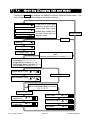
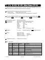
7.4.
Mode Key (Changing Unit and Mode)
Pressing the MODE key changes the display as follows. Refer to function table f3 for
units. Usable units are according to the factory settings.
If the law in your area
permits, you may use all
of the units. Also, some
dealers may initially turn
off units which are not
regularly used.
Pound
Ounce
Pound-Ounce
Non metric units
Metric unit
Metric kg
Counting Mode
Percentage Mode
Inactive Comparator (f6)
and
Inactive Accumulation Function (f8 0)
Either function is active.
Comparator (f6 0 ~ f6 7)
Simple Batch Function (f6 8)
Full/Dribble Batch Function (f6 9)
Accumulation Function (f8 1)
Accumulation Count
M+
or
No Accumulation Data
Accumulation Value
M+
or
Active Simple Batch Function or
Active Full/Dribble Batch Function
(f6 8, f6 9)
Active Comparator
(f6 0 ~ f6 7)
Comparator
Upper limit
Comparator
Lower limit
Final value
or
HI or
LO or
Preliminary value OK or
Zero band
HV-G/HW-G Series
HI
Page 27
LO or
7. Basic Operation
Description
The status of "Inactive comparator (f6)" is that comparator function (f6 0, f6 2, f6 4,
f6 6) is selected and this comparator is not used. The comparator can be selected to
be ON or OFF using the SET key alternately.
The following parameters are stored in the same memory. Therefore these functions
can not be used at the same time. If you use each function, select the function in the
function table, set the parameters (HI,OK and LO) and weigh.
Indicator and Output
HI
Upper/Lower Comparator Function (f6 0 to 7) Upper limit
Simple Batch Function (f6 8)
Full/ Dribble Batch Function (f6 9)
7. Basic Operation
Page 28
Final
value
Final
value
OK
LO
Lower limit
Preliminary
Zero band
value
Preliminary
Zero band
value
HV-G/HW-G Series
8. Counting Mode
The counting mode is the function to convert the total mass value (total weight) of
articles to a count, when each article has the same mass value.
To use this function, store a unit mass in advance.
Even if the AC adapter or the batteries is removed, the unit mass is maintained in
non-volatile memory.
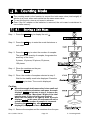
8.1.
Storing a Unit Mass
Step 1 Press the MODE key to display the unit
.
Step 2 Press the SET key to enter the mode that stores a
unit mass.
Step 3 Press the ∧ key to select the number of samples.
The greater the quantity of samples, the greater the
accuracy of the count.
5 pieces, 10 pieces, 20 pieces, 50 pieces,
100 pieces
Step 4 Place the container on the pan.
Press the TARE key.
Step 5 Place the number of samples selected at step 3.
Wait for the stability mark to be displayed. Press the
ENTER key to store. The count is displayed.
Caution
When the sample total mass value is too small and
it is not possible to calculate a unit mass, the scale
displays lo ut and returns to step 3. Increase the
number of samples. More than 5 digits of the total
sample mass, in the unit of kg, are required.
When the unit mass is too light to store, the scale
displays lo ut . In this case, the unit mass will not be
stored even if the number of samples is increased.
Pressing the ENTER key, after lo ut is
displayed, displays the next unit.
Step 6 Remove the samples and the container from the pan.
HV-G/HW-G Series
Page 29
8. Counting Mode
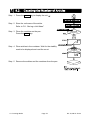
8.2.
Counting the Number of Articles
Step 1 Press the MODE key to display the unit
.
Step 2 Store the unit mass of the article.
Refer to "8.1. Storing a Unit Mass"
Step 3 Place the container on the pan.
Press the TARE key.
Step 4 Place articles in the container. Wait for the stability
mark to be displayed and read the count.
Step 5 Remove the articles and the container from the pan.
8. Counting Mode
Page 30
HV-G/HW-G Series
9. Percentage Mode
The percentage mode is the function to display a mass value in the unit of "%".
To use this function , store a 100% mass value in advance.
The 100% mass value is stored in the scale even if the power is removed.
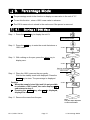
9.1.
Storing a 100% Mass
Step 1 Press the MODE key to display the unit %.
Percentage mode
Step 2 Press the SET key to enter the mode that stores a
100% mass.
%
STABLE
Pan
Step 3 With nothing on the pan, press the ZERO key to
display zero.
STABLE
Zeroing value
100% mass
Step 4 Place the 100% mass on the pan gently.
Wait for the stability mark to be displayed. Press the
ENTER key to store. The percentage is displayed.
Caution
When the sample is too light and it is not possible
to calculate a 100% mass, the scale displays lo .
and returns to step 3.
Pressing the ENTER key, after lo is displayed,
displays the next unit.
STABLE
Step 5 Remove the mass from the pan.
Note
The pan shape depends
on the scale model.
HV-G/HW-G Series
Page 31
9. Percentage Mode
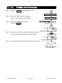
9.2.
Reading the Percentage
Step 1 Press the MODE key to display the unit %.
Percentage mode %
Step 2 Store the 100% mass of the article.
Refer to "9.1. Storing a 100% Mass "
Storing a 100% mass
A container(bowl)
Step 3 Place the container on the pan.
Press the TARE key.
Pan
STABLE
Zeroing value
Step 4 Place articles in the container. Wait for the stability
mark to be displayed and read the percentage.
STABLE
Step 5 Remove the articles and the container from the pan.
Percentage
Note
The pan shape depends
on the scale model.
9. Percentage Mode
Page 32
HV-G/HW-G Series
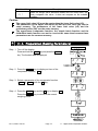
10. Accumulation Function
This function counts the number of times articles are weighed, calculates the total mass
value and can display the number (accumulation count) and accumulated mass value.
The accumulation function is displayed with up to 6 digits. The balance can not display 7 or
more digits, therefore the leading digits are not displayed.
Example: With 60K type, when importing the data of 17 accumulations of up to 60kg (60.000
X 17=1020.000), the balance displays this as “020.000”.
To use this function, set the parameters of the "Accumulation function ( f8 )" in the
function table in advance.
To use the built-in printer, set the parameters of the "Print mode ( f9 5
function table in advance.
)" in the
The accumulation count and accumulated mass value are stored in the scale even if
the power is removed.
Operation and Keys
The display of the accumulation count has a blinking
or
without a unit.
The display of the accumulated mass value has a unit and a blinking
or
.
Press the MODE key to display the accumulation count and accumulated mass value.
Press the ZERO key in the accumulation function (with a blinking
or
the current function (The count and accumulated mass value become zero.)
) to reset
When the optional built-in printer is installed and the PRINT key is pressed, the
accumulation data, date and data number are printed. Date is set at function table f17 .
Caution
The accumulation function is available only when weighing is performed in the
same unit.
Parameter List and Word Definition
The "nearly-zero" is within ±5 digits from the zero point in the unit of kg.
The "digit" is a unit of display, and is equivalent to the minimum measurable mass.
The "zero point" is the fundamental starting point to weigh anything.
Function table
Description
Accumulation function not used.
f8 0
f8 1
The scale accumulates the data, if the F key is pressed, when the
display is a positive stable value and not nearly-zero. The next
accumulation can be performed after the display becomes
nearly-zero or a negative value.
f8 2
The scale accumulates the data, if the F key is pressed, when the
display is a stable value and not nearly-zero. The next accumulation
can be performed after the display becomes nearly-zero.
HV-G/HW-G Series
Page 33
10. Accumulation Function
A
A
A
A
A
A
A
A
A
Function table
f8 3
f8 4
f8 5
Description
When the display is a positive stable value and not nearly-zero, the
scale accumulates the data automatically. The next accumulation
can be performed after the display becomes nearly-zero or a
negative value.
When the display is a stable value and not nearly-zero, the scale
accumulates the data automatically. The next accumulation can be
performed after the display becomes nearly-zero.
Use
Recording the number and mass of articles removed from
the pan. (Place the articles on the pan. Press the TARE key
at each removal.)
At each end of the full/dribble batch function, the scale accumulates
the data automatically.
Use
Packaging articles like a powder, it is used for recording the
number of bags and the total mass.
10.1. Preparation (Setting Parameters)
Step 1 Turn off the display.
Press and hold the ZERO key and press the
ON/OFF key. The function table is displayed.
Step 2 Press the ENTER key to display an item of the
accumulation function ( f8 ).
Step 3 Select a parameter of the accumulation function
( f8 1 to f8 4 ) with the ∧ key.
Step 4 Press the ENTER key and the F key to display
end . Press the ENTER key to return to the
normal weighing mode.
10. Accumulation Function
Page 34
HV-G/HW-G Series
A
A
A
A
A
A
A
A
A
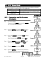
10.2. Operation and Performance (Examples)
Example 1
In this example, the scale accumulates the value each time an article is weighed. The
function parameter is set to f8 3 .
Step 1 Press the MODE key to display
or
.
Step 2 Press the ZERO key to reset the accumulation data.
Step 3 Return to the kg mode using the MODE key.
Step 4 Place an article on the pan. Wait for the stability mark to be displayed and the value
to be blinking. Remove the article and press the ZERO key.
Step 5 Weigh additional articles using step 4.
Step 6 Press the MODE key to display the accumulation count and accumulated mass
value with
or
.
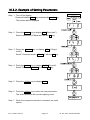
Example 2
In this example, the scale accumulates the articles that are removed from the pan.
The function parameter is set to f8 4 .
Step 1 Enter the kg mode using the MODE key.
Place all articles on the pan and press the TARE key.
Step 2 Press the MODE key to display
or
.
Step 3 Press the ZERO key to reset the accumulation data.
Return to the kg mode using the MODE key.
Step 4 Remove an article from the pan. Wait for the stability mark to be displayed and the
value to be blinking. Press the TARE key.
Step 5 Weigh additional articles using step 4.
Step 6 Press the MODE key to display the accumulation count and accumulated mass
value with
HV-G/HW-G Series
or
.
Page 35
10. Accumulation Function
11. Upper/Lower Comparator Function
This function compares a weight value with the upper limit (HI) and the lower limit
(LO) and displays the results.
To use this function, set the "Comparator function ( f6 0 to f6 7 )" parameters in the
function table, upper limit value (HI) and lower limit value (LO).
Install option OP-03 or OP-04 to use relay output of the comparator.
Install option OP-03 to use buzzer output of the comparator.
The settings are stored in the scale even if the power is removed. (Refer to Caution
on the next page.)
Comparator Indicators
Comparison results are displayed by indicators
or
Comparison Condition
Weight value < Lower limit value ..................................LO is displayed and output.
Lower limit value ≦ Weight value ≦ Upper limit value......OK is displayed and output.
Upper limit value< Weight value ........................................HI is displayed and output.
Parameter List and Word Definition
The decimal point is not displayed in the upper or lower limit value settings.
The " nearly-zero " is within ±5 digits from the zero point in the unit of kg.
Function table
f6 0
f6 1
f6 2
f6 3
f6 4
f6 5
f6 6
Description
Press the SET key to compare the current weight value always.
Press the SET key again to stop the comparison.
The scale always compares the weight value.
Press the SET key to always compare the weight value when not
nearly-zero.
Press the SET key again to stop the comparison.
The scale always compares the weight value when not nearly-zero.
When the weight value becomes stable after the SET key is
pressed, the scale compares the weight value. It does not compare on
an unstable condition. Press the SET key again to stop the
comparison.
When the weight value is stable, the scale compares the weight
value. It does not compare on an unstable condition.
When the weight value becomes stable and not nearly-zero after
pressing the SET key, the scale compares the weight value. It does
not compare on an unstable condition.
Press the SET key again to stop the comparison.
11. Upper/Lower Comparator Function
Page 36
HV-G/HW-G Series
A
A
A
A
A
A
A
A
A
A
A
A
A
A
A
A
Function table
f6 7
Description
A
When the weight value becomes stable and not nearly-zero, the A
scale compares the value. It does not compare on an unstable A
condition.
Caution
The upper limit value (HI) must be greater than the lower limit value (LO).
The parameters of the upper limit value (HI) and the final value (HI) use the
same memory. The parameters of the lower limit value (LO) and the
preliminary value (OK) use the same memory.
The upper/lower comparator function, the simple batch function and the
full/dribble batch function can not be used at the same time because these
parameters use the common memory.
11.1. Preparation (Setting Parameters)
Step 1 Turn off the display.
Press and hold the ZERO key and press the ON/OFF
key. The function table is displayed.
Step 2 Press the ENTER key to display an item of the
comparator function ( f6 ).
Step 3 Select a parameter of the comparator function
( f6 0 to f6 7 ) with the ∧ key.
Step 4 Press the ENTER key and the F key to display end .
Press the ENTER key to return to the normal
weighing mode.
HV-G/HW-G Series
Page 37
11. Upper/Lower Comparator Function
Step 5 If either of f6 0 , f6 2 , f6 4 , f6 6 has been
selected, press the SET key to use the
comparator.
Step 6 Press the MODE key to display the blinking HI.
Step 7 Set the upper limit value using the following keys.
< key
Selecting the figure to be changed.
∧ key
Changing the number of the figure.
F key
Selecting the polarity (+,-).
Step 8 Press the ENTER key to store the new parameter and
display the blinking LO.
Step 9 Set the lower limit value using the following keys.
< key
Selecting the figure to be changed.
∧ key
Changing the number of the figure.
F key
Selecting the polarity (+,-).
Step 10 Press the ENTER key to store the new parameter and
return to the normal weighing mode.
If the lower limit value is greater than the upper limit
value, the scale returns to step 7.
11. Upper/Lower Comparator Function
Page 38
HV-G/HW-G Series
11.2. Operation and Performance (Examples)
Example 1
This example is set as follows:
Function table
f6 1
Upper limit value (HI)
Lower limit value (LO)
(The scale always compares the weight value
even when the value is nearly-zero.)
7.000 kg
6.500 kg
Case
The comparison starts when the scale is turned on.
When the current value is less than 6.500kg, LO is displayed.
When the current value is between 6.500kg and 7.000kg, OK is displayed.
When the current value is greater than 7.000kg, HI is displayed.
Example 2
This example is set as follows:
Function table
f6 4
Upper limit value (HI)
Lower limit value (LO)
(When the SET key is pressed and the stability
mark is displayed, the scale compares the
current weight value with the upper limit value
and the lower limit value immediately.)
2.000 kg
-1.000 kg
Case
The comparison starts when the SET key is pressed and the stability mark is
displayed.
When the current value is less than -1.000kg, LO is displayed.
When the current value is between -1.000kg and 2.000kg, OK is displayed.
When the current value is greater than 2.000kg, HI is displayed.
HV-G/HW-G Series
Page 39
11. Upper/Lower Comparator Function
12. Full/Dribble Batch Function
This function changes the scale to a filling machine which sub-divides a bulk product
( like grain) into loads of predetermined and virtually constant mass.
To use this function, set the parameter of the "Comparator function ( f6 9 )",
" Full/dribble batch sub-function ( f10 0 to f10 3 )" in the function table, final value
(HI), preliminary value (OK) and zero band (LO).
Install option OP-03 or OP-04 to use the relay output of the full/dribble batch function.
In case of building up a filling machine with a scale and hopper, the performance is as
follows:
The settings are stored in the scale even if the power is removed. (Refer to Caution
on the next page.)
A
Zero band
Preliminary value
Final value
indicator/
indicator/
indicator/
A
LO relay output OK relay output HI relay output A
Gross < Zero band (Zero detection Level)
Net < Final - Preliminary
Final - Preliminary ≦ Net < Final
Final ≦ Net
12. Full/Dribble Batch Function
ON / Make
OFF / Break
OFF / Break
OFF / Break
Page 40
OFF / Break
ON / Make
OFF / Break
OFF / Break
OFF / Break
ON / Make
ON / Make
OFF / Break
HV-G/HW-G Series
A
A
A
A
Caution
The comparison of the full/dribble batch function can not be restored. (One
way sequence). If the weight value becomes less than the final value after the
value reached a predetermined target value, neither HI nor LO is on.
The parameters of the upper limit value (HI) and the final value (HI) use the
same memory. The parameters of the lower limit value (LO) and the
preliminary value (OK) use the same memory.
The upper/lower comparator function, the simple batch function and the
full/dribble batch function can not be used at the same time because these
parameters use the common memory.
Set the zero band greater than the tare value.
Operation
The batch process starts when the SET key is pressed.
When a parameter from f10 0 or f10 2 of the full/dribble batch sub-function is
selected, the F key functions as the finish key.
Parameter List and Word Definition
The "gross" is a total weight value (the tare value is not subtracted).
The "net" is a measurement value with the tare value subtracted from the gross.
The "zero band" means the zero detection level.
The "zero point" is the fundamental starting point to weigh anything.
Comparator
Function table
Description
Full/dribble batch function.
f6 9
A
A
Full/dribble batch sub-function
Function table
Description
A
When the F key is pressed after final value is reached, the current A
f10 0
process is finished.
A
f10 1
f10 2
f10 3
When the stability mark is displayed after final value is reached, A
the current process is finished.
A
When the SET key is pressed, the scale automatically tares and
starts the full/dribble batch process. When the F key is pressed
after final value is reached, the current process is finished.
When the SET key is pressed, the scale automatically tares and
starts the full/dribble batch process. When the stability mark is
displayed after final value is reached, the current process is
finished.
Hold
Function table
Description
The hold function is not used.
f12 0
HV-G/HW-G Series
Page 41
12. Full/Dribble Batch Function
A
A
A
A
A
A
A
A
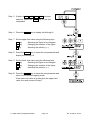
12.1. Preparation (Setting Parameters)
Step 1 Turn off the display.
Press and hold the ZERO key and press the ON/OFF key.
The function table is displayed.
Step 2 Press the ENTER key to display an item of the
comparator function ( f6 ).
Step 3 Select a parameter of the full/dribble batch function
( f6 9 ) with the ∧ key.
Step 4 Press the ENTER key to store the new parameter and
display an item of the full/dribble batch sub-function
( f10 ) .
Step 5 Select a parameter of the full/dribble batch
sub-function ( f10 0 to f10 3 ) with the ∧ key.
Step 6 Press the ENTER key and the F key to display end .
Step 7 Press the ENTER key to return to the normal weighing
mode.
12. Full/Dribble Batch Function
Page 42
HV-G/HW-G Series
Step 8 Press the MODE key to display the blinking HI (of the
final value).
Step 9 Set the final value using the following keys.
< key
Selecting the figure to be changed.
∧ key
Changing the number of the figure.
Step 10 Press the ENTER key to store the new parameter and
display the blinking OK (of preliminary value).
Step 11 Set the preliminary value using the following keys.
< key
Selecting the figure to be changed.
∧ key
Changing the number of the figure.
Step 12 Press the ENTER key to store the new parameter and
display the blinking LO (of zero band).
Step 13 Set a zero band which is greater than the tare value,
using the following keys.
< key
Selecting the figure to be changed.
∧ key
Changing the number of the figure.
Step 14 Press the ENTER key to store the new parameter and
return to the normal weighing mode.
HV-G/HW-G Series
Page 43
12. Full/Dribble Batch Function
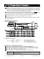
13. Simple Batch Function
This function compares a weight value with the final value, preliminary value and zero
band for the full/dribble batch function. The result is indicated by zero band (LO
indicator), full flow (HI indicator) and dribble flow (OK indicator). Even if the weight
value is increasing or decreasing, this function can compare it.
To use this function, set the parameters of the "Simple batch function ( f6 8 )" in the
function table, final value (HI), preliminary value (OK) and zero band (LO).
Install option OP-03 or OP-04 to use the relay output of the comparison.
Install option OP-03 to use the buzzer output of the comparator.
The settings are stored in the scale even if the power is removed. (Refer to Caution
on the next page.)
Comparison Condition
Gross < Zero band ..............LO is displayed and output.
Final - Preliminary ≦ Net .........................OK is displayed and output.
Final ≦ Net .........................OK, HI are displayed and output.
Parameter List and Word Definition
The "gross" is a total weight value (the tare value is not subtracted).
The "net" is a measurement value with the tare value subtracted from the gross.
The "tare" is an item placed on the pan and its mass is subtracted from the gross.
The "zero band" means the zero detection level.
The "zero point" is the fundamental starting point to weigh anything.
Function table
Simple batch function
f6 8
13. Simple Batch Function
Page 44
A
A
Description
HV-G/HW-G Series
Caution
The parameters of the upper limit value (HI) and a final value (HI) use the
same memory. The parameters of the lower limit value (LO) and the
preliminary value (OK) use the same memory.
The upper/lower comparator function, the simple batch function and the
full/dribble batch function can not be used at the same time because these
parameters use the common memory.
13.1. Preparation (Setting Parameters)
Step 1 Turn off the display.
Press and hold the ZERO key and press the ON/OFF key.
The function table is displayed.
Step 2 Press the ENTER key to display an item of the
comparator function ( f6 ).
Step 3 Select a parameter of the simple batch function
( f6 8 ) with the ∧ key.
Step 4 Press the ENTER key and the F key to display end .
Step 5 Press the ENTER key to return to the normal weighing
mode.
HV-G/HW-G Series
Page 45
13. Simple Batch Function
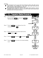
Step 6 Press the MODE key to display the blinking HI (of the
final value).
Step 7 Set the final value using the following keys.
< key
Selecting the figure to be changed.
∧ key
Changing the number of the figure.
Step 8 Press the ENTER key to store the new parameter and
display the blinking OK (of preliminary value).
Step 9 Set the preliminary value using the following keys.
< key
Selecting the figure to be changed.
∧ key
Changing the number of the figure.
Step 10 Press the ENTER key to store the new parameter and
display the blinking LO (of zero band).
Step 11 Set the zero band using the following keys.
< key
Selecting the figure to be changed.
∧ key
Changing the number of the figure.
Step 12 Press the ENTER key to store the new parameter and
return to the normal weighing mode.
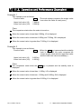
13.2. Operation and Performance (Examples)
Step 1 Select the parameter f6 8 of the function table.
Step 2 Set the parameters of the final value, preliminary value and zero band.
Step 3 The comparison result is always displayed.
Comparison Condition
Gross < Zero band ..........LO is displayed and output.
Final - Preliminary ≦ Net.....................OK is displayed and output.
Final ≦ Net .....................OK, HI are displayed and output.
13. Simple Batch Function
Page 46
HV-G/HW-G Series
14. Calibration (Adjusting the Scale)
The scale is an instrument which weighs the "weight" and displays its "mass".
Calibration is the adjustment function so that the scale can weigh correctly.
Three steps of calibration are available
Gravity Acceleration Correction ... The function to correct the scale’s local gravity
acceleration, so that the scale functions
correctly when the calibrated scale has been
moved to a distant place.
Refer to the "Gravity Acceleration Table" on
the next page.
Calibration of the Zero Point ......... The function to adjust the zero point, so that
the zero point mark is displayed when there is
nothing on the pan.
Comment The zero point is the fundamental starting point
to weigh anything and influences the
performance of scale.
Span Calibration.............................. The function to adjust the span with a
calibrated mass, so that the scale can
accurately weigh anything within the weighing
capacity.
Comment Span means the range of weighing capacity.
Use a calibration mass heavier than two thirds
of the weighing capacity.
Caution
Check the accuracy of weighing periodically. Calibrate the scale, if it has
been moved to another location or the environment has changed.
Gravity acceleration correction is not required, when the scale is calibrated
with the calibration mass at the place where the scale is used.
HV-G/HW-G Series
Page 47
14. Calibration (Adjusting Scale)
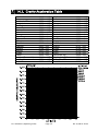
14.1. Gravity Acceleration Table
Amsterdam
Athens
Auckland, NZ
Bangkok
Birmingham
Brussels
Buenos Aires
Calcutta
Chicago
Copenhagen
Cyprus
Djakarta
Frankfurt
Glasgow
Havana
Helsinki
Kuwait
Lisbon
London (Greenwich)
Los Angeles
Madrid
14. Calibration (Adjusting Scale)
9.813
9.800
9.799
9.783
9.813
9.811
9.797
9.788
9.803
9.815
9.797
9.781
9.810
9.816
9.788
9.819
9.793
9.801
9.812
9.796
9.800
m/s2
m/s2
m/s2
m/s2
m/s2
m/s2
m/s2
m/s2
m/s2
m/s2
m/s2
m/s2
m/s2
m/s2
m/s2
m/s2
m/s2
m/s2
m/s2
m/s2
m/s2
Page 48
Manila
Melbourne
Mexico
Milan
New York
Oslo
Ottawa
Paris
Rio de Janeiro
Rome
San Francisco
Singapore
Stockholm
Sydney
Tainan
Taipei
Tokyo
Vancouver, BC
Washington, DC
Wellington, NZ
Zurich
9.784
9.800
9.779
9.806
9.802
9.819
9.806
9.809
9.788
9.803
9.800
9.781
9.818
9.797
9.788
9.790
9.798
9.809
9.801
9.803
9.807
m/s2
m/s2
m/s2
m/s2
m/s2
m/s2
m/s2
m/s2
m/s2
m/s2
m/s2
m/s2
m/s2
m/s2
m/s2
m/s2
m/s2
m/s2
m/s2
m/s2
m/s2
HV-G/HW-G Series
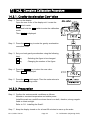
14.2. Complete Calibration Procedure
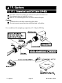
14.2.1. Gravity Acceleration Correction
Step 1 Turn on the display.
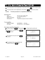
Open the rear cover of the display unit. Locate the
CAL switch inside.
Press and hold the CAL switch to enter the calibration
mode.
Then Cal 0 is displayed.
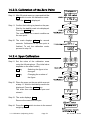
Step 2 Press the ZERO key to enter the gravity acceleration
correction mode.
Step 3 Set your local gravity acceleration using the following
keys.
< key
Selecting the figure to be changed.
∧ key
Changing the number of the figure.
Step 4 Press the ENTER key to store the new value.
Then Cal 0 is displayed.
Step 5 Press the CAL switch again. Then the scale returns to
the normal weighing mode.
14.2.2. Preparation
Step 6 Confirm the environmental conditions as follows:
Maintain a constant temperature and stable power.
Install the scale on a solid floor where there is no draft, vibration, strong magetic
fields or direct sunlight.
Refer to "4.1. Installing the Scale".
Step 7 Keep the display turned on for at least 30 minutes to warm up the scale.
HV-G/HW-G Series
Page 49
14. Calibration (Adjusting Scale)
14.2.3. Calibration of the Zero Point
Step 8 After 30-minute warm up, press and hold the
CAL switch to enter the calibration mode.
Then the Cal 0 is displayed.
Step 9 Confirm that nothing is placed on the pan.
Wait for the stability mark to be displayed.
Press the ENTER key.
The scale stores the current condition as
the zero point.
Step 10 The scale displays 5pn1 for several
seconds. Calibration of the zero point is
finished. To exit the calibration mode,
proceed to step 14.
14.2.4. Span Calibration
Step 11 Set the value of the calibration mass
using the following keys. (The initial value
depends on the scale model.)
< key
Selecting the figure to be
∧ key
changed.
Changing the number of
the figure.
Step 12 Place the mass on the pan which was set
at step 11. Wait for the stability mark to be
displayed. Press the ENTER key.
The scale then calculates the span and
stores it.
Step 13 The scale displays end .
Remove the mass from the pan.
Step 14 Press the CAL switch to return to the normal
weighing mode.
14. Calibration (Adjusting Scale)
Page 50
HV-G/HW-G Series
15. Function Table
The function table is used to store and refer items that determine the performance of
the scale. Each item has a parameter.
The parameters are stored in the scale even if the power is removed.
15.1. Parameter Setting Procedure
Step 1 Turn off the display.
Press and hold the ZERO key and press the ON/OFF key.
The function table is displayed.
Step 2 Set parameters for each item using the following keys.
∧ key
Selecting the parameter of an item.
< key
Selecting a figure.
F key
ENTER key
Proceeding to step 3 without storing the
parameter.
Storing a parameter for the current item
and proceeding to the next item.
Step 3 When the end of the table is reached,
displayed.
end is
Step 4 Press the ENTER key to store the new parameters and
return to the normal weighing mode.
HV-G/HW-G Series
Page 51
15. The Function Table
15.2. Parameter List
Item
Automatic
turning off
Weighing
range
Unit
Baud rate
f1 0 #
f1 1
f2 0 #
f2 1
f3
f3
f3
f3
0 #
1
2
3
f4 0 #
f4 1
f4 2
f5 0 #
f5 1
f5 2
Output
mode
f5 3
f5 4
f5 5
f6 0 #
Comparator
Description
A
The type L scale is turned off after 5 minutes of no operation,
when zero is displayed.
Not used
Used
Selects how to change the weighing range for HV-L and HV-G
series.
Automatic range
Manual range
Selects the first unit at the time when the scale turns on.
Kg
Lb
Oz
lb-oz
Selects the transmission rate of the serial interface (RS-232C/ 422/485).
2400 bps
4800 bps
9600 bps
Selects the mode for the serial interface (RS-232C/ 422/485).
Stream mode. (Refer to "16.2. Stream Mode")
Command mode. (Refer to "16.3. Command Mode")
A data is output, when the PRINT key is pressed.
Auto-print +
When the display becomes a positive stable value and not
nearly-zero, the scale outputs the data automatically. Next
output can be performed after the display becomes
nearly-zero or a negative value.
Auto-print +/When the display becomes a stable value and not
nearly-zero, the scale outputs the data automatically. Next
output can be performed after the display becomes
nearly-zero.
At each end of full/dribble batch function, the data is output.
Selects the comparator mode.
Press the SET key to always compare the current weight value.
Press the SET key again to stop the comparison.
The scale always compares the weight value.
Press the SET key to always compare the weight value when not
nearly-zero. Press the SET key again to stop the comparison.
The scale always compares the weight value when not
nearly-zero.
A
A
A
A
A
Display
f6 1
f6 2
f6 3
"#" :factory settings. The "nearly-zero" is within ±5 digits from zero point in the unit of kg.
15. The Function Table
Page 52
HV-G/HW-G Series
A
A
A
A
A
A
A
A
A
A
A
A
A
A
A
A
A
A
A
A
A
A
A
A
A
A
A
A
A
A
A
Item
Display
Comparator
f6 4
f6 5
f6 6
f6 7
f6 8
f6 9
Buzzer
f7
f7
f7
f7
f7
f7
f7
f7
f7
0 #
1
2
3
4
5
6
7
8
f8 0 #
f8 1
Accumulation
function
f8 2
f8 3
A
Description
A
A
A
A
When the weight value is stable, the scale compares the weight A
value. It does not compare on an unstable condition.
A
When the weight value becomes stable and not nearly-zero after A
the SET key is pressed, the scale compares the weight value. It A
does not compare on an unstable condition.
A
When the weight value becomes stable after the SET key is
pressed, the scale compares the weight value. It does not compare
on an unstable condition. Press the SET key again to stop the
comparison.
Press the SET key again to stop the comparison.
When the weight value becomes stable and not nearly-zero, the scale
compares the value. It does not compare on an unstable condition.
Simple batch function. (Refer to “13. Simple Batch Function”)
Full/dribble batch function. (Refer to “12. Full/Dribble Batch Function”)
Selects the condition of the buzzer on option OP-03 by
comparator function or full/dribble batch function.
No buzzer.
The buzzer sounds at LO.
The buzzer sounds at OK.
The buzzer sounds at LO and OK.
The buzzer sounds at HI.
The buzzer sounds at LO and HI.
The buzzer sounds at OK and HI.
The buzzer sounds at LO, OK and HI.
The buzzer sounds at the end of the full/dribble batch process.
Select the condition of the accumulation function
Accumulation function not used.
The scale accumulates the data, if the F key is pressed, when
the display is a positive stable value and not nearly-zero. The
next accumulation can be performed after the display becomes
nearly-zero or a negative value.
A
A
A
A
A
A
A
A
A
A
A
A
A
A
A
A
A
A
A
A
A
A
The scale accumulates the data, if the F key is pressed, when
the display is a stable value and not nearly-zero. The next
accumulation can be performed after the display becomes
nearly-zero.
When the display is a positive stable value and not nearly-zero, A
the scale accumulates the data automatically. The next A
accumulation can be performed after the display becomes
A
nearly-zero or a negative value.
Use: After weighing the first unit sample, one after another, it
records the total count and total weight value.
"#": factory settings. The "nearly-zero" is within ±5 digits from zero point in the unit of kg.
HV-G/HW-G Series
A
A
Page 53
15. The Function Table
Item
Display
Accumulation
function
f8 4
f8 5
A
Description
A
A
A
A
A
A
At each end of the full/dribble batch function, the scale A
A
accumulates the data automatically.
Use
Packaging articles like a powder, it is used for recording A
the bag number and total mass.
A
When the display is a stable value and not nearly-zero, the scale
accumulates the data automatically. The next accumulation can
be performed after the display becomes nearly-zero.
Use
Recording the number and mass of articles removed
from the pan. (Place the articles on the pan. Press the
TARE key at each removal.)
Selects the printing condition. Option OP-06 for type V is A
required.
f9 0 # No print.
A
A
Press the PRINT key to output the data.
f9 1
A
Auto-print +
A
When the display becomes a positive stable value and not
nearly-zero, the scale outputs the data automatically. Next
A
f9 2
output can be performed after the display becomes
A
Print mode
nearly-zero or negative value.
A
Auto-print +/A
When the display becomes a stable value and not
A
nearly-zero, the scale outputs the data automatically. Next
f9 3
A
output can be performed after the display becomes
A
nearly-zero.
At each end of full/dribble batch function, the data is output.
A
f9 4
When the accumulation function is used, the data is output.
A
f9 5
Selects the details of the full/dribble batch function (f6 9)
A
When the F key is pressed after final value is reached, the A
f10 0 #
current process is finished.
A
f10 1
Full/Dribble
batch
sub-func-ti
f10 2
on
Address
When the stability mark is displayed after final value is reached, A
the current process is finished automatically.
A
When the SET key is pressed, the scale automatically tares and
starts the full/dribble batch process. When the F key is pressed
after final value is reached, the current process is finished
When the SET key is pressed, the scale automatically tares and
starts the full/dribble batch process. When the stability mark is
f10 3
displayed after final value is reached, the current process is
finished.
Select the address for RS-422 / RS-485 for option OP-04
f11 00 # Use Addresses from 01 to 99 are available. Scales are
assigned unique addresses and are controlled by the
f11 01
computer.
to
(RS-232C should be set to "00".)
f11 99
"#": factory settings. The "nearly-zero" is within ±5 digits from zero point in the unit of kg.
15. The Function Table
Page 54
HV-G/HW-G Series
A
A
A
A
A
A
A
A
A
A
Item
Hold
f12 0 #
f12 1
f12 2
Averaging
Precision
of unit
mass
Format
Description
A
Selects the method to hold the current weight value. When the
weight value becomes nearly-zero or changes more than 25%
+30 digits, hold display is canceled.
Not used
The hold function is ON or OFF alternately by the F key.
When the stability mark is displayed, the display is held.
Selects readability and response.
Fast response, sensitive value
Ú
Slow response, stable value
Selects a storable minimum unit mass in the counting mode.
Stores a unit mass in the unit of a digit.
Stores a unit mass in the unit of one eighth digit.
Stores a unit mass, if the total of sample mass is greater than 5
digits.
Refer to "16.1. Data Format".
Format 1 (A&D general format for scales, balances)
Format 2 (Older HV-A/ HW-A format)
Not used
Format 1 (Return command is available for all commands.)
Used when Type V scale is equipped with option OP-06, a
built-in impact dot matrix printer.
A
A
A
A
A
A
A
A
A
A
A
A
A
A
A
A
A
A
Display
f13 0 #
f13 1
f13 2
f14 0 #
f14 1
f14 2
f15
f15
f15
f15
0 #
1
2
3
Number of
carriage
f16 0
return for f16 1 #
Selects the number of carriage return after the data is printed.
the printer
to
f16 9
Option OP-06 for type V is required.
Use Printout of date. Caution Date is not updated.
Printout of the management number for the scale.
The function number “f17” is not displayed.
f17
Date
000000 # No printout
The relation between printout and display is as follows:
others
Display
990721
Printout
99/07/21
"#": factory settings
The "nearly-zero" is within ±5 digits from zero point in the unit of kg.
The “digit” is a unit of display, and is equivalent to the minimum measurable mass.
HV-G/HW-G Series
Page 55
15. The Function Table
A
A
A
A
A
16. RS-232C Serial Interface
Note When the RS-232C serial interface is used, be sure to set the “Address ( f11
“( 00 )”.
) “ to
RS-232C interface has the following two modes.
Stream mode
Outputs data continuously and can be used to print data.
Command mode Controls the scale using commands from a computer.
To use RS-232C interface, set the parameters of the “Baud rate ( f4 )”, “ Output
mode ( f5 )”, “ Format ( f15 )” in the function table.
Optional cables are available as follows:
AX-KO577A-200 RS-232C cable, D-sub 25 pin, 2 m
AX-KO1786-200 RS-232C cable, D-sub 9 pin, 2 m
Transmission system
Transmission
Data format
EIA RS-232C
Asynchronous, bi-directional, half-duplex
Baud rate
2400, 4800, 9600 bps
Data
7 bits
Parity
1 bit, Even
Start bit
1 bit
Stop bit
1 bit
Code
ASCII
Terminator CR LF (CR: 0Dh, LF: 0Ah)
Pin connections
Pin No.
1
2
3
4
5
6
7
8
Signal name
RXD
TXD
SG
DSR
-
Direction
Description
Input
Output
Receive data
Transmit data
-
Signal ground
Output
-
Data set ready
Circuits
Adaptable connector
16. RS-232C Serial Interface
DIN 8 pin (TCP0586)
Page 56
HV-G/HW-G Series
A
A
A
A
A
A
A
A
16.1. Data Format
Bit Format
Format 1
There are four headers for the type of data and weighing condition.
Stable weighing data
Unstable weighing data
Stable counting data
Out of range ( Over)
The weight value consists of 9 characters including decimal point and polarity.
The polarity is always output.
There are three units. The unit is 3 characters.
In case of "out of range", numbers become all 9’s.
The terminator is always output as CR LF.
Data in the unit of kg
Counting mode
Percentage mode
Out of range
Definition of symbols
CR (carriage return)
0Dh
LF (line feed)
0Ah
Space
20h
HV-G/HW-G Series
Page 57
16. RS-232C Serial Interface
Format 2
There are four headers for the type of data and weighing condition.
Stable weighing data
Unstable weighing data
Stable counting data
Out of range
The weight value consists of 7 characters including decimal point and polarity.
The polarity is always output.
There are three units. The unit is 2 characters.
In case of "out of range", numbers become all 9’s.
The terminator is always output as CR LF.
Caution
When the data is longer than 7 characters in the counting, accumulation
function or percentage mode, the overflow is ignored.
Data in the unit of kg
Counting mode
Percentage mode
Out of range
Definition of symbols
CR (carriage return)
0Dh
LF (line feed)
0Ah
Space
20h
16. RS-232C Serial Interface
Page 58
HV-G/HW-G Series
16.2. Stream Mode
The scale outputs the current weighing data at the time the display is refreshed.
The scale does not output data while in the setting mode.
Averaging of function table
f13 0 Fast response
Sensitive value
f13 1
Ú
ff13 2 Slow response
Stable value
Refresh rate
A
Approximately 7 times/s while the display is unstable, A
Approximately 4 times/s when the display is stable
A
A
Approximately 4 times/s
16.2.1. Preparation and Performance
(Examples)
Step 1 Turn off the display.
Press and hold the ZERO key and press the ON/OFF
key. The function table is displayed.
Step 2 Press the ENTER key to display f4 ("Baud rate").
Select a parameter of "Baud rate" with the ∧ key.
Step 3 Press the ENTER key to display f5 ("Output
mode").
Select "Stream mode ( f5 0 )" with the ∧ key.
Step 4 Press the ENTER key to display f15 ("Format").
Select "Format 1 ( f15 0 )" with the ∧ key.
Step 5 Press the ENTER key to display end .
Step 6 Press the ENTER key to store the new parameters.
The scale returns to the normal weighing mode and
outputs the data continuously.
HV-G/HW-G Series
Page 59
16. RS-232C Serial Interface
16.3. Command Mode
The command mode is the function which can perform "outputting data", "controlling
the scale" and "setting parameters" by a command transmitted from a computer
Caution
Allow at least 500 milliseconds between commands.
16.3.1. Command List
The following explanation uses “Format 1 ( f15 0 )"
Data output
The current weighing data is output.
Template
Q
Command
Reply
Selection of mode and unit
Selects the mode and unit. This is the same as the
Template
U
Command
Reply
The scale changes mode and unit.
Zero
Tare
MODE
key.
The current mass value is set to the zero point.
This is the same as the ZERO key.
Template
Z
Command
Reply
The mass value becomes zero and the zero point mark is displayed.
With a tare (container) placed, the current mass value is set to zero, and the net is
displayed. This is the same as the TARE key.
Template
T
Command
Reply
The current mass value becomes zero and the net mark is displayed.
Cancel of tare
The weight value becomes the gross and the net mark is turned off. (The tare value
becomes zero.)
Template
CT
Command
Reply
Gross is displayed and the net mark is turned off.
16. RS-232C Serial Interface
Page 60
HV-G/HW-G Series
Preset tare
Tare value is set and the net is displayed.
The set value is a 5 digit numerical value with a polarity sign and does not contain a
decimal point.
Template
PT, [parameter]
Command
Reply
Net is displayed and the net mark is displayed.
Upper limit value
The upper limit value is stored. The set value is a 5 digit numerical value with a
polarity sign and does not contain a decimal point.
Template
HI, [parameter]
Command
Reply
The upper limit value is stored.
Caution
The upper limit value must be greater than the lower limit value.
Lower limit value
The lower limit value is stored. The set value is a 5 digit numerical value with a polarity
sign and does not contain a decimal point.
Template
LO, [parameter]
Command
Reply
The lower limit value is stored.
Caution
The lower limit value must be less than the upper limit value.
Accumulation data output
Accumulated data is output.
Template
A
Command
Reply
Accumulation count output
Number of accumulations is output.
Template
N
Command
Reply
Reset of Accumulation data and Accumulation count
Accumulated data and number of accumulations are set to zero.
Template
CA
Command
Reply
Data and number of accumulations become zero.
HV-G/HW-G Series
Page 61
16. RS-232C Serial Interface
Final value
The final value is stored. The set value is a 5 digit numerical value with a polarity sign
and does not contain a decimal point.
Template
S0, [parameter]
Command
Reply
The value is stored.
Preliminary value
The preliminary value is stored. The set value is a 5 digit numerical value with a
polarity sign and does not contain a decimal point.
Template
S1, [parameter]
Command
Reply
The value is stored.
Zero band
The zero band is stored. The set value is a 5 digit numerical value with a polarity sign
and does not contain a decimal point.
Template
S2, [parameter]
Command
Reply
The value is stored.
16. RS-232C Serial Interface
Page 62
HV-G/HW-G Series
16.3.2. Example of Setting Parameters
Step 1 Turn off the display.
Press and hold the ZERO key and press the ON/OFF key.
The function table is displayed.
Step 2 Press the ENTER key to display f4 ("Baud rate").
Select a parameter of "Baud rate" with the ∧ key.
Step 3 Press the ENTER key to display f5 ("Output
mode").
Select "Command mode ( f5 1 )" with the ∧ key.
Step 4 Press the ENTER key to display f15 ("Format").
Select "Format 1 ( f15 0 )" with the ∧ key.
Step 5 Press the ENTER key to display end .
Step 6 Press the ENTER key to store the new parameters.
The scale returns to the normal weighing mode.
Step 7 When the computer transmits a command, the scale
replies.
HV-G/HW-G Series
Page 63
16. RS-232C Serial Interface
17. Options
17.1. Extension Load Cell Cable (OP-02)
This cable is used for installing the indicator away from the base unit.
This extension load cell cable is 5 m long.
Refer to " 5.3. Removing the Pole" for how to remove the pole.
Caution
Calibrate the scale after connecting this cable.
Do not connect more than two extension load cell cables.
For models with weighing capacity of 10 kg to 200 kg
17. Options
Page 64
HV-G/HW-G Series
For models with weighing capacity of 300 kg to 1200 kg
HV-G/HW-G Series
Page 65
17. Options
17.2. RS-232C/ Relay Output/ Buzzer (OP-03)
Note When the OP-03 is used, be sure to set the "Address ( f11
) " to "( 00 )".
Replace the standard RS-232C interface with this option. Refer to " RS-232C Serial
Interface" for its specification.
The following optional cables can be used, when you do not use the relay output.
AX-KO577A-200 (D-sub 25pin, 2m)
AX-KO1786-200 (D-sub 9pin, 2m)
Pin connections
Pin No.
1
2
3
4
5
6
7
8
Adaptable connector
Signal name
HI
RXD
TXD
LO
SG
OK
DSR
COM
Direction
Output
Input
Output
Output
Output
Output
-
Description
Relay output of HI
Receive data
Transmit data
Relay output of LO
Signal ground (RS-232C)
Relay output of OK
Data set ready
Relay common terminal
DIN 8pin TCP0586 (of accessory)
Circuits
Din connector on rear of display unit
DSR
6
7
1
TXD
3
8
SG
4
5
2
RXD
Relay
17. Options
Solid-state-relay
OK
Relay
HI
LO
COM
Maximum voltage
Maximum current
Maximum resistance
Page 66
50V DC
100mA DC
8Ω
HV-G/HW-G Series
A
A
A
A
A
A
A
A
A
Installing OP-03
Step 1 Remove two screws that attach the
RS-232C board on rear of the
display unit. Remove the RS-232C
board.
Step 2 Switch the connections.
Step 3 Insert the option board into the
display unit and affix with the
screws.
HV-G/HW-G Series
Page 67
17. Options
17.3. RS-422/ RS-485 / Relay Output (OP-04)
Replacing with the standard RS-232C interface, the RS-422/ RS-485 interface can
connect up to 16 scales and control them from a computer.
The RS-422/ RS-485 interface has the following two modes.
Stream mode
Outputs data continuously.
Command mode Controls the scale using commands from a computer.
To use the RS-422/ RS-485 interface, set the parameters of the "Baud rate ( f4 )",
“Address ( f11 )", "Output mode ( f5 )" and " Format ( f15 )" in the function table.
Transmission system
Transmission
Data format
EIA RS-422/ RS-485
Asynchronous, bi-directional, half-duplex
Baud rate
2400, 4800, 9600 bps
Data
7 bits
Parity
1 bit, Even
Start bit
1 bit
Stop bit
1 bit
Code
ASCII
Terminator CR LF (CR: 0Dh, LF: 0Ah)
Address
01 to 99
Relay
Solid-state-relay
Maximum voltage
Maximum current
Maximum resistance
Adaptable connector
Address parameter ( f11 ) of function table.
50V DC
100mA DC
8Ω
TM:BLA9 (of accessory)
Pin connections
Pin No.
1
2
3
4
5
6
7
8
9
17. Options
Signal name
SDA
SDB
RDA
RDB
TRM
HI
OK
LO
COM
Direction
Output
Output
Input
Input
Output
Output
Output
Page 68
Description
RS-422/485 transmission A terminal
RS-422/485 transmission B terminal
RS-422/485 receive A terminal
RS-422/485 receive B terminal
120Ω terminator
Relay output of HI
Relay output of OK
Relay output of LO
Relay common terminal
HV-G/HW-G Series
A
A
A
A
A
A
A
A
A
A
Circuits
5V
Relay
47kΩ
HI
RS-422 input
RS-485 input
47kΩ
OK
4.7kΩ
4.7kΩ
LO
120Ω
RS-422 output
RS-485 output
1
2
3
4
5
6
SDA SDB RDA RDB TRM HI
7
8
9
LO COM
Relay output
RS-422/485 terminal
OK
DC
AC adapter jack
Caution
Please confirm that the AC adapter type is correct for your local voltage and
receptacle type.
Selection switch for the RS-422/ RS-485 interface
Selects either of RS-422 or RS-485 interface using the switch on the board.
Installing OP-04
Step 1 Remove two screws that attach the
RS-232C board on rear of display
unit. Remove the RS-232C board.
Step 2 Switch the connections.
Step 3 Insert the board into the display
unit and affix with the screws.
HV-G/HW-G Series
Page 69
17. Options
An Example of Connection
The polarities (A, B) of the
host computer signal
depends on the computer
model.
RS-422
SDA
Host computer SDB
RDA
RDB
Connect the
terminator to
the ones farthest from the
host computer.
17. Options
Terminator
(May be built in the
host computer)
RS-485
A
Terminator
(May be built in the
host computer)
Host computer B
HV-G/HW-G SDA
Address=01 SDB
RDA
RDB
TRM
HV-G/HW-G SDA
Address=01 SDB
RDA
RDB
TRM
HV-G/HW-G SDA
Address=02 SDB
RDA
RDB
TRM
SDA
HV-G/HW-G SDB
Address=02 RDA
RDB
TRM
SDA
HV-G/HW-G SDB
Address=10 RDA
RDB
TRM
SDA
HV-G/HW-G SDB
Address=10 RDA
RDB
TRM
Page 70
HV-G/HW-G Series
17.3.1. Communication Format
Commands consist of an address and the same command as for the RS-232C.
The address of the equipment is inserted in the first part of the command.
Commands return the same command when the communication format is f15 31
and there is no transmitting data.
If the address is 23, the reply is as follows:
Normal response
Response of impossible command
Undefined command response
Bit Format
17.3.2. Command List
The following explanation uses “Format 1 ( f15 3 )" and assumes that the address
is 23.
Data output
The current weighing data is output.
Template
Q
Command
Reply
Selection of mode and unit
Selects the mode and unit. This is the same as the
Template
U
Command
Reply
The scale changes mode and unit.
HV-G/HW-G Series
Page 71
MODE
key.
17. Options
Zero
Tare
The current mass value is set to the zero point.
This is the same as the ZERO key.
Template
Z
Command
Reply
The mass value becomes zero and zero point mark is displayed.
With a tare (container) placed, the current mass value is set to zero, and the net is
displayed. This is the same as the TARE key.
Template
T
Command
Reply
The current mass value becomes zero and the net mark is displayed.
Cancel of tare
The weight value becomes the gross and the net mark is turned off. (The tare value
becomes zero.)
Template
CT
Command
Reply
Gross is displayed and the net mark is turned off.
Preset tare
The tare value is set and the net is displayed. The net mark is displayed.
The set value is a 5 digit numerical value with a polarity sign and does not contain a
decimal point.
Template
PT, [parameter]
Command
Reply
Net is displayed and the net mark is displayed.
Upper limit value
The upper limit value is stored. The set value is a 5 digit numerical value with a
polarity sign and does not contain a decimal point.
Template
HI, [parameter]
Command
Reply
The upper limit value is stored.
Caution
The upper limit value must be greater than the lower limit value.
Lower limit value
The lower limit value is stored. The set value is a 5 digit numerical value with a polarity
sign and does not contain a decimal point.
Template
LO, [parameter]
Command
Reply
The lower limit value is stored.
Caution
The lower limit value must be less than the upper limit value.
17. Options
Page 72
HV-G/HW-G Series
Accumulation data output
Accumulated data is output.
Template
A
Command
Reply
Accumulation count output
Number of accumulations is output.
Template
N
Command
Reply
Reset of accumulation data and accumulation count
Accumulated data and number of accumulations become zero.
Template
CA
Command
Reply
Data and number of accumulations become zero.
Final value
The final value is stored. The set value is a 5 digit numerical value with a polarity sign
and does not contain a decimal point.
Template
S0, [parameter]
Command
Reply
The value is stored.
Preliminary value
The preliminary value is stored. The set value is a 5 digit numerical value with a
polarity sign and does not contain a decimal point.
Template
S1, [parameter]
Command
Reply
The value is stored.
Zero band
The zero band is stored. The set value is a 5 digit numerical value with a polarity sign
and does not contain a decimal point.
Template
S2, [parameter]
Command
Reply
The value is stored.
HV-G/HW-G Series
Page 73
17. Options
17.4. Built-in Printer for Type V (OP-06)
To use the printer, set the parameter of the "Print mode ( f9 )" in the function table.
To print the date, set the parameter of the "Date ( f17 )" in the function table.
Caution
The date parameter is not updated automatically.
Specification
Type
Characters
Width of roll paper
Accessories
Consumables
Special roll paper
Ink ribbon
5x7 dot matrix impact type
16 characters per line
44.5 mm
A special roll paper and an ink ribbon
AX-PP156-S (10 rolls)
AX-ERC-05-S (5 ink ribbons)
Operation and Print Samples
Press and hold the PRINT key and press the F key. Paper feed is performed.
Print sample of the print mode f9 1 to
f9 4 selected.
Print sample of the print mode f9 5
selected.
Print sample of the accumulation data
displayed using the MODE key.
2.345 kg
2345 pc
76.98
%
99/12/31
001
1.345 kg
002
1.325 kg
003
1.330 kg
99/12/31
N
3 kg
Total
7.810 kg
A
A
A
A
A
A
17. Options
Page 74
HV-G/HW-G Series
Installing the Printer Paper (Special roll paper)
Step 1 Open the cover.
Step 2 Cut the paper end for easy insertion.
Step 3 Install the paper end and press the F
and PRINT keys at the same time.
(Paper Feed)
Step 4 Arrange the ribbon using the dial.
Step 5 Pass the paper end through the cover
and close the cover.
Replacing the New Ink Ribbon
Step 1 Open the cover.
Step 2 Press the left side of the ink ribbon to
remove it.
Step 3 Replace with a new ink ribbon.
Step 4 Arrange the ribbon using the dial.
Step 5 Close the cover.
HV-G/HW-G Series
Page 75
17. Options
18. Specifications
HV-G Series
HV-15KGL
HV-15KGV
Models
Weighing Capacity
[kg]
Min. weighing (1 digit) [g]
Weighing Capacity
HV-60KGL
HV-60KGV
HV-200KGL
HV-200KGV
3
6
15
15
30
60
60
150
220
1
2
5
5
10
20
20
50
100
6
15
30
30
60
150
150
300
500
0.01
0.01
0.02
0.05
0.05
0.1
0.2
[lb]
#
Min. weighing (1 digit) [lb]
#
Weighing Capacity
[oz]
#
96
240
480
480
960
2400
2400
4800
8000
Min. weighing (1 digit) [oz]
#
0.05
0.1
0.2
0.2
0.5
1
1
2
5
Weighing Capacity
0.002 0.005
[lb_oz] #
30 lb
Min. weighing (1 digit) [lb_oz] #
Number of samples in counting
mode [pieces]
Max. count number [pieces]
0.1 oz
Display
HV-GL
HV-GV
Repeatability [g]
Linearity [g]
Span drift
---
A
5(can be changed to 10、20、50、100)
15,000
12,000
A
A
A
A
A
A
A
A
A
A
11,000
A
7 segment liquid crystal display, Character height 25 mm
A
7 segment fluorescent display, Character height 20 mm
A
±1
±2
±5
±5
±10 ±20 ±20 ±50 ±100 A
±1
±2
±5
±5
±10 ±20 ±20 ±50 ±100 A
20ppm/°
C typ. (5°
C to 35°
C)
A
230V AC (+10%-15%) 50/60Hz 20VA, Fuse T200mA
or 120V AC (+10%-15%) 50/60Hz 20VA, Fuse T315mA
Power rating
AC adapter
HV-GL
Battery x 6 pieces
Power source
Please confirm that the AC adapter type is correct for A
your local voltage and receptacle type. 50Hz/ 60Hz.
A
R20P, R20PU, LR20, type D or Mono
A
Please confirm that the Main power type is correct for your local A
HV-GV
voltage and receptacle type.(50Hz/ 60Hz)
A
Battery life (HV-GL)
Approximately 600 hours with alkaline battery
A
Ambient temperature and humidity
-10°
C to 40°
C, Less than 85%R.H. (Do not allow condensation)
A
Weighing pan size [mm]
250 x 250
330 x 424
390 x 530
A
A
Dimensions [mm]
275 x 474 x 368
330 x 621 x 771
390 x 712 x 773
Width x Depth x Height
A
HV-GL
6
11
17
A
Mass of scale
[ kg ]
HV-GV
7
12
18
# : If the law in your area permits, you can use these units.
18. Specifications
Page 76
HV-G/HW-G Series
A
HW-G Series (Weighing Capacity: 10 kg to 200 kg)
Models
Weighing Capacity
[kg]
Min. weighing (1 digit) [g]
Weighing Capacity
HW-10KGL
HW-10KGV
HW-60KGL
HW-60KGV
HW-100KGL
HW-100KGV
HW-200KGL
HW-200KGV
10
60
100
220
1
5
10
20
[lb]
#
20
150
200
500
Min. weighing (1 digit) [lb]
#
0.002
0.01
0.02
0.05
Weighing Capacity
[oz]
#
320
2400
3200
8000
Min. weighing (1 digit) [oz]
#
0.05
0.2
0.5
1
[lb_oz] #
20 lb
Min. weighing (1 digit) [lb_oz] #
Number of samples in counting
mode [pieces]
Max. count number [pieces]
0.1 oz
Weighing Capacity
Display
---
A
5(can be changed to 10、20、50、100)
10,000
12,000
10,000
11,000
HW-GL
7 segment liquid crystal display, Character height 25 mm
HW-GV
7 segment fluorescent display, Character height 20 mm
Repeatability [g]
±2
±10
±20
±40
Linearity [g]
±2
±10
±20
±40
Span drift
A
A
A
A
A
A
A
A
A
A
20ppm/°
C typ. (5°
C to 35°
C)
A
A
A
A
A
A
230V AC (+10%-15%) 50/60Hz 20VA, Fuse T200mA
or 120V AC (+10%-15%) 50/60Hz 20VA, Fuse T315mA
Power rating
AC adapter
HW-GL
Battery x 6 pieces
Power source
Please confirm that the AC adapter type is correct for A
your local voltage and receptacle type. 50Hz/ 60Hz.
A
R20P, R20PU, LR20, type D or Mono
A
Please confirm that the Main power type is correct for your local voltage A
HW-GV
and receptacle type.(50Hz/ 60Hz)
A
Battery life (HW-GL)
Approximately 600 hours with alkaline battery
A
Ambient temperature and humidity
-10°
C to 40°
C, Less than 85%R.H. (Do not allow condensation)
A
Weighing pan size [mm]
250 x 250
330 x 424
390 x 530
390 x 530
A
A
Dimensions [mm]
275 x 474 x 368 330 x 621 x 771 390 x 712 x 773 390 x 712 x 773
Width x Depth x Height
A
HW-GL
6
11
17
17
A
Mass of scale
[ kg ]
HW-GV
7
12
18
18
# : If the law in your area permits, you can use these units.
HV-G/HW-G Series
Page 77
18. Specifications
A
HW-G Series (Weighing Capacity: 300 kg to 1200 kg)
HW-300KGL4
HW-300KGV4
HW-600KGL4
HW-600KGV4
HW-600KGL3
HW-600KGV3
HW-1200KGL3
HW-1200KGV3
300
600
600
1200
50
100
100
200
#
600
1500
1500
3000
Min. weighing (1 digit) [lb]
#
Number of samples in counting
mode [pieces]
Max. count number [pieces]
0.1
0.2
0.2
0.5
Models
Weighing Capacity
[kg]
Min. weighing (1 digit) [g]
Weighing Capacity
Display
[lb]
A
5(can be changed to 10、20、50、100)
6,000
6,000
6,000
6,000
HW-GL
7 segment liquid crystal display, Character height 25 mm
HW-GV
7 segment fluorescent display, Character height 20 mm
Repeatability [g]
±100
±200
±200
±400
Linearity [g]
±100
±200
±200
±400
Span drift
A
A
A
A
A
A
20ppm/°
C typ. (5°
C to 35°
C)
A
A
A
A
A
A
230V AC (+10%-15%) 50/60Hz 20VA, Fuse T200mA
or 120V AC (+10%-15%) 50/60Hz 20VA, Fuse T315mA
Power rating
AC adapter
HW-GL
Battery x 6 pieces
Power source
HW-GV
Battery life (HW-GL)
Ambient temperature and humidity
Please confirm that the AC adapter type is correct for A
your local voltage and receptacle type. 50Hz/ 60Hz.
A
R20P, R20PU, LR20, type D or Mono
A
Please confirm that the Main power type is correct for your local voltage A
and receptacle type.(50Hz/ 60Hz)
A
Approximately 350 hours with
Approximately 250 hours with
alkaline battery
alkaline dry battery
-10°
C to 40°
C, Less than 85%R.H. (Do not allow condensation)
A
Weighing pan size [mm]
600 x 700
1,000 x 1,000
Dimensions [mm]
Width x Depth x Height
615 x 935 x 938
1,000 x 1,210 x 937
HW-GL
45
108
A
A
A
A
A
HW-GV
46
109
A
Mass of scale
[ kg ]
# : If the law in your area permits, you can use these units.
18. Specifications
Page 78
HV-G/HW-G Series
Dimensions
Unit: mm
HV-G/HW-G Series
Page 79
18. Specifications
Unit: mm
18. Specifications
Page 80
HV-G/HW-G Series
19. Maintenance
Refer to "4. Precautions" for use.
Refer to "6.1. Display and Symbols " and corresponding mode for displayed error code.
Refer to "14. Calibration (Adjusting the Scale)" for precision weighing.
Periodically check the accuracy of the weighing. Calibrate the scale, if it has been
moved to another location or the environment has changed.
19.1. Check Points Before Calling Maintenance Service
In this situation
Confirm these items
A
A
A
A
A
Nothing is displayed.
Scale does not turn on.
Is the AC adapter properly connected?
Is the AC adapter of the correct voltage ?
Are the batteries dead ?
Is the battery direction correct ?
The scale does not display
zero upon power-on.
Check around the weighing pan.
Is there anything on the pan?
Perform zero point calibration.
A
A
------ is displayed and
does not proceed.
The weight value is unstable due to drift, vibration
or other. A breeze or vibration may be affecting the
measurement. Check around the weighing pan.
Check the connection of load cell cable.
No zero display when the display is turned on.
Remove anything that is on the pan.
Perform zero point calibration.
A
A
A
A
A
A
A
A
A
A
A
A
A
A
A
A
Cal e is displayed
-Cal e is displayed
Calibration error that means "Too heavy".
Calibration error that means "Too light".
e
is displayed
Weighing error that means "Overload".
-e
is displayed
Weighing error that means "Underload".
Fixed display
Do you use the hold function?
Turn off the scale and turn it on.
19.1.1. Repair
Do not disassemble or assemble the scale without an authorized service engineer. It
may cause an electrical shock or damage to the scale. In this case, repair is not
covered under warranty. Contact your local A&D dealer if your scale needs service or
repair.
HV-G/HW-G Series
Page 81
19. Maintenance
MEMO
Page 82
HV-G/HW-G Series
MEMO
HV-G/HW-G Series
Page 83
MEMO
Page 84
HV-G/HW-G Series