1
US005163130A
O
Umted States Patent [19]
[11] Patent Number:
Hullot
[45]
[54] SYSTEM AND METHOD FOR
Date of Patent:
[56]
Invent“
-
Us PATENT DOCUMENTS
Je‘m'Ma'ie “"1101, La cane Saint
4,315,315 2/1982 KOSSi?kOff ........................ .. 364/518
Cloud, France
4,860,204
.
gfync?¥pute" Inc" Redw°°d
364/518 x
Beck eta]. .................... .. 364/900
4,914,568 4/1990 Kodosky et al. ................. .. 364/200
_
Primary Examiner—Heather R. Herndon
[211 App!‘ No" 879’126
[22] Filed:
May 5, 1992
Attorney, Agent, or Firm-Laurence S. Rogers; Jeffrey
H- Ingerman
[57] '
Related US. Application Data
[63]
8/1989 Gendron et a1. ..
4,885,717 12/1989
[73] Asslgnee‘
Nov. 10, 1992
References Cited
CONFIGURING A GRAPHIC INTERFACE
[751
5,163,130
ABSTRACT
A graphic interface con?guration system is allows a
Continuation of Ser. No. 419,764, Oct. 11, 1989, aban
user to create a graphic interface for a computer pro
doned.
gram in which graphic elements in the interface are
[51]
[52]
Int. Cl.5 ............................................ .. G06F 15/20
US. Cl. ................................... .. 395/148
[58]
Field of Search .............................. .. 395/144-149,
linked to variables or functions in any one of a number
of programming elements.
395/155, 157, 159, 161
-
21 Claims, 11 Drawing Sheets
[10
Menu
,
PaIQffUTGGEx
9 ‘a 2
J‘
Q
'\
H
'1
e A 6
'1
v 19
1° 9 1°
1-
Q
~ 90 ‘c
2
MYWIHGQN
2 Q
\12.
140
.
1H5
1'17.
11 X. a: El n:
y:
#11
,18
.
File 111011011
as‘:
131
{15
work/Pace Manager
>
.
f- ":
‘r ' ' 2}
MyProQram 11001111011
@
Icons ‘roundetdaeew
152
132
- ----
WPI'OQ'Em
.
15o
,
US. Patent
Nov. 10, 1992
Sheet 2 of 11
5,163,130
M
é
,u/
M,w\ ~\
MU:
\
m
H
W.1E 5R01:
U. H 2
flu.“
V/%W
m
w
f
File window
“ @613
M VI PI
M69
u/m
MnW,
M Md
m
m
GlJm IOMKQV Q/AHL Q601~ \ZSQR XHQNLu
w
w
a
w
1
FIG. 2
US. Patent
Nov. 10, 1992
Sheet 4 of 11
5,163,130
lNéPECTOK
CONNECTION?
50/
400
/
OUTLET‘?
ACTION‘; OF
OF GOURCE
DEéTlNHTION
x?eld
wield
r?eld
/'9k\/C1FiOblQ,
variabm
40a
|
‘+04
I
N
4405
1
COMMENT‘;
KEVEKT
"\401
‘CONNECT
\
I
I
":02
‘+05
FIG.4
US. Patent
Nov. 10, 1992
Sheet 5 of 11
5,163,130
lNéPECTOK
400
/
CONNECHOM
‘ 30/
OUTLET‘;
‘
ACTION‘; OF
OF QOUKCE
DE’vTlN?TION
/50O
)2
TGKGET
FLU‘?
WNU‘;
TIME‘?
DIVIDE
/
‘iO‘i
I
I
I
"\
‘I05
COMMENT‘;
REVEKT
'
v
CONNECT
3
/
I
I
‘+02
"I05
“40!
US. Patent
Nov. 10, 1992
Sheet 6 of 11
r501
501/ TYPE
OUTLET/T?KGET-HCTION
505/ eouricE
<POINTEK>
50H,’ DE‘zTlN?TlON
<POINTEK>
// OUTLET
505
vPTmBLE NVIME
-
\\
HCTION
FUNCTION NHME
FIG. 5A
5,163,130
US. Patent
Nov. 10, 1992
Sheet 8 of 11
5,163,130
\
me we muss
suwow BEEN cucxev?
\
60?
_
r40
YE‘,
{608
w Pom /
w
No
HIDE coNNecms
mePecwoga?wow _?
[611
was?
IE9
v
[610
KETUKN
1‘; mm? ova THE
NHME- 015m AETION
N THE gem comm?
[e15
J
612
_
1%
HIGHLIGHT THE ncrlom
mossy THE Pow;
N°
4ND UNHIGHI-IGHT mg
PKEV'OU‘ILY HIGHUGHTED
ncnom
I6 Pom
n5
MME OF AN QJTLET
IN THE LEFTCOLLINH?' YE9
(016
NO
m POIN
AH
HIGHLIGHT THE OUTLET
NO
OVEK
UNDEK THE PolNTEK 4ND
UNHIGHUGHT ANY mewouw
HIGHUGHTED QJTLET
THE CONNECT burtoN?
leis
617
INVOKE. OUTLET
9ELEQT|0N (ourlNE
mvone couwscnou
Mame Kourms
FIG. 6A
—?
US. Patent
Nov. 10, 1992
Sheet 9 of 11
5,163,130
f 70
am'ekruusu
MOU‘7E BUTTON I‘) CucxeD
OVEK HE name: OF an OUTLET m ‘me
LEFT COLUMN OF THE IN‘J'PECTOKMINDOU
YE"
v; THE OUTLET ALRERW
"°
coNNeCrED?
1
HIDE. counacme LINE‘7
AND PKAME ,I F a NY
\L
{73
r75
'
w OUTLET THE.
>
NO
.1
review . OUTLET.
‘
mm THE KICvHT
mm IN THE
IN‘IPECTO NINDOUY
IF IT l? NO MEAD
YE"
‘mow compegrlrx‘ lama;
T
BE “(iECEQENK‘E‘JBjKECT
EMPTY
[77
.
919mm’ Acnou?)
CmHECI-TED TOQJTLET
A9‘7DCJHTED NIT-H
OF Roeg?m
BUTTON n new (0mm
I
0: m‘rPEcToKumPou
‘1,
{71+
0 M F MEA OUND
7'8
OIEJELCETT%M§
°T° -> AKE ANY @011‘?
our
CF 06km
K
HLKEADY coNNEu-a
Ye
/ 7 r79
019mm A‘rTEKl'vK
mam TO acrlou NAME
FIG. 7
F”?
"0
US. Patent
Nov. 10, 1992
Sheet 10 of 11
5,163,130
(80
ENTEK WHEN P1OU‘7E BUTTON l7 CLILKED wl‘rw
PO1NTE\ OVQK THE CONNECT BUTTON
NO a
K; may: 2 wen our-LET?
v7 OUTLET THE ‘Tm-Er" OUTLET’?
NO
fi
,as
g
[as
,83
0|‘;COiNECr OUTLET AND
KEP‘KNE THE MTEKWK
NEXT To my NAME
\9 THE ‘IELECTED ACTION
No
Q9‘7OUATED MITH A
(86
PKoeRAM BUTTON ComEcnoN
THKOUGH THE“TAKC1ET'OUTL£T?
CONNECT THE QIT'LET
if”
OF THE "(06mm
/800
vléco?hecr “Tamar” OUTLET
AND \EnovE THE mremx
FROM m-eoum'a ACTION
——s/
Toms meuuem'en
me? an
omenAND
A‘fI'EKl‘m
Wm
-
NEXT TO IT‘; NFIHE
??OCIQTE QELECTED ACTION vllTH
4 PKOBKHM BUTTON CONNECTION
THKQUGH THE “THRGET’ ouner.
owPmY Ant-max new TD ncrlou
NAME we move ANY m
E
(85
CHANGE LABEL 0N CONNECT
BUTTON TO “(MNECT"
wanes Law on comqcr
Burrow wowl‘zcomscr"
&
FIG. 8
US. Patent
Nov. 10, 1992
Sheet 11 of 11
5,163,130
FIG. 9
90?
W050
AMP
900
CR7
1
\
W050
I
Ml/X Alva- 905
SH/FTEQS
901
.7
903
CPU
902.
\—-
W050
-
p.
M51402)’
MAI/V
M51402)’
907
7
,kzyaa/mo
MOI/55L
90%
905
Mass ’ 90b
70,?
5
A65
5,163,130
’
l
2
and one for the result, as well as a button to invoke the
part of the program that performs the calculation. In
SYSTEM AND METHOD FOR CONFIGURING A
GRAPHIC INTERFACE
order for such an interface to function, the ?elds must
be linked to the appropriate variables in the underlying
program, and the button must be linked to the appropri
This is a continuation of application Ser. No.
ate code for performing the desired function (here, 4
07/419,764, ?led Oct. ll, 1989, abandoned entitled
addition). The known graphic interface con?guration
SYSTEM AND METHOD FOR CONFIGURING A
GRAPHIC INTERFACE.
utility provided a way for those links to be made in the
case of the functional button, but not in the case of the
variable ?elds. The program itself had to link the vari
BACKGROUND OF THE INVENTION
This invention relates to computers having graphical
ly-oriented user interfaces. More particularly, this in
vention relates to such computers which provide'the
ables to the variable ?elds.
Furthermore, graphic-interface-oriented computers
frequently use object-oriented programming languages,
such as object-oriented C or objective FORTRAN. In
facility for users to create their own graphic interfaces
for application programs that they write. Most particu
15
such programming languages, programs are divided
into a plurality of programming elements known as
larly, this invention relates to a system and method for
allowing users to link graphic elements of interfaces
objects. In the known graphic interface con?guration
utility, when a particular window and its contents are
that they create to speci?c variables and functions in
de?ned, any button-type graphic elements in the win
dow could be linked to portions of a single program
their application programs.
Computer systems are known in which the operating 20
ming element or object, but not to different objects,
system provides a graphic interface with the computer
‘which frequently limits the ability of the user to con?g
user. The user can run application programs, manipu
me an interface to achieve a desired result. This is also
late ?les, and perform substantially all other functions
a limitation when standard programming languages are
needed by the average user by manipulating graphic
images on the computer’s display, either by using cursor 25 used and more than one program is involved.
It would be desirable to be able to provide a graphic
control keys and other keyboard keys or by using a
interface con?guration utility that would allow ?elds in
cursor controlling peripheral device such as a joystick,
the interface to be linked to variables in an underlying
“mouse” or track ball.
In such a system, programs are frequently repre
sented by small graphic images that identify the pro
grams to the user. For example,‘ a word processing
program might be represented by a graphic image of a
program.
30
'
It would also be desirable to be able to provide a
graphic interface con?guration utility that would allow
graphic elements in the interface to be linked to vari
ables or functions in any one of a number of program
ming elements.
instrument such as a pencil or a quill pen writing on the
page. A program is invoked by moving the cursor or a 35
SUMMARY OF THE INVENTION.
piece of paper having lines of text on it and a writing
pointer to the graphic image representing the program
(e.g., by using a mouse), and then pressing the appropri
It is an object of this invention to provide a graphic
ate button (e.g., the mouse button or the “Enter” key on
interface con?guration utility that allows ?elds in the
the keyboard).
interface to be linked to variables in an underlying pro
gram.
It is also an object of this invention to provide a
Similar facility is provided within programs that run
on such systems. Thus, within the word processing
program referred to above, various graphic elements
are arranged within various windows which can be
opened with the mouse, and the various graphic ele
ments invoke various functions of the program (e.g.,
graphic interface con?guration utility that allows
graphic elements in the interface to be linked to vari
ables or functions in any one of a number of program
ming elements.
'
interface features within applications programs are cre
In accordance with this invention, a graphic interface
con?guration utility is provided for use in a computer
system having a visual display on which an application
that appears on the screen when the utility is in use. The
graphical program interface con?guration system in
create a new document, retrieve an existing document,
delete a document, print a document). These graphic
program is represented by a graphic image, the applica
ated by the writer of the program, based on'knowledge
of the operating system of the computer for which the 50 tion program having at least one program element hav
ing variables and action portions, and the application
software is written.
program being executed through a graphical program
More recently, it has been known to provide as part
interface that provides windows on the display, which
of the operating system of some computers a graphic
windows contain graphic elements representing user
interface con?guration utility that allows users to create
graphic interfaces for their own application programs 55 inputs. The graphic image and graphic elements are
by using a set of “tools” provided in a “palette/toolbox” _ capable of being moved on said display by a user. The
cludes graphical de?nition means for creating the win
dow, graphical placement means for placing at least one
certain colors or shading to certain elements placed on
of the graphic elements in the window, and graphical
60
the screen, and the ability to place boxes and other items
connection means for logically connecting each graphic
(e.g., “buttons”) at desired locations on the screen. The
tools include line drawing functions, the ability to apply
ability to create ?elds into which text or variables (e.g.,
for mathematical formulae) can be entered is also avail
able. For example, a user may have written a simple
element to any one-of a number of program elements.
BRIEF DESCRIPTION OF THE DRAWINGS
The
above and other objects and advantages of the
program to give as a result the sum of two numbers, x 65
invention will be apparent upon consideration of the
and y, entered by the end user. Therefore, the user
following detailed description, taken in conjunction
would use the graphic interface con?guration utility to
with the accompanying drawings, in which like refer
create three ?elds on the screen-one for x, one for y,
3
5,163,130
ence characters refer to like parts throughout, and in
which:
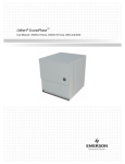
FIG. 1 shows a screen display presented to a user of
the graphic interface con?guration system and method
of the present invention;
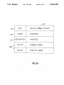
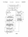
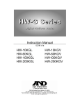
FIG. 2 shows another screen display presented to a
user of the graphic, interface con?guration system and
method of the present invention;
FIG. 3 shows another screen display presented to a
user of the graphic interface con?guration system and
method of the present invention;
FIG. 4 shows a portion of the screen display of FIG.
3;
FIG. 5 shows another form of the display of FIG. 4;
4
gram structure. How that knowledge is acquired will be
discussed below.
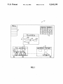
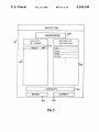
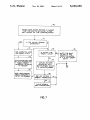
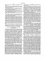
FIG. 1 is a diagrammatic representation of a com~
puter display that is seen when a user has entered the
graphic interface con?guration system of the invention,
has identi?ed to the system the program ?le for which
the interface is to be created, and has created the inter
face display screen. In this case, the user program,
named myProgram, is a simple program, as described
above, for taking two numbers, x and y, as inputs and
displaying their sum as the result, r.
As shown in FIG. 1, display 10 shows the interface
con?guration system menu 11 from which the user has
already selected the new application function, a palet
FIG. 5A shows a table of information stored in accor 15 te/toolbox 12 from which the user has selected a win
dance with the present invention;
dow, three boxes and a button, and a ?le window 13
FIGS. 6 and 6A (hereinafter collectively referred to
displaying information regarding ?les being worked on.
as FIG. 6) are a flow diagram of a portion of the process
implemented by another portion of the connection pro
Speci?cally, ?le window 13 contains a graphic element
130 representing myProgram, which has no visual
counterpart, a graphic element 131 representing my
Window, which is the window 14 being de?ned by the
user, and three graphic elements 132 in the shape of
suitcases which represent various ?le characteristics.
The user can open and close myWindow 14 by clicking
25 on its representation 131.
cess of the system and method of the present invention;
The user has de?ned myWindow 14 to contain a ?eld
implemented by the system and method of the present
invention when a user begins the connection process;
FIG. 7 is a ?ow diagram of a portion of the process
implemented by another portion of the connection pro
cess of the system and method of the present invention;
FIG. 8 is a flow diagram of a portion of the process
and
140 preceded by a text label ‘-‘x: ”, a ?eld 141 preceded
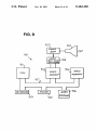
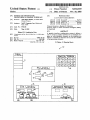
FIG. 9 is a block diagram of an exemplary hardware
by a text label “y: ”, a ?eld 142 preceded by a text label
con?guration for a computer on which the system and
“r: ”, and a button 143 labelled “+”. The program is
method of the present invention are implemented.
30 used by moving the pointer to ?eld 140 and clicking the
mouse button, thus allowing entry of the value x, then
DETAILED DESCRIPTION OF THE
doing the same with ?eld 141 to enter the value y, then
INVENTION
moving the pointer to button 143 and clicking, which
Although the graphic interface con?guration system
invokes the functional portion of myProgram, causing
of the present invention can be used on computers using 35 the sum of x and y to be displayed in ?eld 142.
any number of programming languages, it is best suited
In order to have the program work in this way, it is
to computers running object-oriented programming
necessary to link ?elds 140-142 to the variables in my
languages such as those described above, and the pre
Program representing x, y and r, and to link button 143
ferred embodiment of the invention is designed for a
to the functional portion of myProgram. In accordance
computer whose graphic interface is written in the ob 40 with the preferred embodiment of the present inven
tion, such linkage, or connection, is established as fol
ject-oriented C programming language. Therefore, the
discussion that follows will be tailored at least in part to
object-oriented programming, and to object-oriented C
programming in particular. It is to be understood, how
lows:
To link a ?eld to a variable in a program, the user
selects the program by moving the pointer 20 to the
ever, that the present invention is not limited to systems 45 representation of that program in ?le window 13 (al
that run object-oriented programming languages.
though not the case in FIG. 1, there maybe more than
The graphic interface con?guration system of the
one program from which to choose), and clicking the
present invention is a self-contained utility that is sepa
mouse button while holding down the control (CTRL)
rate from the underlying programs for which it is used
key on the computer ‘keyboard. While continuing to
to create interfaces. The underlying programs can be 50 hold the mouse button down (the control key can be
written before or after the interface is created, and are
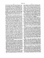
released), the user moves the mouse toward the ?eld of
generally capable of being executed without an inter
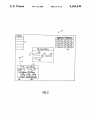
interest, drawing a line 21, as shown in FIG. 2, from the
face created by the present invention, or even without
program representation. When the line reaches the ?eld
any graphic interface at all.
of interest (e.g., ?eld 140) and the user releases the
A user of the present invention may invoke the 55 mouse button, the field is highlighted, as shown in FIG.
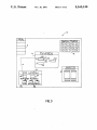
graphic interface con?guration system either before or. 3. At that point, a new window 30 appears on display
after the underlying program, an interface for which is
10, unless it was already present from a previous activ
to be created, has been written. If the program has not. ity. Window 30 is called the inspector window, and it is
been written, the present invention allows the user to
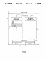
shown in more detail in FIG. 4. In this mode of opera
de?ne the existence of certain variables and functions 60 tion—-i.e., the linking or “connection” mode-the func
sufficiently to allow the user to construct the necessary
tion of inspector window 30 is to display the variables
graphic interface. At the same time it creates a skeletal
and function routines of the program to which graphic
program in which the variables and data structures are
elements are to be connected, and to facilitate the mak
de?ned, so that the user can go back afterwards and
ing of such connections.
de?ne the remainder of the program. The remainder of 65
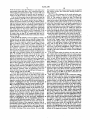
Inspector window 30 has a mode subwindow 400
the discussion will assume that the program has been
which displays the mode of operation of inspector win
written, and that the interface con?guration system of
dow 30, which has several different modes of operation.
the invention has available to it knowledge of the pro
As shown in FIG. 4, inspector window 30 is in the
5
5,163,130
connection mode. Inspector window 30 also has a com
ment subwindow 401 which displays different com
ments depending on the mode of operation and on what
portion of inspector window 30 is highlighted. Inspec
tor window 30 also has two “buttons” 402, 403 which
6
only variables (or “outlets”) can be connected to a pro
gram. Therefore, when an action is to be connected, it
must be connected through a special variable known as
“Target”, which is one of the variables that will be
displayed in subwindow 404 during the action connec
initiate functions when clicked on with the mouse. But
tion process, as shown in FIG. 5. The listing for the _
ton 402, labelled “Revert", has no function, and in fact
variable “Target” will be marked by an arrow 500
is disabled, in connection mode. Button 403, labelled
“Connect”, serves a connect/disconnect function, as
described in more detail below, in connection mode.
Finally, inspector window 30 has two subwindows 404,
405, respectively labelled “Outlets of Source” and “Ac
tions of Destination”, which respectively list the vari
pointing toward action subwindow 405, where various
possible actions, available through corresponding struc
tures in myProgram, are listed. To connect the action
“Plus” to button 143, the user highlights the variable
“Target”, then the action “Plus” and clicks on “Con
nect” button 403. As in the case of variables, an asterisk
or other flag (not shown) is displayed next to the name
ables and program function routines available for con
15 of a connected action, and when it is highlighted, "Con
nection.
nect” button 403 becomes a “Disconnect” button. Simi
With the variables of myProgram displayed in sub
larly, existing connections to a program will be dis
window 404, the user moves the pointer to the desired
played if a connected action is highlighted.
variable and clicks to highlight it (not shown). The user
In the case, referred to above, when a program al
then moves the pointer to the connect/disconnect but
ton 403, which is then labelled “Connect”, and clicks. 20 ready exists, its characteristics are made available to the
graphic interface con?guration system of the present
That establishes the connection between the variable
invention through a facility in the preferred embodi
and the ?eld in myWindow that is highlighted. At that
ment of the operating system known as the workspace
point, a flag, such as asterisk 406, appears next to the
manager. The workspace manager provides a window
variable name in subwindow 404, indicating that that
variable is connected and not available for other con 25 15, shown in FIG. 1, in which representations of various
available ?les are displayed. By highlighting representa
nections. At the same time, the label of the connect/dis
connect button changes to “Disconnect” (not shown).
If, when inspector window 30 is ?rst opened, there
tion 150 of myProgram', dragging it to File Window 13,
are already connected variables listed in subwindow
and dropping -it into that one of suitcases 132 labelled
“classes”, the user makes the characteristics of myPro
404 (from a previous connection operation), then aster
isk 406 will already be displayed for each connected
system.
variable, and if the user highlights a variable that is
already connected, a line like line 21 will be displayed,
showing the connection to myProgram. This allows
connections to be checked, either to make sure they are
correct, or to ?nd out what they are. If the user had
drawn line 21, intending to connect an unconnected
gram known to the graphic interface con?guration
-
When a graphic interface has been con?gured and the
user signi?es completion of the con?guration process
by selecting “Save” from menu 11, the graphic interface
con?guration system stores the graphic interface con
?guration in a ?le containing a list of all programming
objects related to the interface and a list of connections.
For each connection in the connection list, the system
stores as part of the graphic interface con?guration file
line between the ?eld to which that variable is con 40 a table 501 (shown in FIG. 5A) containing the type of
connection 502 (outlet or target-action), its source 503
nected and myProgram. In the preferred embodiment
(for an outlet) or destination 504 (for a target-action) in
line 21 has to be redrawn by the user before ?eld 140
the form of a pointer to the correct object in the object
can be connected to another variable, although it may
list, and the name 505 of the outlet variable or action
be possible to provide an “Undo” function that will
unhighlight the already connectedvariable and restore 45 object. When the con?guration ?le, including one or
more tables 501, has been saved, the work of the graphic
line 21 automatically. Again, whenever a connection is
interface con?guration system of the invention is com
displayed, button 403 will be labelled “Disconnect” and
plete.
the user has the option of clicking that button to discon
variable, but highlights a connected variable by mis
take, line 21 will disappear, and will be replaced by a
nect the variable or ignoring the Disconnect button and
choosing another variable.
The above process can be repeated until all ?elds are
connected to the desired variables. It is then necessary
to connect any action buttons, such as button 143, to the
When the user writes the program for which the
50 interface is constructed, whether before or after the
interface has been constructed, the ?rst line must be an
instruction to load and execute the graphic interface
con?guration ?le. Execution of the con?guration ?le
program structures that perform the desired functions.
loads the correct ?les, makes the appropriate connec
Program in ?le window 13 which becomes highlighted
program representation such as graphic element 130, or
Such connections are established by a process that is 55 tions (based in part on the tables 501), and displays the
correct windows and other graphic elements, so that
similar to that for linking ?elds to variables, except that .
the end user of the program is faced only with the inter
instead of positioning the pointer over the program
face.
representation in ?le window 13 and drawing a line to
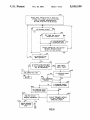
FIG. 6 is a flow diagram of a routine (hereinafter
the desired ?eld, one starts with the pointer on the
desired button. Again, the mouse button is held down 60 referred to as the main connection routine) which is
invoked, at step 60, when a user presses a mouse button
while CTRL is being pressed and a line is drawn (not
while the CTRL key is down and pointer 20 is over a
shown) from button 143 to representation 130 of my
over a screen button object such as button 143. At test
61, the system checks to see if the pointer has moved. If
65
In this case, the display in inspector window 30 is
as did ?eld 140 in the process described above.
slightly different, as shown in FIG. 5. The user is really
interested in connecting an action to myProgram. How
ever, in the preferred embodiment of the invention,
the pointer has moved, then at test 62, the system tests
to see if there are pre-existing connecting lines. If there
are pre-existing connecting lines, they are removed
7
5,163,130
8
from the screen at step 63. Whether or not there were
the pointer is over the connect button, then at step 617
preexisting connecting lines, new connecting lines be
the system invokes the connection making routine of
FIG. 8, below.
tween program representation 130, or button 143, and
pointer 20 are displayed at step 64, and the system re
turns to test 61 to check for further pointer movement.
If at test 61 the pointer has not been moved, then the
system checks at test- 65 to see if the mouse button has
been released. If the mouse button has not been re
leased, the system returns to test 61 to continue check
ing for pointer movement. If at test 65 the mouse button
has been released, then at test 66 the system checks to
see if the pointer is over a type of object to which the
program represented by element 130 (if the connecting
line starts there) or the button depicted at 143 (if the
connecting line starts there) can be connected. If the
pointer is not over an object to which a connection can
be made, then at step 67 all connecting lines are re
moved from the screen and the main connection routine
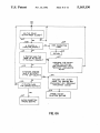
FIG. 7 is a flow diagram of the outlet selection rou
tine referred to above, which is invoked at step 615 in
FIG. 6. The routine is entered at step 70 when the
mouse button is clicked while the pointer is over the
name of an outlet in the left-hand column of the inspec
tor window. The system checks at test 71 to see if the
outlet that the pointer is over is already connected to a
screen object. If the outlet that the pointer is over is
already connected to a screen object, then any connect
ing lines and frame that may be visible are removed
from the screen at step 72, new connecting lines be
tween the program and the screen object connected to
the outlet are displayed at step 73, and a frame is drawn
around the object connected to the outlet at step 74.
From step 74, or if at test 71 the outlet that the pointer
ends at step 68.
is over is not already connected to a screen object, the
If at test 66, the pointer is over an object to which a 20 system proceeds to test 75 to see if the outlet the pointer
connection can be made, then at step 69 a frame is dis
is over is the “target” outlet. If the outlet the pointer is
played around the object and the system checks at test
over is not the “target” outlet, then no actions should be
600 to see if the inspector window is visible. If the in
visible in the right-hand column of the inspector win
spector window is not visible, it is made visible at step
dow, and at step 76 any actions that may have been
601, and in any event the system checks at test 602 to see 25 visible in the right-hand column of the inspector win
if the inspector window is in the connection mode. If
the inspector window is not in the connection mode,
then it is set to the connection mode at step 603, and in
dow from a previously highlighted “target” outlet are
any event the available program outlets are displayed at
mouse clicks.
step 604 in the left-hand column of the inspector win
dow. At test 605, the system tests to see if any of the
If at test 75 the outlet the pointer is over is the “tar
get” outlet, then at step 77 any action or actions associ
displayed outlets are already connected. If any of the
displayed outlets are connected, then at step 606 an
asterisk is displayed next to each one that is connected,
played in the right-hand column of the inspector win
removed from the screen. The system then returns to
test 607 of the main connection routine to await further
ated with the button highlighted on the screen are dis
dow. At test 78, the system tests to see if any of the
and in any event the system checks at test 607 to see if 35 displayed actions are already connected to other pro
the mouse button has been clicked. If the mouse button
gram segments. If none of the displayed actions are
has not been clicked, the system continues to test for a
already connected to other program segments, then the
click at test 607. If the mouse button has been clicked,
system returns to test 607 of the main connection rou
then the system checks at test 608 to see if the pointer is
tine to await further mouse clicks. If any of the dis
within the inspector window. If the pointer is not within 40 played actions are already connected to other program
the inspector window, then all connecting lines are
segments, then at step 79 an asterisk is displayed next to
removed from the screen at step 609 and the main con
the name of each action so connected, and then the
nection routine ends at step 610.
system returns to test 607 of the main connection rou
If at test 608 the pointer is within the inspector win
time to await further mouse clicks.
dow, then the system checks at test 611 to see if the 45
FIG. 8 is a flow diagram of the connection making
pointer is over the name of an action in the right-hand
routine referred to above, which is invoked at step 617
column of the inspector window. If the pointer is over
in FIG. 6. The routine is entered at step 80 when the
the name of an action in the right-hand column of the
mouse button is clicked while the pointer is over the
inspector window, then at step 612 the action under the
connect button. At test 81, the system checks to see if
pointer is highlighted and any previously highlighted
there is a selected outlet. If there is no selected outlet,
action is unhighlighted, and the system returns to test
then the system returns to test 607 of the main connec
607 to check for further clicking of the mouse button. tion routine to await further mouse clicks. If at test 81
If at test 611 the pointer is not over the name of an
i there is a selected outlet, the system checks at test 82 to
action in the right-hand column of the inspector win
see if the selected outlet is the “targe ” outlet. If the
selected outlet is not the “target” outlet, then at test 83
pointer is over the name of an outlet in the left-hand .
the system checks to see if the outlet is already con
column of the inspector window. If the pointer is over
nected. If the outlet is already connected, then at step 84
the name of an outlet in the left-hand column of the
the outlet is disconnected from the highlighted screen
inspector window, then at step 614 the outlet under the
object and the asterisk is removed from next to the
pointer is highlighted and any previously highlighted 60 name of the outlet in the left-hand column of the inspec
outlet is unhighlighted, and at step 615 the system in
tor window. The label of the connect button is then
vokes the outlet selection routine of FIG. 7, below. If at
changed to “Connect” at step 85, and then the system
dow, then at test 613 the system checks to see it‘ the
test 613, the pointer is not over the name of an outlet in
the left-hand column of the inspector window, then at
returns to test 607 of the main connection routine to
await further mouse clicks. If at test 83 the outlet is not
test 616 the system checks to see if the pointer is over 65 already connected, then at step 86 the outlet is con
the connect button. If the pointer is not over the con
nected to the highlighted screen object and an asterisk is
nect button, then the system returns to test 607 to check
displayed next to the name of the outlet in the‘left-hand
for further clicking of the mouse button. If at test 616
column of the inspector window. The label of the con
9
5,163,130
10
memory, although more or less memory may suitably
nect button is then changed to “Disconnect” at step 87,
and then the system returns to test 607 of the main
be used. Video memory 903 comprises 256K bytes of
connection routine to await further mouse clicks.
conventional dual-ported video random access mem
ory. Again, depending on the resolution desired, more
If at test 82 the outlet is the “target” outlet, then at
test 88 the system checks to see if there is a highlighted
action in the right-hand column of the inspector win
or less such memory may be used. Connected to a port
of video memory 903 is video multiplex and shifter _
dow. If there is not a highlighted action in the right
circuitry 908, to which in turn is connected video ampli
?er 909. Video ampli?er 909 drives cathode-ray tube
(CRT) raster monitor 910. Video multiplex and shifter
hand column of the inspector window, then the system
returns to test 607 of the main connection routine to
await further mouse clicks. If there is a highlighted
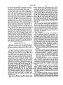
circuitry 908 and video ampli?er 909, which are con
ventional, convert pixel data stored in video memory
903 to raster signals suitable for use by monitor 910.
action in the right-hand column of the inspector win
dow, then at test 89 the system checks to see if the
Monitor 910 is of a type suitable for displaying graphic
images having a resolution of 1120 pixels wide by 832
highlighted action is associated with a program-button
connection through the “target" outlet. If the high
lighted action is associated with a program-button con 15
pixels high.
Thus it is seen that a graphic interface con?guration
nection through the “target” outlet, then at step 800 the
utility is provided that allows graphic elements in the
“target” outlet is disconnected and the asterisk next to
the name of the associated action in the right-hand col
umn of the inspector window is removed from the
screen. The label of the connect button is then changed
to “Connect” at step 85, and then the system returns to
test 607 of the main connection routine to await further
mouse clicks. If at test 89 the highlighted action is not
interface to be linked to variables or functions in any
one of a number of programming elements. One skilled
in the art will appreciate that the present invention can
be practiced by other than the described embodiments,
which are presented for purposes of illustration and not
of limitation, and the present invention is limited only
by the claims which follow.
associated with a program-button connection through
the “target” outlet, then at step 801 a “target” outlet 25 What is claimed is:
1. In a computer system having a visual display on
program connection is made, the highlighted action is
which an application program is represented by a
associated with that connection, an asterisk is displayed
graphic image, said application program having at least
next to the name of the action in the right-hand column
one program routine having variables and action por
of the inspector window, and any other asterisks in the
right-hand column of the inspector window are re 30 tions, said application program being executed through
a graphical program interface that provides a program
moved from the screen. The label of the connect button
window on said display, said program window contain
is then changed to “Disconnect” at step 87, and then the
ing graphic elements representing user inputs and out
puts, said graphic image and graphic elements being
system returns to test 607 of the main connection rou-'
tine to await further mouse clicks.
HARDWARE SYSTEM
While the present invention may advantageously be
implemented on nearly any conventional computer
35 capable of being moved on said display by a suer, a '
graphical program interface con?guration system for
allowing a programmer to de?ne said graphical pro
system, an exemplary computer system 900 on which
gram interface, said system comprising:
programmer-controllable graphical de?nition means
the present invention is implemented is shown in FIG.
for allowing a programmer to de?ne said program
window;
programmer-controllable graphical placement means
9.
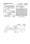
FIG. 9 shows a preferred embodiment of a hardware
for for allowing a programmer to place at least one
system 900 implementing the present invention as part
of said graphic elements in said program window;
of a computer system. In FIG. 9, system 900 includes
CPU 901, main memory 902, video memory 903, a key 45 programmer-controllable graphical connection
means for allowing a programmer to logically des
board 904 for user input, supplemented by a conven
ignate any of said at least one graphic element as an
tional mouse 905 for manipulating graphic images ac
input/output element for any one of said at least
cording to the present invention, and mass storage 906
one program routine.
which may include both ?xed and removable media
using any one or more of magnetic, optical or mag 50 2. The graphical program interface con?guration
system of claim 1 wherein said at least one graphic
netooptical, storage technology or any other available
element represents an input ?eld for a variable, and said
mass storage technology. These components are inter
programmer-controllable graphical connection means
. connected via conventional bidirectional system bus
907. Bus 907 contains 32 address lines for addressing
any portion of memory 902 and 903. System bus 907 55
also includes a 32 bit data bus for transferring data be-.
tween and among CPU 901, main memory 902, video
memory 903, and mass storage 906. In the preferred
embodiment of system 900, CPU 901 is a Motorola
68030 32-bit microprocessor, but any other suitable
microprocessor or microcomputer may alternatively be
used. Detailed information about the 68030 micro
processor, in particular concerning its instruction set,
bus structure, and control lines, is available from
MC68030 User’s Manual, published by Motorola Inc.,
of Phoenix, Ariz.
Main memory 902 of system 900 comprises eight
megabytes of conventional dynamic random access
65
is for logically designating said graphic element as an
input/output element for a variable in said program
routine.
3. The graphical program interface con?guration
system of claim 1 wherein said at least one graphic
element represents an action for selection by a user, and
said programmer-controllable graphic connection
means is for logically designating said graphic element
as an input element for an action portion in said pro
gram routine.
4. The graphical program interface con?guration
system of claim 1 wherein said programmer-controlla
ble graphical connection means comprises means for
graphically displaying a logical designation established
between said graphic element and said program routine.
11
5,163,130
12
5. The graphical program interface con?guration
allowing a programmer to de?ne said graphical pro
system of claim 4, wherein said programmer-controlla
gram interface, said method comprising the steps of:
ble graphical connection means further comprises
allowing a programmer to graphically de?ne said
means for graphically highlighting said graphic element
window;
and said program routine while said logical designation 5
allowing a programmer to graphically place at least
is displayed.
'
one of said graphic elements in said window;
6. The graphical program interface con?guration
allowing a programmer to graphically logically des
system of claim 4, wherein said graphical connection
ignate any of said at least one graphic element as an
means further comprises means for graphically display
ing said variables and said action portions for which
input/output element for any one of said at least
one program routine.
said graphical element can be designated as an input
13. The graphical program interface con?guration
/output element.
7. The graphical program interface con?guration
method of claim 12 wherein said at least one graphic
element represents an input ?eld for a variable, and said
system of claim 6, wherein said graphical variable and
graphical logical designation step is for logically desig
action portion display means comprises means for in 15 nating said graphic element as an input/output element
dicting if any one of said variables and action portions
for a variable in said program routine.
has a graphic element logically designated as an input
14. The graphical program interface con?guration
/output element therefor.
method of claim 12 wherein said at least one graphic
8. The graphical program interface con?guration
element represents an action for selection by a user, and
system of claim 6 wherein said graphical variable and 20 said graphical logical designation step is for logically
action portion display means comprises means for se
designating said graphic element as an input element for
lecting one of said displayed variables and action por
an action portion in said program routine.
15. The graphical program interface con?guration
method of claim 12 wherein said graphical designation
tions.
9. The graphical program interface con?guration
system of claim 8 wherein said graphical variable and 25 step comprises graphically displaying a logical designa
action portion display means comprises actuation means
tion established between said graphic element and said
for (a) if a selected one of said displayed variables and
program routine.
'
‘
action portions does not have a graphic element logi
16. The graphical program interface con?guration
cally designated as an input/output element therefor,
method of claim 15, wherein said graphical designation
logically designating said graphic element as an input 30 step further comprises graphically highlighting said
/output element for said selected one of said displayed
graphic element and said program routine while said
variables and action portions, and (b) if a selected one of
logical designation is displayed.
said displayed variables and action portions has a
graphic element logically designated as an input/output
17. The graphical program interface con?guration
method of claim 15, wherein said graphical designation
element therefor, cancelling logical designation of said
35
step further comprises graphicallyv displaying said vari
graphic element as an input/output element for said
selected one of said displayed variables and action por
ables and said action portions for which said graphical
tions.
ment.
element could be designated as an input/output ele
'
10. The graphical program interface con?guration
18. The graphical program interface con?guration
system of claim 9 wherein said programmer-invocable 40 method of claim 17, wherein said graphical variable and
actuation means changes its appearance according to
action portion displaying step comprises indicating if
whether or not said selected one of said displayed vari
any one of said variables and action portions has a
ables and action portions has a graphic element logi
graphic element logically designated as an input/output
cally designated as an input/output element therefor.
element therefor.
11. The graphical program interface con?guration 45 19. The graphical program interface con?guration
system of claim 8 wherein said programmer-controlla
method of claim 17 wherein said graphical variable and
ble graphical connection means comprises means for, if
action portion displaying step comprises selecting one
a selected one of said displayed variables and action
of said displayed variables and action portions.
portions is subject to a pre-existing logical designation
20. The graphical program interface con?guration
of a second graphic element in said program window as 50 method of claim 19 wherein said graphical variable and
an input/output element therefor, terminating the
action portion displaying step comprises an actuation
graphical display of an attempted logical designation
step of (a) if a selected one of said displayed variables
and action portions does not have a graphic element
logically designated as an input/output element there
established between said graphic element and said one
of said variables and action portions and graphically
displaying said pre-existing logical designation between
said second graphic element and said one of said vari- .
ables and action portions.
12. For use in a computer system having a visual
_ display on which an application program is represented
for, logically designating said graphic element as an
input/output element for said selected one of said dis
played variables and action portions, and (b) if a se
lected one of said displayed variables and action por
tions has a graphic element logically designated as an
by a graphic image, said application program having at 60 input/output element therefor, cancelling logical desig
least one program routine having variables and action
nation of said graphic element as an input/output ele
ment for said selected one of said displayed variables
and action portions.
portions, said application program being executed
through a graphical program interface that provides a
program vwindow on said display, said program window
containing graphic elements representing user inputs
and outputs, said graphic image and graphic elements
being capable of being moved on said display by a user,
a graphical program interface con?guration method for
65
21. The graphical program interface con?guration
method of claim 19 wherein said graphical designation
step comprises, if a selected one of said displayed vari
ables and action portions is subject to a pr'e-existing
logical designation of a second graphic element in said
13
5,163,130
14
and graphically displaying said pre-existing logical des
program window as an input/output element therefor,
terminating the graphical display of an attempted logi
ignation between said second graphic element and said
cal designation established between said graphic ele
one of said variables and action portions.
ment and said one of said variables and action portions
t
10
15
20
25
35
45
55
65
t
t
t
it
UNITED STATES PATENT AND TRADEMARK OFFICE
CERTIFICATE OF CORRECTION
DATED
2
|NVENTOR(S) I
NOV. 10, 1992
Jean-Marie Hullot
It is certified that error appears in the above-indenti?ed patent and that said Letters Patent is hereby
corrected as shown below:
Item [57] Abstract, line 1 , "is" should be deleted.
Column 1,
line 6,
"abandoned" should be -— now abandoned, ——.
Column 3, line 7, "graphic," should be -- graphic ——.
Claim 1, column 10, line 35,
"suer," should be —— user, -—;
column 10, line 43, "for" (second occurrence) should
be deleted.
Claim 3, column 10, line 60, "graphic" should be
-—
graphical
——.
Signed and Sealed this
Twelfth Day of April, 1994
Arrest:
(Lemme
BRUCE LEEMAN
Arresting Officer
Commissioner of Patents and Trademarks