1
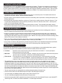
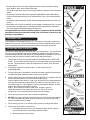
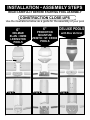
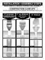
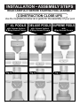
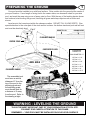
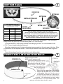
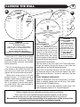
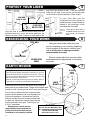
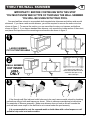
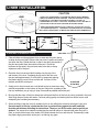
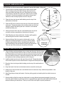
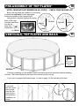
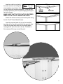
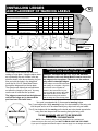
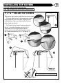
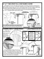
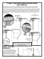
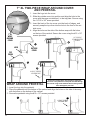
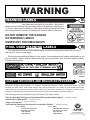
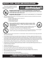
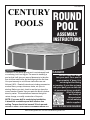
Part# 420363-16
CENTURY
ROUND
POOLS
POOL
ASSEMBLY
INSTRUCTIONS
GENERAL
Installation of this above ground pool is not extremely hard
or confusing, but it is a big job. The secret to installing a
pool so that it will give you years of pleasure is to take the
time to follow instructions and do things right the first time.
Your pool warranty is void if these instructions are not
followed 100%. Read all instructions including accessories
such as filters, pumps, skimmers, decks, etc. prior to
starting. Before you start, check to see that you have the
correct number of parts. Use your parts list which is broken
down by carton. The manufacturer reserves the right to
revise, change, or modify construction of its pools.
NOTE: If a power drill is used during installation,
it should be a variable speed drill used on low
setting. Torque should not exceed 39 inch pounds.
FAILURE TO COMPLY COULD RESULT IN SCREWS STRIPPING OUT.
DANGER
DO NOT DIVE OR JUMP
into your pool. Your pool is
approximately 4' deep. It is
not designed for diving
or jumping. If you dive or jump
into your pool you run the risk
of permanent injury or death.
Alert all visitors
and family of
this and point
out all warning
labels supplied.
ADULT SUPERVISION REQUIRED
www.century-pools.com • E-mail: [email protected]
CONTRACT INSTALLATIONS
The manufacturer is in no way affiliated with any professional pool installer. Therefore the manufacturer can assume no
responsibility for errors in installation by the home owner or said professional installer. If you have your POOL installed
by others, please supervise them to be sure they comply with the proper installation techniques shown. Their past experience or short cuts may not cover the latest improvements in our POOLS. Do not allow any short cuts of any nature.
LOCAL CODES
• Local building code may require obtaining a building permit and or an electrical permit. The installer shall follow the
regulations on set backs, barriers, devices and other conditions.
• Any after market or home built deck should be built to the local building code requirements, including load capacity and
fencing requirements.
• All electrical outlet connections should be a minimum of 5 feet from the outside perimeter of the wall of the pool. From
5-10 feet there should be either a fixed connection (outlet box) or twist lock connection with a GFCI. Connect power
cords to a 3-wire grounding-type outlet only.
• Severe electrical shock could result if you install your pump or filter on a deck. They could fall into the water, causing
severe shock or electrocution. Do not install on a deck or other surface at, above or slightly below the top ledge of the pool.
BARRIER REQUIREMENTS
• If the distance from the top of the assembled pool is less than 48" vertically from the surrounding grade, a fence or
barrier is needed to surround the pool with a minimum height of 48".
• A barrier is necessary to provide protection against potential drowning and near drowning and is not a substitute for
constant supervision of children. A barrier is a fence, wall, or a combination thereof which completely surrounds the
swimming pool and obstructs access to the swimming pool. Barriers must comply with local and national building codes
and the US Consumer Product Safety Commission.
• These are minimum fencing and barrier requirements. Check your local building codes for other requirements they
may request. Optional fencing kits are available, Please contact your local dealer.
• If pool covers are used for safety barriers they should comply with ASTM F 1346 "Standard Performance Specification
for Safety Covers and Labeling Requirements for All Covers for Swimming Pools, Spas and Hot Tubs."
SPECIAL CARE
Even though this manufacturer's pools are designed to meet or exceed industry recommended safety factors, special
attention must be paid to some installation procedures that the installer performs and controls.
•
Levelness
Spend the time to assure that the entire pool framework is level within 1". Unlevel pools place
extreme pressures on the pool walls.
•
Wall seam
This area is where the wall joins together. Damage to any part of this area reduces the safety factors
and can result in a weak pool. Use extreme care following instructions.
•
Earth mound
This keeps the liner from creeping out from under the pool wall. Follow instructions to the letter
– don't short-cut or substitute materials. Improperly installed pools can rupture, allowing thousands
of gallons of water to rush out causing extensive property damage and injury to anyone in its path.
• This manufacturers pools are not designed to be buried. Outside ground forces can collapse pool wall. Certain
conditions may exist, like the levelness of the pool area that require the pool to be recessed. You must maintain a
finished pool height of 36” above ground level. If your pool is 48” deep, you may recess the pool by 12” (48”-36”=12”).
Consult your local pool professional and building codes as to the use of earth retaining walls to recess your pool deeper
than this recommended amount. Make sure that the pool remains full of water for at least 7 days before backfilling the
pool recess. Place a layer of plastic film against the pool before backfilling to protect the pool from corrosion agents that
may be found in the backfill materials.
• The pool owner has the sole responsibility for providing adequate lighting for the pool area.
• All users must be able to see the shallow depth of the pool, and safety signs at all times.
• You must install a pool ladder(s) and/or steps for entry and exit from the pool.
• The use of artificial pool lighting is at the discretion of the pool owner.
• All electrical components shall be installed in accordance with Article 680 of the National Electrical code 1999 (NEC®)
“Swimming Pools, Fountains and Similar Installations” or its latest approved edition.
2
• During night time pool use, artificial lighting shall be used to illuminate all safety
signs, ladders, steps, deck surfaces and walks.
• The installer shall follow written instructions provided for operation of the circulation
system.
• Decks shell meet local codes and comply with ANSI/NSPI-8 1996 “Model Barrier
Code for Residential Swimming Pools, Spas and Hot Tubs” or the latest approved
edition.
Screwdriver
Hammer
• Underwater lights having front access shall be installed and removed only with use
of tools.
• The installer of the vinyl liner shall affix on the original or replacement liner, or on the
pool structure, all safety signs in accordance with the manufacturer’s instructions.
The safety signs shall be placed above the water line.
Tape
All components such as the filtration system, pumps and heater shall be
positioned so as to prevent their being used as a means of access to the
pool by young children.
Hoe
Knife
INTRODUCTION
The installation of an average size pool (12' - 30' diameter) will usually require three
people to help set it up. Listed is an assortment of tools and materials which you will
need for preparing the ground, checking the levelness, and setting up the pool.
SELECTING POOL LOCATION
Rake
Shovel
4” Nail
The selection and preparation of the pool site is your responsibility. The manufacturer
can only suggest the proper techniques, indicate the important considerations and
emphasize the precautions, and cannot be held responsible for damages to your pool
that may result from failure to carefully follow all pool site specifications.
1.
The surface on which your pool will stand must be ABSOLUTELY LEVEL AND
SOLID. This condition should extend one (1) foot beyond the actual pool area all
around. The best surface is bare solid earth free from stones, roots, and other
sharp objects.
Broom
Pliers
Patio Blocks
2.
Allow plenty of play area around the pool. Fit the location into your
landscaping plans.
3.
The pool site must be accessible to electrical and water supply and should allow
for disposal of great quantities of water when pool is drained.
4.
When installing your pool on a SOLID LEVEL SURFACE, it is imperative that you
protect your pool and liner from chemicals and other foreign
matter contained in the surface. Protect your pool and liner by inserting between
them and the surface any material that is not made from a tar derivative or contains sharp twigs, etc. We suggest the use of a plastic ground shield to be used
between the surface and the pool liner (See
step 2). Do not install your pool on peat moss, tar paper, gravel or
chemically treated soil not approved for pool use. Any or all of these
surfaces can ruin your pool and liner and will void your warranty.
5.
Do not set up your pool under trees or under overhead wires.
6.
DO NOT set up your pool near any existing structure such as your house garage,
etc., as this condition will induce diving or jumping into your pool which could
result in permanent injury or death.
7.
Do not set up your pool on or near any septic system or underground utilities.
8.
Choose your pool location convenient for:
a. Connecting electrical wires of your accessories (filter, heater, lights) to
your electrical outlets conforming to electrical codes.
b. Draining large amounts of water.
Carpenters
Level
Cloth Tape
2x4
Center
Stake
Sifted Earth
or Pre
Washed
Sand
SOME FRIENDS
TO HELP OUT
3
INSTALLATION • ASSEMBLY STEPS
READ CAREFULLY BEFORE STARTING POOL ASSEMBLY
CONSTRUCTION CLOSE-UPS
Use the illustrations below as a guide for the assembly of your pool
6”
6”
DELUXE POOLS
DELMAR
ELAN • OMNI
LEXINGTON
POOLS
PRINCETON
QUANTUM
ZENITH • ST. CROIX
POOLS
with Box Vertical
OPTIONAL
Fig. A
4
Fig. B
Fig. C
INSTALLATION • ASSEMBLY STEPS
READ CAREFULLY BEFORE STARTING POOL ASSEMBLY
CONSTRUCTION CLOSE-UPS
Use the illustrations below as a guide for the assembly of your pool
6” EXTRUDED
ALUMINUM POOLS
with Box Vertical
Fig. D
7” XL POOLS
with Column
Vertical
Fig. E
9” POOLS
Fig. F
5
INSTALLATION • ASSEMBLY STEPS
READ CAREFULLY BEFORE STARTING POOL ASSEMBLY
CONSTRUCTION CLOSE-UPS
Use the illustrations below as a guide for the assembly of your pool
7” XL POOLS DELUXE POOLS SUPREME POOLS
6
with Column Vertical
& Wrap Around Covers
with Column Vertical
& Wrap Around Covers
with
Wrap Around Covers
Fig. G
Fig. H
Fig. I
PREPARING THE GROUND
1
Your pool must be installed on a solid level surface. Drive a stake into the ground at the center of
your pool location. Use a length of string tied to the center stake, see clearance chart for your size
pool, and mark the area using a can of spray paint or flour. With the use of the leveling device shown
and a shovel, start leveling the ground, removing all grass and sharp objects such as sticks and
stones.
Level area to the lowest spot within the clearance radius. DO NOT FILL IN LOW SPOTS. Give
special attention to the outer part of the circle as this is where the bottom track and pool wall will rest
and must be absolutely level.
2”x 4”
DO NOT FILL IN
NAIL
DIG AWAY HERE
CLEARANCE RADIUS
CENTER STAKE
CARPENTER’S LEVEL
CLEARANCE
RADIUS=1/2
POOL DIAMETER + 6"
LEVEL AREA
CLEARANCE RADIUS
The assembled pool
must have a vertical
distance of 3' from the
top of the pool to the
adjoining grade and
the adjoining grade
must remain level for
a distance of 4' away
from the pool. Refer to
the drawing at right.
12' Pool
15' Pool
18' Pool
21' Pool
24' Pool
27' Pool
30’ Pool
=
=
=
=
=
=
=
6' 6"
8'
9' 6"
11'
12' 6"
14'
15’ 6”
3 FT.
4 FT.
PREVIOUS GRADE
WARNING - LEVELING THE GROUND
THIS IS THE MOST IMPORTANT PART OF YOUR PREPARATION OF POOL SITE.
YOU MUST GIVE CAREFUL ATTENTION TO THIS PHASE.
REMEMBER — YOUR POOL MUST BE INSTALLED ON SOLID LEVEL SURFACE.
7
BOTTOM RAILS
2
CENTER STAKE
BOTTOM RAIL
BOTTOM RAIL
VERTICAL BOTTOM PLATE
PRE WASHED SAND OR
SIFTED EARTH RECOMMENDED
REQUIREMENT CHART
12 ft.
1.4 Tons
1.1 Yards
15 ft.
1.9 Tons
1.5 Yards
18 ft.
2.6 Tons
2.1 Yards
21 ft.
3.4 Tons
2.7 Yards
24 ft.
4.4 Tons
3.5 Yards
27 ft.
5.4 Tons
4.3 Yards
30 ft.
6.5 Tons
5.2 Yards
OPTIONAL
GROUND SHIELD
BOTTOM PLATE
PATIO BLOCK
1/16”
Ground Shield and Wall Guard are optional.
Spread a ground shield or plastic sheeting over prepared ground
(not included). Ground Shield and Wall Guard are available from your
local pool supply dealer or polyethylene sheeting can be purchased
from a local hardware supply. This will protect your pool liner and
metal parts against chemical reactions from the ground soil.
Mark out pool radius (1/2 pool diameter) using the center stake as reference. Form a circle by
sliding bottom rail groove up, into the bottom plates 1/16" from the stop.
To prevent stones or other foreign material from damaging the liner it is recomended to build
a 2” to 3” base of sand inside the entire pool.
Bring the required amount of clean and washed masonry sand into the pool area at this time. Refer
to chart above for the required amount. Place the patio blocks under each bottom plate at ground
level.
Check the levelness from the center stake to each bottom plate.
INSERT WALL INTO BOTTOM RAILS
SKIMMER INLET
SKIMMER OUTLET
8
3
Remove wall from carton.
NOTE: the UP arrow on wall.
Determine starting point as the
filter inlet and outlet holes are at
the beginning of the wall. Starting
at the center of a bottom plate
insert the bottom edge of the
wall into the groove
on the bottom rail.
Ensure that the center line of the closure
holes in the the wall align with the center
of the plate. Make sure that the cutouts
4’ x 4’ Plywood
for filter inlet and outlet are on the top portion of the wall and will not be hidden behind
a vertical. If the wall ends do not meet, adjust
the bottom rail in or out of the bottom plates. The
spacing in all bottom plates should be equal.
CLOSING THE WALL
A
4
3/8" TRUSS
HEAD SCREW
1/4" x 20 x 3/4"
TRUSS HEAD
4 CLOSURE
SCREW
INSIDE
OF POOL
1/4" x 20
SERRATED
FLANGE NUT
Wall
Pool
B
WASHER
BARS
View from
the top
Wall
Pool
Wall
Pool
WASHER
3/8 FLANGE
NUT
DANGER
DANGER
YOU MUST ASSEMBLE THE POOL WALL
AS PER INSTRUCTIONS
USE ALL THE 1/4"-20x3/4" TRUSS HEAD
SCREWS AND 1/4"-20 SERRATED FLANGE
NUTS TO CLOSE POOL WALL.
DO NOT LEAVE ANY OPEN HOLES
TIGHTEN EACH SCREW TO 85 INCH POUNDS.
Insert the 1/4" - 20x3/4" truss head
screws from inside the pool through the
preattached inside closure bar, through
inside and outside wall ends, and through
outside closure bar.
The 1/4" serrated flange nuts are secured
to the screws on the outside of the wall. All
the holes must match and be secured
together with the screws and nuts provided.
Tighten each screw and nut to 85 inch
pounds of torque. If no torque wrench is
available, tighten each nut until snug. Then
tighten each nut one (1/2) half
additional
turn. If nut appears to be lose after tightening, please check if the screw is stripped or
broken. It must be replaced.
Recessed
Posi-Lock System
During this assembly procedure,
make sure that one washer is on
the inside of the pool, and one
washer in on the outside of the
pool sandwiching the two wall
ends between them. Also ensure
that the recesses of the walls and
washers all face the same direction.
YOU MUST ASSEMBLE THE
POOL WALL
AS PER INSTRUCTIONS
USE ALL THE 3/8-16x3/4"
TRUSS HEAD SCREWS,
WASHERS AND 3/8-16
SERRATED FLANGE NUTS
TO CLOSE POOL WALL.
DO NOT LEAVE ANY
OPEN HOLES
TIGHTEN EACH SCREW
TO 85 INCH POUNDS.
Align the holes in the wall ends.
From the inside of the pool, insert a 3/8 Truss Head screw
through the washer, through the holes on the inside and
outside wall ends, and through the second washer.
Fasten with 3/8 serrated flange nut on the outside of the
pool having the flange of the nut face the washer. Only hand
tighten the nuts at this point. Continue for each hole in the wall
ends.
DO NOT LEAVE ANY OPEN HOLES.
Tighten all screws and nuts to 85 inch pounds. If no torque
wrench is available, tighten each nut until snug. Then tighten
each nut one half (1/2) additional turn.
If nut appears to be lose after tightening, please check if the
screw is stripped or broken. If it is, it must be replaced.
Overtightening the nuts could cause the screws to fracture which could result in pool failure.
Failure to tighten the nuts sufficiently could also result in pool failure.
This is one of the most important structural assembly aspects you will perform.
Be absolutely sure you have assembled the wall as shown above for your pool.
Manufacturer can not assume the responsibility of the performance of this product if the
instructions of closing the wall are not followed exactly.
9
PROTECT YOUR LINER
WALL
SEAM
INSIDE OF
POOL VIEW
5
SKIMMER
RETURN FITTING
VIEW FROM
INSIDE OF POOL
SKIMMER
INLET FITTING
3 LAYERS
OF TAPE
way from top to bottom of wall. If the filter inlet and
outlet are not used, cover over the pre-scored areas
on the inside of the pool wall with 1 layer of tape.
If your Pool Wall has the
Recessed Posi-Lock System an
additional layer of tape should be
added to the inside part of the
extended end of the wall.
WALL
SEAM
CLOTH TAPE
OR DUCT TAPE
3 LAYERS
OF TAPE
INSIDE OF
POOL VIEW
Once the wall is closed and screws and nuts are
tightened securely, cover the screw heads on the
inside of the pool with 3 layers of cloth tape all the
EXTENDED
END OF WALL
Cloth tape or duct tape is
available through your local
pool dealer or hardware
store.
RECHECKING YOUR WORK
POOL WALL
Using the center stake make sure your
pool is completely in true round by measuring
from the center of the stake to inside of pool
wall in all directions, making sure these
measurements are equal.
IUS
RAD
CENTER STAKE
6
VIEWED FROM
ABOVE
Remove center stake from pool area after
measurements and adjustments, if necessary,
are made.
EARTH MOUND
7
OPTIONAL
WALL
GUARD
Wall guard is optional.
Tape wall guard (plastic sheeting) to pool wall 12" up from
ground and smooth out on ground 12" from wall. This will
protect your pools metal parts from chemical reactions with
the soil used in the earth mound.
Several commercial products can also be used in place of
earth mound. Consult your professional pool dealer.
8”
Build earth mound on top of wall guard using screened
damp earth or pre-washed sand. Shape and compact earth
mound to run 8" up from ground and 8" away from the wall.
Do not use any material that will compress under
pressure for the earth mound is an important part
of the pool installation. It prevents the wall from
lifting up and the liner from sneaking underneath
the pool wall. Spread the remaining sand equally
across the bottom of the pool. This will give you
a 2“ to 3” sand base.
Manufacturer cannot assume
responsibility of the performance
of this product if the earth mound
is omitted or not properly installed.
10
EARTH
MOUND
12”
DANGER
DO NOT USE ANY MATERIAL THAT
WILL COMPRESS UNDER PRESSURE
FOR THE EARTH MOUND.
SEE INSTRUCTIONS TO LEFT.
12”
8”
THRU-THE-WALL SKIMMER
8
IMPORTANT!! BEFORE CONTINUING WITH THIS STEP
YOU MUST KNOW WHICH TYPE OF THROUGH THE WALL SKIMMER
YOU WILL BE USING WITH YOUR POOL
Your pool wall has cutouts to accomodate both standard size skimmers and deluxe wide mouth
skimmers. If you have a wide mouth skimmer, you will be required to remove the entire cutout as
shown in figure 1. To remove the section, you can use either tin snips or a hammer and knife as
shown in figure 3. If you have a standard size skimmer, only remove the inside section of the cutout,
and place duct tape around the remaining scored sections as shown in figure 2.
1
LARGE SKIMMER
CUT OUT ENTIRE AREA
2
SMALL SKIMMER
CUT INSIDE
AREA
ONLY
On inside of wall, tape over
holes and slots that will not be
used with duct tape or any
other cloth tape.
3
If the through wall filter inlet and outlet holes are to be used, remove metal cutouts by breaking
perforations using a knife and hammer as shown. Refer to skimmer manufacturer's instructions
for remainder of skimmer assembly. Make sure skimmer does not leak as this will corrode the
pool wall and cause a split in the wall that is not covered under the pool warranty.
It is recommended to coat the exposed metal on both sides with a clear lacquer or nail
polish to help resist rust and corrosion.
11
LINER INSTALLATION
9
CAUTION
LINER
YOUR POOL IS DESIGNED TO PROVIDE AN AMPLE SAFETY MARGIN
WHEN IT STANDS ON LEVEL GROUND. FOR THIS PURPOSE A SLOPE
IN EXCESS OF 2 INCHES IN ANY DIRECTION WALL TO WALL IS
CONSIDERED OFF LEVEL YOUR POOL WARRANTY ONLY APPLIES TO
POOLS INSTALLED ON LEVEL GROUND AS DEFINED ABOVE.
ONCE YOU HAVE STARTED TO FILL THE POOL, DO NOT TRY TO PULL
THE LINER FORCEFULLY. THE WEIGHT OF EVEN ONE INCH OF WATER
WILL MAKE IT IMPOSSIBLE TO MOVE THE LINER WITHOUT DAMAGING IT.
POOL
LINER
TOP RAIL
INCORRECT
CORRECT
POOL
WALL
AIR
SPACE
POOL
LINER
PLASTIC EDGING
EARTH
MOUND
STANDARD OVERHANG LINER
VINYL LINER
1. Clear all sticks and sharp objects from an area near the pool, that is
as large as the pool itself. Remove the liner from its carton and unfold
and open the liner. Refold the liner so that it can easily be carried to
the pool and unfold from the outside of the pool. Check the
levelness of the sand in the pool and make sure that no sharp
objects are still in the pool.
2. Place the liner into the pool while holding onto the top of the
wall section of the liner. Overhang the top wall of the liner over
the pool wall approximately 4” and hold it by temporarily placing
the plastic edging over the liner and the wall. Continue in this
manner around the entire pool.
OUTSIDE VIEW
OF POOL WALL
3. Gently pull on the liner and use a soft bristle broom to remove as many
wrinkles as possible on the bottom of the pool. Adjust the overhang of the
liner as needed as you go trying to keep it as equal as possible around the pool.
4. Be sure that the seam of the liner where the wall meets the floor of the liner is evenly centered in the pool.
Start filling the pool slowly with water. Continue pulling gently and working the liner with a broom, and
readjusting the overhang as necessary.
5. Some wrinkling of the liner may be evident and in no way affects the structural strength of your pool.
Once the water is filled to a point that the liner is pressed firmly against the wall install the
thru-the-wall skimmer following its instructions. Then you can fill the entire pool as quickly as
desired. The excess liner material overhanging the wall can either be trimmed later when the pool is
filled, or double folded now to the inside of the pool between the liner and the wall. Permanently install
the plastic edging around the entire pool, not leaving any gaps.
12
EZ HOOK LINER INSTALLATION
ATTENTION: An 8 inch cove must be placed all around the inside of the pool
1. Clear all sticks and sharp objects from an area near the pool,
that is as large as the pool itself. Remove the liner from its
carton and unfold and open the liner. Refold the liner so that
it can easily be carried to the pool and unfold from the outside
of the pool. Check the levelness of the sand in the pool and
make sure that no sharp objects are still in the pool.
OPTIONAL
WALL
GUARD
8”
COVE
2. Place the liner into the pool while holding onto the top of the
wall section of the liner.
12”
8”
12”
3. Place the EZ Hook of the liner onto the top of the wall around the
entire pool. Temporarily place a few of the top rails over the liner
edging to support and sturdy the wall. Continue in this manner
around the entire pool.
TOP RAIL
4. Gently pull on the liner and use a soft bristle broom to remove
as many wrinkles as possible on the bottom of the pool.
EZ HOOK
VINYL LINER
5. Start filling the pool slowly with water. Continue pulling gently
and working the liner with a broom as needed.
6. Some wrinkling of the liner may be evident and in no way
affects the structural strength of your pool. Once the water
is filled to a point that the liner is pressed firmly against the
wall install the thru-the-wall skimmer following its instructions.
Then you can fill the entire pool as quickly as desired.
POOL WALL
OUTSIDE VIEW
OF POOL WALL
BEADED LINER INSTALLATION
1. Clear all sticks and sharp objects from an area near the pool, that is as large
as the pool itself. Remove the liner from its carton and unfold and open the
liner. Refold the liner so that it can easily be carried to the pool and unfold
from the outside of the pool. Check the levelness of the sand in the pool
and make sure that no sharp objects are still in the pool.
2. Install the bead receiver onto the top of the pool wall. Temporarily place
a few of the top rails over the bead receiver to support and sturdy the wall.
3. Place the liner into the pool while holding onto the top of the wall section of
the liner.
4. Snap the bead of the liner into the bead receiver around the entire pool.
5. Gently pull on the liner and use a soft bristle broom to remove as many wrinkles as possible on the
bottom of the pool.
6. Start filling the pool slowly with water. Continue pulling gently and working the liner with a broom as
needed.
7. Some wrinkling of the liner may be evident and in no way affects the structural strength of your pool.
Once the water is filled to a point that the liner is pressed firmly against the wall install the thru-the-wall
skimmer following its instructions. Them you can fill the entire pool as quickly as desired.
13
PRE-ASSEMBLY OF TOP PLATES*
10
* NOTE: CAGE NUTS NOT NEEDED ON ALL POOLS - CHECK YOUR PACKING LIST
Before the top plates are installed it is necessary
to attach the cage nuts* in their appropriate
locations as shown in the figures at right.
Using a pliers, squeeze together the spring
sides of the cage
nuts and insert them TOP PLATE WITH CAGE NUT
CAGE NUT
into the top
plate from
underneath.
PLIERS
TOP PLATE
1/4” CAGE NUT
TOP PLATE
CAGE NUT
PLIERS
VERTICALS, TOP PLATES AND RAILS
11
No. 12 x 1/2”
Sheet Metal
Screw
VERTICAL
If fencing or decking is to be installed, refer to the deck and fence instructions before installing
verticals. The holes indented in the face of the verticals must be on top.
If your pool is equipped with feature tape, it is best to apply it to the verticals at this time.
Attention:
If your pool
has the 2 piece
resin vertical,
insert the flat
piece into the
vertical before
installation, as
shown.
14
Insert two rails into a plate, in
No. 12 x 1/2”
Sheet Metal
the same manner and using the
Screw
same spacing as you have done
on the bottom rail and plate assembly. Push the rails
and plate assembly onto the plastic edging leaving the
far end in the air.
RAIL
PLASTIC
EDGING
TOP PLATE
MAKE SURE THAT THE TOP PLATE IS CENTERED
DIRECTLY ON TOP OF THE BOTTOM PLATE.
Attach the vertical to the top and bottom plate using
the No.12x1/2" Sheet Metal Screws.
Insert the exposed end of a top rail into another
top plate with a top rail inserted into the opposite side.
Push the top plate with rails onto the edging again
leaving the far end of the rail in the air. Continue in
this manner all the way around the pool.
15
INSTALLING LEDGES
AND PLACEMENT OF WARNING LABELS
12
SCREW HOLE LOCATION GUIDE
Refer to the "Construction Close-ups" at the
beginning of these Instructions as indicated below:
(4" Ledge/ 4" Vertical)
(6" Ext. Ledge/
6" Old Extruded Vertical)
FIG. A
(6" Ledge/ 6" Vertical)
FIG. B
(6" Ledge/ 6" Vertical)
FIG. C, D, E, G, H & I (6” Ext. & 7" Ledge/ 6" Box Vertical)
FIG. F
(9" Ledge/ 8" Box Vertical)
A
A
12 ft.
15 ft.
18 ft.
21 ft.
24 ft.
ROUND
ROUND
ROUND
ROUND
ROUND
27 ft.
1
1
B&D
B&E
B&E
C&E
C&E
A&D
A&D
A&D
A&D
A&E
A&E
A&D
A&D
A&E
A&E
1
3
2
2
E&C
E&C
E&C
E&B
E&B
E&B
E&B
E&C
E&C
E&C
E&B
E&B
E&B
E&B
A&D
A&D
A&D
A&E
A&E
A&E
A&E
A&C
A&C
A&C
A&D
A&D
A&D
A&D
A
A
B
B
C
C
B
B
C
1
D
E
E
D
2
30 ft.
ROUND ROUND
C
B
B
C DE
E DC
3
D
E
E
D
No. 12 x 1/2”
Sheet Metal
Screw
INSTALLING LEDGES ON BAR HARBOR
& RIO VISTA MODEL POOLS ONLY
Place ledges over the wall with each end
resting on a top plate. Using the above chart Attention: You must use the 5/16” x 3/4” OD Stainless
Steel Washers with each Sheet Metal Screw to secure the
as a guide align the set of holes in the top
plate as shown in the above drawing for your top ledges to the top plates. Failure to use the washers
may result in damaged ledges.
size pool with the holes in the ledge and
Place ledges over the wall with each
insert the No.12x1/2" Sheet Metal Screw
end resting on a top plate. Align the
through the ledge and into the top plate.
set of holes in the top plate as
The actual screw holes that are used does
shown in the instructions for your
not affect the integrity of the pool. You may
size pool with the holes in the ledge
use the set of holes that line up best!
and insert the No.12x1/2" Sheet
The ledge screws should not be tightened Metal Screw through the washer
until all the ledges are in place and the
and the ledge and into the top plate.
pool has been filled with water.
Your pool is equipped with (3) three special warning ledges.
The (1) one ledge with a large warning on top is to be installed by the entry point
into the pool and is not to be obstructed by any object such as your ladder.
The (2) two ledges with the warning on the inside are to be placed opposite the
entry point into the pool with the warning facing the entry point.
THESE WARNINGS ARE NOT TO BE REMOVED
UNDER ANY CIRCUMSTANCES
NOTE: Your pools top ledge was not designed to be a walk around.
Caution everyone who uses your pool NOT TO WALK OR SIT ON THE LEDGE!
If your pool is equipped with feature tape it is best to apply it to the ledges at this time.
16
INSTALLING TOP COVERS
13
FOLLOW THE INSTRUCTIONS BELOW
FOR THE COVERS FOR YOUR PARTICULAR POOL
4", 6" & 7" DELUXE TOP COVERS
These covers don’t require cage nuts or top cover screws.
For pools with the new 1-piece deluxe top covers,
simply snap the cover into place, aligning the tab
on the bottom of the cover with the slot in the top
plate of pool (fig.A only.)
A
For 2-piece covers, insert bottom section into
top (fig. 1) so that it becomes one unit (fig. 2).
Then snap cover into place aligning tab on
bottom of cover with slot in the top plate of pool
(fig. 3) and secure with a #10 x 1" screw (fig. 4).
1
2
3
4
#10X1” SELF
TAPPING SCREW
IMPORTANT: Make sure that the inside edge of the top
cover is securely positioned over the edge of the ledges
17
6" & 7" TWO-PIECE FULL CONTOURED COVER
Slide inside cover (the cover which will be closest to the inside of the pool) into position and
place outside cover onto top of inside cover aligning the holes together with cage nut attached to
the top plate and secure using the 1/4”-20 x 3/4” screw provided. The two (2) edges of the covers
should be parallel. Before tightening the screws, press the two covers firmly together.
Line up the hole in bottom of cover with the hole in the vertical and fasten securely using the
No. 10 x 1” self tapping sheet metal screw provided.
1/4”-20 X 3/4”
OUTSIDE FULL
STAINLESS STEEL SCREW
CONTOURED COVER
INSIDE COVER
OUTSIDE
FULL CONTOURED
COVER
#10X1” SELF
TAPPING SCREW
If your pool vertical does not have a hole, simply use the cover
as a template and drill through the vertical using a 9/64"
diameter drill bit, being careful not to damage the pool wall.
NOTE: CAGE NUTS AND TOP COVER
SCREWS NOT NEEDED FOR THIS STYLE.
COVERS FOR 9" LEDGE POOLS
Using a #10 x 1"
sheet metal screw,
attach the bottom
cover to the
vertical using
the hole shown
at right.
CORRECT
LEDGE
COVER
BOTTOM
It is very
important
that the ledge be
fitted inside the
tab in the
bottom cover as
shown below.
Make sure that the
ledge remains in
this position.
INCORRECT
LEDGE
COVER
BOTTOM
TOP COVER
Hook the underside inside part of the top
cover under the ledge as shown. Then lower the
top cover until it rests evenly on the ledge. Place
a ¼"-14 x 1" self-tapping screw through the slot
in the bottom cover and screw into the hole in the
top cover. Be careful not to overtighten!
18
LEDGE
COVER BOTTOM
1/4”-14x1” SELF
TAPPING SCREW
7" AND 9” TWO-PIECE WRAP AROUND COVER
AND PEDESTAL
Slide the inside cover (the cover which will be closest to the inside of the pool) into position
and align the hole in the cover with the cage nut attached to the top plate. Secure using the
1/4”-20 x 3/4” screw provided. Slide the outside cover onto the inside cover. Make sure the inside
cover is in the slot of the outside cover. Align the holes on the side of the bottom wrap with the
holes on the top of the vertical. Secure the cover using the #12 x 1/2” screws provided. The two
(2) edges of the covers should be parallel. Before tightening the screws, press the two covers
firmly together.
1/4”-20 X 3/4”
STAINLESS STEEL SCREW
INSIDE COVER
9” WRAP
AROUND
COVER
7” WRAP
AROUND
COVER
#12X1/2” SCREW
1 ON EACH SIDE
If your pool vertical does not have holes, simply use
the cover or the pedestal as a template and drill through
the vertical using a 9/64" diameter drill bit, being careful
not to damage the pool wall.
WRAP AROUND
PEDESTAL
Place the pedestal onto the
bottom of the vertical and align the
holes on the side of the wrap with
the holes on the bottom of the
vertical. Secure the pedestal using
the #12 x 1/2” screws provided.
#12X1/2” SCREW
1 ON EACH SIDE
19
7" XL TWO-PIECE WRAP AROUND COVER
AND PEDESTAL
1 - Insert the logo into the cover.
2 - Slide the outside cover into position and align the hole in the
cover with the cage nut attached to the top plate. Secure using
the 1/4”-20 x 3/4” screw provided.
3 - Insert the back of the top cover onto the back of ledges. and
securely snap the top cover into the hole in the front of the out
side cover.
4 - Align the holes on the side of the bottom wrap with the holes
on the top of the vertical. Secure the cover using the #12 x 1/2”
screws provided.
7” XL
WRAP
AROUND
COVER
2
1/4”-20 X 3/4”
STAINLESS STEEL
SCREW
1
LOGO
OUTSIDE
COVER
TOP
COVER
3
4
#12X1/2” SCREW
1 ON EACH SIDE
WRAP AROUND PEDESTAL
If your pool vertical does not have holes, simply use
the cover or the pedestal as a template and drill through
the vertical using a 9/64" diameter drill bit, being careful
not to damage the pool wall.
1 - Insert the logo into the pedestal.
2 - Place the pedestal onto the bottom of the vertical and align the holes on the side of the wrap
with the holes on the bottom of the vertical.
3 - Secure the pedestal using the #12 x 1/2” screws provided.
1
2
3
#12X1/2” SCREW
1 ON EACH SIDE
20
WARNING
WARNING LABELS
14
Four (4) danger labels have been provided for your safety. Apply these
labels to the pool where they are easily visible to all persons using the pool.
To do this, simply peel the backing off the label to expose the self stick back
and firmly press to a conspicuous and plainly visible surface on the pool.
DO NOT REMOVE THE DANGER
OR WARNING LABELS
UNDER ANY CIRCUMSTANCES
POOL USER WARNING LABELS
15
The manufacturer has provided warning signs to prevent diving and/or jumping into your pool.
Alert all pool users to these signs.
Should you need additional labels for any reason, the manufacturer will supply these labels to you
at your request. Simply order the desired label by part number either from your local dealer or direct
from the manufacturer.
#490090
#490021
#490091
SAFETY BROCHURES AND EDUCATION PROGRAMS
16
Educational programs and materials, (i.e. seminars, workshops, brochures, videos, instructional guides, etc.) are
available from NSPI, NSPF, other aquatic safety groups, and by private firms. As a means of communicating useful safety information to pool owners and users industry members are permitted to provide such information to owners and to
request or require owners to sign a statement that they have received, read and will follow the guidelines.
The following books are available through the National Pool & Spa Institute:
"The Sensible Way To Enjoy Your Aboveground/Onground Swimming Pool" ...published by the NSPI
"Children Aren't Waterproof" ...published by the NSPI
"Layers of Protection" ...published by the NSPI
"Pool and Spa Emergency Procedures For Infant And Children" ...published by the NSPI
Contact: APSP
2111 Eisenhower Avenue
Alexandria, VA 22314
(703) 838-0083
www.NSPI.org
Contact: NSPF
10803 Gulfdale Suite 300
San Antonio, TX 78216
(210) 525-1227
www.NSPF.org
21
SAFETY TIPS - RULES AND REGULATIONS
This section is designed to acquaint
you with some guidelines as to the safe
operation and use of your pool.
•
•
Do not dive or jump into your pool. Your pool is approximately 48" or 52” deep. It is not
designed for diving or jumping. If you dive or jump into the pool, you run the high risk
of permanent injury or death. Alert all family members and guests of this fact. Point out the
DO NOT DIVE labels supplied with the pool.
•
Do not install a slide or a diving board as your pool is approximately 48" or 52” deep and not
designed to be used with them.
A list of emergency phone numbers of the following should be conspicuously posted and should be kept at hand at
the phone nearest to the pool:
A.
B.
C.
D.
Nearest available police, fire and or rescue unit.
Nearest available physician.
Nearest ambulance service.
Nearest available hospital.
•
Never permit the pool to be used unless at least one person other
than the bather is present. Children must always be under careful
adult supervision.
•
Never leave the pool open and unattended. Remove the ladders or other means
of entry when it is unattended. As a further precaution, the pool should be
covered when it will not be used for any extended period of time.
•
Do not walk on, climb on, sit on, stand on, or dive from the top seat of the pool. It is not designed
for this. If you do, you run a risk of permanent injury or death from a serious fall.
•
Never run the filter while there are swimmers in or around the pool. Be sure electrical hook-ups comply with national
and Local electrical codes.
•
Do not dispense chemicals into the pool while the pool is being used. Poisoning or painful skin irritations can occur.
•
Do not permit horseplay or dangerous water games in and around your pool. Remember that the pool area may be
wet and slippery, and accidents resulting in serious injuries can be prevented if rules of behavior are strictly enforced.
•
Keep the water sanitary and healthful at all times, maintain pool sanitation with the use of a good filter system and the
regular application of water purifying chemicals. Unsanitary water is a potential health and safety hazard.
•
Lighting should be provided to illuminate safety signs, deck surfaces, and walks during nighttime pool use.
•
Do not allow toys, chairs, tables, filtration system's pumps, heaters or other objects that a young child could climb, to
be within four feet (4') of the pool.
•
Teach your children to swim.
•
Parents and or guardians should learn C.P.R.
•
Keep all electrical radios, speakers and other appliances away from the swimming pool.
•
Keep the deck and pool area clean and clear of objects that may create a tripping hazard.
•
When you touch the filters, pump or electrical parts, make sure the ground under your feet is "Bone Dry".
•
Face pool ladder(s) going up or down.
•
Allow only one person at a time on the pool ladder(s).
•
Instruct pool users about the proper use of all pool ladder(s) and staircases.
COMMON SENSE SAFETY PRECAUTIONS
CAN PREVENT ACCIDENTS AND SERIOUS INJURY
22
PREVENTATIVE MAINTENANCE TIPS
•
Use clear lacquer or clear nail polish to cover screw heads.
•
Use clear lacquer or nail polish to cover any scratches on ledges or verticals to prevent rust and corrosion.
•
Use wax to protect the pool wall and frame from the elements.
•
Never leave the pool drained (without water). This can cause liner shrinkage and damage the pool wall and frame.
•
If you use the Thru The Wall fittings for your filter and decide to dismantle your pool or remove your liner, it is possible
that you may not be able to realign these holes and a new liner may have to be purchased.
•
Check regularly for signs of wear or loose bolts that could make the pool, the pool ladder, the pool deck, or any other
related object unsafe.
•
For pool service, select a certified pool professional.
WARNING
Check all the metal on the pool frame and pool wall for signs of corrosion or deterioration. Remove any
corrosion and touch up with paint. Excessive deterioration can lead to failure of the pool structure, which might
release large quantities of water that could cause bodily harm and property damage.
Make sure skimmer does not leak as this will corrode the pool wall and cause a split in the wall that is not
covered under the pool warranty.
DANGER
After the pool has been completely assembled and filled with water, do not attempt to make any structural
changes or to disassemble the pool. Disregard of the above warning can cause pool collapse, property damage and
serious injury.
LIFE SAVING EQUIPMENT
It is recommended that one or more of the following lifesaving items are on hand at all times within the pool area.
A.
B.
A light, strong, rigid pole (shepherd's crook) not less than 12' long with blunt ends.
A 1/4" diameter throwing rope as long as 1 1/2 times the maximum width of the pool, or 50' whichever is less,
which has been firmly attached to a ring buoy with an outside diameter of approximately 15" or some other similar
flotation device.
WINTER CARE
GENERAL COMMENT: In as much as these pools are distributed to users in all geographical areas and are installed
under varying climactic conditions, you must use your own judgment to determine the wisdom of leaving your pool up
through the winter. The manufacturer cannot assume any responsibility for pool failure which might result from winter
hazards, or from misuse or neglect. To winterize your pool properly you must follow these steps:
1.
If thru wall skimmer inlet and outlets are used, the skimmer must be blocked off with a block off plate to prevent
any water from laying in the skimmer. The return fitting must also be blocked off by using a plug on the inside of the
pool. It is very important that the return fitting not protrude into the pool and that water is not allowed to flow into the
skimmer. If this is not followed, when the ice in your pool forms it will grab onto your skimmer and return fittings, and
if the ice should shift it will rip your wall at these locations.
2.
3.
4.
A properly sized ice compensator (pool pillow) must be secured in the pool water to relieve the ice pressure that can
exert severe pressure on the pool wall.
Proper chemicals must be used in order to prevent algae growth throughout the winter. A strong concentration of
chlorine and an algaecide will help.
A cover must be used to keep out dirt and debris from the pool. It is important when securing the cover that enough
slack is used so that it rests on the top of the water so that the pressure is not on the pool frame. A build up of snow
on the top of the cover should be removed.
While the pool is winterized it is important that it remain undisturbed throughout the winter months.
CARE OF POOL WATER
AT THE START OF THE SEASON HAVE YOUR WATER TESTED AT A PROFESSIONAL POOL STORE
23
HOW TO KEEP WATER CLEAR AND HEALTHFUL
Your health, and maximum enjoyment is assured by keeping your pool water in sparkling clear and sanitary clean
condition. In order to obtain this condition certain equipment and chemicals available at your pool dealer are necessary.
Equipment, such as a filter according to the size of your pool, skimmer and a vacuum cleaner will take care of
removing suspended particles, leaves and oils from the water. A small wading pool for washing the feet of those entering
the pool and a pool cover when the pool is not in use are recommended to reduce dirt in the water. Utilizing this type of
equipment will keep your pool sparkling clear, but it will not purify the water. Purification (killing of bacteria and algae) is
accomplished by the use of chemicals.
Chlorine is the most commonly used bacteria killer for water. To make the chlorine work properly it is necessary to
keep the pool water at the proper acid-alkaline balance.
A reliable pool water test kit will help to determine the daily chlorine dosage and the acid-alkaline condition of the
water. You will find in the test kit two different color comparators. The yellow side is for chlorine. The color of your pool
water sample after adding some drops of chlorine indicator solution should be in the range of the color comparator of 0.3
to 0.6 p.p.m (parts per million). If the reading is below 0.3, add more chlorine to the water. If the reading is higher than
0.6 add fresh water to the pool or leave it unused until the reading drops. A too high content of chlorine will irritate the
skin and eyes. The pink side in the test kit will help you establish the acid-alkaline condition of the water. The color of
your pool water sample after adding some drops of pH indicator solution should be in the range of 7.2 pH to 7.6 pH of the
second color comparator. PH is the technical term for the measure of acidity or alkalinity of water. Readings below 7.0
indicate acidity, while readings higher than 7.0 indicate alkalinity. At 7.0 pH the water is neutral.
The pool water should be kept slightly alkaline at 7.2 to 7.6 pH. At this reading the water will be soft, comfortable and
the chlorine most effective. If the pH reading goes below 7.2 add soda ash. If the pH reading goes over 7.6 add sodium
bisulfate.
An acid condition will cause rapid consumption of the chlorine, irritation of eyes and skin and will corrode
the pool equipment. On the other hand a higher degree of alkalinity will slow down the chlorine action of killing
bacteria and algae, make the water cloudy and diminish its freshness. A higher than pH 7.8 alkaline condition of the
water will cause stiffness, brittleness, and considerable shrinkage of the liner. Since the chlorine compound is basically
alkaline, the continuous use of it will increase the alkalinity of the water.
At the beginning of the season treat your pool water with a water conditioner to prevent the building up of a high
degree of alkalinity. Some algae and bacteria become immune to low chlorine concentration, therefore, every two weeks
the pool should be super-chlorinated (shock treatment) with about double or even triple the normal dosage of chlorine.
Do not use the pool after shock treatment for at least 12 hours, then check chlorine content and pH and make sure both
are in the right balance.
At the start of the season use algaecides to prevent growing of algae and add it regularly to reduce chlorine
requirements.
Hard water: high content of minerals or iron in the water - often found in well water - will react with chlorine lowering
its action. By adding alum powder (turn off the filter during this process) coagulated particles will settle to the bottom and
the water will become soft. Do not use the pool for 24-48 hours, then turn on the filter, vacuum and check pH and chlorine content. (Replace the filter element).
IMPORTANT HINTS:
Follow the label directions of the manufacturer when using chemicals. However, the real chemical balance depends
on various factors such as volume of pool water, temperature, exposure to sun, dirt and number of swimmers. Therefore,
make sure the reading for chlorine is always 0.3 to 0.6 p.p.m and the pH 7.2 to 7.6
Check the chlorine and pH every evening, when nobody is in the pool and adjust according to reading the necessary
amount of chemicals. Before using the pool the next day check again to make sure the water has the right chemical
balance. A strong chlorine smell above the pool water indicates evaporation of chlorine. More chlorine should be added
to the water. Be sure to check pH level again.
All chemicals must be dissolved thoroughly. Improperly dissolved chemicals may cloud the water, shorten the filter
cycle and damage the liner. A proper pH and the correct chlorine content of the pool water are essential for the protection of all metal parts.
Keep filter running when adding diluted chemicals.
WARNING
24
PREVENT DROWNING. NEVER SWIM ALONE. WATCH CHILDREN AT ALL TIMES.
KEEP A 4 FT. CLEAR SPACE AROUND POOL FREE
OF ANY OBJECTS THAT MAY PROVIDE ACCESS TO THE POOL