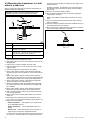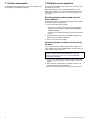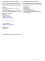
1
Do w n Vis io n T M
T h r u -H u ll
Tr a n s d u c e r s
CPT -70 / CPT -80 /
CPT -110 / CPT -120
Installation instructions
English
Date: 10-2013
Document number: 87201-1-EN
© 2013 Raymarine UK Limited
Trademark and patents notice
Autohelm, hsb2, RayTech Navigator, Sail Pilot, SeaTalk, SeaTalkNG, SeaTalkHS and Sportpilot are registered trademarks of
Raymarine UK Limited. RayTalk, Seahawk, Smartpilot, Pathfinder and Raymarine are registered trademarks of Raymarine
Holdings Limited.
FLIR is a registered trademark of FLIR Systems, Inc. and/or its subsidiaries.
All other trademarks, trade names, or company names referenced herein are used for identification only and are the property
of their respective owners.
This product is protected by patents, design patents, patents pending, or design patents pending.
Fair Use Statement
You may print no more than three copies of this manual for your own use. You may not make any further copies or distribute or use
the manual in any other way including without limitation exploiting the manual commercially or giving or selling copies to third parties.
Software updates
Check the website www.raymarine.com for the latest software releases for your product.
Product handbooks
The latest versions of all English and translated handbooks are available to download in PDF format from the website www.raymarine.com.
Please check the website to ensure you have the latest handbooks.
Copyright ©2013 Raymarine UK Ltd. All rights reserved.
ENGLISH
Document number: 87201-1
Date: 10-2013
Contents
Chapter 1 Important information........................ 7
9.2 Viewing product information .................................. 38
Certified Installation ................................................... 7
Transducer cleaning .................................................. 7
Chapter 10 Technical specification.................... 39
Water ingress ............................................................ 7
Disclaimer ................................................................. 7
Declaration of conformity............................................ 7
10.1 Technical specification ........................................ 40
Chapter 11 Spares and accessories .................. 41
11.1 Spares and accessories...................................... 42
Warranty registration.................................................. 7
Product disposal ........................................................ 8
IMO and SOLAS........................................................ 8
Technical accuracy .................................................... 8
Chapter 2 Document and product
information........................................................... 9
2.1 Document information .......................................... 10
2.2 CHIRP Sonar overview......................................... 11
2.3 CHIRP DownVisionTM overview............................. 11
Chapter 3 Planning the installation ................... 13
3.1 Installation checklist ............................................. 14
3.2 Parts supplied...................................................... 14
3.3 Required additional components ........................... 15
3.4 Compatible DownVisionTM products....................... 15
3.5 Tools required ...................................................... 16
3.6 Warnings and cautions ......................................... 16
3.7 Location requirements .......................................... 17
3.8 Transducer dimensions ........................................ 18
Chapter 4 Cables and connections.................... 19
4.1 General cabling guidance ..................................... 20
4.2 Cable routing ....................................................... 20
4.3 Connections overview .......................................... 21
4.4 Transducer cable connection ................................ 21
Chapter 5 Pre-installation test............................ 23
5.1 Testing the transducer .......................................... 24
Chapter 6 Mounting............................................. 25
6.1 Dead rise angle.................................................... 26
6.2 Mounting the transducer in a hull with a dead
rise ........................................................................... 27
6.3 Mounting the transducer in a hull without a dead
rise ........................................................................... 28
6.4 Cored fiberglass hull mounting .............................. 29
Chapter 7 System checks and
troubleshooting ................................................... 31
7.1 Further information............................................... 32
7.2 Multiple sonar operation ....................................... 32
7.3 Troubleshooting ................................................... 33
Chapter 8 Maintenance ....................................... 35
8.1 Routine checks .................................................... 36
8.2 Unit cleaning instructions ...................................... 36
Chapter 9 Technical support .............................. 37
9.1 Raymarine customer support ................................ 38
5
6
CPT-70 / CPT-80 / CPT-110 / CPT-120
Chapter 1: Important information
Certified Installation
Raymarine recommends certified installation by a Raymarine
approved installer. A certified installation qualifies for enhanced
product warranty benefits. Contact your Raymarine dealer for
further details, and refer to the separate warranty document
packed with your product.
Warning: Product installation and
operation
This product must be installed and operated in
accordance with the instructions provided. Failure
to do so could result in personal injury, damage to
your vessel and/or poor product performance.
Transducer cleaning
Growth can collect on the bottom of the transducer, this can
reduce performance. To prevent the build up of sea growth, coat
the transducer with a thin layer of water based antifouling paint,
available from your local marine dealer. Reapply paint every 6
months or at the beginning of each boating season. Certain
smart transducers have restrictions on where antifouling paint is
applied. Please consult your dealer.
Note: Transducers with a temperature sensor may not work
properly if painted.
Note: Never use ketone based paint. Ketones can attack
many plastics possibly damaging the sensor.
Note: Never use spray paint on your transducer. Spraying
incorporates tiny air bubbles, and a marine transducer cannot
transmit properly through air.
To prevent corrosion, NEVER install a transducer
with a bronze housing on a vessel with a metal hull.
Use a soft cloth and mild household detergent to clean the
transducer. If the fouling is severe, remove the growth with a
green scotch briteTM pad. Be careful to avoid scratching the
transducers face.
Warning: High voltages
If your transducer has a paddlewheel you can wet sand with
fine grade wet/dry paper.
Warning: Corrosion
This product contains high voltages. Do NOT
remove any covers or otherwise attempt to access
internal components, unless specifically instructed
in this document.
Warning: Positive ground systems
Do not connect this unit to a system which has
positive grounding.
Note: Harsh cleaning solvents such as acetone may damage
the transducer.
Water ingress
Water ingress disclaimer
The waterproof rating capacity of this product meets the stated
IPX standard referred to in the product’s Technical Specification.
Warning: Switch off power supply
Ensure the vessel’s power supply is switched OFF
before starting to install this product. Do NOT
connect or disconnect equipment with the power
switched on, unless instructed in this document.
Warning: Transducer operation
Only test and operate the transducer in the water.
Do NOT operate out of water as overheating may
occur.
Disclaimer
Raymarine does not warrant that this product is error-free or that
it is compatible with products manufactured by any person or
entity other than Raymarine.
Raymarine is not responsible for damages or injuries caused by
your use or inability to use the product, by the interaction of the
product with products manufactured by others, or by errors in
information utilized by the product supplied by third parties.
Caution: Power supply protection
Declaration of conformity
When installing this product ensure the power
source is adequately protected by means of a
suitably-rated fuse or automatic circuit breaker.
Raymarine UK Ltd. declares that this product is compliant with
the essential requirements of EMC directive 2004/108/EC.
Caution: Do not cut transducer
cables
• Cutting the transducer cable severely reduces
sonar performance. If the cable is cut, it must be
replaced, it cannot be repaired.
• Cutting the transducer cable will void the
warranty and invalidate the European CE mark.
Caution: Service and maintenance
This product contains no user serviceable
components. Please refer all maintenance
and repair to authorized Raymarine dealers.
Unauthorized repair may affect your warranty.
Important information
The original Declaration of Conformity certificate may be viewed
on the relevant product page at www.raymarine.com.
Warranty registration
To register your Raymarine product ownership, please visit
www.raymarine.com and register online.
It is important that you register your product to receive full
warranty benefits. Your unit package includes a bar code label
indicating the serial number of the unit. You will need this serial
number when registering your product online. You should retain
the label for future reference.
7
Product disposal
Dispose of this product in accordance with the WEEE Directive.
The Waste Electrical and Electronic Equipment (WEEE)
Directive requires the recycling of waste electrical and electronic
equipment. Whilst the WEEE Directive does not apply to some
Raymarine products, we support its policy and ask you to be
aware of how to dispose of this product.
IMO and SOLAS
The equipment described within this document is intended for
use on leisure marine boats and workboats not covered by
International Maritime Organization (IMO) and Safety of Life at
Sea (SOLAS) Carriage Regulations.
Technical accuracy
To the best of our knowledge, the information in this document
was correct at the time it was produced. However, Raymarine
cannot accept liability for any inaccuracies or omissions it
may contain. In addition, our policy of continuous product
improvement may change specifications without notice. As a
result, Raymarine cannot accept liability for any differences
between the product and this document. Please check the
Raymarine website (www.raymarine.com) to ensure you have
the most up-to-date version(s) of the documentation for your
product.
8
CPT-70 / CPT-80 / CPT-110 / CPT-120
Chapter 2: Document and product information
Chapter contents
•
2.1 Document information on page 10
•
2.2 CHIRP Sonar overview on page 11
•
2.3 CHIRP DownVisionTM overview on page 11
Document and product information
9
2.1 Document information
Further information
This document contains important information related to the
installation of your Raymarine product.
The document includes information to help you:
For detailed operating instructions, refer to the handbook that
accompanies your multifunction display.
Sonar module installation instructions
• plan your installation and ensure you have all the necessary
equipment;
• install and connect your product as part of a wider system of
connected marine electronics;
This document includes installation instructions for the
transducer only. For installation instructions for connecting
a sonar module, please refer to the documentation that
accompanies the sonar module.
• troubleshoot problems and obtain technical support if required.
This and other Raymarine product documents are available to
download in PDF format from www.raymarine.com.
DownVisionTM thru-hull transducers
The following DownVision thru-hull transducers are available
Part
number
Description
Mounting
Type
Construction
A80278
CPT-70
Dragonfly
DownVision
transducer
Throughhull
Plastic
A80279
CPT-80
Dragonfly
DownVision
transducer
Throughhull
Bronze
A80277
CPT-110
DownVision
transducer
Throughhull
Plastic
A80271
CPT-120
DownVision
transducer
Throughhull
Bronze
• CPT-80 and CPT-120 (Bronze) — bronze transducers
are recommended for fiberglass and wooden hulls. Not
recommended for use in a metal hull.
• CPT-70 and CPT-110 (Plastic) — plastic transducers are
recommended for fiberglass and metal hulls only. Not
recommended for use in a wooden hull.
Document illustrations
Your product may differ slightly from that shown in the
illustrations in this document, depending on product variant and
date of manufacture.
All images are provided for illustration purposes only.
Product documentation
The following documentation is applicable to your product:
Description
Part number
DownVision Thru-Hull transducer Installation
instructions
Installation of a CPT–70 / CPT–80 / CPT–110 /
CPT–120 transducer and connection to a sonar module
or multifunction display.
87201 / 88025
a Series, c Series, e Series Installation and operation
instructions
Details the operation of the fishfinder application
(including DownVision operation) for a Series, c Series,
e Series multifunction displays.
81337
Dragonfly Installation and operation instructions
Details the operation of the Sonar and DownVision
applications for Dragonfly multifunction displays.
81345
10
CPT-70 / CPT-80 / CPT-110 / CPT-120
2.2 CHIRP Sonar overview
2.3 CHIRP DownVisionTM overview
Sonar interprets signals from the transducer and builds up a
detailed underwater view. The transducer sends pulses of
sound waves into the water and measures the time it takes for
the sound wave to travel to the bottom and back. The returning
echoes are affected by bottom structure and by any other objects
in their path, for example reefs, wrecks, shoals or fish.
DownVisionTM interprets signals from the transducer and builds
up a detailed underwater view. The transducer sends pulses of
sound waves into the water and measures the time it takes for
the sound wave to travel to the bottom and back. The returning
echoes are affected by bottom structure and by any other objects
in their path, for example reefs, wrecks, shoals or fish.
Sonar produces a 25° conical shaped beam, the coverage of the
conical beam is the water column directly beneath the vessel.
DownVisionTM produces a wide–angle side-to-side beam and a
thin fore-to-aft beam. The coverage of the DownVisionTM beam
is a water column directly beneath and to the sides of the vessel.
Conical beam
DownVision beam
D12777-2
D12784-2
Sonar is effective at a range of speeds. In deeper waters the
CHIRP bandwidth is automatically optimized to improve bottom
lock and the detection of moving objects (e.g. fish) in the wider
water column.
CHIRP sonar screen example
DownVisionTM is effective at lower vessel speeds. In deeper
waters the CHIRP bandwidth is automatically optimized to
improve bottom lock and the detection of moving objects (e.g.
fish) in the wider water column.
The wide, thin beam produces clear target returns. The use of
CHIRP processing and a higher operating frequency provide
a more detailed image, making it easier to identify bottom
structures around which fish may reside.
CHIRP DownVisionTM screen example
Document and product information
11
12
CPT-70 / CPT-80 / CPT-110 / CPT-120
Chapter 3: Planning the installation
Chapter contents
•
3.1 Installation checklist on page 14
•
3.2 Parts supplied on page 14
•
3.3 Required additional components on page 15
•
3.4 Compatible DownVisionTM products on page 15
•
3.5 Tools required on page 16
•
3.6 Warnings and cautions on page 16
•
3.7 Location requirements on page 17
•
3.8 Transducer dimensions on page 18
Planning the installation
13
3.1 Installation checklist
3.2 Parts supplied
Installation includes the following activities:
The following parts are supplied with your product.
Installation Task
1
Plan your system.
2
Obtain all required equipment and tools.
3
Site all equipment.
4
Route all cables.
5
Drill cable and mounting holes.
6
Make all connections into equipment.
7
Secure all equipment in place.
8
Power on and test the system.
1
2
3
4
Schematic diagram
A schematic diagram is an essential part of planning any
installation. It is also useful for any future additions or
maintenance of the system. The diagram should include:
D12966-1
1
Thru-hull transducer
2
Dead rise block
3
Securing nut
4
Document pack
• Location of all components.
• Connectors, cable types, routes and lengths.
14
CPT-70 / CPT-80 / CPT-110 / CPT-120
3.3 Required additional components
This product forms part of a system of electronics and requires
the following additional components for full operation.
• Compatible DownVisionTM Sonar Module or DownVisionTM
variant multifunction display. Refer to 3.4 Compatible
DownVisionTM products, for a list of compatible products.
• Transducer extension cables. Refer to Chapter 4 Cables and
connections, for suitable cables.
3.4 Compatible DownVisionTM
products
The transducer can be connected directly to the following
DownVisionTM sonar modules and multifunction displays.
CPT-60 / CPT-70 / CPT-80
0
Description
Part number
Dragonfly
E70226
00
CPT-100 / CPT-110 / CPT-120
Planning the installation
Description
Part number
CP100
E70204
a68 / a68 Wi-Fi
E70206 / E70207
a78 / a78 Wi-Fi
E70208 / E70209
15
3.5 Tools required
3.6 Warnings and cautions
The following tools are required to install the transducer.
1
Important: Before proceeding, ensure that you have read
and understood the warnings and cautions provided in the
Chapter 1 Important information section of this document.
2
3
4
5
6
7
D12951-1
1
Angle finder
2
File
3
*Marine grade adhesive sealant (suitable for submerged
applications)
4
Drill bit (for drilling the pilot hole)
5
Adjustable spanner (suitable size for the transducer nut)
6
Band saw (for cutting the Dead rise block)
7
32 mm (1 1/4 in) hole cutter
Important:
*It is the installers responsibility to ensure correct installation.
Before installing the transducer please check the sealant
manufacturer’s guidelines to ensure it is suitable for use in
the intended environment and with the materials used in the
transducer and your vessel’s hull.
Raymarine accepts no liability for damage caused due to the
use of unsuitable materials.
16
CPT-70 / CPT-80 / CPT-110 / CPT-120
3.7 Location requirements
1
The guidelines below should be followed when selecting a
location for your transducer.
For best performance the transducer should be installed in a
location with the least turbulence and aeration.
2
Important: Do NOT install the transducer in-line with trailer
rollers, your vessel’s engine intake or discharge openings.
4
5
• The transducer should be installed as close to the centerline
of the vessel as possible.
3
D12953-1
1
2
4
3
5
6
D12952-1
1
Planing hull
Outboard or I/O — mount forward and to the side
of the propeller(s)
2
Planing hull
Inboard — mount forward of the propeller(s) and
shaft(s)
3
Planing hull
Stepped hull — mount on the first step as far aft
as possible
4
Displacement hull
Displacement hull — mount approximately 1/3 of
the way along the length of the hull, measured along
the waterline
5
Keel
sailboat
Fin keel — mount forward of the keel, ensuring that
the keel will not obstruct the transducers wide beam
width
6
Keel
sailboat
Full keel — mount away from the keel at a location
with minimum dead rise, ensuring that the keel will
not obstruct the transducers wide beam width
1
Vessel hull
2
Side view of transducer
3
Bottom view of transducer
4
Direction of bow
5
Direction of stern
• The transducer should be installed in a location where there
is sufficient clearance inside the hull to fit the nut and have at
least 100 mm (4 in) of headroom to allow for withdrawal.
• The transducer should be installed so that the bottom face of
the transducer is pointing straight down.
• The transducer should be installed away from any protrusions
such as transducers, steps, ribs, strakes, or rows of rivets.
3
1
2
4
D12636-1
1
Step
2
Rib
3
Row of rivets
4
Strake
• The transducer must be installed in the correct orientation.
Planning the installation
17
3.8 Transducer dimensions
The transducer’s dimensions are shown below.
CPT-70 and CPT-110 (Plastic)
M30 x 3.5
75.5 mm
(2.97 in)
30 mm
(1.18 in)
25 mm
(0.98 in)
210.8 mm (8.3 in)
52 mm (2 in)
D12965-2
CPT-80 and CPT-120 (Bronze)
M32 x 2
105.5 mm
(4.2 in)
26.3 mm
(1 in)
210.8 mm (8.3 in)
52 mm (2 in)
D12954-1
18
CPT-70 / CPT-80 / CPT-110 / CPT-120
Chapter 4: Cables and connections
Chapter contents
•
4.1 General cabling guidance on page 20
•
4.2 Cable routing on page 20
•
4.3 Connections overview on page 21
•
4.4 Transducer cable connection on page 21
Cables and connections
19
4.1 General cabling guidance
4.2 Cable routing
Cable types and length
Cable routing requirements for the transducer cable.
It is important to use cables of the appropriate type and length
• Unless otherwise stated use only standard cables of the
correct type, supplied by Raymarine.
• Ensure that any non-Raymarine cables are of the correct
quality and gauge. For example, longer power cable runs may
require larger wire gauges to minimize voltage drop along the
run.
• Check that the cable is long enough to reach the equipment
that it will be connected to. Refer to the manual that
accompanied your sonar module for details of transducer
extension cables.
• Use grommets in any pass through holes to prevent damage
to the transducer cable.
• To prevent interference, separate the transducer cable from
any other electrical cables.
Routing cables
• Secure the cable at regular intervals using cable clips (not
supplied).
Cables must be routed correctly, to maximize performance and
prolong cable life.
• Any excess cable should be coiled up at a convenient location.
• Do NOT bend cables excessively. Wherever possible, ensure
a minimum bend diameter of 200 mm (8 in) / minimum bend
radius of 100 mm (4 in).
200 mm (8 in)
100 mm (4 in)
• Protect all cables from physical damage and exposure to heat.
Use trunking or conduit where possible. Do NOT run cables
through bilges or doorways, or close to moving or hot objects.
• Secure cables in place using tie-wraps or lacing twine. Coil
any extra cable and tie it out of the way.
• Where a cable passes through an exposed bulkhead or
deckhead, use a suitable watertight feed-through.
• Do NOT run cables near to engines or fluorescent lights.
Always route data cables as far away as possible from:
• other equipment and cables,
• high current carrying ac and dc power lines,
• antennae.
Strain relief
Ensure adequate strain relief is provided. Protect connectors
from strain and ensure they will not pull out under extreme sea
conditions.
Cable shielding
Ensure that all data cables are properly shielded that the
cable shielding is intact (e.g. hasn’t been scraped off by being
squeezed through a tight area).
20
CPT-70 / CPT-80 / CPT-110 / CPT-120
4.3 Connections overview
4.4 Transducer cable connection
Use the following information to help you identify the connections
on your product.
The transducer can be connected directly to a DownVision sonar
module or a DownVision variant multifunction display.
Connector
Connector type
Connects to:
CPT-60 / CPT-70 /
CPT–80 Transducer
and display power
Dragonfly display
CPT-100 /
CPT-110 / CPT-120
Transducer
Follow the Cables and Connections chapter of the manual
that accompanied your sonar module or DownVision variant
multifunction display to make the appropriate connections.
Making connections
Sonar module or
compatible multifunction
display.
Follow the steps below to connect the cable(s) to your product.
1. Ensure that the vessel's power supply is switched off.
2. Ensure that the device being connected to the unit has
been installed in accordance with the installation instructions
supplied with that device.
3. Ensuring correct orientation, push the cable connector fully
onto the corresponding connector on the unit.
4. Turn the locking collar clockwise to secure the cable.
Transducer cable extension
For some installations it may be necessary to extend the
transducer cable.
• Refer to Chapter 11 Spares and accessories for a list of
suitable transducer extension cables.
• Raymarine recommends a maximum of one cable extension
for any single transducer cable.
• For best performance, keep all cable lengths to a minimum.
Cables and connections
21
22
CPT-70 / CPT-80 / CPT-110 / CPT-120
Chapter 5: Pre-installation test
Chapter contents
•
5.1 Testing the transducer on page 24
Pre-installation test
23
5.1 Testing the transducer
Transducer operation should be checked before installation.
1. Connect the transducer to the sonar module’s transducer
connection.
2. Fully submerge the transducer in water.
3. Power up the sonar module and the multifunction display
connected to it.
4. Open a Fishfinder application page on your multifunction
display.
5. Check that accurate depth and temperature readings are
displayed in the Fishfinder application.
6. If you experience difficulties obtaining readings then contact
Raymarine Technical Support.
Note: The transducer may be connected directly to a
multifunction display that has a built in DownVision sonar
module.
Warning: Transducer operation
Only test and operate the transducer in the water.
Do NOT operate out of water as overheating may
occur.
24
CPT-70 / CPT-80 / CPT-110 / CPT-120
Chapter 6: Mounting
Chapter contents
•
6.1 Dead rise angle on page 26
•
6.2 Mounting the transducer in a hull with a dead rise on page 27
•
6.3 Mounting the transducer in a hull without a dead rise on page 28
•
6.4 Cored fiberglass hull mounting on page 29
Mounting
25
6.1 Dead rise angle
The dead rise angle is the angle of the vessels hull from the
centerline.
4
Slope of hull
5
Dead rise angle 25 degrees maximum
1. Calculate the dead rise angle.
1
2.
3.
4
4.
3
2
D12955-1
1
Waterline
2
Centerline
3
Dead Rise Angle
4
Parallel with waterline
5.
The dead rise angle should be measured on the outside of
the hull from the location that the transducer is to be mounted
using an angle finder or similar device.
Adjust the band saw table to the measured angle of your
dead rise
Position the dead rise block on the band saw table so that
the top of the block is against the band saw’s cutting guide.
Ensure that the block is correctly orientated, the arrow on top
of the Dead rise block should be pointing towards the bow
of the vessel.
Position the Dead rise block and cutting guide so that the cut
will create 2 equally sized parts.
Note: You must leave a minimum of 4 mm (0.16 in) gap from
the bottom of the Dead rise block as shown in the diagram
above.
The dead rise angle should be measured on the outside of the
hull using an angle finder or similar device.
6. Recheck steps 1 to 5.
7. Cut the block.
Example dead rise angles
1
0
o
33
24
o
2
4
3
o
D12956-1
• Bronze transducer — The dead rise block is not required on
hulls with a flat bottom. For hulls with a dead rise angle the
block should always be used.
• Plastic transducer — On a hull with a flat bottom the Dead
rise block does not require cutting and should be used inside
the hull. For hulls with a dead rise angle the block should
always be used.
Cutting the Dead rise block
Unless the vessel hull has a flat bottom, the Dead rise block
must be cut to the shape of the hull, do NOT over tighten the
nut in an attempt to close any gaps between the block and hull
as this may damage the transducer and Dead rise block. The
Dead rise block is not suitable for vessels with a dead rise angle
greater than 25 degrees.
D12958-1
Retain the top half of the block as this will provide a level
surface inside the hull to tighten the nut against.
8. Check the bottom half of the dead rise block against the hull
to ensure a good fit.
Ensure that the block runs parallel to the centerline of the
vessel.
9. If there are gaps between the block and hull then use an
appropriate file to shape the block until a precision fit is
achieved.
Removing dead rise block locators
When installing the plastic transducer on a vessel with no dead
rise you must remove the locators from the bottom of the dead
rise block.
1
1
5
2
2
D12959-1
2
3
4
D12957-1
1
Dead Rise block (Front of block facing forward)
2
Parallel to waterline
3
4 mm (0.16 in) gap minimum
26
1
Dead rise block
2
locators (for locating on the transducer)
1. Remove the dead rise block from the transducer.
2. Using a suitable saw, cut the locators from the bottom of the
block.
The block is now ready to be used inside the hull as described in
the Mounting the transducer in a hull without a dead rise section.
CPT-70 / CPT-80 / CPT-110 / CPT-120
6.2 Mounting the transducer in a hull
with a dead rise
When mounting the transducer in a hull that has a dead rise
angle the transducer should be mounted following the steps
below.
Important: Do NOT remove the label attached to the
transducer cable as it contains important information.
1
2
3
4
16. With a person inside the vessel, place the top half of the
dead rise block over the threaded tube.
17. Apply a thick bead of marine grade adhesive sealant all
around the edge of the top face of the top half of the cut dead
rise block, where it will meet the nut.
18. Apply a thick bead of marine grade adhesive sealant to the
bottom of the nut.
19. Ensuring that the dead rise block and transducer do not
move, secure the transducer assembly by tightening the nut.
20. Tighten the nut as follows:
• Plastic transducer — Hand tighten, plus a quarter turn
of the adjustable spanner.
• Bronze transducer — Use an adjustable spanner to
tighten.
5
4
4
• Wooden hull — Allow the wooden hull to swell prior to
tightening the nut using the adjustable spanner.
6
In order to prevent leaks and transducer movement when hit
by waves etc., ensure that the nut is adequately tightened.
You should see the sealant protruding from the edges of the
applied surfaces.
7
4
8
4
4
D12960-1
1
Transducer cable
2
Vessel hull
3
Nut
4
Marine grade adhesive sealant — suitable for submerged
applications (not supplied)
5
Top half of Dead rise block
6
Bottom half of Dead rise block
7
Threaded Tube
8
Transducer
1. Align the bottom half of the Dead rise block so that it is
parallel to the centerline (keel) of the vessel.
2. Using a permanent marker, draw around the outside edge of
the block and the internal hole for the threaded tube.
3. Remove the block from the hull.
4. Drill a pilot hole in the center of the location marked out on
the hull for the threaded tube.
5. Drill the hole out using a suitable size hole cutter.
6. Using sandpaper and / or a file ensure there are no rough
edges or burrs.
7. Ensure all surfaces are clean and free from debris.
8. Apply a thick bead of marine grade adhesive sealant all
around the edge of the top face of the transducer and the
bottom face of the Dead rise block.
9. Apply a thick bead of marine grade adhesive sealant up
each side of the threaded tube, ensuring that the sealant will
protrude approximately 6 mm above the final tightened nut.
10. Feed the transducer cable through the dead rise block’s
threaded tube hole.
11. Push the dead rise block down onto the transducer ensuring
that the locators on the block line up with the locator holes
on the transducer.
12. Apply a thick bead of marine grade adhesive sealant all
around the edge of the top face of the bottom half of the cut
dead rise block, where it will meet the hull.
13. Apply a thick bead of marine grade adhesive sealant all
around the edges of the hole in the hull.
14. Guide the transducer cable and threaded tube up through
the vessel hull and ensure the transducer is lined up with
the markings made in step 2.
15. Apply a thick bead of marine grade adhesive sealant all
around the edge of the bottom face of the top half of the cut
dead rise block, where it will meet the hull.
Mounting
Do NOT overtighten. Overtightening can cause damage to
the transducer and hull which may result in water leaking
into the hull.
21. Remove any excess adhesive sealant.
22. Ensure that the sealant has fully cured before putting the
vessel back in the water.
Refer to the sealant manufacturers instructions for curing
times.
23. Once the vessel has been put back in the water check for
leaks immediately.
24. Check for leaks at regular intervals after installation until you
are satisfied that there are no leaks.
25. Ensure checking for leaks around the transducer is added to
your routine vessel maintenance schedule.
6 mm
1
2
3
5
4
D12961-1
1
Nut
2
Top half of dead rise block
3
Bottom half of dead rise block
4
transducer
5
Marine grade adhesive sealant — suitable for submerged
applications (not supplied)
27
6.3 Mounting the transducer in a hull
without a dead rise
When mounting the transducer in a hull with a flat bottom (no
dead rise) follow the steps below.
Important: Do NOT remove the label attached to the
transducer cable as it contains important information.
2
1
Do NOT overtighten. Overtightening can cause damage to
the transducer and hull which may result in water leaking
into the hull.
15. Remove any excess adhesive sealant.
16. Ensure that the sealant has fully cured before putting the
vessel back in the water.
Refer to the sealant manufacturers instructions for curing
times.
17. Once the vessel has been put back in the water check for
leaks immediately.
18. Check for leaks at regular intervals after installation until you
are satisfied that there are no leaks.
19. Ensure checking for leaks around the transducer is added to
your routine vessel maintenance schedule.
3
4
3
3
3
You should see the sealant protruding from the edges of the
applied surfaces.
3
3
5
D12962-1
1
Hull
2
Nut
3
Marine grade adhesive sealant — suitable for submerged
applications (not supplied)
4
Dead rise block — The dead rise block or suitable spacer
should be used between the nut and the hull
5
transducer
D12963-2
1. Ensure an appropriate location for the transducer has been
selected following the guidelines provide.
2. Drill a pilot hole in the center of the selected location for the
threaded tube.
3. Drill the hole out using a suitable size hole cutter.
4. Using sandpaper and / or a file ensure there are no rough
edges or burrs.
5. Ensure all surfaces are clean and free from debris.
6. Apply a thick bead of marine grade adhesive sealant all
around the top face of the transducer, where it will meet the
hull.
7. Apply a thick bead of marine grade adhesive sealant up
each side of the threaded tube, ensuring that the sealant will
protrude approximately 6 mm above the final tightened nut.
8. Apply a thick bead of marine grade adhesive sealant all
around the edges of the hole in the hull.
9. Guide the transducer cable and threaded tube up through
the vessel’s hull and ensure the transducer is parallel with
the centerline.
10. Apply a thick bead of marine grade adhesive sealant all
around the top and bottom faces of the dead rise block.
11. With a person inside the vessel, place the dead rise block
over the threaded tube.
12. Apply a thick bead of marine grade sealant to the bottom
of the nut.
13. Ensuring that the dead rise block and transducer do not
move, secure the transducer assembly by tightening the nut.
14. Tighten the nut as follows:
• Plastic transducer — Hand tighten, plus a quarter turn
of the adjustable spanner.
• Bronze transducer — Use an adjustable spanner to
tighten.
• Wooden hull — Allow the wooden hull to swell prior to
tightening the nut using the adjustable spanner.
In order to prevent leaks and transducer movement when hit
by waves etc., ensure that the nut is adequately tightened.
28
CPT-70 / CPT-80 / CPT-110 / CPT-120
6.4 Cored fiberglass hull mounting
If installing in a cored fiberglass hull the transducer should be
mounted in a non-cored section.
Before installing in a cored section of the hull the area around
the hole must be adequately strengthened to ensure it is not
damaged when tightening the transducer.
Important: Installation in a cored hull should only be carried
out by a competent marine installer.
Mounting
29
30
CPT-70 / CPT-80 / CPT-110 / CPT-120
Chapter 7: System checks and troubleshooting
Chapter contents
•
7.1 Further information on page 32
•
7.2 Multiple sonar operation on page 32
•
7.3 Troubleshooting on page 33
System checks and troubleshooting
31
7.1 Further information
7.2 Multiple sonar operation
For detailed operating instructions, refer to the handbook that
accompanies your multifunction display.
For systems with multiple sonar modules, only one sonar may
operate at any one time.
Before attempting to use the fishfinder application on your
multifunction display, use one of the methods described in this
document to ensure that only one sonar module is active on
your system.
Switching between internal and external
sonar modules
If you want to switch your active sonar module between internal
and external follow the steps below.
1. Power off the active sonar module.
• Internal sonar module is turned off from the Fishfinder
application menu: Menu > Set-up > Sounder Set-up >
Internal Sounder.
• External sonar modules should be turned off at the power
supply.
2. Wait for the No Sounder Source Available message to be
displayed in the Fishfinder application.
3. Power on the new sonar module.
Switching between multiple external sonar
modules
If your system includes multiple external sonar modules you
must complete the procedure detailed below to ensure only one
sonar module is active at a time.
Note: If your multifunction display has an internal sonar
module, complete the procedure detailed in Switching
between internal and external sonar modules BEFORE
attempting the following:
1. Power off ALL external sonar modules, either at the power
supply or by disconnecting the power cable from the sonar
module.
2. Wait for the No Sounder Source Available message to be
displayed in the Fishfinder application.
3. Power on the external sonar module that you want to use.
32
CPT-70 / CPT-80 / CPT-110 / CPT-120
7.3 Troubleshooting
The troubleshooting information provides possible causes and
corrective action required for common problems associated with
marine electronics installations.
All Raymarine products are, prior to packing and shipping,
subjected to comprehensive test and quality assurance
programs. However, if you experience problems with the
operation of your product this section will help you to diagnose
and correct problems in order to restore normal operation.
If after referring to this section you are still having problems
with your unit, please contact Raymarine Technical Support for
further advice.
System checks and troubleshooting
33
Sonar troubleshooting
Problems with the sonar and their possible causes and solutions are described here.
Problem
Possible causes
Possible solutions
Sonar data not available on
multifunction display.
Unit power supply fault.
Check the unit power supply and cables.
Other unit fault.
Refer to the instructions supplied with the unit.
SeaTalkhs / RayNet network problem.
Check that the unit is correctly connected to a Raymarine network
switch. If a crossover coupler or other coupler cable / adapter is used,
check all connections (as applicable).
Check the status of the Raymarine network switch (if applicable).
Check that SeaTalkhs/ RayNet cables are free from damage.
Problematic depth readings or sonar
image.
Software mismatch between equipment
may prevent communication.
Contact Raymarine technical support.
Gain or Frequency settings may be
inappropriate for present conditions.
Check the sonar presets, gain and frequency settings.
Unit power supply fault.
Check the voltage from the power supply, if this is too low it can affect
the transmitting power of the unit.
Unit cable fault.
Ensure that the power, transducer and all other cables to the unit are
properly connected and free from damage.
Transducer fault.
Check that the transducer is mounted correctly and is clean.
If you have a transom mount transducer, check that the transducer
hasn't kicked-up due to hitting an object.
Other unit fault.
Refer to the instructions supplied with the unit.
Vessel stationary.
Fish arches are not displayed if the vessel is stationary; fish will appear
on the display as straight lines.
High vessel speed
Turbulence around the transducer may be confusing the unit.
Scroll speed set to zero
Adjust the scroll speed.
Resetting the sonar module
You can use the reset function on a compatible Raymarine
multifunction display to restore the sonar module to its factory
default settings.
In
1.
2.
3.
4.
5.
the fishfinder application:
Select Menu.
Select Set-up.
Select Sounder Set-up.
Select Sonar Reset.
Select Yes to confirm or No to abort the operation, as
appropriate.
The unit will now be reset to factory default settings.
34
CPT-70 / CPT-80 / CPT-110 / CPT-120
Chapter 8: Maintenance
Chapter contents
•
8.1 Routine checks on page 36
•
8.2 Unit cleaning instructions on page 36
Maintenance
35
8.1 Routine checks
8.2 Unit cleaning instructions
The following periodic checks should be made:
The unit does not require regular cleaning. However, if you find
it necessary to clean the unit, please follow the steps below:
1. Ensure power is switched off.
2. Wipe unit clean with a damp cloth.
3. If necessary, use a mild detergent solution to remove grease
marks.
• Examine cables for signs of damage, such as chafing, cuts or
nicks.
• Check that the cable connectors are firmly attached and that
their locking mechanisms are properly engaged.
Note: Cable checks should be carried out with the power
supply switched off.
Warning: High voltage
This product contains high voltage. Adjustments
require specialized service procedures and tools
only available to qualified service technicians.
There are no user serviceable parts or adjustments.
The operator should never remove the cover or
attempt to service the product.
Transducer care and cleaning
Growth can collect on the bottom of the transducer, this can
reduce performance. To prevent the build-up of sea growth, coat
the transducer with a thin layer of water-based antifouling paint,
available from your local marine dealer. Reapply paint every 6
months or at the beginning of each boating season. Certain
smart transducers have restrictions on where antifouling paint is
applied. Please consult your dealer.
Note: Transducers with a temperature sensor may not work
properly if painted.
Note: Never use ketone-based paint. Ketones can attack
many plastics, possibly damaging the sensor.
Note: Never use spray paint on your transducer. Spraying
incorporates tiny air bubbles, and a marine transducer cannot
transmit properly through air.
Use a soft cloth and mild household detergent to clean the
transducer. If the fouling is severe, remove the growth with
a tough cleaning pad, such as a green Scotch BriteTM pad
for example. Be careful to avoid scratching the face of the
transducer.
Note: Harsh cleaning solvents such as acetone WILL damage
the transducer.
36
CPT-70 / CPT-80 / CPT-110 / CPT-120
Chapter 9: Technical support
Chapter contents
•
9.1 Raymarine customer support on page 38
•
9.2 Viewing product information on page 38
Technical support
37
9.1 Raymarine customer support
9.2 Viewing product information
Raymarine provides a comprehensive customer support service.
You can contact customer support through the Raymarine
website, telephone and e-mail. If you are unable to resolve a
problem, please use any of these facilities to obtain additional
help.
You can view information about your unit from the Diagnostics
menu on a compatible multifunction display. This option displays
information such as product serial number and software version.
Web support
Please visit the customer support area of our website at:
www.raymarine.com
This contains Frequently Asked Questions, servicing information,
e-mail access to the Raymarine Technical Support Department
and details of worldwide Raymarine agents.
With the Homescreen displayed:
1. Select Set-up.
2. Select Maintenance.
3. Select Diagnostics.
4. Select the Select Device option.
A list of connected devices is displayed.
5. Select the product for which you want to view information.
Alternatively, select Show All Data to display information for
all connected products.
Telephone and e-mail support
In the USA:
• Tel: +1 603 324 7900
• Toll Free: +1 800 539 5539
• E-mail: [email protected]
In the UK, Europe, and the Middle East:
• Tel: +44 (0)13 2924 6777
• E-mail: [email protected]
In Southeast Asia and Australia:
• Tel: +61 (0)29479 4800
• E-mail: [email protected]
Product information
If you need to request service, please have the following
information to hand:
• Product name.
• Product identity.
• Serial number.
• Software application version.
• System diagrams.
You can obtain this product information using the menus within
your product.
38
CPT-70 / CPT-80 / CPT-110 / CPT-120
Chapter 10: Technical specification
Chapter contents
•
10.1 Technical specification on page 40
Technical specification
39
10.1 Technical specification
Physical specification
Dimensions
• Length: 210.8 mm (8.3 in)
• Height: 131.8 mm (5.2 in) Max
Cable length
10 m (32.8 ft)
Transducer environmental specification
Operating
temperature
0 ºC to + 40 ºC (32 ºF to 104 ºF)
Storage temperature
–20 ºC to + 70 ºC (23 ºF to 158 ºF)
Waterproof rating
• IPX6 and IPX7
Sonar / DownVision specification
Channels
2 x CHIRP (1 x sonar and 1 x DownVision)
Operating
frequencies
• Sonar — Centered 200 KHz
Beam coverage
• DownVision — Centered 350 KHz
• Sonar — 25° conical beam.
• DownVision — Wide (port / starboard) and thin
(fore / aft) fan beam.
Target separation
Achieved through CHIRP processing:
• Sonar — 32 mm (1.25 in).
• DownVision — 25 mm (1 in).
Depth
Typical depth performance of 189 m (600 ft). Applies
to both Sonar and DownVision channels.
Conformance specification
Conformance
• EN 60945:2002
• IEC 28846:1993
• EMC Directive 2004/108/EC
• Australia and New Zealand:
C-Tick, Compliance Level 2
40
CPT-70 / CPT-80 / CPT-110 / CPT-120
Chapter 11: Spares and accessories
Chapter contents
•
11.1 Spares and accessories on page 42
Spares and accessories
41
11.1 Spares and accessories
Spares
Description
Part number
Dead Rise (fairing) block (CPT-70 /
CPT-80 / CPT-110 / CPT-120)
R70258
Replacement Bronze securing nut
(CPT-80 / CPT-120)
R70260
Replacement Plastic securing nut
(CPT-70 / CPT-110)
R70259
Accessories
Description
Part number
4 m (13.1 ft.) Transducer extension
cable (CPT-110 / CPT-120)
A80273
4 m (13.1 ft.) Dragonfly transducer
extension cable (CPT-70 / CPT-80)
A80224
42
CPT-70 / CPT-80 / CPT-110 / CPT-120
www.ra ym a rin e .c o m