1
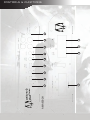
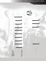
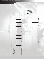
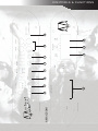
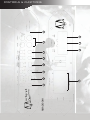
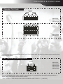
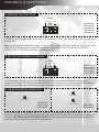
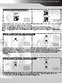
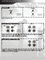
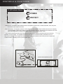
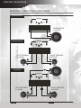
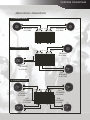
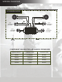
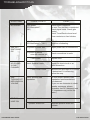
By
AMA12004H/AMA12004H
AMA6002H/AMA12002H/AMA24002H
OWNER’S MANUAL
FEATURES & SPECIFICATIONS
FEATURES
•
•
•
•
•
•
•
•
• Variable High Pass Filter: 50Hz - 750Hz
Class A/B MOSFET Power Amplifier
• Variable Low Pass Filter: 50Hz - 120Hz
2 Ohm stable
• Sub Sonic Control: 20Hz - 50Hz
MOSFET High Speed Switching Power Supply
• Bass Boost Control: 18dB
RCA (Low Level) Inputs
• Variable Bass Control remote: 0dB - 18dB
Bridgeable
• Phase Shift Switch: 0º - 180º
Input Sensitivity: 200mV - 8V
Optional Item: Bass Boost Control
4-Way Protection Circuitry: Thermal, Short Circuit, Overload, & DC Offset
RECOMMENDED FUSE SIZE
(AMA6002H: 20 x 1) (AMA12002H: 20 x 2) (AMA24002H: 30 x 2) (AMA12004H: 20 x 2) (AMA24004H: 30 x 2)
POWER OUTPUT
AMA6002H:
600 Watts Achievable Power
75 x 2 @ 4 Ohms RMS
150 x 2 @ 2 Ohms RMS
300 x 1 @ 4 Ohms RMS
AMA12002H:
1200 Watts Achievable Power
150 x 2 @ 4 Ohms RMS
300 x 2 @ 2 Ohms RMS
600 x 1 @ 4 Ohms RMS
AMA24002H:
AMA12004H:
1200 Watts Achievable Power
75 x 4 @ 4 Ohms RMS
150 x 4 @ 2 Ohms RMS
300 x 2 @ 4 Ohms RMS
2400 Watts Achievable Power
150 x 4 @ 4 Ohms RMS
300 x 4 @ 2 Ohms RMS
600 x 2 @ 4 Ohms RMS
AMA24004H:
2400 Watts Achievable Power
300 x 2 @ 4 Ohms RMS
600 x 2 @ 2 Ohms RMS
1200 x 1 @ 4 Ohms RMS
DIMENSIONS
AMA6002H (W x H x D):
8.95” x 8.48” x 2.64”
227.5 x 215.5 x 67mm
AMA12002H (W x H x D): 8.95” x 8.48” x 2.64”
227.5 x 215.5 x 67mm
AMA24002H (W x H x D): 11.57” x 8.48” x 2.64”
294 x 215.5 x 67mm
AMA12004H (W x H x D): 12.09” x 8.48” x 2.64”
307 x 215.5 x 67mm
AMA24004H (W x H x D): 12.09” x 8.48” x 2.64”
307 x 215.5 x 67mm
AMA6002H
1
7
6
8
14
9
11
3
5
4
2
10
16
CONTROLS & FUNCTIONS
AMA12002H
15
1
7
6
8
14
9
5
4
3
11
2
10
16
CONTROLS & FUNCTIONS
AMA24002H
15
1
7
6
8
14
9
5
4
3
11
2
10
16
CONTROLS & FUNCTIONS
AMA12004H
7
1
6
8
14
9
5
4
3
10
2
16
CONTROLS & FUNCTIONS
AMA24004H
7
1
6
8
14
9
5
4
3
10
2
16
CONTROLS & FUNCTIONS
CONTROLS & FUNCTIONS
1. Speaker Terminals
SPEAKER
Bridged
L
R
AMA6002H
AMA12002H
AMA24002H
CH1
CH2
CH3
Bridged
CH1
CH4
Bridged
CH2
CH3
CH4
AMA12004H
AMA24004H
These chrome plated connectors can accept from 16 to 8 gauge wire. Be careful to observe proper polarity when
connecting the cables
2. B - Terminal (Chassis ground)
POWER
GND
REM
BATT
AMA6002H
AMA12002H
AMA24002H
AMA12004H
AMA24004H
To avoid unwanted ignition noise caused by ground loops, it is essential that the amplifier be grounded to a
clean, bare, metal surface of the vehicles chassis.
Note: GROUND WIRE SHOULD NOT BE EXTENDED MORE THAN 3 FT. (1 METER)
CONTROLS & FUNCTIONS
3. Remote Turn-On Input
POWER
GND
REM
BATT
AMA6002H
AMA12002H
AMA24002H
AMA12004H
AMA24004H
To remote or power antenna output of car stereo. This amplifier is turned "ON" remotely when the vehicle's stereo
is turned "ON".
Note: IF YOUR RADIO DOES NOT HAVE +12 VOLT OUTPUT LEAD WHEN THE RADIO IS TURNED ON, THE
"REMOTE" TERMINAL ON THE AMPLIFIER CAN BE CONNECTED TO THE VEHICLE'S ACCESSORY
CIRCUIT THAT IS LIVE WHEN THE KEY (IGNITION) IS "ON".
4. B+ Terminal (Battery Positive)
POWER
GND
REM
BATT
AMA6002H
AMA12002H
AMA24002H
AMA12004H
AMA24004H
Due to the power requirements of the amplifier, this connection should be made directly to the positive (+)
terminal of the battery. For a safety measure, install an in-line fuse holder (not included) as close to the battery
positive (+) as possible with an apmere rating not to exceed the total value of fuses in the amp.
5. Input Sensitivity Adjustment
MIN
MIN
MAX
MIN
MAX
MAX
AMA6002H
AMA12002H
AMA24002H
AMA12004H
AMA24004H
This control adjusts the amplifier's sensitivity to match the signal strength coming from the source unit. Input
sensitivity is variable from 200 Millivolts to 8 volts. Clockwise increases sensitivity. Counterclockwise decreases
sensitivity. THE KNOB IS NOT A VOLUME CONTROL. A lower signal level will require increased sensitivity for
full power. A higher signal will require decreased sensitivity.
CONTROLS & FUNCTIONS
AMA6002H
AMA12002H
AMA24002H
AMA12004H
AMA24004H
AMA6002H
AMA12002H
AMA24002H
AMA12004H
AMA24004H
50 150
50 150
AMA6002H
AMA12002H
AMA24002H
50 150
AMA12004H
AMA24004H
CONTROLS & FUNCTIONS
AMA6002H
AMA12002H
AMA24002H
AMA12004H
AMA24004H
AMA6002H
AMA12002H
AMA24002H
AMA12004H
AMA24004H
CONTROLS & FUNCTIONS
12. Remote Bass Knob Port Fig 1
DVM REMOTE
Bass Boost Control (MIN / MAX) : Optional
14. Bass Boost Switch
BASS
BOOST
BASS
BOOST
ON
ON
OFF
OFF
AMA6002H
AMA12002H
AMA24002H
AMA12004H
AMA24004H
ON
Bass Boost Switch: ON and OFF
OFF
CONTROLS & FUNCTIONS
16. LED indicator (Status)
POWER
PROTECT
-PWR (Power) : This BLUE LED will illuminate when the amplifier is turned "ON". If it fails to illuminate, check the power
connections to the amplifier and fuses.
- PROT (Protection) : The amplifier protection circuitry will disable the amplifier if input overload, short circuit, or extremely
high temperature conditions are detected. When the protection mode is in operation, the LED indicator on the side
panel will be illuminated, indicating the amplifier has gone into a self-preservation mode.
If you observe that the protection LED is lit, please check the system carefully to determine what has caused the
protection circuit to engage. The amplifier shut down due to a thermal overload condition, please allow it to cool
down before restarting. If the amplifier shut down because of an input overload or short circuit, be sure to repair these
conditions before attempting to power up the amplifier again.
Fig 2.
LINE CODE
Optional Remote Bass Boost Control
MIN
MAX
PLANNING/MOUNTING YOUR SYSTEM
Planning Your System
Before beginning the installation, consider the following:
If you plan to expand your system by adding other components sometime in the
a.
future, ensure that adequate space is left, and cooling requirements are met.
If your radio/source is equipped with Pre-Amp outputs, it is possible to utilize
them to drive an Amplifier and connecting (Amplifier) to the 2 rear speakers.
Then, use the built-in power of your radio to drive the 2 front speakers.
NOTE:
DISTORTION LEVEL IS CONSIDERABLY LOWER FROM PRE-AMP (LOW LEVEL) OUTPUTS, THAN
SPEAKER (HIGH LEVEL) OUTPUTS.
b.
Are your components matched? The RMS power rating of your speakers must
be equal or greater than the Amplifier’s. They also must be 1-8 Ohms
impedance (this information is normally printed on the speaker magnet).
c.
Consider both the length of your leads, and routing when determining the mounting
location. Pre-Amp input Jacks require a length of high quality shielded male to male
RCA patch cord.
Mounting Your System
The mounting position of your Amplifier will have great effect on its ability to dissipate the heat generated
during normal operation. It has an ample heat sink for heat dissipation, and also is designed with a thermal
shut-down (for heat protection) circuit, having enough air directed over the cooling fins will improve heat dissipation dramatically. DO NOT enclose the amplifier in a small box or cover it so that air can not flow around
the fins. Temperatures in car trunks have been measured as high as (155˚F) in the summer time. Since the
thermal shut-down point for the Amplifier is (158˚F) it is easy to see that it must be mounted for maximum
cooling capability. To achieve the maximum advantage of convection air flow in an enclosed trunk, mount the
amplifier in a horizontal position. Cooling requirements are considerably relaxed when mounting inside the
passenger compartment since the driver will not allow temperatures to reach a critical point. Floor mounting
under the seat is usually satisfactory as long as there is at least 1 inch (2.54cm) above the Amplifier’s fins for
ventilation.
a.
Select a sutable location that is convenient for mounting, accessible for wiring and has
ample room for air circulation and cooling.
b.
Use the amplifier as a template to mark the mounting holes. Remove the amplifier and
drill holes. Use extreme caution. Inspect underneath the surfaces before drilling!
c.
Secure the Amplifier using the screws provided.
CAUTION:
Before connecting any wires to the amplifier, disconnect the ground lead from
the battery. Leave the ground lead disconnected until you are done wiring the
amplifier.
WIRING DIAGRAM
AMA6002H / AMA12002H / AMA24002H
MONO MODE
BRIDGED
L
R
SUBWOOFER
4~8 OHM
STEREO MODE
BRIDGED
L
R
RIGHT SPEAKER
2~8 OHM
LEFT SPEAKER
2~8 OHM
TRI MODE
BRIDGED
L
LEFT SPEAKER
4~8 OHM
: INDUC TOR LOW PASS FILTER
R
BRIDGED
4~8 OHM
RIGHT SPEAKER
4~8 OHM
: CAPAC ITOR HIGH PASS FILTER
WIRING DIAGRAM
AMA12004H / AMA24004H
2 CHANNEL MODE
BRIDGED
4~8 OHM
CH1
CH 2 CH 3
CH 4
BRIDGED
CH1
BRIDGED
CH 2
CH 3
BRIDGED
4~8 OHM
CH 4
3 CHANNEL MODE
CH1
CH 2 CH 3
CH 4
BRIDGED
CH1
SPEAKER
2~8 OHM
CH1
BRIDGED
CH 2
CH 3
BRIDGED
4~8 OHM
CH 4
CH2
SPEAKER
2~8 OHM
4 CHANNEL MODE
CH1
CH2
SPEAKER
2~8 OHM
CH 2 CH 3
BRIDGED
CH1
SPEAKER
2~8 OHM
CH1
CH 4
CH3
SPEAKER
2~8 OHM
BRIDGED
CH 2
CH 3
CH 4
CH4
SPEAKER
2~8 OHM
WIRING DIAGRAM
AMA12004H / AMA24004H
6 CHANNEL MODE
BRIDGED
4~8 OHM
CH2
SPEAKER
4~8 OHM
BRIDGED
4~8 OHM
CH1
CH 2 CH 3
BRIDGED
CH3
SPEAKER
4~8 OHM
CH 4
BRIDGED
CH1
SPEAKER
4~8 OHM
CH4
SPEAKER
4~8 OHM
CH1
CH 2
CH 3
CH 4
: CAPAC ITOR HIGH PASS FILTER
: INDUC TOR LOW PASS FILTER
COMPONENT VALUES FOR 6 dB PASSIVE CROSSOVER
FREQUENCY
INDUCTOR
CAPASITOR
80Hz
7.5 mH
470uF
100Hz
6.5 mH
330uF
120Hz
5.5 mH
330uF
150Hz
4mH
220uF
ADJUSTMENTS AND TUNING
Below you will find information on adjusting the amplifiers gains. Adjusting the gain correctly is essential to
proper operation of the amplifier. If the gain is not adjusted properly it can and will lead to damage of
the amplifier and connected speakers and will void your MANUFACTURER WARRANTY. The gain on
an amplifier is not a volume control. It is a signal level setting that tells the amplifier how strong of a signal
is coming from the head unit. Your amplifier has an input sensitivity of 200mV-8V. The minimum setting is
8V and the maximum setting is 200mV. Minimum meaning the head unit or processor has 8V output and the
maximum meaning it has a 200mV output.
When using Low-Level (RCA) inputs you MUST know what the pre-out or line-out voltage of your head
unit is rated in Volts. This is not the wattage rating. This can be found in the manual of the head unit or by
contacting the manufacturer. If you are using a line-driver or another type of processor that adjusts the output
voltage of the signal to the amplifier you will need to know what the output is adjusted to. The gain on the
amplifier needs to be set proportionately to the pre-out or line-out voltage rating of the head unit or processor.
If the signal strength is 4V then the gain would be adjusted to about 45 - 50%. Below is a list of commonly
found voltage ratings and their appropriate gain adjustments. When adjusting the gain you want to start with
the bass boost setting on the amp set to minimum and bass adjustments on the head unit or processor are
set at 0 or flat. As these other settings for bass adjustments are increased, the gain setting will need to be
adjusted lower.
2V ≥ 70%
4V ≥ 45%
5V ≥ 32.%
8V ≥ 5% (Bass boost must be left at minimum on the amp and 0 or flat on the head unit or processor)
10V ≥ Can not be used with this amplifier.
If your amplifier includes Hi-Level (speaker wire) inputs and you are using them for the audio signal connection, please use the below steps to adjust the amplifier. Start with a song with good bass that you know very
well.
Use a screwdriver to turn GAIN (8V / 0.2V fully counter clockwise to 8V
1. 2.
Turn the auto sound system’s volume control to about 3/4 of its full range. Any higher normally
leads to the signal being distorted.
3.
Turn up the amplifiers gain / level control unit the sound begins to distort, then immediately gain /
level down to a point just before where the distortion began.
4.
Adjust the auto sound system’s volume control to a comfortable listening level and you are good to
go.
NOTE: The steps to adjusting the gain / level control need to be repeated when you adjust any bass boost
setting on the amplifier, processors or significantly on the head unit. Adjusting bass boost settings significantly without adjusting the gain / level can lead to a distorted signal and damage to the amp and speakers.
TROUBLESHOOTING
SYMPTOMS
NO SOUND
AMP NOT
SWITCHING
ON
Is the power
LED illuminated ?
( NO )
Check fuses in amplifier.
Be sure Turn-on lead is connected
Check signal leads. Check gain
control.
Check Tuner/Deck volume level.
Clean contacts on fuse holders.
Is the Diagnostic
LED illuminated ? ( YES )
Check for speaker short or
Amplifier overheating.
No power to power wire
Repair power wire or connections.
No power to remote
wire with receiver on
Check connections to radio.
Fuse broken
NO SOUND
IN ONE
CHANNEL
CURE
CHECK POINTS
Check Speaker Leads
Check Audio Leads
Replace fuse.
Inspect for short circuit or an
open connection.
Reverse Left and Right RCA inputs
to determine if it is occurring
before the amp.
AMP
TURNING OFF
MEDIUM/HIGH
VOLUME
Check speaker load
impedance
Be sure proper speaker load
impedance recommendations
are observed.
(If you use an ohmmeter to check
speaker resistance, please
remember that DC resistance and
AC impedance may not be the
same.)
STATUS
LAMP ON
Temperature shut down
Turn radio down
Speaker wires short
AUDIOBAHN AMPLIFIERS
Separate speaker wires and
insulate
CAR AMPLIFIERS