1
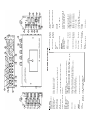
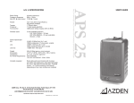
FMX-42
INSTRUCTIONS
4-CHANNEL PORTABLE MIXER
Azden Corporation
147 New Hyde Park Road
P.O. Box 10
Franklin Square, NY 11010
vox 516.328.7500 • fax 516.328.7506
[email protected] • www.azdencorp.com
Rev. 4
© Azden Corp. 2007
12
5
20
1
13
11
8
7
6
<0.005% @ 1 kHz (@ LINE position +19 dBu output)
16
T.H.D.
Balanced Output
4
-120 dBu (A weighted, Input Equivalent Level)
17
1400 g (without batteries)
49.3835 oz (without batteries)
Weight
Level
Line Input
Standard +4 dBu (electronically balanced)
Maximum > +26 dBu (=4 dBu position)
XLR 3-pin x 4 (CH1, 2, 3 and 4)
56H x 220W x 150.5D mm (without protrusions)
1.968H x 8.6614W x 5.9055D inches (without protrusions)
6 Alkaline “AA”
Approx. 10 hours (Meter Illum. OFF/Phantom Power OFF)
12VDC @ 200 mA
155 mA (Meter Illum. OFF/Phantom Power OFF - @ 9V)
195 mA (Meter Illum. OFF/Phantom Power ON w/2-SGM-1000 - @ 9V)
Dimensions
Balanced Input
21
INPUT
9
Power
Battery Requirement
Battery Runtime
External Power
Current Drain
18
Phantom Power Voltage 48V (± 4V)
10
Meters
Standard Output Level
Output Impedance Balanced
Unbalanced
0 VU (+4 dBu)
600 ohm
120 ohm
+1 dBu (32 ohm load)
16-100 ohm load recommended
Monitor Output
Maximum
1 kHz @ +4 dBu
Tone Generator
+4 dBu (> 10 k ohm load)
-2 dBu (600 ohm load)
+20 dBu (>10 k ohm load)
+13 dBu (600 ohm load)
-36 dBu (> 10 k ohm load)
-20 dBu (> 10 k ohm load)
Maximum
Standard
XLR 3-pin x 2 (Output L and R)
3.5 mm (1/8") Stereo mini-jack
6.5 mm (1/4") Stereo jack
Unbalanced Output Standard
Maximum
Level
Balanced Output
Balanced Output
Unbalanced Output
Monitor Output
OUTPUT
100 Hz – 6 dB/oct
20 k ohm
2 k ohm
Impedance
Line
Mic
High Pass Filter (HPF)
-50 dBu (electronically balanced)
-11 dBu
13
Mic (-50 position) Standard
Maximum
24
-30 dBu (electronically balanced)
+4 dBu
9
Signal-To-Noise
Balanced Output
26
Mic (-30 position) Standard
Maximum
22
20 Hz - 30 kHz (+0 / -1.5 dB)
30 Hz - 30 kHz (+0 / -2 dB)
25
3
Frequency Response
Balanced or
Unbalanced Output
Monitor Output
19
2
23
GENERAL
27
15
FMX-42 SPECIFICATIONS
14
OUTPUTS and SETTINGS
Monitor “LEVEL” and “MONITOR” Output Jack:
The “MONITOR” “LEVEL” (22) adjusts the volume of headphones connected to the
“MONITOR” output jack (23). Zero is the lowest (quietest) setting, 10 is the highest
(loudest).
Monitor “SELECT”:
Normally, the monitor “SELECT” switch (24) is set to position “L/R”. In this position
you will monitor the sound of all connected microphones using stereo headphones.
If you only want to hear the “L” output, use stereo headphones and set the switch to
position “L”. Or, if you only want to hear the “R” output, use stereo headphones and
set the switch to position “R”. The use of mono headphones is not recommended.
“OUTPUT” “L” and “R”:
Connect a cable from “OUTPUT” “L” (14) and/or “OUTPUT” “R” (15) to the microphone or line input of your video camera or audio recorder. These outputs accept
a standard 3-pin female XLR connector equipped cable. Push the cable connector
into the output jack until it locks. To remove the connector press the release tab on
the connector and pull the connector out.
“OUTPUT” “LEVEL” Settings:
Select the “OUTPUT” “LEVEL” (26) that is best-suited for your video camera or
audio recorder. The “+4 dBu” setting is for line-level audio inputs and the “-36 dBu”
setting is for a microphone-level audio input.
“STEREO” Mini-Connector Output:
The “STEREO” mini-connector (3.5 mm) output (25) is designed for video cameras
or audio recorders which have mini-connector microphone-level inputs.This output
is stereo (dual-channel) and unbalanced. It is recommended to use a stereo-tostereo mini-cable (not supplied) from the “STEREO” mini-connector output to the
microphone or line-level input of your video camera or audio recorder. Because
the FMX-42 has low-impedance XLR inputs and a mini-connector output, users of
mini DV cameras that have mini-connector microphone inputs can now use highquality microphones with XLR outputs.
“EXTERNAL DC IN”:
For external powering of the mixer, connect a power supply to this input (3).
Maximum rating of the power supply should not exceed 12 volts DC, 350mA.
Azden recommends using its BC-26U.
INTRODUCTION:
Thank you for purchasing Azden’s FMX-42 4-channel portable mixer. The FMX-42
has many unique features, making it very important to read and understand this
manual completely before use. Designed to work with most microphones that have
a low-impedance XLR output or line-level devices, the FMX-42’s output can be
connected to virtually any video camera or audio recorder, which has XLR or miniconnector mic/line inputs.
POWERING THE FMX-42
Battery Power:
Make sure the mixer is turned “OFF” (2). Remove the battery cover (1) by
pressing the clip in and then lifting up and removing the cover from the unit. Install 6
fresh “AA” ALKALINE batteries following the polarity diagram inside the battery
compartment. Do not force the batteries. When all 6 batteries are installed, replace
the battery cover and move the power switch (2) to the “BATT” position. The
“POWER” LED (4) will turn GREEN. When the battery voltage level becomes too
low for proper operation the “POWER” LED will turn RED. When this happens
replace the batteries with fresh, new “AA” ALKALINE batteries.When not in use,
turn the mixer “POWER” switch (2) to “OFF” to conserve battery life.
External Power:
The FMX-42 can be powered from an external power supply. After attaching the
power supply to an active 110VAC source and to the “EXT DC IN” jack (3) on the
FMX-42, move the power switch (2) to the “EXT” position. The “POWER” LED (4)
will turn green. When not in use, turn the mixer “POWER” switch to “OFF” and
disconnect the power supply from the mixer.
Note: The FMX-42 is not supplied with an external power supply. An optional power supply,
part number BC-26U, is available from Azden’s web site: www.azdencorp.com.
Wearing the FMX-42:
The FMX-42 is supplied with a ballistic nylon case. Place the mixer in the case and
adjust the neck strap to achieve the most comfortable position for you. A back
harness (not supplied) can be secured to the metal rings on the case for additional
support and comfort.
INPUTS and SETTINGS
“METER ILLUM”:
Turn this switch (27) “ON” to light up the VU Meters and set your audio levels.
Turn this switch “OFF” when not using the meters to conserve battery power.
“INPUT” Channels: “CH 1”, “CH 2”, “CH 3” and “CH 4”
Connect the output of a microphone, wireless receiver or line-level audio component to “INPUT CH 1” (5) and/or “CH 2” (5) and/or “CH 3” (5) and/or “CH 4” (5).
The inputs accept a standard 3-pin male XLR connector equipped cable. Push the
connector into the input jack until it locks. To remove the connector, press the
“PUSH” tab (6) and pull the connector out.
4
Illustration numbers:
1
Shown in the instructions within ( ), these numbers refer to the illustrations on the inside cover.
“INPUT LEVEL” Settings: “+4”, “-30 dBu”, “-50 dBu”
Each input channel of the FMX-42 has its own level setting (7). Select the input level
that is best suited for the microphone, wireless receiver or line-level audio component that you are connecting to each input. The “+4” setting is for line-level audio, “30 dBu” and “-50 dBu” are both microphone-level settings. For the microphonelevel settings, start with the “-30 dBu” position. If your microphone seems to have too
much gain (volume) try the “-50 dBu” setting.
“PHANTOM DC48V” Switch:
Each channel of the FMX-42 has its own “PHANTOM DC48V” power setting (8).
When using a dynamic microphone be sure to turn the corresponding “PHANTOM
DC48V” switch to the “OFF” position. When using a condenser microphone that
requires 48VDC external power, turn the corresponding “PHANTOM DC48V”
switch to the “ON” position. The “PHANTOM DC48V” only opterates in the “-30
dBu” and “-50” “INPUT LEVEL” position
WARNING: With the “PHANTOM DC48V” power turned “ON” the FMX-42 supplies
48VDC to the microphone. Please make sure that your microphone is designed to
handle 48VDC or you may damage it. Check the microphone’s user manual or with
the manufacturer of your microphone.
FRONT PANEL CONTROLS and SETTINGS
Input “LEVEL” Controls:
Each “INPUT” channel of the FMX-42 has an adjustable input “LEVEL” control (9)
(this is the inner-smaller control). This controls the input volume of the microphone
connected to each corresponding “INPUT”. Zero is the lowest (quietest) setting
while 10 is the highest (loudest). For the best sound with the lowest noise, increase
the input level control until the corresponding VU Meter (10) peaks at 0 dB.
Input “PEAK” Level LEDs:
Each “INPUT” channel of the FMX-42 has 2 “PEAK” level LEDs. These LEDs are
provided to help set precise input “LEVEL” adjustments. The LEDs are located to the
left of each input “LEVEL” control. The lower LED (11) indicates the level of the input
electronically prior to the “LEVEL” control. The upper LED (12) indicates the level
electronically after the “LEVEL” control. The lower LED (11) lighting RED indicates
that the item attached to the mixer’s “INPUT” has a signal that is too high and should
be reduced either by changing the “INPUT LEVEL” switch (7) or at the device itself.
The upper “PEAK” level LED (12) should only light RED occasionally. If this LED
stays lit continuously lower the input “LEVEL” (9) and/or change your “INPUT
LEVEL” (7) settings. These LEDs help reduce signal overload and distortion.
“PAN” Controls:
Each channel of the FMX-42 has an adjustable “PAN” control (13) (this is the outerlarger control). When the “PAN” control is in the center position, an equal amount of
sound will come from “OUTPUT” “L” (14) and “OUTPUT” “R” (15) for any microphone or line-level input connected to the corresponding “INPUT”. Moving the
2
“PAN” control left will decrease the sound output in the “R”ight channel. Moving the
“PAN” control right will decrease the sound output in the “L”eft channel.
“LIMITER” Switch:
Each “INPUT” channel of the FMX-42 has a switchable “LIMITER” (16). After
setting the input “LEVEL”, turn this switch to “ON”. The “LIMITER” circuit acts as a
safety and reduces the possibility of overload distortion from very loud sounds
without affecting normal sound volume. If you prefer the overall sound quality of the
mixer without the “LIMITER” circuit engaged leave the switch “OFF”.
“HPF” - High Pass Filter:
Each “INPUT” channel of the FMX-42 has a switchable high pass (low cut) filter “HPF” (17). This filter is useful for removing unwanted low frequencies, such as
wind and air-conditioning noise. For most applications engaging the high pass filter
will improve overall sound quality.
“MASTER” Level Control:
The “MASTER” knob (18) controls the overall volume of all connected sources
(microphones and/or line-level devices). For the best possible sound and lowest
noise, try to keep this control set at its midpoint while maintaining the VU meters at
their 0 dB range with the “input “LEVEL’ controls.
VU Meters - “L” and “R”
For the best sound, while keeping the “MASTER” control at its midpoint, increase or
decrease each channels “LEVEL” control (9) until the “L” and/or “R” VU meter (10)
peaks at 0 dB. If the ”LEVEL” is set too low, sound may be accompanied by
background hiss. If the “LEVEL” is set too high the sound may be distorted. Monitor
the sound with headphones and adjust the “LEVEL” for the best sound. A peak level
LED (19) will light RED if your overall levels are set too high.
“SLATE MIC”:
Press and hold this button (20) to engage the “SLATE MIC” (microphone). The
“SLATE MIC” is used to pick up audio at the mixer’s location and is not intended for
serious audio recording. It is however, very useful for notating scenes or other onlocation documentation .
“1 kHz TONE”:
Press and hold this button (21) to generate the 1 kHz tone. This output tone is used
to set the recording levels of your video camera or audio recorder to their optimum
level. While generating the 1 kHz tone, set the recording levels of your video camera
or audio recorder to the specified level as recommend in the owner’s manual. The
signal is generated at +4 dBu.
3