1
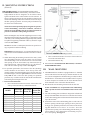
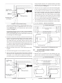
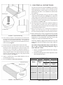
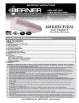
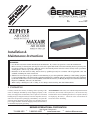
E NS
V
O
SA T I
D UC
N
A TR
S
D
A
N
E I
R E
ES
TH
No.:
Date:
II-470
October, 2007
Installation &
Maintenance Instructions
WARNING: TO REDUCE THE RISK OF FIRE, ELECTRIC SHOCK, OR INJURY TO PERSONS, OBSERVE THE
FOLLOWING:
A. Use this unit only in the manner intended by the manufacturer. If you have any questions, contact the manufacturer.
B. Before servicing or cleaning unit, switch power off at service panel and lock the service disconnecting means to prevent power
from being switched on accidentally. When the service disconnecting means cannot be locked, securely fasten a prominent
warning device, such as a tag, to the service panel.
C. Installation work and electrical wiring must be done by qualified person(s) in accordance with all applicable codes and
standards, including fire-rated construction.
D. Sufficient air is needed for proper combustion and exhausting of gases through the flue (chimney) of fuel burning equipment
to prevent back drafting. Follow the heating equipment manufacturer’s guideline and safety standards such as those published
by the National Fire Protection Association (NFPA), and the American Society for Heating, Refrigeration and Air Conditioning
Engineers (ASHRAE), and local code authorities.
E. When cutting or drilling into wall or ceiling, do not damage electrical wiring and other hidden utilities.
I. UNCRATING
ACCESSORIES: If the unit(s) were ordered with optional electrical
accessories (door switch, control panel, etc.), the accessories may
be found in the carton containing the unit or in a separate carton(s)
accompanying the unit(s). Check all of the cartons/skids for
accessories before discarding.
Carefully examine the carton(s) for damage before opening. If the
carton is damaged, immediately notify shipping company. If the
unit(s) were shipped on wooden skids, remove protective wood and
banding straps securing the carton(s) to the skid. Open the carton(s)
and remove all protective packaging. Immediately verify that the
electrical rating nameplate located on the cover matches electrical
power supply available. Retain the shipping carton(s) until the unit(s)
are installed and properly operating.
BERNER INTERNATIONAL CORPORATION
New Castle, Pennsylvania
724-658-3551
●
1-800-245-4455
●
www.berner.com
© Copyright 2007 Berner International Corporation
-1-
●
[email protected]
II. MOUNTING INSTRUCTIONS
(General)
INDOOR MOUNTING - Environmental/Insect/Dust Control
OUTDOOR MOUNTING (Unheated Only)- Insect/Dust Control
Zephyr/Maxair air door is designed to be an effective barrier
against cold drafts in the winter and hot air in the summer. To
achieve optimum protection, the unit should be mounted on the
inside of the building, flush to the wall and as close to the top of
the door opening as possible. To ensure peak performance keep
air stream free of obstructions.
The air door will not perform properly if negative air pressure
exists in the building. Under these conditions, a means for
makeup air to the building must be provided so that the air
pressure on both sides of the opening is in balance.
Before mounting the unit, check the supporting structure to verify
that it has sufficient load-carrying capacity to support the weight
of the unit(s). The mounting hardware (supplied by others) should
be capable of supporting a minimum of three (3) times the weight
of the unit. See Table 1.
NOTE: The air door is weatherproof, therefore no special covering is required for outdoor mounting.
IMPORTANT: A minimum of 1” is recommended above the top
of the air door for the installation and removal of the cover housing.
A. When determining the mounting location for the unit(s), make
sure that nothing interferes with the curtain of air developed
when the discharge vanes are directed from 0º to 20º toward the
door opening. If the air stream strikes any obstruction (the top
edge of the doorway, a door opening device, etc.), the effectiveness of the unit will be greatly reduced. See Figure 1
B. For optimum performance, the bottom of the unit (discharge
nozzle) should be no more than 1” above the top of the door
opening with the unit mounted flush to the wall. If the unit must
be mounted higher, it must be spaced out from the wall 3/8” for
every inch the unit is above the door opening. For optimum
protection, any void between the air door and the wall should be
sealed along the full length of the unit.
C. Electric heated units shall:
1. Have a minimum clearance of at least 1” between the sides
and top of the unit and any combustible material.
MODEL
ZPR/MAX1030
ZPR/MAX1036
ZPR/MAX1042
ZPR/MAX1048
ZPR/MAX1060
ZPR/MAX1072
ZPR/MAX2084
ZPR/MAX2096
ZPR/MAX2120
Net Weight Net Weight
Ambient (lbs) Heated (lbs)
33
38
43
48
57
64
86
96
124
40.5
45.5
50
56
75
76.5
100
111.5
145.5
TABLE 1 - Unit Weight
FIGURE 1 - Mounting Location
2. Have a minimum clearance of at least 6’ between the bottom of the unit and the floor.
3. Be installed indoors only.
D Proceed to either Section III-WALL MOUNTING, or Section IV
SUSPENDED MOUNTING
III.
A. The ZPR/MAX Series Air Door is equipped with two ¼” threaded
inserts on the back of each unit (two per module on units 84” and
over). Insert and tighten the shoulder bolts (provided) into these
threaded inserts. A minimum of two shoulder bolts are required,
on units comprised of modules use the outer threaded inserts
and a minimum of one of the inner threaded inserts.
B. Determine the exact mounting location of the air door unit.
NOTE: A minimum of ¾” is required above the wall mounting
plate to provide clearance for installation and removal of the
unit.
Net Weight
Steam/Hot
Water (lbs)
39
48
55
62
75
87
113
127
163
WALL MOUNTING
C. The wall mounting plate (included) is designed to fit flush with
the top of the ZPR/MAX Series Air Door. Therefore the location
of the wall mounting plate will determine the final location of the
top of the Air Door.
D. Position the center of the wall mounting plate over the center of
the door opening with the larger opening of the key hole slots
facing up. For optimum performance, the bottom of the mounting plate should be no more than 2” or less than 1” above the
top of the door opening. The wall mounting plate thickness provides a natural ¾” space which allows for mounting it up to 4”
above the opening. See Figure 2
-2-
rating nameplate. Remove the required knockouts and attach
necessary electrical hardware. Save the wiring diagram found
inside of wiring tray. See Figure 7
I. There are two sets of keyhole slots on the wall mounting plate.
In low overhead installations the air door may be staged in the
lower keyholes to provide clearance for electrical wiring and
then moved to the higher holes after completion. Raise the air
door with the discharge opening facing down toward the floor.
While holding the unit level, slide the heads of the shoulder
bolts into the larger hole of the keyhole slots of the mounting
plate. Lower the unit into place, keeping both ends level, allowing it to rest flush with the mounting plate. See Figure 4
J. After attaching the unit to the mounting plate, ensure that the
unit is seated and flush with the mounting plate on all four sides.
K. Proceed to Section V - Electrical Connections.
FIGURE 2 - Standard Wall Mounting
If the wall mounting plate must be mounted higher than 4” above
the door opening, it must be spaced out from the wall 3/8” for
every additional inch (over 4”) that the unit is above the door
opening. See Figure 3
For optimum protection, do not exceed the recommended maximum mounting height of 8’ above the finished floor. Any void
between the mounting plate and the wall should be sealed along
the full length of the mounting plate.
E. Determine which of the four holes provided in each of the steel
brackets of the wall mounting plate are located where suitable
support is available for the unit. Minimum one inside hole and
one outside hole from each bracket must be used for proper
support. Drill out the aluminum backing of the holes chosen with
a ¼” drill bit. If the provided holes on the mounting plate are not
located where suitable support is available, drill new holes in the
space provided on the steel mounting brackets.
FIGURE 4 - Installing Air Door on Wall Mounting Plate
F. Mark the wall in the centers of the ¼” holes drilled on the mounting plate.
IV.
G. Attach the mounting plate to the wall (hardware by others).
SUSPENDED MOUNTING
(Ceiling Suspension)
H. The top of the unit is provided with two knockouts on each side
allowing for a left or right hand power connection. Remove the
wiring tray cover; on units that are comprised of modules, remove the wiring tray cover that is located closest to the electrical
A. When the unit is top mounted, the wall mounting plate is designed to store on the back of unit for future use. See Figure 5
FIGURE 3 - High Wall Mounting
FIGURE 5 - Wall Mounting Plate Storage
-3-
V. ELECTRICAL CONNECTIONS
All electrical wiring and connections MUST be performed by
qualified personnel in accordance with the National electrical
Code ANSI/NFPA No. 70 (latest edition) or, in Canada, the Canadian Electrical Code, Part 1-C.S.A. Standard C22.1 and local codes
and regulations.
A. Check the rating nameplate on the top of the unit for supply
voltage and current requirements. See Figure 7. A separate line
voltage supply with a suitable branch circuit protection device
should be run directly from the main electrical panel to the unit.
A disconnect switch for each branch circuit is a required part of
this installation. See Tables 2 & 3
B. All field wiring must be copper with a minimum insulation of
60°C within approved conduit. If any of the wire supplied with
the unit must be replaced, it must be replaced with copper wiring
with a minimum insulation of 90°C.
C. Remove the wiring tray cover; on units that are comprised of
modules, remove the wiring tray cover that is located closest to
the electrical rating nameplate (if it has not already been done).
FIGURE 6 - Suspended Mounting
B. Four (4) factory installed ¼” threaded inserts are located on the
top of the unit for top suspension mounting; on units comprised
of modules use the outer threaded inserts. To eliminate the
slight deflection of longer units, the inner threaded inserts may
also be used. See Figure 6
D. Electric heated units are factory equipped with a unit mounted
solid state temperature sensor cable (for the Intelliswitch
thermostat) located in the wiring tray. Depending where the
temperature is to be measured; the sensor may be left in the
wiring tray or it may be located outside of the unit.
If the unit is unheated, equipped with a steam/water coil or the
sensor will be left in the wiring tray, skip to step E, otherwise
continue.
C. Determine the exact mounting location of the air door unit.
Note: Sensor storage temperature range is -76º F to 302º F (60º C to 150º C). Sensor functioning temperature range is
32ºF to 100ºF (0º C to 38Cº).
D. The top of the unit is provided with two knockouts on each side
allowing for a left or right hand power connection. Remove the
wiring tray cover; on units that are comprised of modules, remove the wiring tray cover that is located closest to the electrical
rating nameplate. Remove the required knockouts and attach
necessary electrical hardware. Save the wiring diagram found
inside of wiring tray. See Figure 7
1.
2.
Remove 1/2" bushing taped to the back of the wiring tray
cover and set aside.
Determine mounting location of the temperature sensor
(do not mount at this time).
E. Attach ¼” threaded rods, or other suitable hardware to the top
mounted threaded inserts.
F. Proceed to Section V - Electrical Connections
Model
ZPR/MAX1030
ZPR/MAX1036
ZPR/MAX1042
ZPR/MAX1048
ZPR/MAX1060
ZPR/MAX1072
ZPR/MAX2084
ZPR/MAX2096
ZPR/MAX2120
FIGURE 7 - Electrical Connections
MOTOR DATA
120 V
1ø
#Motors
@HP
Total Motor
Amps
1@1/5
1@1/5
1@1/5
1@1/5
1 @1/5
1@1/5
2@1/5
2@1/5
2@1/5
3.4
3.4
3.4
3.4
3.4
3.4
6.8
6.8
6.8
TABLE 2 - Motor Amp Draw
-4-
208/240 V
1ø
Total Motor
Amps
1.7
1.7
1.7
1.7
1.7
1.7
3.4
3.4
3.4
ELECTRIC HEATER DATA*
Add total motor amp draw from Table #2 to circuit #1 for unit total amp draw
480V 3Ø**
208V 3Ø
240V 3Ø
208V 1Ø
240V 1Ø
Amp Draw
Amp Draw
Amp Draw
Amp Draw
Amp Draw
Circuit 1 Circuit 2 Circuit 1 Circuit 2 Circuit 1 Circuit 2 Circuit 1 Circuit 2 Circuit 1
600V 3Ø**
Amp Draw
Circuit 1
MODEL
KW
ZPR/MAX1030
5.4
26.0
N/A
22.5
N/A
N/A
N/A
N/A
N/A
N/A
N/A
ZPR/MAX1030
7.2
34.6
N/A
30.0
N/A
N/A
N/A
N/A
N/A
N/A
N/A
ZPR/MAX1036
10
48.0
N/A
41.7
N/A
27.8
N/A
24.1
N/A
12.0
10.0
ZPR/MAX1042
10
48.0
N/A
41.7
N/A
27.8
N/A
24.1
N/A
12.0
10.0
ZPR/MAX1048
14.4
34.6
34.6
30.0
30.0
40.0
N/A
34.6
N/A
17.3
14.6
ZPR/MAX1060
14.4
34.6
34.6
30.0
30.0
40.0
N/A
34.6
N/A
17.3
14.6
ZPR/MAX1072
20
N/A
N/A
N/A
N/A
27.8
27.8
24.1
24.1
24.0
20.1
ZPR/MAX2084
20
N/A
N/A
N/A
N/A
27.8
27.8
24.1
24.1
24.0
20.1
ZPR/MAX2096
28.8
N/A
N/A
N/A
N/A
40.0
40.0
34.6
34.6
34.6
28.9
ZPR/MAX2120 28.8
N/A
N/A
N/A
N/A
40.0
40.0
34.6
34.6
34.6
*Optional kW available. Check wiring diagram supplied with unit for kW and AMP draw if not listed above.
** Separate 120V, 208V or 240V single phase circuit required to operate motors rated in Table 2.
28.9
TABLE 3 - Electric Heater Amp Draw
3.
4.
5.
Choose end of the wiring tray that the sensor will exit the
unit based on mounting location from step 2.
Locate the 1/8" hole on wiring tray next to the electrical
knockout on the side determined in step 3.
Drill out 1/8" hole to 1/2".
CAUTION: DO NOT DAMAGE EXISTING WIRES IN
THE WIRING TRAY WHEN DRILLING
6.
7.
8.
Maneuver the tip of the temperature sensor from the inside
through 1/2" hole.
Thread tip through 1/2" bushing from step 1 and snap
bushing into wiring tray.
Mount temperature sensor. Do not put any clamps on
rubber coated tip.
1.
2.
3.
4.
5.
6.
E. The top of the unit has two knockouts on each side allowing for
a left hand or right hand power connection. Remove the required
knockout, if it has not already been done, and connect the power
supply to the unit. Connect all supply and control circuit wires
according to wiring diagram provided.
NOTE: Polarized rib on the serial cable faces up to
straddle locking ramp on 4-pin header. Ensure that all
cable connections are locked onto headers.
NOTE: It does not matter which port is used for either
case because each serial port supports two way
communication to other Intelliswitches.
NOTE: For Electric heated units provided with optional remote
thermostat. Mount and wire the thermostat according to instructions and wiring diagram.
7.
F. Master/Slave connection, if two or more units are to be linked
together for master/slave operation continue, otherwise skip to
step G.
NOTE: One Intelliswitch serial cable (part no. 505SC485INT)
is required for every unit that is to be used as a slave.
For master/slave operation a serial cable connection must be
made between the Intelliswitch control boards of each unit to
be linked.
-5-
Disconnect the power to all units.
Access the Intelliswitch control board by removing two
phillips head screws from the Intelliswitch display
faceplate. Remove the faceplate from the control board by
grasping it firmly and gently pulling it away from the unit.
Locate 1" hole in wiring tray directly above control board.
Guide one end of serial cable(s) through this hole, behind
the motor and over the control board.
Locate the two 4-pin headers (four pin male connectors)
marked J4 and J5 positioned to the right of the 8-pin header
for the display board.
For the first and last unit connect serial cable to either J4
or J5. For each unit in between connect one serial cable to
J4 and one serial cable to J5.
Reinstall display faceplate by aligning 8-pin socket holes
on the back of display board with 8-pin header on control
board. Push gently and firmly (confirming all pins are
inserted) until face plate rests against mounting bracket.
Insert and tighten two phillips head screws.
NOTE: Align faceplate mounting holes with threaded
mounting holes on unit before pushing faceplate onto pins.
This should help to align the pins with the socket.
8.
The units are now linked in a Master/Slave configuration.
For operation of units in a Master/Slave configuration see
Section IV Operation and Controls.
j.
Locate male end of ribbon cable and run it to the
remote display location. The cable is minimum CL2
rated and should not need to be in conduit.
k. Connect the male end of the ribbon cable to the 8-pin
socket through the back of the display board with the
cable approaching from the bottom and the red ribbon
indicator to the right (when facing the back of the
display board).
l. Mount remote faceplate to wall.
m. Install blank switch cover onto unit using screws from
faceplate.
G. Remote mounted Display Faceplate, if operation of the
Intelliswitch is desired through a remote mounted display
faceplate continue, otherwise skip to step H.
NOTE: Maximum mounting distance between the display
faceplate and the unit is 20’.
If the unit was factory ordered with the remote mounted faceplate
option then proceed to step 1, to field convert a unit mounted
Display Faceplate to a remote mount proceed to step 2.
1. Factory Ordered Remote Mounted Display Faceplate
a. When the remote faceplate option is ordered from the
factory the unit comes equipped with the blank
faceplate and 12' ribbon attached. The display faceplate
is shipped loose ready for field installation.
b. Locate the male end of the 8-conductor ribbon cable
in the wiring tray and run it to the remote display
location. The cable is minimum CL2 rated and should
not need to be in conduit.
c. Connect the male end of the ribbon cable to the 8-pin
socket through the back of the display board with the
cable approaching from the bottom and the red ribbon
indicator to the right (when facing the back of the
display board).
d. Mount remote faceplate to the wall.
2.
Field Conversion of Unit Mounted Display Faceplate to
Remote Mount
H. Reinstall wiring tray cover.
I.
Proceed to Section VI-Mechanical Connections for Electric,
Steam and Hot Water units other wise proceed to Section VIIOperation and Controls.
VI. MECHANICAL CONNECTIONS
A. ELECTRICALLYHEATED MODELS
The heater circuit may be controlled by a remote thermostat or
manually through the switch located on the discharge side of
the unit. Overheating protection is provided by auto reset thermal cutouts built into the heater coil assembly (see the wiring
diagram).
B. STEAM OR HOT WATER HEATED MODELS
Piping should be done in accordance with local codes, regulations and standard practices. Connect the building system supply & return to the ¾” MPT nipples on the heating coil. See
Figure 8
NOTE: One Intelliswitch remote mounting kit (PART #
33G020RDK-A) is required for every unit that will have
a remote mounted faceplate.
a. Disconnect the power to all units.
b. Access the Intelliswitch control board by removing
two phillips head screws from the Intelliswitch display
faceplate. Remove the faceplate from the control board
by grasping it firmly and gently pulling it away from
the unit.
c. Flip the faceplate over and place it on a clean soft
surface.
d. Remove the two phillips head screws holding the
display board to the faceplate. If one of the screws
uses two fiber washers, save them for the replacement
board.
e. Install display board onto remote faceplate with
existing screws and washers.
f. Locate 1" hole in wiring tray directly above control
board.
g. Guide the female end of the 8-conductor ribbon cable
through this hole, behind the motor and over the
control board.
h. Locate the 8-pin header for the display board on the
control board marked J1.
i. Connect female end of the ribbon cable to 8-pin header
on the control board with red ribbon indicator located
on the left for pin #1.
FIGURE 8 - Steam/Hot Water Connections
VII. OPERATION AND CONTROLS
A. The Intelliswitch is a user programmable microprocessor
controller that lets the user control all aspects of the Zephyr/
Maxair air door.
1.
Unit/Remote Mounted Display
Press “Menu” button to navigate features
Press “Arrows” to adjust/change settings, all settings rollover
-6-
b.
3.
External Connections
a.
Remote Mounted Thermostat:
A remote mounted thermostat
may be connected to wires 6
& 7 of the Intelliswitch. If the
internal thermostat is left on,
the external thermostat will
work with it in parallel,
allowing either one to activate the heat. If the internal
thermostat is turned off, the external thermostat will
work independently to activate the heat.
b.
Auto Mode Activation: The Intelliswitch may be
activated externally through the Auto mode by means
of an external set of dry contacts (typically a door
switch) connected to wires 9 & 10.
NOTE: hold arrow down to scroll values faster for time
and temperature settings
NOTE: If after any Menu or setting change there is no
activity for 15 seconds the control will save changes and
default back to display clock.
•
•
•
•
•
Lock/Unlock: hold up and down arrows simultaneously
for 10 seconds to lock control (when locked, features
maybe viewed, but settings cannot be changed)
Fan Speed: settings range from 1 thru 10 (1=low speed,
10=high speed)
Mode:
Off - unit off
On - unit will come on when Start/Stop Time is satisfied
(see below)
Auto - unit will come on with external contact closure
(typically a door switch) and when Start/Stop Time is
satisfied (see below), unit will shut off when external
contact opens
Delay Time: settings range from 1 second - 10 minutes in
increments of seconds, active in Auto mode only, this will
delay the time that it takes the unit to turn off after the
external contact opens
NOTE: Set to “Off” position to disable
Temp Set:
First - temperature units setting (F - Fahrenheit, C Celsius)
Second - temperature settings range from 50º - 90º F (10º32º C), displays temperature setting for built in thermostat
(when temperature falls below setting, heat will come on)
•
•
2.
Master/Slave Operation
For master/slave operation a serial cable connection must
be made between the Intelliswitch control boards of each
unit to be linked.
Once units are linked, all Menu setting changes made on
all units through the display faceplate or hand held remote
will transfer to all other linked units.
NOTE: Changes do not take effect until the Menu button
is pressed to advance to the next option or after the control
returns to clock display.
B. Rotary Variable Switch Control
Rotate the dial counter clockwise to turn on the unit. Fan speed
starts at high and decreases to low. The heat will also be
energized on units with an optional electric heater. A thermostat
may be used to cycle the heat on and off.
VIII. AIRFLOW ADJUSTMENTS
A. With the air door operating and the door in its full open position, check to see that nothing is obstructing the air flow at the
discharge nozzle vanes.
NOTE: The internal thermostat may be disabled by setting it
to the off position located between the 90º and 50º (32º
and 10º C) settings
•
4.
The hand held remote will
change any of the settings
when the display is locked.
Start Time: sets the time when the unit is to turn on in the
“On” mode or become active for “Auto” mode (based on
time clock setting, note the “am” indicator)
Stop Time: sets the time when the unit is to turn off in the
“On” mode or become inactive for the “Auto” mode
(based on time clock setting, note the “am” indicator)
Set Time: sets the clock (note “am” indicator), does not
adjust for daylight savings
B. Find the air stream split location. Hold a handkerchief, by its
corners, approximately 12” above the floor. Gently move the
handkerchief back and forth in the doorway. Make sure the air
is being directed to both the inside and the outside. See Figure
9. The split location is indicated where the handkerchief is vertical with minimal or no fluttering.
C. Adjust the discharge nozzle vanes so the split location is approximately 3” outside the doorway. Adjust the speed controller
so that the split location is approximately 12” above the floor.
Hand Held Infrared Remote Control
IX. MAINTENANCE AND CLEANING
Operation of the hand held remote is the same as the
Unit/Remote Mounted Display with two exceptions.
a.
CAUTION: ELECTRIC SHOCK HAZARD Disconnect power
whenever servicing unit. More than one disconnect may be
required to de-energize unit.
The addition of a lock button to lock the display
board.
-7-
B. Remove the bottom access panel by removing the phillips head
screws on the bottom of the unit.
C. Vacuum and scrape (if necessary) to remove the buildup of dirt
and debris. The motor(s) are permanently lubricated and require
no additional lubrication. Reinstall the cover and intake grille.
D. Switch the power on after cleaning. CAUTION: STAND CLEAR
OF THE UNIT OR WEAR SAFETY GOGGLES AS LOOSE DEBRIS MAY BE PRESENT AND MAY EXIT THE NOZZLE.
X.
SERVICE
CAUTION: ELECTRIC SHOCK HAZARD Disconnect power
whenever servicing unit. More than one disconnect may be
required to de-energize unit.
Any service performed on the ZPR/MAX Series air door MUST
be done by qualified personnel.
Berner air doors require very little servicing. All parts are easily
accessible for periodic inspection and maintenance. Units should
be cleaned at least twice a year. Your particular application (the
amount of dirt and dust in the air) and location of the unit(s) will
determine how often your unit(s) will need to be cleaned and
serviced. All motors have permanently lubricated, sealed, sleeve
bearings and require no maintenance. See Figure 11
FIGURE 9 - Airflow Adjustment
Keep your air door operating at peak efficiency by cleaning the
blower wheels, motor(s) and intake grille. Buildup of dust on the
blower wheels can cause vibration, noise and excessive wear on
the motor bearings. The frequency of cleaning will depend on
the environment where the unit is operating.
Dirty, dusty or greasy environments could require a cleaning
schedule of once every two months. If the environment is not
that dirty, the unit(s) should be scheduled for cleaning a minimum of once every (6) months. To access the interior of the unit:
A. Disconnect the power to the unit; remove the intake grille by
removing the locking screws on each end of the unit. Lift the
intake grille up and then towards you. See Figure 10.
FIGURE 11 - Unit Components
A. INTELLISWITCH DISPLAY BOARD REMOVAL OR
REPLACEMENT
CAUTION: Do not expose the bare board to static electricity,
water, extreme heat or extreme moisture.
1.
2.
3.
4.
5.
6.
7.
8.
FIGURE 10- Intake Grill Removal
-8-
Set Intelliswitch mode to off.
Disconnect power to the unit.
Remove the two phillips head screws from the Intelliswitch
display faceplate.
Remove the faceplate from the control board by grasping
it firmly and gently pulling it away from the unit.
Flip the faceplate over and place it on a clean soft surface.
Remove the two phillips head screws holding the display
board to the faceplate. If one of the screws uses two fiber
washers, save them for the replacement board.
Install new display board onto faceplate with existing
screws and washers.
Reinstall display faceplate by aligning 8-pin socket holes
on back of display board with 8-pin header on control
board. Push gently and firmly (confirming all pins are
inserted) until face plate rests against mounting bracket.
Insert and tighten two phillips head screws.
Note: Align faceplate mounting holes with threaded
mounting holes on unit before pushing faceplate onto pins.
This should help to align the pins with the socket.
B. INTELLISWITCH CONTROL BOARD REMOVAL OR
REPLACEMENT
CAUTION: Do not expose the bare board to static electricity,
water, extreme heat or extreme moisture.
NOTE: The Intelliswitch Control Board may be removed
without removing the bottom access cover or transverse.
However removal of the bottom access cover and transverse
will simplify the process.
1.
2.
3.
Set Intelliswitch mode to off.
Disconnect power to the unit.
Remove the two phillips head screws from the Intelliswitch
display faceplate.
4. Remove the faceplate from the control board by grasping
it firmly and gently pulling it away from the unit.
5. Mark and remove all wires connected to the control board.
6. Remove the two phillips head mounting screws that attach
the control board to the unit frame.
7. Carefully maneuver the control board out of the unit by
sliding straight down. Avoid contact between board
components and the motor mount.
8. Remove the two phillips head screws that attach the control
board to the mounting bracket.
9. Attach mounting bracket to the new control board with
existing screws.
10. Install new control board into the unit by carefully sliding
the two tabs at the top of the control board into the two
corresponding slots in the unit frame and fasten with flat
head screws. Note: when the tabs of the board hit the unit
frame tip the board up and angle the tabs into the slots.
11. Reconnect all wires to the control board.
12. Reinstall display faceplate by aligning 8-pin socket holes
on back of display board with 8-pin header on control
board. Push gently and firmly (confirming all pins are
inserted) until face plate rests against mounting bracket.
Insert and tighten two phillips head screws.
NOTE: Align faceplate mounting holes with threaded
mounting holes on unit before pushing faceplate onto pins.
This should help to align the pins with the socket.
C. INTELLISWITCH SPEED SENSOR REPLACEMENT
1. Set Intelliswitch mode to off.
2. Disconnect power to the unit
3. Remove the intake grille by removing the locking screws
on each end of the unit. Lift the intake grille up and then
away from the unit.
4. Remove the bottom access panel by removing the phillips
head screws on the bottom of the unit.
-9-
5.
Remove the two phillips head screws from the Intelliswitch
display faceplate.
6. Remove the faceplate from the control board by grasping
it firmly and gently pulling it away from the unit.
7. Disconnect the speed sensor from the control board by
locating the pin connection marked J2 and labeled
PROXIMITY. Grasp the socket and carefully pull away
from the control board.
8. Remove the 13 mm hex nut and washer closest to the fan
from the sensor.
9. Remove the sensor.
10. Connect the new sensor to the control board, secure all
loose wires from rotating parts.
11. Install new sensor into mounting bracket. Use the 13 mm
nuts to position the tip of the sensor a maximum of 5/64"
(2 mm) away from the rotating trigger located on the motor
shaft. When the unit is energized, the LED on the back of
the sensor will illuminate when the trigger passes if the
correct distance has been set.
CAUTION: Do not mount the speed sensor too close to
the trigger, the sensor will be ruined if it is struck by the
trigger.
12. Reinstall display faceplate by aligning 8-pin socket holes
on back of display board with 8-pin header on control
board. Push gently and firmly (confirming all pins are
inserted) until face plate rests against mounting bracket.
Insert and tighten two phillips head screws.
NOTE: Align faceplate mounting holes with threaded
mounting holes on unit before pushing faceplate onto pins.
This should help to align the pins with the socket.
13. Reinstall remaining components in reverse order of
removal.
D. INTELLISWITCH SPEED SENSOR ADJUSTMENT
1.
2.
3.
4.
5.
6.
Set Intelliswitch mode to off.
Disconnect power to the unit
Remove the intake grille by removing the locking screws
on each end of the unit. Lift the intake grille up and then
away from the unit.
Remove the bottom access panel by removing the phillips
head screws on the bottom of the unit.
The speed sensor is held in with two 13 mm hex nuts and
a star washer.
Use the 13 mm nuts to position the tip of the sensor a
maximum of 5/64" (2 mm) away from the rotating trigger
located on the motor shaft. When the unit is energized,
the LED on the back of the sensor will illuminate when the
trigger passes if the correct distance has been set.
CAUTION: Do not mount the speed sensor too close to
the trigger, the sensor will be ruined if it is struck by the
trigger.
7.
Reinstall remaining components in reverse order of
removal.
E.
INTELLISWITCH TEMPERATURE SENSOR
REPLACEMENT
G.
1.
2.
3.
1.
2.
3.
Set Intelliswitch mode to off.
Disconnect power to the unit.
Remove the two phillips head screws from the Intelliswitch
display faceplate.
4. Remove the faceplate from the control board by grasping
it firmly and gently pulling it away from the unit.
5. Disconnect the temperature sensor from the control board
by locating the pin connection marked J3 and labeled TEMP.
Grasp the socket and carefully pull away from the control
board.
6. Remove the wiring tray cover.
7. Cut necessary cable ties.
8. Remove the temperature sensor.
9. Install new temperature sensor and all necessary cable
ties.
10. Reinstall display faceplate by aligning 8-pin socket holes
on back of display board with 8-pin header on control
board. Push gently and firmly (confirming all pins are
inserted) until face plate rests against mounting bracket.
Insert and tighten two phillips head screws.
4.
5.
6.
7.
8.
9.
10.
11.
NOTE: Align faceplate mounting holes with threaded
mounting holes on unit before pushing faceplate onto pins.
This should help to align the pins with the socket.
12.
11. Reinstall remaining components in reverse order.
F.
FANAND MOTOR REMOVAL
13.
UNIT MOUNTED ROTARY SWITCH REMOVAL
The variable speed switch can be removed directly from the
bottom of the unit.
14.
1.
2.
15.
3.
4.
5.
6.
Disconnect power to the unit.
Firmly grip the knob on the switch and gently pull to remove.
Use a phillips head screwdriver to remove the two screws
from the name plate.
Remove the two phillips head screws holding the switch to
the unit.
Remove the switch by pushing it into the unit and rotating
it gently end over end and sliding it out of the opening.
Reinstall in reverse order of removal.
Set Intelliswitch mode to off.
Disconnect power to the unit.
Remove the intake grille by removing the locking screws
on each end of the unit. Lift the intake grille up and then
away from the unit.
Remove the bottom access panel by removing the phillips
head screws on the bottom of the unit.
Remove the transverse by removing the four(4) 5/16” hex
washer head bolts.
Rotate the speed sensor bracket away from the motor by
removing the phillips screw farthest from the motor and
loosening the second phillips screw. Do not remove the
speed sensor from the bracket.
Unplug motor harness from motor and remove necessary
wiring.
Using a 1/8” Allen wrench, loosen each set screw attaching fan(s) to motor.
While holding the motor in place, loosen and remove the
motor clips.
Slide the fans toward the motor so that the ball bearings on
the outer fan shaft are exposed.
Slowly roll the motor out of the motor mount cradle forward and down. The hubs of the fans are flexible enough
to allow the motor to move before the fans’ outer ball bearings pull out of the unit.
If the unit equipped with an intelliswitch, remove the trigger bar from the motor shaft with a 5/64” allen wrench.
Install the trigger bar on the replacement motor so that it is
not closer than 0.030” to the motor bearing cap (including
shaft movement).
Ensure the trigger does not contact the speed sensor.
Maximum gap distance between trigger and sensor is 5/
64” (2mm).
Reinstall in reverse order of removal.
H. REPLACEMENTOFELECTRIC HEATER ELEMENT
1.
2.
3.
4.
5.
6.
- 10 -
Disconnect power to the unit, remove the intake grille by
removing the locking screws on each end of the unit. Lift
the intake grille up and away from the unit.
Remove the bottom access panel by removing the phillips
head screws on the bottom of the unit.
Remove and mark all wires from damaged element.
To remove damaged element from unit, drill out rivets and
remove screws.
Install new element and connect all wires.
Reinstall cover and intake grille.
TROUBLESHOOTING
SYMPTOMS
NO AIR
CAUSE
•
Power supply line open (no power)
•
•
•
Fuse blown/circuit breaker tripped
Motor overload tripped
•
•
• Failed switch
MOTOR RUNNING/FANS ARE NOT ROTATING
• Broken or damaged flexible hub
• Shaft rotating inside fan
REMEDY
•
Check power source, check method of control in ON
position
Replace fuse(s)/reset breaker
Internally protected motor - should reset automatically
after cool-down, if not, replace motor.
Replace switch
•
•
Replace fan sleeve/reengage coupling
Tighten set screws/tighten fan on shaft
ELECTRICAL CONTROLS NOT FUNCTIONING WHEN DOOR IS OPEN
• Turn switch to “ON” position
Selector switch is in off position
• Repair or replace limit switch
Door limit switch not operating
•
•
•
•
•
•
•
•
•
Adjust vanes to proper position, see instructions
Move air curtain or remove obstruction
Provide adequate space for air curtain
Improper voltage
Free fan from housing
Clean and vacuum fan wheels
Check fans for blade curve toward discharge
Speed sensor not detecting
trigger rotation
•
Adjust gap between sensor & trigger/
replace sensor
•
Air stream too weak
•
•
Air steam hits obstruction
•
•
Negative pressure
•
Adjust nozzle to proper position, adjust motor speed; see
installation instructions
Remove obstruction or reposition air curtain (move out
3/8” for every 1” up from the door)
Relieve negative pressure by providing makeup air
UNEVEN AIR
•
•
Shaft rotating inside fan
One motor not operating
•
•
Tighten set screws
Repair or replace motor
EXCESSIVE AIR
MOVEMENT AT DOORWAY
•
•
•
•
Nozzle not angled out far enough
Unit too powerful
Air movement too cold
Pushing air outside building
•
•
•
•
Adjust nozzle angle to outside
Adjust motor speed
Add auxiliary heat to overcome wind chill factor
Adjust discharge angle back into building, adjust motor
speed
•
•
Air directional discharge vanes mis-adjusted
Inadequate intake clearance
•
•
•
•
Blower motor operates below speed
Fan rubbing against housing
Fan wheels clogged with dirt
Fan in backwards
NO SPEED
ADJUSTMENT
•
AIR IS NOT HITTING
FLOOR
MINIMUM AIR
SEE AIR IS NOT HITTING FLOOR SYMPTOMS
ELECTRICALLY HEATED MODELS
•
•
•
•
•
•
•
Switch turned to “ON” position
Thermostat not set properly
Coils burned out due to lack of air
Automatic reset thermal cutout failed in open position
Manual reset thermal cutout tripped (if supplied)
Speed sensor not detecting trigger rotation
Without speed adjustment, failed speed sensor
•
•
•
•
•
•
•
Replace switch or check wiring
Change thermostat setting
Correct airflow problem; replace coils
Replace automatic thermal cutout
Reset manual thermal cutout
Adjust gap between sensor and trigger
Replace speed sensor
•
•
Move thermostat away from air stream
•
•
•
Thermostat in wrong location - thermostat too
close to discharge
Improper voltage
Thermostat not set properly
Speed sensor not detecting trigger rotation
•
•
•
Supply proper voltage
Change temperature setting
Adjust gap between sensor & trigger/replace sensor
•
•
•
•
•
Incorrect speed range
Thermostat in wrong location
Thermostat not set properly
Insufficient air over coil
Improper voltage
•
•
•
•
•
Set dip switch to electric heated speed range
Move the thermostat closer to air stream
Change temperature setting
Remove restriction on intake
Supply proper voltage
EXCESSIVE HEAT
•
•
Too high steam/hot water pressure
Inadequate air flow, fins plugged up, dirty coils
•
•
Reduce steam pressure/hot water flow
Clean intake and coils
MINIMAL HEAT
•
•
•
Insufficient removal of condensation (steam)
Not enough steam pressure/water temperature too low
Intake air below design temperature
•
•
•
Increase trap size
Raise pressure for steam/increase water flow
Increase steam pressure/increase water flow
NO HEAT
MINIMAL HEAT
EXCESSIVE HEAT
STEAM/HOT WATER HEATED UNITS
- 11 -
WARRANTY
Berner International warrants all new equipment to be free of defects in workmanship and material for a period of five years (5 years)
on unheated models and two years (2 years) on heated models from the original date of shipment, provided the equipment has been
properly cared for, installed and operated in accordance with the limits specified on the nameplate and The Company’s instructions.
The Company will correct by repair or replacement, at its option and expense, any proven defects in said apparatus, subject to the
above conditions, provided that immediate written notice of such defects is given to the Company. The warranty does not include
any labor incurred for the removal or installation of defective part(s). The Company reserves the right to inspect, or have inspected
by a qualified representative, any apparatus at the place of installation before authorizing repair or replacement. Repair or replacement
will be made F.O.B. factory with any applicable transportation charges to be borne by the customer. Merchandise not of the
Company’s manufacture supplied in piece, or in component assemblies, is not covered by the above warranty, but the Company will
give the customer the benefit of any adjustment as made with the Manufacturer.
This warranty is void if the apparatus has been tampered with in any way or shows evidence of misuse.
The Company will not assume any expense or liability for repairs made outside its factory without proper written consent from its
service manager, nor for any transportation charges on apparatus returned to the factory without written authorization by the
Company.
Nothing in the above warranty provisions, however, shall impose any liability or obligation of any type, nature or description upon
Berner International if Berner has not received payment in full for the apparatus in question.
THEREARE NO WARRANTIES WHICH EXTEND BEYOND THE DESCRIPTION ON THE FACE HEREOF INCLUDING THE
IMPLIED WARRANTY OF MERCHANTABILITYAND FITNESS FOR A PARTICULAR PURPOSE.
LIMITATION OF DAMAGES
Notwithstanding anything to the contrary above, customer’s exclusive remedy for any and all losses or damages resulting from the
sale of The Company’s equipment under this agreement, including but not limited to, any allegations of breach of warranty, breach
of contract, negligence or strict liability, shall be limited, at The Company’s option, to either the return of the purchase price or the
replacement of the particular equipment for which a claim is made and proved. In no event shall The Company be liable for any
special, consequential, incidental or indirect losses or damages from the sale of The Company’s equipment under this agreement.
© Copyright 2007, Berner International Corporation
●
New Castle, PA
●
724-658-3551
●
Berner International Corporation
New Castle, PA
724-658-3551
1-800-245-4455
www.berner.com
- 12 -
1-800-245-4455
●
www.berner.com