1
MANUEL
D’INSTALLATION
ET D’UTILISATION
CLIMATISEUR MOBILE (LOCAL)
Avant d’utiliser ce produit, lisez attentivement ces instructions et conservez ce manuel pour vous y reporter ultérieurement.
Modèle code : 353 9677
1
Fiche signalétique
RÉFÉRENCE
CODE
ATP-035S12
3539677
PERFORMANCES
Puissance nominale froid
Débit d’air
Déshumidification (froid)
3500 W
370 m3/h
1,2 litres/h
DONNÉES ÉLECTRIQUES
Phase, tension nominale, fréquence
Intensité de fonctionnement froid
1 Ph, 220-240 V, 50 Hz
5,87 A
CARACTÉRISTIQUES
Puissance absorbée froid
EER
Classe énergétique froid
Niveau de puissance sonore (GV)
1350 W
2,6
A
65 dB-A
DIMENSIONS & POIDS
Dimensions nettes H/L/P
Poids net
467 x 397 x 765 mm
33,5 kg
Fluide
Type de fluide
R410A
Lisez ce manuel
Vous y trouverez de nombreux conseils sur l’utilisation et la maintenance de votre climatiseur. Quelques soins préventifs
de votre part peuvent vous faire économiser beaucoup de temps et d’argent pendant la durée de vie de votre climatiseur.
Vous trouverez de nombreuses réponses aux problèmes usuels dans le tableau de dépannage.
2
ARTS
............................................................................................................4
............................................................................................................5
ATURES
structions ...........................................................................................6
SOMMAIRE
PRéCAUTIONS DE SéCURITé
TIONS
Règles de sécurité
.....................................................................
P4
Conditions de fonctionnement
............................................................................................................7
Informations électriques
IDENTIFICATION DES PIèCES .................................................................... P 6
Accessoires
Noms des pièces
UCTIONS
............................................................................................................9
............................................................................................................9
CARACTéRISTIQUES DU CLIMATISEUR
P7
Mode d’emploi des commandes
..........................................................................................................12
..........................................................................................................13
INSTRUCTIONS POUR LE FONCTIONNEMENT
P8
NCE
...........................................
. . .........................
INSTRUCTIONS POUR L’INSTALLATION .......................................... P 9
Emplacement
Installation du kit pour fenêtre
Installation du tuyau d’évacuation
Vidange de l’eau
..........................................................................................................14
IPS
utilisation de la télécommande ............................................ P 14
P 22
ENTRETIEN ET MAINTENANCE
..........................................................................................................15
................................................................
DéPANNAGE .......................................................................................................... P 23
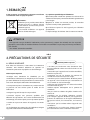
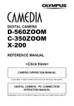
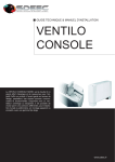
OTE
ed on the energy label is based
n of installing the un-extended
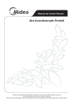
Remarque
ut adaptor
Aindiquée
& Bsur(The
and
La notation
l’étiquetteduct
d’énergie est
basée
sur les conditions de test de l’installation avec conduit
sted ind’évacuation
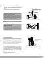
the accessories
de l’air non étendu et sanschart
l’adaptateur.
Voir l’image de droite.
al). See the right figure.
3
1.Remarque
Il faut respecter les informations suivantes en utilisant
ce climatiseur dans les pays européens :
éliminations :
N’éliminez pas ce produit comme déchet
ménager non trié. La collecte séparée
de tels déchets est nécessaire pour un
traitement spécial.
Il est interdit d’éliminer cet appareil
dans les déchets ménagers.
Il y a plusieurs possibilités pour l’élimination :
A) La municipalité a établi des systèmes de collecte où les
déchets électroniques peuvent être éliminés gratuitement
pour l’usager.
B) Quand on achète un nouveau produit, le revendeur
reprend le vieux produit gratuitement.
C) Le fabricant reprend le vieil appareil pour l’éliminer
gratuitement.
Le dépôt sauvage des déchets dans la nature est interdit.
Attention
• Cet appareil n’est pas destiné à l’utilisation par des personnes (y compris des enfants) avec des capacités
physiques, sensorielles ou mentales réduites sauf si elles sont surveillées ou par une personne responsable de
leur sécurité.
• Les enfants doivent être surveillés.
2.PRéCAUTIONS DE SéCURITé
2.1 Règles de sécurité
Pour éviter des blessures, il faut suivre les instructions
suivantes. Une mauvaise utilisation en ignorant ces
instructions peut causer un préjudice ou des dommages.
Faites toujours ce qui suit
• Protégez votre climatiseur de l’humidité, par ex.
condensation, éclaboussure, etc. Ne placez pas ou ne rangez
pas votre climatiseur là où il pourrait être en contact avec de
l’eau ou un autre liquide. Débranchez immédiatement.
• Transportez toujours le climatiseur en position verticale
et placez-le sur une surface plane et stable lors de
l’utilisation.
• Eteignez l’appareil lorsqu’il n’est pas utilisé.
• Contactez toujours une personne qualifiée pour
effectuer des réparations. Si le cordon d’alimentation est
endommagé, il doit être réparé par un réparateur qualifié.
• Gardez un espace tout autour de l’appareil, d’au moins
30 cm.
• Si le climatiseur est renversé lors de l’utilisation, éteignez
l’appareil et débranchez-le immédiatement.
4
Ne faites jamais ce qui suit
• Ne faites pas fonctionner votre climatiseur dans
une pièce humide comme une salle de bains ou une
buanderie.
• Ne touchez pas l’appareil avec les mains mouillées,
humides ou pieds nus.
• N’appuyez pas sur les boutons du panneau de
contrôle avec autre chose que vos doigts.
• Ne retirez pas les couvercles fixes. N’utilisez jamais
cet appareil s’il ne fonctionne pas correctement ou
s’il est tombé ou a été endommagé.
• Ne forcez pas le démarrage ou l’arrêt en branchant
ou débranchant la prise.
• Utilisez toujours l’interrupteur sur le panneau de
commande.
• Ne pas couvrir ou obstruer les grilles d’entrée ou de
sortie d’air.
• N’utilisez pas de produits chimiques corrosifs
pour nettoyer l’appareil. N’utilisez pas l’appareil en
présence de substances ou de vapeurs inflammables
tels que de l’alcool, des insecticides, de l’essence,
etc.
• Ne laissez pas les enfants utiliser l’appareil sans
surveillance.
• N’utilisez pas ce produit pour d’autres fonctions
que celles décrites dans ce manuel d’instruction.
Economie d’énergie
• Utilisez l’appareil dans une pièce de taille adaptée.
• Placez l’unité de façon à ne pas gêner la circulation de l’air.
• Fermez les stores / rideaux au moment le plus ensoleillé de la journée.
• Gardez les filtres propres.
• Gardez les portes et les fenêtres fermées pour garder l’air frais à l’intérieur et l’air chaud à l’extérieur.
2.2 Conditions de fonctionnement
Le climatiseur doit être utilisé dans l’intervalle de température indiqué ci-dessous :
Mode
Température de la pièce
Refroidissement (cool)
17°C~35°C
Déshumidification (dry)
13°C~35°C
Outils proposés pour installation du kit sur fenêtre :
1. Tournevis (cruciforme de taille moyenne)
2. Mètre-ruban ou règle
3. Couteau ou ciseaux
4. Scie (Dans le cas où le kit de fenêtre doit être réduit de taille.)
AVERTISSEMENT Pour votre sécurité
• Ne pas entreposer ni utiliser d’essence ou d’autres vapeurs et liquides inflammables à proximité de cet appareil.
• Éviter tout risque d’incendie ou de choc électrique. Ne pas utiliser de rallonge ou d’adaptateur.
AVERTISSEMENT Informations électriques
• Assurez-vous que l’alimentation électrique est
conforme. Cette information peut être trouvée sur la
plaque signalétique qui se trouve sur le côté du boîtier
et derrière la grille.
• Assurez-vous que le climatiseur est correctement mis
à la terre.
• Votre climatiseur doit être branché dans une prise
murale correctement mise à la terre. Si la prise murale
que vous comptez utiliser n’est pas correctement mise à
la terre ou protégée par un disjoncteur, demandez à un
électricien qualifié d’installer la prise appropriée.
• S’assurer que la prise est accessible après l’installation
de l’unité.
5
a
properly
grounded
wall
receptacle.
the
wall
receptacle
you
intend
Your
air
conditioner
must
be
used
hazards.
on the
plate, which
is used
located
the sidegrounded
of the cabinet
and behindIfIf
inaon
aproperly
properly
grounded
wallreceptacle.
receptacle.
Ifthe
thegrille.
wallreceptacle
receptacleyou
youintend
intend
Your
airserial
conditioner
mustbe
be
usedinin
wall
the
wall
Your
air
conditioner
must
totouse
isis
not
adequately
grounded
oror
protected
by
aatime
delay
fuse
ororcircuit
breaker,
have
aaqualified
in
a
properly
grounded
wall
receptacle.
If
the
wall
receptacle
you
intend
Your
air
conditioner
must
be
used
use
not
adequately
grounded
protected
by
time
delay
fuse
circuit
breaker,
have
qualified
inor
a protected
properly
grounded
receptacle.
Iffire
thehazards,
wall receptacle
you
intendis
Your
air
conditioner
must be
used
Beuse
sure
the
air
conditioner
is properly
grounded.
minimize
shock
and
proper
to
use
isnot
notadequately
adequately
grounded
or
protected
byTo
timewall
delay
fuseor
or
circuit
breaker,
haveaagrounding
qualified
to
is
grounded
by
aatime
delay
fuse
circuit
breaker,
have
qualified
electrician
the
proper
receptacle.
to
use isis not
notinstall
adequately
grounded
or protected
protected
by aa time
time delay
delay
fuse or
or circuit
circuit
breaker,
have
qualified
electrician
install
the
proper
receptacle.
to
use
adequately
grounded
or
fuse
have
aa qualified
important.
The
power
cord
is
equipped
with a by
three-prong
grounding
plug
forbreaker,
protection
against
shock
electrician
install
theproper
proper
receptacle.
electrician
install
the
receptacle.
Ensure
the
receptacle
is
accessible
after
the
unit
installation.
electrician
install
the
proper
receptacle.
Ensure
the
receptacle
is
accessible
after
the
unit
installation.
electrician
install
the
proper
receptacle.
hazards.
Ensurethe
thereceptacle
receptacleisisaccessible
accessibleafter
afterthe
theunit
unitinstallation.
installation.
Ensure
Ensure
theconditioner
receptaclemust
accessible
after
the unit
unit installation.
installation.
Ensure
the
receptacle
isis accessible
the
in
a properly
grounded
wall receptacle. If the wall receptacle you intend
Your air
be used after
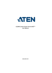
Accessories
Accessories
Accessories
Accessories
to
use
is
not
adequately
grounded
or
protected
by
a
time
delay
fuse or circuit breaker, have a qualified
Accessories
Accessories
PARTS
NAME
:
QUANTITY
:
PARTS
:
electrician
install
PARTS
NAME
QUANTITY
PARTS
PARTSNAME
NAME:::
QUANTITY:::
PARTS
PARTS
QUANTITY
PARTS
::: the proper receptacle.
PARTS
NAME ::
QUANTITY ::
PARTS
Ensure
the receptacle
is accessible after the
unit installation.
PARTS
NAME
QUANTITY
PARTS
::
Exhaust
hose
and
Apaptor
I Iand
Adaptor
BB
11set
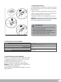
3.1 accessoires
Exhaust
hose
and
Apaptor
and
Adaptor
set
Exhausthose
hoseand
andApaptor
ApaptorI Iand
andAdaptor
AdaptorBB
set
Exhaust
11set
Accessories
Exhaust
hose
and
Apaptor
I
and
Adaptor
B
1
set
(flat
mouth
or
round
mouth
:depending
on
models)
Exhaust
hose
and
Apaptor
I
and
Adaptor
B
1
set
(flat
mouth
or
round
mouth
:depending
on
models)
(flatla
mouth
roundmouth
mouth:depending
:dependingon
onmodels)
models)
mouth
ororround
Pièce
Nom (flat
de
pièce
Quantité
or
Window
Kit
and
bolt
(flat
mouth
orSlider
round
mouth
:depending
onmodels)
models)
or:
Window
Slider
Kit
and
bolt
or
PARTS
NAME
:
QUANTITY :
PARTS
(flat
mouth
or
round
mouth
:depending
on
WindowSlider
SliderKit
Kitand
andbolt
bolt
Window
or
Window
Slider(1.4m)
Kit and
and bolt
bolt
or
Window
Slider
Kit
Tuyau
d’évacuation
Exhaust hose
Apaptor
I and Adaptor B
11 ensemble
set
avec adaptateur
etand
bouche
plate
3. identification des pièces
or
11pc
pc
pc
11pc
1
pc
1 pc
1 pièce
C) C)
SET TEMPERATURE(
SET TEMPERATURE(
ON/OFF
MODE
ON/OFF FAN SPEED FAN SPEED
ON ON
TIMERTIMER
SWING
SWING
ECONOMY
ECONOMY
ON/OFF FAN SPEED
MODE
TIMER ON ON/OFF FAN SPEED
SWING ECONOMY MODE
ECONOMY TIMER ON
OFF OFF
TIMERTIMER
ION IONRESET RESET
LOCK LOCK
SWING ECONOMY TIMER ON
TIMER OFF
ION
RESET LOCK SWING
ECONOMY TIMER ON
C) FAN
AUTOAUTOSET TEMPERATURE(FAN
SET TEMPERATURE( C)
HIGH HIGH
COOLCOOL
FAN
C)
SET TEMPERATURE(
AUTO
MED MED
FAN
AUTO DRY DRY
HIGH
COOL
C)
TEMPERATURE(
SETLOW
HIGH LOW
COOL HEAT HEAT
FAN
AUTO
MED
DRY
MED
DRY
HIGH FAN
COOL
AUTO LOW
HEAT
LOW
HEAT
MED HIGH
DRY
TEMPTEMP
COOL
LOW MED
HEAT DRY
TEMP
LOW
HEAT
TEMP
TEMP
ON/OFF
MODEMODE ON/OFF
FAN SPEED
FAN SPEEDTEMP
SWING
MODE
TIMER
LED OFF
LED
LOCK FOLLOW
RESETFOLLOW
TURBO
TURBO
ME ME
DISPLAY
DISPLAY
TIMER OFF
ION
RESET LOCK
FOLLOW
LED
TURBO
FOLLOW
TIMER OFF
LED ME
DISPLAYION
RESET LOCK
ME
DISPLAY TURBO FOLLOW
LED
ME
DISPLAY TURBO
FOLLOW
LED
ME
DISPLAY TURBO
FAN
HIGH
MED
LOW
TIMER ON
TIMER OFF
SET TEMPERATURE( C)
AUTO
COOL
DRY
HEAT
TEMP
ECONOMY
ON/OFF FAN SPEED
RESET LOCK
FOLLOW
LED
ME
DISPLAY TURBO
ION
SWING
MODE
PARTS
PARTS
(flat mouth or round mouth :depending on models)
Wall
Exhaust
Adaptor
A(
? ))
Wall
Exhaust
Adaptor
A(
Window
Slider
KitAdaptor
and boltA(
WallExhaust
Exhaust
Adaptor
A(??
? ))
Wall
Wall Exhaust
ExhaustAdaptor
AdaptorA(
A( ? )
Wall
Adaptateur
A d’évacuation
murale ? )
11pc
Adaptor
B(round
mouth)
( ? ))
pc
Adaptor
B(round
mouth)
pc
11pc
AdaptorB(round
B(roundmouth)
mouth)(((??
? ))
Adaptor
1
pc
Adaptateur
B
(bouche
ronde)
Adaptor
B(round
mouth)
(
?
)
1 pièce
1
pc
1
pc
Adaptor
B(round
mouth)A(
( ?? ))
Wall Exhaust
Adaptor
Expansion
Plug
and
wooden
screw(?
)
4/4/pc
Expansion
Plug
and
wooden
screw(?
Expansion
Plugand
andwooden
wooden screw(?
screw(?)))
Cheville etExpansion
vis à bois Plug
4/pc
pcpièces
4pc
4/
Expansion
Plug
and
wooden
screw(?
)
4/
pc
Expansion
Plug
and
wooden
screw(?
)
4/
pc
Foam
seal
1 pc
3/pc
Adaptor
B(round mouth)( ? )
Foam
seal
3/pc
Foam
seal
Foam
seal
3/pc
Joint en mousse
3/pc
3 pièces
Foam seal
seal
3/pc
Foam
3/pc
Remote
Controller
and
Battery
Télécommande
et pile
(uniquement
pour
modèles
à )
Remote
Controller
and
Battery
1pc
Expansion
Plug and
wooden
screw(?
4/ pc
Remote
Controller
and
Battery
Remote
Controller
and
Battery
1pc
(For
remote
control
models
only)
1pc1 pièce
1pc
télécommande)
(For
remote
control
models
only)
Remote
Controller
and
Battery
(Forremote
remote
control
models
only)
(For
control
models
only)
Remote
Controller
and
Battery
1pc
1pc
(For
remote
control models
models only)
only)
Foam
sealcontrol
3/pc
(For
remote
hose
and
drain
hose
adaptor(
))
IDENTIFICATION
OF PARTS
1pc
Tuyau de Drain
purge
et
adaptateur
1 pièce
Drain
hose
and
drain
hose
adaptor(
1pc
Drainhose
hoseand
anddrain
drainhose
hoseadaptor(
adaptor( ))
Drain
1pc
1pc
Drain
hose
and
drain
hose
adaptor(
)
1pc
Drain
hose Controller
and drain and
hoseBattery
adaptor( )
Remote
1pc
1pc
(For
remote control models only)
NOTE:
Optional
parts(
),
some
models
without.
NAMES
NOTE:
Optional
parts(
),
some
models
without.
2
NOTE:Optional
Optionalparts(
parts( ),),some
somemodels
modelswithout.
without.
1
NOTE:
NOTE:
Optional
parts(
),
some
models
without.
Check
all
the
accessories
included
ininthe
and
the
instructions
for
NOTE:
Optional
parts( are
),
models
without.
Check
all
the
accessories
aresome
included
thepackage
package
andplease
pleaserefer
refer:to
to
theinstallation
installation
instructions
for
F
Check
allthe
the
accessories
are
included
the
package
and
please
refer
to
the
installation
instructions
for
Check
all
accessories
are
included
ininthe
package
and
please
refer
to
the
installation
instructions
for
Vérifiez
que
tous
les accessoires
sont
compris
dans
Toutes
les )illustrations
de ce
manuel sont à
REMARQUE
Drain
hose
and
drainrefer
hose
adaptor(
their
usage.
1pc
their
usage.
Check
all
the
accessories
are
included
in
the
package
and
please
to
the
installation
instructions
for
theirusage.
usage.
their
4
Check
all the
in thed’installation
package and please
refer
to
the
installation
instructions
for
l’emballage
et accessories
référez-vousare
auxincluded
instructions
des fins d’explication uniquement. Votre climatiseur peut
theirleur
usage.
All
the
illustrations
ininthis
manual
are
for
explanation
purpose
only.
Your
air
conditioner
NOTE:
their
usage.
All
the
illustrations
this
manual
are
for
explanation
purpose
only.
Your
air
conditioner
NOTE:
pour
utilisation.
être légèrement
Laair
forme
réelle prévaudra.
All
the
illustrations
in
this
manual
are
for
explanation
purposedifférent.
only.Your
Your
air
conditioner
NOTE:
All
the
illustrations
in
this
manual
are
for
explanation
purpose
only.
conditioner
NOTE:
may
be
slightly
different.
The
actual
shape
shall
prevail.
may
be
slightly
different.
The
actual
shape
shall
prevail.
All
the
illustrations
in
this
manual
are
for
explanation
purpose
only.
Your
air
conditioner
NOTE:
NOTE:
Optional
parts(
),
some
models
without.
may
be
slightlydifferent.
different.
Theactual
actual
shape
shallprevail.
prevail.
may
be
slightly
The
shape
shall
All
the
illustrations
in
this
manual
are
for
explanation
purpose
only.
Your
air
conditioner
NOTE:
1 Operation
maypanel
be slightly
slightly different.
different. The
The actual
actual shape
shape shall
shall
prevail.
panel
1
Operation
panel
1 Operation
may
be
prevail.
IDENTIFICATION
OF PARTS
Operation
panel
1
Check
all
the accessories
are included
in the package
and
please refer to the installation
instructions for
Operation panel
panel
1 Operation
Horizontal
louver blade
21
44
Horizontal
louver
blade
2
their
usage.
Horizontal
louver blade
blade
2
Horizontal
louver
(swing
automatically)
2
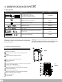
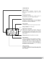
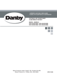
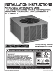
3.2 Identification des pièces
44
ION
ARTS
ARTS
ARTS
ARTS
ARTS
ARTS
Kit de glissière de fenêtre et boulon
(swing
Horizontal
louver blade
(swing automatically)
automatically)
(swing automatically)
2 Horizontal
NAMES
Alllouver
the blade
illustrations in this manual are for explanation
Your air conditioner
NOTE:
(swing
44 OF PARTS
2 purpose only.
Caster automatically)
automatically)
3 (swing
1
Caster
3
Caster may be slightly different. The actual shape shall prevail.
3 Caster
3
NOMS
DES PIèCES
Caster
3
Carrying handle
Front
4
3 Caster
handle
4
Carrying
handle
Fig.1
4 Carrying
Carrying
handle
(both
sides)
4
Operation
panel
1 Carrying
(both
sides)
4
handle
4
(both sides)
sides)
(both
handle
4 Carrying
AVANT
2
Operation
panel
1
sides)
(both
Operation
panel
1 P
anneau
commande
(both
sides)de
2 Horizontal louver blade
(swing
automatically)
Horizontal
louver
blade
2
ame de volet
louverhorizontale
blade
2 LHorizontal
3
3
3
4
(swing
(swing automatically)
automatically)
4
3
(oscille automatiquement)
Fig.1
RCaster
oulette
Caster
Caster
PCarrying
oignée handle
de transport (des deux côtés)
(both
sides)
Carrying
handle
4
handle
4 Carrying
(both
sides)
Upper sides)
air filter
5 (both
6
Upper air
air
filter
5
Upper
filter
5 F(Behind
the
grille)
Upperàair
filter
5
iltre
air
supérieur (Derrière la grille)
(Behind
the
grille)
(Behind
the
grille)
Upper
air
filter
5
the
grille)
Upper air
air
filter
6 (Behind
5
Upper
intake
(Behind
the
grille)
Upper
air
intake
6
Upper
airthe
intake
6
grille)
rise d'air
supérieure
Upper
air
intake
6 P(Behind
Upper air
6
air intake
intake
6
7 Upper
Air outlet
7
Air
outlet
SAir
ortie
7
outletd'air
7 Air
outlet
Air
outlet
outlet (only for Pump
87
7 TDrain
Air
outlet
Drain
outlet
(only
for(uniquement
Pump
8
rou
de
vidange
pour modèle à pompe à chaleur)
Drain
outlet
(only
8 Drain
heating
model)
outlet
(only for
for Pump
Pump
8
heating
model)
Drain
outlet
(only
for
Pump
heating
model)
8
heating
model)
outlet
(only
for
Pump
85 Drain
Upper
air
filter
Power
cord
outlet d'alimentation
model)
rise du
cordon
9 Pheating
Power
cord
heating
model)
9
Power
cord
outlet
(Behind
the outlet
grille)
9
Power
outlet
Upper
air
95
Uppercord
air filter
filter
5 Power
cord
outlet
9
10
Power
cord
buckle
(Used d'alimentation
(Behind
grille)
rochets
pour
outlet
Upper airthe
intake
96 CPower
(Behind
the
grille) cordon
10
cord
buckle
(Used
10 Power
cord
buckle
(Used
only
when
storing
unit)
10
Power
cord
bucklethe
(Used
Upper
air
intake
6
only
when
storing
the
unit)
Upper
air
intake
6 (Utilisée
uniquement
10
Power
cord
buckle
(Used
only when
when
storing
the
unit)lors du rangement de l'appareil)
only
storing
the
unit)
10
cord
buckle
(Used
Air
outlet
Bottom
tray
drain
outlet
117 Power
only
when
storing
the
unit)
Bottom
tray
drain
outlet
11
only
when
storing
the
unit)
Bottom
tray
drain
outlet
117 VBottom
tray
drain
outlet
11
idange
du
bac
inférieur
Air outlet
outlet
Air
tray
drain
Drain
outlet
(onlyoutlet
for
Pump
1187 Bottom
Power
plug
socket
(Use
12
Bottom
tray
drain
outlet
11
Power
plug
socket
(Use
12
heating
model)
plug
socket
(Use
12
only
when
storing
unit)
Power
plug
socket
(Use
Drain
outlet
(only
for
Pump
128
rise
pour
fiche
d'alimentation
8 PPower
Drain
outlet
(only the
for
Pump
only
when
storing
the
unit)
Power
plug
socket
(Use
only
when
storing
the
unit)
12
only
when
storing
unit)
heating
model)
Power
plug
socket
(Use
12
heating
model)
Power
cord
outletthe
Lower
air
filter
139 (Utilisée
only
when
storing
the
unit)
uniquement
Lower
air
filter
13 only
when
storing
the unit)lors du rangement de l’appareil)
Lower
air
filter
13
the
grille)
Lower
filter
139 (Behind
Power
cord
outlet
Powerair
cord
outlet
the
grille)
9 (Behind
Lower
air
filter
(Behind
the
grille)
13
(Behind
the
grille)
10
Power
cord
buckle
(Used
Lower
air
filter
13
iltre àair
air
inférieur
(Derrière la grille)
intake
14 FLower
(Behind
grille)
Lower
airthe
intake
only when
storing
the unit)
14
(Behind
grille)
intake
14
10 Lower
Power
cord
buckle
Lower
airthe
intake
10
14
Powerair
cord
buckle (Used
(Used
Lower
air
intake
14
only
when
storing
the
unit)
P
rise
d'air
inférieure
only
when
storing
the unit)
1511 Drain
Bottom
drain outlet
Lower
air tray
intake
outlet
14
15
Drain outlet
15
outlet
1511 Drain
Drain
outlet
Bottom
tray
drain
Bottom
tray
drain outlet
outlet
11 TDrain
15
outlet
rou
de
vidange
Power
plug
socket
(Use
12 Drain outlet
15
only when
unit)
Power
plugstoring
socketthe
(Use
12
plug
socket
(Use
12 Power
when
storing
Lower
air filter
only
when
storing the
the unit)
unit)
13 only
(Behindair
the grille)
13
Lower air filter
filter
13 Lower
(Behind
grille)
(Behindairthe
the
grille)
intake
14 Lower
Lower air
air intake
intake
14
14 Lower
15 Drain outlet
1
2
3
R4
3
5
Fig.1
Fig.2
arrière
6
15
Rear
7
5
6
7
8
9
14
8
13
9
10
15
11
14
13
12
Fig.2
1
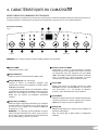
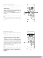
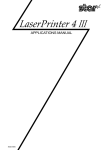
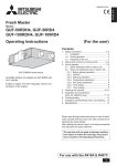
4. caractéristiques du climatiseur
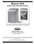
MODE D’EMPLOI DES COMMANDES éLECTRONIQUES
Avant de commencer, familiarisez-vous bien avec le panneau de commande et la télécommande et toutes leurs fonctions.
L’appareil peut être commandé par le panneau de commande de l’appareil seul ou avec la télécommande.
Panneau de commande
Fig.3
AIR CONDITIONER FEATURES
8 AIR CONDITIONER
FEATURES
10
9
AIR CONDITIONER FEATURES
ELECTRONIC CONTROL OPERATING INSTRUCTIONS
ELECTRONIC CONTROL OPERATING INSTRUCTIONS
Before you begin, thoroughly familiarize yourself with the control panel and remote controller
AIR
CONDITIONER
FEATURES
ELECTRONIC
CONTROL
OPERATING
INSTRUCTIONS
CONDITIONER
FEATURES
Before
you
begin,
yourself
withAIR
the control
panel and remote
controller
and
all its functions,
then
follow
thethoroughly
symbol forfamiliarize
the functions
you desire.
and
all
its
functions,
then
follow
the
symbol
for
the
functions
you
desire.
Before
you
begin,
thoroughlybyfamiliarize
yourselfpanel
with the
control
panel
remote
controller.
The
unit
can
be controlled
the unit control
alone
or with
theand
remote
controller
ELECTRONIC
CONTROL
OPERATING
INSTRUCTIONS
AIR
CONDITIONER
FEATURES
ELECTRONIC
CONTROL
OPERATING
INSTRUCTIONS
The
unit
controlled
by
the
unit
control
panel
alone
or with
the remoteFEATURES
controller .
and
all This
its functions,
then
follow
the
symbol
for
the
functions
you
desire.
AIR
CONDITIONER
NOTE:
manual
doescan
notbe
include
Remote
Controller
Operations,
see
the
<<Remote
The unit
can
beNOTE:
controlled
by
the
unit
control
panel
alone
or
with
the
remote
controller
.theFEATURES
This
manual
does
not
include
Remote
Controller
Operations,
see
<<Remote
Before
you
begin,
thoroughly
familiarize
yourself
with
the
control
panel
and
remote
controller
Controller
Instruction>>
packed
with
the
unit
for
details.
Before you begin, thoroughly familiarize yourself withAIR
the control
panel
and
remote
controller
CONDITIONER
ELECTRONIC
CONTROL
OPERATING
Controller
Instruction>>
packed
with
the for
unit
for
details.
and
all its
functions,
then
the
symbol
forINSTRUCTIONS
the
functions
you
desire.
NOTE:
This
manual
does
not
include
Remote
Controller
Operations,
seeyou
thedesire.
<<Remote
and
all
its follow
functions,
then
follow
the
symbol
the
functions
ELECTRONIC
CONTROL
OPERATING
INSTRUCTIONS
The unit
can
be
controlled
by
the
unit
control
panel
alone
or panel
with
the
remote
controller
.
Controller
Instruction>>
packed
with
the
unit
for
details.
The
unit
can
be
controlled
by
the
unit
control
alone
or with
the
remote
controller
OPERATION
PANEL
OF
THE
AIR
CONDITIONER
Before
you
begin,
thoroughly
familiarize
yourself
with
the
control
panel
and
remote
controller
ELECTRONIC
CONTROL
OPERATING
INSTRUCTIONS
Before
you
begin,
thoroughly
familiarize
yourself
with
the
control
panel
and
remote
controller.
OPERATION
PANEL
OF
THE
AIR
CONDITIONER
NOTE:
This
manual
does
not
include
Remote
Controller
Operations,
see
thedesire.
<<Remote
and all its
functions,
then
follow
the symbol
for include
the
functions
you
desire.
NOTE:
This
manual
does
not
Remote
Controller
Operations,
see the <<Remote
and
all
its
functions,
then
follow
the
symbol
for
the
functions
you
9
Before
you
begin,
thoroughly
yourself
with the
the control
panel
and remote
controller
(Optional)
8familiarize
10
OPERATION
PANEL
OFpacked
THE
AIR
CONDITIONER
Controller
Instruction>>
with
the
unit
for
details.
The unit can
be
controlled
by
unit
control
panel
or panel
with
remote
controller
.
Controller
Instruction>>
packed
with
the
unit
for
details.
9alone
The
unit
bethe
controlled
by (Optional)
the
control
alone
or with
the remote
controller .
and
all
itscan
functions,
then follow
the unit
symbol
for8 the
functions
desire.
10 you
NOTE: This manual
does
not
include
Remote
Controller
Operations,
see
the
<<Remote
9 not
NOTE:
This
does
Controller
Operations,
the <<Remote
The unit
canmanual
be(Optional)
controlled
by
the unitRemote
control
panel alone
or with the see
remote
controller .
8include
10
OPERATION
PANEL
OF
THE
AIR
Controller Instruction>>
packed
withCONDITIONER
the THE
unit
for
details.
OPERATION
PANEL
OF
AIR
CONDITIONER
Controller
with
the unit Controller
for details.Operations, see the <<Remote
NOTE: ThisInstruction>>
manual does packed
not include
Remote
9 packed
Controller Instruction>>
with9the
(Optional)
8 (Optional)
10 unit
8 for details.
10
OPERATION PANEL
OF THE
AIR CONDITIONER
OPERATION
PANEL
OF THE AIR CONDITIONER
7
6
59 8 AIR CONDITIONER
49 10
OPERATION PANEL
(Optional) OF THE
(Optional)
9
En option
(Optional)
7
6
5
4
4
8
8
10
4
3
1
ION en option
10
3
2
2
1
7 modèles
6 le bouton
5
(Optional) : Sur certains
(ION is Optional)
REMARQUE
SLEEP4 remplace
le4 bouton 3ECO.
2
1
(ION
7
6 (Optional) 5
4
4
3
2 is Optional)
1 Fig.3
(Optional)
(ION is Optional)
NOTE:
On some models SLEEP button is instead of ECO button.
Fig.3
button
ECO button.
7
6NOTE:
4 SLEEP
4 4 is instead
3 of 4
2
1 Fig.32
7 On5 some6 models
5
3
1
(Optional)
(Optional)SLEEP button is instead of ECO (ION
NOTE:
On some models
button.
is Optional) (ION is Optional)
button
54 MODE select
7
6
5
4
3
2
1 Fig.32
7
6
5
4Selects the
4 B
3de sélection
1 Fig.3
select
button
POWER
outon
POWER
MODE
outon
appropriate
operating
mode.de MODE
1 B
5
button
(Optional)
NOTE:
On
someNOTE:
models
SLEEP
button
is
instead
of
ECO
button.
(ION
is
Optional)
On
some
models
SLEEP
button
is
instead
of
ECO
button.
(Optional)
(ION
is
Optional)
Selects
the
appropriate
operating
1
POWER
button
Each
time
you
press
the
button,
a
mode
7
6
5
4
4
3
2
1 mode.
MODE
select
button
5
Power switch on/off.
31 I nterrupteur
marche
/switch
arrêton/off.
33
Sélectionne
le
mode
de aFig.3
fonctionnement
souhaité.
Fig.3
Each
time
yougoes
press
the button,
mode
(Optional)
Selects
theinappropriate
operating
mode.
is
selected
a sequence
from
(ION
is that
Optional)
POWER button
Power
NOTE: On someNOTE:
modelsOn
SLEEP
is SLEEP
instead button
of ECO
is
selected
in HEAT(cooling
a sequence
that
goes
from
somebutton
models
isbutton.
instead
of ECO
button.
Each
time
you
press
the
button,
a
mode
Chaque
fois
que
vous
appuyez
sur
la
touche,
un mode
COOL,
DRY,
FAN
and
2 SLEEP/ECO
MODE
select
button
5 AUTO,
Power switchbutton
on/off.
MODE
select
button
Fig.3
5
AUTO,
COOL,
DRY,
FAN
and HEAT(cooling
21 SLEEP/ECO
button
isisselected
aECO
sequence
that
goes
from
only
models
without).
The
mode
indicator
Selects
the in
appropriate
operating
mode.
1 Used
NOTE:
On
some
models SLEEP button
instead
of
button.
POWER
button
Selects
the
appropriate
operating
mode.
POWER
button
to initiate
the
SLEEP/ECO
operation.
est
sélectionné
dans
une
séquence
qui
va
de
AUTO,
only
models
without).
Thebutton,
mode aindicator
AUTO,
COOL,
DRY,
and
HEAT(cooling
SLEEP/ECO
outonswitch
SLEEP/ECO
2 B
light
illuminates
under
the
different
mode
button
time
you press
the
button,
a mode
Used
toswitch
initiateon/off.
the SLEEP/ECO operation.
EachFAN
time
you
press
the
mode
MODE
select
button
Power
on/off.
5 Each
Power
COOL,
DRY,
FAN
et
HEAT
(refroidissement
seulement
MODE
select
button
5
button
light
illuminates
under
the
different
mode
31 FAN/ION
(ION
is
optional)
only
models
without).
The
mode
indicator
settings.
is selected
a sequence
that
goes
from that goes from
is
selected
in
a
sequence
Used
to initiate
the
SLEEP/ECO
operation.
the in
appropriate
operating
mode.
POWER
button
32 P
Control
ermet
lancer
le tofonctionnement
/ ECOSelects
Selects
the
appropriate
operating
mode.indicateur de mode
FAN/ION
button
POWER
button
31button
optional)
settings.
the de
fan speed.
Press
select
the
fan (ION isSLEEP
MODE
select
light illuminates
under
the
different
mode
pour
ce
modèle).
Le
AUTO,
COOL,
DRY,
FAN
and
HEAT(cooling
SLEEP/ECO
AUTO,
COOL,
DRY,
FAN
and voyant
HEAT(cooling
2on/off.
SLEEP/ECO
button
Each
time
you5press
the
button,
abutton
mode
6
TIMER
button
Power
switch
Each
time
you
press
theoperating
button,
a mode.
mode
Control
the
fan
speed.
Press
to
select
the
fan
FAN/ION
button
3 speed
(ION
is
optional)
Selects
the
appropriate
in four steps-LOW,
MED,switch
HIbutton
and AUTO.
1 POWER
Power
on/off.
settings.
only
models
without).
The
mode
indicator
only
models
without).
The
mode
indicator
is selected
in 6
a the
sequence
that
goes
from
s’allume
dans
les
différents
paramètres
du mode.
Used
to
the
SLEEP/ECO
operation.
TIMER
button
Used
to
initiate
the
SLEEP/ECO
operation.
is
selected
in
a
sequence
that goes
from
Used
to initiate
AUTO
ON
start
time
and
speed
in
four
steps-LOW,
MED,
HI
and
AUTO.
Control
theinitiate
fanindicator
speed.
Press
to
select
the
fan
Each
time
you
press
the
button,
a
mode
The
fan
speed
light
illuminates
under
light
illuminates
under
the
different
mode
Power switch on/off.
light
illuminates
under
the and
different
mode
AUTO,
COOL,
DRY,
FAN
and HEAT(cooling
2 SLEEP/ECO2button
6 AUTO
Used
toCOOL,
initiate
the
AUTO
ON HEAT(cooling
start
time
and
TIMER
button
AUTO,
DRY,
FAN
OFF
stop
time
program,
in
conjuction
SLEEP/ECO
button
The
fan
speed
indicator
light
illuminates
under
speed
infan
four
steps-LOW,
MED,
HI
and
AUTO.
is
selected
in
a
sequence
that
goes
from
settings
except
AUTO
speed.
When
FAN/ION
button
different
outon
FAN/ION
(ION
non
disponible)
3 B
(ION
is
optional)
settings.
3 FAN/ION button (ION is optional)
settings.
only
models
The
mode
indicator
AUTO
OFF
time
program,
inindicator
conjuction
Used
to
initiate
SLEEP/ECO
operation.
only
models
without).
The
mode
Usedthe
to initiate
the
AUTO
ONstop
start
time
and
&without).
buttons.
The
timer
on/off
different
settings
except
AUTO
speed.
When with
The
fan
speed
light
illuminates
under
AUTO,
COOL,
DRY,
FAN
and
HEAT(cooling
select
AUTO
fanindicator
speed,
all
the
fan
indicator
lights
2 the
SLEEP/ECO
button
Used
to
initiate
the
SLEEP/ECO
Control
the
fan
speed.
Press
tofan
select
the
fan
Control
the
fan
speed.
Press
to select
the operation.
fan
light
illuminates
under
the
different
mode
with
the
&
buttons.
timer
on/off
6
3 C
turn
ontrôle
la
vitesse
du
ventilateur.
Appuyez
pour
light
illuminates
under
the The
different
mode
AUTO
OFF
stop
time
program,
in
conjuction
TIMER
button
B
outon
TIMER
indicator
light
illuminates
under
the
timer
6
select
AUTO
fan
speed,
all
the
fan
indicator
lights
TIMER
button
different
except
AUTO
speed.
When
only
models
without).
The
mode
indicator
dark.
speed
in fan
foursettings
steps-LOW,
MED,
HIoptional)
and AUTO.
speed
in
four
steps-LOW,
MED,
HI
and
AUTO.
button
3 FAN/ION
Used
to
initiate
the
SLEEP/ECO
operation.
(ION
is
settings.
FAN/ION
button
3button
indicator
light
illuminates
under
themode
timerand
(ION is optional)
settings.
with
the
& the
buttons.
The
timer
on/off
on/off
settings.
turn
dark.
Used
to
initiate
AUTO
ON
start
time
and
select
AUTO
fan
speed,
all
the
fan
indicator
lights
light
illuminates
under
the
different
NOTE:
Press
this
for
3
seconds
to
initiate
Used
to
initiate
the
AUTO
ON
start
time
sélectionner
la
vitesse
du
ventilateur
en
quatre
étapes
The
fan
speed
indicator
light
illuminates
under
The
fan
speed
indicator
light
illuminates
under
Control the fan speed.Control
Press the
to select
the fanPress to select the fan
33
Utilisé
pourin
initier
le programme d’heure de début
fanbutton
speed.
on/off
settings.
indicator
light
illuminates
under
the
timer
FAN/ION
NOTE:
Press
this
button
forwillAUTO
3 seconds
to initiate
3 generator
AUTO
OFF
stop
time
program,
conjuction
is optional)
turn
dark.
ION
feature.The
ion
is HI
energized
and(ION
TIMER
button
AUTO
OFF
stop
time
program, in conjuction
different
fan
except
AUTO
speed.
When
button
76 SWING
different
fan
settings
except
speed.
When
6 settings.
speed
inMED,
foursettings
steps-LOW,
MED,
and AUTO.
TIMER
button
LOW,
HI
et
AUTO.
speed
in
four
steps-LOW,
MED,
HI
and
AUTO.
on/off
settings.
AUTO
ON
et
d’heure
d’arrêt
AUTO
OFF, en conjonction
ION
feature.The
ion
generator
is
energized
and
will
Control
the
fan
speed.
Press
to
select
the
fan
with
the
&
buttons.
The
timer
on/off
NOTE:
Press
this
button
for
3
seconds
to
initiate
help
to
remove
pollen
and
impur
ities
from
the
air,
and
with
the
&
buttons.
The
on/off
SWING
button
7 the
select
speed,
all the
fan fan
indicator
lights
Used totoinitiate
AUTO
ON feature
start
and
select
AUTO
speed,
all the
fan indicator
lights(Applicable
the models
with
auto
swing
only)
The fanAUTO
speedfanindicator
light
illuminates
under
Used
to initiate
thetime
AUTO
ON timer
start time
and
6
TIMER
button
The
fan
speed
indicator
light
illuminates
under
help
toitinremove
pollen
and
impur
ities
from
the7air,s’allume
and
speed
four
steps-LOW,
MED,
HI
and
AUTO.
indicator
light
illuminates
under
the
timer
ION
feature.The
ion generator
is 3energized
will
them
in the
filter.
Pressdark.
for
again
to
indicator
light
illuminates
under
the
timer
3 Ltrap
e voyant
lumineux
de
laseconds
vitesse
du
ventilateur
(Applicable
to
the
models
with
auto
swing
feature
only)
turn
dark.
AUTO
OFF
stop
time
program,
in
conjuction
avec
les
touches
+
et
-.
Les
voyants
de minuterie
SWING
button
turn
Used
to
initiate
the
Auto
swing
feature.
different
fan
settings
except
AUTO
speed.
When
AUTOtoOFF
stopthe
time
program,
in conjuction
different
fan
except
When
Used
initiate
AUTO
ON
start
time and
trap
them
in settings
the
filter.
Press
it3and
for
3 speed.
seconds
again (Applicable
to the
The
fan
speed
indicator
light
illuminates
on/off
settings.
help
toAUTO
remove
pollen
and
impur
from
the
air,AUTO
stop
the
ION feature.
on/off
settings.
Used
toON,
initiate
the
AutoThe
swing
feature.
NOTE:
Press
this
button
for
3Press
seconds
to
initiate
with
&models
buttons.
The
timer
on/off
to the
withthe
auto
swing
feature
only)
NOTE:
this
button
for
seconds
tounder
initiate
When
the
operation
is
press
the
select
fan
speed,
all
the
fanities
indicator
lights
sous
différents
réglages
du
ventilateur
sauf
sous
vitesse
with
&
buttons.
timer
on/off
marche
/
arrêt
s’allument
selon
les
paramètres.
select
AUTO
fan
speed,
all
the
fan
indicator
lights
AUTO
OFF
stop
time
program,
in
conjuction
stop
theit ION
feature.
different
fan
except
AUTO
speed. When
trap
in the filter.generator
Press
for
3settings
seconds
again
tois energized
When
the
operation
press
the
ION
feature.The
is )energized
and
will
indicator
light7illuminates
under
the
timer
Used to button
initiate
the stop
Auto
swing
feature.
ION
feature.The
ion generator
and
can
the
louver
atis ON,
button
7 willSWING
turn them
dark.
SWING
indicator
light
under
the timer
4 AUTO.
UP(
) andion
DOWN(
button
turn
dark.
with
the button
& illuminates
buttons.
The
on/off
Lors
de
la
sélection
de
la
vitesse
du
ventilateur
select
AUTO
fan
speed,
all
the
fanities
indicator
lights
stop
the
ION
feature.
SWING
button
can
stop
the timer
louver
at
help
to remove
pollen
andfor
impur
ities
from
the
air,
and
on/off
settings.
When
the
operation
issettings.
ON,
press
the
help
to
remove
pollen
and
impur
from
the
air,
and
the
desired
angle.
NOTE:
Press
this
button
3
seconds
to
initiate
(Applicable
to
the
models
with
auto
swing
feature
only)
4
UP(
)
and
DOWN(
)
button
(Applicable
to
the
models
with
auto
swing
feature
only)
on/off
NOTE:
Press
this button
for
3toseconds to initiate
indicator
lightangle.
illuminates under the timer
Used
to in
adjust
(increasing/decreasing)
turn
dark.
the
desired
AUTO,
tous
les
voyants
de
ventilateur
deviennent
trap
them
the
filter.
Press
it
for
3
seconds
again
SWING
button
can
stop
the
louver
at
trap
them
in
the
filter.
Press
it
for
3
seconds
again
to
ION
feature.The
ion
generator
is
energized
and
will
Used
to
initiate
the
Auto
swing
feature.
Used
toSWING
initiate the Auto swing feature.
4 temperature
UP(
) and
DOWN(
)F(
button
SWING
button
Used
to
adjust
ION
generator
is energized
and
on/off
settings.
settings
infeature.The
1Press
C/2
orion
1(increasing/decreasing)
F) inc
rements
SWING
outon
button
7 B
LED
Display
NOTE:
this
button
for
3 seconds
to initiate
87 will
stop
theremove
ION feature.
the desired
angle.
stop
IONities
feature.
help
andthe
from
the
air,
When
the
operation
isthe
ON,
press
theis ON, press the
sombres.
When
operation
O
(Applicable
to the
models
with auto
swing
feature
only)
temperature
ettings
1and
C
/2ities
F(or
1 F)
inc
rements
help
toimpur
and
impur
from
the
air,
and
Used
to adjust
in
a to
range
ofpollen
17(increasing/decreasing)
C/62
Fremove
to 30spollen
C/88
F in
(or
86
F)
LED
Display
8
(Applicable
tobutton
the
auto swing feature only)
ION
feature.The
ion
generator
is
energized
and
will
"louver
orat
Shows
the
set
temperature
inmodels
C "with
SWING
7
trap
them
in
the
filter.
Press
it
for
3
seconds
again
to
SWING
button
can
stop
the
SWING
button
can
stop
the
louver
33
U
tilisé
pour
activer
la fonction
automatique.
Used
to
initiate
the
Auto
swing
feature.
4 or
O
O
in
a
range
of
17
C/62
F
to
30
C/88
F
(or
86
F)
UP(
)
and
DOWN(
)
button
trap
them
in
the
filter.
Press
it
for
3
seconds
again
to
temperature
settings
1remove
C
F(pollen
or DOWN(
1
inc
rements
4
the TIMER
setting
a)/2
range
ofF)
0~24hrs.
UP(
and
) button
" O Cfeature.
"d’oscillation
orat
Showsto
the
set
temperature
in feature
Display
Used
the
swing
helpin
toin
and
impur
ities
from the8air, "LED
and
F"desired
("
F" noangle.
display)
and
the
Auto-timer
(Applicable
toinitiate
the
models
withAuto
auto swing
only)
stop
the
ION
feature.
the
O
O
the
desired
angle.
O
When
the
operation
is
ON,
press
the
or
the
TIMER
setting
init for
a range
of 0~24hrs.
stop
theFto
ION
feature.
in
a range
of 17(increasing/decreasing)
C/62
to
C/88
F (or
86
NOTE:
The
control
is
capable
of30
displaying
Used
to
adjust
When
the
operation
is
ON,
press
the
"
F"
("
F"
no
display)
and
the
Auto-timer
trap
them
inadjust
the
filter.
Press
3F)
seconds
again settings.
to
Used
(increasing/decreasing)
"
"
or
Shows the set
temperature
in
C
to initiate
the Auto
swing
feature.
33 Used
Lorsque
l’opération
est
activée,
appuyez sur la touche
SWING
O button can stop the louver at
temperature
ins
degrees
Fahrenheit
or 1
degrees
NOTE:
The
control
capable
displaying
or
the TIMER
in
a/2range
ofis
UP(
outon
(+)
et
DOWN
4 B
temperature
ettings
in
1C
F(
F)0~24hrs.
inc
)UP
and
DOWN(
)(-)
button
SWING
button
can
stop
thepress
louverthe
at
settings.
stop
the
ION
feature.
temperature
sor
ettings
in1rements
C/2of) F(
or 1 F) inc
LED
8 rements
" OF"
("
no
display)
and
the Auto-timer
Wh
ileDisplay
on F"
DRY
FANDisplay
modes,
itarrêter
shows
LED
When
the
operation
is le
ON,
8and
4setting
UP(
) the
and
DOWN(
button
Celsius. To convert
from
one to
press
temperature
inother,
degrees
Fahrenheit
or degrees the desired angle.
SWING
pour
volet
à
l’angle
désiré.
O
NOTE:
The
control
is
capable
of
displaying
O
in
ahold
range
of 17
C/62
Fbuttons
to
30
F (or
F) other,
the
desired
Wh ile
on
DRY
modes,
in
a range
ofatC/88
17
C/62
F 86
to
30
C/88 press
F (orthe
86 room
F) the
settings.
temperature.
Used
tothe
adjust
(increasing/decreasing)
"and
orstop
Shows
set temperature
inangle.
C "FAN
SWING
button
can
the
and
Down
the
same
" itCshows
" orat
Shows
the
set
temperature
in louver
Celsius.
To
convert
from
one
to )the
4
Used
toa
(increasing/decreasing)
UP(
)adjust
and
button
3 P
and
ermet
deUp
(augmenter/diminuer)
les
paramètres
temperature
inrégler
degrees
Fahrenheit
orDOWN(
degrees
O
O
OFAN
O temperature.
or
theforTIMER
setting
in
range
ofF)
0~24hrs.
the
room
or
the
TIMER
setting
in
a
range
of
0~24hrs.
time,
3 seconds.
Wh
ile
on
DRY
and
modes,
it
shows
and
hold
the
Up
and
Down
buttons
at
the
same
temperature
s
ettings
in
1
C
/2
F(
or
1
inc
rements
"
F"
("
F"
no
display)
and
the
Auto-timer
the
desired
angle.
LED Display
8 rements
" F" Display
(" F" no display) and the Auto-timer
Celsius. To convert from
one
toadjust
thesother,
press
temperature
ettings
inde
1 C/2
F(or
1 F) inc
8 LED
Used
toThe
(increasing/decreasing)
de
par
incréments
1°C
dans
une
plage
time,
for
3of
seconds.
O
NOTE:
The
isNOTE:
capable
displaying
control
issame
capable
displaying
the
room
in
atempérature
range
of
F
to
30
C/88
F
(or
F)
settings.
and
hold
the control
Up17
andC/62
Down
buttons
at
settings.
Shows
thetemperature.
set temperature
in "temperature
C " or
in
a Fahrenheit
range
of
17the
C/62
FC86
to/2of30
C/88
Finc
(orrements
86 F)
temperature
s
ettings
in
1
F(
or
1
F)
Shows
theLED
set
in " O C " or
temperature
in degrees
or
degrees
LED
Display
temperature
in
degrees
Fahrenheit
or
degrees
8
A
ffichage
O
O
time,
for
3
seconds.
or
the
TIMER
setting
in
a
range
of
0~24hrs.
de
17°C/30°C
ou
le
réglage
de
la
minuterie
TIMER
sur
Wh
ile
on
DRY
and
modes,
it shows
OFAN
O DRY
Wh
ile
on
and
FANand
modes,
it shows
"
F"
("
F"
no
display)
and
the
Auto-timer
or
the
TIMER
setting
in
a
range
of
0~24hrs.
O
Celsius. To convert from
to the
press
Celsius.
To
convert
one
to the
in
a one
range
of other,
17 from
C/62
F to
30 other,
C/88 press
F (or 86 F)
"
F"
("
F"
no
display)
the
Shows
thetemperature.
set temperature in "Auto-timer
C " or
NOTE:
The
is
capable
of control
displaying
the room temperature.
the
room
and
hold
the control
Up
and
Down
buttons
atand
theisDown
same
settings.
and
hold
the
Up
buttons
at the
same
6
NOTE:
The
capable
of
displaying
une
plage
de
0~24h.
33
A
ffiche
de
consigne
et les paramètres de
O
O la température
or
the
TIMER
setting
in
a
range
of
0~24hrs.
settings.
temperature
in degrees
Fahrenheit
or degrees
" FAN
F" ("modes,
F" no display)
and the Auto-timer
time,
for 3 seconds.
time,
for 3 seconds.
temperature
in degrees
Fahrenheit or degrees Wh ile on DRY and
6
it
shows
NOTE:
control
ispress
capable of displaying
Wh
ile
on
DRY
and
FAN
modes,
it
shows
Celsius. To convert from
oneThe
to the
other,
minuterie
automatique.
settings.
Celsius.
To
convert
from
one
to
the
other,
press
3 Rand
EMARQUE
: Latemperature
commande
permet
d’afficher
la the
tempéroom temperature.
6
in degrees
Fahrenheit
or degrees
hold the Up andand
Down
buttons
the Down
same
the ile
room
temperature.
hold
the Upatand
buttons at the same
on DRY
and FAN modes, it shows
Celsius.
To convert from one to the other, press
time, foren
3 seconds.
rature
degrés
Fahrenheit
33 Wh
the
Dans
les
modes
DRY
et FAN, indique la température
time,
for 3 seconds.ou Celsius. Pour passer de
room temperature.
and hold the Up and Down buttons at the same
1
6
6
l’un à l’autre,1 appuyez
et maintenez les boutons Haut et
ambiante.
time, for 3 seconds.
1 Bas en même temps, pendant 3 secondes.
+
+++
+
+
+
+
-
+
+
+
+
-
+ + + + -
-
6
1
1
1
1
1
7
7
7
6
6
7
7
7
Codes d’erreurs et code de protection :
E1 - Erreur de sonde de température ambiante. Débranchez
l’appareil et rebranchez-le. Si l’erreur se répète,
contactez le service après-vente.
E2 - Erreur du capteur de température de l’évaporateur.
Débranchez l’appareil et rebranchez-le. Si l’erreur se
répète, contactez le service après-vente.
E3 - Erreur du capteur de température du condenseur.
Débranchez l’appareil et rebranchez. Si l’erreur se
répète, appelez le service après-vente.
E4 - Erreur de communication du panneau d’affichage.
Débranchez l’appareil et rebranchez-le. Si l’erreur se
répète, contactez le service après-vente.
P1 - Le bac du bas est plein. Connecter le tuyau de drainage
tuyau et videz l’eau collectée. Si la protection se
répète, appelez le service après-vente.
Unplug
plug(on
it back
in.models).
If error
repeats,the
callunit
for and
service
some
call for
service (on some
models).
E4- repeats,
Display panel
communication
errorE4- Display
panel
errorUnplug the
unitcommunication
and plug it back
in.
Unplug
the unit and
it back in.
If error repeats,
call plug
for service.
error repeats,
call
for service.
P1- If
Bottom
tray is full
- Connect
the drain
P1- Bottom
is full
Connect the
drain
hose andtray
drain
the-collected
water
away.
hose
and drain
the collected
away.
If protection
repeats,
call for water
service.
If protection repeats, call for service.
the fancan
speed.
Foradj
so
speed
not be
speed can not be adj
mode.
DRYmode.
operation
DRY operation
- Press the "MODE" b
- indicator
Press thelight
"MODE"
comesb
light
comes
- indicator
Under this
mode,
yo
- speed
Under or
thisadjust
mode,
yot
the
ME/TEMP
feature(optional)
9 F
speed
or adjust at
theLt
FOLLOW
onction de
gestionSENSING
de l’énergie
motor operates
9 FOLLOW ME/TEMP SENSING feature(optional)
operates and
at Ld
- motor
Keep windows
NOTE:This feature can be activated from the
Lorsque
la feature
température
ambiante
(les
- best
Keep
windows and ed
NOTE:This
canThe
be remote
activated
fromest
the inférieure
remote control
ONLY.
control
dehumidifying
remotede
control
ONLY.
The remote
control
dehumidifying
servesas
a remote
thermostat
allowing
for the ou supérieure
voyants
refroidissement
s’allument)
- best
Do not
put the duct et
servesas
a remote thermostat
for the
precise temperature
control atallowing
its location.
Do
not
put the duct t
(mode
de chauffage)
la température
de consigne AUTO
pour une
operation
precise
temperatureàcontrol
at its location.
To
activate
the Follow Me/Temp
Sensing
AUTO
operation
When
you
set the ai
période
depoint
temps,
l’unité
fonctionnera
To
activate
thethe
Follow
Me/Temp
Sensing
feature,
remote
control
towards automatiquement
- mode,
When you
the ai
it willset
feature,
point
the
remote
control
towards
en the
fonction
depress
gestion
de l’énergie.
et leit will automa
unit and
the Follow
Me/TempLe compresseur
mode,
automa
heating(cooling
only
the
unit
and
press
the
Follow
Me/Temp
Sensing
The remote
display
is actual
heating(cooling
only
moteur
du button.
ventilateur
s’arrêtent
et le
voyant de gestion
de operation
fan only
d
Sensing
button.
The
remote
display
is actual
temperature
at its
location.
The
remote
control
fan
only
operation
d
temperature
you
hav
l’énergie
Lorsque
la
température
est
temperature
its location.
The
remote
control
will sends’allume.
this at
signal
to the air
conditioner
everyambiante
temperature
you hav
room
temperature.
will
send this
signal
to
the
air conditioner
every
supérieure
(mode
de
refroidissement)
inférieure
(mode
3 minutes
interval
until
press
the Followou
roomairtemperature.
- The
conditioner w
3
minutes Sensing
interval until
press
theIfFollow
Me/Temp
button
again.
the
unit
- The
air conditioner
w
de Me/Temp
chauffage)
à la température
de
consigne,
l’unité
sortira
temperature
automa
Sensing
button
again.
If
the
unit
does not receive the Follow Me/Temp Sensing
temperature
automa
temperature
point
se
automatiquement
de
la
fonction
de gestion
Le
does
receive
Follow
Me/Temp
Sensing
signalnot
during
anythe
7 minutes
interval,
the
unit de l’énergie.
temperature
- Under
AUTO point
mode,se
signal
any 7
interval,
the unit
will beep
to indicate
the
Follow
Me/Temp
voyant
deduring
gestion
deminutes
l’énergie
s’éteint
et le compresseur
- fan
Under
AUTO mode,
speed.
will
beep
to
indicate
the
Follow
Me/Temp
Sensing
mode has
fan speed.
et (ou)
le moteur
du ended.
ventilateur tournent.
NOTE:
Under AUTO
Sensing
mode has
ended.
NOTE:
Under
10 POWER MANAGEMENT feature
mode and
the AUTO
actual
10 F
POWER
feature
mode
andlights
the actual
Whe
onction
« Suivez-moi indicator
illumin
n theMANAGEMENT
ambi
en t tempe »
rat
ur e is lowe r (Coo ling
indicator
lights illumin
Whe
n the
t tempe
ur ee)istha
lowe
r (Coo
ling
mod e)
or hiambi
gh eren(Hea
ting rat
mod
n the
set ting
FAN
operation
(non
disponible
ce
mod
e) rat
or ur
hi eghfor
er asur
(Hea
tingmodèle)
e) tha
the
set
FAN operation
tempe
pe riod
ofmod
time,
thenun
it wi
ll ting
- Press the "MODE" b
tempe
rat ur eical
forlyaop
peerriod
the ag
un emen
it wi ll t
be au tomat
at eof
potime,
wer man
- indicator
Press thelight
"MODE"
comesb
be au
ly opes
ersor
at e an
podwer
t d
compr
fanman
motag
or emen
stop an
fea
turtomat
e. T heical
indicator
light
comes
Press
the
"FAN
SPEE
compr
es sor
anicat
d fan
stopna
antes
d .
T he
tfea
he tur
poe.
wer
man
ag emen
t ind
or mot
lighor
t illumi
- the
Press
the
"FANThe
SPEE
fan
speed.
te
tWhe
illumi
na
tes
.
he po
wer
man
ag
emen
t
ind
icat
or
ligh
t
n the ambi en t tempe rat ur e is hi gh er (Coo ling
the fan speed. The te
adjusted.
Whe
n
the
ambi
en
t
tempe
rat
ur
e
is
hi
gh
er
(Coo
ling
mod e) or lowe r (Hea ting mod e) tha n the set ting
- adjusted.
Do not put the duct to
mod e) rat
or ur
lowe
r (Hea
e)tomat
tha n the
setqu
ting
tempe
e, the
un itting
wi llmod
be au
ical ly
it the
-TIMER
Do not
put the duct to
operation
tempe
ur ag
e, emen
the untitfea
wi tur
ll be
ical ly qu it the
po wer rat
man
e. au
Thtomat
e po wer
TIMER
operation
po
wer
man
ag
emen
t
fea
tur
e.
Th
e
po
wer
When
the
unit is on
man ag emen t ind icat or ligh t tur ns da rk an d the
- Timer
When button
the unitwill
is on
man ages
emen
t ind
icat) or
t tur
in
compr
sor an
d (or
fanligh
mot
or ns
runda
. rk an d the
Timer
button will
in
compr es sor an d (or ) fan mot or run .
stop program,
the
Operating Instructions
stop program,
the
indicator
light illum
Operating
Instructions
COOL operation
indicator
light
illum
UP or down
button
operation
-COOL
Press
the "MODE" button until the "COOL" indicator
UP
orPress
down the
button
time.
TIM
- light
Presscomes
the "MODE"
button
until
the
"COOL"
indicator
on.
time.
the TIM
withinPress
5 seconds,
t
comes
on.
within
t
Press
the AUTO,
ADJUST
buttonsne
"+" or
" - " to select
- -
Enlight
mode
vous
pouvez
pas your
sélectionner
la5 seconds,
program
is initiated
- desired
Press the
ADJUST
buttons
"+"
or
"
"
to
select
your
program
is
initiated
room
temperature. The temperature can be
ON indicator light i
vitesse
du
ventilateur.
O temperature
O
desired
room
temperature.
The
can
ON up
indicator
light
set
within
a range
of 17OOC-30
C/62OOF-88OOF (or
86be
F).
or down
butti
O
REMARQUE
:range
EnSPEED"
mode
AUTO,
seuls
voyants
dethe
mode
within
of 17 C-30
C/62
F-88 Fles
(or fan
86OF).
the
up orAuto-on
down butt
- set
Press
the a"FAN
button
to choose
the
desired
sta
-AUTO
Press
SPEED"
button to choose the
desired Auto-on sta
etthe
de"FAN
mode
de fonctionnement
enfan
cours s’allument.
speed.
speed.
5.instruction pour le FOnctionnement
Fonctionnement en refroidissement « COOL »
- Appuyer sur le bouton « MODE » jusqu’à que le voyant
« COOL » s’allume.
- Appuyer sur les boutons de réglage « + » ou « - » pour
choisir la température ambiante désirée. La température
peut être réglée dans l’intervalle 17°C-30°C.
- Appuyer sur le bouton « FAN SPEED » pour choisir la
vitesse du ventilateur.
Fonctionnement en chauffage « HEAT »
Non disponible sur ce modèle.
Fonctionnement en déshumidificateur « DRY »
- Appuyer sur le bouton « MODE » jusqu’à que le voyant
« DRY » s’allume.
- Dans ce mode, on ne peut pas choisir une vitesse de
ventilateur ou régler la température. Le moteur du
ventilateur tourne à faible vitesse.
- Gardez les fenêtres et les portes fermées pour une
meilleure action de déshumidification.
- Ne pas mettre le conduit à la fenêtre.
Fonctionnement AUTO
- Lorsque vous réglez le climatiseur en mode AUTO, il
sélectionne automatiquement le refroidissement, le
chauffage (refroidissement seulement pour ce modèle),
ou la ventilation seulement en fonction de la température
que vous avez sélectionnée et la température ambiante.
-
Le climatiseur contrôlera la température ambiante
automatiquement autour du point fixé par vous pour la
température.
8
7
Fonctionnement
en ventilateur « FAN »
7
- Appuyer sur le bouton « MODE » jusqu’à que le voyant
« FAN » s’allume.
- Appuyer sur le bouton «FAN SPEED» pour choisir la vitesse
du ventilateur. La température ne peut être réglée.
- Ne pas mettre le conduit à la fenêtre
Fonctionnement avec minuterie « TIMER »
- Lorsque l’appareil est allumé, appuyer sur le bouton de la
minuterie pour lancer le programme d’arrêt automatique,
le voyant TIMER OFF s’allume. Appuyer sur le bouton haut
et bas pour choisir l’heure désirée. Appuyer à nouveau
sur le bouton TIMER pendant 5 secondes, le programme
de démarrage automatique est lancé. Le voyant TIMER ON
s’allume. Appuyer sur le bouton haut et bas pour choisir
l’heure du démarrage automatique.
- Lorsque l’appareil est éteint, appuyer sur le bouton de
la minuterie pour lancer le programme de démarrage
automatique. En appuyant à nouveau dans les 5
secondes, le programme d’arrêt automatique sera lancé.
- Appuyez sur ou maintenez le bouton HAUT ou BAS pour
modifier l’heure automatique par incréments de 0,5
heures, jusqu’à 10 heures, puis à intervalles de 1 heure
jusqu’à 24 heures. Le contrôle décomptera le temps
restant jusqu’au démarrage.
-
The system will automatically revert
NOTE: This feature is unavaila
back to display the previous temperDRY mode.
ature setting if there is no operation
a fiveréaffiche
seconds
period. le réglage Fonctionnement SLEEP/ECO
-
Le in
système
automatiquement
températurethe
précédent
aucune
opération
- deTurning
unit siON
or OFF
at n’est
any En appuyant sur ce bouton, la température choisie
effectuée
dans
un
délai
de
cinq
secondes.
time or adjusting the timer setting augmentera (refroidissement) de 1°C par 30 minutes.
La température augmentera (refroidissement) de 1°C
to
0.0
will
cancel
the
Auto
Start/
- Mettre l’appareil sur ON ou OFF à tout moment ou en supplémentaire après 30 minutes de plus. Cette nouvelle
Stop
timerdeprogram.
ajustant
le réglage
la minuterie à 0,0 pour annuler le température sera maintenue pendant 7 heures avant de
minuterie
automatique Start
/ Stop.
revenir à la température sélectionnée à l’origine. Ceci
- programme
Whendethe
malfunction
(E1,E2,E3
or E4) occurs, the Auto Start/Stoptermine le mode Sleep/Eco et l’appareil continuera à
-
Lorsque un dysfonctionnement (E1, E2, E3 ou E4) se fonctionner comme programmé à l’origine.
timed program will also be cancelled.
produit, le programme automatique Auto Start / Stop est REMARQUE : Cette fonction n’est pas disponible en mode
également annulé.
FAN ou DRY.
Other features
Autres caractéristiques
Oscille
automatiquement
Swing
automatically
Redémarrage automatique (sur certains modèles)
mo
Si l’appareil s’arrêteAuto-Restart(on
de façon inattendue en raisonsome
d’une
coupure de courant, il va redémarrer avec le réglage
If the unit breaks off unexpe
de la fonction précédente automatiquement lorsque
power cut,it will restart with
l’alimentation est rétablie.
function setting automatical
Attendre 3 minutes avant
de reprendre
le fonctionnement.
power
resumes.
Lorsque l’appareil est arrêté, il ne peut pas redémarrer dans
les 3 premières minutes. Cela sert à protéger l’appareil. Le
fonctionnement démarrera automatiquement après 3 minutes.
Wait 3 minutes before res
Réglage de la direction
du flux d’air
After
the unit has stopped, it
Les ailettes peuvent être réglées automatiquement.
operation
thed’air
first
3 minut
- Régler automatiquement
la directionin
du flux
(Fig.4):
Operation
will autom
-
Lorsque l’appareilthe
estunit.
allumé,
le volet s’ouvre
complètement. Appuyez
sur
la
touche
SWING
sur
le
3 minutes.
Fig.4
Fig.4
panneau ou sur la télécommande pour activer la fonction
d’oscillation automatique.
- Le volet oscillera automatiquement vers le haut et le bas.
Air flow direction adjustm
- Ne pas régler le volet manuellement.
The louver can be adjusted a
INSTALLATION
INSTRUC
Adjust the air flow direct
(Fig.4):
When the Power is ON, th
6.Instruction pour l’installation
Press the SWING button o
remote controller to initiat
6.1 Emplacement
feature.
•Le climatiseur doit être placé sur une surface solide pour
The louver willl swing up a
minimiser le bruit et les vibrations. Pour un positionnement
automatically.
sûr et sécurisé, placez l’appareil sur une surface lisse et de
niveau, assez solide pour supporter l’unité.
Please do not adjust the lo
•L’unité dispose de roulettes pour faciliter le placement, mais
il ne doit être déplacé que sur des surfaces lisses et planes.
•L’appareil doit être placé à proximité d’une prise de
courant avec terre.
•Ne jamais placer d’obstacles autour de l’entrée ou de la
sortie d’air de l’unité.
•Laisser 30cm à 100cm d’espace à partir mur pour une
climatisation efficace.
B
A
A : 30cm-100cm B : ≥ 30cm
A:30cm-100cm
B:≥30cm
Fig.5
Fig.5
9
The air conditioner s
Location
Horiz ontal
window
foundation
to minimi
The
air conditioner
sh
safe and secure
pos
foundation
to minimiz
smooth,
floor
st
safe
and level
secure
posi
The unit level
has casters
B
smooth,
floor st
6.2 I nstallation du kit de coulissement
de fenêtre
A
only unit
rolled
on sm
Votre kit de
àbe
la plupart
The
hasdes
casters
B coulissement de fenêtre a été conçu pour s’installer « verticalement » et « horizontalement »
Window
Slider
Kit
fenêtres normale. Cependant, il peutAêtre nécessaire pour vous d’adapter le montage selon le type de fenêtre. Se référer
when
on carp
only
berolling
rolled
aux Fig.6 & Fig.7 pour les ouvertures de fenêtres Fig.5
minimales
et maximales. Le kit de coulissement
de fenêtre
peut êtreon smo
Minimum:67.5cm(2.22ft).
fixé
avec un boulon (voir la B:≥30cm
Fig.7a).
roll therolling
unit over
obje
Maxmum:123cm(4.04ft).
A:30cm-100cm
when
on carpe
Fig.5
Fig.7
Thethe
unitunit
must
beobje
pla
roll
over
A:30cm-100cm B:≥30cm
ratedunit
grounded
The
must besock
plac
Nevergrounded
place anysocke
obs
rated
Horizontal
outlet of
the any
unit.obst
window
Never
place
Horizontal
Fenêtre
Allow of
30cm
to 100cm
outlet
the unit.
window
horizontale
for efficient
Allow
30cm air-condi
to 100cm
for efficient air-condit
bolt
Boulon
Window Slider Kit
Kit de coulissement de fenêtre
Minimum:67.5cm(2.22ft).
Window
Kit
Maxmum:123cm(4.04ft).
MinimumSlider
: 67,5 cm
Minimum:67.5cm(2.22ft).
Maximum : 123 cm
Maxmum:123cm(4.04ft).
Fig.6
Fig.6
Fig.6
Horiz
ontal
Fenêtre
window
horizontale
Horiz ontal
window
Kit de coulissement de fenêtre
Window Slider Kit
Minimum : 67,5 cm
Minimum:67.5cm(2.22ft).
Window
Kit
MaximumSlider
: 123 cm
Maxmum:123cm(4.04ft).
Minimum:67.5cm(2.22ft).
Maxmum:123cm(4.04ft).
Fig.7
Fig.7
Fig.7
9
Window slider k
Window
Your windowslider
slider kit k
ha
standard
"Vertical"
Your
window
slider kitand
ha
applications,
However,
standard
"Vertical"
and
improvise/modify
some i
applications,
However,
Window
kit ty
procedures
forslider
certain
improvise/modify
some
a
Kit de
to Fig.coulissement
6& Fig.7
for minim
procedures
for certain
ty
de fenêtre
openings.Window
to
Fig. 6&
Fig.7 for slider
minim
(see Fig.7a).
openings.Window
slider
(see Fig.7a).
Note: If the window ope
Note:
If the
window
open
minimum
length
of the
w
minimum
length
of thetow
with a hole
in it short
with
a holecut
in out
it short
Do never
the to
holf
Do never cut outFig.7a
the hole
Fig.7a
bolt
Remarque
: Si l’ouverture de la fenêtre est inférieure à la longueur minimale du kit de coulissement de fenêtre, le
bolt
raccourcir avec un trou pour l’adapter à l’ouverture de la fenêtre.
Window slider kit
Window slider kit
10
INSTALLATION INSTRU
Fig.8
6.3 I NSTRUCTIONS D’INSTALLATION (SUGGESTION)
Installation in a double-hu
window
Installation dans une fenêtre à guillotine double
1. Coupez le joint en mousse (type adhésif) à la bonne 3. Coupez le joint en mousse (type adhésif) à la bonne
Foam seal A
Window kit
longueur et fixez-le sur le haut de la fenêtre. Comme
longueur et le fixez-le au rebord de la fenêtre. Fig.8
(adhesive
type)
montré
sur
la
Fig.10
2. Fixez le kit de coulissement de fenêtre au rebord de la
fenêtre. Ajustez la longueur du kit de coulissement de 4. Fermez fermement la fenêtre à guillotine.Foam seal A
fenêtre à la largeur de la fenêtre, raccourcissez le kit de 5. Coupez le joint en mousse à une longueur
(adhesive
type)
appropriée
fenêtre réglable si nécessaire.
et scellez
l’espace
ouvert
entre
la
fenêtre
à
guillotine
26.5 ~ 48.0
supérieure et la fenêtre à guillotine extérieure. Comme
Ouvrez la fenêtre à guillotine et placez le kit de
montré sur la Fig.11.
coulissement de fenêtre sur le rebord de la fenêtre. Fig.9
Window stool
1. Cut the foam seal(adhesive ty
attach it to the window stool. F
Fig.8
Joint en
mousse A
(Type
adhésif)
Foam
seal A
(adhesive type)
Window kit
Fig.9
length of the window slider kit
Fig.8
window, shorten the adjustabl
Installation
inthan
a double-hu
window is less
26.5 inch
window
Open the window sash and pl
the window stool. Fig.9
Window kit
1. Cut the foam seal(adhesive
ty
Kit de
fenêtre
Window
kit
attach it to the window stool. F
3. Cut the foam seal(adhesive ty
26.5
48.0
and
67,5 ~
- 123
cm attach it on the top of the
26.5 ~ 48.0
Window stool
Fig.8
Fig.8
Fig.9
Window kit
26.5 ~ 48.0
INSTALLATION
INSTRU
2. Attach the window slider
kit to
KitWindow
de
kit
fenêtre
Window
2. AttachAppui
the
slider kit to
Window
stool stool
dewindow
fenêtre
Fig.9slider
lengththe
of the
window
kit
4. Close
window
sash
secur
Fig.9
window, shorten the
adjustabl
Fig.10
window is less than 26.5 inche
Open
window
sash
pl
5. Cut
thethe
foam
seal to
an and
appro
Joint
enseal
mousse
Foam
the
window
stool. Fig.9
open
gap between
the top wi
sash. Shown as in Fig.11.
Window kit
3. Cut the foam seal(adhesive ty
and attach it on the top of the
Window stool
Appui de fenêtre
Fig.9
Window stool
Fig.10
Fig.10
stool sash secure
4. Close theWindow
window
Fig.11
Fig.10
Fig.11
5. Cut the foam seal to an
appro
open gap between the top wi
Foam seal
sash. Shown as in Fig.11.
Foam seal
Window kit
REMARQUE : Toutes les illustrations de ce manuel sont à titre d’explication seulement. Votre unité ou votre
configuration peut différer.
Window stool
Fig.10
Fig.11
11
Foam seal A
(adhesive type)
1. Cut t
attac
2. Attac
INSTALLATION INSTRUCTIONS(op
Installation dans une fenêtre coulissante
lengt
à
la
bonne
1. Coupez le joint en mousse (type adhésif) à la bonne 3. Coupez le joint en mousse (type adhésif)
wind
Fig.12
longueur et fixez-le sur le haut de la fenêtre. Comme
longueur et INSTALLATION
fixez-le à l’appui de fenêtre.
Fig.12
INSTRUCTIONS(optional)
wind
Installa
montré comme sur la Fig.14.
2. Fixez le kit de coulissement de fenêtre au rebord de la
Open
fenêtre. Ajustez la longueur du kit de coulissement de 4. Fermez la fenêtre à guillotine solidement contre la fenêtre.
the w
Window
fenêtre à la largeur de la fenêtre, raccourcissez le kit de Installation
in panel
a en
sliding
sash
window
Foam seal A appropriée 1. Cut the
5. Coupez le joint
mousse
à une
longueur
(adhesive type)
fenêtre réglable si nécessaire.
et scellez l’espace ouvert entre la fenêtre
à guillotine attach
26.5
48.0
supérieure
et
la
fenêtre
à
guillotine
extérieure.
Comme
Ouvrez la fenêtre à guillotine et placez leFoam
kit de
coulissement
1. Cut the foam seal(adhesive type) to the proper~length
and 3. Cut t
seal A
(adhesive type)
montré
surthe
la Fig.15.
de fenêtre sur le rebord de la fenêtre. Fig.13.
and
attach
it to
window frame. See Fig.12.
2. Attach
length
INSTALLATION INSTRUCTIONS(optional)
window
Clos
Fig.12
2. Attach the window slider kit to the window
stool. Adjust the4.
window
length of the window slider kit according toFig.13
the width of
Installation
in shorten
a sliding
window
window,
thesash
adjustable
window kit if the width of Open t
Fig.12
the
win
5.
Cut
t
Panneau
de
window
is less
than 26.5 inches.
Window
Joint en mousse A
panel
ope
window
andto
place
the window
fenêtre sash
1. Cut theOpen
foamthe
seal(adhesive
type)
the proper
lengthslider
and kit on
Foam seal A
(Type adhésif)
sash
(adhesive
type)
the
window
stool.
See
Fig.13.
attach it to the window frame. See Fig.12.
Window
67,5 -~123
26.5
48.0cm
3. Cut the
panel
and at
26.5 ~ 48.0
Window
panel
3. Cut
foamslider
seal(adhesive
type) tostool.
the proper
2. Attach
the the
window
kit to the window
Adjustlength
the
NOTE
attach
it onslider
the top
the window.
Shown
length and
of the
window
kit of
according
to the
width as
of in Fig.14.
4.
Close
Fig.12window, shorten the adjustable window kit if the width of
Fig.13
Fig.12
Fig.13
Fig.14
window is less than 26.5 inches.
4. the
Close
the sliding
sashplace
securely
against slider
the window.
Open
window
sash and
the window
kit on
5. Cut the
Fig.13
the window stool. See Fig.13.
open
sash.
5. Cut the foam seal to an appropriate length and sea the
open
gap
between
the
top
window
sash
and
outer
window
26.5 ~ 48.0
3. Cut the foam seal(adhesive type) to the proper length
sash.
Shown
as of
in Fig.15.
and attach
it on
the top
the window. Shown as in Fig.14.
NOTE:A
Foam seal
Joint en mousse
p
4. Close the sliding sash securely against the window.
a
Fig.14
NOTE:All
the
illustrations
in
this
manual
are
for
explanation
Fig.13
purpose only.Your unit may be slightly different. The
Fig.15
shape
shall prevail.
Fig.15
Fig.14 Fig.14
5. Cut the foamactual
seal to
an appropriate
length and sea
the
open gap between the top window sash and outer window
sash. Shown as in Fig.15.
6.4 Installation du tuyau d’évacuation
NOTE:All the Fig.16a
illustrations in this manual areFig.16b
for explanation
Le tuyau d’évacuation et l’adaptateur doivent être installés
Fig.14
seal
ou enlevés selon Foam
le mode
d’utilisation.
Foam seal
purpose only.Your unit may be slightly different. The
actual shape shall prevail.
Fig.16a
Fig.16a
Mode COOL (ou AUTO)
Mode FAN, DRY ou HEAT
(chauffage électrique)
Fig.15Installez
Th
in
Fig.15
Fig.16b
Fig.16b
Enlevez
Foam seal
1. Installez l’adaptateur et la bouche sur le tuyau
d’évacuation, comme indiqué dans les Fig.16a ou
Fig.16b. Reportez-vous aux pages
précédentes pour
Fig.15
l’installation du kit de fenêtre.
2. Insérez le crochet du tuyau d’évacuation dans le trou de
11
la sortie d’air et glissez vers le bas le tuyau d’évacuation
dans la direction de la flèche (voir Fig.17) pour le fixer.
12
11
E
Hole seat
Trou
Crochet
Hole seat
Hook
Hook
1.
11
2.
Fig.17
Fig.17
Fig.17
1. Instal
shown
windo
2. Reser
air ou
direct
Fig.17
Le tuyau d’évacuation peut être installé dans le mur
1. Préparez un trou dans le mur. Installez l’adaptateur A
d’évacuation murale (extérieur) en utilisant 4 chevilles
et vis à bois. Assurez-vous de le fixer correctement. (Voir
Fig.18)
2. Fixer le tuyau d’évacuation à l’adaptateur mural A.
Emplacement de la cheville
Bouchon de
l’adaptateur
The exha
(Not appl
plugs an
1. Prepar
onto th
wooden
2. Attach
max 120CM
Note:
Cover th
Adaptateur A
Expansion plug
position
Remarque : Fermez le trou avec le bouchon de
l’adaptateur lorsqu’il n’est pas utilisé.
Le tuyau d’échappement peut être comprimé ou
étendu modérément en fonction des exigences de
l’installation, mais il est souhaitable de maintenir la
longueur du tuyau flexible à un minimum.
Adaptor A
Adaptor
cap
max 30CM
120CM
min
Fig.18
min 30CM
IMPORTANT : Ne pas trop plier le tuyau d’échappement
(voir Fig.19)
Fig.18
The e
mod
but i
IMPORT
DO NOT
CAU
Attention
Make su
the exha
exhaust
Assurez-vous qu’il n’y a aucun obstacle autour
de la sortie d’air du tuyau d’évacuation (à moins
de 500 mm) pour que le système d’évacuation
fonctionne correctement.
Fig.19 Fig.19
INSTALLATION INSTRUCTION
6.5 Évacuation de l’eau
Durant la déshumidification, retirez le bouchon de vidange
supérieur de l’arrière de l’appareil, installez le connecteur
de vidange (embout femelle universel 5/8") avec un tuyau
3/4". Pour les modèles sans connecteur de vidange, il
suffit de connecter le tuyau de vidange dans le trou. Placez
l’extrémité ouverte de l’adaptateur de tuyau directement
sur la zone d’écoulement. Se référer à la Fig.20a.
Selon le modèle, en mode pompe à chaleur, retirez le
bouchon de vidange inférieur de l’arrière de l’appareil,
installez le connecteur de vidange (embout femelle
universel 5/8") avec un tuyau 3/4". Pour les modèles
sans connecteur de vidange, il suffit de connecter
le tuyau de vidange dans le trou. Placez l’extrémité
ouverte de l’adaptateur de tuyau directement sur la zone
d’écoulement. Se référer à la Fig.20b.
Continuous
Tuyau de vidange
drain
hose
continue
Remove
the
Retirer
le bouchon
upper
drain
plug
de
vidange
supérieure
√
adaptateur
de tuyau
drain hose
de
vidange
adaptor
Fig.20a
Fig.20a
Continuous
drain hose
Remove the
drain hose
adaptor
13
Remove the
upper drain plug
√
Remove the
upper drain plug
REMARQUE : Assurez-vous que le tuyau est bien fixé
pour qu’il n’ait pas de fuites. Dirigez le tuyau, en vous
assurant qu’il n’y a pas de pli qui empêchera l’eau de
couler. Placez l’extrémité du tuyau dans l’évacuation
et assurez-vous que l’extrémité du tuyau est vers le bas
afin de laisser l’eau couler par gravité. (Voir Fig.20a,
20b, 21a). Ne jamais laisser en place. (Voir Fig.21b).
drain hose
adaptor
Remove the
lower drain plug
w
h
drain hose
Fig.20a
adaptor
√
Tuyau
de vidange
Continuous
Fig.20a
continue
drain hose
Continuous
h
b
Fig
- D
drain hose
p
c
3
√
drain hose
drain
hose
adaptateur
de tuyau
adaptorde vidange
adaptor
Fig.20b
drain plug
delower
vidange
Fig.20b
Fig.20b
supérieure
Remove the
Remove
the
Retirer
le bouchon
lower
drain
plug
Lorsque le niveau de l’eau du bac atteint un niveau de
trop-plein, l’appareil émet un bip 8 fois et l’écran indique
« P1 ». A ce moment, le processus de climatisation/
déshumidification s’arrête immédiatement. Cependant,
le moteur du ventilateur continue à fonctionner (ce
qui est normal). Déplacez doucement l’appareil à un
emplacement de vidange, retirez le bouchon de vidange
et laissez l’eau s’évacuer (Fig.22). Remettez le bouchon de
vidange et redémarrez l’unité jusqu’à ce que le symbole
« P1 » disparaisse. Si l’erreur se répète, contactez le
service après-vente.
3
drain hose
adaptor
√
√
√Fig.21a
×
√
w
h
h
b
N
n
s
Fif
m
w
n
Fig.21a
Fig.21a
Fig.21b
Fig.21b
- W
REMARQUE : Assurez-vous de réinstaller le bouchon de
vidange avant d’utiliser l’appareil.
a
t
Fig.21a
Fig.21b
t
i
c
FigC
Fig.22
r
w
7.utilisation
de la
Handling
thetélécommande
remote controller
Fig.22
Handling the remote controller
8m
8m
SET
AUTO
CO
O
DRY L
HEA
T
TEM
PER
ATU
RE(
C)
FAN
SET
HIG
TEM
H
AUTO
M
PER
ATU LO ED
CO
RE( W
O TEM
P
DRY L
C)
HEA
T
MO
FAN
DE
HIG
H
ON
/OFF
MED
SW
LOW
ING
TEM FAN
SPEE
P
ECO
D
NO
MY
ION
TIM
MO
ER
D
ON
RESEE
T LO
O
CK N/O
FO
TIMFF
SW
LLOW
ER FA
MEING
OFF
N SP
LED
EED
EC
DISP
O
LAYNOM
ION
TUYR TI
BO MER
ON
RESE
FOLL
OW
ME
T LO
CK
TIM
ER
LE
DISP D
LAY
TU
OFF
RBO
télécommande. Ne pas exposer la télécommande
à la lumière solaire ou à la chaleur.
•Si le récepteur de signaux infrarouge de l’appareil
est exposé aux rayons du soleil, le climatiseur
peut ne pas fonctionner correctement.
•Si d’autres appareils électriques réagissent à
la télécommande, déplacez ces appareils ou
consultez votre revendeur local.
13
14
s
s
N
contr
Location of the remote
13the remote contr
Location
of
Attention
Use the remote controller within a
• Le climatiseur
ne fonctionne
pascontroller
si des rideaux, within a
Use the
remote
meters
from
the
appliance,
pointin
13
des
portes
ou d’autres
matériaux
bloquent les
Fig.22
meters
from
appliance,
pointin
signaux
provenant
de la the
télécommande
vers
receiver.
Reception
is confirmed
b
l’appareil.
receiver.
Reception
b
• Empêcher
tout liquide
de tomber issurconfirmed
la
7.1 Emplacement de la télécommande.
• Utilisez la
télécommande à
une distance de
moins de 8 mètres
de l’appareil, en
la dirigeant vers
le récepteur. La
réception est
confirmée par
un bip.
d
CAUTIONS
CAUTIONS
Replacing batteries
7.2 Remplacement des piles
La télécommande est alimentée par deux piles sèches
(R03/LR03X2) logées dans la partie arrière et protégées
par un couvercle.
The remote controller is powed
batteries(R03/LR03X2) housed
• Retirez le couvercle en appuyant et en le faisant glisser.
part
and
protected
by apiles,
cover.
• Retirez
les piles
usagées
et insérez les nouvelles
placer les extrémités (+) et (-) correctement.
(1) Remove the cover by pressi
• Remettez le couvercle en le faisant glisser en position.
(2) Remove the old batteries an
REMARQUE : Lorsque les piles sont retirées, la télécommande
efface tous les programmes. Après l’insertion de nouvelles
batteries,placing the(+) and
piles, la télécommande doit être reprogrammée.
(3) Reattach the cover by slidin
position.
.
Attention
• Ne pas mélanger de vieilles piles et des neuves ou
des piles d’un type différent.
• Ne laissez pas les piles dans la télécommande si
vous ne l’utilisez pas pendant 2 ou 3 mois.
• Jetez les piles usagées dans les containers spéciaux
que l’on trouve dans les points de vente.
NOTE: When the batteries are
remote controller erases all pro
After inserting new batteries, th
controller must be reprogramme
7.3 spécifications de la télécommande
Modèle
RG51B31/(C)E
Tension nominale
3,0 V (piles sèches R03/LR03×2)
Plus basse tension d'émission de signal
2,0 V
Plage de réception du signal
8m
Environnement
-5°C~ 60°C
2
7.4 Caractéristiques de fonctionnement :
1. Mode de fonctionnement: AUTO, COOL, DRY, HEAT
(uniquement refroidissement pour ce modèle), et FAN.
2. Réglage de la minuterie sur 24 heures.
3. Plage de réglage de la température : 17°C ~ 30°C.
4. Fonctions de l’écran LCD (Ecran à Cristaux Liquides).
REMARQUE : Toutes les illustrations de ce manuel sont à
des fins d’explication uniquement.
Votre climatiseur peut être légèrement différent. La forme
réelle prévaudra.
15
Function buttons
SET TEMPERATURE( C)
FAN
HIGH
MED
LOW
AUTO
COOL
DRY
HEAT
7.5 Boutons de fonctions
ttons
1 TEMP DOWN Button
Push this button to decrease the indoor tempero
o
ature setting in 1 C(2 F) increments to 30 C(88 F).
Function buttons
TEMP
2
1 B
2 TEMP UP Button
outon baisse de température
a different
type.
1 TEMP DOWN
Button
6
Push
this button
increase the indoor temperAppuyez
sur ce
bouton
diminuer
la consigne
de to
latemper7
3
Push
this pour
button
to decrease
the indoor
r if itFunction
istempérature
not
going
ature
setting
in
1
C(2
F) increments to 17 C(62 F).
ambiante
par
incréments
de
1°C
à
30°C.
buttons
8
4
ON/OFF FAN SPEED
MODE
RE( C)
FAN
HIGH
MED
LOW
SWING
o
TIMER ON
ECONOMY
SET TEMPERATURE( C)
AUTO
o
FAN
1 TEM
Push
HIGH
COOL
ature setting
in 1oC(2 F) increments to 30oC(88 F).
9
MED
DRY
ature
1 TEMP DOWN Button
5
LOW
HEAT
10
3 MODE Button
Push
this
button
to
decrease
the
indoor
temper11
2 B
outon
hausse
de température
UP Button
2 TEMP
ners to be
found
Each time the button
is pressed, the operation
TEMP
o
12
6
ature
setting
inde1temperC(2
F) increments
to the
30oC(88
F).
Push
this
button
to increase
the
indoor
Appuyez
sur ce bouton pour
augmenter
la consigne
la
mode
is selected
in the
sequence
of
following:
2
7
1
2 TEM
o
o
DRY
HEAT
FAN
AUTO
COOL
température
ambiante
par
incréments
de
1°C
à
17°C.
ature
setting
in
1
C(2
F)
increments
to
17
C(62
F).
6
8
Model: RG51B14/(C)E,
ON/OFF FAN SPEED
MODE
Push
2
19
2 TEMP UP Button
RG51B16/(C)E,
7
3
6
NOTE:
Heat
modeto
is increase
for Coolingthe
& Heating
models
only.
10
3
Push
this
button
indoor
temperMODE
Button
SWING ECONOMY TIMER ON
7
ature
3 B
RG51B18/(C)E,
outon MODE
11
8
o
o
4
Each time8 the button
isSWING
pressed,
the
operation
RG51B19/(C)E-M,
ature
setting
in
1
C(2
F)
increments
to
17
C(62 F).
Button(on
some
models)
12
4
4
Function
buttons
TIMER
OFF
9
Chaque
fois que
estinpressée,
le mode de following:
RG51B20/(C)E
modelaistouche
selected
the
sequence
9
Used
to stopoforthe
start louver movement
and
5
/(C)E,RG51B31/(C)E
5 RG51B31/(C)E
fonctionnement
est choisiCOOL
desDOWN
opérations
1 DRY
TEMP
Button
10
10dans la séquence
Function
buttons
HEAT
FAN
AUTO
3
3 MOD
MODE
Button
LED
set the desired up/down airflow direction.
)E,
DISPLAY
11
RG51B30/(C)E.
suivantes
:
11
Push
this
button
to
decrease
the
indoor
temperEach
time
the
button
is
pressed,
the
operation
1
TEMP
DOWN
Button
C)E,RG51B31/(C)EU
C)E,
12
Each
o
o
NOTE:
NOTE: Heat
mode is for Cooling & Heating models
only.
12
AUTO → REFROIDISSEMENT
→ SECHAGE
isCHAUFFAGE
selected
indecrease
the
sequence
of
following:
5 mode
ature→this
setting
in 1to
C(2
F)
increments
tothe
30
C(88
F).
C)E,
RESET
Button
Push
button
the indoor
temperRG51B16/(C)E
,RG51B18/(C)E
8/(C)E,RG51B32/(C)EU
o
mod
DRY
HEAT is pressed,
AUTO
C)E-M,
→ RG51B14/(C)E,
VENTILATEUR
4 SWING
Once
the COOL
recessed
button
aturemodels)
setting
in 1oC(2RESET
F) increments
to 30FAN
C(88 F).
Model:
models
have no SWING
feature;Button(on some
C)E
2
UP
Button
AUTO
stop orne
start
louver
movement
and
1 RG51B16/(C)E,
2 TEMP
RG51B18/(C)E
,RG51B19/(C)E-M,
REMARQUE
: LeUsed
mode to
chauffage
concerne
ce
modèle.
20/(C)E,RG51B30/(C)EU
all
ofpas
the
current
settings
will& be
cancelled
NOTE:
Heat
mode is
for Cooling
Heating
models only.
Model:
RG51B14/(C)E,
C)E
6
RG51B18/(C)E,
RG51B20/(C)E
models
have
no
set
the
desired
up/down
airflow
direction.
Push
this
button
to
increase
the
indoor
temper2
TEMP
UP
Button
13
2 and the controller
will return to the
initialo settings.
7
C)E.
Function
buttons
RG51B16/(C)E,
RG51B19/(C)E-M,
LED DISPLAY
feature.
6
(C)EU;RG51B27/(C)E,
SWING
Button(on
some
models)
4 Push
ature
setting
in 1oto
C(2
F) increments
to 17
C(62 F).
this
button
increase
the
indoor
temper8
NOT
4
M
ode
OSCILLATION
« S
WING »
1 RG51B18/(C)E,
TEMP
DOWN Button
7
has noButton
5 model
nt
type.RG51B19/(C)E-M
3 RG51B20/(C)E
RESET
6 ON/OFF
o start louver movement
oand
Used
to
stop
or
Button
9
51B18/(C)E
ature
setting
in
1
C(2
F)
increments
to
17
C(62
F).
RG51B31/(C)E
MED
FAN
feature.
Push
this button to decrease the indoor temperot going
Once the 108recessed
is pressed,
set thebutton
desired
up/down
airflow
direction.
3RESET
ING
feature; 45
MODE
Button
Operation
starts
when this
button
is
pressed
RG51B19/(C)E-M,
9
o
RG51B30/(C)E.
RG51B31/(C)E
model ECONO- 11
ttons
4o SW
ature
setting
51B19/(C)E-M,
5 B
outon
RESET
Each
time
the button
isREMARQUE
pressed,
the
all
of
the current
settings
will
be
cancelled
and
stops
when
the button
is pressed
again. in 1 C(2 F) increments to 30 C(88 F).
10
: operation
3 MODE
NOTE:
MY
button
is instead
of (réinitialisation)
SLEEP
Button
12
RG51B20/(C)E
5 RESET
1 TEMP DOWN
Button
have no
Use
Button
11
eelsfound
mode
is
selected
insettings.
the
sequence
of operation
theest
following:
RG51B16/(C)E
button.
and de
theréinitialisation
controller
willencastré
returntime
toest
the
initial
Lorsque le,RG51B18/(C)E
bouton
pressé,
Each
the
button
isLorsque
pressed,
the
l’appareil
en marche en mode ECONOMY =
R03/LR03×2)
12
RG51B31/(C)E
re.
7
FAN
SPEED
Button
Push
this
button
to
decrease
the
indoor
temper2
UP
Button
DRY
HEAT
FAN
AUTO
COOL
Once
recessed
RESET
button
is annulé
pressed,
1
2 TEMP
models
have
SWING
feature;
RG51B30/(C)E
model
has
no
set
les no
paramètres
actuels seront
annulés
etthe
le contrôleur
mode
is
selected
in
the
sequence
of
the
following:
RG51B14/(C)E,
SLEEP,
il
si on appuyait sur la touche ON
o
o fan6 speed
odel hasModel:
notous
6 ature
Used
to select
the
inserait
four
steps:
RG51B30/(C)E.
RG51B18/(C)E
,RG51B19/(C)E-M,
MED
FAN
and
SWING
features.
ON/OFF
Button
setting
in
1
C(2
F)
increments
to
30
C(88
F).
Push
this
button
to
increase
the
indoor
temperall
of
the
current
settings
will
be
cancelled
DRY
HEAT
FAN
AUTO
COOL
RG51B16/(C)E,
retourne
aux réglages initiaux.
7 / OFF, FAN SPEED, ECONOMY ou MODE.
ttonsRG51B20/(C)E
Model:
RG51B14/(C)E,
Heat
mode
is
for Cooling
& Heating models only. o
Auto
Low
Med
High
models
have no starts when3NOTE:
Operation
this
button
is pressed
RG51B18/(C)E,
in 1 C(2 F) increments to 17oC(62 F).
and
the
controller
will
return
to theature
initialsetting
settings.
el ECONO8 NOTE:
RG51B16/(C)E,
4
1
TEMP
DOWN
Button
5 RES
LED DISPLAY
feature.
NOTE:ismodels
Heat
mode
is for
Cooling
&FAN
Heating
models
only.
and stops
when the4 button
pressed
again.
RG51B19/(C)E-M,
UP Button
2 TEMP
9MED
Some
have
no
feature.
d of SLEEP 2 RG51B18/(C)E,
SWING
Button(on
some
models)
RG51B16/(C)E
,RG51B18/(C)E
buttons
model
has
no button toFunction
5
B31/(C)ERG51B19/(C)E-M
6 B
Push
this
decrease
the
indoor
temper RG51B20/(C)E
outon ON/OFF
6
10
B
outon
Arrêt
de
Minuterie
« T
IMER
OFF »
ON/OFF
Button
3 MODE
Button
Push this button to
increase
indoor
Usedthe
to Button(on
stop
ortemperstart
louver
movement
and
RG51B19/(C)E-M,
Onc
o
o
MED7FAN
feature.
some
models)
models
no
SWING
feature;
4 F)SWING
11 F).
1 have
TEMP
DOWN
Button
7 ature
FANdémarre
SPEED
Button
RG51B31/(C)E
nt31/(C)EU
type.
o C(2ce
o C(88this
setting
in
1
increments
to
30
el
has
no
Operation
starts
when
button
is
pressed
Le
fonctionnement
lorsque
bouton
est
enfoncé
Each
time
the activer
buttonleisréglage
pressed,
operation
Appuyez
sur
ce
bouton
pour
de the
l’heure
RG51B20/(C)E
set
the
desired
up/down
airflow
direction.
8
ttonsRG51B31/(C)E
ature
setting
in
1
C(2
F)
increments
to
17
C(62
F).
model
ECONO12
TIMER
ON
Button
Used
to
stop
or
start
louver
movement
and
8 RG51B30/(C)E.
Used
select
fanand
speed
in four
steps:
Push
this
button topression
decrease
the indoor
temperRG51B18/(C)E
,RG51B19/(C)E-M,
NG
ot features.
going
2
all o
1B32/(C)EU
lorsque
le to
bouton
estthe
pressé
de nouveau.
stops
when
the
button
isthe
pressed
again.
RG51B31/(C)E
1et
mode
istime
selected
the sequence
of the
d’arrêt
automatique.
Chaqueo in
augmente
leo followin
MY
button
is instead
of SLEEP
9 s’arrête
Press
this
buttonup/down
to activate
Auto-on
set
the
desired
airflow
direction.
1 TEMP
DOWN
NOTE:
6 Low Button
Auto
Med
High
2
ature
setting
in
1
C(2
F)
increments
to
30
C(88
F).
RG51B30/(C)E.
5 setting.
UP
Button
RG51B20/(C)E
models
have
no
DRY
HEAT
FAN
AUTO
COOL
10
23 TEMP
RESET
Button
button.
réglage
de
l’heure
en
incréments
de
30
minutes,
jusqu’à
1B30/(C)EU
MODE
Button
Each
press
will increase the time setting
RG51B14/(C)E,
RG51B16/(C)E
,RG51B18/(C)E
7 button toModel:
and
3 611
Push
this
decrease
the
indoor
temper7
FAN
SPEED
Button
NOTE:
e found
RG51B30/(C)E
model
hasfeature;
no
Push
this
buttonhave
to increase
indoor
temperSome
models
nois
MED
FAN
feature.
10 LED
heures,
à incréments
de 1 heure jusqu’à 24 heures.
Once
the
recessed
RESET
is
pressed,
Each
time
pressed,
the
operation
DISPLAY
feature.
RG51B16/(C)E,
novitesse
SWING
in
30»the
minutes
upbutton
topuis
10NOTE:
hours,
then
at
Omodels
RESET
8 the button
B27/(C)E,
B
have
outon
du ventilateur
« o oFC(2
AN5SPEED 412
RG51B16/(C)E
,RG51B18/(C)E
Used
to Button
select
the
fan2 speed
in
four
steps:
Heat
mode is for Cooling & Heating models only.
ature
setting
in 1
F)
increments
toincrements,
30ooC(88
F).annuler
MED
and SWING
features.
)87FAN
140
F
TEMP
UP
Button
1 increments
2
RG51B18/(C)E,
Pour
le
réglage
de
l’heure
d’arrêt
RG51B18/(C)E
,RG51B19/(C)E-M,
9
ature
setting
in
1
C(2
F)
to
17
C(62
F).
mode
is
selected
in
the
sequence
of
the
following:
1Once
increments
up
to 24
hours.
To
cancelmodel
the
allhour
of the
current
settings
will
be cancelled
has
no automatique, 6il
the
recessed
RESET
button
is pressed,
models
havede
no sélectionner
SWING feature;
6 RG51B19/(C)E-M
Auto
Low
High
laCOOL
vitesse duDRY
ventilateur
en
quatreMed
10
14Permet
Push
this
button
to
increase
the
indoor temperRG51B19/(C)E-M,
RG51B20/(C)E
models
have no
8
HEAT
FAN
AUTO
suffit
d’appuyer
sur
le
bouton
jusqu’à
ce
que
le réglage
de ON/
9
SWING
Button(on
some
models)
TIMER
ON
Button
Auto-on
time
setting,
press
buttonsettings.
until o
4the
RG51B18/(C)E
,RG51B19/(C)E-M,
7return
and
the
willjust
to
the
initial
)E,
3→
all
ofHaute
thecontroller
current
settings
will
be
cancelled
MED
FAN
feature.
11 Button
2DISPLAY
o
: Auto
→ Faible
→
Moyenne
UP
23 TEMP
RG51B20/(C)E
10
LED52étapes
feature.
Some
models
have
no
MED
FAN
feature.
MODE
Button
Press
this
button
to
activate
the
Auto-on
time
l’heure
devienne
de
0.0.
ature
setting
in
1
C(2
F)
increments
to
17
C(62
F).
Used
to
stop
or
start
louver
movement
and
models have no12
the
time
setting is 0.0.
8
C)E,
Ope
6 611
4and
the
controller
will
return
to
the
initial
settings.
3×2) RG51B20/(C)E
RG51B31/(C)E
RG51B19/(C)E-M
model
has
no
NOTE:
Heat
mode
is
for
Cooling
&
Heating
models
only.
Push
this
button
to
increase
the
indoor
temperRG51B31/(C)E
model
ECONO6will
Each
time
thepress
button
is
pressed,
operation
9
setting.
Each
increase
the
time
setting
LED7 12
ON/OFF
Button
set
the
desired
up/down
airflow
direction.
7DISPLAY feature.
C)E,
9 ECONOMY(SLEEP)
o
o
Button
5 RG51B30/(C)E.
B31/(C)E MED FAN feature.model
and
10 F).
3 MODE
ature
setting
1minuterie
C(2
F)TIMER
increments
to
17
C(62
has
MY
button
instead
of SLEEP
mode
isnoselected
in
sequence
ofhours,
the
following:
86the
Button
C)E-M, RG51B19/(C)E-M
in
30
minutes
up
toON »
10
then
atbutton
outon
mise
en
marche
deinlaincrements,
« TIMER
Operation
starts
when
this
isispressed
88 B
ON
Button
SWING
Button(on
some
models)
4
ON/OFF
Button
Model:
RG51B25/(C)E;
NOTE:
RG51B31/(C)E
model
ECONO11 Bouton
Verrouillage
« L
OCK »
Select
this
function
during
the
sleeping
time.
It
2
31/(C)EU
1
MED
FAN
feature.
5 Auto-on
DRY
HEAT
FAN
AUTO
COOL start
C)E
99
Each
time
the button is pressed, the operation
RESET
Button
Press
this
button
to
activate
time
1Used
hour
up
to
24stops
hours.
To cancel
and
when
the
button
isthe
pressed
again.
ttons
button.
toincrements
stop
movement
and
12 the
)E,
RG51B16/(C)E
,RG51B18/(C)E
MY Appuyez
button RG51B27/(C)E.
is instead
ofbouton
SLEEP
Function
buttons
sur
ce
activer
lelouver
réglage
de
l’heure
Operation
starts
when
this
button
is
pressed
6pour or
can
maintain
the
most
comfortable
temperature
1010
RG51B31/(C)E
model
ECONO3 MODE
Appuyez
surthe
ce
bouton
encastré
poursequence
verrouiller
C)E
Button
1B32/(C)EU
NOTE:
mode
is
selected
in RESET
the
the
(C)E,RG51B31/(C)E,RG51B19/(C)E-M,
7 followin
FAN
setting.
Each
press
will
increase
time
setting
Auto-on
time
setting,
just
press
the
button
until
Once
the
recessed
buttonof
istous
pressed,
C)E,
models
have
no SWING
feature;
button.
7 Chaque
set
theDOWN
desired
up/down
airflow
direction.
1 automatique.
TEMP
Button
3de
pression
augmente
le
11 marche
and
stops
when
the
button
is pressed
again.
RG51B30/(C)E
model
has
no
1is AUTO
TEMP
DOWN
Button
MY 11
button
is instead
of SLEEP
NOTE:
Heatthe
mode
is for
Cooling
&
Heating
models
only.
and
save
energy.
This
function
available
on
nt
type.
C)E.
les
paramètres
actuels,
et
la
télécommande
ne
pourra
7
FAN
SPEED
Button
Each
time
button
is
pressed,
the
operation
DRY
HEAT
FAN
COOL
1B30/(C)EU
C)E,
RG51B25/(C)E
model
has
no
in
30
minutes
increments,
up
to
10
hours,
then
at
RG51B18/(C)E
,RG51B19/(C)E-M,
the
time
setting
is
0.0.
RG51B30/(C)E
model
has
no
12
8
12
all
of the
current
will beindoor
cancelled
Model:
RG51B14/(C)E,
réglage
de l’heure
incréments
de
30
minutes,
jusqu’à
4
Use
Pushen
this
button toin
decrease
the
indoor
temperbutton.
Push
this
button
tosettings
decrease
temperCOOL,
HEAT
or
AUTO
mode
only
.d’opération,
MED
FAN
and
SWING
features.
ot going
C)E,RG51B30/(C)E.
Used
to
select
the
fanpas
in
four
steps:
celle du the
Verrouillage.
is Button
selected
sequence
ofButton
the
following:
C)E-M,
9
models
have
no
MED FANfeature.
and SWING
features.
594 mode
7 the
SPEED
1FAN
hour
increments
tospeed
24accepter
hours.
To
cancel
thesauf
RESET
o RG51B20/(C)E
o up
SWING
Button(on
some
models)
SWING
RG51B16/(C)E,
B27/(C)E,
o will return to the initialo settings
RG51B30/(C)E
model
has
no
10
heures,
puis
à
intervalles
de
1
heure
jusqu’à
24
heures.
and
the
controller
ECONOMY(SLEEP)
Button
51B18/(C)E
ature setting
in 1 C(2
F)DISPLAY
increments
to 30Med
C(88
F).
NOTE:
Heat mode
is
for F)
Cooling
&voulez
Heatingto
models
only.
10COOL
14
DRY
HEAT
FAN
AUTO
ature
setting
C(2
increments
30 C(88
F).
Autobutton
Low
High
leinmode
Verrouillage
vous
éviter
Au
C)E
LED
feature.
Used
to
select
the
fanUtilisez
speed
four
steps:
RG51B18/(C)E,
Auto-on
time
setting,
just
press
the
button
untilin 1lorsque
Used
to
stop
or en
start
louver
movement
)E, feature;
MED
FANannuler
and SWING
features.
Once
the
RESET
is
pressed,
25/(C)E;
ING
Pour
leSelect
réglage
de
mise
marche
automatique,
iland
11 recessed
this
function
during
the
sleeping
time.
It
SET
TEMPERATURE( C)
B17/(C)EU,RG51B26/(C)EU,
C)E
RG51B19/(C)E-M
model
has
no
5
les
modifications
accidentelles
des
réglages.
Appuyez
à
e
found
RG51B19/(C)E-M,
C)E,
Auto
Low
High
27/(C)E. suffit d’appuyer
the
time
setting
isMed
0.0.
ON/OFF
Button
set
desired
up/down
airflow
direction.
SWING
Button(on
some models)
Some
models
have
noonly.
MED
FAN
51B19/(C)E-M,
12current
46 feature.
all
ofthe
the
settings
will
be
cancelled
sur
le
bouton
jusqu’à
ce
que
le
réglage
de
NOTE:
Heat
mode
is
for Cooling
&
Heating
models
can
maintain
the
most
comfortable
temperature
FAN
AUTO
2
C)E.
MED
FAN
feature.
UP
Button
2 TEMP
2
nouveau
sur
touche
Verrouillage
pour
annuler
la fonction
TEMP
UP
Button
1 RG51B20/(C)E
2 la
C)E,
els
have
no
HIGHstart
COOL
Used
to
stop
or
louver
movement
andSom
Operation
starts
when
this
button
is pressed
9 ECONOMY(SLEEP)
6
1B31/(C)EU.
l’heure
devienne
0.0.
Button
Some
models
have
no
RG51B31/(C)E
model
ECONOthe
controller
will
return
to
the
initial
settings.
and
save
energy.
This
function
is
available
on
6 MED FAN feature.
3×2)
MED de verrouillage s’affiche
DRY Un symbole
RG51B31/(C)E
Push
this
button
to
increase
the
indoor
temperC)E-M,
de
verrouillage.
54 RESET
Push
thisdesired
buttonLOWto
increase
the
indoor
temper4 ismodels)
model
has
re.
SWING Button
Button(on
7no
set
airflow
direction.
and
stops
the
button
is pressed
again.
8some
HEAT the
Model:
RG51B25/(C)E;
7
51B18/(C)E
MY
button
instead
of
SLEEP
TIMER
ON
Button
o
3 mode
Select
this
function
during
the sleeping
time. when
It oup/down
COOL,
HEAT
oroC(2
AUTO
only
. 17
RG51B30/(C)E.
o
C)E
sur
l’écran
de
la
télécommande
lorsque
la
fonction
de
odel has no 18
ature
setting
in
1
F)
increments
to
C(62
F).
2 recessed
Used
to
stop
or
start
louver
movement
and
6
ature
setting
in
1
C(2
F)
increments
to
17
C(62 F).
RG51B27/(C)E.
Once
the
RESET
button
is
pressed,
ING feature;
button.
8 comfortable
ON/OFF 6Button NOTE:
Press
this
button
to activate
the Auto-on
time
4TIMER
8 can
maintain
the most
temperature
C)E
8
TEMP
ON
Button
31/(C)E,RG51B19/(C)E-M,
verrouillage
est
activée.
7
9
TIME
FAN
SPEED
Button
B
outon
ECONOMY
=
« SLEEP »
NOTE:
5
set
the
desired
up/down
airflow
direction.
RESET
Button
9
51B19/(C)E-M,
RG51B30/(C)E
model
has
no
2
all
of the 7current
settings
be
cancelled
Operation
starts when
thiswill
button
ispress
pressed
setting.
Each
will
increase
the
timetime
setting
RG51B16/(C)E
,RG51B18/(C)E
C)E.
2
Press
this
button
to
activate
the
Auto-on
and
save
energy.
This
function
is
available
on
el ECONO- 1310
5
B31/(C)E
3
1
10
Used
to
select
the
fan
speed
in
four
steps:
MODE
Button
6 no pendant
3 10
RG51B25/(C)E
hascontroller
els have
no Sélectionnezmodel
MED
FAN
SWING
features.
MODE
Button
Pres
30/(C)E.
cette
fonction
lain
durée
du
sommeil.
Once
the
recessed
RESET button is pressed,
models
have
no
SWING
feature;
stops
is
pressed
again.
30and
minutes
increments,
up to
then
at
8 when the
and
the
willbutton
return
toHEAT
the
initial
settings.
d31/(C)EU
of SLEEP 411
11 mode
setting.
Each
press
will
increase
the
time
setting
COOL,
or
AUTO
only
. hours,
6High
7 the button is
5 Each
time
pressed,
the
operation
Auto
Low
Med
312 peut
RESET
Button
re.
ON/OFF
Each
the
button
is
pressed,
the
operation
MODE time
SWING
feature.
RG51B18/(C)E
,RG51B19/(C)E-M,
FAN
SPEED
Il
maintenir
la
température
la
plus
confortable
et
9
51B18/(C)E
all
ofcancel
current
will be cancelled setti
ooling
only
outon
Affichage
« the
LEDthen
DISPLAY »
1 hour
increments
up 12toB24
hours.
To
theat settings
G51B26/(C)EU,
in
30 minutes
increments,
up
hours,
8
7
odel feature;
has no 4
mode
is selected
in
the
sequence
of
the
following:
4 SPEED
3 to 10
1B32/(C)EU
10Button
FAN
Button
RG51B20/(C)E
models
have
no just press
the
recessed
RESET
button
issetting,
pressed,
mode
is
selected
in
the
sequence
of
the followin
ING
l’énergie.
Cette
fonction
est
disponible
sur
ON/OFF
Some
models
have
no
MED
FAN
el
has no 14économiser76 deOnce
Auto-on
time
the
button
until
and
the
controller
will
return
to thefeature.
initial
settings
9
Appuyez
sur
ce
bouton
pour
effacer
l’affichage
deFAN
TIMER
ON
1
hour
increments
up
to
24
hours.
To
cancel
the
SWING ECONOMY
11
.
DRY
HEAT
FAN
AUTO
COOL theLED
DISPLAY
feature.
in 30
DRY 8
HEAT
AUTO
COOL
Used
to select
fan
speed
in
four
steps:
51B19/(C)E-M,
1B30/(C)EU
)E, features.145les modes Refroidissement,
all
of
the
current
settings
will
be
cancelled
Chauffage
ou
Auto
seulement.
NG
Operation
starts
when
this
button
is
pressed
10
Model:
RG51B14/(C)E,
4 appuyez
the
time
setting
is
0.0.
12
el
ECONOl’appareil,
à
nouveau
pour
allumer
l’écran.
Auto-on
time
setting,
just
press
the
button
until
RG51B19/(C)E-M
model
has
no
els
have
no
11Low
68 ON/OFF
Auto
Med
High
)E,
TIMER OFF
9
Button
stops
when the
is
pressed
again.
RG51B16/(C)E,
and
the
controller
will
return
the initial
settings.
ION
ho
dB27/(C)E,
of SLEEP 5
NOTE:
Heat
for
Cooling
&to
Heating
models
only.
TIMER
ON
Button
9 button
the
time
setting
is
0.0.
FAN
feature.
NOTE: Heat
mode
is for Cooling & Heating models1
only.
ECONOMY(SLEEP)
12 mode is MED
re.
4
)E,
2Button
1 RG51B18/(C)E,
10
Operation
starts
when
this
button
is pressed
14
Press
this
button
to
activate
the
Auto-on
time
Some
models
have
no
MED
FAN
feature.
LED
RG51B31/(C)E
model
ECONOModel:
RG51B25/(C)E;
odel
has
no
。
6Button
Auto
)E-M, O
Select
this function during
the sleeping
time.
It
DISPLAY
9some
O
746 FAN
SPEED
Button
ECONOMY(SLEEP)
RG51B19/(C)E-M,
SWING
Button(on
models)
ON/OFF
Button
el has no
11 models)
SWING
Button(on
some
and
stops
when
the will
button
is pressed
again.
nly
Each
press
increase
the time
setting
RG51B27/(C)E.
MY button
is instead of SLEEP 7
C(62
F~88
F).
5 4 setting.
3 can
)E
maintain
the
most
comfortable
temperature
Model:
RG51B25/(C)E;
RG51B20/(C)E
select
the
fan
speed
in
four
steps:
Used
to
stop
or
start
louver
movement
and
Select
this function
during
the sleeping
time.
It or
Operation starts when
this button
is pressed
NG
features.
the at
NOTE:
Used
to stop
start louver
andthen
12 upmovement
button.
in
30 minutes
increments,
to 10 hours,
el
8 TIMER
8
)EECONOON
Button
RG51B27/(C)E.
3×2)
4and
RG51B31/(C)E
save
energy.
This
function
on Button
31/(C)E,RG51B19/(C)E-M,
7is available
Auto
Low
Med
High
FAN
SPEED
set
the
desired
up/down
airflow
direction.
can
maintain
the
most
comfortable
temperature
and
stops
when
the
button
is
pressed
again.
2
RG51B30/(C)E
model
has
no
set
the
desired
up/down
airflow
direction.
RG51B25/(C)E
model
has
no
9
d)E.
of SLEEP
up to 24 hours. To cancel
the
NOTE:
Press this button to activate
the
Auto-on
time mode only1
RG51B30/(C)E.
9 ECO
COOL,
HEAT
or
AUTO
. hourtoincrements
6
Used
select
the fan speed in four steps:
10 function is available
14and
MED
FAN
and
SWING
features.
save
energy.
This
on setting,
0/(C)E.
Some
models
have
no
MED
FAN
feature.
SWING
feature.
Auto-on
time
just
press
the
button
until
O
setting.
Each
press
will
increase
the
time
setting
RG51B25/(C)E
model
has
no
NOTE:
7
75 RESET
11
FAN SPEED
Button 5 COOL, HEAT or AUTO
Button
Auto Button
Low Med High
88
F).no
5 RESET
el has
mode
only
. RG51B25/(C)E;
51B18/(C)E
Model:
RG51B16/(C)E
,RG51B18/(C)E
the
time setting is 0.0.
G51B26/(C)EU,
in
30 minutes
increments,
up in
to
10 hours,
then
at
12
Sele
8
SWING
feature. Once
Used
to
select
the
fan
speed
four
steps:
NG
features.
the
recessed
RESET
button
is
pressed,
ING feature;9
Once
the
recessed
RESET
button
is pressed,
models
have
no SWING
feature;
Some
models
have
no
MED
FAN
feature.
8 TIMER
RG51B27/(C)E.
ON
Button
1
hour
increments
up
to
24
hours.
To
cancel
the
9
. for explanation
Auto
Low only.
Med
Highbe
ECONOMY(SLEEP) Button
51B19/(C)E-M,
2
purpose
all
of the
current
settings
cancelled
10
RG51B18/(C)E
,RG51B19/(C)E-M,
of the current settings will be cancelled can
Press
this
button
to
activate
the
Auto-on
NOTE: all
Auto-on
time
setting,
just will
press
the
buttontime
until
Model:
RG51B25/(C)E;
els have no611
Select
this function during the sleeping time. It
RG51B20/(C)E
have settings.
4 RG51B27/(C)E.
Some
have
no
MED
FAN
feature.
and
themodels
controller
will
return
tomodels
the
initial
8 TIMER
and
setting.
Each
press
will
increase
the
timenosetting
and
theON
controller
will return
to the initial
settings
ifferent.The
actual
shape
Button
the
time
setting
isshall
0.0.
7
12
re.
can
maintain
the most
comfortable
temperature
LED
DISPLAY
feature.
RG51B25/(C)E
model
has
no
anation
purpose
only.
2
1
NOTE:
16
4 up to 10
Press this button to activate the Auto-on time
in 30 minutes increments,
hours, then at
odel has no8
model has no6
on
ECONOMY(SLEEP)
Button
The actual shape 698shall
6 and save energy. This function is availableCOO
ON/OFF Button RG51B19/(C)E-M
TIMER OFF
RESET LOCK
LED
SET TEMPERATURE(
C)
DISPLAY
FF FAN SPEED
MY
TIMER ON
CK
TIMER OFF
FAN
HIGH
MED
LOW
AUTO
COOL
DRY
HEAT
TEMP
ON/OFF FAN SPEED
MODE
LED
SPLAY
SWING
TIMER ON
ECONOMY
RESET LOCK
TIMER OFF
RESET LOCK
LED
DISPLAY
SET TEMPERATURE( C)
FAN
AUTO
HIGH
COOL
SET TEMPERATURE( C)
MED
DRY
LOW
HEAT
FAN
AUTO
HIGH
COOL
MED
DRY
TEMP
LOW
HEAT
TEMP
ON/OFF FAN SPEED
MODE
SWING
MODE
SWING
TIMER ON
ECONOMY
ON/OFF FAN
SPEED
RESET
LOCK
ECONOMY
TIMER OFF
TIMER ON
LED
DISPLAYTIMER OFF
RESET LOCK
LED
DISPLAY
SET TEMPERATURE( C)
FAN
HIGH
MED
LOW
AUTO
COOL
DRY
HEAT
TEMP
RE( C)
FAN
HIGH
MED
LOW
SWING
SET TEMPERATURE( C)
RE( C)
FF FAN SPEED
FAN
HIGH
MED
MY TIMER
LOWON
FAN
HIGH
MED
LOW
AUTO
COOL
DRY
HEAT
MODE
RE(
LED
C) C)
TIMER OFF
CK
LED
SPLAY
FFFANFAN
SPEED
SPEED
SWING
ION
ON/OFF FAN SPEED
ECONOMY
RESET LOCK
LED
DISPLAY
FAN
HIGH
MED
LOW
AUTO
COOL
DRY
HEAT
TIMER ON
TEMP
TIMER OFF
ON/OFF FAN SPEED
MODE
LED
SET TEMPERATURE(
C)
DISPLAY
FAN
HIGH
MED
LOW
AUTO
COOL
DRY
HEAT
TIMER
ONON
MYTIMER
TIMER OFF
SET TEMPERATURE( C)
SPLAY
FAN
FANSPEED
FF FAN
HIGH
HIGH
MED
MED
LOWON
MY TIMER
LOW
TIMER ON
ECONOMY
RESET LOCK
TEMP
TIMER OFF
CK
ON/OFF FAN SPEED
MODE
SWING
TIMER ON
ECONOMY
TIMER OFF
RESET LOCK
LED
DISPLAY
TEMP
TIMER
OFFOFF
CK TIMER
MODE
DLED
SPLAY
LAY
SWING
E( C)
FAN
HIGH
MED
LOW
ION
ON/OFF FAN SPEED
ECONOMY
RESET LOCK
TIMER ON
TIMER OFF
LED
DISPLAY
SET TEMPERATURE( C)
F FAN SPEED
MY
TIMER ON
K
TIMER OFF
LED
SPLAY
SET TEMPERATURE( C)
FAN
HIGH
MED
LOW
AUTO
COOL
DRY
HEAT
FAN
AUTO
HIGH
COOL
SET TEMPERATURE( C)
MED
DRY
LOW
HEAT
FAN
AUTO
HIGH
COOL
MED
DRY
TEMP
LOW
HEAT
TEMP
ON/OFF FAN SPEED
MODE
SWING
MODE
TEMP
ON/OFF FAN SPEED
SWING
MODE
TIMER ON
ECONOMY
ON/OFF FAN
SPEED
ION
SWING
RESET
LOCK
ECONOMY
ION
RESET LOCK
TIMER OFF
TIMER ON
LED
DISPLAYTIMER OFF
LED
DISPLAY
TIMER ON
ECONOMY
TIMER OFF
RESET LOCK
LED
DISPLAY
SET TEMPERATURE( C)
FAN
HIGH
MED
LOW
AUTO
COOL
DRY
HEAT
RESET LOCK
TEMP
C)
FAN
HIGH
MED
LOW
MODE
SWING
C)
FAN
FAN SPEED
HIGH
MED
TIMER
LOWON
TIMER OFF
D C)
LAY
ION
ON/OFF FAN SPEED
ECONOMY
RESET LOCK
TIMER ON
TIMER OFF
LED
DISPLAY
SET TEMPERATURE( C)
FAN
HIGH
MED
LOW
AUTO
COOL
DRY
HEAT
FAN
FAN SPEED
HIGH
MED
TIMER
LOWON
TEMP
MODE
ON/OFF FAN SPEED
Indicators on LCD
7.6 Indicateurs LCD
MODE
Affichagedisplay
du MODE
Displays
the current selected mode. Including AUTO,
Affiche le mode actuellement sélectionné. AUTO,
COOL,
DRY,
HEAT
(cooling & heating
only)
Refroidissement,
Déshumidification,
modèlemodels
sans mode
andchauffage.
FAN.
Indicateur de Transmission
Transmission
Indicator
Cet transmission
indicateur de indicator
transmission
s’allume
lorsque
la
This
will light
when
remote
télécommande transmet des signaux à l’appareil.
controller transmits signals to the indoor unit.
Affichage Température/Minuterie
Le réglage de la température (de 17°C à 30°C)
ou Ole réglage de
O
The
temperature
setting
(from
17
C(62
F)
to
la
minuterie
(0
~
24h)
seront
affichés.
Si
le
mode
Ventilation
O
O
30estC(88
F)) or iltimer
setting
(0~24h) will be displayed.
sélectionné,
n’y aura
pas d’affichage.
Temp./Timer display
If FAN mode is selected, there will be no display.
Affichage ON/OFF
ON/OFF
display
Cet indicateur
s’affiche lorsque l’appareil est en marche.
This indicator will be displayed when
the
unit isduoperating.
Affichage
MODE (mode Ventilation)
SET TEMPERATURE
TIMER ON OFF
Affichagedisplay(FAN
Vitesse de Ventilateurmode)
MODE
Affiche la vitesse sélectionnée du ventilateur : AUTO, Haute
et Faible.
Rien ne s’affiche
lorsque la vitesse du ventilateur
FAN
SPEED
display
est sélectionnée dans la vitesse AUTO. Lorsque le mode
MED
Displays
selected fanest
speed:
AUTO,
HIGH,
AUTO outhe
Déshumidification
sélectionné,
il n’y
a pas de
and
LOW.
Nothing displays when the fan speed is
signaux
affichés.
selected in AUTO speed. When AUTO or DRY Mode
Affichage Suivez-moi
(nonbe
disponible
sur cedisplayed.
modèle)
is selected,
there will
no signals
NOTE: RG51B19/(C)E-M model has no MED
Affichage
Minuterie
FAN
speed feature.
Cette
zone
d’affichage
montre les réglages de la minuterie.
FOLLOW ME display
Si la pressing
fonction démarrage
automatique
seule
est réglée,
When
FOLLOW
ME/TEMP
SENSING
button
il affichera TIMER ON. Si la fonction de durée d’arrêt
in automatique
COOL or HEAT
mode, the remote sensing function
seule est activée, il affiche OFF TIMER. Si les
is deux
activated
and
this
indicator
displays.
fonctions sont définies,
il affichera
TIMER ON OFF ce
qui
indique
que
vous
avez
choisi
à
la
fois
le démarrage
TIMER display
automatique et l’arrêt automatique.
This display area shows the settings of the TIMER.
That is, if only the Auto-on time function is set, it will
Affichage Verrouillage
display TIMER ON. If only the Auto-off time function
Le verrouillage est affiché lorsqu’on appuie sur le bouton
is set,
it will display
TIMER
If both
functions
Verrouillage.
Appuyez
sur le OFF.
bouton
Verrouillage
pourare
set,effacer
it willl’affichage.
display TIMER ON OFF which indicates you
have chosen both the Auto-on time and Auto-off time.
LOCK Indicator
LOCK display is displayed when pushing the LOCK
button. Push the LOCK button to clear display.
17
How to
7.7 Comment utiliser les boutons
Fonctionnement automatique
Assurez-vous que l’appareil est branché et que l’alimentation
est disponible. L’indicateur de fonctionnement sur l’écran de
l’appareil s’allume.
1. A
ppuyez sur le bouton MODE pour sélectionner Auto.
2. Appuyez sur le bouton TEMP pour régler la température
désirée. La température peut être réglée dans une plage
de 17°C à 30°C par incréments de 1°C.
3. Appuyez sur le bouton ON/OFF pour démarrer le
climatiseur.
SET TEMPERATURE( C)
2
1
2
FAN
HIGH
MED
LOW
TEMP
ON/OFF FAN SPEED
MODE TEMP
SWING
TIMER ON
ECONOMY
ON/OFF FAN SPEED
MODE
1
TIMER OFF
RESET LOCK
SWING
NOTE
1. En mode Auto, le climatiseur peut sélectionner le
mode de refroidissement, ventilation, chauffage et
déshumidification en détectant la différence entre la
température ambiante de la pièce et la température
de consigne sur la télécommande.
2. En mode Auto, vous ne pouvez pas changer la
vitesse du ventilateur. Elle a déjà été réglée
automatiquement.
3. Si le mode automatique ne vous convient pas, le
mode désiré peut être sélectionné manuellement
Fonctionnement en Refroidissement/Chauffage/Ventilation
Assurez-vous que l’appareil est branché et que
l’alimentation est disponible
1. Appuyez sur le bouton MODE pour sélectionner
Refroidissement, Chauffage (non disponible sur ce
modèle) ou en mode Ventilation.
2. Appuyez sur le bouton TEMP pour régler la température
désirée. La température peut être réglée dans une plage
de 17°C à 30°C par incréments de 1°C.
3. Appuyez sur le bouton Vitesse de ventilation FAN SPEED
pour sélectionner la vitesse du ventilateur en quatre
étapes Auto, Faible, Moyen ou Haute.
4. Appuyez sur le bouton ON/OFF pour démarrer le
climatiseur.
AUTO
COOL
DRY
HEAT
TIMER ON
ECONOMY
LED
DISPLAY
TIMER OFF
RESET LOCK
LED
DISPLAY
18
3
Ensure th
Au
available
display
pa
Ensure
the
1. Press t
3 available. T
2. Press
display
pan
tempe
1. Press the
within
2. Press
th
increm
tempera
3.within
Pressat
conditi
increme
NOTEth
3. Press
1.condition
In the Au
choose
NOTE th
1. InDehumid
the Auto
actualthe
am
choose
ature on
Dehumidify
actual
2.
In theamb
Au
ature
onalre
the
It has
2.3.
InIfthe
theAuto
Aut
It desired
has alream
3. If the Auto
desired mo
SET TEMPERATURE( C)
FAN
AUTO
HIGH
COOL
SET TEMPERATURE( C)
MED
DRY
FAN
AUTO
LOW
HEAT
HIGH
COOL
MED
DRY
TEMP
LOW
HEAT
2
21
1
TEMP
MODE
MODE
SWING
SWING
ON/OFF FAN SPEED
ON/OFF FANTIMER
SPEEDON
ECONOMY
TIMER
ONOFF
ECONOMY
TIMER
RESET LOCK
LED
TIMER OFF
DISPLAY
RESET LOCK
LED
DISPLAY
NOTE
En mode Ventilation, la température de consigne
ne s’affiche pas sur la télécommande et il n’est pas
possible de la régler. Ainsi, dans ce cas, seules les
étapes 1, 3 et 4 sont possibles.
A
How to us
FAN
HIGH
MED
LOW
AUTO
COOL
DRY
SET TEMPERATURE( C)
HEAT
Cool
Ensure
th
Coolin
available.
Ensure
thet
1. Press
available.
(cooling
1.2.Press
thet
Press
4
(cooling &
temper
3
th
4 2. Press
within a
temperat
3
increme
within a r
3.incremen
Press t
fan spe
3. Press
the
4.fan
Press
t
speed
conditio
4. Press
the
NOTE
condition
In the FAN
NOTE
in
Indisplayed
the FAN mo
able
to
cont
displayed in th
case,
only s
able
to contro
case, only ste
7
use the
buttons
Fonctionnement en déshumidification
Deh
Assurez-vous que l’appareil est branché et que
l’alimentation
est
disponible.
L’indicateur
de
Auto operation
fonctionnement sur l’écran de l’appareil s’allume.
1. Aplugged
ppuyez surinleand
bouton
MODE
e unit is
power
is pour sélectionner
Déshumidification.
.oThe
useOPERATION
the buttonsindicator on the
2. Appuyez sur le bouton TEMP pour régler la température
anel of the
indoor unit illuminates.
désirée. La température peut être réglée dans une plage
he
MODE
toparselect
Auto.
de button
17°C à 30°C
incréments
de 1°C.
Auto
operation
the TEMP
button
theON/OFF
desired
3. Appuyez
sur to
le set
bouton
pour démarrer le
climatiseur.
erature.
the unitThe
is plugged
in and can
power
temperature
beisset
ble.
The OPERATION
indicator
a range
of 17 C(62 F)~
30 C inon1 the
C(2 F)
y
panel
of
the
indoor
unit
illuminates.
ments.
ss
MODE
Auto.
NOTE button to
hethe
ON/OFFbutton
to select
start the
air
ss
the
TEMP
button
to
set
the
En mode déshumidification, desired
vous ne pouvez pas
oner.
la vitesse du ventilateur.
Elleset
a déjà été réglée
perature.changer
The temperature
can be
automatiquement.
in a range of 17 C(62 F)~ 30 C in 1 C(2 F)
to mode, the air conditioner can logically
ements.
he mode of Cooling, Fan, Heating and
ss the ON/OFFbutton to start the air
ifying by sensing the difference between the
ditioner.
mbient room temperature and the set temperE
the
Autoremote
mode, controller.
the air conditioner can logically
to
mode,
you
not switch
the fanand
speed.
e the mode of can
Cooling,
Fan, Heating
eady
been
automatically
controlled.
midifying by sensing the difference between the
o ambient
mode isroom
not comfortable
thetempertemperature for
andyou
the ,set
mode
be selected
on thecan
remote
controller.manually.
SET TEMPERATURE( C)
TEMP
SET TEMPERATURE( C)
2
AUTO
COOL
DRY
HEAT
1
SWING
ECONOMY
MED
LOW
TIMER ON
TIMER OFF
RESET LOCK
2
1
3
LED
ON/OFF DISPLAY
FAN SPEED
MODE
SWING
TIMER ON
ECONOMY
TIMER OFF
RESET LOCK
LED
DISPLAY
Ensure t
available
display p
1. Press
2.Dehum
Press
tempe
Ensure
the u
3available.
within
Th
display
pane
increm
1. Press
the
3. Press
2. Press
the
condit
temperatu
NOTE
within a ra
In the Deh
increment
the fan
sp
3. Press
the
controlled.
conditione
NOTE
In the Dehumid
the fan speed.
controlled.
Sw
SET TEMPERATURE( C)
FAN
HIGH
MED
LOW
AUTO
COOL
DRY
HEAT
le bouton
SWINGpower
pour régler
e unit isUtilisez
plugged
in and
is la direction haut /
bas du flux d’air.
SET TEMPERATURE( C)
1. Lorsque
vous
sur
la touche
une
ooling
/Heating/Fan
operation
he MODE
button
to appuyez
select
COOL,
HEAT,
fois et
rapidement,
la
mise
en
fonction
du
flux
d’air
est
activée.
gthe
& heating
modelsinonly)
or FANismode.
unit is
plugged
and power
L’angle
de déplacement
de la grille
est de 6° à chaque
he
TEMP
button
to
set
the
desired
pression. Continuez à appuyer sur le bouton pour
le.
ature.
The
temperature
can
be
setHEAT,
positionner
lesto
lamelles
dans
la position
souhaitée.
s the MODE
button
select
COOL,
d in the remote
controller and
you are not
automatiquement
la direction
de déplacement de
ontrol the room
temperature either. In this
l’oscillation.
ly step 1, 3 and 4 may be performed.
FAN
ON/OFF FAN SPEED
HIGH
MODE
TEMP
Auto mode, you can not switch the fan speed.
already been automatically controlled.
ingmode
/Heating/Fan
operation
Auto
is not comfortable
for you , the
Fonctionnement avec oscillations
d mode can be selected manually.
range
ofREMARQUE
17 C(62
30 CorinFAN
1 C(2
F)
ing
& heating
models
mode.
: F)~
Suronly)
certains
modèles
appuyez pour
ents.
seulement
activer
fonction
d’oscillation automatique.
s the TEMP
button
to la
set
the desired
he
FAN2.SPEED
button
tocan
select
the
erature.
The
temperature
belaset
Si vous
continuez
à appuyer
sur
touche SWING sans
eda in
fourrelâcher
stepsAuto,
Low,
n
range
of
17 C(62
F)~
30 C Med,or
inla1fonction
C(2 High.
F)d’oscillation
pendant
2 secondes,
automatique
de
la
grille
est
activée.
Le
volet
horizontal
ments.
he
ON/OFF button to start the air
pivote
automatiquement
vers
le
haut
/
vers
le bas.
s the FAN SPEED button to select the
oner.
Appuyez à nouveau pour arrêter.
peed in four steps- Auto, Low, Med,or High.
s the ON/OFF
to start
mode,
the settingbutton
temperature
is the
not air
NOTE
itioner.
the remote controller and you are not
Lorsque les lamelles oscillent ou se placent à une
rol the room
temperature
this
position
qui pourraiteither.
affecterIn
AN
the
setting
temperature
isl’effet
not de refroidissement
tepmode,
1, 3 and
4
may
be
performed.
et de chauffage du climatiseur, cela change
FAN
HIGH
MED
LOW
AUTO
COOL
DRY
HEAT
AUTO
COOL
DRY
HEAT
TEMP
FAN
HIGH
MED
LOW
ON/OFF FAN SPEED
MODE
TEMP
1
SWING
MODE
1
SWING
ECONOMY
TIMER ON
ON/OFF FAN SPEED
TIMER OFF
RESET LOCK
ECONOMY
RESET LOCK
LED ON
TIMER
DISPLAY
TIMER OFF
LED
DISPLAY
Use the
airflow d
Swing
1.
When
flo
Use theair
SWI
airflow activa
direct
6o pre
for
1. When
air flow
di
move
activated.
NOTE:O
o
6 for each
sw
move
the
2. If kee
NOTE:On
so
releas
swing
featur
2. If keep pre
louve
releasing
Press
feature of
NOTE: W
louver wo
p
Press it ag
a
NOTE: When
positiit
and m
h
it wou
movin
8
7
8
19
Tim
Fonctionnement de la Minuterie
Appuyez sur la touche TIMER ON pour définir l’heure
de démarrage automatique de l’appareil. En appuyant
sur le bouton TIMER OFF, on peut régler l’heure d’arrêt
automatique de l’appareil.
Pour régler l’heure de démarrage automatique
1. Appuyez sur le bouton TIMER ON. La télécommande
affiche TIMER ON, le dernier réglage de l’heure de
démarrage automatique et le signal «h» sera affiché
sur la zone d’affichage LCD. Maintenant, il est prêt à
réinitialiser l’heure de démarrage automatique pour
démarrer l’opération.
2. Appuyez sur le bouton TIMER ON à nouveau pour définir
l’heure de démarrage automatique. Chaque fois que
vous appuyez sur la touche, la durée augmente en
incréments de 30 minutes, jusqu’à 10 heures, puis de 1
heure jusqu’à 24 heures.
3. Après le réglage de la minuterie, il y aura un délai d’une
demi-seconde avant que la télécommande transmette le
signal au climatiseur. Puis, après environ 2 secondes,
le signal « h » disparaît et la température de consigne
s’affiche de nouveau sur l’affichage LCD.
press the
time of th
can set th
SET TEMPERATURE( C)
AUTO
COOL
DRY
HEAT
FAN
HIGH
MED
LOW
TIMER ON
TEMP
MODE
SWING
ON/OFF FAN SPEED
ECONOMY TIMER ON
RESET LOCK
TIMER OFF
LED
DISPLAY
1
2
To set th
1. Press th
controlle
setting t
the LCD
Auto-on
2. Push th
Auto-on
the time
to 10 ho
hours.
3. After se
half sec
transmit
after ap
signal "h
will re-a
To set the
1. Press th
controlle
Pour régler l’heure d’arrêt automatique.
1. Appuyez sur le bouton TIMER OFF. La télécommande affiche TIMER OFF, le dernier réglage d’heure d’arrêt automatiquesetting ti
et le signal «h» sera affiché sur l’affichage LCD. Maintenant, il est prêt à réinitialiser l’heure d’arrêt automatique pourthe LCD
démarrer l’opération.
reset the
2. Appuyez de nouveau sur la touche TIMER OFF pour régler l’heure d’arrêt automatique souhaitée. Chaque fois que vous
2.
Push the
Timer operation
IMPORTANT
appuyez sur la touche, la durée augmente en incréments de 30 minutes, jusqu’à 10 heures, puis de 1 heure jusqu’à
Auto-off
24 heures.
The effective operation time set by the rem
press the TIMER ON button can set the auto-on
the time
3. Après le réglage de la minuterie TIMER OFF, il y a un délai d’une demi-secondefunction
avant queislalimited
télécommande
to the transmette
following settings
timeleofsignal
the unit.
And
press
the
TIMER
OFF
button
to 10 hou
au climatiseur. Puis, après environ 2 secondes, le signal « h » disparaît
la température
de consigne
3.5, 4.0,et4.5,
5.0, 5.5, 6.0,
6.5, 7.0, 7.5, 8.
can set
the auto-off
time
the unit.
hours.
s’affiche
de nouveau
sur of
l’affichage
LCD.
14, 15,16,17, 18, 19, 20, 21, 22, 23 and 2
3. After set
To set the Auto-on time.
half seco
1. Press the TIMER ON button. The remote
transmits
controller shows TIMER ON, the last Auto-on
after app
Exempletime
de réglage
setting
and de
theminuterie
signal "h" will be shown on
signal "h
TIMER
ON (Fonctionnement
du démarrage
automatique)
the
LCD
display area. Now
it is ready
to reset the
Example
will re-ap
La fonction
TIMER
ON est the
utileoperation.
lorsque vous souhaitez
Auto-on
time
to START
TIMER ON
que l’appareil s’allume automatiquement avant votre
2. Push the TIMER ON button again to set desired
(Auto-on
retour chez vous. Le climatiseur commence à fonctionner
Auto-on
time.
Each
time
you
press
the
button,
h
automatiquement à l’heure programmée.
The TIME
the
time
increases
in
30
minutes
increments,
up
TIMER ON
Exemple :
the unit to
to
10démarrer
hours, then
at 1 hour
increments
1
Pour
le climatiseur
dans
6 heures. up to 24
you return
9
hours.
1. Appuyez sur le bouton TIMER ON, le dernier réglage de
tically
star
2
Démarre
Start
l’heure
de démarrage
et leON
signal
«h» will
apparaissent
sur
3. After
setting
the TIMER
,there
be a oneExample:
la
zone
d’affichage.
half second delay before the remote controller
Off
To start the
2. Appuyezthe
sur signal
le bouton
pour afficherThen,
«6:0h»
transmits
to TIMER
the airON
conditioner.
1. Press th
sur l’afficheur TIMER ON de la télécommande.
after approximately another 2 seconds, the
Set
6 hours later
Réglage
6
heures
plus
tard
starting o
3. Attendez environ 3 secondes et la zone d’affichage
signal
"h" will disappear and the set temperature
numérique affiche à nouveau la température.
show on
willMaintenant,
re-appearcette
on the
LCDest
display
fonction
activée.window.
2. Press th
To set the Auto-off time.
the TIME
3. Wait for
1. Press the TIMER OFF button. The remote
controller shows TIMER OFF, the last Auto-off
area will
20
setting time and the signal "h" will be shown on
TIMER OFF
(Auto-off Opera
The TIMER OFF
the unit to turn o
The air condition
TIMER
time. OFF
h
TIMER OFF
TIMER OFF (Fonctionnement de l’arrêt automatique)
La fonction TIMER OFF est utile lorsque vous souhaitez
que l’appareil s’éteigne automatiquement après votre
coucher. Le climatiseur s’arrêtera automatiquement à
l’heure programmée.
Exemple :
Pour arrêter le climatiseur dans 10 heures.
1. Appuyez sur le bouton TIMER OFF, le dernier réglage
du temps d’arrêt de fonctionnement et le signal « h »
apparaîtront sur l’affichage.
2. Appuyez sur le bouton TIMER OFF pour afficher « 10h »
sur l’affichage TIMER OFF de la télécommande.
3. Attendez environ 3 secondes et l’écran numérique
affiche à nouveau la température. Maintenant, cette
fonction est activée.
Minuterie combinée (Réglage des deux minuteries ON et
OFF simultanément)
TIMER OFF → TIMER ON
(On → Stop → Démarre le fonctionnement)
Cette fonction est utile lorsque vous voulez arrêter le
climatiseur, et le démarrer automatiquement.
Exemple :
Pour arrêter le climatiseur 2 heures après le réglage et le
redémarrer 10 heures après le réglage.
1. Appuyez sur le bouton TIMER OFF.
2. Appuyez à nouveau sur la touche TIMER OFF pour afficher
2.0h sur l’affichage TIMER OFF.
3. Appuyez sur le bouton TIMER ON.
4. Appuyez à nouveau sur la touche TIMER ON pour afficher
10h sur l’affichage TIMER ON.
5. Attendez que la télécommande affiche la température
de consigne.
TIMER ON → TIMER OFF
TIMER (Off
OFF
→ Démarre → Arrêt de fonctionnement)
(Auto-off
Operation)
Cette
fonction est utile lorsque vous voulez démarrer le
climatiseur
l’arrêterisautomatiquement.
The TIMER
OFF etfeature
useful when you want
the unit to turn off automatically after you go to bed.
:
The airExemple
conditioner
will stop automatically at the set
time. Pour démarrer le climatiseur 2 heures après le réglage et
l’arrêter 5 heures après le réglage
1. Appuyez sur le bouton TIMER ON.
Example:
Appuyez
de nouveauinsur
bouton TIMER ON pour afficher
To stop 2.
the
air conditioner
10le hours.
2.0h sur l’écran.
1. Press the TIMER OFF button, the last setting of
3. A
ppuyez sur le bouton TIMER OFF.
stopping operation time and the signal "h" will
4. Appuyez à nouveau sur la touche TIMER OFF pour afficher
show on
thesurdisplay
area.
5.0h
l’affichage
TIMER OFF.
2. Press5.the
TIMER
button to display
on
Attendez
queOFF
la télécommande
affiche "10h"
la température
de
consigne.
the TIMER OFF display of the remote controller.
3. Wait for about 3 seconds and the digital display
area will show the temperature again. Now this
function is activated.
h
On
TIMER OFF
Set
Stop
10 hours later
Stop
Arrêt
On
Set
Réglage
hours later
10 heures
plus tard
h
(Auto-off Operat
Example:
The
TIMER OFF
To stop
theturn
air of
co
the
unit to
The
air conditione
1. Press
the TIM
time.
stopping oper
show on the d
Example:
2. Press the TIM
To stop the air con
the TIMER OF
1. Press the TIME
3.stopping
Wait for opera
about
area on
willthe
show
show
dis
function
act
2. Press
the is
TIME
the TIMER OFF
3. Wait for about 3
area will show t
COMBINED TIM
is activ
(Sfunction
etting both
ON
TIMER OFF → T
(On → Stop → S
COMBINED
This featureTIME
is u
(Setting both ON
conditioner after
h
TIMER
OFF →
TI
the morning
whe
TIMER ON OFF
(On
→ Stop → St
home.
Démarre
Start
Example:
This feature is use
Arrêt
Stop
To stop theafter
air co
conditioner
y
On
andmorning
start it again
the
when
Set 2
2 hours
later
heures
10
heures
Réglage
10 hours
later
after setting
after setting
home.
1. Press the TIM
plus tard
plusStart
tard
Example:
2. Press the TIM
Stop
To display
stop the2.0h
air con
On
on
and
start
it
again
Set
2 hours later
10 hours later
3. Press the TIM
after setting
after setting
1. Press the TIME
4. Press the TIM
2. Press the TIME
display 10h on
display
2.0h
TIMER
ONon
→
5. Wait
for the
re
3. Press
the
TIME
(Offsetting
→ Start
→
the
tem
h
4. Press
TIMEi
This the
feature
TIMER ON OFF
display
on
the air10h
condit
5. Wait
for
the
stop it afterrem
y
the
setting
tem
Example:
11
To start the a
setting, and s
1. Press the T
Démarre
Start
11 the T
2. Press
Arrêt
Stop
Off
display 2.0
3. Press the T
Set
2
hours
later
4. Press the T
5
hours
later
Réglage
2after
heures
10 heures
setting
after setting
plus tard
plus tard
display 5.0
5. Wait for the
the setting
TIMER ON OFF
! CAUTION
The timer
21 se
sequence oc
area will show the temperature again. Now this
function is activated.
! CAUTION
The time
sequenc
activated
Fonctionnement ECONOMIQUE (SOMMEIL)
COMBINED
TIMER
Lorsque vous appuyez sur le bouton ECONOMY, la fonction
(Setting
both ON
and OFF
timers
simultaneously
de marche
économique
sera
activée,
la température) de
FAN
HIGH
MED
LOW
AUTO
COOL
DRY
HEAT
consigne augmente (refroidissement) de 1°C au cours
TIMER
OFF → TIMER ON
des 30 prochaines minutes et d’un autre 1°C après 30
(Onminutes
→ Stopsupplémentaires.
→ Start operation)
Cette nouvelle température
maintenue
pendant
6 (sur
certains
heures
Thissera
feature
is useful
when
you
want modèles
to stop 7)
the
air
avant
de
revenir
à
la
température
sélectionnée
à
l’origine.
conditioner after you go to bed, and start it again in
the morning when you wake up or when you return
home.
REMARQUE : La fonction ÉCONOMY/SLEEP est
Example:
disponible uniquement en fonctionnement de
To stop
the air conditioner 2 hours after setting
refroidissement (de chauffage) et de mode AUTO.
and start it again 10 hours after setting.
1. Press the TIMER OFF button.
2. Press the TIMER OFF button again to
display 2.0h on the TIMER OFF display.
3. Press the TIMER ON button.
4. Press the TIMER ON button again to
display 10h on the TIMER ON display .
5. Wait for the remote control to display
the setting temperature.
ECONO
SET TEMPERATURE( C)
TEMP
ON/OFF FAN SPEED
MODE
SWING
ECONOMY
RESET LOCK
TIMER ON
TIMER OFF
1
LED
DISPLAY
8.ENTRETIEN ET MAINTENANCE
important
11
1. Assurez-vous de débrancher l’appareil avant de le
nettoyer ou de le réparer.
2. Ne pas utiliser d’essence, de diluant ou d’autres
produits chimiques pour nettoyer l’appareil.
3. Ne lavez pas l’appareil directement sous un robinet
ou à l’aide d’un tuyau. Cela peut causer un danger
électrique.
4. Si le cordon d’alimentation est endommagé, il doit
être réparé.
8.1 Filtre à air
- Nettoyez le filtre à air au moins une fois toutes les deux
semaines pour éviter un fonctionnement détérioré du
ventilateur en raison de la poussière.
- Dépose
Cet appareil dispose de deux filtres. Retirez le filtre
supérieur dans la direction de la flèche (Fig.23), puis
sortir le filtre vers le bas.
Retirez le filtre inférieur en dévissant la vis, en retirant le
filtre comme indiqué dans la Fig.23.
- Nettoyage
Lavez le filtre à air en le plongeant doucement dans l’eau
chaude (environ 40°C) avec un détergent neutre. Rincez
le filtre et séchez-le.
- Remontage
Installez le filtre à air supérieur après le nettoyage, et
installez le filtre inférieur en utilisant la vis (voir Fig.24).
22
When yo
economic
the set te
decrease
30 minut
additiona
will be m
hours be
temperat
temperat
(heating)
new temp
then the
NOTE: T
a
A
12
Upper filter
Enlevez le filtre
(take out)
supérieur
Remove the
screw
,then
Enlevez
la vis puis
retirez
take
the lower
le filtre
inférieur.
filter out.
Fig.23
Fig.23
Upper filter
1
Filtre
supérieur
(install)
(installez)
-
Installez
le filtre
Install
theinférieur
lower
en utilisant la vis
-
filter by using
the screw.
Fig.24
Fig.24
-
-
8.2 PLASTIQUES de l’appareil
- Utilisez un chiffon non pelucheux imbibé de détergent
neutre pour nettoyer les plastiques de l’appareil. Finir
par un chiffon propre et sec.
8.3 Appareil inactif pendant une longue période
Si le climatiseur doit rester inactif pendant une longue
période (saison), suivre les instructions suivantes :
- Retirez le bouchon de caoutchouc à l’arrière de l’appareil
et branchez un tuyau à la sortie de vidange. Placez
l’extrémité ouverte du tuyau directement sur la zone
d’évacuation des eaux usées. (Voir Fig.20 et 21).
- Retirez le bouchon de la sortie de vidange inférieure,
toute l’eau dans le bac inférieur devrait se vider (voir
Fig.22).
- Gardez l’appareil en marche sur le mode ventilateur pour
une demi-journée dans une pièce chaude pour sécher
l’appareil à l’intérieur et pour prévenir des moisissures.
- Arrêtez l’appareil et débranchez-le, enveloppez le cordon
et entourez-le avec le crochet (Fig.25). Retirez les piles de
la télécommande.
- Nettoyez le filtre à air et réinstallez-le.
2.
-
3.
Boucle
Buckle
Cordon
Power
d’alimentation
-
cord
FichePower
d’alimentation
plug
Prise pour fiche
Power
plug
d’alimentation
socket
Fig.25
Fig.25
-
9.Dépannage
Problèmes
Causes possibles
Solutions proposées
L'appareil ne démarre pas
lorsque vous appuyez sur le
bouton ON / OFF
P1 apparaît sur l'écran
Videz l'eau dans le bac inférieur.
La température ambiante est inférieure à la
température de consigne. (Mode refroidissement)
Réinitialisez la température.
Les portes et fenêtres de la pièce ne sont
pas fermées.
Assurez-vous que toutes les fenêtres et
portes sont fermées.
Il existe des sources de chaleur à l'intérieur de la
pièce.
Retirez les sources de chaleur, si
possible.
Le conduit d'évacuation de l'air n'est pas connecté
ou bouché.
Raccordez le conduit et assurez-vous
qu'il fonctionne correctement.
le réglage de la température trop élevé.
Diminuez la température de consigne.
Le filtre à air est bouché par la poussière.
Nettoyez le filtre à air.
Bruit ou vibrations
Le sol n'est pas de niveau ou pas suffisamment plat.
Placez l'appareil sur un sol plat et de
niveau, si possible.
Gargouillis
Le son vient de l'écoulement du fluide frigorigène à
l'intérieur du climatiseur.
C'est normal.
Pas assez frais
La conception et les spécifications sont sujettes à changement sans préavis dans un but d’amélioration du produit.
Consultez l’agence de vente ou le fabricant pour plus de détails.
23
Verneuil en Halatte (60500)
572 141 885 RCS
12/2013 - DISTRIBUTION SANITAIRE CHAUFFAGE SAS - capital social : 17 556 800 € - 2, avenue des Charmes - ZAC du Parc Alata - 60 550 VERNEUIL EN HALATTE - 572 141 885 RCS COMPIEGNE
Ce produit est commercialisé et distribué par :