1
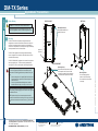
DM-TX Series
quickstart guide
DigitalMedia™ Transmitters
1
Before Starting
!
DM-TX-100/100-F
CAUTION: Do not connect power cords until instructed to do so.
HDMI
IN
USB HID
LAN
DM-TX-200
S G
IR
PWR
NOTE: Before beginning any of these QuickStart procedures, make
certain that all DigitalMedia™ cables are installed throughout the home.
Mounting Brackets (2)
DM LINK
Use appropriate hardware (not
supplied) to mount unit.
HDMI IN
SETUP
RESET
2
Mounting
The DM-TX-100/100-F has attached mounting brackets and is
designed to be mounted on a flat surface or attached to a rack rail in
the back of an equipment cabinet. It may also be used portably for
connection to a wall plate input, and is compact enough to fit discreetly
inside a presentation lectern or beneath a table.
The DM-TX-200, supplied with a mounting bracket and attaching
screws, is designed to be mounted on a flat surface and can even be
concealed inside a raceway.
DM-TX-100
Optional rack
rail mounting.
DM OUT
D
The DM-TX-300N/300N-F is designed to be mounted in an equipment
rack using supplied “ears.” These ears must be installed prior to
mounting the unit. The only tool required is a #2 Phillips screwdriver.
!
M
G
G B A 24
DM-TX-300N/300N-F
Mounting Ears (2)
Remove and use the three screws on each
side to attach the “ears” to the unit for rack
mounting. Do not attach if unit is to be placed
on a shelf or stacked. (Refer to NOTE at left.)
NOTE: If rack mounting is not required, rubber feet are provided for
tabletop mounting or stacking. Apply the feet near the corner edges on
the underside of the unit.
NOTE: Reliable earthing of rack-mounted equipment should be
maintained. Particular attention should be given to supply connections
other than direct connections to the branch circuit (e.g., use of power
strips).
1
For details, refer to the latest revision of the DM-TX-100, DM-TX-200,
and/or DM-TX-300N series DigitalMedia™ Transmitter Guides, Doc. 6810,
6741, or 6907, respectively.
QUICKSTART DOC. 6804C (2024043)
01.10
www.crestron.com
©2010 Specifications subject to
change without notice.
888.273.7876
201.767.3400
All brand names, product names, and trademarks
are the property of their respective owners.
Mounting Bracket
Use two screws (supplied) to
attach to unit for flush mounting.
Do not attach if unit is to be placed
in a raceway.
DM-TX Series
WARNING: To prevent bodily injury when mounting or servicing this
unit in a rack, take special precautions to ensure that the system
remains stable. The following guidelines are provided to ensure your
safety:
• When mounting this unit in a partially filled rack, load the rack
from the bottom to the top with the heaviest component at the
bottom of the rack.
• If the rack is provided with stabilizing devices, install the
stabilizers before mounting or servicing the unit in the rack.
DM-TX-Series
Connection to Room Controller (DM CAT)
Connecting to DigitalMedia Room Controller or DigitalMedia Switcher
Using a DigitalMedia™ cable (DM-CBL-P or DM-CBL-NP), connect the
transmitter(s) directly to a DigitalMedia Room Controller (if required, first connect
to a DigitalMedia Repeater and then connect the output of the repeater to a room
controller), or connect the transmitter(s) to a DigitalMedia Switcher (via a
DMC-CAT/DMC-F interface card).
Power Supply
PW-2407RU
(Not Supplied)
LA
N
IR
2
1 GSG
S
M
Y
LA
1
H
U
B
S
D
N
G X
T X
R TS
R TS
C
D
M
ID
T
SE
RE
CO
H
D
M
I
P
TU
SE
C
D
R
M K
D IN I
L DM
H
IN
IN B
G
R
P
U
T
E
S
R
W
P
IO
D
U
A
B
G
DM INK
L
EO
L
VID
TR
CN
R
D
E
M
R
S
-R
O
T
O
M
R
M
O
C
-1
N
C
O
0
0
N
T
R
O
L
L
E
R
4
2
A
B
G
T
U
O
M M
D
T
E
S
E
D
T igi
ra ta
n lM
sm e
it di
te a
r
IN
R
M
24 A B G
IN
2
B
MI
HD
NS
SE
Red
Orange
C
-RM
Black
Gnd
Gray
Connect the cable from the
PW-2407 power supply to
either end of the DigitalMedia
From
“DMNet” Cable, as shown in
PW-2407RU
the diagram to the right.
0
-10
SG
Dig
i
SwtalM
itc edi
he a
r
DM
“DMNet”
Control & Power
For details, refer to the latest revision of the DM-TX-100, DM-TX-200,
and/or DM-TX-300N series DigitalMedia™ Transmitter Guides, Doc. 6810,
6741, or 6907, respectively.
QUICKSTART DOC. 6804C (2024043)
01.10
UE
OT
S (SL
UT
TP
DM
7
ICS
, NJ
0764
CHO
C ELE
CTR
Fiber OR DigitalMedia
Cable
IGH
LE
CK
, RO
EL
2)
DE
: RISQ
INC
ON
TR
EC
ON
TR
OU
AVIS
A
US
ES
CR
P
TU
SE
IR
M
D
N
G X
T X
R TS
R TS
C
CO
D
M
4
G2 R
PW
DM INK
L
EO
L
VID
TR
CN
Y
LA
RE
1
5
IR
G
B HID
US
S
T
24
A
B
G
I-I
DV
MI
HD
Power supply
(supplied) required
for fiber configurations.
P
OM
IN
C/C
EO
Pr/
VID
/Y
Pb
0-F
I-I
DV
0
C-1
MI
HD
R
A
IN
47
T
OU
INC
, NJ
IGH
LE
CK
., RO
EC
EL
ICS
ON
TR
TRON
CRES
076
US
Fiber configurations
require local power
supplies (supplied).
Setting Up Ethernet
Setup of the IP address for the DigitalMedia transmitters depends on
the way the transmitters are configured within the DigitalMedia system.
1. Transmitters connected to a room controller use their own configuration settings. The units ship in DHCP mode, but the following
static addresses can be set on the units by holding the SETUP
button depressed while the unit boots up:
• The DM-TX-100, 200, and 300 series units default to
192.168.1.231/232/233.
• The DM-RMC-100/100-F defaults to 192.168.1.241/242.
NOTE: This process overwrites any current settings. Also, for the
DM-TX-100/100-F, the USB console is enabled and HID functionality
is blocked until reboot.
www.crestron.com
©2010 Specifications subject to
change without notice.
888.273.7876
201.767.3400
All brand names, product names, and trademarks
are the property of their respective owners.
IN
GND
TX
RX
RTS
CTS
R
A
IN
47
T
OU
TRON
CRES
LE
CK
., RO
EC
EL
ICS
, NJ
US
076
IGH
INC
ON
TR
IN
IN
DIO R
AU
L G +
+ -
-RM
DM
DIO
L
AU
DIF
SP
Y
MI
US
G
IN
DIO R
AU
L G +
+ -
DIF
SG
B
Y
P
TU
SE
SP
HD
NS
A
P
OU
DM
M
IN
24
IN
OM
IN
C/C
EO
Pr/
VID
/Y
Pb
G
N
LA
M
D
DIO
L
IR
G
S
T
OU
DM
M
CO
MI
AU
P
TU
SE
B HID
D
MI
HD
2
B
US
SE
2
1 GSG
S
G
N
LA
M
CO
HD
GND
TX
RX
RTS
CTS
R
PW
UT
INP
C
DM
DD
TT iiggii
rraa ttaa
nn llMM
ssm e
m ed
iitt dii
ttee aa
rr
M
D
R DM R
E
O
O -R S
M M T
R
C CO 1 ON
N 00
T
R -F
O
L
L
E
R
Power
Supply
(Supplied)
Power
Supply
(Supplied)
Fiber Cable
N
LA
D
T igi
ra ta
n lM
sm e
it di
te a
r
Connection to Room Controller (Fiber)
2. Transmitters connected to a DigitalMedia Switcher are
configured automatically by the switcher.
3. With a PC connected as shown in the diagram below,
use Crestron Toolbox™ to set the IP addresses of the
transmitter and room controller or DigitalMedia Switcher.
PC/Laptop
DigitalMedia
Transmitter
USB
Cable
OR
USB
Cable
Room Controller or
DigitalMedia Switcher
2
K
RIR
SHOC
OUV
TRIC
PAS
ELEC OPEN
OF
NE
RISK DO NOT
IQUE
G
A
7.0
0V~
-25 Hz
10050/60
Digita
lMedia
FiberOR
Cable
DM-TX-Series
The 300N/300N-F have front panel controls for making selections.
dia
M
The DM-TX-200 has auto routing functionality by default:
• If no signal is present on HDMI IN, RGB IN and AUDIO IN will be
routed.
• If a signal is present on HDMI IN and no audio is embedded in the
video, (i.e., a DVI signal) HDMI IN video and AUDIO IN audio will be
routed.
• If a signal is present on HDMI IN with audio embedded in the signal,
HDMI IN audio and video will be routed.
D
The DM-TX-100/100-F does not have video switching because there is only one
AV input.
Me
RE
Check that the DM input of the room controller or DigitalMedia Switcher are
connected to the transmitters, and connect/turn on power. Check the transmitter
LEDs, the output display, and verify the signal settings.
Check the room controller PWR LED ( on/green).
Check the DM LINK LED ( on/green).
Check that the VIDEO LED is on/green when a video signal is detected.
PW
US
Connecting AV Sources, Outputs, and Verifying Signals
•
•
•
ital
G
4
Dig
B
1. Configurations with a transmitter connected to a room controller require a
power supply, PW-2407RU, connected either to the transmitter or to the room
controller. For configurations using DM CAT cables, the power supply must be
purchased; for configurations using fiber cable, the power supply is provided.
3. For detailed instructions on the DigitalMedia Room Controller (DM-RMC-100
and DM-RMC-100-F) or the DigitalMedia Switcher, refer to the latest version
of their respective guides (Doc. 6743, 6744, and 6755) which can be obtained
from the Crestron website (www.crestron.com/manuals).
R
A
NOTE: DigitalMedia cable should have a minimum length of 15 feet (4.6 meters).
2. Configurations with a DigitalMedia Switcher may not require an additional
power supply; the switcher typically supplies power for the transmitter. Use the
Crestron Power Calculator to verify that there is enough DMNet power on the
switcher.
Connection to DigitalMedia Switcher
OR
D
3
24
quickstart guide
DigitalMedia™ Transmitters