1
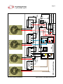
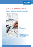
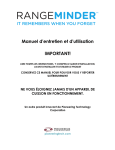
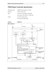
Installation Instructions
For PTI STEZA C (2x2 Burner Configuration) &
PTI STEZB C (3x1 Burner Configuration)
Revision E
Document Number PTI STE50 E
Safe-T-Element™ Installation Instructions
Table of Contents
1. PREPARATION……………………………………………………………………………..3
1.1 General Safety Instructions……………………………………………………...….3
1.2 Before You Start……………………………………………………………………...3
1.3 Tools & Equipment Needed………………………………………………………...4
1.4 Safe-T-Element™ Components…………………………………………………....4
1.5 Optional Components…………………………………………………………...…..5
1.6 Wiring Diagram……………………………………………………………………....7
2. INSTALLATION…………………………………………………………………………….8
2.1
Preparing For Installation………………………………………………………….8
2.2
Installing Safe-T-Element™ Plates……………………………………………….9
2.3 Mounting the Safe-T-Element™ Controller………………..……………………11
2.4 Connecting Power to the Safe-T-Element™ Controller…………………….....12
2.5 Connecting the Elements to the Safe-T-Element™ Controller.………..……..13
2.6 Connecting the Temperature Sensors to the Safe-T-Element™ Controller…14
2.7 Reassembly………………………………………………………………………...16
2.8 Testing………………………………………………………………………………17
3. FRONT-MOUNTED CONTROL SWITCH STOVES…………………………………..18
3.1 Preparation for Installation………………………………………………………….18
3.2 Mounting the Safe-T-Element™ Controller…………………...……………...…..18
3.3 Connecting Power to the Safe-T-Element™ Controller……………..……….….19
3.4 Connecting the Elements to the Safe-T-Element™ Controller……………...….19
4. INSTALLATION INSTRUCTIONS FOR PTI STEYA-WHIRPOOL ADAPTER…...22
4.1 Tools & Equipment Needed………………………………………………………..22
4.2 PTI STEYA Components…………………………………………………………..22
4.3 Installation…………………………………………………………………………...22
4.3a Preparing for Installation…………………………………………………...22
4.3b Installing the Adapter……………………………………………...………..23
5. INSTALLATION INSTRUCTIONS FOR PTI STEYC-GE JBP35 SERIES STOVE
ADAPTER…………………………………………………………………………...….….25
6. TROUBLESHOOTING…………………………………………………………………….26
6.1 Common Questions…………………………………………………………….…..26
6.2 Getting Help………………………………………………………………………….26
7. Safe-T-Element Controller Wiring Diagram…………………..………………..…….27
Page 3
PREPARATION
1.1 General Safety Instructions
Safety First!
Have your Safe-T-element™ installed by a qualified service technician.
Follow the installation and servicing instructions provided with this product.
Read this manual carefully before installing the Safe-T-element™ to reduce the
risk of electric shock, fire, burn hazard or other injury.
Extreme care should be used because of the high voltages used by the range
and this product. Disconnect the power to the range before removing the rear
cover.
Do not repair or replace any part of this product unless it is specifically
recommended in this manual.
A qualified service technician should conduct all other service.
Save these instructions for future reference. If you are installing this unit for someone
else, give this manual to him/her for future reference.
1.2 Before You Start
WARNING: Shock hazard present due to high voltages.
Disconnect power to range before installing this product.
Ensure that the power to the range remains OFF during the
entire duration of the Safe-T-element™ installation.
Ensure that the burners are cool before attempting to install this product.
Document Number PTI STE50 E
Safe-T-element ™ Installation Instructions
Page 4
1.3 Tools and Equipment Needed
Power Drill
3/16” Drill bit
#1 Phillips screwdriver
#2 Phillips screwdriver
Needle nose pliers
1.4 Safe-T-element™ Components
In addition to this manual, your Safe-T-element™ kit includes the following:
Quantity
2+2
Configuration
PTI STEZA C
Quantity
3+1
Configuration
PTI STEZB C
2
1
PTI STE28 D
Large plate
2
3
PTI STE29 D
Small plate
1
1
PTI STE18 -
Safe-T-Element™ Controller
4
4
PTI STEAY -
Controller mounting supports
4
2
PTI STE06 D
Large plate bracket
4
6
PTI STE07 D
Small plate bracket
24
24
PTI STEBA -
M3 x 4mm Screw
4
4
PTI STEBB -
M3 x 12mm Screw
2
2
PTI STEAX -
Nylon cable clip
4
4
PTI STEAW -
Nylon cable tie
2
1
PTI STE14 E
Thermocouple assembly for large plate
2
3
PTI STE15 E
Thermocouple assembly for small plate
4
4
PTI STE09 D
Thermocouple bracket
4
4
PTI STE10 C
Thermocouple wire support (M-Bracket)
4
4
PTI STE11 B
Thermocouple wire clip (S-Bracket)
Document Number PTI STE50 E
Part Number
Description
Safe-T-element ™ Installation Instructions
Page 5
Quantity
2+2
Configuration
PTI STEZA C
1
Quantity
3+1
Configuration
PTI STEZB C
1
Part Number
Description
PTI STE12 D
Wire set includes:
A. Power wire set
Includes:1 Black
1 White
B. Relay wire set
Includes:1 Blue
1 Red
1 Yellow
1 Brown
C. Extension wire set
Includes:1 Blue
1 Red
1 Yellow
1 Brown
1
1
PTI STE49 -
Care and Use Guide
1
1
PTI STE21 A
Warning Sheet
1
1
PTI STE27 A
Drill Template
2
2
PTI STE17 A
0.250” Tab, #10 Ring Terminal Adapter
1.5 Optional Components:
Some stove may require an adapter kit for the installation of the Safe-T-Element™ Controller. The
following is a partial list of adapter kits available. Please contact Pioneering Technology if unsure
whether an adapter kit is required for your stove.
Adapter Model No.
Description
Parts Included in Kit
PTI STEYA
Adapter for Whirlpool WERE3000
series stoves
•
•
External mounting bracket
3 Screws
PTI STEYC
Adapter for GE JBP35 series
stoves
•
•
Mounting bracket
Screw
Document Number PTI STE50 E
Safe-T-element ™ Installation Instructions
Page 6
Ensure that the Safe-T-Element™ is compatible with the stove. Some stove models may require
the replacement of the burners or the use of an adapter kit.
Check the construction of the burners.
The Safe-T-Element™ plates cannot be mounted
to burners with a ‘delta’ or triangular spider. The
burners will need to be replaced with compatible
burners with the 3 legged spider.
The Safe-T-Element™ plates are not compatible
with some GE and Hotpoint small 6” burners with
5 turns of the element coil. They must be
replaced with compatible 4-turn elements.
Certain models like the Whirlpool WERE3000
series of stoves do not have enough space in the
rear compartment for the installation of the Safe-T-Element™ controller. In this case an adapter kit
available from Pioneering Technology must be used for mounting of the controller.
IMPORTANT
This document describes a typical installation.
There are slight variations from model to model which must be
accommodated. Please contact Pioneering Technology for
assistance
Document Number PTI STE50 E
Safe-T-element ™ Installation Instructions
Page 7
1.6 Wiring Diagram
15A
White
P1
Black
P2
POWER
SUPPLY
REGULAR OUTLET
NEUTRAL
L1
H1
H2 L2
R.F. UNIT ELEMENT
L1
Blue
R. F. SW.
Blue
P
TEMPERATURE
CONTROL
Neon Lamp
P.L.
OPTIONAL
P
L1
Neon Lamp
Red
H2 L2
L1
Red
H1
R.R. UNIT ELEMENT
TEMPERATURE
CONTROL
R. R. SW.
CONTROL BOARD
L1
H2 L2
H1
Yellow
L. F. SW.
L.F. UNIT ELEMENT
Yellow
P
L1
Neon Lamp
P.L.
OPTIONAL
L1
TEMPERATURE
CONTROL
P
Neon Lamp
Brown
H2 L2
L1
Brown
H1
L1
L.R. UNIT ELEMENT
L. R. SW.
Original wiring
STE wires provided with Kit
Document Number PTI STE50 E
TEMPERATURE
CONTROL
L2
Safe-T-element ™ Installation Instructions
Page 8
2. INSTALLATION
2.1 Preparing For Installation
1. Before disconnecting anything test surface elements and oven to ensure they are functional. To
prevent injury do not allow elements to get hot.
Turn elements off when slightly warm.
2. Disconnect power to stove.
WARNING: Failure to disconnect power
will result in a hazardous situation.
3. Remove screws securing the rear cover of the
stove.
For Front-mounted Control Switch Stoves,
please refer to Section: 3.1 on Page: 18
4. Inspect all existing wiring for damage or excessive
grease buildup.
WARNING: Do not proceed with the installation if there is any damage to wiring
or excessive grease buildup.
To avoid risk of personal injury or property damage,
have the stove serviced before proceeding with the
installation if either of these conditions is found.
Document Number PTI STE50 E
Safe-T-element ™ Installation Instructions
Page 9
2.2 Installing Safe-T-element™ Plates
1. IMPORTANT!
Verify that the power supply to the stove is disconnected and the burner elements
are cool.
2. Remove burner element from its socket.
3. Remove its center cover piece.
4. Put the thermocouple wire through the gap in the
element as shown, carefully, holding it by the wire
only.
CAUTION!
HOLD & BEND THE THERMOCOUPLE WIRE
ONLY. DO NOT HOLD OR BEND THE WIRE WITH
THE THERMOCOUPLE BRACKET AS IT MAY
BREAK THE THERMOCOUPLE JUNCTION ON
THE BRACKET.
5. Put the other end through the next gap as shown
carefully, holding it by the wire only.
Document Number PTI STE50 E
Safe-T-element ™ Installation Instructions
Page 10
6. Hold the thermocouple wire bracket in place.
Where possible, the bracket should be mounted
behind the existing element grounding bracket.
Where this is not possible, the temperature sensor
bracket may be mounted in front of the element
grounding bracket provided the following
requirements are met:
• The temperature sensor bracket can be
mounted in a position where it can hook onto
the element grounding ground bracket to prevent movement; and,
• A minimum spacing of ½ inch is left between
the temperature sensor bracket and the
exposed terminals of the element.
NOTE:
The kit includes 2 different size sensors.
Ensure you mount the correct one for the element.
7. Secure the temperature sensor bracket to the
element.
8. Place the Safe-T-element™ plate top-side down.
Place cook element top-side down on the Safe-Telement™ plate.
The electrical connections for the element should be
placed opposite the notch in the plate.
9. Loosely secure the Safe-T-element™ plate to the
burner element using thermocouple assembly
bracket and 2 screws (PTI STEBA) using the #1
Phillips screw driver
10. Use 2 additional brackets to secure the plate to the
element.
Tighten the 6 screws until the bracket is snug
against the plate. Be careful not to over tighten the
screws.
11. Repeat the above steps for the other 3 burner
elements.
Document Number PTI STE50 E
Safe-T-element ™ Installation Instructions
Page 11
2.3 Mounting the Controller :
1. Place the adhesive back drill template for the
Controller in the lowest possible location INSIDE the
stove rear compartment. The photo shows a typical
mounting location
For Front-mounted Control Switch Stoves,
please refer to Section: 3.2 on Page: 18
WARNING
•
•
•
•
•
The Controller location must meet the following
requirements:
It must be placed as low as possible in the rear
compartment of the range in order to minimize exposure to heat.
In no case should the template be placed directly
above the terminals for the oven element as heat
escaping from the opening may cause the Controller to overheat.
A minimum 1 inch gap is maintained between the
Controller and any other range component such
as terminal blocks, oven components, etc.
The controller and all wires are completely enclosed in the rear compartment.
For Stoves such as the Whirlpool Model #
WERE3000 which have a shallow rear compartment will require an adaptor kit to accommodate the Controller . This adaptor kit will allow
the mounting of the Controller outside the rear
panel. Please contact Pioneering Technology if
one is required for your stove). Please refer to
Section: 4 on page:23 for more details on in
stallion of this kit.
A minimum of ¼ inch is maintained between the tallest component on the Controller and the rear cover.
2. Drill 4 holes using a 3/16” drill bit.
WARNING
Be careful to drill through the rear panel only.
Drilling deeper than ½ inch will cause damage to
the oven wall.
3. Remove the template. Insert the Controller mounting
supports as shown. (Insert wide end of support into
hole)
Document Number PTI STE50 E
Safe-T-element ™ Installation Instructions
Page 12
4. Secure the Controller to the supports as shown.
Ensure each support is fully inserted.
WARNING
Apply pressure only from the left and right edges.
Pressure to the middle of the board will cause it to
flex and may damage the circuit.
2.4 Connecting Power to the Controller
WARNING
The controller is designed to operate on
120VAC only, DO NOT apply or connect it to
220VAC!
For Front-mounted Control Switch Stoves,
please refer to Section: 3.3 on Page: 19
1. Connect the BLACK wire to terminal P1 on the STE
Controller.
2. Locate the fuse for the 120VAC outlet on the range.
Disconnect the wire which goes to the 120VAC outlet.
NOTE: For stoves without a fuse or where the fuse is not
accessible, the Black wire from the STE controller
may be connected directly to the black wire from
the power cord.
If necessary use ring terminal adapter provided.
3. Connect the BLACK wire from the STE Controller to
the fuse holder.
Document Number PTI STE50 E
Safe-T-element ™ Installation Instructions
Page 13
4. Re-connect the wire from the 120V outlet to the piggyback connection on the STE wire.
5. Connect the WHITE wire to the P2 terminal on the
Controller.
NOTE: For stoves without an oven light or where the
oven light is not accessible, the White wire from
the STE controller may be connected directly to
the white wire from the power cord.
If necessary use ring terminal adapter provided.
6. Remove the white wire to the oven light. Connect the
Safe-T-Element wire to the oven light.
7. Re-connect the wire to the light.
2.5 Connecting the Elements to the Controller
For Front-mounted Control Switch Stoves,
please refer to Section: 3.4 on Page: 19
1. Connect the 90º connector on the BLUE relay wire to
the NO terminal on the upper-right relay of the STE
Controller (when looking at the STE Controller from
the back)
2. Locate the temperature control dial for the front-left
element. (when looking at the electric range from the
front). Disconnect the wire going from the dial to the
cook element.
.
Document Number PTI STE50 E
Safe-T-element ™ Installation Instructions
Page 14
3. Connect the other end of the BLUE relay wire to the
temperature control dial.
4. Connect the BLUE relay extension wire provided to the
wire coming from the front-left element
To prevent possible fire or electric shock ensure that the blue insulator completely covers
the connection.
5. Connect the BLUE relay extension wire to the COM
terminal of the upper right relay of the STE Controller.
6. Using the RED wire repeat steps 1 through 5 to
connect the rear-left element (looking at the range
from the front) to the lower-right relay of the STE Controller.
7. Using the BROWN wire repeat steps 1 through 5 to
connect the rear-right element (looking at the range
from the front) to the lower-left relay of the STE Controller.
8. Using the YELLOW wire repeat steps 1 through 5 to
connect the front-right element (looking at the range
from the front) to the upper-left relay of the STE Controller.
9. Secure all the wires using cable ties.
2.6 Connecting the Temperature Sensors to the
Controller
1. Hold the M-Bracket firmly with both hands and pull
outward slightly. This will make installation of the
wire easier.
This bracket is used to help support the thermocouple bracket. It may not be necessary on the rear elements or where existing supports in the stove may
be used.
Document Number PTI STE50 E
Safe-T-element ™ Installation Instructions
Page 15
2. Place the M-Bracket approximately 4 inches from
the end of the thermocouple extension wire. Press
one end of the bracket onto the thermocouple wire.
3. While holding that end press the other side of the
bracket onto the wire.
4. Press the center portion of the wire in until it is
completely in the slot on the M-bracket.
5. Place the thermocouple wire under the range top
leaving approximately 6 inches protruding from the
front-left opening.
6. Secure the thermocouple wires under the cook top in
the same manner as the existing wires to the
elements.
If stove does not have channels as shown or similar
supports then hang the thermocouple wires of the
front elements from the stove element wires using the
S-clips provided.
Document Number PTI STE50 E
Safe-T-element ™ Installation Instructions
Page 16
7. Re-install the drip pan as shown.
8.Connect the thermocouple wire to the thermocouple on
the plate.
9. Re-install the element.
10. Connect the thermocouple to the upper-right terminal
of the STE Controller (i.e. same channel as the relay
wires for that element)
11. Repeat for the 3 other elements.
2.7 Reassembly
1. Tie the 4 thermocouple wires together near the
STE Controller using one of the cable ties provided.
Document Number PTI STE50 E
Safe-T-element ™ Installation Instructions
Page 17
2. Remove a screw on the rear-right side (or left side –
depending on which side the controller was
mounted) on the range.
3. Secure the thermocouple wires using a cable clamp
and the screw.
WARNING Be careful not to damage any of the
wires during reassembly. Any wire damaged
during the installation must be replaced prior to
applying power to the range.
5. Re-connect the power cord.
2.8 Testing
1. Place your hand on the front-right plate and turn on
the element. Ensure that the light for that element
lights up.
2. Feel for heat from the plate. Be extremely careful
during this test as the element may heat up very
quickly. Move your hand away at the first sign of
heat.
3. Turn off the element. Repeat for other elements.
4. Installation is complete.
Document Number PTI STE50 E
Safe-T-element ™ Installation Instructions
Page 18
3. Front-Mounted Control Switch Stoves
3.1 Preparation for Installation
Remove screws securing the rear cover of the stove.
3.2 Mounting the Controller
Document Number PTI STE50 E
Safe-T-element ™ Installation Instructions
Page 19
3.3 Connecting Power to the Controller
3.4 Connecting the elements to the Controller
1. Connect the 90º connector on the RED relay wire to
the NO terminal on the lower-right relay of the STE
Controller (when looking at the STE controller from
the back)
2. Route the wire through the space above the oven and
over to the front mounted temperature control dials.
Document Number PTI STE50 E
Safe-T-element ™ Installation Instructions
Page 20
3. Remove the top panel to access the front mounted temperature control dials.
4. . Locate the temperature control dial for the rear-left
element (when looking at the range from the front)
5. Disconnect the wire going from the dial to the cook
Element.
6.. Connect the other end of the RED relay wire to the
temperature control dial.
7. . Connect the RED relay extension wire provided to the
wire coming from the rear-left element.
Document Number PTI STE50 E
Safe-T-element ™ Installation Instructions
Page 21
WARNING
To prevent possible fire or electric shock ensure that the blue insulator completely covers
the connection.
8. Connect the RED relay extension wire to the COM
terminal of the lower-right relay of the STE Controller.
9. Using the BLUE wire repeat steps 1 through 5 to
connect the front-left element (when looking at the
range from the front) to the upper-right relay of the
STE Controller.
10. Using the BROWN wire repeat steps 1 through 5 to
connect the rear-right element (when looking at the
range from the front) to the lower-left relay of the STE
Controller.
11. Using the YELLOW wire repeat steps 1 through 5 to
connect the front-right element (when looking at the
range from the front) to the upper-left relay of the STE
Controller.
12. Secure all the wires using cable ties.
Document Number PTI STE50 E
Safe-T-element ™ Installation Instructions
Page 22
4. Installation Instructions for PTI STEYA Control Board Adapter
Stoves such as the Whirlpool Model # WERE3000 which have a shallow rear
compartment will require an adapter kit to accommodate the Controller . This
adapter kit will allow the mounting of the Controller outside the rear panel.
Please contact Pioneering Technology if one is required for your stove).
4. 1 Tools and Equipment Needed
Aviation snips
Needle nose pliers
Power drill
1/8” drill bit
Metal punch
4.2 PTI STEYA Components
Your PTI STEYA Whirlpool Adapter kit includes the following:
Quantity
Part Number
Description
1
PTI STEYA -
Controller mounting bracket + Cover
4
PTI STEAX -
# 8 x 1/2" metal self-tapping screw
1
PTI STEBC -
Nylon cable clip
2
PTI STEAW -
Nylon cable tie
4.3 Installation
4.3a Preparing for Installation
Description
1. Disconnect power to stove.
WARNING: Failure to disconnect power
will result in a hazardous situation.
2. After removing lower cover cut a notch out of
the lower-right corner of the cover
approximately 1¼” wide by 1¼” high.
Document Number PTI STE50 E
Safe-T-element ™ Installation Instructions
Page 23
3. Bend approximately ¼” of the cover inward at
the top of the cut to prevent the sharp edge of the
cover from coming in contact with the wires.
4.3b Installing the Adapter
1. Hold the bracket in place as shown in the picture and mark the three holes using a pencil or
marker.
2. Use a metal punch to mark the center of the
holes and drill three 1/8” holes.
3. Mount the Controller on the bracket bringing all
the wires out the opening. Use a cable tie to
secure the wires.
Document Number PTI STE50 E
Safe-T-element ™ Installation Instructions
Page 24
4. Place cover on the back of the bracket.
5. Mount the Adapter using 3 screws provided.
6. Use the cable clamp and screw provided to
secure the thermocouple wires away from the
power terminals. Use an existing hole in the
stove if possible.
6. After completing the rest of the Safe-Telement™ installation reinstall the lower rear
cover.
Document Number PTI STE50 E
Safe-T-element ™ Installation Instructions
Page 25
5. Installation Instructions for PTI STEYC-GE Model JBP35 series
Safe-T-Element™ Controller Adapter
Some GE stoves like the JPB35 series have a very
shallow rear compartment will require an adapter
kit to accommodate the STE Controller . This
adapter kit will allow the mounting of the Controller behind the rear panel. Please contact Pioneering Technology if one is required for your stove.
Installation
Description
1. Disconnect power to stove.
WARNING: Failure to disconnect power will
result in a hazardous situation.
2. Remove stove rear panel.
3. Mount the Controller on the adapter plate, using the
PCB supports.
4. Secure the bottom edge of the adapter plate and
use the screw provided to hold the top.
5.. Refer to section 2.4 to 2.6 for wiring of the power
wires, relay wires and the thermocouple wires to the
STE Controller.
Document Number PTI STE50 E
Safe-T-element ™ Installation Instructions
Page 26
6. TROUBLESHOOTING
6.1 Common Questions
PROBLEM
POSSIBLE CAUSE/SOLUTION
Stove does not operate
Cord not plugged into wall. Ensure power cord is
plugged into outlet.
Fuse has blown or circuit breaker has tripped.
Check range fuses and breaker at panel.
One element does not operate
One or more of the elements
get too hot (up to 450°C)
One or more of the elements
get too hot (greater than
450°C)
WARNING: Do not reset breaker/replace fuse
until cause is identified and corrected. Failure to
do so may result in injury or damage.
Thermocouple wire connection broken.
Ensure thermocouple wire connected.
Check thermocouple wire for damage.
It is normal to have hot spots on the plate if the
Safe-T-Element™ is operated without a pot or
pan. The Safe-T-Element™ is designed to keep
the average temperature of the plate at
approximately 350°C. If the element is
operated without a pot or pan then there may be
some hot spots due to irregular heating by the
element below. This is normal provided that the
highest temperature does not exceed 450°C.
Thermocouple wire has a short circuit. Check
wire for damage. Replace if necessary.
Safe-T-element™ is not connected properly.
Check wiring and ensure thermocouple and relay
wires are connected correctly.
Controller defective. Replace controller and test
again.
6.2 Getting Help
If you require assistance with the installation of Safe-T-Element™ please call
Pioneering Technology Inc. at toll free: 1-800-433-6026 or 905-712-2061 between
the hours of 9:00am and 5:00pm EST or email: [email protected].
Document Number PTI STE50 E
Safe-T-element ™ Installation Instructions
Document Number PTI STE50 E
Yellow Wire
(REW)
Brown
Relay
Blue Wire (REW)
STE
Control Board
P1
COM
Red
Relay
NO
Blue
Relay
H2 H1
Blue Wire
(RW)
Yellow
C
Yellow Wire
(RW)
NO
Neo
n
H2 H1 P L1
N
Oven
Light
Brown Wire (RW)
Brown Wire (REW)
light is not accessible
Relay
Wire
P L1
v
15A
Neon
Light 4
Alternate Wiring: for
stoves without fuse
L2
Black Wire
240 VAC Power
In Wiring: if Oven
Alternate
L1
Red Wire
White Wire
Relay
Extension
Wire(REW)
H2 H1
Rear-Left
Control Switch
L2
Rear-Left Element
Neon
Light 3
P L1
Front-Left
Control Switch
L2
Front-Left Element
Red Wire
STE Controller Wiring
Neon
Light 1
H2 H1 P L1
Front-Right
Control Switch
L2
Front-Right Element
Rear-Right
Control Switch
L2
Rear-Right Element
Page 27
Safe-T-element ™ Installation Instructions