1
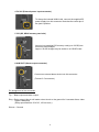
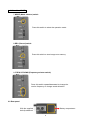
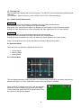
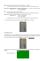
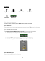
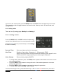
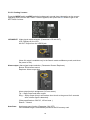
®
AR-STV
WIRELESS CAMERA DETECTOR
Operating manual
AOR, LTD.
TABLE OF CONTENTS
1 Introduction -------------------------------------------------------------------------------------1-1 Maintaining the unit --------------------------------------------------------------------------1-2 Power requirements -------------------------------------------------------------------------1-3 Supplied accessories -----------------------------------------------------------------------1-4 Features -----------------------------------------------------------------------------------------
2
2
2
3
3
2 Control and functions------------------------------------------------------------------------- 3
2-1 Front panel controls--------------------------------------------------------------------------- 3
2-2 Rear Panel -------------------------------------------------------------------------------------- 6
3 Connections--------------------------------------------------------------------------------------- 7
4 Power Switch------------------------------------------------------------------------------------- 7
5 Operations of the AR-STV ------------------------------------------------------------------5-1 Display ------------------------------------------------------------------------------------------5-2 Operation mode ------------------------------------------------------------------------------5-2-1 Search mode -------------------------------------------------------------------------------5-2-2 Memory mode ------------------------------------------------------------------------------5-2-3 Setting mode -------------------------------------------------------------------------------5-3 PC interface ------------------------------------------------------------------------------------
7
7
8
8
11
13
15
6 Specifications------------------------------------------------------------------------------------ 16
7 Limited warranty (USA only)---------------------------------------------------------------- 17
FCC statement
This device complies with Part 15 of the FCC rules. Operation is subject to the following two
conditions:
(1) This device may not cause harmful interference, and (2) This device must accept any
interference received, including interference that may cause undesired operation.
1
1 Introduction
Thank you for purchasing the AR-STV Wireless Camera Detector.
The AR-STV is a wireless camera receiver with a 2.5 inch color LCD display, still picture recorder
and sensor that captures analog video signals in real-time. It is mainly designed for use in
surveillance applications.
Its built-in clock allows images to be time-stamped and a (non-supplied) SD memory card can be
used to store images.
© This manual is protected by copyright AOR, LTD. 2013. No information contained in this manual
may be copied or transferred by any means without the prior written consent of AOR, LTD.
AOR and the AOR logo are trademarks of AOR, LTD. All other trademarks and names are
acknowledged.
1-1 Maintaining the unit
There are no internal operator adjustments. In the unlikely event of service being required, please
contact your dealer for technical assistance.
Level of risk:
As the AR-STV operates with a 6 V DC power source, there is little chance of serious injury as long
as common sense is applied.
Observe the polarity of connections if using an external battery charger. DC input is a nominal 6V
DC, with the connector wired center conductor positive. Reverse polarity connection will damage the
AR-STV and could lead to the risk of fire or explosion under severe circumstances.
NEVER connect the AR-STV directly to the AC outlet.
Handling the AR-STV:
Use a soft, dry cloth to gently wipe the AR-STV clean. Never use abrasive cleaners or organic
solvents which may damage certain parts. Treat the unit with care, avoid spillage or leakage of
liquids into the cabinet and power supply. Special care should be taken to avoid liquid entering
around the keys, main dial or via the connectors.
[Note: Never push or knock the LCD screen – it is very fragile and sensitive to shock.]
Special remarks:
Do not use or leave the AR-STV in direct sunlight (especially the TFT display). It is best to avoid
locations where excessive heat, humidity, dust and vibration are expected. Always keep the AR-STV
free from dust and moisture.
1-2 Power requirements
The AR-STV is designed for operation from a nominal 6 V DC (4 AA size alkaline battery or Ni-MH
cells). The external 6V DC power supply may be used to charge the internal Ni-MH cells.
Do not use an external power supply when alkaline battery cells are in the unit.
[ Notice: Always disconnect the external power supply when in use.]
2
1-3 Supplied accessories
The following accessories are provided in the shipping box.
Instruction manual (this booklet)
Flexible rubber antenna
Belt clip
Soft case
Four AA size Ni-MH battery cells
DC power supply / battery charger
1-4 Features
Built-in 2.5 inch color LCD display
Built-in clock for time stamp
Store images on a (non-supplied) SD (or SDHC) memory card
Detect NTSC, PAL, CCIR, EIA or scrambled reverse polarity video signals
Receives and displays video signals on L-band (1.2 GHz) or S-band (2.4 GHz)
The USB connector makes it easy to download stored images into a computer
Easy to operate with four AA size batteries
Continuous search between 900 ~ 2800 MHz
10 search banks
Easy menu-driven operation
2 Controls and functions
2-1 Front panel
The front panel of the AR-STV is dominated by the large color LCD. On the top right corner of the
AR-STV, there is a red LED marked as “STA” (Status). The LED blinks while in the search mode.
Front View
3
Left View
Right View
Right Side of the AR-STV
1 Power ON/OFF switch
Slide the power switch upward to switch on the AR-STV.
To switch off the AR-STV, slide the switch downward.
2 CONT (USB connector)
Using a USB A ←→ USB Mini (B) cable (not supplied),
connect between the CONT (Control) connector and a
PC to download images which have been previously
3 VIDEO (Video Output connector)
This 3.5 mm mono connector provides the
composite video output.
An external video monitor may be connected.
4
4 DC 6V (External power input connector)
To charge the internal Ni-MH cells, connect the supplied DC
power supply into this connector. Note that the center pin of
the jack is positive.
5 SD (SD, SDHC memory card slot)
Insert a (non-supplied) SD memory card (up to 32 GB) into
this slot to save images.
Approx. 20,000 images may be saved on a 1GB SD card.
6 ALM OUT (Alarm output connector)
Connect an external alarm device into this connector.
(Format: 3.5 mm stereo)
Pin assignment of the connector:
Tip --- Beep output and alarm output
Ring --Relay output (this pin will make a short circuit to the ground for 2 seconds after a video
signal is detected)
(Relay specifications: 50 V DC, 150 mA max.)
Sleeve--- Ground
5
Left Side of the AR-STV
7 MODE (Mode selector) switch
Press this switch to select the operation mode.
8 REC (Record) switch
Press this switch to store image onto memory.
9 FREQ UP DOWN (Frequency selector switch)
Press this switch upward/downward to change the
receive frequency or change search direction.
2-2 Rear panel
Battery compartment
With the supplied
belt clip attached.
6
3 Connections
Connect the supplied flexible rubber antenna to the SMA antenna connector on the top of the ARSTV.
If required, an external antenna may be connected with a SMA connector for the coaxial cable.
Insert the supplied 4 AA size Ni-MH cells into the
battery compartment in the AR-STV.
If the batteries are not yet charged, connect the
DC power supply into the power input connector on
the right side.
4 Power switch
To switch on the AR-STV, slide the power switch on the right side of the AR-STV upward.
4-1 Start-up
After inserting the batteries, switch on the power switch. The LCD displays search screen
and a STA (Status) LED will blink indicating the AR-STV is in the search mode.
4-2 Powering down
To switch off the AR-STV, slide down the power switch.
4-3 Low Battery
When internal battery voltage becomes low, the Low Battery indicator will appear on the LCD
screen. In the meantime, a beep will sound.
When this message appears on the screen, all operations of the ARSTV will quit automatically. Immediately switch off the AR-STV, and
replace all internal battery cells with new ones or charge the supplied
batteries by connecting the DC powers supply. (Charging time approx.
10h)
5 Operations of the AR-STV
To set or remove the key lock, press the blue button and FREQ.DOWN switch simultaneously.
5-1 Display
This section explains what you can expect to see on the AR-STV
LCD monitor screen.
Once the AR-STV is properly powered up, this display will
appear on the screen:
7
(1) 1G 2G 3G (Hz)
The horizontal axis displays the receive frequency. The AR-STV can receive between 900 MHz and
2800 MHz.
(1G indicates 1 GHz in frequency, 2 G for 2 GHz, and 3 G for 3 GHz accordingly.)
(2) V (Video level) N (Noise level)
Video Level
The V (Video) line on the vertical axis displays the video quality threshold level.
Note that video level is NOT related to the signal strength.
Setting the video threshold level higher will display the video signal only with the better quality.
Setting the video threshold level lower will display the video signal even if it is of poor quality.
Noise Level
The N (Noise) line on the vertical axis displays the signal strength.
Setting the Noise threshold level higher can detect only strong signals.
Setting the Noise threshold level lower can detect any weak signals even of poor quality.
Video Level and Noise level can be adjusted on the Search Bank Setting Menu.
5-2 Operation Mode
There are three (3) operation modes with the AR-STV.
•
•
•
Search Mode
Memory Mode
Setting Mode
5-2-1 Search Mode
This is a default operation mode of the AR-STV. On this mode, the AR-STV will search frequencies
between 900 MHz ~ 2.8 GHz (2800 MHz) continuously until signal is detected.
Once the AR-STV detects the signal, it will automatically
switch the screen to display the received video signal.
To stop searching, press the FREQ switch inward. Then
the screen on the right will appear.
8
Icon legend:
Signal level
Battery level
Search bank
Receive freq.
SD card inside
Search mode
5-2-1-1 Frequency adjustment
To change the receive frequency, press the FREQ. switch upward or downward.
5-2-1-2 Recording image
To record the received image, press and hold the REC switch for 3 seconds.
(Note: To record an image, a non-supplied SD memory card must be installed in the AR-STV.
Otherwise, a beep will sound, and the SD Error message will appear on the LCD screen.)
5-2-1-3 Search Bank setting
To register a search bank, perform the following steps:
9
1. On the Search Mode screen, press and hold the MODE switch for 3 seconds
2. The following search bank setting screen will appear.
Search: Search bank number 0 ~ 9. To change the search bank, press the MODE key.
Start: Select the start frequency. (Frequency range: 900 ~ 2800MHz). On above example, 09 is
highlighted in reverse color and 900 MHz has been set as the start frequency.
To change the first 2 digits, press the FREQ. Switch inward. The highlighted area will change
into green, indicating it is ready to change the parameter.
Press the FREQ. switch upward or downward to select the desired frequency.
To confirm entry, press the FREQ. switch inward again. The highlighted area will change into
white.
To change the last 2 digits of frequency, press the FREQ. switch downward. Repeat above
steps to change the last 2 digits of frequency.
End:
Select the end frequency. (Frequency range: 900 ~ 2800MHz). On the above example,
2800 will be highlighted in reverse color as 2800 MHz has been set as the end frequency.
To change the end frequency, perform the same procedures as the start frequency entry.
10
Step: Select the search frequency step. (Entry range: 2 ~ 10 MHz)
To change the parameter, perform the same procedures as the start frequency entry.
Noise Level: Select the noise threshold level. (Entry range: -30 ~ -80 db min 5 dB increments)
Suggested level:
75 (for normal search)
0 (for weak signal)
Run: Select the search bank enable or disable.
To change the parameter, perform the same procedures as the start frequency entry
Video Level: Select the video threshold level. (Entry range: 0 ~ 95 %)
Suggested level:
60 (for normal search)
20 (for weak signal)
If the parameter is set to 0, then the AR-STV searches with the noise level setting.
3. To exit from this setting screen, press and hold the MODE key for 3 seconds.
5-2-2 Memory mode
In the Memory mode, you can change the memory channel setting, record images into memory.
To use this function, a formatted SD memory card (not included) must be inserted in the SD slot.
To go into the Memory mode, press the MODE key and REC key simultaneously.
(If no SD memory card is in the slot, a beep will sound and a “SD Card No File” error message
appears.)
Memory mode screen:
11
Icon legend:
Signal level
Battery level
Search bank
Receive freq.
SD card inside
Search mode
5-2-2-1 Scroll memory channel
To scroll the memory channel, press the FREQ. switch upward or downward.
5-2-2-2 Slide show
To start a slide show of the recorded frequencies, press and hold the FREQ. switch for 3 seconds.
5-2-2-3 Change memory contents
To change the recorded frequency of the memory channel, perform the following steps:
1. Press and hold the MODE switch for 3 seconds.
2. The frequency on the top right of the LCD will display in reverse color.
3. Press the FREQ. switch upward or downward to change the frequency.
4. To confirm entry, press and hold the FREQ. switch again for 3 seconds.
5-2-2-4 Recording image
Press and hold the REC switch for 3 seconds.
12
To return to the search mode, press the MODE switch and REC switch simultaneously three times.
(The operation mode will toggle between the Search mode, Memory mode, SD card mode, and
setting mode.)
5-2-3 Setting mode
There are two (2) setting pages: Setting 1 and Setting 2.
5-2-3-1 Setting 1 screen
Press the MODE switch and REC switch simultaneously
several times (depending on the current operation mode).
(Press the blue button to proceed directly to the settings
2 screen if needed.)
Date and Time:
Set current date and time for time stamp.
View Time:
Duration of pause time. (Parameter: 1 ~ 50 (seconds), STOP)
Set the view time before resuming search after detecting video signal. If set to
STOP, the AR-STV stops searching once video signal is detected.
Video Polarity:
Reverse video polarity (ON/OFF)
•
•
•
•
To change each parameter, press the FREQ. switch upward or downward to move the cursor
to the desired position.
Press the FREQ. switch inward to change the color of the selected parameter in reverse
polarity with green color.
Press the FREQ. switch upward or downward to change the parameter.
To confirm entry, press the FREQ. switch inward.
To leave the settings screen, press simultaneously on the blue and red buttons once, then wait 3
seconds.
13
5-2-3-2 Setting 2 screen
Press the MODE switch and REC switch simultaneously several times (depending on the current
operation mode) until the SETTINGS 1 screen appears, then press the blue button to get to the
SETTINGS 2 screen
LCD/AVOUT: Video signal output selection. (Parameter LCD/ AV OUT)
LCD: Displays on the LCD
AV OUT: Output from the VIDEO jack.
(Note: AV output is available only in the Search mode and Memory mode, and when
the power is ON.)
Alarm output: Alarm signal output selection. (Parameter: Buzzer/ Earphone)
Buzzer: Emits buzzer sound
Earphone: Alarm output jack
Alarm output jack pin assignment (3.5 mm stereo)
Tip --- Beep output and alarm output
Ring --- Relay output (this pin will make a short circuit to the ground for 2 seconds
after a video signal is detected).
(Relay specifications: 50V DC, 150 mA max. )
Sleeve--- Ground
Auto Save:
Auto image save function (Parameter: ON/ OFF)
ON: Detected image is automatically saved on the SD memory card.
14
OFF: Detected image will NOT be saved on the SD memory card automatically.
NTSC/PAL:
Video detector mode (Parameter: NTSC/ PAL)
Select the video receive mode.
Power Save: Battery power save function (Parameter: ON/ OFF)
ON: To save battery consumption during search, the power to the LCD will be turned
off.
If there is no activity for more than 30 seconds, the power to the LCD will also be
turned off.
OFF: This function will be disabled.
Relay:
Activate / deactivate an alarm relay. (Parameter: ON/ OFF)
The relay output is labeled “ALM out” and located on the right side of the device.
ON: When video signal is detected, then it will trigger the internal alarm relay.
OFF: The relay operation is disabled.
To leave the settings screen, press simultaneously on the blue and red buttons once, then wait 3
seconds.
5-3 PC interface
The AR-STV provides a USB interface for a PC. (USB cable not supplied)
The memory contents on the SD memory card can be transferred to a PC through the USB
interface.
The stored image has following data format:
Folder’s name: \DCIM\100ARSTV
File name: AORSxxxx.JPG (xxxx : 0001 ~ 9999)
Memory card: Memory size: Up to 32GB
File system: FAT32
(Caution: Do not eject the SD memory card while in the data writing mode or reading mode.)
15
6 Specifications
Frequency Coverage:
Receive Mode:
Receiving system:
IF (Intermediate frequency):
Memory channels:
Search banks:
Search speed:
Frequency step:
Sensitivity:
Antenna impedance:
Antenna connector:
Antenna:
Power requirements:
External input voltage:
Current drain:
Operating environment:
Relay output for alarm:
Relay specs:
Recording media:
Picture size:
Memory contents:
Video output:
Dimensions:
Weight:
900 ~ 2,800 MHz continuous
FM Video
Single conversion super heterodyne
479.5 MHz
10
10
Approx. 6 seconds for entire range (@10MHz steps)
2 MHz ~ 10 MHz (in 1MHz incremental)
-79 dBm (@1.2 GHz)
-83 dBm (@2.4 GHz)
50Ω
SMA
Dual band flexible rubber antenna (approx.3.5 inches in length)
4 – AA size alkaline battery cells (1.5 V x 4) or
4 - AA size Ni-MH cells (1.2 V x 4)
4.8 ~ 6.0 V DC 500 mA
Approx. 540 mA (in search mode with battery save function)
Approx. 600 mA (in display mode)
0 ~ 50 degrees (C), 32 ~ 144 degrees (F)
-20 ~ +70 degrees(C) , -4~ + 158 degrees (F) for storage
3.5 mm stereo type jack
Activates for 2 seconds after detecting a video signal.
50 V DC max./ 150 mA max. / 100 mW max.
SD/SDHC (32 GB max.*), FAT32, JPEG format
Approx. 50 KB per image
Image, frequency, date, time
3.5 mm mono type, NTSC 1 V p-p
67(w) x 132 (h) x 33 (d) (mm)
2.6 (w) x 5.2 (h) x 1.3 (d) (inches) Projections excluded
Approx. 430 g , 15 oz. (Batteries included)
Specifications are subject to change without notice or obligation.
(*)
Support for memory cards over 2 GB and for SDHC format starting with firmware of May 2012.
16
7 LIMITED WARRANTY (for U.S.A only)
AOR USA, Inc. (AOR) warrants its products as described below. AOR will repair or exchange
equipment as a result of defects in parts or workmanship for a period of one year from the date of
original retail purchase from an authorized AOR dealer.
Exclusions: The following items are not covered by the AOR limited warranty:
1. Products that are damaged through accident, abuse, misuse, neglect, or user modifications.
2. Problems that arise through failure to follow directions in the owner’s manual.
3. Exposure of the product to adverse or severe weather conditions, including temperature
extremes or water, including rainfall or immersion.
4. Exposure to toxic materials, biohazards, radioactive materials or other contamination.
5. Repairs attempted by parties other than AOR or its authorized personnel.
6. Damage that results from improper installation, including improper voltage and/or reversed
polarity, or exposure of a receiver to signal levels exceeding specifications.
7. Damage resulting through the use of accessories from manufacturers other than AOR.
8. Equipment that has had serial numbers removed or altered in any way.
9. Damage that occurred as a result of shipment. Claims must be presented to the carrier.
10. AOR is not responsible for any costs arising from installation or reinstallation of the
equipment, nor for any consequential (such as loss of use) damage claims.
Obtaining Warranty Service
1. You are responsible for shipping the product to AOR and any related costs.
2. Warranty claim must be accompanied by a legible copy of the original product purchase
receipt.
3. You must include a description of the problem(s) encountered with the product.
4. You must include your name, a valid ground shipping address (including zip code) and
telephone contact information.
5. AOR will ship the repaired (or replaced) product by ground transport.
Limitations
Any and all implied warranties, including those pertaining to merchantability and utility for a specific
purpose are limited to the duration of this limited warranty.
AOR’s limits on warranty pertain only to the repair or, at its option, replacement of defective
products. AOR shall not be liable for any other damages, including consequential, incidental or
otherwise, arising from any defect.
Some states do not allow limitations on how long an implied warranty lasts and may not allow the
exclusion of incidental or consequential damages. As such, the above limitations may not apply in
every case. This warranty gives you specific legal rights and you may have other rights that apply in
your state.
If you have questions about this limited warranty, or the operation of your AOR product, contact
AOR at (310) 787-8615 during normal business hours (9 am ~ 5 pm Pacific Time Zone), or write to
AOR USA, INC., 20655 S. Western Ave., Suite 112, Torrance, CA 90501.
You may also send a fax to AOR at (310) 787-8619.
Additional information is available at the AOR web site: www.aorusa.com/support.html
We suggest attaching your purchase receipt to this half of the warranty information sheet and that
you keep this information in a secure location.
AOR Model Number __________________________
Serial Number _______________________________
Dealer Name ________________________________
Purchase Date _______________________________
17
Manufacturer:
AOR, LTD.
2-6-4, Misuji, Taito-Ku,
Tokyo, 111-0055, Japan
URL: www.aorja.com
US distributor:
AOR USA, INC.
20655 S. Western Ave. Suite 112
Torrance, CA 90501
Phone: 310-787-8615
Fax: 310-787-8619
URL: www.aorusa.com
e-mail: [email protected]
May 28, 2013
Printed in Japan