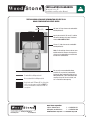
1
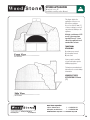
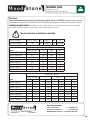
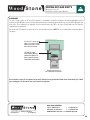
Installation and
Operation Manual
MT. CHUCKANUT
MOUNTAIN SERIES
Stone Hearth Oven
Gas-Fired European Models
WS-MS-4-(RFG, RFG-IR)-(W)-CE
MT. ADAMS
WS-MS-5-(RFG, RFG-IR)-(W)-CE
MT. BAKER
WS-MS-6-(RFG, RFG-IR)-(W)-CE
MT. RAINIER
WS-MS-7-(RFG, RFG-IR)-(W)-CE
wood stone corporation
1801 w. bakerview rd.
bellingham, wa 98226 usa
woodstone-corp.com
t.+1.360.650.1111
f.+1.360.650.1166
Revised May 2014
Doc no: M0037.01
TABLE OF CONTENTS
Mountain Series CE
Installation and Operation Manual
TABLE OF CONTENTS
MOUNTAIN SERIES���������������������������������������������������3
CAUTIONS & WARNINGS �����������������������������������������4
UNLOADING AND MOVING���������������������������������������5
INSTALLATION CLEARANCES �����������������������������������6
UNLOADING AND MOVING���������������������������������������8
MANTLE MOUNTING �����������������������������������������������9
FRONT PANEL ASSEMBLY��������������������������������������10
EXTENSION PANEL ASSEMBLY�������������������������������11
STUCCO APPLICATION�������������������������������������������13
UTILITIES���������������������������������������������������������������14
TECHNICAL DATA���������������������������������������������������15
OVEN VENTING �����������������������������������������������������16
FLUE ADAPTER �����������������������������������������������������17
VENTING DO’S AND DON’TS�����������������������������������18
CONTROLLER (RFG-IR)�������������������������������������������24
CONTROLLER (RFG)�����������������������������������������������25
INITIAL START-UP (RFG-IR)�������������������������������������27
OPERATION (RFG-IR) ���������������������������������������������28
INITIAL START-UP (RFG)�����������������������������������������30
OPERATION (RFG) �������������������������������������������������31
MAINTENANCE �����������������������������������������������������32
WOOD BURNING���������������������������������������������������33
PERIODIC THERMAL CLEANING �����������������������������34
OPERATIONAL SEQUENCE �������������������������������������35
ELECTRICAL DIAGRAM (RFG-IR)�����������������������������36
ELECTRICAL DIAGRAM (RFG)���������������������������������37
LIMITED WARRANTY ���������������������������������������������38
An ongoing program of product improvement may require us to change
specifications without notice. WS-MS-(RFG, RFG-IR)-CE,
Revised May 2014
Doc no: M0037.01
2
wood stone corporation
1801 w. bakerview rd.
bellingham, wa 98226 usa
t.+1.360.650.1111
f.+1.360.650.1166
[email protected] or visit woodstone-corp.com
MOUNTAIN SERIES
MOUNTAIN SERIES
Mountain Series CE
Installation and Operation Manual
INSTALLATION AND OPERATION MANUAL FOR WOOD STONE
WS-MS-(4, 5, 6, 7)-(RFG-IR, RFG)-(W)-CE-(NG, LP)
EUROPEAN MODEL
STONE HEARTH OVENS
NATURAL GAS OR LIQUID PROPANE FUELED
!
This appliance is for professional use by qualified personnel. This appliance must be
installed by qualified persons in accordance with the regulations in force. This appliance
must be installed with sufficient ventilation to prevent the occurrence of unacceptable
concentrations of substances harmful to health in the room in which it is installed. This
appliance needs an unobstructed flow of fresh air for satisfactory combustion and must
be installed in a suitably ventilated room in accordance with current regulations. This
appliance should be serviced by qualified personnel at least every 12 months, or sooner
if heavy use is expected.
An ongoing program of product improvement may require us to change
specifications without notice. WS-MS-(RFG, RFG-IR)-CE,
Revised May 2014
Doc no: M0037.01
wood stone corporation
1801 w. bakerview rd.
bellingham, wa 98226 usa
t.+1.360.650.1111
f.+1.360.650.1166
[email protected] or visit woodstone-corp.com
3
CAUTIONS & WARNINGS
Mountain Series CE
Installation and Operation Manual
WOOD STONE MOUNTAIN SERIES GAS-FIRED OVEN OPERATING INSTRUCTIONS
DO NOT THROW THIS MANUAL AWAY
RETAIN THIS MANUAL FOR FUTURE REFERENCE
Additional copies of this manual at woodstone-corp.com.
For prompt responses to service/maintenance questions, call your distributor.
READ ALL INSTRUCTIONS BEFORE INSTALLING AND USING THIS APPLIANCE
Please read this entire manual before you install the oven. Failure to follow instructions may result in property
damage, bodily injury or even death. Contact your local building or fire officials about restrictions and installation
inspection in your area.
FOR YOUR SAFETY: Consult your local gas supplier for a statement outlining a procedure to be followed in the event
you smell gas. Post the statement in a prominent location.
FOR YOUR SAFETY: Do not store or use gasoline or other flammable vapors or liquids in the vicinity of this or
any other appliance. Also, always keep the area under and around this appliance free and clear of any and all
combustible materials.
IMPORTANT: It is recommended that this oven be installed, maintained and serviced by authorized professionals.
WARNING: Improper installation, adjustment, alteration, service or maintenance can result in property
damage, injury or death. Read the installation, operation and maintenance instructions thoroughly before
installing or servicing this equipment.
Wood Stone’s gas-fired ovens have been tested and approved by
Intertek Testing Services and are listed to BS EN 203-1: 2005.
0359
An ongoing program of product improvement may require us to change
specifications without notice. WS-MS-(RFG, RFG-IR)-CE,
Revised May 2014
Doc no: M0037.01
4
wood stone corporation
1801 w. bakerview rd.
bellingham, wa 98226 usa
t.+1.360.650.1111
f.+1.360.650.1166
[email protected] or visit woodstone-corp.com
UNLOADING AND MOVING
UNLOADING AND MOVING
Mountain Series CE
Installation and Operation Manual
LIFTING THE OVEN
1. USING A CRANE
The oven arrives with four lifting eyes attached. When craning a Wood Stone oven,
use a spreader bar with a two-legged sling rigged on each end. The spreader
bar should be of a sufficient length to keep the sling from contacting the oven.
NOTE: Once lifting eyes are no longer needed, remove the lifting eyes one at a
time AND BE SURE TO REPLACE THE BOLTS THAT ATTACH THE OVEN TO THE
STAND.
Make fast (straps or chains
should not be allowed to slip)
Lifting eyes
2. USING A FORKLIFT
Be sure to use a forklift rated, and forks the minimum length, as shown in the
table below. If necessary, fork extensions must be used so the forks extend
through the fork lift pockets to the opposite side of the stand. Lift from either side
as shown. Do not lift from the front or back. The oven is very top heavy, so spread
the forks as far apart as possible.
Model
WS-MS-4
WS-MS-5
WS-MS-6
WS-MS-7
Oven
Mt. Chuckanut
Mt. Adams
Mt. Baker
Mt. Rainier
Approximate
ship weight
1,000 Kg.
1,500 Kg
1,900 Kg
2,400 Kg
Minimum
fork length
required
1.2 m (4')
1.5 m (5')
1.8 m (6')
2.1 m (7')
Required
forklift
capacity
2,000 Kg
3,000 Kg
3,000 Kg
4,000 Kg
3. USING A PALLET JACK
Once the oven has been removed from the delivery vehicle, it can easily be moved
on flat surfaces using a pallet jack. To lift the oven with a pallet jack, remove the
front and rear angle iron stabilizers from the base of the oven stand and place a
stout 4x4 post through the fork pocket as shown.
THE OVEN IS VERY TOP-HEAVY. MOVING THE OVEN UP OR DOWN A RAMP OR
INCLINE ON A PALLET JACK IS NOT SAFE!
4x4 post
DO NOT TURN THE OVEN ON ITS SIDE!
Moving a Wood Stone oven can present challenges to even the most experienced riggers. Secure the proper equipment and make
safety your first priority. Please don’t hesitate to call your distributor for technical support.
An ongoing program of product improvement may require us to change
specifications without notice. WS-MS-(RFG, RFG-IR)-CE,
Revised May 2014
Doc no: M0037.01
wood stone corporation
1801 w. bakerview rd.
bellingham, wa 98226 usa
t.+1.360.650.1111
f.+1.360.650.1166
[email protected] or visit woodstone-corp.com
5
INSTALLATION CLEARANCES
INSTALLATION CLEARANCES
Mountain Series CE
Installation and Operation Manual
IF THIS OVEN IS NOT PROPERLY INSTALLED A FIRE MAY RESULT. TO REDUCE THE RISK OF FIRE, FOLLOW THESE
INSTALLATION INSTRUCTIONS. A MAJOR CAUSE OF OVEN RELATED FIRES IS FAILURE TO MAINTAIN REQUIRED
CLEARANCES (AIR SPACES) TO COMBUSTIBLE MATERIALS. IT IS OF UTMOST IMPORTANCE THAT THIS OVEN BE
INSTALLED ONLY IN ACCORDANCE WITH THESE INSTRUCTIONS.
!
WARNING: Installation and servicing of this product could expose you to glasswool/ceramic
fibers as well as calcium silicate dust. ALWAYS WEAR RESPIRATORY AND EYE PROTECTION
WHEN INSTALLING OR SERVICING THIS APPLIANCE. Please read this entire manual before
you install the oven. Failure to follow instructions may result in property damage, bodily
injury or even death. Contact your local building or fire officials about restrictions and
installation inspection in your area.
CLEARANCES
a. Wood Stone gas-fired oven should have a minimum 25 mm (1") clearance to combustibles from all sides, and
356 mm clearance to combustibles from the top. If building a facade that will contact the oven, use completely noncombustible materials*. Please note that standard Drywall (or Sheetrock) is considered a combustible. Stucco equipped
ovens must have a minimum 25 mm (1") thick application of non-combustible stucco cement applied to the body of the
oven.
b. Any facade materials 152 mm (6") to either side of the oven doorway and above must be constructed of non-combustible
building materials.
c. Install this oven only on noncombustible floors.
* When noncombustible building materials contact the body of the oven, the respective clearances are transferred to those noncombustibles.
An ongoing program of product improvement may require us to change
specifications without notice. WS-MS-(RFG, RFG-IR)-CE,
Revised May 2014
Doc no: M0037.01
6
wood stone corporation
1801 w. bakerview rd.
bellingham, wa 98226 usa
t.+1.360.650.1111
f.+1.360.650.1166
[email protected] or visit woodstone-corp.com
INSTALLATION CLEARANCES
Mountain Series CE
Installation and Operation Manual
THE FOLLOWING CLEARANCE INFORMATION APPLIES TO ALL
WOOD STONE MOUNTAIN SERIES OVENS
356 mm (14") top clearance to combustible
building materials.
356 mm (14")
Any facade materials 152 mm (6") to either
side of the doorway of the oven and above
must be NON-COMBUSTIBLE.
25 mm (1") side clearance to combustible
building materials.
Note: 0" side and top clearance to non-combustible materials. However, the respective
clearances to combustibles are transferred
to those non-combustibles.
For use only on noncombustible floors
(installér sur un plancher incombustible
seulement). Non-combustible floor surface
AND provided with a non-combustible floor
covering at least 30" to each side of, and
36" in front of the door opening.
Combustible building material
Non-combustible building material
Any facade wall 152mm (6") to either side
of the oven doorway and above MUST be
of non-combustible construction with no
exceptions.
An ongoing program of product improvement may require us to change
specifications without notice. WS-MS-(RFG, RFG-IR)-CE,
Revised May 2014
Doc no: M0037.01
wood stone corporation
1801 w. bakerview rd.
bellingham, wa 98226 usa
t.+1.360.650.1111
f.+1.360.650.1166
[email protected] or visit woodstone-corp.com
7
ASSEMBLY INSTRUCTIONS
UNLOADING AND MOVING
Mountain Series CE
Installation and Operation Manual
ASSEMBLY
1. Mount the oven mantle (if provided) directly below the doorway and flush with the floor using the hardware provided.
2. Mount the stainless steel toe kick to the front of the oven stand, near the floor using the hardware provided.
3. Mount the service/intake panel to the brackets on the front of the stand, directly below the doorway, using the hardware
provided.
a. Do not obstruct the flow of combustion and ventilation air between the toe kick and the bottom of the service/
intake panel.
b. This panel is the only access for servicing the gas and electrical components of the oven so it must be left
accessible and removable.
An ongoing program of product improvement may require us to change
specifications without notice. WS-MS-(RFG, RFG-IR)-CE,
Revised May 2014
Doc no: M0037.01
8
wood stone corporation
1801 w. bakerview rd.
bellingham, wa 98226 usa
t.+1.360.650.1111
f.+1.360.650.1166
[email protected] or visit woodstone-corp.com
MANTLE MOUNTING
MANTLE MOUNTING
Mountain Series CE
Installation and Operation Manual
The initial steps are the same for mounting either a stainless mantle or a bracket for a granite mantle.
1. Begin by installing the threaded studs into
the clip nuts below the oven doorway (3 or 4
turns is sufficient).
2. Position the mantle (or bracket) on the oven,
making sure the rear flange rests on the
floor of the oven (you may need an extra pair
of hands).
3. Place one stainless steel washer and a cap
nut onto each stud. Tighten the cap nuts so
the mantle is securely held in place.
4. Using the high temperature silicone
(provided), fill any gaps between the oven
hearth and the mantle flange. Gaps between
the mantle flange and the stainless steel
doorway frame may also need to be filled
with a small amount of the silicone sealant.
Clean up any sealant before it dries.
INSTALLATION OF GRANITE
After completing the steps outlined above, apply a generous amount of silicone adhesive (provided) to the top of the steel mantle
bracket.
Put the stone in place and apply light
pressure to seat it properly. Make sure that
the angle in the granite lines up with the
angle in the bracket. Allow the sealant to
set for several hours before filling any gap
between the stone slab and the metal bracket
with the silicone sealant (provided). Clean up
any sealant before it dries.
An ongoing program of product improvement may require us to change
specifications without notice. WS-MS-(RFG, RFG-IR)-CE,
Revised May 2014
Doc no: M0037.01
wood stone corporation
1801 w. bakerview rd.
bellingham, wa 98226 usa
t.+1.360.650.1111
f.+1.360.650.1166
[email protected] or visit woodstone-corp.com
9
FRONT PANEL ASSEMBLY
FRONT PANEL ASSEMBLY
Mountain Series CE
Installation and Operation Manual
STANDARD FRONT PANEL AND TOE KICK ASSEMBLY INSTRUCTIONS
Flame Height Control Knob
D
Controller
B
D
C
D
C
B
D
D
D
D
A
Service Panel
D
A
Transformer Box
Contains terminal strip for incoming power supply.
NOTE: Have licensed electrician make this electrical connection
A Hex-head self-tapping screw. Used to attach
toe kick. 4 total.
B Phillips head 1/4-20 screw. Used to attach
service panel to controller bracket. 2 total.
C Phillips head #10 screw. Used to attach service
panel to throttle knob bracket. 2 total.
D Phillips head self-tapping screw. Used to
secure the sides of the service panel. 8 total.
Service panel throttle assembly
The throttle knob position can be
adjusted inward or outward by
loosening the clamp and sliding the
throttle knob assembly to the desired
position. Be sure to retighten the clamp
once the throttle knob is in the desired
position.
An ongoing program of product improvement may require us to change
specifications without notice. WS-MS-(RFG, RFG-IR)-CE,
Revised May 2014
Doc no: M0037.01
10
Throttle valve
Service panel throttle assembly
Clamp
Throttle bracket
Cotter pin
EMT throttle rod
extension
Cotter key
wood stone corporation
1801 w. bakerview rd.
bellingham, wa 98226 usa
Pointer
collar/
Pointer
Flame Height
Control Knob
t.+1.360.650.1111
f.+1.360.650.1166
[email protected] or visit woodstone-corp.com
EXTENSION PANEL ASSEMBLY
Mountain Series CE
Installation and Operation Manual
OPTIONAL LOWER EXTENSION, THROTTLE ROD AND CONTROLLER ASSEMBLY INSTRUCTIONS
1. After the oven has been leveled, remove
the throttle rod assembly which has been
attached to the inside of the stand for
shipping. Position the lower extension
assembly onto the front of the oven. It
will rest on the guides that are welded to
the oven legs. Attach the assembly to the
oven legs using the 1/4-20 nuts, bolts and
washers.
2. Remove the access panel.
Throttle Valve
Extension panel
throttle assembly
Throttle bracket
(already attached)
Cotter pin
EMT throttle
rod extension
Clamp
3. Attach the controller to
the mounting bracket of
the extension using the
1/4-20 bolts provided.
Pointer collar /
Pointer assembly
Flame Height
Control Knob
4. Remove the throttle knob/pointer section from the throttle assembly. Slip the clamp off of the throttle knob assembly
and slide it over the EMT throttle rod extension. Slip the front of the EMT throttle rod through the throttle rod bracket
at the front of the oven, then slip the other end of the EMT onto the throttle valve at the back of the oven. Note: The
end of the EMT that goes over the throttle valve is drilled to accept a cotter pin. Attach the EMT throttle rod extension
to the throttle valve using the cotter pin and open the end of the pin slightly to prevent it from falling out. Make
certain the valve is in the full open position by turning the attached throttle rod extension counterclockwise
until it stops.
Continued
An ongoing program of product improvement may require us to change
specifications without notice. WS-MS-(RFG, RFG-IR)-CE,
Revised May 2014
Doc no: M0037.01
wood stone corporation
1801 w. bakerview rd.
bellingham, wa 98226 usa
t.+1.360.650.1111
f.+1.360.650.1166
[email protected] or visit woodstone-corp.com
11
EXTENSION PANEL ASSEMBLY
Mountain Series CE
Installation and Operation Manual
OPTIONAL LOWER EXTENSION, THROTTLE ROD AND CONTROLLER ASSEMBLY INSTRUCTIONS
5. Pass the throttle rod through the throttle bracket (already attached). Position the pointer
in approximately the 2 o’clock position. Slide the clamp on the EMT over the end of the
throttle rod/knob assembly and Attach the throttle rod to the EMT throttle rod extension
using the compression clamp. On curved façade extensions, make to leave at least 3
mm (1/8") of space between the end of the pointer and the bracket when it is set to a
horizontal position.
6. Reinstall the front panel. Secure the controller with a 1/4-20 screw at the top and bottom.
Use (2) #10 stainless steel sheet metal screws to secure the front panel to the throttle
bracket.
7. CALIBRATING THE POINTER
Loosen the pointer collar set screws using a 3/16" Allen wrench.
Position the attached pointer to “5” on the Flame Height Index
Scale. Tighten the pointer collar in this position. Make certain
the tip of the pointer is at least 3 mm (1/8") away from the index
scale at the tightest point of the rotation of the knob so it does
not scrape.
3 mm (1/8")
minimum clearance
Pointer collar set screws
An ongoing program of product improvement may require us to change
specifications without notice. WS-MS-(RFG, RFG-IR)-CE,
Revised May 2014
Doc no: M0037.01
12
wood stone corporation
1801 w. bakerview rd.
bellingham, wa 98226 usa
t.+1.360.650.1111
f.+1.360.650.1166
[email protected] or visit woodstone-corp.com
STUCCO APPLICATION
STUCCO APPLICATION
Mountain Series CE
Installation and Operation Manual
This figure depicts the
application of stucco on a
Wood Stone appliance.
Use no less than 25 mm (1")
of stucco coating to cover all
exposed metal lathing on the
appliance.
Maintain a minimum of 152
mm (6") clearance from
top and 25 mm (1") from
side of the appliance to all
combustible surfaces.
TRADITIONAL
STUCCO MIX
1 part masonry cement
1 part regular cement
5 parts sand
Stucco premix is available
at your local lumber yard or
building supply store.
Follow stucco manufacturer’s
instructions for correct mixing
information.
MINIMUM STUCCO
APPLICATION IS 25 mm
(1")
An ongoing program of product improvement may require us to change
specifications without notice. WS-MS-(RFG, RFG-IR)-CE,
Revised May 2014
Doc no: M0037.01
wood stone corporation
1801 w. bakerview rd.
bellingham, wa 98226 usa
t.+1.360.650.1111
f.+1.360.650.1166
[email protected] or visit woodstone-corp.com
13
UTILITIES
Mountain Series CE
Installation and Operation Manual
GAS
!
DO NOT USE FLAME TO TEST FOR LEAKS
Wood Stone Gas ovens are equipped with a 3/4" (19 mm) female ISO-7 gas connection. Have a licensed gas installer
provide the hookup and test all fittings and pipe connections for leaks. Use approved gas leak detectors (soap
solutions or equivalent) over and around the fittings and pipe connections.
SV-1 AND SV-2 ARE THE GAS CONTROL VALVES THAT OPERATE THE UNDERFLOOR INFRARED BURNER AND
THE INTERIOR RADIANT BURNER, RESPECTIVELY.
NOTE: RFG models are only equipped with the SV-2 valve. SV-1 is located directly behind the service/ intake panel
and in front of the underfloor IR burner. SV-2 is located under the oven to the rear left.
The manifold pressure test port for the underfloor IR burner (served by SV-1) is a plugged nipple tap located near
the left end of the burner manifold. The manifold pressure test port for the radiant burner (served by SV-2) is a
plugged nipple tap located at the base of the T-junction between the SV-2 and the radiant/interior burner. Both
gas valves (SV-1 and SV-2) have an additional plugged nipple tap on the inlet side. The burner manifold pressures
have been adjusted and tested at the factory.
Wood Stone recommends that the oven be equipped with an individual shutoff valve and that this individual
shutoff valve (supplied by others) be left easily accessible. Wood Stone also recommends that inspection and
maintenance of the burners and gas piping connections of this appliance be performed at regularly scheduled
intervals and only by professional gas appliance service agencies.
SCOPE OF APPROVALS
NATURAL GAS (METHANE)
G20 @ 20mbar - I2H(20) for use in:
AT, BG, CZ, DK, EE, FI, GR, HR, HU, IS, IE, IT, LV, LT, NO, PT, RO, SK, SI, ES, SE, CH, TR and GB
I2E(20/25) for use in: DE, LU and PL
|2E+(20/25) for use in: Be and Fr
I2L(25) for use in: NL
I2HS(25) for use in: HU
PROPANE AND PROPANE BLENDS
I3P(37) for use in: FI, DE, GR, IE, HR, LU, NL, PL, SK, SI, ES, CH, TR and GB
I3P(50) for use in: CY, CZ, MT and SK
I3+(28-30,37) for use in: BE, CY, CZ, EE, FR, GR, IE, IT, LT, LU, LV, PT, RO, SK, ES, CH and GB
I3B/P(30) for use in: BG, CY, CZ, DK, EE, FI, GR, HR, LV, LT, LU, MT, NL, NO, SK, SI, SE and TR
I3B/P(37) for use in: PL
I3B/P(50) for use in: AT, DE, HU, SK and CH
An ongoing program of product improvement may require us to change
specifications without notice. WS-MS-(RFG, RFG-IR)-CE,
Revised May 2014
Doc no: M0037.01
14
wood stone corporation
1801 w. bakerview rd.
bellingham, wa 98226 usa
t.+1.360.650.1111
f.+1.360.650.1166
[email protected] or visit woodstone-corp.com
TECHNICAL DATA
Mountain Series CE
Installation and Operation Manual
ELECTRICAL
Have a licensed electrician connect the transformer terminal strip to a 230 VAC, 5 A circuit. Electrical diagrams
are located on the back of the removable service/air intake panel of the appliance and also at the end of this manual.
PROVIDE DISCONNECT DEVICE: This appliance must be provided with an all-pole type disconnect device in the incoming
power supply so that the appliance can be completely isolated from the power supply.
!
THIS APPLIANCE MUST BE ELECTRICALLY GROUNDED.
EN 437 Gas Group
Inlet Pressure (mbar)
|2H, |2E, |2L ,I2ELL
|2L
|3B/P, |3+
|B/P
|3P
20
25
28-30/37
50
30/37/50
Declared Input (kW)
Model
|2H, |2L, |2E, I2ELL
|3+
|3B/P
|3P
20
33.7
30.8
55.1
30.8
55.1
36
64.5
17.6
29.9
27.5
46.6
27.5
46.6
41.6
66.5
17.6
29.9
27.5
46.6
27.5
46.6
41.6
66.5
17.6
29.9
27.5
46.6
27.5
46.6
41.6
66.5
WS-MS-4-RFG-CE
WS-MS-4-RFG-IR-CE
WS-MS-5-RFG-CE
WS-MS-5-RFG-IR-CE
WS-MS-6-RFG-CE
WS-MS-6-RFG-IR-CE
WS-MS-7-RFG-CE
WS-MS-7-RFG-IR-CE
Valve Outlet Pressure
|2H, |2L, |2E, I2ELL
Model
WS-MS-4-RFG-CE
WS-MS-4-RFG-IR-CE
WS-MS-5-RFG-CE
WS-MS-5-RFG-IR-CE
WS-MS-6-RFG-CE
WS-MS-6-RFG-IR-CE
WS-MS-7-RFG-CE
WS-MS-7-RFG-IR-CE
SV-1
8.7
8.7
8.7
8.7
SV-2
12.4
12.4
11.8
11.8
11.8
11.8
11.5
11.5
An ongoing program of product improvement may require us to change
specifications without notice. WS-MS-(RFG, RFG-IR)-CE,
Revised May 2014
Doc no: M0037.01
|3+
SV-1
17.5
17.5
17.5
17.9
|3B/P
SV-2
13.6
13.6
15.6
15.6
15.6
15.6
18.4
18.4
SV-1
17.5
17.5
17.5
17.9
|3P
SV-2
13.6
13.6
15.6
15.6
15.6
15.6
18.4
18.4
wood stone corporation
1801 w. bakerview rd.
bellingham, wa 98226 usa
SV-1
22.4
22.4
22.4
22.9
SV-2
17.4
17.4
20
20
20
20
22.7
22.7
t.+1.360.650.1111
f.+1.360.650.1166
[email protected] or visit woodstone-corp.com
15
OVEN VENTING
OVEN VENTING
Mountain Series CE
Installation and Operation Manual
Wood Stone ovens should be vented in accordance with pertinent national, regional and local codes concerning such appliances;
check venting plans with the authority having jurisdiction before proceeding with installation.
The above statement taking precedence, Wood Stone Corporation recommends the following two venting options:
1. The Wood Stone MS Series ovens can be vented as a Type A appliance (with no flue connection), designed to be installed
under an exhaust hood (canopy). The hood must be a Type 1 (grease rated) hood connected to a (grease rated) duct system.
The venting system must be designed and installed in accordance with all relevant codes pertaining to grease and smoke
producing commercial cooking appliances. Ovens that utilize solid fuel must be vented separately from any non-solid fuel
burning appliances. There may be requirements for interlocking the oven or its gas supply with the ventilation system. Check
with your local code official. Airflow should be adjusted according to the requirements specified by the hood manufacturer
and/or local codes.
OR
2. The oven is also approved as a Type B11 appliance, designed to be connected directly to a chimney which is installed in
accordance with all relevant local and national codes. The chimney system must be installed and constructed to the same
requirements as a duct that serves grease and smoke producing commercial cooking appliances. If venting the oven with this
method, the oven must be vented independently of other equipment. A suitable fan should be used at the end of the duct run
to ensure proper draft in all conditions. Wood Stone does not recommend using an in-line type fan. When installed, the fan
speed/air flow should be adjusted to attain the appropriate duct pressure at the oven flue collar:
DUCT PRESSURE
For gas-fired ovens without solid fuel: 0.25 mbar, (0.1" W.C.)
For any oven utilizing solid fuel: 0.35 mbar, (0.14" W.C.)
This pressure may be checked by inserting the pressure test probe up through the oven doorway to the point where the
duct is connected to the oven flue collar.
FAN TEMPERATURE RATING
The fan must also be of a suitable temperature rating.
For gas-fired ovens without solid fuel the fan must be rated for a minimum of 150 °C (300 °F) continuous.
INTERLOCK SYSTEM
There may be requirements for interlocking the oven or its gas supply with the ventilation system. Check with your local
code official.
An ongoing program of product improvement may require us to change
specifications without notice. WS-MS-(RFG, RFG-IR)-CE,
Revised May 2014
Doc no: M0037.01
16
wood stone corporation
1801 w. bakerview rd.
bellingham, wa 98226 usa
t.+1.360.650.1111
f.+1.360.650.1166
[email protected] or visit woodstone-corp.com
FLUE ADAPTER
FLUE ADAPTER
Mountain Series CE
Installation and Operation Manual
MOUNTAIN SERIES OVENS: FLUE ADAPTER
The flue adapter unit is designed to facilitate connection to a round duct. Use the stainless steel screws and sealant provided to
attach the flue adapter to the exhaust outlet on the oven if it is not already installed. Note: MS-4 ovens come standard with a round
203mm (8") collar and do not require the flue adapter for a direct connection.
Note: If using a Selkirk or other modular-type duct, attach according to the manufacturer’s instructions. Otherwise, the duct must
be attached with a full perimeter weld. All duct must be grease-rated duct. If the oven is going to be enclosed, the flue adapter and
exhaust outlet must be wrapped with an insulating material approved for use with a grease-duct.
Flue adapter
Flue adapter attached
to oven flue collar
If the oven is to be enclosed, wrap with an
approved insulation.
An ongoing program of product improvement may require us to change
specifications without notice. WS-MS-(RFG, RFG-IR)-CE,
Revised May 2014
Doc no: M0037.01
wood stone corporation
1801 w. bakerview rd.
bellingham, wa 98226 usa
t.+1.360.650.1111
f.+1.360.650.1166
[email protected] or visit woodstone-corp.com
17
VENTING DO'S AND DONT'S
VENTING DO’S AND DON’TS
Mountain Series CE
Installation and Operation Manual
VENTING DO’S AND DON’TS
When installing a Wood Stone Mountain Series oven there are some basic guidelines to follow regarding oven venting that will help
ensure proper operation and performance of the gas burners on the oven. These guidelines will also help prevent damage to the
oven's gas and electrical components due to improper venting and installation. Damage caused by improper venting and installation
is not covered by the oven warranty. This information applies to all Wood Stone Mountain Series (MS) ovens equipped with 1 or
more gas burners.
Most Wood Stone Mountain Series ovens are built into some sort of wall structure or enclosure. This creates the potential for
different venting scenarios that can be detrimental to the operation and performance of the oven burners. Here are some basic
rules that to follow that will ensure a properly functioning oven installation. Illustrated examples are included on the following pages.
RULE 1
The ONLY pathway for air to enter the space beneath the oven should be at the front of the oven at the perforated opening in the
oven service panel provided with the oven, or on ovens equipped with an optional storage box, through the perforations provided
on the oven storage box. This will eliminate the chance of air movement or cross drafts beneath the oven that can disrupt the oven
burners.
RULE 2
DO NOT block the flow of air through the front service panel. It is required to provide necessary combustion air to the oven burners.
Airflow and service access MUST be provided from the front of the oven only at this service panel. DO NOT relocate the oven air
intake (see Rule 1).
RULE 3
To ensure proper venting of the oven, you must use an appropriate exhaust fan as described in this manual. There must also be
an adequate source of make-up air provided to your kitchen space (the room that the oven opens into). The make-up air supply
should not point directly at the oven. Other than the oven service panel, do not provide make-up air or other ventilation into an
enclosure that surrounds the oven (see Rule 1). Without proper make-up air the oven, (or any gas equipment) will not vent and
operate correctly.
Please see drawings on the following pages.
An ongoing program of product improvement may require us to change
specifications without notice. WS-MS-(RFG, RFG-IR)-CE,
Revised May 2014
Doc no: M0037.01
18
wood stone corporation
1801 w. bakerview rd.
bellingham, wa 98226 usa
t.+1.360.650.1111
f.+1.360.650.1166
[email protected] or visit woodstone-corp.com
VENTING DO’S AND DONT’S
Mountain Series CE
Installation and Operation Manual
DIRECT CONNECT VENTING EXAMPLES
Equal air pressure inside and
outside of oven room
Stud wall
Facade
surface
Air intake area
on removable
service panel
properly
exposed
Exhaust
flow
direction
is normal
Example 1 shows a proper installation.
Enclosure around the oven is completely
sealed so that the only air entering the space
beneath the oven comes through the oven
service panel.
Intake air flows
through designed
intake vents in the
service panel to
oven burners
1 Acceptable venting
Equal air pressure
inside and outside of
oven room
Facade material
improperly placed
over oven air
intake
Exhaust
flow
direction is
normal
Example 2 is not acceptable because the
combustion air intake is blocked, preventing
combustion air from reaching the oven
burners. The burners will not function properly,
and this will also lead to damage of oven
components.
Insufficient
combustion air
resulting in burner
problems & poor
oven performance
2 Unacceptable venting
An ongoing program of product improvement may require us to change
specifications without notice. WS-MS-(RFG, RFG-IR)-CE,
Revised May 2014
Doc no: M0037.01
wood stone corporation
1801 w. bakerview rd.
bellingham, wa 98226 usa
t.+1.360.650.1111
f.+1.360.650.1166
[email protected] or visit woodstone-corp.com
19
VENTING DO’S AND DONT’S
Mountain Series CE
Installation and Operation Manual
HOOD INSTALLATIONS
In addition to the information given for installations using the direct connect venting method, the following information applies to
installations where the oven is being vented using a Type 1 hood. Also refer to the OVEN VENTING section earlier in this manual.
PROPER MOUNTING POSITION FOR THE WOOD STONE HOOD
1. Center the hood from side to side on the oven. Note that in an MS-5, 6 or 7 model, the oven has the round flue adapter
attached. The adapter may prevent the proper positioning of the hood. The flue adapter is attached with screws. (The MS-4
does not require an adapter.) Simply remove the screws to remove the adapter if it is in the way.
2. Pull the hood forward so that the notch, as viewed from the side of the hood, lines up with the front edge of the top of the
oven.
3. Secure the hood to the top of the oven using #10 self tapping screws. The flanges on the hood are pre-drilled. Screw directly
into the top of the oven to secure the hood.
4. Attach grease-rated duct to the outlet on the hood. The hood captures over the oven flue collar and oven doorway. No
connection is made to the oven flue collar.
Continued on next page
An ongoing program of product improvement may require us to change
specifications without notice. WS-MS-(RFG, RFG-IR)-CE,
Revised May 2014
Doc no: M0037.01
20
wood stone corporation
1801 w. bakerview rd.
bellingham, wa 98226 usa
t.+1.360.650.1111
f.+1.360.650.1166
[email protected] or visit woodstone-corp.com
VENTING DO’S AND DONT’S
Mountain Series CE
Installation and Operation Manual
HOOD INSTALLATION WITH DECORATIVE FACADE WALL/OVEN ENCLOSURE
For installations where a hood is being used with a decorative facade wall or oven enclosure, it will be necessary to both seal the
gap between the facade wall and the top of the oven, and the gaps at the sides of the hood between the facade wall and the front
of the oven. This will prevent air from being pulled up the sides of the oven from below by the hood. It will also prevent debris, etc.
from falling into the facade wall.
Flashing piece
by installer
Acceptable venting
Additional flashing detail
Wall stud
Shield
flashing
to be
flush
with
top of
oven
Note that the hood does extend out beyond the face of the
oven. DO NOT extend the oven facade wall into the oven
hood. The wall beneath the hood must stop at the top of the
oven. To allow for proper function of the hood, filter removal
and hood maintenance you must provide a minimum of
203mm (8") of clearance between the front face of the
facade wall and the front of the hood.
Acceptable venting
An ongoing program of product improvement may require us to change
specifications without notice. WS-MS-(RFG, RFG-IR)-CE,
Revised May 2014
Doc no: M0037.01
Continued on next page
wood stone corporation
1801 w. bakerview rd.
bellingham, wa 98226 usa
t.+1.360.650.1111
f.+1.360.650.1166
[email protected] or visit woodstone-corp.com
21
VENTING DO’S AND DONT’S
Mountain Series CE
Installation and Operation Manual
Incorrect installation. No flashing installed
so air being pulled up the sides of the oven
from beneath.
Unacceptable venting
Exhaust stack
Stud wall
Side view of
properly installed hood
Hood
Airflow
shield
Facade
surface
Acceptable venting
An ongoing program of product improvement may require us to change
specifications without notice. WS-MS-(RFG, RFG-IR)-CE,
Revised May 2014
Doc no: M0037.01
22
wood stone corporation
1801 w. bakerview rd.
bellingham, wa 98226 usa
t.+1.360.650.1111
f.+1.360.650.1166
[email protected] or visit woodstone-corp.com
VENTING DO’S AND DONT’S
Mountain Series CE
Installation and Operation Manual
CLEARANCES
The Type 1 hood requires an 457 mm (18") clearance to combustible construction. Clearances to limited combustibles may be
reduced per NFPA 96 and/or your local codes. Approved clearance reduction methods may also be used, per NFPA 96 and/or your
local codes. (These reductions are applicable to the hood and/or duct only, NOT to the oven.) Consult with your local inspector
regarding approved methods.
Any facade wall 152 mm (6") to either side of the oven doorway and above MUST be of non-combustible construction with no
exceptions.
457 mm (18") clearances for
hood, or in accordance with
hood manufacturer's instructions and/or local codes.
152 mm (6") from
either side of doorway
and the area above (as
shown) must be of noncombustible construction.
Shaded areas must be of
non-combustible construction.
All installations subject to the approval of the local authority having jurisdiction. Wood Stone recommends you submit
your venting plans in advance to your local authority for approval.
An ongoing program of product improvement may require us to change
specifications without notice. WS-MS-(RFG, RFG-IR)-CE,
Revised May 2014
Doc no: M0037.01
wood stone corporation
1801 w. bakerview rd.
bellingham, wa 98226 usa
t.+1.360.650.1111
f.+1.360.650.1166
[email protected] or visit woodstone-corp.com
23
CONTROLLER (RFG-IR)
RFG-IR OVEN CONTROLLER
Mountain Series CE
Installation and Operation Manual
RFG-IR CONTROLLER
Dome Flame
indicator light
Indicates the pilot
for the radiant flame
has lit.
Power indicator light
Indicates the oven is
turned ON.
Hearth Heat indicator light
Indicates that the pilot for the
underfloor IR burner is lit. This light
will go off whenever the hearth
temperature is above the Hearth
Set Point.
Hearth Temperature display
Displays temperature of
oven floor (hearth). Sensor is
embedded 1" below hearth
surface.
Arrow buttons
Pressing appropriate
directional arrow to
adjusts Hearth Set Point
temperature up or down.
Hearth Set Point display
Indicates set point
temperature of
underfloor IR burner
F
I
On/Off button
Press to turn oven on/off
O
1-360-650-1111
An ongoing program of product improvement may require us to change
specifications without notice. WS-MS-(RFG, RFG-IR)-CE,
Revised May 2014
Doc no: M0037.01
24
C
Temperature unit selector
Toggles between Fahrenheit
and Celsius temperature
scales in display screens
www.woodstone-corp.com
wood stone corporation
1801 w. bakerview rd.
bellingham, wa 98226 usa
t.+1.360.650.1111
f.+1.360.650.1166
[email protected] or visit woodstone-corp.com
CONTROLLER (RFG)
RFG OVEN CONTROLLER
Mountain Series CE
Installation and Operation Manual
TYPE 2 CONTROLLER
Used on RFG models shipped before August 2005. See next page for newer controller.
Dome Flame
indicator light
Indicates the pilot
for the radiant flame
has lit.
Power indicator light
Indicates the oven is
turned ON.
Hearth Temperature display
Displays temperature of
oven floor (hearth). Sensor is
embedded 1" below hearth
surface.
F
I
On/Off button
Press to turn oven on/off
O
1-360-650-1111
An ongoing program of product improvement may require us to change
specifications without notice. WS-MS-(RFG, RFG-IR)-CE,
Revised May 2014
Doc no: M0037.01
C
Temperature unit selector
Toggles between Fahrenheit
and Celsius temperature
scales in display screens
www.woodstone-corp.com
wood stone corporation
1801 w. bakerview rd.
bellingham, wa 98226 usa
t.+1.360.650.1111
f.+1.360.650.1166
[email protected] or visit woodstone-corp.com
25
CONTROLLER (RFG)
Mountain Series CE
Installation and Operation Manual
TYPE 4 CONTROLLER
Used on RFG ovens shipped after August 2005.
Temperature
units
Press and hold to
switch between
Fahrenheit
and Celsius.
Hearth Temperature
The hearth (floor)
temperature will
be displayed when
the oven is turned
on. Display will
read “LO” when the
temperature is below
38 °C (100 °F).
An ongoing program of product improvement may require us to change
specifications without notice. WS-MS-(RFG, RFG-IR)-CE,
Revised May 2014
Doc no: M0037.01
26
ON/OFF button
Press to turn
oven on and off.
wood stone corporation
1801 w. bakerview rd.
bellingham, wa 98226 usa
t.+1.360.650.1111
f.+1.360.650.1166
[email protected] or visit woodstone-corp.com
INITIAL START-UP (RFG-IR)
RFG-IR OVEN OPERATION
Mountain Series CE
Installation and Operation Manual
INITIAL OVEN START-UP PROCEDURE
IMPORTANT: If at any time you feel that either or both of the burners are not operating properly, turn the oven off and call for
service. Before servicing, disconnect the electrical supply at the breaker and turn off the gas supply at the appliance’s individual
gas shutoff valve. In the event of a power failure, no attempt should be made to operate the oven.
Your oven was cured at the factory. However in the course of shipment, storage on site, etc. the ceramic materials will have
absorbed moisture. It is critical that the procedure below be followed to ensure that this moisture is driven from the ceramic in a
controlled fashion. This will minimize cracking and prevent damage to the oven that could otherwise occur by bringing the oven to
temperature rapidly the first time it is used. This initial procedure need only be followed the first time the oven is fired and/or if the
oven has not been used for an extended period of time.
BEFORE GETTING STARTED
1. Make sure main gas supply is on (valve parallel with gas line).
2. Make sure that the venting system has been tested and approved for operation and is on.
FIRST DAY
1. Remove the Night Heat Retention Door(s). Push the ON/OFF button on controller. It may take awhile for the gas to purge all the
air from the gas lines.
2. Allow oven to operate at the factory settings for 1 hour (Hearth Set Point at 38 °:C (100 °F), radiant flame at its lowest setting).
Leave the Hearth Set Point at 38 °C (100° F) throughout the entire first day.
3. After one hour, raise radiant flame to 25% (~16 cm (6") flame, “2” on the Flame Height Index Scale) using the Flame Height
Control Knob. Hold this setting for 4 hours.
4. After 4 hours at 25% flame, raise to 50% flame (~20 cm (8") flame, “3” on the Flame Height Index Scale) using the Flame
Height Control Knob and hold for at least another 4 hours or until the temperature reaches 260 °C (500 °F).
5. Once the temperature reaches 260 °C (500 °F) the oven is ready for use. If you will be shutting the oven down, see the
instructions that follow.
TURNING OFF THE OVEN
1. Push ON/OFF button. All gas will go off. Put the Night Heat Retention Door(s) in place to retain heat.
NOTE: Always wait 5 minutes before restarting the oven. Never run the oven with the Night Heat Retention Door(s)in place.
NOTE: Small “crazing” cracks will occur with normal heating and cooling. They will not effect the performance or durability
of the oven. If cracks of 1/8" or more develop, contact Wood Stone for evaluation.
NEVER PLACE ANYTHING IN OR ABOVE THE RADIANT FLAME
An ongoing program of product improvement may require us to change
specifications without notice. WS-MS-(RFG, RFG-IR)-CE,
Revised May 2014
Doc no: M0037.01
wood stone corporation
1801 w. bakerview rd.
bellingham, wa 98226 usa
t.+1.360.650.1111
f.+1.360.650.1166
[email protected] or visit woodstone-corp.com
27
OPERATION (RFG-IR)
Mountain Series CE
Installation and Operation Manual
GENERAL DAILY OVEN OPERATION
END OF THE DAY
1. Push I/O button, all gas will go off, even the pilots.
2. Put oven door in place to retain heat.
BEGINNING OF THE DAY
1. Remove oven door
2. Push I/O button, set controller to desired floor temperature and turn the radiant flame to its highest setting. Oven should be
stabilized at or above the set point within an hour.
OVEN INTERIOR CLEANING
Wood Stone recommends the use of long-handled brushes for sweeping up surface debris that will accumulate on the floor of the
oven during use. Use a natural fiber brush—always brushing away from the radiant burner well. For deeper cleaning, use a brass
bristled brush. The oven floor can be then cleaned with a damp rag wrapped around the brass bristled brush head. (Wood Stone
offers an assortment of oven brushes available through your dealer. Specification sheets may be viewed on the Wood Stone website
under Tools & Accessories.)
HOW TO READ FLOOR TEMPERATURE
The floor temperature is continuously displayed by the controller in the upper window. This reading is being taken by a
thermocouple about an inch below the floor surface, so the actual surface temperature may be somewhat different, and
is best measured using a non-contact (IR) thermometer.
HOW TO ADJUST THE FLOOR TEMPERATURE (HEARTH SET POINT)
To adjust the oven's thermostatic floor temperature setting, simply press the arrow button corresponding to the direction
in which you would like the setting to go. If the thermostatic set point is raised above the actual hearth temperature, the
underfloor IR burner should activate.
!
NEVER PLACE ANYTHING IN OR ABOVE THE RADIANT FLAME
An ongoing program of product improvement may require us to change
specifications without notice. WS-MS-(RFG, RFG-IR)-CE,
Revised May 2014
Doc no: M0037.01
28
wood stone corporation
1801 w. bakerview rd.
bellingham, wa 98226 usa
t.+1.360.650.1111
f.+1.360.650.1166
[email protected] or visit woodstone-corp.com
OPERATION (RFG-IR)
Mountain Series CE
Installation and Operation Manual
DETAILED DAILY OVEN OPERATION FOR RFG-IR MODELS ONLY
IMPORTANT: If at any time you feel that either or both of the burners are not operating properly, turn the oven off and call for service.
Before servicing, disconnect the electrical supply at the breaker and turn off the gas supply at the appliance’s individual gas shutoff
valve. In the event of a power failure, no attempt should be made to operate the oven.
DAILY STARTUP
Press the I/O button to start the oven. The radiant burner will ignite. The infrared underfloor IR burner will ignite if the actual floor
temperature is below the set point temperature to which the controller is adjusted.
GREEN LIGHT: Indicates the system is energized.
GREEN LIGHT: Indicates the pilot flame for the radiant burner is lit.
GREEN LIGHT: Indicates that the pilot flame for the underfloor IR burner is lit.
This light will go off whenever the actual floor temperature is above the Hearth Set Point.
TURNING OFF THE OVEN
Push the I/O button on the controller to turn the oven off.
Both burners will go out and the digital readout on the controller will go out.
ADJUSTING THE RADIANT (DOME) FLAME
To adjust the radiant flame: The radiant flame is always on (when the oven is operating) and can be adjusted to any
flame intensity between its highest and lowest setting. Simply turn the knob located to the lower left of the doorway,
beneath the mantle. This burner is the primary heat source for the oven. The infrared under floor burner will act as an
assist, to maintain desired floor temperatures during periods of high food production.
ADJUSTING THE FLOOR SET-POINT
To adjust the oven's thermostatic floor temperature setting, simply press the arrow button corresponding to the direction
in which you would like the setting to go. If the thermostatic set point is raised above the actual hearth temperature, the
underfloor IR burner should activate. * It is only possible to program the floor’s thermostatic Hearth Set Point to temperatures
from 93 °C to 426 °C (100–800 °F). Once proper temperatures for your application have been established, there should
be little or no need to change the Hearth Set Point.
Night Heat Retention Doors
NOTE: Never operate this appliance with the
stainless steel Night Heat Retention Door in
place. It should only be used when the oven
is turned off.
An ongoing program of product improvement may require us to change
specifications without notice. WS-MS-(RFG, RFG-IR)-CE,
Revised May 2014
Doc no: M0037.01
wood stone corporation
1801 w. bakerview rd.
bellingham, wa 98226 usa
t.+1.360.650.1111
f.+1.360.650.1166
[email protected] or visit woodstone-corp.com
29
INITIAL START-UP (RFG)
RFG OVEN OPERATION
Mountain Series CE
Installation and Operation Manual
INITIAL OVEN START-UP PROCEDURE
IMPORTANT: If at any time you feel that either or both of the burners are not operating properly, turn the oven off and call for
service. Before servicing, disconnect the electrical supply at the breaker and turn off the gas supply at the appliance’s individual
gas shutoff valve. In the event of a power failure, no attempt should be made to operate the oven.
Your oven was cured at the factory. However in the course of shipment, storage on site, etc. the ceramic materials will have
absorbed moisture. It is critical that the procedure below be followed to ensure that this moisture is driven from the ceramic in a
controlled fashion. This will minimize cracking and prevent damage to the oven that could otherwise occur by bringing the oven to
temperature rapidly the first time it is used. This initial procedure need only be followed the first time the oven is fired and/or if the
oven has not been used for an extended period of time.
BEFORE GETTING STARTED
1. Make sure main gas supply is on (valve parallel with gas line).
2. Make sure that the venting system has been tested and approved for operation and is on.
FIRST DAY
1. Remove the Night Heat Retention Door(s). Push the ON/OFF button on controller. It may take awhile for the gas to purge all the
air from the gas lines.
2. Allow oven to operate at the factory settings for 1 hour with the radiant flame at its lowest setting.
3. After one hour, raise radiant flame to 25% (~16 cm (6") flame, “2” on the Flame Height Index Scale) using the Flame Height
Control Knob. Hold this setting for 4 hours.
4. After 4 hours at 25% flame, raise to 50% flame (~20 cm (8") flame, “3” on the Flame Height Index Scale) using the Flame
Height Control Knob and hold for at least another 4 hours or until the temperature reaches 260 °C (500 °F).
5. Once the temperature reaches 260 °C (500 °F) the oven is ready for use. If you will be shutting the oven down, see the
instructions that follow.
TURNING OFF THE OVEN
1. Push ON/OFF button. All gas will go off. Put the Night Heat Retention Door(s) in place to retain heat.
NOTE: Always wait 5 minutes before restarting the oven. Never run the oven with the Night Heat Retention Door(s)in place.
NOTE: Small “crazing” cracks will occur with normal heating and cooling. They will not effect the performance or durability
of the oven. If cracks of 1/8" or more develop, contact your local distributor for evaluation.
NEVER PLACE ANYTHING IN OR ABOVE THE RADIANT FLAME
An ongoing program of product improvement may require us to change
specifications without notice. WS-MS-(RFG, RFG-IR)-CE,
Revised May 2014
Doc no: M0037.01
30
wood stone corporation
1801 w. bakerview rd.
bellingham, wa 98226 usa
t.+1.360.650.1111
f.+1.360.650.1166
[email protected] or visit woodstone-corp.com
OPERATION (RFG)
Mountain Series CE
Installation and Operation Manual
DETAILED DAILY OVEN OPERATION FOR RFG MODELS
!
IMPORTANT: If at any time you feel that the burner is not operating properly, TURN THE OVEN OFF
and call for service. Before servicing, disconnect the electrical supply at the breaker and turn off
the gas supply at the appliance’s individual gas shutoff valve. In the event of a power failure, no
attempt should be made to operate the oven.
DAILY STARTUP
Press the I/O button to start the oven. The radiant flame will ignite.
GREEN LIGHT: Indicates the system is energized.
GREEN LIGHT: Indicates the pilot flame for the radiant burner is lit.
TURNING OFF THE OVEN
Push the I/O button on the controller to turn the oven off. The burner will go out and the digital readout will go
blank
ADJUSTING THE RADIANT (DOME) FLAME
To adjust the radiant flame: The radiant flame is always on (when oven is operating) and can be adjusted to any flame
intensity between its highest and lowest setting. Simply turn the knob located to the lower left of the doorway, beneath
the mantle.
OVEN INTERIOR
Wood Stone recommends the use of long-handled brushes for sweeping up surface debris that will accumulate on the floor of the
oven during use. Use a natural fiber brush—always brushing away from the radiant burner well. For deeper cleaning, use a brass
bristled brush. The oven floor can be then cleaned with a damp rag wrapped around the brass bristled brush head. (Wood Stone
offers an assortment of oven brushes available through your dealer. Specification sheets may be viewed on the Wood Stone website
under Tools & Accessories.)
An ongoing program of product improvement may require us to change
specifications without notice. WS-MS-(RFG, RFG-IR)-CE,
Revised May 2014
Doc no: M0037.01
wood stone corporation
1801 w. bakerview rd.
bellingham, wa 98226 usa
t.+1.360.650.1111
f.+1.360.650.1166
[email protected] or visit woodstone-corp.com
31
MAINTENANCE
MAINTENANCE
Mountain Series CE
Installation and Operation Manual
DAILY MAINTENANCE
OVEN INTERIOR
Wood Stone recommends the use of a long-handled, brass bristled brush for sweeping aside excess food particles that will
accumulate on the floor of the oven during use. The oven floor can be cleaned with a damp rag. DO NOT USE ICE OR
EXCESSIVE WATER ON THE FLOOR; THIS IS TO PREVENT THERMAL SHOCKING OF THE STONE. NEVER USE ANY TYPE OF
CHEMICAL CLEANER ON THE FLOOR AS THEY CAN DAMAGE THE CERAMIC.
There is a stainless steel curb to prevent food from falling on and thereby obstructing the gas orifices of the radiant flame. If food
gets into the radiant flame well and the flame is visibly obstructed, turn the oven off immediately, and call for service.
OVEN EXTERIOR
All painted and stainless steel surfaces should be cleaned as necessary using an approved mild detergent, hot water and a soft
cloth or sponge. Stubborn residues may be removed using a nonmetallic scouring pad. When scouring stainless steel surfaces,
scrub with the grain of the metal to prevent scratching.
!
IMPORTANT: DO NOT USE EXCESSIVE AMOUNTS OF LIQUID WHEN WIPING ON OR AROUND THE
CONTROL BOX. ALSO DO NOT USE THE RADIANT BURNER WELL AS A DUMP FOR DEBRIS OR TRASH
INCINERATION; MAKE EVERY ATTEMPT TO KEEP DEBRIS FROM DROPPING INTO THE WELL.
An ongoing program of product improvement may require us to change
specifications without notice. WS-MS-(RFG, RFG-IR)-CE,
Revised May 2014
Doc no: M0037.01
32
wood stone corporation
1801 w. bakerview rd.
bellingham, wa 98226 usa
t.+1.360.650.1111
f.+1.360.650.1166
[email protected] or visit woodstone-corp.com
WOOD BURNING
Mountain Series CE
Installation and Operation Manual
WS-MS-RFG-W-CE and RFG-IR-W-CE models are approved to allow the burning of wood in the cooking chamber in addition to
the gas burners. When burning wood, the fire should be placed to one side of the oven chamber, as close to the door opening as
is possible (this is often described as the 8 o’clock or 4 o’clock position). Burn a maximum of 6.8 kg (15 lbs.) of wood per hour. If
flames spill out of the doorway, or the oven temperature exceeds 454 °C (850 °F), you are over firing the oven.
Make every effort to keep ash and other debris out of the radiant burner well.
Do not use the radiant burner as a “backstop” when shoveling ash and/or coals
out of the oven. Burner problems resulting from debris or ash in the burner
well will not be covered by the oven warranty. Using the oven floor brush
and ash shovel, move debris only toward the oven doorway and dispose of
safely.
NOTE: Ovens burning solid fuel require a more frequent maintenance
schedule. Call with questions regarding maintenance frequency.
Radiant burner
Alternative wood
fire locations
Oven Doorway
DO NOT USE THE RADIANT BURNER TO IGNITE WOOD OR SUPPORT THE WOOD FIRE.
The interior floor and dome of the oven do not require creosote or soot removal. The oven flue and exhaust system will require
inspection and cleaning. The exhaust system must be inspected and cleaned per the manufacturer’s and or local code official’s
recommendations. Wood Stone recommends cleaning and inspection at least monthly on any ventilation system serving
solid fuel equipment.
DISPOSE OF ASH PER THE FOLLOWING:
1.
2.
3.
4.
Place ashes into a metal container with a tight fitting lid.
Place the closed container of ashes on a non-combustible floor or on the ground.
Place the closed container of ashes well away from all combustible materials, pending final disposal.
Retain the ashes in the closed container until all the cinders have thoroughly cooled. Ashes can then be disposed
of safely.
IMPORTANT SAFETY CONSIDERATIONS WHEN BURNING SOLID FUEL
Solid fuel exhaust contains creosote and other substances that accumulate in ducting, creating a risk of fire. The rate of accumulation
will vary with respect to flue gas temperature, wood type and moisture content. Frequent, regularly scheduled, thorough flue cleaning
is the best way to minimize the risk of flue fires.
CREOSOTE - AND THE NEED FOR ITS REMOVAL
When wood is burned slowly, it produces tar and other organic vapors, which combine with expelled moisture to form creosote.
The creosote vapors condense in the relatively cool oven flue of a slow-burning fire. As a result, creosote residue accumulates in
the duct. When ignited, this creosote makes an extremely hot fire. The duct serving this oven should be inspected at least twice a
month during the first two months of operation, to establish rate of creosote buildup and necessary cleaning schedule. If creosote or
soot has accumulated, it should be removed to reduce the risk of a flue fire. The interior floor and dome of the oven do not require
creosote or soot removal. The oven flue and exhaust system will require inspection and cleaning.
The exhaust system should be inspected and cleaned per the manufacturer’s and or local code official’s recommendations. Wood
Stone recommends cleaning and inspection at least monthly on any ventilation system serving solid fuel equipment.
An ongoing program of product improvement may require us to change
specifications without notice. WS-MS-(RFG, RFG-IR)-CE,
Revised May 2014
Doc no: M0037.01
wood stone corporation
1801 w. bakerview rd.
bellingham, wa 98226 usa
t.+1.360.650.1111
f.+1.360.650.1166
[email protected] or visit woodstone-corp.com
33
PERIODIC THERMAL CLEANING
Mountain Series CE
Installation and Operation Manual
ESTABLISHING A THERMAL CLEANING SCHEDULE
Wood Stone ovens are typically operated at temperatures which preclude the need for cleaning of the interior walls and ceiling (the
dome) of the oven. If however, you routinely operate the oven at floor temperatures lower than 232 °C (450 °F) you may notice a
buildup on the interior walls and/or ceiling of the oven. If this is the case, use the following procedure to periodically clean the oven.
The frequency of thermal cleaning will be determined by the amount of buildup experienced. The amount and rate of buildup will
largely be determined by the type of food that is cooked in the oven, and by how long the oven is operated at temperatures low
enough to allow buildup to occur.
THERMAL CLEANING
Gas-fired Oven: If a Wood Stone gas-fired oven is operated at low temperatures, it is possible that grease from food could
condense on the walls and ceiling of the oven. To remove the grease that has accumulated on the walls and ceiling of the oven,
simply turn the radiant flame to its highest setting. Monitor the floor temperature displayed on the controller. When the floor reaches
315 °C (600 °F), lower the flame slightly; maintain the oven floor temperature near 315 °C (600 °F) for about an hour. Once the oven
dome appears clean, allow the oven to return to its normal operating temperature and continue normal operation.
An ongoing program of product improvement may require us to change
specifications without notice. WS-MS-(RFG, RFG-IR)-CE,
Revised May 2014
Doc no: M0037.01
34
wood stone corporation
1801 w. bakerview rd.
bellingham, wa 98226 usa
t.+1.360.650.1111
f.+1.360.650.1166
[email protected] or visit woodstone-corp.com
OPERATIONAL SEQUENCE
PERIODIC THERMAL CLEANING
Mountain Series CE
Installation and Operation Manual
RFG CE OVEN BURNER OPERATION SEQUENCE
Power On
ICS2 (ignition) module powers igniter and
opens pilot valve
Pilot lights
Pilot does not light, ICS2 module times out,
Controller will flash “chec”.
ICS2 module senses pilot flame, turns
igniter off, SV-2 opens, burner lights,
dome flame light comes on
Burner remains on until oven control is
turned off.
RFG-IR CE OVEN BURNER OPERATION SEQUENCE
Power On
Radiant burner - ICS2 module
powers igniter and opens pilot
valve.
Pilot does not light, ICS2 module
times out.
IR - If the floor temperature is
above the Hearth Set Point, then
Controller does not power ICS1
module (for underfloor IR burner).
IR - If the floor temperature is
below the Hearth Set Point, then
Controller sends power to ICS1,
ICS1 powers igniter and opens
pilot valve.
Pilot does not light, ICS1 times
out, Touchpad Controller flashes
“chec”
Pilot lights
ICS2 senses pilot flame, igniter
off, dome flame indicator light
comes on, SV-2 opens, radiant
burner lights.
Radiant burner remains on until
oven is turned off.
Pilot lights, ICS1 senses pilot
flame, igniter off, Hearth Heat
light on, SV-1 opens, underfloor
IR burner lights.
Floor reaches the Hearth Set Point
temperature. Controller turns off
power to ICS1 and underfloor IR
burner shuts off.
35
ELECTRICAL DIAGRAM (RFG-IR)
ELECTRICAL DIAGRAM
Mountain Series CE
Installation and Operation Manual
RFG-IR-CE OVENS
IR w/ Single Radiant Flame - CE
ICS 1
fuse F2 = 2A
L
N
G
Spark / Sensor
SV-1
fuse F1 = 5A
H1
X1
H2
24 VAC
H1
V2
Grd
TB4-P Pink
TB4-8 White
6EQ1
Filter
X2
IND V1
MV PV1
TH/W
D
H1
XFMR
D+
TH
TR
Infrared
Burner
GND
GND
Yellow
230 VAC
50/60 Hz
wired by others
Temperature Controller
Control Panel Type 2
TB1
Thermo
Red
Couple
Yellow
2
red
5 orange
P pink
8 white
4 brown
6 yellow
green
Purple
Gray
Red
TB3-2
Filter
Bead
TB4-R
TB4-Y
TB3-2
TB3-5
TB4-P
TB4-8
TB3-4
TB3-6
GND
TB4
R
Y
8
8
P
TB3
2
6
4
4
5
White
ICS 2
White
V2
Grd
Spark / Sensor
IND V1
MV PV1
TH/W
D
J-Box
D+
TH
TR
Radiant
Burner
Brown
TB3-5
Purple
Gray
Orange
DIAG #:
DATE:
Bellingham, WA +1(360)650-1111 www.woodstone-corp.com
An ongoing program of product improvement may require us to change
specifications without notice. WS-MS-(RFG, RFG-IR)-CE,
Revised May 2014
Doc no: M0037.01
36
SV-2
wood stone corporation
1801 w. bakerview rd.
bellingham, wa 98226 usa
WD066 Rev. 1
4/7/2014
t.+1.360.650.1111
f.+1.360.650.1166
[email protected] or visit woodstone-corp.com
ELECTRICAL DIAGRAM (RFG)
Mountain Series CE
Installation and Operation Manual
RFG-CE OVENS
WITH TYPE 2 CONTROLLER
Single RFG - CE
XFMR
fuse F2 = 2A
L
N
G
fuse F1 = 5A
H1
X1
H2
24 VAC
H1
TB4-P Pink
TB4-8 White
6EQ1
Filter
X2
H1
GND
GND
230 VAC
50/60 Hz
wired by others
Temperature Controller
Control Panel Type 2
TB1
Red
Yellow
2
red
5 orange
P pink
8 white
4 brown
6 yellow
Thermo
Couple
J-Box
Filter
Bead
TB4-R
TB4-Y
TB3-2
TB3-5
TB4-P
TB4-8
TB3-4
TB3-6
GND
green
TB4
R
Y
8
8
P
TB3
2
6
4
4
5
ICS 2
Brown
V2
Grd
Spark / Sensor
IND V1
MV PV1
SV-2
TH/W
D
D+
TH
TR
Radiant
Burner
White
Purple
Gray
Orange
DIAG #:
DATE:
Bellingham, WA +1(360)650-1111 www.woodstone-corp.com
WD069 Rev. 1
3/28/2014
ALTERNATIVE TYPE 4 CONTROLLER
Type 4 Controller CE
Thermo
Couple
Temperature Controller
Control Panel Type 4
- +
1 2 3 4 5 6 7 8 9 10
Yellow
Red
Brown
Pink
White
Bellingham, WA +1(360)650-1111 www.woodstone-corp.com
An ongoing program of product improvement may require us to change
specifications without notice. WS-MS-(RFG, RFG-IR)-CE,
Revised May 2014
Doc no: M0037.01
DIAG #:
DATE:
WD154 Rev. 0
1/21/2014
wood stone corporation
1801 w. bakerview rd.
bellingham, wa 98226 usa
t.+1.360.650.1111
f.+1.360.650.1166
[email protected] or visit woodstone-corp.com
37
LIMITED WARRANTY
LIMITED WARRANTY
Mountain Series CE
Installation and Operation Manual
WOOD STONE WARRANTS ITS EQUIPMENT TO THE ORIGINAL PURCHASER AGAINST DEFECTS IN
MATERIAL OR MANUFACTURE FOR A PERIOD OF ONE YEAR FROM THE ORIGINAL DATE OF PURCHASE,
SUBJECT TO THE FOLLOWING EXCLUSIONS AND LIMITATIONS.
CONTACT YOUR LOCAL DISTRIBUTOR FOR WARRANTY SERVICE
EXCLUSIONS
The warranties provided by Wood Stone do not apply in the following instances:
1.In the event that the equipment is improperly installed. Proper installation is the responsibility of the installer; proper installation
procedures are prescribed by the Wood Stone Installation and Operation Manual.
2. In the event the equipment is improperly or inadequately maintained. Proper maintenance is the responsibility of the user; proper
maintenance procedures are prescribed in the Wood Stone Installation and Operation Manual. Burner problems resulting from
debris or ash in the burner well will not be covered by the warranty. Call with questions regarding maintenance frequency.
3. In the event that the failure or malfunction of the appliance or any part thereof is caused by abnormal or improper use or is otherwise
not attributable to defect in material or manufacture.
4. In the event that the appliance, by whatever cause, has been materially altered from the condition in which it left the factory.
5. In the event that the rating plate has been removed, altered or obliterated.
6. On parts that would be normally worn or replaced under normal conditions.
7. Normal cracking due to expansion and contraction stress relief in the ceramic firebox.
8. In wood-fired equipment configurations, in the event that pressed log products of any type have been burned in the equipment.
9. In coal-fired oven configurations, in the event any type of coal other than anthracite coal fuel has been used.
10.Damage resulting from the use of chemical cleaning products in the oven, as well as any damage from liquids or chemicals, including
water, being poured or sprayed into the oven.
If any oral statements have been made regarding this appliance, such statements do not constitute warranties and are not part of
the contract of sale. This Limited Warranty constitutes the complete, final and exclusive statement with regard to warranties.
THIS LIMITED WARRANTY IS EXCLUSIVE AND IN LIEU OF ALL OTHER WARRANTIES WHETHER WRITTEN, ORAL OR
IMPLIED, INCLUDING, BUT NOT LIMITED TO, ANY WARRANTY OF MERCHANTABILITY OR FITNESS FOR PARTICULAR
PURPOSE OR WARRANTY AGAINST LATENT DEFECTS
LIMITATIONS OF LIABILITY
In the event of warranty claim or otherwise, the sole obligation of Wood Stone shall be the repair and/or replacement, at the option
of Wood Stone, of the appliance or component or part thereof. Such repair or replacement shall be at the expense of Wood Stone
with the exception of travel over 100 miles or two hours, overtime, and holiday charges which shall be at the expense of the
purchaser. Any repair or replacement under this warranty does not constitute an extension of the original warranty for any period
of the appliance or for any component or part thereof. Parts to be replaced under this warranty will be repaired or replaced at the
option of Wood Stone with new or functionally operative parts. The liability of Wood Stone on any claim of any kind, including claims
based on warranty, expressed or implied, contract, negligence, strict liability or any other theories shall be solely and exclusively the
repair or replacement of the product as stated herein, and such liability shall not include, and purchaser specifically renounces any
rights to recover, special, incidental, consequential or other damages of any kind whatsoever, including, but not limited to, injuries
to persons or damage to property, loss of profits or anticipated profits, or loss of use of the product.
TO SECURE WARRANTY SERVICE:
Contact your local distributor.
An ongoing program of product improvement may require us to change
specifications without notice. WS-MS-(RFG, RFG-IR)-CE,
Revised May 2014
Doc no: M0037.01
38
wood stone corporation
1801 w. bakerview rd.
bellingham, wa 98226 usa
t.+1.360.650.1111
f.+1.360.650.1166
[email protected] or visit woodstone-corp.com