1
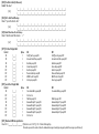
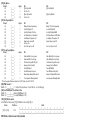
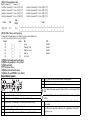
PK5500 v1.1 Installation Instructions
1
2
3
4
5
6
7
8
9
*
0
#
WARNING: Please refer to the System Installation Manual for information on limitations regarding product use
and function and information on the limitations as to liability of the manufacturer.
NOTE: These instructions shall be used in conjunction with the system Installation Manual of the Control Panel
with which this equipment is intended to be used.
2 9 0 0 7 4 9 6 R0 0 1
The PK5500 keypad can be used on security systems with up to 64
zones. These keypads are compatible with the latest version of the
folllowing DSC security systems:
•PC580
•PC585
•PC1555MX •PC1565
•PC1616
•PC1832
•PC1864
•PC5005
•PC5008
•PC5010
•PC5015
•PC5016
•PC5020
3
Specifications
• Temperature range: -10°C to +55°C (14°F to 131°F)
• Humidity (MAX): 93%R.H.
• Plastic enclosure protection degree: IP30, IK04
• Voltage rating: 12VDC nominal
• Connects to control panel via 4-wire Keybus
• 1 keypad zone input/PGM output*
• PK5500 Current Draw: 50mA (standby)/125mA (maximum)
• Wall mount tamper
• 5 programmable function keys
• Ready (Green LED), Armed (Red LED), Trouble (Yellow LED), AC(Green LED)
• Low temperature sensor: Alarm 6°C (43°F)/Restore 9°C (48°F)
NOTE: * Zone not to be programmed as Fire type or 24h type.
NOTE: If any tension found between the front keypad assembly
and wiring, please open the keypad reroute the wire and close
again. Repeat these steps until the keypad is closed properly.
1
2
Wiring
Mount and Wire Keypad
Knock Out
Knock Out
Wiring Slot
Knock Out
Unpacking
The Power keypad package includes the following parts:
•One Power keypad
•Keypad inner door labels
•Four mounting screws
•1 tamper switch
•2 end-of-line resistors
•Installation Instructions
Tamper
Hooks
2.
1.
Hooks
Swing
to engage
Mounting
Mount the keypad where it is accessible to designated points of entry
and exit. Once you have selected a dry and secure location, perform
the following steps to mount the keypad.
Disassemble Keypad
1. Insert a flat head screwdriver into the provided slot (first of two).
2. Move screwdriver toward the back plastic and lift as in the following
diagram. This will unhook one side of the front plastic.
3. Repeat step # 1 and 2 on the second provided slot to disconnect
the front plastic and allow access for wiring.
1. Secure Keypad to wall using mounting holes. Use all 4 screws provided
unless mounting on a single gang box.
2. Place keypad into hooks on the backplate and swing down to engage.
3. Run wire through wiring slot or knockouts. Connect Keybus and PGM/Zone
wiring to keypad. Place tamper switch into tamper hole on backplate.
4. Remove keypad from hooks. Place keypad into backplate, ensure the wire
is pushed back into the wall as much as possible. Route the wire inside
the keypad ensuring high components are avoided. Snap the front assembly closed, ensuring there is no pressure to the keypad from the wire
below.
3.
4.
Tamper
Press to Snap
1. Before wiring the unit, ensure that all power (AC transformer and battery)
is disconnected from the control panel.
2. Connect the four Keybus wires from
PK5500
the control panel (red, black, yellow
RED
and green) to the keypad terminals.
Refer to diagram.
BLK
YEL
3. If programmed as an input, you can
connect a device - such as a door
GRN
contact - to the ‘P/Z’ terminal of the To zone or
keypad. This eliminates the need to PGM output
run wires back to the control panel for
the device. To connect the zone, run one wire from the device to the ‘P/Z’
terminal and the other wire from the device to the B (black) terminal. For
powered devices, run the red wire to the R (positive) terminal and the
black wire to the B (negative) terminal. When using end of line supervision, connect the zone according to one of the configurations outlined in
your system’s Installation Manual.
4. If the ‘P/Z’ terminal is programmed as an output, the output follows the
PGM programmed in Section [080]. A small relay, buzzer or other DC
operated device may be connected between the positive supply voltage
and the ‘P/Z’ terminal (maximum load is 50mA).
Applying Power
Once all wiring is complete, and the equipment is secured to the building
structure with at least two screws apply power to the control panel:
1. Connect the battery leads to the battery.
2. Connect the AC transformer.
For more information on control panel power specifications, see the control
panel Installation Manual.
Programming the Keypad
There are several programming
Toggle Option
options available for the keypad.
These are described below. Pro1_ _ 4 _ _ _ _
gramming the keypad is similar
to programming the rest of the system. When you are in the keypad programming sections, the keypad will display which options are turned on
along the top of the display. To turn an option on or off, press the number
corresponding to the option on the number pad. The numbers of the options
that are currently turned ON will be displayed. For example, if options 1
and 4 are on, the display will look like diagram shown on the different keypad displays.
For information on programming the rest of your security system, please
refer to your system’s Installation Manual.
Broadcasting LCD Labels
All LCD programming is done per keypad. If more than one LCD keypad is
present on the system, labels programmed at one keypad can be broadcast
to all other LCD keypads. Perform the following procedure in order to broadcast labels:
Step 1 - Program one LCD keypad completely.
Step 2 - Make sure all LCD keypads are connected to the Keybus.
Step 3 - Enter keypad programming by pressing [,][8][Installer
Code][,], then enter section [998] at the keypad that was programmed.
The keypad will now broadcast all the information programmed to all the
other LCD keypads on the system.
Step 4 - When the keypad is finished press the [#] key to exit.
NOTE: LCD Label broadcast from this keypad is only compatible
with other PK5500 keypads.
Language Programming
Hold (<>) keys for 2 seconds to enter language programming, scroll to
the desired language and Press [,] to select.
NOTE: If section [077] option 4 is OFF, language programming
can only be performed while in installers programming.
Enrolling the Keypad
The keypad will need to be assigned to a partition and slot if supervision or
keypad zones are being used. Keypad assignments and keypad option programming must be done at each keypad individually.
The 1st digit of keypad assignment is used to determine partition assignment (1 to 8). If partitioning is not used, enter [1]. For Global Keypads,
enter [0].
The 2nd digit of keypad assignment is used to determine slot assignment
for keypad supervision. Each keypad will be assigned a different slot number from 1 to 8. PK5500 LCD keypads come defaulted in slot 8. If LCD keypads are used one LCD keypad must remain in slot 8.
Enter the following at each keypad installed on the system:
1. Enter Installer Programming by pressing [,][8][Installer’s Code]
2. Press [000] for Keypad Programming
3. Press [0] for Partition and Slot Assignment
4. Enter the 1st digit (0 to 8 for partition assignment)
5. Enter the 2nd digit (1 to 8 for slot assignment supervision)
6. Press the [#] key twice to exit programming.
7. After assigning all keypads, perform a supervisory reset by entering
[,][8][Installer’s Code][902] and wait for 60 seconds.
8. Press the [#] key to exit programming after 60 seconds.
Changing Brightness/Contrast
Programming Labels
1. Press [,][6][Master Code].
2. Use the [<][>] keys to scroll to Buzzer Control.
3. There are 21 different levels, use the [<][>] keys to scroll to the
desired level.
4. To exit, press [#].
1. Enter keypad programming by pressing [,][8][Installer Code][,]. Enter
the 3-digit section number for the label to be programmed.
2. Use the arrow keys (<>) to move the underline bar underneath the letter to be changed.
3. Press the number keys [1] to [9] corresponding to the letter you require.
The first time you press the number the first letter will appear. Pressing the
number key again will display the next letter.
1. Press [,][6][Master code].
2. Use the [<][>] keys to scroll to either Brightness Control or Contrast
Control.
3. Press [,] to select the setting you want to adjust.
4. a) ‘Brightness Control’: There are multiple backlighting levels. Use the
[<][>] keys to scroll to the desired level.
b) ‘Contrast Control’: There are 10 different display contrast levels. Use the
[<][>] keys to scroll to the desired contrast level.
5. To exit, press [#].
Changing the Buzzer Level
Emergency Keys
[1] - A, B, C, 1 [4] - J, K, L, 4 [7] - S, T, U, 7 [0] - Space
Press the (
) key for 2 seconds to send a Fire transmission.
Press both (
) keys simultaneously for 2 seconds to send a
Panic transmission.
[2] - D, E, F, 2 [5] - M, N, O, 5 [8] - V, W, X, 8
Broadcasting Door Chime
[3] - G, H, I, 3 [6] - P, Q, R, 6 [9] - Y, Z, 9,0
4. When the required letter or number is displayed use the arrow keys
(<>) to scroll to the next letter.
5. When you are finished programming the Zone Label, press the [,] key,
scroll to “Save,” then press [,].
6. Continue from Step 2 until all Labels are programmed.
ASCII Characters
All door chime programming is done per keypad. If more than one keypad is present on the system, door chime programmed at one keypad can
be broadcast to all other keypads. Perform the following procedure in
order to broadcast door chime:
Step 1 - Program one keypad completely.
Step 2 - Make sure all keypads are connected to the Keybus.
Step 3 - Enter keypad programming by pressing [,][8][Installer
Code][,], then enter section [994] at the keypad that was programmed. The keypad will now broadcast all the door chime information programmed to all the other keypads on the system.
Step 4 - When the keypad is finished press the [#] key to exit.
Limited Warranty
Digital Security Controls warrants that for a period of 12 months
from the date of purchase, the product shall be free of defects in
materials and workmanship under normal use and that in fulfilment of any breach of such warranty, Digital Security Controls
shall, at its option, repair or replace the defective equipment
upon return of the equipment to its repair depot. This warranty
applies only to defects in parts and workmanship and not to
damage incurred in shipping or handling, or damage due to
causes beyond the control of Digital Security Controls such as
lightning, excessive voltage, mechanical shock, water damage,
or damage arising out of abuse, alteration or improper application of the equipment.
The foregoing warranty shall apply only to the original buyer,
and is and shall be in lieu of any and all other warranties,
whether expressed or implied and of all other obligations or liabilities on the part of Digital Security Controls. Digital Security
Controls neither assumes responsibility for, nor authorizes any
other person purporting to act on its behalf to modify or to
change this warranty, nor to assume for it any other warranty or
liability concerning this product.
In no event shall Digital Security Controls be liable for any direct,
indirect or consequential damages, loss of anticipated profits,
loss of time or any other losses incurred by the buyer in connection with the purchase, installation or operation or failure of this
product.
WARNING: Digital Security Controls recommends that the entire
system be completely tested on a regular basis. However,
despite frequent testing, and due to, but not limited to, criminal
tampering or electrical disruption, it is possible for this product to
fail to perform as expected.
Important Information: Changes or modifications not expressly
approved by Digital Security Controls could void the user’s
authority to operate this equipment.
EN50131-1 Grade 2, Class II
Operating Instructions shall be made available to the end user.
© 2008 Digital Security Controls, Toronto, Canada • www.dsc.com
Technical Support: 905-760-3036
Printed in Canada
Keypad Enrollment
Enter keypad programming by pressing [,][8][Installer’s Code][000].
[0] Partition / Slot Assignment
Digit
1st
2nd
Option
Partition Assignment (0=Global Keypad)
Slot Assignment
Valid Range
0 to 8
1 to 8
Default
1
8
I________I
I________I
[1]-[5] Function Key Assignment
[1]
Function Key
Function Key 1 Assignment
[2]
Button
Valid Range
00 to 32
Default
03
Function
Stay Arm
I________I________I
Function Key 2 Assignment
00 to 32
04
Away Arm
I________I________I
[3]
Function Key 3 Assignment
00 to 32
06
Chime On/Off
I________I________I
[4]
Function Key 4 Assignment
00 to 32
14
Sensor Reset
I________I________I
[5]
Function Key 5 Assignment
00 to 32
16
Quick Exit
I________I________I
Keypad Function Keys
Refer to your system installation manual for a complete list of all function key options available for your system.
[00] - Null
[08] - Bypass Mode
[16] - Quick Exit
[01] - Partition 1 Select
[09] - Trouble Display
[17] - Activate Stay/Away
[02] - Partition 2 Select
[10] - Alarm Memory
[18] - *Global Away Arm
[03] - Stay Arm
[11] - User Programming
[19] - Command Output 3
[04] - Away Arm
[12] - User Functions
[21] - Command Output 4
[05] - No Entry Arm
[13] - Command Output 1
[22] - *Global Disarming
[06] - Chime On/Off
[14] - Command Output 2
[23] - Bypass Recall
[07] - System Test
[15] - *Global Stay Arm
[24] - Bypass Group Recall
*Available only on the PC1616/PC1832/PC1864 version 4.2 or higher.
[26] - Time & Date Program
[27] - Partition 3 Select
[28] - Partition 4 Select
[29] - Partition 5 Select
[30] - Partition 6 Select
[31] - Partition 7 Select
[32] - Partition 8 Select
[33] - Local PGM Activate
Keypad Programming
Enter keypad programming by pressing [,][8][Installer Code][,]
[001]-[064] Zone Label 1 to 64
ex. For Zone 1 enter section [001], for Zone 2 enter section [002] etc. Default: “Zone 1” - “Zone 64”
Section
Zone
[001] to [064]
1 to 64
Label
I_____I_____I_____I_____I_____I_____I_____I_____I_____I_____I_____I_____I_____I_____I
I_____I_____I_____I_____I_____I_____I_____I_____I_____I_____I_____I_____I_____I_____I
[065] Fire Alarm Label (28 Characters)
Default:“Fire Zone”
I_____I_____I_____I_____I_____I_____I_____I_____I_____I_____I_____I_____I_____I_____I
[065]
I_____I_____I_____I_____I_____I_____I_____I_____I_____I_____I_____I_____I_____I_____I
[066] Fail to Arm Event Message
Default: “System Has Failed to Arm”
I_____I_____I_____I_____I_____I_____I_____I_____I_____I_____I_____I_____I_____I_____I
[066]
I_____I_____I_____I_____I_____I_____I_____I_____I_____I_____I_____I_____I_____I_____I
[067] Alarm When Armed Event Message
Default: “Alarm Occurred While Armed < >”
I_____I_____I_____I_____I_____I_____I_____I_____I_____I_____I_____I_____I_____I_____I
[067]
I_____I_____I_____I_____I_____I_____I_____I_____I_____I_____I_____I_____I_____I_____I
[071] First User Display Mask
Default
ON
ON
ON
ON
OFF
OFF
OFF
OFF
I____I
I____I
I____I
I____I
I____I
I____I
I____I
I____I
Option
1
2
3
4
5
6
7
8
ON
Hold [P]anic Key prompt ON
Auto-arm Control/Time prompt ON
Quick Arm prompt ON
Interior Arm prompt ON
Quick Exit prompt ON
Thermostat Control prompt ON
ACK All Trouble Prompt ON
Music Input prompt ON
OFF
Hold [P]anic Key prompt OFF
Auto-arm Control/Time prompt OFF
Quick Arm prompt OFF
Interior Arm prompt OFF
Quick Exit prompt OFF
Thermostat Control prompt OFF
ACK All Trouble Prompt OFF
Music Input prompt OFF
Option
1
2
3
4
5
6
7
8
ON
User-initiated Call-up prompt ON
For Future Use
Walk Test prompt ON
Command Output#1 prompt ON
Command Output#2 prompt ON
Command Output#3 prompt ON
Command Output#4 prompt ON
For Future Use
OFF
User-initiated Call-up prompt OFF
[072] Second User Display Mask
Default
ON
OFF
OFF
ON
ON
OFF
OFF
OFF
I____I
I____I
I____I
I____I
I____I
I____I
I____I
I____I
Walk Test prompt OFF
Command Output#1 prompt OFF
Command Output#2 prompt OFF
Command Output#3 prompt OFF
Command Output#4 prompt OFF
[073] Download LCD Message Duration
Default: 003 I_______I_______I_______I (Valid entries are 000-255), 000=Unlimited Message Disp.
This number represents the number of times the downloaded message is cleared by pressing any key while the message is up after timeout).
[074] Key Options
Default
ON
ON
ON
OFF
I____I
I____I
I____I
I____I
Option
1
2
3
4-8
ON
[F]ire Key Enabled
For Future Use
[P]anic Key Enabled
For Future Use
OFF
[F]ire Key Disabled
[P]anic Key Disabled
[076] First Keypad Options
Default
ON
ON
OFF
ON
OFF
ON
OFF
OFF
Option
ON
I____I
1
Display Code when Programming
I____I
2
Local Clock Display ON
I____I
3
Local Clock Displays 24-hr Time
I____I
4
Auto Alarm Memory Scroll Enabled
I____I
5
Local Display of Temperature ON
I____I
6
Bypass Options prompt ON
I____I
7
For Future Use
I____I
8
Auto-Scroll Open Zones ON
[077] Second Keypad Options
Default
Option
ON
ON
I____I
1
Chime Enabled for Zone Openings
ON
I____I
2
Chime Enabled for Zone Closings
OFF
I____I
3
5th Terminal is Keypad PGM Output
ON
I____I
4
Language Selection Enabled
OFF
I____I
5
Power LED Enabled
ON
I____I
6
Power LED indicates AC present
ON
I____I
7
Alarms always Displayed When Armed
OFF
I____I
8
*Low Temperature Warning Enabled
*The Low Temperature Warning is violated at 6°C (43°F) and restored at 9°C (48°F).
OFF
Display “Xs” when Programming
Local Clock Display OFF
Local Clock Displays AM/PM
Auto Alarm Memory Scroll Disabled
Local Display of Temperature OFF
Bypass Options prompt OFF
Auto-Scroll Open Zones OFF
OFF
Chime Disabled for Zone Openings
Chime Disabled for Zone Closings
5th Terminal is Keypad Zone Input
Language Selection Disabled
Power LED Disabled
Power LED indicates AC absent
Alarms not Displayed When Armed
Low Temperature Warning Disabled
[080] PGM Terminal 1
Default: 01 I_______I_______I 1-14 Follow PGM Output Number, 15 Local PGM Pulse , 16 Local PGM Toggle
[082] Local PGM Output Pulse Activation Time
Default: 00 I_______I_______I Minutes (Valid Range 00-99)
Default: 05 I_______I_______I Seconds (Valid Range 00-99)
[101]-[108] Partition Labels
ex. For Partition 1 enter section [101], for Partition 2 enter section [102] etc.
Section
Partition
[101] to [108]
1 to 8
Label
I_____I_____I_____I_____I_____I_____I_____I_____I_____I_____I_____I_____I_____I_____I
I_____I_____I_____I_____I_____I_____I_____I_____I_____I_____I_____I_____I_____I_____I
NOTE: Partition 1 Label is also used as the System Label.
[120]-[151] Command Output Labels
Default: “Command_O/P_1” - “Command_O/P_4”
For Partition 1 Command O/P 1 to 4 enter [120] to [123]
For Partition 2 Command O/P 1 to 4 enter [124] to [127]
For Partition 3 Command O/P 1 to 4 enter [128] to [131]
For Partition 4 Command O/P 1 to 4 enter [132] to [135]
Section
[120]-[151]
For Partition 5 Command O/P 1 to 4 enter [136] to [139]
For Partition 6 Command O/P 1 to 4 enter [140] to [143]
For Partition 7 Command O/P 1 to 4 enter [144] to [147]
For Partition 8 Command O/P 1 to 4 enter [148] to [151]
Cmd.
Output
Part
1to8
Label
I_____I_____I_____I_____I_____I_____I_____I_____I_____I_____I_____I_____I_____I_____I
1to4
I_____I_____I_____I_____I_____I_____I_____I_____I_____I_____I_____I_____I_____I_____I
[201]-[264] Door Chime Sound Programming
You can program the keypad to make up to four different door chime sounds for individual zones.
ex. For Zone 1 enter section [201], for Zone 2 enter section [202] etc.
Default
Option
ON
ON
I____I
1
6 Beeps
OFF
I____I
2
“Bing-Bing” Sound
OFF
I____I
3
“Ding-Dong” Sound
OFF
I____I
4
Alarm Tone
OFF
I____I
5-8
For Future Use
OFF
Disabled
Disabled
Disabled
Disabled
[994][,] Initiate Global Keypad Chime Broadcast
[995][,] Reset Keypad Options to Factory Default
[996][,] Label Default
[997] View Software Version
[998][,] Initiate Global Label Broadcast
[999][,] Reset Keypad EEPROM to Factory Defaults
Keypad Display Symbols
2
1
8
9
2
1
3
4
5
6
12
7
11
10
8
7
1 Fire – Indicates that there are fire alarms in memory.
2 Memory – Indicates that there are alarms in memory.
3 Ready Light (green) – If the Ready light is on, the system is ready for arming.
4 Armed Light (red) – If the Armed light is on, the system has been armed successfully.
5 System Trouble – Indicates that a system trouble is active.
6 AC – Indicates that AC is present at the main panel.
7 Program – Indicates that the system is in Installer’s Programming, or the keypad is busy.
8 Bypass – Indicates that there are zones automatically or manually bypassed.
9 For Future Use
10 Arm Mode – Indicates the mode the panel is armed in.
Stay – Indicates that the panel is armed in the Stay Mode. It will turn on at the beginning of the Exit
Delay
Away – Indicates that the panel is armed in the Away Mode. It will turn on at the beginning of the
Exit Delay
11 Chime – This icon turns on when Door Chime is enabled on the system and will turn off when Door
Chime is disabled.
– When zones are opened, this icon will turn on, and 7 segment displays 1 and 2 will scroll
12 Open
through the open zones.


![LCD5501Z v2-1 im [all] en fr sp 29006002 r001.book](http://vs1.manualzilla.com/store/data/006343065_1-1a60305af960accbcf147395c4481cc7-150x150.png)