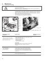
1
838
Spezialnähmaschine
Betriebsanleitung
D
Instruction manual
GB
Postfach 17 03 51, D-33703 Bielefeld • Potsdamer Straße 190, D-33719 Bielefeld
Telefon +49 (0) 521 / 9 25-00 • Telefax +49 (0) 521 / 9 25 24 35 • www.duerkopp-adler.com
Ausgabe / Edition:
10/2008
Änderungsindex
Rev. index: 00.0
Printed in Federal Republic of Germany
Teile-Nr./Part.-No.:
0791 838740
Alle Rechte vorbehalten.
Eigentum der Dürkopp Adler AG und urheberrechtlich geschützt. Jede, auch auszugsweise
Wiederverwendung dieser Inhalte ist ohne vorheriges schriftliches Einverständnis der Dürkopp Adler AG
verboten.
All rights reserved.
Property of Dürkopp Adler AG and copyrighted. Reproduction or publication of the content in any manner,
even in extracts, without prior written permission of Dürkopp Adler AG, is prohibited.
Copyright © Dürkopp Adler AG - 2008
Foreword
This instruction manual is intended to help the user to become familiar
with the machine and take advantage of its application possibilities in
accordance with the recommendations.
The instruction manual contains important information on how to
operate the machine securely, properly and economically. Observation
of the instructions eliminates danger, reduces costs for repair and
down-times, and increases the reliability and life of the machine.
The instruction manual is intended to complement existing national
accident prevention and environment protection regulations.
The instruction manual must always be available at the machine/sewing
unit.
The instruction manual must be read and applied by any person that is
authorized to work on the machine/sewing unit. This means:
–
–
–
Operation, including equipping, troubleshooting during the work
cycle, removing of fabric waste,
Service (maintenance, inspection, repair) and/or
Transport.
The user also has to assure that only authorized personnel work on the
machine.
The user is obliged to check the machine at least once per shift for
apparent damages and to immediatly report any changes (including the
performance in service), which impair the safety.
The user company must ensure that the machine is only operated in
perfect working order.
Never remove or disable any safety devices.
If safety devices need to be removed for equipping, repairing or
maintaining, the safety devices must be remounted directly after
completion of the maintenance and repair work.
Unauthorized modification of the machine rules out liability of the
manufacturer for damage resulting from this.
Observe all safety and danger recommendations on the machine/unit!
The yellow-and-black striped surfaces designate permanend danger
areas, eg danger of squashing, cutting, shearing or collision.
Besides the recommendations in this instruction manual also observe
the general safety and accident prevention regulations!
General safety instructions
The non-observance of the following safety instructions can cause
bodily injuries or damages to the machine.
1. The machine must only be commissioned in full knowledge of the
instruction book and operated by persons with appropriate training.
2. Before putting into service also read the safety rules and
instructions of the motor supplier.
3. The machine must be used only for the purpose intended. Use of
the machine without the safety devices is not permitted. Observe all
the relevant safety regulations.
4. When gauge parts are exchanged (e.g. needle, presser foot, needle
plate, feed dog and bobbin) when threading, when the workplace is
left, and during service work, the machine must be disconnected
from the mains by switching off the master switch or disconnecting
the mains plug.
5. Daily servicing work must be carried out only by appropriately
trained persons.
6. Repairs, conversion and special maintenance work must only be
carried out by technicians or persons with appropriate training.
7. For service or repair work on pneumatic systems, disconnect the
machine from the compressed air supply system (max. 7-10 bar).
Before disconnecting, reduce the pressure of the maintenance unit.
Exceptions to this are only adjustments and functions checks made
by appropriately trained technicians.
8. Work on the electrical equipment must be carried out only by
electricians or appropriately trained persons.
9. Work on parts and systems under electric current is not permitted,
except as specified in regulations DIN VDE 0105.
10. Conversion or changes to the machine must be authorized by us
and made only in adherence to all safety regulations.
11. For repairs, only replacement parts approved by us must be used.
12. Commissioning of the sewing head is prohibited until such time as
the entire sewing unit is found to comply with EC directives.
13. The line cord should be equipped with a country-specific mains
plug. This work must be carried out by appropriately trained
technicians (see paragraph 8).
It is absolutely necessary to respect the safety
instructions marked by these signs.
Danger of bodily injuries !
Please note also the general safety instructions.
Contents
Page:
Preface and general safety instructions
Part 1: Operating instructions - Class 838
(Edition 10/2008)
1.
Product description . . . . . . . . . . . . . . . . . . . . . . . . . . . . . . . . . . . . . . . . . . . .
5
2.
Designated use . . . . . . . . . . . . . . . . . . . . . . . . . . . . . . . . . . . . . . . . . . . . . . .
5
3.
3.1
3.2
Subclasses and sewing equipment
Subclasses . . . . . . . . . . . . . . . . . . . . . . . . . . . . . . . . . . . . . . . . . . . . . . . . . .
Sewing equipment . . . . . . . . . . . . . . . . . . . . . . . . . . . . . . . . . . . . . . . . . . . . .
6
6
4.
Optional equipment . . . . . . . . . . . . . . . . . . . . . . . . . . . . . . . . . . . . . . . . . . . .
7
5.
5.1
5.2
Technical data
Class-specific technical data . . . . . . . . . . . . . . . . . . . . . . . . . . . . . . . . . . . . . . .
Subclass-specific technical data . . . . . . . . . . . . . . . . . . . . . . . . . . . . . . . . . . . . .
8
8
6.
6.1
6.2
6.3
6.4
6.4.1
6.4.2
6.5
6.5.1
Operations
Threading the needle thread . . . . . . . . . . . . .
Winding on the hook thread . . . . . . . . . . . . . .
Changing the hook thread bobbin . . . . . . . . . .
Adjusting the thread tension . . . . . . . . . . . . .
Adjusting the hook thread tension . . . . . . . . . .
Adjusting the needle thread tension . . . . . . . . .
Switching the thread tensioners on/off . . . . . . .
The functioning of the main thread tension and the
in relation to the sewing foot lift . . . . . . . . . . . .
6.6
Adjusting the thread regulator . . . . . . . . . . . .
6.7
Changing the needle for single-needle machines .
6.8
Changing the needle for double-needle machines
6.9
Lifting and folding the top roller . . . . . . . . . . . .
6.10
Sewing foot pressure . . . . . . . . . . . . . . . . . .
6.11
Sewing in reverse (back-tacking) . . . . . . . . . .
6.12
Adjusting the stitch length . . . . . . . . . . . . . . .
6.13
Engaging the safety clutch for hook blockages . . .
6.14
Operating the machine with the positioning drive .
6.14.1 With the pedal . . . . . . . . . . . . . . . . . . . . . .
6.14.2 With the buttons (key panel) . . . . . . . . . . . . .
GB
. . . . . . . . . . . . . .
. . . . . . . . . . . . . .
. . . . . . . . . . . . . .
. . . . . . . . . . . . . .
. . . . . . . . . . . . . .
. . . . . . . . . . . . . .
. . . . . . . . . . . . . .
supplementary thread
. . . . . . . . . . . . . .
. . . . . . . . . . . . . .
. . . . . . . . . . . . . .
. . . . . . . . . . . . . .
. . . . . . . . . . . . . .
. . . . . . . . . . . . . .
. . . . . . . . . . . . . .
. . . . . . . . . . . . . .
. . . . . . . . . . . . . .
. . . . . . . . . . . . . .
. . . . . . . . . . . . . .
. . . . . . . . . . . . . .
. . . . .
. . . . .
. . . . .
. . . . .
. . . . .
. . . . .
. . . . .
tension
. . . . .
. . . . .
. . . . .
. . . . .
. . . . .
. . . . .
. . . . .
. . . . .
. . . . .
. . . . .
. . . . .
. . . . .
.
.
.
.
.
.
.
.
.
.
.
.
.
.
.
.
.
.
.
.
.
.
.
.
.
.
.
.
.
.
.
.
.
.
.
.
.
.
.
.
.
.
.
.
.
.
.
.
.
9
10
10
11
11
12
13
.
.
.
.
.
.
.
.
.
.
.
.
.
.
.
.
.
.
.
.
.
.
.
.
.
.
.
.
.
.
.
.
.
.
.
.
.
.
.
.
.
.
.
.
.
.
.
.
.
.
.
.
.
.
.
.
.
.
.
.
.
.
.
.
.
.
.
.
.
.
.
.
.
.
.
.
.
.
.
.
.
.
.
.
14
14
15
16
17
18
19
20
21
23
23
24
7.
Positioning drive on the Efka DC 1550/DA321G . . . . . . . . . . . . . . . . . . . . . . . . . .
25
8.
8.1
8.2
Sewing on a machine with positioning drive
Automatic machine functions . . . . . . . . . . . . . . . . . . . . . . . . . . . . . . . . . . . . . . .
Example - operating the machine while sewing . . . . . . . . . . . . . . . . . . . . . . . . . . . .
26
27
Contents
9.
9.1
9.2
Maintenance
Cleaning and testing . . . . . . . . . . . . . . . . . . . . . . . . . . . . . . . . . . . . . . . . . . . .
Lubrication . . . . . . . . . . . . . . . . . . . . . . . . . . . . . . . . . . . . . . . . . . . . . . . . . .
Page:
28
30
1.
Product description
The Dürkopp Adler 838 is a special all-purpose sewing machine.
·
·
·
·
·
·
·
·
·
·
2.
It is a post-bed double-lockstitch machine.
It has a bottom drop (feed) mechanism and a drive-powered top
roller.
There are two setting wheels (knobs) which allow the selection of
two stitch lengths. There is also a pneumatically-controlled device
with a button for toggling between the two stitch lengths during
sewing.
Depending on if the subclass is a single-needle or double-needle
sewing machine, the following automatic functions are featured: an
electro-magnetic thread trimmer, pneumatically-controlled
bartacking, a sewing foot lift, and a switchable upper thread
tensioner.
The machine is equipped with a large double-sectioned vertical
hook.
The maximum lift for the sewing foot is 12 mm.
There is a safety clutch to avoid displacing or damaging the hook if
the thread gets jammed in the shuttle track.
Depending on the width of the needle, swappable throat plate
inserts with corresponding stitching holes can be swapped out at
the throat plate.
The machine features automatic wick lubrication and a viewing
window in the arm for watching the machine and hook lubrication.
Some of the oil is lost during the hook lubrication. The remaining oil
is redirected by the pump back to the central reservoir.
Integrated bobbin winder.
Designated use
The 838 machines are suitable for use in producing shoes, decorative
ornamental work, and upholstery. The typical sewing material is leather
(either natural or synthetic). The sewing machine can also be used for
sewing shoe textiles.
The setup of the machine depends on the material to be sewed and
whether it is heavy or extra heavy.
Generally only dry material may be sewn with this sewing unit. The
material may be no thicker than 7 mm when compressed by the
lowered top roller.
The sewing material must not contain any hard objects since the
sewing machine is not equipped with any form of eye protection.
This sewing machine may be set up and operated only in dry,
well-maintained premises. If the sewing machine is used in other
premises which are not dry and well-maintained it may be necessary to
take further precautions which should be agreed in advance (see
EN 60204-31: 1999).
As manufacturers of industrial sewing machines, we proceed on the
assumption that personnel who work on our products will have
received training at least sufficient to acquaint them with all normal
operations and with any hazards which these may involve.
5
GB
Subclasses and sewing equipment
Subclasses
0838 170522
X
Trimming and
seam tacking
large two-section
with thread trimming,
autom. seam tacking
Hook
X
X
X
X
X
X
X
X
838-E3/1,6
838-E4/2,0
838-E5/2,4
838-E6/3,2
Standard
max. stitch length
Max.
Standard *
Top roller diameter
Gearing gap
for the feed dog
Seam clearance gap
Noise intensity level
of machine **
Sewing
speed
Label number
of
polyester thread
-
-
mm
1/min
1/min
mm
mm
mm
dB
(A)
Standard
Range
Needle width:
Nm
Sewing type
Number of neeles
Class and sub-class
0,01
mm
0838 170522
838-E2
0,01
mm
1
heavy
120-160
120
25-10
20
8
2000
1600
35
1,5
-
1
extra
heavy
180-230
180
10-8
10
8
1600
1600
35
1,5
-
0838 270522
Sewing equipment
Sewing equipment
838-E1
*
Machinecontrol
up to 8 mm
X
0838 270522
3.2
Stitch length
autom. foot lift
pneumatic
seam tacking
Number of
needles
one needle, hook to
right of needle
Class and
Subclass
Range
3.1
two needles
3.
2
heavy
120-180
180
25-10
10
8
2000
1600
35
1,5
1,6
2
heavy
120-180
180
25-10
10
8
2000
1600
35
1,5
2,0
2
heavy
120-180
180
25-10
10
8
2000
1600
35
1,5
2,4
2
heavy
120-180
180
25-10
10
8
2000
1600
35
1,5
3,2
You must reduce the sewing speed significantly when sewing through very thick materials.
** Noise level of the special sewing machine at the work place, as measured for the maximum stitch length and
the maximum sewing speed in compliance with DIN 45635-48-A-1-KL2.
6
4.
Optional equipment
Order No.
Optional equipment
0888 220334
Top roller Æ 25 mm, knurled
0888 220344
Top roller Æ 25 mm, smooth
0888 220354
Top roller Æ 25 mm, rubber coating
0888 220364
Top roller Æ 35 mm, knurled (thoroughly)
0888 220374
Top roller Æ 35 mm, smooth
0888 220384
Top roller Æ 35 mm, rubber coating
0888 220394
Top roller Æ 45 mm, width: 3.8 mm
0888 220404
Top roller Æ 45 mm, width: 2.0 mm
9880 888100
Sewing lamp LED
MG55-3 400324
Stand set for machines powered by drive belts
(contains frame, pedal, drawer and table top 1060 x 50 mm)
0700 088804
Table top for drive belt
N800 080030
Edge-guide, swivelling
N800 080004
Edge-guide with roller, swivelling
9780 000108
Compressed air unit
0797 003031
Complete compressed air hose
9805 791113
USB memory key for transferring data with the Efka DA321G control unit
0867 490010
Holder bracket for the Efka V810 or V820 control panel
0688 130384
Knee level for mechanical foot lift
9880 002001
Knee switch
GB
7
5.
5.1
Technical data
Class-specific technical data
Type of stitch
Lockstitch 301
Needle system
134LR, 134 KKLR, 134, 134 D
Foot lift with hand lever
6 mm
Foot lift with knee lever or automatic
12 mm
Remaining thread length after thread trimming
max. 15 mm
Clearance height of machine head
300 mm
Clearance width of machine head
280 mm
Dimensions of footprint of the machine bed plate
178 x 518 mm
Dimensions of footprint of table plate
1060 x 500 mm
Min. height of the table plate
740 mm
Max. height of the table plate
900 mm
Height of machine
max. 1630 mm
Max. (short-term) power consumption
0.8 kW
Compressed air feed
6 bar
Weight of
Efka DC1550 motor
Weight of frame
mm
mm
mm
kg
kg
kg
0838 170522
1
170
52
59
55
30
10
0838 270522
2
170
52
59
56
30
10
More detail about the technical data are given in the chapter 3.2.
8
Weight of
machine head
Column width
perpendicular to
sewing direction
Column length
Class and
subclass
Column heigth in
sewing direction
Subclass-specific technical data
Number of needles
5.2
6.
6.1
Operations
Threading the needle thread
A
B
C
D
4
1
2
3
5
2
3
2
3
GB
Caution: danger of injury!
Turn off the main switch.
The needle must be threaded only when the machine is turned off.
–
–
–
–
–
Follow illustration A when threading single-needle sewing
machines. If the sewing machine is outfitted for the sewing of
heavy-duty materials, then wind the thread around the pin (1).
Follow the illustration B (right side) when threading double-needle
sewing machines. Insert the thread (2) for the left needle into the
left thread tension device and then in the upper eyelet of the thread
lever (4).
When needles are situated side-by-side, thread the needle eye
according to illustration B.
When the needles are situated diagonally to each other, thread the
needle according to the illustration C (right needle) and
illustration D (left needle).
If the sewing machine is intended for the sewing of heavy-duty
materials, then wind the thread around the pin (5).
9
6.2
Winding on the hook thread
2
–
–
–
–
–
–
6.3
1
3
4
Insert the thread as shown in the illustration.
Stick the thread behind the knife blade (1). Then cut by pulling in
the direction of arrow (2).
Put the bobbin on the bobbin shaft and move the bobbin lever (3) in
direction (4).
Start up the machine.
After the thread is wound around the bobbin, stick the thread once
again behind the knife blade (1) and cut off.
Put an empty bobbin on the bobbin shaft for the next winding
process and move the bobbin lever.
Changing the hook thread bobbin
2
10
3
6
1
4
5
Caution: danger of injury!
Be sure to turn off the main switch and wait until the motor has
completely stopped.
–
–
–
–
–
10
Raise up the flap cover (1).
Insert the bobbin (2) with the thread end (3) positioned as shown in
the illustration.
Pull the thread through slit (4) and slit (5). Then close the flap and
secure the thread under the spring (6).
Trim off the thread end as show in the illustration.
The threading and bobbin insertion for the hook to the left of the
needle should be carried out similarly.
6.4
Adjusting the thread tension
6.4.1
Adjusting the hook thread tension
3
1
2
Caution: danger of injury!
Turn off the main switch.
Adjust the shuttle thread tension only when the sewing machine is
turned off.
–
–
Adjust the shuttle thread tension by turning the screw (1) with a
screwdriver. The screwdriver should be inserted through the
opening (2). The tension is increased by tightening the screw.
The thread tension should then be checked with a thread tension
gauge (dynamometer). Insert the thread as shown in the illustration
and pull in the direction of arrow (3).
The thread tension set at the factory depends on the selected
machine configuration (see table below). This tension setting is
suitable for typical sewing processes. You should lower the tension
when working with materials which are soft and thin. If the seam
must be tightly sewn, then you should increase the tension while
simultaneously lowering the sewing speed.
Average values for hook thread tension
Type of sewing
Width of needle used
Nm
Thread tension in
grams
heavy
120-160
90
extra heavy
180-230
90
11
GB
6.4.2
Adjusting the needle thread tension
1
2
3
4
Adjusting the pre-tensioner (1)
– When the main thread tensioner (3) and the supplementary
tensioner (2) are open, there must still be a slight tension
remaining on the needle thread. This residual tension is created by
the pre-tensioner (1). The pre-tensioner (1) influences both the
length of the cut needle thread and the starter thread for the next
seam. (The pre-tensioner (1) is not deactivated with the sewing
foot lift.)
Adjusting the thread tension (2) and (3)
– You can switch off the supplementary tensioner (2) by pressing the
button (4). You can switch the supplementary tensioner (2) back on
by pressing the button (4) again. The switchable supplementary
tensioner (2) is helpful for quickly altering the needle thread
tension. For example, it can be used to attain a good stitch draw
and consistent stitch pattern when working with different textile
materials within a single seam.
– Press the button (4).
– Make a seam on a few layers of materials and regulate the thread
tension by means of the main tensioner (3) until the proper
cross-over point is attained (see illustration).
– Extend the material layers and press button (4) to activate the
supplementary tensioner (2). Control until the proper cross-over
point (thread binding) has been attained.
12
Correct thread interlacing in the center
of the sewing material
Needle thread tension too weak
or
Hook thread tension too strong.
Needle thread tension too strong
or
Hook thread tension too weak.
6.5
Activating and deactivating the thread tension
GB
1
2
3
4
–
The pre-tensioner (1) should never be deactivated.
–
The main tensioner (3) and supplementary tensioner (2) are
switched off using an electro-pneumatic cylinder.
Deactivation can result from:
·
·
·
Pressing the button (4) (see chapter 6.4.2).
Trimming cycle: during the cutting process, the main tensioner (3)
and the supplementary tensioner (2) are temporarily turned off.
The sewing foot lift (see chapter 6.5.1).
13
6.5.1
The influence of the sewing foot lift on the main thread tensioner and supplementary thread
tensioner
Button 4 (see chapter 6.5) on the machine’s key pad can be used to
activate or deactivate the supplementary thread tension at any time.
The parameter F-147 must be set to “1" for this to work.
Sewing foot
Parameter
setting
F-196=0
F-196=1
F-196=2
F-196=3
Sewing foot lift
in the seam
Thread
Thread
main
supplementary
tension
setting
0
0
1
1
0
0
1
1
After thelift
thread has been cut
Thread
Thread
main
supplementary
tension
setting
0
0
0
0
1
1
1
1
1 = Thread tension opened mechanically
0 = Thread tension closed mechanically
·
·
6.6
If the supplementary thread tensioner is open, the state of the
sewing foot lift does not change.
If the machine is turned off, the supplementary thread tension
remains at its previously set state.
Adjusting the thread regulator
2
1
1234
The thread regulator (2) is used to control the quantity of needle thread
required by the stitch formation.
The best sewing results can only be ensured when using a precisely
adjusted thread regulator.
– Loosen the screw (1). Move the thread regulator (2). Then tighten
the screw (1).
– For most sewing jobs, the thread regulator is best positioned when
the right edge of the regulator is aligned with the number 3.
– The setting at position 4 is appropriate when using a thin sewing
material with a very short stitch.
14
6.7
Changing the needle for a single-needle machine
1
2
MAX.
3°
3
4
5
Caution: danger of injury!
Turn the main switch off.
Change the needle only when the sewing machine is switched off.
–
–
–
GB
Move the lever (1) forward in order to loosen the screw which is
used to fasten the needle.
Pull the needle under and out from the needle bar. Insert a new
needle with the needle scarf (2) positioned on the right, according
to section cuts (3) or (4). Push in until the needle has reached the
end stop located in the needle bar hole. The needle should not be
positioned as shown in section cut (5).
Then tighten the needle attachment screw and turn the lever
back (1) to the rear.
CAUTION Danger of breakage!
A bad positioned needle can cause damage to the hook tip.
When changing to a needle with a different thickness, the clearance
between the hook and the needle, as well as the position of the stitch
plate in relation to the post bed, must both be adjusted accordingly
(check the service instructions).
15
6.8
Changing the needle for double-needle machines
1
2
3
4
5
MAX.
3°
Caution: danger of injury!
Only change the needle when the main tensioner is turned off and the
motor has come to a stop.
–
–
–
Loosen screws (1).
Pull the needles under and out from the needle bar. Insert the new
needles with the needle scarf (2) according to section cuts (3)
or (4). Push in until the needles have reached the end stop located
in the needle bar holes. The needles should not be positioned as
shown in section cut (5).
Tighten the needle attachment screws.
CAUTION Danger of breakage!
Poorly positioned needles can cause damage to the hook tips.
When changing to needles with a different thickness, the clearance
between the hook and the needle, as well as the position of the stitch
plate in relation to the post bed, must both be adjusted accordingly
(check the service instructions).
16
6.9
Swiveling and lifting the top roller
1
3
4
Using the hand lever to lift the top roller
– Lift the top roller by turning the lever (1) in the direction of the
arrow until the end stop. The top roller is secured in the upper
position by the lever.
– In order to lower the top roller, turn the lever (1) back to the starting
position.
Or:
– Lift the top roller pneumatically or with the knee lever (3). The lever
then moves back to its starting position.
– The machine can be kept on after the hand lever is used to raise
the top roller (for example, when winding the lower looper thread).
Using the knee lever to lift the sewing foot
Press the knee lever (3) to raise the sewing foot. Release the knee
lever to lower the sewing foot.
Caution!
The machine should not be running when the sewing foot is raised
more than 6 mm over the stitch plate. On a running machine, the
needle bar with the needle holder could collide with the sewing foot or
in the press pad with the double-needle machines.
Automatic and pedal lifting of the sewing foot
– For sewing machines equipped with position drives, the sewing
foot lifting process can be triggered by pressing the pedal (4) down
backwards to position -1. The sewing foot is raised to its top dead
centre point using either the integrated electro-magnet or the
pneumatic cylinder. The sewing foot is lowered after the pedal is
released.
– The machine can be set so that the sewing foot is automatically
raised after each machine stop and no backwards pedal press is
required. In this case, after pressing the pedal the sewing foot is
lowered to position +1. After the seam is completed, the sewing
foot remains permanently raised (see chapter 8). This setting is
described in chapters 6, 7, 8, and 9.
17
GB
Swiveling the top roller
– Turn the hand lever (1) downwards. The top roller is then secured
in the upper position.
– Swivel the top roller to the side by pressing in the direction of
arrow.
Caution: danger of injury!
Only swivel the top roller after first turning off the main switch and
waiting for the motor to stop.
6.10 Sewing foot pressure
1
–
–
–
–
18
+
The top roller pressure is adjusted with the setting wheel (1).
Increasing the top roller pressure = Turn the setting wheel (1)
clockwise.
Decrease the top roller pressure = Turn the setting wheel (1)
counterclockwise.
The pressing force of the top roller should be set just high enough
so that the sewing material is not lifted when the needle pulls out.
You should also verify that the pressure does not prevent the
material from moving properly.
For machines equipped with electric magnets, the maximum
pressing force for the top roller is 100 N. For pneumatic-cylinder
machines, the maximum force is 160 N.
6.11 Sewing in reverse (bartacking)
1
2
3
Using the hand lever to sew backwards
– Press the stitch regulator lever (1) downwards.
The machine will sew backwards as long as the stitch regulator
lever (1) is pressed down.
GB
Using the button to sew backwards
– Press button (2) or move lever (3).
The machine will sew backwards as long as the button (2) or the
lever (3) remains depressed.
Automatic seam bartacking
– For machines equipped with positioning drives, the number of tack
stitches at the seam start and seam end can be programmed.
At seam start (after a previous thread cut), the machine
automatically sews the selected start bartack. At seam end and
pedal position -2, the selected final bartack is sewn and then
thread cutting is begun.
Tack programming is described in chapters 7, 8, and 9.
19
6.12 Adjusting the stitch length
3
2
4
1
The special sewing machine 838 is equipped with two setting wheels.
This allows you to sew with two different stitch lengths which can be
activated during the sewing process by pressing a button.
The stitch lengths are set using the two setting wheels (1) and (4)
found on the machine arm.
– Set the larger stitch length with the upper setting wheel (1). Turn
the setting wheel until the desired number (the stitch length in mm)
is marked (3).
– Set the smaller stitch length with the lower setting wheel (4). Turn
the setting wheel until the desired number (the stitch length in mm)
is marked (3).
– Stitch lengths are equal for both forward and reverse sewing.
CAUTION Danger of breakage!
Make sure that the stitch length set with the lower setting wheel (4) is
not larger as the stitch length set by the upper setting wheel (1).
Note: In order to facilitate the process of adjusting the stitch lengths,
the button (4) should be used to fix the stitch lengths so that they do
not shift.
20
6.13 Engaging the safety clutch for hook blockages
2
1
When the thread gets jammed in the hook track, the safety clutch
disengages.
Caution: danger of injury!
Turn off the main switch.
The safety clutch should only be engaged when the machine is turned
off.
–
–
–
–
Turn the handwheel until the safety clutch engages.
Turn the handwheel in the opposite direction until the hook is free.
If the safety clutch is still disengaged, insert a screwdriver (1) in
the opening (2). Then turn the handwheel until the safety clutch
engages.
Free up the blocked hook by removing the cause of disturbance.
21
GB
For your notes:
22
6.14 Operating the machine with the positioning drive
6.14.1 With the pedal
-2
-1
0
1
2
13
The pedal position is detected by a button with 16 different levels.
Their meanings are listed in the table below:
Pedal position
Pedal movement
Meaning
-2
Fully backwards
Command for cutting the thread (end of seam)
-1
Half backwards
Command for raising the sewing foot
0
Neutral rest position
1
Slightly forwards
2
More forwards
Sew with minimal speed (first level)
3
More forwards
Sew with more speed (second level)
:
:
13
Entirely forwards
Refer to comment below
GB
Command for lowering the sewing foot
:
Sew with maximal speed (twelfth level)
Comment:
The following functions can be programmed to correspond with the rest
position:
– needle position (down/up) and sewing foot position (down/up)
when stop in seam.
– sewing foot position (up/down) after end of seam. (Pedal fully
backwards, then in rest position)
23
6.14.2 With the buttons
6
Button
7
9 8
10
1
2
3
4
5
Function
1
Sew backwards manually
The machine sews backwards for as long as the button is held down.
2
Position the needle in the upper or lower position.
The function of the button can be set with the parameter F-242 (DA321):
1 = needle high/low
2 = needle high
3 = one stitch
(The factory default for delivered machine is 1.)
3
Invoke or suppress the start/final bartacks
In general, if the start and final bartacks are activated, then the next bartack is deactivated
by pressing the button.
If the start and final bartacks are deactivated, then the next bartack is activated by pressing
the button.
4
Switching the stitch length
The function of the button can be defined with parameter F-250 (DA321):
1 = pressing the button switches the stitch length between two pre-set values.
4 = pressing the button changes the stitch length to a lower value. A stitch is then sewn and
the machine reverts back to the original (larger) stitch length.
5
Activating and deactivating the supplementary thread tension (see chapter 6.5)
The button background is illuminated when the supplementary tension is activated.
(The tension discs are closed.)
By pressing the button the supplementary tension is deactivated and the button is not
background lit (the tension discs are opened).
LED
7 and 8
9
Example for
adjusting a button
(for example, 10):
Function
Display empty bobbin for residual thread monitor (left/right bobbin)
LED display “Power On”
By adjusting the screw 10 (located under button 1), you can assign the function
of button 1 to the lever (6).
- Select the function (for example, 1 = sew backwards manually)
- Turn screw 10 (located under button 1) clockwise 90° (the slot is then positioned vertically).
The function can now be invoked by both button 1 and the lever (6).
Caution!
Be sure to deactivate the existing function before changing
the function of lever 6.
24
7.
The Efka DC1550/DA321G positioning drive
GB
The DA321G control unit contains all required operational interfaces
for switching functions and setting parameters. It is possible to operate
without an operating panel, but the seam programming can no longer
be carried out.
The V810 and V820 operating panels can also be connected to the
control unit. They are deliverable as accessories. Seam programming
can be performed with the V820 operating panel.
The “Efka DC1550 - DA321G” Operating Manual contains a more
detailed description of the control unit (see also www.efka.net).
25
8.
8.1
Sewing on a machine with positioning drive
Automatic machine functions
The machine functions listed in the table below are dependent on the
following factors which occur during the sewing process:
– Pre-selected setting
– Pedal position (according to the selection of the machine
operation)
– The particular procedure in the seam preparation
Automatic function
Pre-selected setting
Needle positioning
• Needle is down when machine stops in the seam
• Needle is up when machine stops in the seam
Note: After the seam end*, the machine always stops with the needle up.
Tacking
• Normal
• Decorative**
Start bartack
• Simple
• Double
• Stitch count of normal forward tacking
• Stitch count of decorative forward tacking
• Stitch count of normal backwards tacking
• Stitch count of decorative backwards tacking
Final bartack
• Simple
• Double
• Stitch count of normal backwards tacking
• Stitch count of decorative backwards tacking
• Stitch count of normal forward tacking
• Stitch count of decorative forward tacking
Thread trimming
• Turned on
• Turned off
Automatic sewing foot lift
• Lower sewing foot when stopped in seam
• Raise sewing foot when stopped in seam
*
For pedal position -2, the seam is ended. If the thread trimmer is activated, then after end of function:
thread trimmer on.
** The decorative bartack is a special case. This is because, from the beginning to the end of the tacking, the
needle is in the same stitch insertion point as the previous stitch seam. When the sewing direction changes,
the machine stands still for a moment.
26
The pre-selected automatic functions are described in the instructions
included from the drive manufacturer.
For a detailed description of the control unit, please consult the
enclosed current issue of the operating manual of the motor
manufacturer (see also www.efka.net)
Additional automatic functions can be pre-selected by changing the
drive parameters. Each of the functions has its own parameter number.
A parameter value can then be selected for the parameter number.
The parameters concerned are listed in the parameter sheet (in the
accessory pack).
8.2
Example - operating the machine while sewing
Pre-selected setting:
·
·
·
·
·
·
·
Operation
Needle is down when machine stops in the seam
Normal tacking
Start bartack is doubled
Final bartack is doubled
Thread trimming is turned on
Lowered sewing foot when stopped in seam
Raised sewing foot at seam end
GB
Sewing step
The machine is at standstill. The need is up. The sewing foot is raised.
Load the workpiece.
Press pedal to position +1.
The sewing foot goes down
Let up on pedal to position 0.
The sewing foot goes up
Correct the position of the
workpiece.
Press pedal to position +1.
The sewing foot goes down
Press pedal to position +3.
Sewing the normal double tacking (tack rotary speed is defined by
manufacturer) and subsequent sewing at speed level +3.
Let up on pedal to position 0.
Machine stops with needle down.
Press pedal to position -1.
The sewing foot goes up
Turn workpiece in the needle.
Press pedal to position +5.
Sewing foot lowers and you can sew at the speed level as determined by
the pedal.
Press pedal to position -2.
Lower rotary speed. Sewing the normal double tacking.
Trim thread and machine is at rest with the need up.
The sewing foot raises.
Let up on pedal.
The sewing foot remains raised.
Take out the workpiece.
27
9.
9.1
Maintenance
Cleaning and testing
Caution: danger of injury!
Turn the main switch off.
Maintenance work on the sewing machine must only be carried out
when the machine is switched off.
All maintenance work must be carried out before or at the maintenance
intervals defined in the table (check the “operational hours” column).
When working with materials that are thick and fibrous, shorter
maintenance intervals may be required.
A clean machine is a trouble-free machine.
1
2
3
4
5
6
9
7
8
Maintenance work
to perform
Explanation
Machine head
Points to be particularly well cleaned:
- Area below and around the stitch plate, feed
dog (2), and top roller.
- Area around the hook (7)
- Bobbin housing (1)
- Thread trimmer
- Area around the needle
- Remove sewing dust and
residual thread. (for example,
with compressed air)
Operating interval
(hours)
8
CAUTION!
Be sure to hold the compressed air cleaner so
that no sewing dust is blown into the oil
collector.
- Remove sewing dust and
residual thread.
(for, example with
compressed air)
Take off stitch plate, thread trim blade (4) and
hook plunger ring (6). Remove the bobbin
housing (5) from the hook. Clean the inner
area of the hook. Clean the bobbin housing.
In particular, look for residual adhesive on the
surface (1).
20
- Check the hook.
Check the play on the track between bobbin
housing (5) and the hook (7).
500
28
Maintenance work
to perform
Explanation
- Cleaning the oil collector
Clean the oil collector (8) of dirt and
contaminated oil.
(It can be cleaned with a special vacuum
cleaner.)
Clean the fan screen (9).
(It can be cleaned with the compressed air
gun.)
- Cleaning the fan screen
Operating interval
(hours)
20
20
6
4
8
2
10
1
2
3
GB
Maintenance work
to perform
Explanation
Pneumatic system
The water level must not rise as far as filter
insert (1).
- Use pressure to blow out the water from
water separator (2) after loosening the drain
screw (3).
40
The filter insert (1) is used to filter out dirt and
condensation.
- Separate the machine from the compressed
air supply.
- Unscrew drain screw (3).
There must be no pressure on the
machine’s pneumatic system.
- Unscrew the water separator (2).
- Unscrew the filter insert (1).
Wash out the dirty filter bowl and filter
insert with benzine (do not use a cleaning
solvent). Then blow dry.
- Reassemble the service unit.
500
Check the water level in the
pressure regulator.
Clean the filter insert.
Check the system for leaks.
Operating interval
(hours)
500
29
9.2
Lubrication
2
1
3
Caution: danger of injury!
Oil can cause skin eruptions.
Avoid protracted contact with the skin.
In the event of contact, thoroughly wash the affected area.
Caution!
The handling and disposal of mineral oils is subject to legal regulation.
Deliver used oil to an authorized collection point.
Protect your environment.
Take care not to spill oil.
Oil the sewing machine exclusively with the lubricating oil DA-10, or
equivalent oil with the following specifications:
2
– Viscosity at 40°C
10 mm /s
– Flash point
150°C
DA-10 is available from DÜRKOPP ADLER point of sale under the
following part numbers:
250-ml container:
1 litre container:
2 litre container:
5 litre container:
9047
9047
9047
9047
000011
000012
000013
000014
All areas in the machine head that must be lubricated with oil are
supplied from the central reservoir (1).
– If the oil level falls below the “MIN” mark (3), you should re-fill
through the hole (2) until the level reaches the “MAX” mark.
– Be sure to check the oil level daily!
Caution!
Oil should only be re-filled in the central reservoir or shuttle track.
Other places and points should not be individually lubricated.
Otherwise, the oil could get into areas that are not supposed to be
lubricated.
30