1
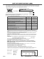
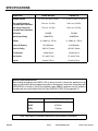
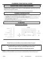
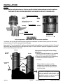
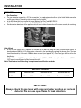
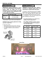
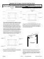
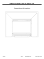
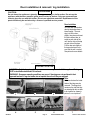
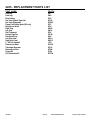
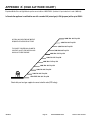
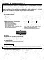
Blaze King
QUALITY HEARTH PRODUCTS
INSTALLATION AND OPERATING INSTRUCTIONS
MODEL 2205 DIRECT VENT INSERT FIREPLACE
Dealer:
Installer:
Phone:
Installation Date:
Serial Number:
INSTALLER: PLEASE LEAVE THIS MANUAL WITH THE CUSTOMER
CUSTOMER: PLEASE KEEP INSTRUCTIONS FOR FUTURE REFERENCE
FOR YOUR SAFETY
DO NOT store or use gasoline or any other
flammable vapors or liquids in the vicinity of this or
any other appliance.
PLEASE READ INSTRUCTIONS CAREFULLY BEFORE
INSTALLING AND OPERATING THE APPLIANCE
WARNING: If the information in these instructions are not
followed exactly a fire or explosion may result causing
property damage, personal injury or loss of life.
IF YOU SMELL GAS:
-
Do not try to light any appliance.
Open windows.
Do not touch electrical switches.
Do not use any phone in your building.
Extinguish any open flame.
Immediately call your gas supplier from a
neighbor's phone. Follow the gas supplier’s
instructions.
- If you cannot reach the gas supplier, call the
fire department.
Installation and service must be performed by a qualified
installer, service agency or the gas supplier.
MANUFACTURED HOME REQUIREMENTS:
This appliance may be installed in an aftermarket
permanently located, manufactured (mobile) home, where
not prohibited by local codes.
This appliance is only for use with the type of gas
indicated on the rating plate. This appliance is not
convertible for use with other gases, unless a certified kit
is used.
MANUFACTURED IN CANADA BY:
MANUFACTURED IN USA BY:
Valley Comfort Systems Inc.
1290 Commercial Way
Penticton, BC
V2A 3H5
Blaze King Industries
146A Street
Walla Walla, WA.
99362
Ph# 1-250-493-7444
OM-2205
CERTIFIED FOR CANADA AND USA
APPROVAL CERTIFICATION BY:
Warnock Hersey part of the:
Intertek Testing Services
Page 1
Ph# 1-509-522-2730
DATE PRINTED: 2/8/05
Revision Date: 04/15/04
CONTENTS
Page
Introduction
3
Copy of certification label
4
Specifications
5
Appliance Description and Dimensions
6
Safety Notice
7
Planning Your Installation
8
Installation Instructions
9 - 14
Flush Mount Assembly Instructions
15 - 16
Door Installation & Removal
17
Log Installation
17
Wiring Diagrams
18
Operating Instructions
19 - 20
Important Information - Mineral Deposits
21
Maintenance
22 -23
Replacement Parts
24
APPENDIX ‘A’ (HIGH ALTITUDE)
25
APPENDIX ‘B’ (CONVERSION KITS)
26
APPENDIX ‘C’ (WARRANTY)
27 - 28
APPENDIX ‘D’ (TROUBLE SHOOTING)
29 –30
Mail your warranty card TODAY, and SAVE
your BILL OF SALE. This card is included with
the accessory package inside each firebox.
In order to receive full warranty coverage and
to expedite service, BKI recommends that you
save your bill of sale and attach it to this page.
By doing this you will have all the necessary
information in the event that your stove may
need service.
OM-2205
Page 2
Your Blaze King Stove has its own
personal serial number, no two
stoves are alike.
The serial
number is located on the stove
label attached to a plate in the slot
below the viewing door..
DATE PRINTED: 2/8/05
Revision Date: 04/15/04
INTRODUCTION
Thank you for purchasing the Blaze King Fireplace and welcome to the Blaze King family of products.It is our goal
to satisfy every Blaze King customer. This owner’s manual explains the steps required to safely assemble, install,
operate, and maintain your new appliance.
The model 2205 is one of the most advanced gas fireplaces on the market. It is designed using the latest
technology and manufactured to the highest quality.
Some of the many features are:
♦ Compact and easy to install.
♦ Adjustible flame control for varying flame aesthetics and heat output.
♦ Gas valve with remote capability, i.e. Optional wall mounted room thermostat or hand held remote control.
♦ Standard heat activated convection fan with variable speed controller.
♦ Standard simulated brick firebox lining.
♦ Certified as a heating appliance with high efficiency. Therefore, the 2205 is suitable for continuous operation
for zone heating.
♦ Realistic three dimensional flowing flames with glowing four piece log set viewed through high temperature
ceramic glass.
♦ Heavy-duty construction for long life and durability.
♦ Comprehensive warranty policy.
LISTING AND CODES
The Blaze King Model 2205 is listed and certified for installation in the U.S.A. and Canada under the following
standards:
- ANSI Z21.88/CGA 2.22-2002,
- CAN/CGA-2.17-M91,
Vented Gas Fireplace Heater.
Gas-Fired Appliances for Use at High Altitudes
Please contact Blaze King, if you have any questions regarding the certification of this appliance.
BUILDING AND FIRE CODES, PERMITS AND INSPECTIONS:
The installation of this gas appliance must comply with your local building and fire codes. Always contact your local
Building Inspector and/or Fire Department before beginning the installation process. If required, obtain a permit
before installation and have the completed installation inspected. Remember that not complying with building and/
or fire codes may jeopardize your homeowner’s insurance. The model 2205 must conform with local codes or, in
absence of local codes, with the National Fuel gas Code, ANSI Z223.1/NFPA 54, or the Natural Gas and Propane
Installation Code, CSA B149.1.
MANUFACTURED HOME REQUIREMENTS:
This appliance may be installed in an aftermarket permanently located, manufactured (mobile) home, where not
prohibited by local codes.
This appliance is only for use with the type of gas indicated on the rating plate. This appliance is not convertible for
use with other gases, unless a certified kit is used.
OM-2205
Page 3
DATE PRINTED: 2/8/05
Revision Date: 04/15/04
COPY OF CERTIFICATION LABEL
Note: A copy of the certification label is provided here for your review. Due to constant up-grades it is possible that
the information shown here may not coincide with the label as attached to the unit. In the event of a discrepancy
between the labels, the label on the unit is considered as the correct one.
Listed Gas-Fired Vented Room Heater
BLAZE KING
Project# 3038397
2205
WH -
Certified for U.S. and Canada
Certifié pour le Canada et les Etas-Unis
Natural Gas
Gaz Naturel
Tested to ANSI Z21.88./CSA 2.33-2002, “Vented Gas Fireplace Heaters” also Tested to Canadian Standards
(CAN/CGA-2.17-M91 “Gas-Fired Appliances For Use At High Altitudes”)
Contrôlée par les normes ANSI Z21.88/CSA 2.33-2002, “Chauffrette à ventilation au gaz naturel ou propane”
aussi contrôlée par les Standards Canadiens (CAN/CGA-2.17-M91)
Direct Vented Gas Fireplace Heater
Propane Gas
Gaz Propane
Input rating (BTU/hr / Kw) 0-610m 0-2000 ft Alt. for United States
Evaluation de la consommation (BTU/hr / Kw) 0-610m 0-2000’ d’altitude.
Orifice (DMS) 0-610 m for United States
NATURAL GAS
Gaz naturel
32,000 / 9.4
32,000 / 9.4
36
LP GAS
Gaz propane
32,000 / 9.4
32,000 / 9.4
53
Input rating (BTU/hr / Kw) 0-1372m 0-4,500 ft Alt. for Canada
Evaluation de la consommation (BTU/hr / Kw) 0-1372m 0-4500’ d’altitude
Orifice (DMS) 0-1372 m for Canada
32,000 / 9.4
32,000 / 9.4
36
32,000 / 9.4
32,000 / 9.4
53
Minimum Input (BTU/hr / Kw)
Consommation minimale (BTU/hr / Kw)
Manifold Pressure (In w.c. / kPa)
Collecteur de pression (In w.c. / kPa)
Manifold Pressure Lo setting (In w.c. / kPa)
Collecteur de pression à bas rendement (In w.c. / kPa)
Minimum Inlet Pressure (In w.c. / kPa)`
Entree de pression minimale (In w.c. / kPa)
17,000 / 4.97
17,000 / 4.97
3.5 / 0.87
17,000 / 4.97
17,000 / 4.97
11.0 / 2.74
1.3 / 0.32
2.7 / 0.67
5.0 / 1.24
12.0 / 3.00
For natural gas when equipped with No. 36 orifice. For propane when equipped with No. 53 orifice.
VENTED GAS FIREPLACE- HEATER NOT FOR USE WITH SOLID FUEL. / NE PAS UTILISER AVEC DES COMBUSTIBLES
SOLIDES
ONLY FOR DIRECT DISCHARGE WITHOUT DUCT CONNECTION / POUR DECHARGE DIRECTE SANS TUYAU DE CONNEXION.
ALSO FOR USE IN MOBILE (MANUFACTURED) HOMES AFTER HOME IS ON SITE.
MAY BE INSTALLED IN A BEDROOM OR SITTING ROOM WHEN INSTALLED WITH A LISTED THERMOSTAT CONTROL IN
CANADA. INSTALL AS PER ANSI Z223.1 IN THE USA.
AU CANADA CET A APPARIEL PEUT ETRE INSTALLE DANS UNE CHAMBRE A COUCHER OU UNE CHAMBRE MEUBLEE S’IL
EST INSTALLE AVEC UNE COMMANDE DE THMOSTAT HOMOLOUEE. AUX ETATS-UNIS L’INSTALLER SELON LA NORME
ANSI Z223.1
MINIMUM CLEARANCES TO COMBUSTIBLES / ESPACES MINIMUM REQUIS ENTRE L’APPAREIL ET DES MATÉRIAUX
COMBUSTIBLES.
Unit to Sidewall / De l’appareil au mur latéral
Top trim to Mantel Height / Hauteur minimale du foyer
25.4 cm (10 in.)
25.4 cm (10 in.) .
40.6cm (16”) Floor protection required (floor protection size diminishes as unit is raised up from the floor).
40.6cm (16”) pouces de protection pour le plancher sont risque.
For more details, see instruction Manual / Pour plus de détails, voir le mode d’emploi
Electrical Rating: 115 Volts, 0.7 Amp, 60 Hz / Consommation électrique: 115 Volts, 0.7 ampère, 60Hz
DANGER: Risk of electrical shock. Disconnect power before servicing unit. Do not route power cord beneath heater.
DANGER: Rique de choc électrique. Débrancher l’appareil avant de le reviser. Ne pas faire passer le fil d’alimentation
électrique dessous la chauffrette.
Part No. 0719B fan or blower assembly may be used.
For installation in masonry fireplaces or any factory built fireplace listed to ULCS 610 in Canada & UL 127 in the United States.
This stove is factory equipped for 0-610m (0-2000 ft) in the United States.
Cette chauffrette est equipe en usine pour une elevation de 0 à 610m ( 0- 2000 pi).
This stove is factory equipped for 0-1372m (0-4500 ft) in Canada.
Cette chauffrette est equipe en usine pour une elevation de 0 à 1372m ( 0– 4500 pi).
This vented gas fireplace is not for use with air filters.
FOR USE WITH GLASS DOORS CERTIFIED WITH THE APPLIANCE ONLY
This appliance is only for use with the type of gas indicated on the rating plate and may be installed in an aftermarket, permanently located, manufactured home
(USA only) or mobile home, where not prohibited by local codes. See owner’s manual for details. This appliance is supplied with a conversion kit.
Manufacture Date: / Date de fabrication:
Manufactured in Canada By:
Fabriqué au Canada par:
Manufactured in U.S.A.
Fabrique au U.S.A. par:
OM-2205
Valley Comfort Systems Inc.
1290 Commercial Way
Penticton, B.C.
V2A 3H5 Canada
Blaze King Industries
146A Street
Walla Walla, WA
99362 U.S.A.
2003
2004
2005
2006
2007
JAN
FEB
MAR
APRIL /
2008
MAY /
JUNE /
JULY /
AUGUST /
2009
SEPT
OCT
NOV
DEC
2010
MAI
Page 4
JUIN
JUIL
DATE PRINTED: 2/8/05
AVRIL
AOÛT
Revision Date: 04/15/04
SPECIFICATIONS
MODEL 2205
Natural Gas (NG)
Propane (LP)
1.3 - 3.5 in. w.c. (0.32 - 0.9 kPa)
2.7 - 11.0 in. w.c. (0.67- 2.75 kPa)
Min. Supply Pressure for
Purpose of Input Adjustment
5.0 in. w.c. (1.2 kPa)
12.0 in. w.c. (3.0 kPa)
Max. Supply Pressure for
Purpose of Input Adjustment
7.0 in. w.c. (1.8 kPa)
14.0 in. w.c. (3.5 kPa)
36# DMS
53# DMS
32,000 BTU/hr
32,000 BTU/hr
0 - 4,500 ft. (0 - 1372 m)
0 - 4,500 ft. (0 - 1372 m)
Primary Air Opening
1/4 in (Minimum).
1/4 in (Minimum).
Electrical Rating
120 V.A.C. System
120 V.A.C. System
Variable Speed
Variable Speed
Vent System
Bi - axial (3” liner)
Bi - axial (3” liner)
Log Set
Ceramic (4 Piece)
Ceramic (4 Piece)
Manifold Pressure
Orifice Size
Nominal Input Rating
Altitude
Circulating fan
HIGH ALTITUDE INSTALLATION
When installing this appliance over 4500 ft (1372 m) above sea level in Canada, the appliance must be
properly de-rated and installed according to local codes, in the absence of local codes in accordance with
CAN/CGA-B149, in Canada. In the US for installations above 2000ft the appliance must be installed in
accordance with the current National Fuel Gas Code, ANSI Z223.1/ NFPA 54 (see appendix ‘A’).
Minimum Fireplace Opening
WIDTH
31 7/8”/810mm
HEIGHT
22”/559mm
DEPTH
17”/432mm
Note: See page 8 for detailed dimension and clearance information.
OM-2205
Page 5
DATE PRINTED: 2/8/05
Revision Date: 04/15/04
APPLIANCE DESCRIPTION & DIMENSIONS
APPLIANCE DIMENSIONS
OM-2205
Page 6
DATE PRINTED: 2/8/05
Revision Date: 04/15/04
SAFETY NOTICE
IF THIS APPLIANCE IS NOT PROPERLY INSTALLED, A HOUSE FIRE, OR EXPLOSION MAY
RESULT. FOR YOUR SAFETY, FOLLOW THE INSTALLATION DIRECTIONS. CONTACT
LOCAL BUILDING OR FIRE OFFICIALS ABOUT RESTRICTIONS AND INSTALLATION
REQUIREMENTS IN YOUR AREA. PLEASE READ THIS ENTIRE MANUAL BEFORE YOU
INSTALL AND USE YOUR NEW APPLIANCE. FAILURE TO FOLLOW INSTRUCTIONS MAY
RESULT IN PROPERTY DAMAGE, BODILY INJURY OR DEATH.
♦
NEVER vent the appliance into other rooms or
buildings. The appliance must be vented
ONLY to the outside.
♦
Fire Extinguisher: Every home should have at
servicing a room heater must be replaced
least one fire extinguisher. An approved Class
prior to operating the appliance.
A-B-C extinguisher should be mounted on the
♦ Installation and repair should be done by a
wall near an exit and close to the appliance,
but not so close that accessibility to the
qualified service person.
extinguisher could be blocked by a fire. Your
♦ The appliance and venting should be
local Fire Department can advise you
inspected before use by a qualified
concerning the most appropriate location.
♦
Smoke Detectors & Carbon Monoxide
Detectors: Install at least one smoke detector
on each floor of your home to ensure your
safety. It should be located away from the gas
appliance and close to the sleeping areas.
Follow the smoke detector manufacturers
placement installation and maintenance
instructions. Your local Fire Department may
provide assistance in selecting smoke
detectors and CO-detectors. It is strongly
recommended, for your family’s protection,
that a CO-detector be placed in all homes that
utilize gas in any form.
Clothing or other flammable materials should
not be placed on or near the appliance.
•
♦
The flexible cord provided connected to a
line voltage electrical supply.
♦
Any safety screen or guard removed for
person and have inspections by a qualified
service person annually.
♦
More frequent cleaning may be required
due to excessive lint from carpeting,
bedding materials, etc.
♦
It is imperative that control compartments,
burners, & circulating air passageways of
the appliance are kept clean.
♦
To clean the stove, make sure the
appliance is off and cold. Then remove
the logs and embers and use a vacuum to
clean burner and air openings in the
bottom and back of the appliance. Replace
the logs and embers.
SAFETY PRECAUTIONS FOR THE INSTALLER
1)
2)
3)
4)
Wear gloves and safety glasses for protection.
Exercise extreme caution when using ladders or when on roof tops.
Be aware of electric wiring locations in walls and ceilings.
Use a back support when doing any heavy lifting.
♦
Do not use this heater if any part has been under water.
Immediately call a qualified service technician to inspect
the heater and to replace any part of the control system
and any gas control which has been under water.
♦
The flow of ventilation air must not be obstructed.
Adequate clearances must be mantained around the
bottom grill to provide for adequate ventilation air.
OM-2205
♦
Due to high temperatures, the appliance should be
located out of traffic and away from furniture and
draperies.
♦
Children and adults should be alerted to the hazards of
high surface temperatures and should stay away to
avoid burns or clothing ignition.
♦
Young children should be carefully supervised when they
are in the same room as the appliance .
Page 7
DATE PRINTED: 2/8/05
Revision Date: 04/15/04
PLANNING YOUR INSTALLATION
MANUFACTURED / MOBILE HOME REQUIREMNTS
This appliance when installed must be electrically grounded in accordance with local codes or, in the absence of local codes
the National Electrical code ANSI/NFPA 70 in the U.S.A or the current CAN/CGA B149 Installation Code and the current
Canadian Electrical code CSA C22.1 in Canada.
♦
Ensure as in any installation, that structural members are not cut or weakened during installation .
PLANNING YOUR INSTALLATION
Please note the following key points regarding the location of your appliance.
♦ This appliance requires a dedicated masonry fireplace or factory built fireplace, built to ULCS 610 in Canada & UL 127 in
the United States, to run the two 3” liners down (see vent installation on page 10 & 11).
♦ A sufficient gas pressure is required to supply the unit with a minimum of 5.0” W.C. for natural gas and 12.0” W.C. for
LPG (see gas installation on page 12 –13).
♦ Allow adequate accessibility clearances for servicing and proper operation.
A suitable power outlet is required to provide power to the fan.
CLEARANCES
MINIMUM FIREPLACE DIMENSIONS
Minimum Clearance to combustibles must be maintained as outlined in this manual
WARNING: Failure to position the parts in accordance with these diagrams or failure to use only parts specifically
approved with this appliance may result in property damage or personal injury.
Be sure to leave adequate accessibility for servicing and proper operation.
CAUTION: This appliance is designed for use in a factory built solid fuel burning fireplace meeting the requirements of ULCS 610
in Canada & UL 127 in the United States. It cannot be enclosed by combustible material and used as a built-in gas fireplace.
OM-2205
Page 8
DATE PRINTED: 2/8/05
Revision Date: 04/15/04
CLEARANCES TO COMBUSTIBLES
OM-2205
Page 9
DATE PRINTED: 2/8/05
Revision Date: 04/15/04
INSTALLATION
VENTING
Please follow the venting instructions as strictly as possible to obtain the best performance from the appliance.
THESE ARE THE ONLY VENTING COMPONENTS APPROVED FOR USE WITH THE MODEL 2205.
Duravent Product Numbers:
High Wind Cap
Adapter
#991
#923GK
Optional Flex Connectors
#2150
(2 required if used)
Security Chimney
Assembly
#3PDVCV
Duravent
Security Chimney
Assembly (Shown with high wind cap)
Assembly (wind cap)
VENT ASSEMBLY
Only use approved 3” double walled flex liner for correct installation
The exhaust and air intake pipe must be securely fastened to the appliance and terminal and all joints must be secured
using a minimum of 3 screws evenly spaced around the pipe.
Approximately 1” from the end of the 3” appliance exhaust pipe outlet at the appliance air intake pipe and at the 3” terminal
connections apply a bead of Mil Pac or other high heat silicone 1/4” wide. Slide the 3” pipe onto the appliance and secure
with 3 screws evenly spaced to the outlet.
Exhaust
3” Double
wall Flex
Air inlet
Mil Pack Sealant
Self Tapping
Screw
Some general venting rules for best venting
performance:
1. Observe local code restrictions, if any, regarding
the installation of this type of gas appliance.
2. Observe the venting chart on the following page.
3. Terminate the vent with a suitable vent
termination.
When installed in accordance with the
manufacturer’s instructions the combustion
air supply will be in the same pressure zone
as the vent outlet.
This direct vent appliance must be installed
using an approved venting system. All
vent pipe joints must be sealed with a high
temperature sealant in order to meet the
ANSI/CSA leakage limit standards.
OM-2205
Page 10
DATE PRINTED: 2/8/05
Revision Date: 04/15/04
INSTALLATION (DIRECT VENT)
This appliance must not be connected to a chimney flue serving a separate solid-fuel burning appliance.
VENTING CHART
The model 2205 is only certified for vertical terminations.
“WARNING: Failure to position the parts in accordance with these diagrams or failure to use only parts
specifically approved with this appliance may result in property damage or personal injury”.
Exhaust
Connector
Intake
Connector
VENT TERMINAL CLEARANCES
30 FT MAXIMUM
VERTICAL RISE,
MINIMUM 8 FT
2FT MAXIMUM
HORIZONTAL RUN
Consult local codes for minimum vent cap height above the roof
(X), vent must be a minimum of 2’ from any wall.
The fireplace flue damper can be fully blocked open or removed
for installation of the gas fireplace insert.
The fireplace and chimney must be clean and in good working
order and constructed of non-combustible materials. Chimney
cleanouts must fit properly.
OM-2205
Page 11
Refractory material, glass doors, screen rails, screen mesh and
log grates can be removed from the fireplace before installing
the gas fireplace insert. Smoke shelves, shields and baffles
may be removed if attached by mechanical fasteners. Trim
panels or surrounds shall not seal ventilation openings in the
fireplace.
DATE PRINTED: 2/8/05
Revision Date: 04/15/04
INSTALLATION (GAS SUPPLY)
ONLY PERSONS LICENSED TO WORK WITH GAS PIPING MAY MAKE THE NECESSARY GAS CONNECTION TO
THIS APPLIANCE. YOU ARE NOW READY TO HOOK UP THE GAS SUPPLY. BE SURE GAS PLUMBING
INSTRUCTIONS AND ALL PROVINCIAL AND LOCAL CODES ARE CAREFULLY FOLLOWED. USE APPROVED
FLEXIBLE GAS CONNECTIONS OR RIGID PIPING, DEPENDING ON PROVINCIAL AND LOCAL CODES, TO
ATTACH BURNER TO GAS SUPPLY. BE SURE TO USE PROPER SIZE GAS SUPPLY LINE. CAREFULLY CHECK
ALL CONNECTIONS WITH A SOAP AND WATER SOLUTION FOR GAS LEAKS. EACH INSTALLATION MUST
CONFORM TO ALL LOCAL, PROVINCIAL AND NATIONAL CODES. REFER TO THE NATIONAL FUEL GAS CODE,
LOCAL ZONING AND CODE AUTHORITIES FOR DETAILS ON INSTALLATION REQUIREMENTS.
EXISTING GAS SUPPLY
Before interrupting the existing gas supply it is recommended that the following be checked.
Shut down all gas appliances and carry out a pressure test to insure there are no existing leaks on the system.
Before connecting the appliance to the gas supply line, double check that the appliance you have purchased is
designed for the gas type you are using. The gas type markings are located on the certification label and also
on the appliance’s gas valve.
♦ Check the gas pressure to insure you will be able to supply the minimum inlet pressure for the appliance (see
page 12).
♦ Check your pipe sizing to insure sufficient volume will be supplied to the appliance.
♦
♦
GAS SUPPLY INSTALLATION
Provide adequate clearance for proper installation and checking of the gas connections.
Have your gas supplier or a qualified gas fitter run a gas supply line into the gas fireplace. The line must be
properly sized and fitted according to the installation codes. Up stream of the appliance supply connection, the
fitter shall provide an easily accessible manual shut-off valve.
The appliance and its individual shut-off valve must be disconnected from the gas supply piping system during any
pressure testing of that system at test pressures in excess of 1/2 psi (3.5 kPa). The appliance must be isolated
from the gas supply piping system by closing its individual manual shut-off valve during any pressure testing of the
gas supply piping system at test pressures equal to or less than 1/2 psi (3.5 kPa). Failure to do so will damage the
appliance’s gas valve. Such damage is not covered by the manufacturer’s warranty.
Check for proper gas supply pressure by loosening the set-screw on inlet pressure tap (marked IN) on the gas
valve with a small flat tip or Phillips screw driver and placing a test gauge on the tap.
The minimum permissible gas supply pressure is 5.0 in. w.c. (1.24 kPa) for natural gas and 12.1 in. w.c. (3.00 kPa)
for propane. Maximum gas supply pressure should never exceed 14.0 in. w.c. (3.48 kPa) or 1/2 psi. for both
natural gas and propane.
BE SURE TO TIGHTEN THE PRESSURE TAP SET-SCREW AFTER CHECKING THE PRESSURE. CHECK
ALL GAS CONNECTIONS FOR GAS LEAKS.
OM-2205
Page 12
DATE PRINTED: 2/8/05
Revision Date: 04/15/04
INSTALLATION
PIPING DETAIL
♦
♦
♦
♦
Gas Connection:
The gas connection supplied is a 1/2” flare connection. The supply pipe can be either rigid or listed flexible connection
and/or copper tubing if allowed by state, provincial and local codes.
In the USA follow local codes and/or the current National Fuel Gas Code, ANSI Z223.1.
In Canada consult local authorities and the CAN/CGA B149 installation codes.
Provide a union downstream of the appliance shut-off valve to allow disconnection of the burner assembly for servicing.
High Altitude:
♦ In the USA the model 2205 is approved for altitudes up to 2000 feet using the factory installed burner orifice. At
elevations above 2000 feet, U.S. codes require a decrease in the input rating by replacing the burner orifice. The input
should be reduced by 4% for each 1000 feet above sea level (see appendix ‘A’). Check local gas utility for orifice size
identification.
♦ In Canada the model 2205 is approved for altitudes up to 4,500 feet (1375 meters). For altitudes above 4,500 feet
(1375 meters) consult the local codes for correct de-rating.
Note: The difference in altitude rating is a requirement of certification standards.
GAS SUPPLY PRESSURE
Natural Gas
Minimum 5.0”w.c
Maximum 10.5”w.c
Recommended 7”w.c
LP GAS
Minimum 12.1”w.c
Maximum 14.0”w.c
Recommended 12.5”w.c
IMPORTANT:
Always check for gas leaks with soap and water solution or gas leak
detector. Do not use open flame for leak detection.
OM-2205
Page 13
DATE PRINTED: 2/8/05
Revision Date: 04/15/04
INSTALLATION
AERATION ADJUSTMENT
OPTIONAL THERMOSTAT
IMPORTANT: Aeration adjustment is critical
to the correct functioning of the appliance.
Carbon build up, flame lift or any
malfunction due to the aeration not being
correctly adjusted during installation is NOT
covered under the warranty
WARNING: The gas valve of this appliance
operates on a millivolt system and is not
intended to be connected to main power.
FACTORY SETTING
Natural Gas
1/4” (6.35 mm) Open
LP GAS
1/4” (6.35 mm) Open
If required, a wall thermostat may be installed.
Blaze King provides a thermostat but any CSA,
ULC or UL approved 250-750 millivolt rated
non-anticipator type thermostat may be used.
It is important to use the correct gauge wire
when installing your thermostat.
See wiring diagrams in on page 16 for
details on valve connections.
Note: Aeration is factory set, but may need adjustment
CAUTION: Parts requiring adjustment during
operation may be hot.
Note: When installing a remote control
or wall switch use the correct gauge of
wire. See table below.
To adjust the air shutter:
• Loosen screw on round access panel & rotate open.
• Use supplied adjusting rod and insert into air shutter.
• Turn adjuster clockwise or counter clockwise as
required.
Open -Short
blue flame
Wire Size
Max. Length
14 GA.
50 FT.
16 GA.
32 FT.
18 GA.
20 FT.
20 GA.
12 FT.
22 GA.
9 FT.
Closed - Tall
yellow flame
Burner Flame
OM-2205
Page 14
DATE PRINTED: 2/8/05
Revision Date: 04/15/04
SHROUD KIT & GRILL ROD KIT INSTALLTION
ONLY USE TRIM KIT (PART# Z2223) SUPPLIED BY THE MANUFACTURER
REMOVE ALL PROTECTIVE COATING FROM GOLD PLATED SURFACE AFTER SHROUD INSTALLATION IS COMPLETE,
BUT PRIOR TO FIRING THE STOVE! UPPER AND LOWER AIR INTAKE OPENING MUST NOT BE COVERED OR BLOCKED
Once all the venting and gas is completed install the shroud.
Step 1
Step 2
After the unit has been installed it is time to install the shroud & grill
rod kits. Remove the viewing glass retainer and glass, use caution
they are not attached to each other. Remove the shroud left side
panel from the shroud and attach the label plate holder with 2
screws and attach the panel to the unit with one screw Be sure to
pull the label plate through the slot in the panel and route the cable
so it’s not catching on anything . Now attach the rheostat to the left
side panel. Place the shroud face down in front of the unit being
careful not to damage the paint and plug the power cord and the on/
off switch into the 2 wires on each side of the unit. Carefully stand
the shroud up and attach to the unit with all remaining screws, it
might be necessary to loosen some of the mounting brackets where
attached to the shroud to allow for some screw hole alignment. Now
reinstall the viewing glass and the glass retainer see page 17.
The next step is to mount the upper and lower grill rod kits. They are
fasten with 2 screw per side to the grill mounting brackets as shown
above. Note that the 3 rod section is installed on the top and the 4
rod section is installed on the bottom. Be sure to center the grill rods
so you don’t run into trouble in step 3.
Top
Step 3
L-Brackets X2
Brass Screws X4
Right
Left
TRIM PACK PART
# H /Z2208
After the grill rod kits have been installed it is time to fasten the grill
mounting covers over the grill mounting brackets. These covers are
secured with 1 screw per side as shown above.
OM-2205
The final step is to install the trim pack around the perimeter of the
shroud kit. Fasten the 3 pieces together with the L-brackets, as
shown above, and slide the now 1 piece trim pack down over the
outside edges of the shroud kit. Remove all protective coating from
the gold plated surfaces. See next page for picture of finished
installation.
Page 15
DATE PRINTED: 2/8/05
Revision Date: 04/15/04
SHROUD KIT & GRILL ROD KIT INSTALLTION
OM-2205
Page 16
DATE PRINTED: 2/8/05
Revision Date: 04/15/04
Door installation & removal / log installation
TO OPEN DOOR
CAUTION:
Do not abuse the appliance’s glass by striking, slamming or similar action. Do not use the
appliance with the door removed, glass panel cracked or broken. Only use approved 5mm
ceramic glass for use with this heater. Do not use substitute materials. Replacement of the
panel should only be carried out by a licensed qualified service person.
Door Installation
To install door slide bottom
door lip into bottom door retainer bracket. The next
step is to lift the door ,
slightly, into place and insert
the door retainer tabs, located on each side of the
unit, into the slots at the top
on each side of the door.
Pull the door out slightly at
the top and release to ensure that the unit is sealed.
See picture for more details.
LOG INSTALLATION
CAUTION: Only the log set supplied by the manufacturer may be used with this appliance. The log set
MUST be installed as described in this manual.
WARNING: Dangerous operating conditions may occur if these logs are not positioned in their
approved locations. If logs are broken, do not operate the unit until they are replaced.
OM-2205
1
2
4
5
3
6
Page 17
DATE PRINTED: 2/8/05
Note:
If the user desires the installation of the twigs may be
reversed. The twigs must
remain on the side that they
are intended for but are able
to be installed as
withshown
as shown
in
in picture
picture
5 or
5 or
asas
in picture
in picture
7. 7.
7
Revision Date: 04/15/04
WIRING DIAGRAMS
THIS MOBILE/MANUFACTURED HOME APPROVED APPLIANCE MUST BE GROUNDED TO THE STEEL CHASSIS OF THE
HOME WITH A 8 GAUGE COPPER WIRE USING A SERRATED OR STAR WASHER TO PENETRATE PAINT OR PROTECTIVE
COATING TO INSURE GROUNDING.
Observe good wiring practice: Label all wires prior to disconnection when servicing controls. Wiring errors can
cause damage to the unit and may cause dangerous operation. Verify proper operation after servicing.
WARNING: Electrical Grounding Instructions
This appliance is equipped with a three-prong (grounding) plug for your protection against shock hazard and should be plugged
directly into a properly grounded three-prong receptacle. Do not cut or remove the grounding prong from this plug.
Blower
Control
120 VOLT CIRCUIT
Blower
Thermostat
Cordset
Ground
Blower
MILLIVOLT CIRCUIT
Room Thermostat
(optional)
Pilot
Assembly
Piezo Push
Button Ignitor
Remote Control (Optional)
On
Off
Bridge across
these terminals
(TP-TH) to test
ancillary switching
TP
TH
TH -TP
TH
Pilot
Tube
Honeywell Valve
Thermocouple
OM-2205
Page 18
DATE PRINTED: 2/8/05
Revision Date: 04/15/04
OPERATING INSTRUCTIONS—PRE-START UP CHECK LIST
FOR YOUR SAFETY READ - BEFORE LIGHTING
WARNING: IF YOU DO NOT FOLLOW THESE INSTRUCTIONS EXACTLY, A FIRE OR EXPLOSION MAY
RESULT CAUSING PROPERTY AND/OR PERSONAL INJURY
DO NOT: Use tools to operate controls, only use your hand to push in and turn the controls.
DO NOT: Try to repair the appliance. Call a qualified service technician.
DO NOT: Use this appliance if any part has been under water. Immediately call a qualified service technician to inspect
the appliance and replace any part of the gas control system which has been under water.
DO NOT: Use this appliance if you smell gas.
WHAT TO DO IF YOU SMELL GAS:
♦
♦
♦
♦
OPEN WINDOWS.
DO NOT TOUCH ANY ELECTRICAL SWITCH; DO NOT USE THE PHONE IN YOUR BUILDING.
EXTINGUISH ANY OPEN FLAME.
IMMEDIATELY CALL YOUR GAS SUPPLIER FROM A NEIGHBOR’S PHONE AND FOLLOW THE GAS SUPPLIER’S INSTRUCTIONS.
FINAL CHECK
START-UP PROCEDURE
INSTALLER: Before leaving the appliance with the customer,
you must check the operation of the appliance:
♦ Thoroughly check the entire appliance for gas leaks.
♦ Check correct rating by clocking the appliance at 15
minutes (see label).
♦ Check flame picture. Adjust primary air if required (see
page 14).
♦ Take time to go through the unit with the customer.
♦
♦
♦
♦
♦
♦
♦
♦
♦
♦
♦
NOTE: When first fired, the unit will produce an odor. This is
normal and is part of the paint curing process. It is
recommended that you open a few windows to ventilate the
room. This will be noticeable for at least 6 hours. During the
first hour smoke detectors in the house may be set off.
Following the initial burn-in period, the glass panel may
require cleaning.
CAUTION: Do not clean the glass when the appliance is
hot!
When the appliance is fired from cold the glass may fog up.
This is due to condensations and is normal.
Make yourself familiar with these instruction before operating
the appliance.
Check any loose electrical wires that may cause a shock.
Check around the appliance for gas leaks. IF YOU SMELL
GAS, follow the instructions on the front cover of this
manual.
Check to see that logs are correctly positioned. The pilot
light should be visible.
Check to make sure that venting is secure.
Check all external parts, such as grills, doors and control
cover are properly attached and fastened.
CAUTION: Do not turn the unit off and on again within a
minimum of a 60 second wait.
OM-2205
1. Set the thermostat, if present, to the lowest level. Switch
burner switch to OFF. Set the flame adjustment knob to the
HI position. Press slightly and turn the control knob
clockwise to the OFF position and wait 5 minutes; thus
allowing any gases to escape which may have accumulated
in the combustion chamber. IF YOU SMELL GAS STOP!
FOLLOW INSTRUCTIONS ON PAGE 19.
(Note: LP gases do not vent upward). Then follow steps 2
and 3 to establish pilot.
2. Press slightly and turn control knob counterclockwise to
PILOT position; depress control knob and light pilot by
repeatedly pressing the sparker. Venting of air may take
place at the pilot prior to the flow of fuel gases. Once flame
is established, hold knob depressed for approximately 60
sec.
3. Release knob. If the pilot will not light or the control knob
does not pop up when released, turn the control knob to
OFF and call your service technician or gas supplier. If the
pilot should go out, turn the control knob to OFF position and
repeat steps 1, 2 and 3.
Note: this will allow reset of INTERLOCK for proper lighting
of pilot.
Also the Honeywell valve is equipped with a safety lockout,
once in the off position you must wait until the thermopile has
cooled down before attempting to light the pilot
(approximately 3 minutes).
4. Press and turn control knob counterclockwise to ON
position.
5. Turn flame and heat adjustment knob to the desired comfort
level from HIGH to LOW.
6. Turn thermostat to the desired comfort level or turn ON/OFF
switch to the ON position.
Page 19
DATE PRINTED: 2/8/05
Revision Date: 04/15/04
OPERATING INSTRUCTIONS
CONVECTION FAN OPERATION
TEMPORARY SHUT-DOWN
To turn off the main burner only, set the thermostat to the
lowest setting or turn switch to OFF. Press and turn the
knob clockwise to PILOT position.
COMPLETE SHUT-DOWN
Press and turn the knob clockwise to the OFF position.
The convection fan speed control is located adjacent
to the gas controls. Turning the control knob all the
way anticlockwise will turn off the convection fan. Adjust the blower speed to the desired speed.
NOTE: The fan will turn on once the unit has reached
operating temperature. This prevents the discharge of cold
air.
♦
NORMAL OPERATING SOUNDS
CONTROL KNOB POSITIONS
Honeywell
Pilot On
♦
FIREBOX: You may hear some cracking or ticking
sounds on start-up and shut-down. This is due to the
expansion and contraction of the steel in the firebox.
♦
BLOWER: We use high efficiency fans in our appliances. You may hear a whirring sound when the fan
turns on. This will decrease or increase depending on
the speed setting of the fan.
♦
PILOT FLAME: You may detect a very slight whisper
sound from the pilot when it is turned on.
♦
These are all normal sounds associated with this
type of appliance and should not be considered as
defects.
Robertshaw
Burner On
Unit Off
OM-2205
Page 20
DATE PRINTED: 2/8/05
Revision Date: 04/15/04
IMPORTANT - WHITE MINERAL DEPOSITS
One of the byproducts of the combustion process in a gas appliance, is a mineral which can show up
as a white film on the ceramic glass of the viewing door. The composition of the deposit varies
widely from various locations and also from time to time in the same location. You may have the
problem for a time and then not see it for many months when it will reappear in your area. It seems
this is associated with the varying sulfur content of the gas. We have discussed this problem with
ceramic glass manufacturers and they cannot give us a definitive answer to this problem. Dealers
have tried various cleaning products with varying results. The following recommendations will not
guarantee results in your particular case.
1. Clean the glass regularly as soon as you notice the buildup (white film). If the film is left for a
longer period of time, build up will bake on. It is then much harder, if not impossible, to remove.
2. NEVER use an abrasive cleaner on the ceramic glass. Any abrasion of the surface has the
immediate effect of lessening the strength of the glass. An emulsion type cleaner is
recommended.
3. Use a soft damp cloth to apply the cleaner. Dry the glass with a soft, dry, preferably cotton cloth.
Most paper towels and synthetic materials are abrasive to ceramic glass and should be avoided.
4. Our dealers have had good results from the products listed below. We can not however
guarantee the results of these products.
a) BRASSO
c) COOK TOP CLEAN CREME by ELCO
b) POLISH PLUS by KEL KEM
d) WHITE OFF by RUTLAND
NOTE: This is a problem beyond Blaze King’s control and is
not covered under warranty.
NOTICE: COLD WEATHER OPERATION
When using any gas appliance (LPG or NAT Gas) water is a byproduct of the combustion process. Under normal
conditions this moisture is expelled through the vent into the atmosphere and does not cause any harm. In extreme cold
weather however the vapor may condense and freeze on any exposed surface it comes into contact with. This can cause
a problem by restricting or blocking the vent, particularly with direct vent wall terminations as the exhaust is only a few
inches away from the outside wall surface. What happens to the moisture after it leaves the vent cannot be controlled by
the manufacturer. To extend the vent further out from the wall can sometimes but not always be an advantage. Extending
the vent out from the wall can present other design problems such as ice falling from the eaves above. It is the
homeowners responsibility to ensure that there is not an excessive build-up of ice on the termination.
CAUTION: WHEN OPERATING YOUR APPLIANCE DURING COLD WEATHER YOU MUST FREQUENTLY CHECK
THE EXHAUST CAP FOR EXCESSIVE ICE BUILD UP.
If the appliance begins to operate abnormally—Poor flame pattern, shutting down etc, this could be an indicator of ice build
up.
OM-2205
Page 21
DATE PRINTED: 2/8/05
Revision Date: 04/15/04
MAINTENANCE
CAUTION:
NEVER CLEAN THE APPLIANCE WHEN IT IS HOT. ANY SAFETY SCREEN OR GUARD REMOVED
FOR SERVICING MUST BE REPLACED PRIOR TO OPERATING THE APPLIANCE. DO NOT USE
ANY SUBSTITUTE MATERIALS.
FREQUENCY OF SERVICE
♦
♦
♦
♦
♦
♦
♦
♦
♦
♦
Regularly: Clean and remove any lint accumulations or
debris from the grills and in any combustion and convection
air passage ways.
Keep the appliance area free from combustible materials,
such as paper, wood, clothing, gasoline, flammable solids,
liquids and vapors.
Visually check the height and color of the burner and pilot
flames.
Check for unusual noise, odor and operation of the
appliance.
Check the vent terminal for any damage, or obstruction by
plants or debris accumulation.
Once a Year: Open the door assembly and clean the inside
of the glass with a soft, non-abrasive cloth and water or a
suitable, mild, non-abrasive cleaner.
Carefully remove the logs and gently brush off any loose
carbon deposits. This job is best done outside the house,
wearing a dust mask.The logs are very fragile, take care not
to break them. After cleaning, the logs must be replaced as
per the instructions in this manual.
Have a qualified service technician: Completely inspect
the appliance and the venting system.
Clean and remove any lint accumulations or debris in the
firebox, on the burners, on the pilot, at the primary air
opening, on the convection air blower and in any combustion
and convection air passage ways.
Check the safety system of the gas valve by lighting the unit,
with the door open and blocking the flame to the thermocouple, the valve should act to shut the gas off in approximately
30 seconds.
♦
VENTING:
1. Check the venting system for any signs of corrosion.
2. Remove the vent termination and check the inside of the
vent by shining a light down the pipe.
3. Inspect pipe seams and joints and ensure they are still tight.
4. Check wall straps and all vent supports.
NOTE: The surround may be removed to gain better access
to the appliance venting.
♦
♦
LOGS:
Check logs are correctly positioned (see installation instructions).
1. Check there are no cracked logs.
2. Clean off any soot deposits using a soft brush.
NOTE: Incorrect log positioning may cause carbon build up
and discoloration. This may void the warranty.
TECHNICAL INSTRUCTIONS
♦
PILOT ASSEMBLY: The correct flame pattern should have
three strong blue flames. One flows around the thermopile,
one around the thermocouple/ back tube of burner and one
flows over the front burner.
Pilot Flame Should Look Like
This
Pilot
Top View Of Burner
Thermopile
PILOT ASSEMBLY:
OM-2205
Page 22
DATE PRINTED: 2/8/05
Revision Date: 04/15/04
MAINTENANCE
DO NOT OPERATE APPLIANCE WITH THE GLASS DOOR REMOVED, OPEN, CRACKED, OR
BROKEN. REPLACEMENT OF GLASS SHOULD BE DONE BY A LICENSED OR QUALIFIED
SERVICE PERSON AS AUTHORIZED BY BLAZE KING. DO NOT ATTEMPT TO REMOVE
DOOR OR REPLACE GLASS
•
•
•
•
•
•
USE ONLY THE GLASS DOOR CERTIFIED WITH THIS APPLIANCE
Maintenance should be performed by a Qualified Service Technician.
Do not use substitute materials.
Do not abuse the glass door, such as striking it or slamming it shut.
Do not use abrasive cleaners to clean the glass.
DO NOT CLEAN GLASS WHILE DOOR IS HOT!!
♦
GOLD PLATING:
1. Gold plating requires little maintenance and need only to be
cleaned with a soft damp cloth. Do not use any abrasive
cleaning materials.
2. Avoid fingerprints on gold. Wipe off fingerprints before
firing.
♦
DOOR :
1. Check the gasket to see that it is still forming a seal.
replace gasket if there is any sign of wear.
2. Check the door catches.
♦
GLASS PANEL REPLACEMENT:
This appliance is supplied with high temperature 5mm
Ceramic glass that will easily withstand the heat your unit was
designed to produce. In the event the glass breaks, have a
qualified service technician replace the complete door assembly
using manufactures original parts.
Wear durable work gloves to handle broken glass or
removal of loose glass for disposal and safe handling prior
to shipping or delivery of door / glazing frame to a qualified
service center for repair.
♦
GAS VALVE REPLACEMENT:
1. Disconnect electricity to the appliance.
2. Shut off the gas to the appliance and disconnect the gas
line to the appliance.
3. If the appliance has a remote switch or thermostat,
disconnect the wires at the front of the valve.
4. Remove the logs.
5. Remove the burner.
6. Disconnect valve wiring.
7. Undo the four screws holding the valve plate to the firebox
side.
8. Gently rotate the valve to gain access to the pilot tube nut
and burner supply tube nut.
9. Carefully undo the pilot and burner supply tubes and
remove the valve.
10. Replacing the assembly is the reverse of the above
instructions.
♦
REMOVING THE BURNER ORIFICE
1. Use a wrench to loosen and remove the orifice.
2. Change the orifice.
♦
REMOVING THE BLOWER:
Turn the gas off to the unit.
Turn off/unplug the electric supply.
Remove the door of the unit.
Remove the log set and brick panels.
Remove the burner.
Remove the burner tray (4 screws).
Remove the blower access panel in the back of the firebox.
Pull the fan unit out far enough so you can disconnect the
terminals.
9. Pull the blower assembly through the firebox through the
door. Be careful you do not snag and damage the electrical
connections.
10. Replacing the assembly is the reverse of the above
Instructions
1.
2.
3.
4.
5.
6.
7.
8.
OM-2205
Page 23
DATE PRINTED: 2/8/05
Revision Date: 04/15/04
2205 - REPLACEMENT PARTS LIST
PART NAME:
PART #
Back Log
Front Log
Fiber Embers
Gas Valve (Robert Shaw) Nat.
Gas Valve (Honeywell)
Piezzo Push Button Igniter (R/S only)
Main Burner Switch
Right Twig
Left Twig
Wall Thermostat
Squirrel Cage Fan
Rear Brick Panel
Left Brick Panel
Right Brick Panel
F - 160 Fan Snapdisk
Rheostat c/w Knob
Thermopile Generator
Electrode c/w Wire
Shroud Kit
LPG Conversion Kit
9867
9868
0745
0718A
0720VC
0737
0725
9869R
9869L
0736
0719B
9865
9866-L
9866-R
1150
Z0137A
0721A
0738B
Z2223
Z0771H
OM-2205
Page 24
DATE PRINTED: 2/8/05
Revision Date: 04/15/04
APPENDIX ‘A’ (HIGH ALTITUDE CHART)
Equivalent Orifice Sizes at High Altitudes per the current edition of ANSI Z223.1 (Includes 4% input reduction for each 1,000 feet).
In Canada the appliance is certified for use with a number 36# (natural gas) & 53# (propane) orifice up to 4500 ft
10,000 / Nat 39# / Prop 56#
NATURAL GAS AND PROPANE ORIFICE
REQUIRED AT INCREASED ALTITUDE
9,000 / Nat 38# / Prop 55#
8,000 / Nat 38# / Prop 55#
THIS CHART IS BASED ON A CALORIFIC
VALUE OF 1000 BTU FOR NATURAL GAS
AND 2500 BTU FOR PROPANE
7,000 / Nat 38# / Prop 55#
6,000 / Nat 37# / Prop 54#
5,000 / Nat 37# / Prop 54#
4,000 / Nat 37# / Prop 54#
3,000 / Nat 36# / Prop 53#
2,000 / Nat 36# / Prop 53#
1,000 / Nat 36# / Prop 53#
SEA LEVEL / Nat 36# / Prop 53#
Check with your local gas supplier for correct calorific value (BTU rating).
OM-2205
Page 25
DATE PRINTED: 2/8/05
Revision Date: 04/15/04
APPENDIX ‘B’ (CONVERSION KITS)
“ This conversion kit shall be installed by a qualified service agency in accordance with the manufacturer’s
instructions and all applicable codes and requirements of the authorities having jurisdiction. If the information
in these instructions is not followed exactly, a fire, explosion or production of carbon monoxide may result
causing property damage, personal injury or loss of life. The qualified service agency is responsible for the
proper installation of the kit. The installation is not complete until the operation of the converted appliance is
checked as specified in the instruction manual supplied with the kit.” Before performing this or any service
procedure, make sure that the gas supply to the unit and the electrical supply are shut off.
CONVERSION KIT CONTENTS
1. Main Burner orifice.
2. Pilot Orifice
3. Valve Kit.
4. Conversion Sticker
The model 2205 is designed to burn either Natural Gas or
Propane (LP) Fuel. Each heater leaves the factory equipped
for one specific fuel but it is a simple operation to convert the
heater to an alternate fuel in the field. The original fuel type is
marked on the rating label:
To convert to an alternate fuel, follow these steps:
1. Open the front viewing door.
2. Remove the log set and brick panels.
3. Remove the log support plate screws.
4. Remove the burner assembly.
5. Using a 1/2” socket, unscrew the main burner orifice
and replace with alternate gas orifice.
NATURAL GAS
PROPANE
6. Carefully unscrew the pilot assembly (2 screws) and remove the pilot orifice and replace with alternate pilot orifice.
7. Convert the gas valve. See the separate gas valve
manufacturers instructions supplied in the kit.
8. Fill out conversion sticker supplied in conversion kit.
LEAK TESTING:
CAUTION: DO NOT TEST FOR LEAKS WITH AN OPEN FLAME.
♦
♦
With the main burner “ON”, test the new pressure regulator using a soap solution
Check all fittings for leaks using the soap solution.
FUEL CONVERSION LABEL:
♦ Fill out and attach the fuel conversion label provided in the kit.
AERATION ADJUSTMENT
IMPORTANT: YOU CHANGED THE FUEL WHICH MEANS THE AERATION WILL REQUIRE ADJUSTMENT
See page 14 for instructions on adjusting the aeration.
ALLOW THE UNIT TO BURN FOR AT LEAST 15 MINUTES TO CHECK THE FLAME PICTURE.
♦ If you have converted from Natural gas to Propane you will have to INCREASE the aeration opening as propane requires
more primary air to burn correctly.
♦ If you have changed from Propane to Natural gas you may have to REDUCE the aeration opening as Natural gas requires less primary air to burn correctly.
OM-2205
Page 26
DATE PRINTED: 2/8/05
Revision Date: 04/15/04
BLAZE KING WARRANTY
Gas stoves manufactured by Blaze King Industries and/or Valley Comfort Systems Inc. are covered by a limited lifetime
warranty against manufacturers defects in material and workmanship. Details of this comprehensive warranty program
are outlined below. In addition to the terms outlined for the limited lifetime warranty, our products carry a 5 year warranty
which covers mechanical and electrical components including labor costs outlined below. The combination of these
warranty policies provide a very strong coverage package that we are proud to offer you, our customers. Our Blaze King
tradition of building high quality products for over 25 years is really your most important assurance of quality but it's
comforting to know that should something fail (and it occasionally does) you are covered by a warranty policy that leads
the industry. To ensure coverage you must have your unit properly installed by an authorized Blaze King dealer and you
must register your ownership. Blaze King's warranty policy applies only to units sold in the USA or Canada. No person is
authorized to modify this warranty or make any additional warranties on behalf of the manufacturer, Blaze King.
Components and parts 5 year warranty:
Blaze King warrants the following parts; blower motors, door gasket, blower speed control, logs, pilot assembly, gas
valve, gas lines, thermocouple and/or thermopile against defects in material or workmanship to the original purchaser, for
five years following the date of purchase.
Labor costs during the 5 year warranty period:
Blaze King manufacturers warranty covers labor costs to the original purchaser based on our schedule of approved
charges, provided to our authorized dealers.
Blaze King will only be responsible for labor costs provided by our
authorized dealers and based upon the schedule.
Limited Lifetime Coverage
This warranty contains different terms that cover specific parts of the gas appliance. Blaze King warrants the following
parts of the gas appliance against defects in material or workmanship to the original retail purchaser. For the first five
years of ownership, the combustion chamber, heat exchanger and burners will be replaced by Blaze King, conditional
upon production availability. From year 6 through to the end of ownership by the original purchaser, Blaze King will
provide replacement or repair of the aforementioned parts, conditional upon current production availability, at 50% of
current retail price but does not cover any charges relating to labor. This portion of the warranty coverage is not
transferable and applies only to the original purchaser.
How to Get Service
If this product requires repair or replacement due to defects in material or craftsmanship during the first five years of
ownership, contact your Blaze King dealer and explain the nature of the problem. If the dealer is unable to repair or
replace the product to your satisfaction then contact Blaze King at 509-522-2730 in the USA or 250-493-7444 in Canada.
If a replacement part is sent directly to you, please contact Blaze King to obtain a Return Authorization Number (RA#)
for all defective parts. Blaze King will refuse delivery of any returned packages not clearly showing an (RA#). All
expenses relating to the shipping of defective parts or entire stoves will be at purchaser's expense.
Legal Rights of Purchaser:
This warranty gives you specific legal rights and you may have other rights that vary from state to state (or province to
province).
Blaze King Assurance:
Included with each gas stove manufactured by Blaze King is a Warranty Card, which must be completed in its entirety
and returned to Blaze king within ten days from the date of purchase. Blaze King will be unable to properly administer the
warranty if the card is not completed and registered on file.
This Warranty will pay to repair and or replace parts which fail under normal usage at labor rates established by this
Agreement. Extra charges such as mileage, overtime or shipping are not covered. Nuisance calls are not covered by
this Warranty. This Warranty is for residential stoves and does not apply to commercial applications. Only failure
attributed to normal usage of the electronic and mechanical functions of the stove are covered. Failure due but not
limited to, abuse, negligence, impact, fire, lightning, power failures and or surges, rust and corrosion are not covered.
Damage and or repairs to cabinets and all exterior components, remote controls, and normal maintenance , related duct
work, power surges, electrical spikes or electrical circuit overloads, filters, knobs, glass, gaskets, block and tile etc., are
not covered. Additional or unusual utility bills incurred due to any malfunction or defect in equipment listed on this
Warranty are not covered. Labor cost of gaining access to or removal of a unit that requires special equipment or tools
such as cranes, ladder trucks, etc., are not covered. This Warranty does not include, cleaning, adjustments of the
customer controls, customer product education or any other regular service/maintenance functions. Labor, materials,
expenses or equipment required to comply with the law and or regulations set forth by any governmental agencies are not
covered by this Plan.
OM-2205
Page 27
DATE PRINTED: 2/8/05
Revision Date: 04/15/04
BLAZE KING LIMITED LIFETIME WARRANTY
Blaze Kings Responsibilities:
If the purchaser has complied with all the terms and conditions of this warranty and if the purchaser has notified Blaze
King of the defect prior to the expiration of any warranted items, the following procedure will occur. Blaze King will
inspect the product to determine that there is indeed a defect and that the defect is covered by warranty. Blaze King
will either repair or replace the product at its' discretion. Under no condition whatsoever does Blaze King provide or
imply warranty coverage for venting components used in the installation of our products. This warranty details the
obligations and liabilities of Blaze King and no other warranties are expressed or implied. Blaze King reserves the right
to investigate and settle all claims against warranted parts at their discretion. In no event shall Blaze King be held
responsible for indirect or consequential damages of any nature which are in excess of the original purchase price of the
product. Blaze King may at its' discretion discharge any or all obligations by refunding the wholesale price of any
defective part or parts.
Misuse of Stove Nullifies Warranty:
The above warranty is conditional upon the proper installation and use of the product according to the manufacturers
instructions as specified in the "Owners Installation & Operations Instructions" and in compliance with applicable local
building and fire codes. Blaze King recommends the local building inspector or fire department inspect the unit prior to
initial use. Consult the "Owners Installation & Operations Instructions" supplied with each unit prior to installation or
operation. Alteration, abuse, lack of maintenance, faulty repairs or misuse will void the warranty. Abuse includes but is
not limited to the use of fuels other than as specified in the "Owners Installation & Operations Instructions."
OM-2205
Page 28
DATE PRINTED: 2/8/05
Revision Date: 04/15/04
APPENDIX ‘D’ (TROUBLE SHOOTING)
Please check to make sure the instructions are followed exactly before attempting trouble shooting of the appliance.
WARNING: Trouble shooting and servicing of gas and electrical devices of the appliance should only be conducted by a qualified
service technician.
CAUTION: Label all wires prior to disconnection when servicing controls. Wiring errors can cause improper and dangerous operation.
Verify proper operation after servicing.
PROBLEM
POSSIBLE CAUSE
Pilot will not light
Air in gas line.
after pressing the
No gas supply.
sparker many times. Piezo wire loose.
Defective Piezo.
Piezo wire grounding.
Electrode grounding.
Electrode gap
Incorrect.
CORRECTIVE ACTION
⇒ Purge air out of gas line.
⇒ Check to make sure the gas supply to the appliance is turned on and there is
adequate gas supply pressure to the appliance.
⇒ Check for sparks between the spark electrode and the pilot head when the
sparker is pressed. If there are no sparks:
⇒ Check for broken or poor connection from the sparker to the electrode.
• Check for the spark shorting or arcing at other locations.
• Check for defective piezo.
• Check for defective/cracked spark electrode.
⇒ With the door removed, try lighting the pilot with a match.
⇒
Pilot will not remain
on after being lit.
Poor Pilot flame.
Faulty thermopile.
Faulty thermocouple.
Thermocouple and/or
Thermopile grounding.
Loose TP-THTP on gas valve.
Gold contact switch
Faulty gas valve.
Note: This is very rare and
faults blamed on the gas
valve are usually incorrect.
The main burner
Gas valve not in on position.
does not turn on with Faulty thermopile.
the pilot lit.
Faulty wall or unit on/off
switch.
Faulty thermostat.
OM-2205
Note: If there is no gas or air coming out of the pilot and there is gas pressure
to the appliance, the pilot orifice may be blocked or the gas valve maybe
defective.
⇒ Check to see if the pilot flame is large enough to reach and surround the
thermocouple. If the flame is too small, check for correct gas supply pressure. If
pressure is good, adjust the pilot flame size with the adjustment screw on the
valve. If the flame cannot be adjusted, there might be some debris obstructing
the pilot orifice.
⇒ Check for correct millivolts at the thermopile. The thermopile should generate at
least 250 mV.
⇒ Check for correct millivolts at the thermocouple. The thermocouple should
generate at least 30 mV.
⇒ Check for poor connection of the thermocouple and thermopile to the valve.
⇒ If readings are correct for thermopile and thermocouple replace gas valve.
⇒ Check to make sure the control knob is turned to the ‘ON’ position.
⇒ Test thermopile and check pilot (see above).
⇒ Place jumper wire across terminals TH-THTP, if burner comes on this will
indicate you have a poor connection or faulty appliance on/off switch, wall
switch or wall thermostat.
Page 29
DATE PRINTED: 2/8/05
Revision Date: 04/15/04
APPENDIX ‘D’ (TROUBLE SHOOTING)
PROBLEM
Frequent pilot
outage problems.
POSSIBLE CAUSE
Pilot adjusted too low.
Switch wires may be
grounding out.
Thermocouple worn.
Adverse wind conditions.
CORRECTIVE ACTION
⇒
⇒
⇒
⇒
Adjust pilot and clean if required.
Check switch wires.
Check thermocouple millivolts (see above).
Check termination location is not subject to adverse enviromental
conditions.
The main burner
Pilot flame lifting of
shuts off when the thermopile.
appliance is warm.
⇒ Check thermopile voltage from start up. If millivolts drop dramatically
it is an indication that the pilot is lifting. Check the vent is correctly
attached.
Excessive soot on Incorrect aeration
burner or logs.
adjustment.
Incorrect venting.
⇒ Check aeration setting.
⇒ Check that venting is correctly attached.
Sharp blue flames Incorrect aeration
lifting off burner.
adjustment.
⇒ Reduce primary aeration adjustment.
Convection blower No power supply.
does not operate. Thermal snap switch
lose or defective.
Lose electrical
connection.
Defective speed
controller.
Defective blower.
⇒ Check electrical supply to unit.
⇒ Check for correct positioning of the snap switch. You can short out
the snap disk to check it’s operation.
⇒ Check all electrical connections are secure.
⇒ Short out speed controller to check for defective operation.
⇒ Check terminals on speed controller. If you have 120VAC the blower
motor is defective.
SERVICE HISTORY
DATE
OM-2205
CORRECTIVE ACTION (INCLUDE REPLACEMENT PARTS)
Page 30
DATE PRINTED: 2/8/05
Revision Date: 04/15/04
NOTES
OM-2205
Page 31
DATE PRINTED: 2/8/05
Revision Date: 04/15/04