1
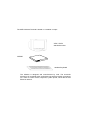
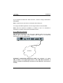
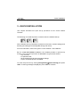
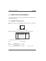
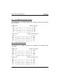
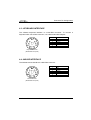
AX3000 Platine Terminal
Ethernet TCP/IP
Models 65B
Installation Guide
March 2004 - Ref: I65BE0303-1
Model AX3000/M65B
The reproduction of this material, in part or whole, is strictly prohibited. For
additional information, please contact:
14 Avenue du Québec
Bât. K2 EVOLIC - BP 728
91962 Courtabœuf cedex - FRANCE
Tel.: 33 1.69.28.27.27
Fax: 33 1.69.28.82.04
Email: [email protected]
The information in this document is subject to change without notice. AXEL
assumes no responsibility for any errors that may appear in this document.
All trademarks and registered trademarks are the property of their respective
holders.
© - 2004 - AXEL - All Rights Reserved.
1 - NOTICES ......................................................................................................1
1.1 - SAFETY NOTICES ................................................................................1
1.2 - EMC NOTICES ......................................................................................1
1.3 - PHYSICAL SPECIFICATIONS ..............................................................2
2 - INSTALLATION ...........................................................................................3
2.1 - DESCRIPTION.......................................................................................3
2.2 - INSTALLATION......................................................................................4
2.2.1 - Monitor and keyboard......................................................................4
2.2.2 - Ethernet Connection........................................................................5
2.2.3 - Auxiliary Ports..................................................................................6
2.2.4 - Power On.........................................................................................6
3 - QUICK INSTALLATION...............................................................................7
4 - CONNECTOR PIN ASSIGNMENTS ..........................................................10
4.1 - ETHERNET PORT RJ45 (LAN)...........................................................10
4.2 - SERIAL PORTS AUX1 AND AUX2 (RJ45) .........................................11
4.2.1 - RJ45-DB9 and RJ45-DB25 adaptors ............................................12
4.2.2 - Peripheral RJ45 cables .................................................................12
4.3 - KEYBOARD INTERFACE....................................................................13
4.4 - MOUSE INTERFACE...........................................................................13
4.5 - VIDEO INTERFACE.............................................................................14
4.6 - PARALLEL INTERFACE .....................................................................15
5 - PROBLEM SOLVING.................................................................................16
The AXEL AX3000 Terminal is based on a modular concept.
VGA / SVGA
standard monitor
AX3000
standard keyboard
The AX3000 is designed and manufactured by Axel. The terminal's
electronics is contained within a slim base unit which provides connections
for a VGA or SVGA monitor, keyboard, system printer, serial devices and
Ethernet network.
Notices
1 - NOTICES
1.1 - SAFETY NOTICES
y Do not attempt to fix a AX3000 component failure by opening the terminal
case. In case of hardware failure, contact your service representative.
y Check AC voltage from the wall outlet is inside 100-240 Volts range.
y Make sure to use a properly grounded AC power outlet (3 poles: phase,
neutral and ground with no resistance between neutral and ground pole).
y The wall outlets used must be reached easily and as nearest as possible to
the AX3000 Platine Terminal to connect or disconnect the power cords.
y Make sure to power off all devices before connecting or disconnecting any
one of them (keyboard and serial or parallel cables).
y To install and connect any peripherals, refer to the respective supplier
installation manuals.
y The internal sub-miniature fuse-link of the power supply must be replaced only
with the same type fuse specifications:
SCHURTER Type MSF250 1A 250V Quick-acting - low-breaking capacity
1.2 - EMC NOTICES
y In order to ensure compliance with European EMC regulations (EN 55022)
and FCC Part 15 rules, it is required that shielded cables be used when
interfacing with other devices (peripherals or computers). As described in
Chapter 2.1
y This equipment has been tested and found to comply with the limits for a
Class B digital device, pursuant to part 15 of the FCC Rules. These limits are
designed to provide reasonable protection against harmful interference in a
residential installation. This equipment generates, uses and can radiate radio
frequency energy and, if not installed and used in accordance with the
instructions, may cause harmful interference to radio communications.
Installation Guide - Models 65B
1
Notices
However, there is no guarantee that interference will not occur in a particular
installation. If this equipment does cause harmful interference to radio or
television reception, which can be determined by turning the equipment off
and on, the user is encouraged to try to correct the interference by one or
more of the following measures:
- Reorient or relocate the receiving antenna.
- Increase the separation between the equipment and receiver.
- Connect the equipment into an outlet on a circuit different from that to
which the receiver is connected.
- Consult the dealer or an experienced radio/TV technician for help
1.3 - PHYSICAL SPECIFICATIONS
y Operating temperature: 5 to 35 °C
y Humidity: 80° non condensing
y Power supply:
100 - 240 V
0,2 - 0,01 A
50 - 60 Hz
y Dimensions: 216x270x31 mm
y Weight: 1,35 Kg
.
2
Installation Guide - Models 65B
Installation
2 - INSTALLATION
This chapter provides information and instructions to install the AX3000 Model
65B.
2.1 - DESCRIPTION
A green LED, located on the face plate, indicates when the AX3000 is powered
on.
The AX3000 has the following connectors and switches on the rear panel:
- power switch,
- power connector for the AX3000,
- VGA or SVGA connector,
- PS/2 keyboard connector,
- PS/2 mouse connector,
- two auxiliary serial ports: RJ45 (AUX1 and AUX2),
- auxiliary parallel port: female 25-pin (PARALLEL),
- TCP/IP port: RJ45 (LAN).
8
On/Off
9
1
Power inlet
VGA
Power Inlet:
100 - 240 V~
0.2 - 0.1 A
50 - 60Hz
2
3
Keyboard Mouse
4
Safety Extra Low
1 - SVGA
2 - Keyboard
3 - Mouse
4 - Serial1
5 - Serial2
6 - Parallel
7 - LAN
Installation Guide - Models 65B
5
Serial1 Serial2
6
Parallel
7
LAN
Voltages (SELV) Connectors:
shielded
unshielded
unshielded
shielded
shielded
shielded
unshielded
3
Installation
2.2 - INSTALLATION
For safety reasons and to prevent component damage, do not apply power to
the AX3000 before connecting or disconnecting any cable. Do not plug in the
AX3000 power cord until all other connectors have been plugged in.
Make sure the AX3000 and monitor power switches are in the OFF (0) position
before connecting cables to the back panel.
2.2.1 - Monitor and keyboard
Plug in the VGA monitor cable, the AT-compatible keyboard cable and the
optional mouse cable to the dedicated connectors on the terminal back panel:
4
Installation Guide - Models 65B
Installation
If your keyboard is fitted with a DIN connector, connect it using a DIN-to-MiniDIN adaptor.
Note: a serial mouse can also be connected to the AUX2 port.
To comply with EMC regulations, the VGA signal cable must be shielded.
Note: when the terminal is installed in a cabinet or rack, it is essential to
maintain air circulation around the VGA/SVGA monitor.
2.2.2 - Ethernet Connection
Plug the RJ45 connector on the end of the 10BaseT cable into the socket
labeled LAN on the back of the AX3000 (see chapter 4.1 for technical
specifications and pin assignments).
ETHERNET
ETHERNET CONNECTION INDICATOR LIGHT: this indicator is a green
LED, located on the upper-right corner of the LAN RJ45 connector. It
lights to indicate a satisfactory connection to the Ethernet circuit (server
or hub).
Installation Guide - Models 65B
5
Installation
Note: if the green LED does not light, check that the Ethernet connector and
cable both comply with the specifications listed in chapter 4.1.
2.2.3 - Auxiliary Ports
AX3000 Models 65B have three auxiliary ports as a standard feature:
- AUX1:
bi-directional serial port, RJ45 connector,
- AUX2:
bi-directional serial port, RJ45 connector,
- PARALLEL: parallel port, female 25-pin connector.
Cable pin assignments are listed in chapter 4.
To comply with EMC regulations, the serial cables must be shielded.
2.2.4 - Power On
Connect the AX3000 and the VGA power cords to earthed main power sockets.
The green LED on the front of the terminal should light, and a single audible
beep should be heard, to indicate that the AX3000 terminal is powered up and
operating correctly.
To indicate correct keyboard initialization after power-up, the keyboard indicator
lights 'Num lock', 'Caps lock' and 'Scroll lock' should flash twice.
The green LED on the right side of the RJ45 connector on the back panel
remains lit, to indicate a satisfactory Ethernet connection.
If the terminal does not function as described above (for example if it emits a
continuous tone sound, or two beeps, or if an error message is displayed on the
screen) refer to chapter 5. If the terminal still does not operate properly, call
your service representative.
6
Installation Guide - Models 65B
Quick Installation
3 - QUICK INSTALLATION
This chapter describes the quick set-up procedure for the TCP/IP Platine
Terminal.
The following command sequence is used to enter the AX3000 Set-Up:
All the AX3000 set-up parameters (network environment, session settings and
auxiliary port settings) can be adjusted through this set-up.
For more information, refer to the guide: TCP/IP AX3000 - User's Manual.
But, for a fast and reliable installation, the AX3000 provides a quick set-up
function. This quick set-up function is dedicated to a typical environment:
- only one host,
- an optional router,
- all the virtual terminals have the same settings,
- a lpd or a Prt5250 printer is available.
To enter the quick set-up, select [Configuration]→[Quick Set-up] and press
<CR>. A warning message is displayed, press <CR> to continue.
Installation Guide - Models 65B
7
Quick Installation
The quick set-up dialog box is displayed:
Note: this box is automatically called when the AX3000 is powered up for the
first time.
Quick set-up parameters:
- Keyboard: keyboard nationality.
- Number of sessions: maximum number of sessions. These sessions
are automatically associated with the host described above.
- Configuration: virtual terminal settings. This choice is selected from a
list.
- Enable DHCP: two possible values:
- yes: the DHCP protocol is run when the set-up is exited. The
DHCP function is automatically set to get both the AX3000 IP
address and other DHCP options (netmask, default router, etc).
- no: parameters are manually entered (in addition, AX3000 Name
(FQDN) is not accessible).
- AX3000 IP address: it must be entered if DHCP is disabled.
- Default router: optional router IP address.
- 1st DNS Server IP Address: optional DNS server IP address
- AX3000 Name (FQDN): this optional parameter (see appendix A.5)
allows an AX3000 to be identified by this name if both a DHCP server
and a Dynamic DNS server are available.
- Host Name: if the IP address of a host is not given, this name will be
resolved by DNS (if a DNS server is given).
8
Installation Guide - Models 65B
Quick Installation
- Host IP address: if this field is left blank, DNS will be used to resolved
the hostname.
- Enable: Configuring printers attached to AX3000. If ‘Pre-defined
Configuration’ is set to 5250 and a hostname is defined, PRT5250 (telnet
printing) is automatically selected. If not LPD is the default printing
system. This setting can easily be changed through interactive set-up.
- Printer Name (accessible only if "Enable" is set): this is the printer name
at the operating system level.
- Manufacturer Type and Model (accessible only with Prt5250): printer
type and model.
After confirmation, all the AX3000 set-up parameters are updated.
Installation Guide - Models 65B
9
Connector Pin Assignments
4 - CONNECTOR PIN ASSIGNMENTS
This chapter describes the connector pin assignments for the different ports of
the AX3000 Models 65B.
4.1 - ETHERNET PORT RJ45 (LAN)
Recommended wiring is a non-shielded twisted-pair cable (UTP), category 3
or 5
1 2 3 4 5 6 7 8
RJ45 connector (Models 65B rear panel)
Note: the maximum length of a 10BaseT cable is 100 meters (330 feet).
Pin
1
2
3
4
5
6
7
8
Signal Name
TX+ (Transmitted Data)
TX- (Transmitted Data)
RX+ (Received Data)
----RX- (Received Data)
-----
Direction
Input
Input
Output
----Output
-----
a - AX3000 Connected to a HUB
HUB
RX+
RXTX+
TX-
10
AX3000
Models
65B
AX 3000
Model
55
1<
2<
3
6
(*)
1
2
>3
>6
TX+
TXRX+
RX-
(*) see the note on next page
Installation Guide - Models 65B
Connector Pin Assignments
b - AX3000 Connected to an Ethernet Controller
Ethernet Board
TX+
TXRX+
RX-
AX3000
AX3000
ModelsModel
65B 55
1
2
3<
6<
1
2
>3
>6
TX+
TXRX+
RX-
IMPORTANT: the cable is composed of two twisted pairs. The two wires
TX+ / TX- must belong to one pair and the two wires RX+ / RX- must
belong to the other pair.
4.2 - SERIAL PORTS AUX1 AND AUX2 (RJ45)
These serial ports are bi-directional ports (for printers, bar-code readers, touch
screens, etc):
1 2 3 4 5 6 7 8
AUX1 and AUX2 connectors
(Models 65B rear panel)
Pin
1
2
3
4
5
6
7
8
Signal Name
RTS (Request To Send)
DTR (Data Terminal Ready)
RD (Received Data)
SG (Signal Ground)
CTS (Clear to Send)
TD (Transmitted Data)
--DCD (Data Carrier Detected)
Installation Guide - Models 65B
Direction
Output
Output
Input
--Input
Output
--Input
11
Connector Pin Assignments
4.2.1 - RJ45-DB9 and RJ45-DB25 adaptors
Pin assignment for an adaptor between the peripheral cable and the AX3000
RJ45 connector:
AX3000 - RJ45
DTR
RD
SG
CTS
TD
2
3<
4
5<
6
AX3000 - RJ45
DTR
RD
SG
CTS
TD
2
3<
4
5<
6
Adaptor - male 9-pin
>4
2
5
8
>3
DTR
RD
SG
CTS
TD
Adaptor - DTE female 25-pin
> 20
3
7
5
>2
DTR
RD
SG
CTS
TD
4.2.2 - Peripheral RJ45 cables
Pin assignment for a direct connection of a peripheral to the AX3000 RJ45
connector:
AX3000 - RJ45
DTR
RD
SG
CTS
TD
2
3<
4
5<
6
AX3000 - RJ45
DTR
RD
SG
CTS
TD
12
2
3<
4
5<
6
Peripheral - female 9-pin
>6
3
5
4
>2
DSR
TD
SG
DTR
RD
Peripheral - DTE male 25-pin
>6
2
7
20
>3
DSR
TD
SG
DTR
RD
Installation Guide - Models 65B
Connector Pin Assignments
4.3 - KEYBOARD INTERFACE
The AX3000 keyboard interface is a Mini-DIN connector. To connect a
keyboard which has a DIN connector, use a DIN-to-Mini-DIN adaptor:
Pin
6
5
4
3
2
1
1
2
3
4
5
6
Signal name
Data
--Ground
+ 5 V DC
Clock
---
Keyboard connector
(Models 65B rear panel)
4.4 - MOUSE INTERFACE
The AX3000 mouse interface is a Mini-DIN connector:
Pin
6
5
4
3
2
1
1
2
3
4
5
6
Signal name
Data
--Ground
+ 5 V DC
Clock
---
Mouse connector
(Models 65B rear panel)
Installation Guide - Models 65B
13
Connector Pin Assignments
4.5 - VIDEO INTERFACE
The AX3000 video interface is VGA and SVGA compatible:
5
4
10
15
3
9
14
2
8
13
1
7
12
6
11
VGA/SVGA connector
(Models 65B rear panel)
Pin
1
2
3
4
5
6
7
8
9
10
11
12
13
14
15
14
Signal name
Red
Green
Blue
--Ground
Ground
Ground
Ground
Ground
Ground
----Horizontal sync.
Vertical sync.
---
Installation Guide - Models 65B
Connector Pin Assignments
4.6 - PARALLEL INTERFACE
The AX3000 Models 65B are equipped with a parallel port.
13
12
25
11
24
10
23
9
22
8
21
7
20
6
19
5
18
4
17
3
16
2
15
1
14
Parallel connector
(Models 65B rear panel)
Pin
1
2
3
4
5
6
7
8
9
10
11
12
13
14
15
16
17
18
19
20
21
22
23
24
25
Signal Name
Strobe
Data 0
Data 1
Data 2
Data 3
Data 4
Data 5
Data 6
Data 7
ACK (Acknowledge)
Busy
PE (Paper End)
SLCT (Select)
Auto Feed XT
Error
Init
SLCT IN
Ground
Ground
Ground
Ground
Ground
Ground
Ground
Ground
Installation Guide - Models 65B
15
Problem Solving
5 - PROBLEM SOLVING
This chapter describes some of the problems, that may occur during installation
of the AX3000 Models 65B, and offers possible solutions.
Safety Warning! Under no circumstances should you attempt
to fix a Platine problem by opening the terminal case. High
voltages may be present even when the terminal is switched
off. Only qualified technicians should open the AX3000 case.
9 - THE VGA MONITOR VERTICAL SYNC IS LOST
Care must be taken with the VGA monitor. The default VGA frequency used by
the AX3000 is 72 Hertz. If the VGA monitor does not support this frequency, the
vertical sync will be lost. To fix this problem, either use a more modern monitor
or modify the AX3000 VGA frequency:
9 - GREEN FRONT INDICATOR DOESN'T LIGHT, OR NO BEEP WHEN
YOU PRESS POWER SWITCH
Check there is power at the wall outlet and power cord connections.
9 - CONTINUOUS TONE SOUNDS AFTER THE TERMINAL HAS BEEN
SWITCHED ON
This alarm indicates a hardware failure. Report the problem to your service
representative.
16
Installation Guide - Models 65B
Problem Solving
9 - AFTER THE TERMINAL HAS BEEN SWITCHED ON, THE MESSAGES
'NO ETHERNET BOARD PRESENT' AND 'CANNOT ATTACH
ETHERNET BOARD' APPEAR
This message indicates a hardware failure. Report the problem to your service
representative.
9 - A DOUBLE-BEEP SOUNDS
After switching on the terminal, a double beep may sound, a few seconds after
the normal first beep.
This signal indicates that keyboard initialization has failed. Check the keyboard
connection to the terminal back panel.
It is possible for the keyboard to function correctly, despite this double-beep
signal. As a quick test of keyboard operation, enter set-up mode by pressing the
<Ctrl><Alt><Esc> keys simultaneously. If set-up mode is working, you can
ignore the double beep signal and use the terminal normally.
9 - ETHERNET CONNECTION INDICATOR DOES NOT LIGHT
This indicator is the green LED located next to the network connector on the
terminal back panel.
Failure to light when the terminal is switched on may be due to any of the
following:
- the Ethernet cable is disconnected at the far end,
- the device (host or hub), to which the network cable is connected, is not
switched on,
- there is a fault on the Ethernet cable or the cable is wired with incorrect
pin assignments.
Installation Guide - Models 65B
17
Problem Solving
9 - NO LOGIN WHEN THE 'CONNECTING...' MESSAGE IS DISPLAYED
Check the Ethernet cables are correctly connected and networked devices
(hubs or servers) are switched on.
No connection (and no login) can also be due to a wrong terminal setting during
the TCP/IP set-up (for example a wrong IP address).
9 - INCORRECT APPEARANCE OF SOFTWARE DISPLAYED ON THE
AX3000
Check the values of parameters set using Terminal Set-Up. Check that the
correct terminal emulation has been chosen.
Check that the TERM environment variable (for the current UNIX shell)
corresponds to the emulation selected for the terminal (in AX3000 Set-Up).
9 - THE CONNECTED PRINTER DOES NOT WORK
Check that the cable pin assignment is correct and test the printer in local mode
by selecting the [TEST] button within the auxiliary port dialog box.
18
Installation Guide - Models 65B
14 Avenue du Québec
Bât. K2 EVOLIC - BP 728
91962 Courtabœuf cedex - FRANCE
Tel.: 33 1.69.28.27.27
Fax: 33 1.69.28.82.04
Email: [email protected]