1
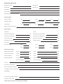
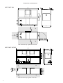
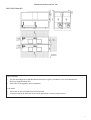
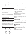
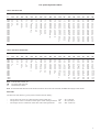
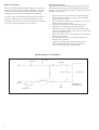
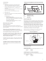
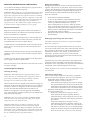
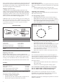
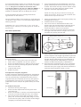
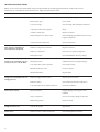
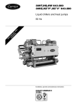
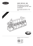
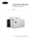
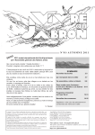
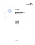
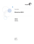
30GV/30GY 020-059
Air-Cooled Liquid Chillers
50 Hz
Installation, Operation and Maintenance Instructions
1
CONTENTS
Page
Start-up checklist .......................................................................................................................................................................... 3
Dimensions and clearances .......................................................................................................................................................... 4
Physical and electrical data ......................................................................................................................................................... 6
Application data ............................................................................................................................................................................ 7
Minimum and maximum cooler water flow rates .......................................................................................................................... 7
Minimum operating temperature .................................................................................................................................................... 7
Water loop volume ......................................................................................................................................................................... 7
Installation ..................................................................................................................................................................................... 7
Safety considerations .................................................................................................................................................................... 7
Preliminary checks ......................................................................................................................................................................... 8
Moving and lifting the unit ............................................................................................................................................................. 8
Positioning of 30GV, GY 044-059 units ........................................................................................................................................ 8
Duct connections ............................................................................................................................................................................ 8
Fan module ..................................................................................................................................................................................... 9
Fan speed adjustment tables ........................................................................................................................................................... 9
Fan laws .......................................................................................................................................................................................... 9
Water connections ...................................................................................................................................................................... 10
Power supply ............................................................................................................................................................................... 12
Electrical checks ........................................................................................................................................................................... 12
Start-up ........................................................................................................................................................................................ 12
Preliminary checks ....................................................................................................................................................................... 12
Actual start-up .............................................................................................................................................................................. 13
Electromechanical control ............................................................................................................................................................ 13
Set point adjustment ..................................................................................................................................................................... 13
Control pressostats ........................................................................................................................................................................ 13
Servicing refrigeration components .......................................................................................................................................... 14
General maintenance .................................................................................................................................................................... 14
Liquid refrigerant charging ........................................................................................................................................................... 14
Compressors ................................................................................................................................................................................. 15
Compressor motor protection ...................................................................................................................................................... 15
Heat exchangers ............................................................................................................................................................................ 15
Evaporator .................................................................................................................................................................................... 15
Condenser coil .............................................................................................................................................................................. 16
Fan motor replacement ................................................................................................................................................................. 17
Troubleshooting chart ................................................................................................................................................................ 18
START-UP CHECK LIST
Equipment sold by:
Contract No.:
Installed by:
Contract No.:
Site address:
Start-up date:
Equipment type and serial numbers:
Electrical data:
Supply voltage:
Ph.
Nominal voltage:
V
Current draw:
Ph. 1
V
Ph. 2
V
Ph. 3
V
A
Ph. 3
A
% network voltage:
A
Ph. 2
Main circuit breaker rating:
A
Physical data:
Condenser:
Cooler:
Entering air temperature:
°C
Entering water temperarture:
°C
Leaving air temperature:
°C
Leaving water temperature:
°C
Pressure drop (air):
kPa
Discharge air pressure:
Pa
Fan speed:
Pressure drop (water):
kPa
Suction pressure:
kPa
r/s or rpm
Fan motor input:
Ph. 1
V
Ph. 2
V
Ph. 3
V
Ph. 1
V
Ph. 2
V
Ph. 3
V
Safety device setting:
High pressure switch:
cut-out
kPa:
cut-in
kPa
Low-pressure switch:
cut-out
kPa
cut-in
kPa
Safety thermostat:
cut-out
°C
cut-in
°C
Control thermostat:
cut-out first step
°C
cut-in first step
°C
cut-out second step
°C
cut-in second step
°C
Oil level:
Oil visible in sight glass?:
Colour of moisture indicator:
Air bubbles visible in sight glass?:
Accessories:
Commissioning engineer (name):
Purchase order number:
NOTE: Please fill in this sheet during the installation
Dimensions and clearances
30GV/30GY 020
36
36
1868
36
2103
800
915
A
600
800
950
B
A-B: Clearance only required on one side
30GV/30GY 025-035
36
36
2028
36
3327
600
800
983
A
1800
800
950
B
A-B: Clearance only required on one side
4
Dimensions and clearances, mm
36
36
2028
36
36
30GV/30GY 044-059
2000
1000
3327
1800
950
1000
1800
Alternative 1
Alternative 2
Floor mounting
•
•
For unit mounting holes, weight distribution and centre of gravity coordinates, refer to the dimensional
drawings supplied with the unit.
These units are designed for indoor installation.
CAUTION:
•
•
Ensure the air flow around the unit is not obstructed.
At least one side of the units must be free from obstructions, to ensure proper air flow.
5
Physical data
30GV/30GY
020
025
030
035
044***
049***
059***
Nominal cooling capacity 30GV* kW
Nominal cooling capacity 30GY* kW
51
50
66
69
73
97
97
101
132
138
146
153
193
202
Operating weight
kg
850.0
1030.0
1100.0
1250.0
2111.5
2255.0
2562.5
Refrigerant charge****
kg
9.8
14.5
15.2
17.0
29.0
29.0
34.0
1/2**
66/100
1/2**
66/100
1/1
3
33/66/100
1/1
3
33/66/100
1/1
3
33/66/100
31.0
43.0
62.0
62.0
86.0
2 FPT
2 MPT
1000
2 FPT
2 MPT
1000
3 FPT
3 FPT
1000
3 FPT
3 FPT
1000
3FPT
3FPT
1000
6900
10.53
4.5
24.2
Two, double centrifigal
11200
11200
10.33
10.67
2 x 4.0
2 x 4.0
24.2
24.2
Compressor
Quantity
Circuit A/B
No. of capacity steps
Capacity control
Semi-hermetic, 4 or 6 cylinders, 24.2 r/s
%
1/2
50/100
1/2**
66/100
Evaporator
Net water volume
l
Water connections
in
Inlet
Outlet
Max. water side operating pressure kPa
Coaxial
Shell-and-tube
21.7
31.0
BSPC, conical gas, ISO R7
2-1/2 MPT
2 FPT
2-1/2 MPT
2 MPT
1000
1000
Condenser
Condenser fan
Nominal air flow
Speed at 150 Pa ESP
Nominal fan motor power
Motor speed
Copper tubes, al;uminium fins
Single centrifugal Double centrifugal
3500
5600
5600
10.33
10.33
10.67
3.0
4.0
4.0
24.2
24.2
24.2
l/s
r/s
kW
r/s
13800
10.83
2 c 4.5
24.2
*
Based on 12°C/7°C entering/leaving chilled water temperature, 35°C condenser entering air temperature and nominal fan speed.
** 3 steps with capacity reduction accessory
*** Supplied as two separate units as follows, with all electrical, hydraulic and mechanical components necessary for installation: size 044 = 2 x size 025, size 049 = 2 x
size 030, size 059 = 2 x size 035
**** 30GY units use refrigerant R-22, 30GV units use R-407C. The refrigerant charge shown is guidelines only. Always refer to the nameplate.
Electrical data
30GV/30GY
Standard unit
Fan
150 Pa
300 Pa (optional)
V-ph-Hz
RLA
XL
ICF
PW
ICF
kW
FLA
kW
FLA
020
230-3-50
400-3-50
62
36
263
180
163
111
3.7
3.7
11.7
6.3
4.9
4.9
15.7
9.0
025
230-3-50
400-3-50
84
48
359
232
222
143
4.9
4.9
15.7
9.0
8.8
8.8
26.4
15.2
030
230-3-50
400-3-50
94
54
383
262
237
161
4.9
4.9
15.7
9.0
8.8
8.8
26.4
15.2
035
230-3-50
400-3-50
135
77
564
356
346
218
5.5
5.5
17.9
10.3
8.8
8.8
26.4
15.2
044
230-3-50
400-3-50
167
96
442
280
305
191
9.8
9.8
2 x 15.7
2 x 9.0
17.6
17.6
2 x 26.4
2 x 15.2
049
230-3-50
400-3-50
187
108
476
316
330
215
9.8
9.8
2 x 15.7
2 x 9.0
17.6
17.6
2 x 26.4
2 x 15.2
059
230-3-50
400-3-50
270
154
699
433
808
295
11.0
11.0
2 x 17.9
2 x 10.3
17.6
17.6
2 x 26.4
2 x 15.2
Legend:
FLA
- Full load amperes
ICF
- Maximum instantaneous current flow, A (compressors)
kW
- Maximum fan motor power input
RLA
- Rated load amperes (compressors)
PW
- Part-winding astart (compressors)
XL
- Across-the-line-start (compressors)
Note: To obtain the maximum unit current, add the compressor maximum currecnt (RLA) to the fan motor current (FLA).
6
APPLICATION DATA
INSTALLATION
Minimum and maximum evaporator water flow rates
30GY/GV
Min flow rate, l/s
Max. flow rate, l/s
020
025
030
035
044
049
059
1.2
1.6
1.6
2.4
3.2
3.2
4.8
4.8
8.0
8.0
9.4
16.0
16.0
18.4
Installation, start-up and servicing this equipment can be
hazardous due to system pressures, electrical components and
equipment location (roofs, elevated structures, etc.).
Only trained, qualified installers and service mechanics should
install, start-up and service this equipment.
Minimum operating temperature
°C
Single-speed motor
Two-speed motor
Dampers
SAFETY CONSIDERATIONS
14
4
-20
Untrained personnel can perform basic functions, such as
cleaning coils. All other operations should be performed by
trained service personnel.
When working on the equipment, observe precautions in the
literature, and on tags, stickers, and labels attached to the
equipment.
Maximum chilled water flow rate
The maximum chilled water flow (>0,09 l/s per kW or <2.8 K
temperature difference) is limited by the maximum permitted
pressure drop in the evaporator.
Water loop volume
Whatever the size of the system, the water loop minimum
volume is given by the following formula:
Volume = CAP (kW) x N* = litres
where CAP is the nominal system capacity (kW) at the nominal
operating conditions of the installation.
Application
N*
Air conditioning
Industrial process cooling
Low temperature operation
3.25
6.5
10.8
•
•
•
Follow all safety codes.
Wear safety glasses and work gloves.
Use care in handling, rigging and setting down bulky
equipment.
WARNING: Before doing any work ensure that the power
supply (400 V and 230 V) is disconnected, and switches and
isolators are opened and tagged.
During operation some parts of the unit reach or exceed
temperatures of 70°C (e.g. compressor discharge side,
discharge line). Only trained and qualified engineers, aware of
these hot surfaces, are allowed to perform maintenance
operations.
Preliminary checks
This volume is necessary for stable operation and accurate
temperature control.
It is often necessary to add a buffer water reservoir to the
circuit in order to achieve the required volume. The reservoir
must itself be internally baffled in order to ensure proper
mixing of the liquid (water or brine). Refer to the examples
below.
NOTE: The compressor must not restart more than 10 times in
an hour.
Check equipment received
•
Inspect the unit for damage or missing parts. If damage is
detected, or if shipment is incomplete, immediately file a
claim with the shipping company.
•
Confirm that the unit received is the one ordered.
Compare the nameplate data with the order.
•
Confirm that all accessories ordered for on-site installation
have been delivered, and are complete and undamaged.
Moving and lifting the unit
Moving
Do not remove skids, pallets or protective packaging until the
unit is in its final position. Move the chiller using tubes or
rollers, or lift it, using slings of the correct capacity. Before
moving the unit, ensure that all panels are correctly fixed.
Lifting
Refer to dimensional drawings 99 DI-035 GY 500 250E and
the lifting instructions label on the unit.
Bad
Good
Bad
Good
7
Preliminary checks
Before installing and connecting the unit check:
The required clearances for correct unit operation and
maintenance.
Size and location of the chilled water piping.
Location and electrical characteristics of the available
power supply which must agree with the unit nameplate
rating.
Location and correct installation of the ductwork.
That there is not only sufficient space for routine service
and maintenance work, but also for operations such as: fan
shaft inspection, compressor removal etc. Refer to the
certified drawings for the units.
Positioning
Once the unit has been installed in its final location, remove the
skids, level the unit with a spirit level and bolt it to the floor or
to a pad.
CAUTION: These units must not be installed outside, except
under cover.
If it is necessary to locate the unit on an upper floor, be sure
that the structure is designed to support the weight. If required,
strengthen the floor. Also ensure that the installation surface is
level. Check the dimensional drawing for unit dimensions and
weight distribution.
Positioning of the 30GV/GY 044-059 units
Mechanical connection
Step 1
-
6-7
5
First position unit B (the control box of this unit does not
include a disconnect switch).
Fasten beams 2 and 3 with screw 6 and washer 7 to unit B.
Move unit A close so that it can be fastened to beams 2
and 3 from the inside of the unit.
6-7
4
4
Unit A
Unit B
3
1
6-7
Duct connections
The fan motor assembly is mounted on a self-supporting frame,
and permits connection to a ductwork system without using
additional flexible connections.
Suction side
When designing ducts, the possible installation of accessory
filters and air dampers must be taken into consideration. For
30GV,GY 044-059 units it is preferable to leave the two
suction openings free. The units will also function correctly
with only one suction opening. In this case it is necessary to
increase the fan speed of the rear unit (in this case unit B) by
8% in relation to the front unit (unit A with direct air intake, in
order to balance the air flows for the two modules.
Discharge side
For units 30GV,GY 025-035 the selection curves are based on
a connection separated by two ducts (four for 30GV, GY 044
to 059). If this is not the case, the additional pressure, which is
due to the change in the dynamic pressure, must be taken into
account (see table below).
CAUTION: The following rules for centrifugal fans must
always be adhered to, in order to ensure that the maximum
power input of the motor is not exceeded:
The fan must not be rotated without the panels being fitted.
The unit should not be operated without a discharge duct.
Use panels to ensure that the suction or discharge opening
cannot obstructed (e.g. bottom supply or opening of doors).
Unit B
Minimum outdoor operating temperature (°C)
2
3
2
6-7
2
2
3
Step 2
-
-
8
Fasten panel 4 to the front of the assembly using screws 6
and washers 7, and panel 5 to the rear of the assembly
using screws 6 and washers 7.
Fasten the control box to front panel 4, which was
previously fastened with screws 6 and washers 7.
Unit size
020
025-059
% load
Single-speed motor
Two-speed motor
Dampers
100
10
0
-20
50
12
2
-20
100
10
0
-20
66
12
2
-20
33
14
4
-20
Fan module
Before the final start-up of the unit, check that the ductwork is
correctly attached to the unit. After checking the correct
positioning of the pulley elements on the shaft and the belt
tension, the fan motor must be switched on, as follows:
1. Check the rated motor current on the nameplate.
2. Check that all panels are fitted.
3. Start the fan motor using a contactor. Measure the current. If
the value is higher than the value established in step 1, or
more than 15% below that value, it may be necessary to
adjust the fan speed as shown in the following tables:
Fan speed adjustment tables
30GV and 30GY 020
Air flow 6 r/s
7 r/s
8 r/s
9 r/s
10 r/s
11 r/s
12 r/s
13 r/s
14 r/s
l/s
ESP
kW
ESP
kW
ESP
kW
ESP
kW
ESP
kW
ESP
kW
ESP
kW
ESP
kW
ESP
kW
1900
2100
2300
2500
2700
2900
3100
3300
3500
3700
3900
4100
4300
4500
4700
4900
5100
5300
61
52
40
27
12
0
0.6
0.7
0.8
0.8
0.9
97
89
79
67
53
37
20
1
0.9
1.0
1.1
1.2
1.3
1.4
1.4
137
130
121
110
98
83
67
50
30
8
0
1.1
1.3
1.4
1.5
1.6
1.8
1.9
2.0
2.1
2.2
180
174
167
157
146
133
118
102
84
63
42
18
0
1.4
1.6
1.7
1.8
2.0
2.1
2.3
2.4
2.6
2.7
2.9
3.0
226
222
216
208
198
186
173
158
141
122
101
79
55
29
1
1.7
1.8
2.0
2.2
2.4
2.5
2.7
2.9
3.1
3.2
3.4
3.6
3.8
3.9
277
274
269
262
253
243
231
217
201
184
165
144
121
96
70
41
11
0
1.9
2.1
2.3
2.5
2.7
2.9
3.1
3.3
3.5
3.7
3.9
4.1
4.4
4.6
4.8
5.0
5.2
330
329
325
320
312
303
293
280
266
250
232
212
190
167
142
115
86
55
2.2
2.4
2.6
2.9
3.1
3.3
3.6
3.8
4.0
4.2
4.5
4.7
4.9
5.2
5.4
5.6
5.9
6.1
388
387
385
381
375
367
358
347
334
319
302
284
263
241
217
192
164
135
2.4
2.7
3.0
3.2
3.5
3.7
4.0
4.2
4.5
4.8
5.0
5.3
5.5
5.8
6.0
6.3
6.5
6.8
445
446
445
442
437
431
425
413
401
388
372
355
336
316
293
269
243
215
2.7
3.0
3.3
3.5
3.8
4.1
4.4
4.7
5.0
5.3
5.5
5.8
6.1
6.4
6.7
7.0
7.2
7.5
30GV and 30GY 025-030-035
Air flow 6 r/s
7 r/s
8 r/s
9 r/s
10 r/s
11 r/s
12 r/s
13 r/s
14 r/s
l/s
ESP
kW
ESP
kW
ESP
kW
ESP
kW
ESP
kW
ESP
kW
ESP
kW
ESP
kW
ESP
kW
3000
3500
4000
4500
5000
5500
6000
6500
7000
7500
8000
8500
9000
9500
10000
10500
60
52
41
28
12
0
0.9
1.1
1.3
1.4
1.6
89
83
74
62
47
30
10
0
1.2
1.4
1.6
1.8
2
2.2
2.4
122
117
109
99
86
70
52
31
7
0
1.5
1.7
2
2.2
2.5
2.7
2.9
3.2
3.4
157
153
147
138
127
113
96
77
55
30
2
1.8
2.1
2.4
2.7
2.9
3.2
3.5
3.8
4.1
4.4
4.7
194
193
188
181
171
158
143
125
105
81
56
27
0
2.0
2.4
2.8
3.1
3.5
3.8
4.2
4.6
4.9
5.3
5.6
6
235
235
232
226
217
206
193
176
157
136
111
85
55
23
0
2.3
2.7
3.2
3.6
4
4.5
4.9
5.3
5.8
6.2
6.6
7.1
7.5
7.9
278
279
278
274
267
257
245
230
213
193
170
145
117
86
53
17
3.1
3.6
4.1
4.7
5.2
5.7
6.2
6.7
7.3
7.8
8.3
8.8
9.3
9.9
10.4
10.9
324
327
327
324
319
311
300
287
271
253
231
208
181
152
120
86
3.7
4.3
4.9
5.5
6.1
6.8
7.4
8
8.6
9.2
9.8
10.4
11
11.7
12.3
12.9
373
377
379
378
374
367
358
347
332
315
296
273
248
221
190
158
4.3
5
5.8
6.5
7.2
7.9
8.6
9.4
10.1
10.8
11.5
12.2
12.9
13.7
14.4
15.1
ESP
kW
r/s
External static pressure, Pa
Fan motor power input, kW
Revolutions per second
Note : As units 30GV and 30GY 044 to 059 are two GV and GY 025 to 035 units connected, the tables above apply to them as well.
Fan laws
The fan laws state that for a given system resistance and air density:
-
The air flow rate varies as a direct function of the speed ratio:
Qv2
The pressure varies as a function of the square value of the speed ratio: P2
The output varies as a function of the cube value of the speed ratio:
Pa2
= Qv1 x N2/N1
= P1 x (N2/N1)2
= Pa1 x (N2/N1)3
9
Water connections
Refer to the certified dimensional drawings for the sizes and
positions of all water inlet and outlet connections. The water
pipes must not transmit any radial or axial force to the heat
exchangers or any vibration to the pipework or building.
The water supply must be analysed and appropriate filtering,
treatment, control devices, isolation and bleed valves and
circuits built in, as necessary. Consult either a water treatment
specialist or appropriate literature on the subject.
Operating precautions
The water circuit should be designed to have the least number
of elbows and horizontal pipe runs at different levels. Below
the basic checks to be done (see also the illustration of a typical
hydraulic circuit below).
•
•
•
•
•
•
•
•
•
Note the water inlets and outlets of the heat exchangers.
Install manual or automatic air purge valves at all high
points in the water circuit.
Use an expansion chamber or an expansion/relief valve to
maintain pressure in the system.
Install water thermometers in both the entering and
leaving water connections close to the evaporator.
Install drain valves at all low points to allow the whole
circuit to be drained. Connect a stop valve in the drain line
before operating the chiller.
Install stop valves, close to the evaporator, in the entering
and leaving water lines.
Use flexible connections to reduce the transmission of
vibration to the pipework.
Insulate all pipework, after testing for leaks, both to
reduce thermal leaks and to prevent condensation.
Cover the insulation with a vapour barrier.
Typical hydraulic circuit diagram
Control valve
Air vent
Flow switch
Flexible connection
Heat exchanger
Buffer tank
Fill valve
Pressure tap
Thermostat sleeve
Filter
Expansion tank
10
Drain
Water connections (30GY/GV 044-059)
There are two alternatives:
Water entering at the left of the duplex unit and leaving on
the right.
Water entering at the right of the duplex unit and leaving
on the left.
The water inlet must be on one evaporator, and the outlet on
the other one, in order to correctly balance the flow rates in the
evaporators. When installing and connecting the components
ensure that there is no leak at any of the connections (see
diagram below).
IMPORTANT: The heat exchanger can be damaged by frost in
winter. Depending on the atmospheric conditions in your area
you can:
Add ethylene glycol.
Increase the thickness of the insulation.
Never disconnect the evaporator heaters.
If the unit is not used for a prolonged period, empty the
the heat exchanger and add ethylene glycol. At the
beginning of the following season, again fill the unit with
water and an added inhibitor.
If auxiliary equipment is installed, the installer must
follow basic installation principles and ensure that the
minimum and maximum flow rates are not exceeded; the
values must be between the values given in the Physical
Data table.
Water connections (30GV/GY 044-059)
Second alternative
First alternative
Water inlet
Water outlet
Evaporator 2
Refrigerant inlet and outlet
Evaporator 1
Water outlet
Water inlet
Evaporator 2
Evaporator 1
Refrigerant inlet and outlet
11
Power supply
Start-up
The power supply must conform to the specification on the
chiller nameplate. The supply voltage must be within the range
specified in the electrical data table.
Preliminary checks
Never be tempted to start the chiller without reading fully, and
understanding, the operating instructions and without having
carried out the following pre-start checks :
For connections refer to the wiring diagram.
•
Electrical connections (30GY/GV 044-059)
Carry out the electrical connections between the control boxes
in accordance with the diagram below and with the wiring
diagram supplied with the unit; ensure that the cables are
routed through the conduits.
•
All cables are labeled A B C D and E F (option 70).
Electrical connections
Control box B
•
Control box A
•
1
•
•
D
D
A
C
C
B
•
B
•
A
WARNING: Operation of the chiller with an improper supply
voltage or with excessive phase imbalance constitutes abuse
which will invalidate the Carrier warranty. If the phase
imbalance exceeds 2% for voltage, or 1% for current, contact
your local electricity supply company at once and ensure that
the chiller is not switched on until corrective measures have
been taken.
•
•
•
•
•
Voltage phase imbalance (%) :
= 100 x max.deviation from average voltage deviation
Average voltage
Electrical checks
WARNING: Never switch off the power supply to the crankcase
heaters unless the chiller is out of service for a seasonal
shutdown or lengthy repair. The heaters must be re-energised
for at least 24 hours before the chiller is restarted.
a.
b.
c.
d.
e.
12
Switch the unit off.
Open the control circuit disconnect switch.
Check the transformer connections.
Ensure that the control circuit corresponds to the wiring
diagram for the unit.
Check that all electrical connections are secure at the
terminals, contactors, bus bars and compressor terminal
blocks.
•
•
•
Confirm that all crankcase heaters are working by feeling
all compressor crankcases. Every compressor has a 200 W
cartridge heater (see the wiring diagram). The heater
remains energised even when the chiller is shut down to
stop the lubricating oil from absorbing refrigerant.
Check the operation of all accessories - chilled water
circulating pumps, air handlers and other equipment
connected to the evaporator. Follow the individual
manufacturer's instructions for this equipment.
It is recommended to connect the auxiliary contact of the
water pump contactor to ensure maximum unit safety (see
wiring diagram delivered with the unit).
Fill the chilled water circuit with clean water, and an
inhibitor formulated specifically for this purpose, or fill it
with another non-corrosive fluid to be chilled.
Purge air at all high points in the system. If water
temperatures below 5°C are likely, add the appropriate
volume of ethylene glycol to prevent freezing.
Confirm that the suction and discharge line stop valves are
fully opened.
Open the refrigerant line valves. Check again that the
water circuit valves are open.
Check that oil is visible in each compressor sight glass to
between 1/8 and 3/8 of the total glass depth (check for all
compressors).
Confirm that there are no refrigerant leaks.
Confirm that all crankcase heaters are firmly in place, and
check the secure positioning of all control sensors.
Confirm that discharge muffler securing bands and
discharge line connections are tight.
Check that all electrical connections are secure.
Turn the fan shafts by hand to ensure that they rotate
freely. Check the stability of the fan wheels on the shafts.
Check the tightness of the fan shaft bearing mounts. All
fan bearings are lubricated with lithium grease for a rated
minimum life of 40,000 hours.
Check the alignment of the motor and fan pulleys.
Belt tension: too little will allow the belts to slip on the
pulley, too much will put the bearing under stress.
At the start-up observe the fan and verify that its rotation
is correct, as indicated by the arrow on the scroll. To
reverse the rotation, interchange any two of the three
phases in the junction box of the motor.
Actual start-up
IMPORTANT:
•
Commissioning and start-up of the chiller must be
supervised by a qualified refrigeration engineer.
•
Start-up and operating tests must be carried out with a
thermal load applied and water circulating in the
evaporator.
•
All set point adjustments and control tests must be carried
out before the unit is started up.
•
Please refer to the controls manual for the unit.
a.
b.
Start up the unit.
Check that all safety devices are satisfied, paticularly the
high pressure switches.
For this purpose:
Stop the condenser fans.
Operate the machine until the high pressure switch
trips and verify that the pressure does not exceed the
cut-out value of 2900 kPa.
Using the control point as a reference, verify the
correct operation of the unit.
Electromechanical control
Multi-step thermostat
This consists of a series of load switches actuated by the
pressure developed inside a temperature sensing bulb, installed
in the cooler inlet.
Before replacing the bulb, half fill the well with a heat
conducting sealing compound. Replace the sensor in the well
recess. The thermostat is factory-set to control from the return
water temperature through a cooling range of 5.6 K.
The sequence switches are factory-calibrated and sealed
and should not need any field calibration. Two steps on
30GV and 30GY 020 to 035 and three steps on 30GV and
30GY 044 to 059 are available.
Design set point adjustment (three-step thermostat)
Temperature
drop
Temperature
rise
F
0
RY3
RB3
F
0
0
F
RY2
RB2
A
RY2
RB2
RY1
RB1
B
0
F
Set point
Differential between stages
Differential on one contact
Thermostat contact reference
Open contact
Closed contact
Set point adjustment
When the unit is ready for operation, insert a small screwdriver
in the adjusting slot to turn the dial (the dial may also be turned
by hand). Rotate the screwdriver, until the design set point for
the installation appears directly under the pointer. Insert a
thermometer in the return water connection and allow the unit
to run through a complete cycle. When switch No. 1 opens, the
last capacity step appears directly under the pointer. Read the
temperature. If it is not the same as the dial reading, it can be
compensated by shifting the control point slightly.
NOTE: Do not force the dial past the stop. This could cause
loss of the control point and damage the instrument.
Set point adjustment
Pointer
Adjusting slot
Stop
WARNING: Alteration of factory settings other than the design
set point, without the manufacturer's authorization, may void
the warranty.
If a different return water range or leaving water control is
specified, or if brine is to be used, the controller must be
changed. Consult your local Carrier representative for the
proper control.
F
0
0
F
RY1
RB1
Legend:
A
B
R, Y, B O
F
-
RY3
RB3
Set points
Calibrated dial
Control pressostats
Low pressure switch
Switches the unit off, if the evaporating temperature is too low:
Cut-out:
200 kPa
Cut-in:
350 kPa
Condensing pressure switch (2-speed option)
Energizes and de-energizes the second fan speed as a function
of the condensing pressure:
Cut-out:
1700 kPa
Cut-in:
1090 kPa
13
SERVICING REFRIGERATION COMPONENTS
Any technician attending the machine for any purpose must be
a fully qualified refrigeration engineer.
WARNING: Before doing any work on the machine ensure that
the power is switched and locked off and that all isolators are
tagged. If a refrigerant circuit is opened, it must be evacuated,
and recharged, after ensuring that the refrigerant is clean and
free from impurities, the filter-drier has been changed and the
unit has been tested for leaks. Before any operation on a
refrigerant circuit, the complete unit refrigerant charge must
be removed with a refrigerant charge recovery group.
Refrigerant guidelines
Refrigeration installations must be inspected and maintained
regularly and rigorously by specialists. Their activities must be
overseen and checked by properly trained people. To minimise
discharge to the atmosphere, refrigerants and lubricating oil
must be transferred using methods which reduce leaks and
losses to a minimum.
•
•
•
General maintenance
•
Keep the unit itself and the space around it clean and free of
obstructions. Remove all rubbish such as packing materials, as
soon as the installation is completed.
•
Regularly clean the exposed pipework to remove all dust and
dirt. This makes detection of water leaks easier, and they can
be repaired before more serious faults develop.
Confirm that all screwed and bolted connections and joints are
secure. Secure connections prevent leaks and vibration from
developing.
Check that all insulation joints are securely closed and that all
insulation is firmly in place. Check all heat exchangers and all
pipework.
Confirm regularly that any phase imbalance in the three-phase
power supply is within acceptable limits.
Lubricate the hinges, locks and latches on the electrical control
box doors sparingly.
Liquid refrigerant charging
Checking the charge
WARNING: When adjusting the refrigerant charge always
ensure that water is circulating in the evaporator in order to
prevent any possibility of freezing up. Damage caused by
freezing is not covered by the product warranty.
30GV and 30GY units are shipped with a full normal charge of
refrigerant. Refer to the Physical Data table. If it is nevertheless
necessary to add more refrigerant, run the unit at full capacity
for some time and then add refrigerant until there are no
bubbles in the sight glass. This will generally mean adding
more refrigerant than would be needed to prevent bubbles from
being seen in the sight glass.
WARNING: To ensure proper operation of 30GV and 30GY
units there must be at least 5 K of subcooling as the liquid
refrigerant enters the expansion valve.
30GV and 30GY units use a halogen refrigerant. For your
information, please find below an extract from the official
publication dealing with the design, installation, operation and
maintenance of air conditioning and refrigeration systems and
the training of people involved in these activities, as agreed by
the air conditioning and refrigeration industry.
14
Leaks must be repaired immediately
A valve on the condenser liquid refrigerant outlet line
enables the refrigerant charge to be transferred to the
receiver provided specifically for this purpose.
If the residual pressure is too low to make the transfer
alone, a purpose-built refrigerant recovery unit must be used.
Compressor lubricating oil contains refrigerant. Any oil
drained from a system during maintenance must therefore
be handled and stored accordingly.
Refrigerant under pressure must never be discharged to
the atmosphere.
Recharging liquid refrigerant (30GV units)
CAUTION: 30GV 020 to 059 units are charged with liquid
HFC-407c refrigerant.
This non-azeotropic refrigerant blend consists of 23% R-32,
25% of R-125 and 52% R-134a, and is characterised by the fact
that at the time of the change in state the temperature of the
liquid/vapour mixture is not constant, as with azeotropic
refrigerants. All checks must be pressure tests, and the
appropriate pressure/temperature ratio table must be used for
the interpretation of the values.
Leak detection is especially important for units charged with
refrigerant R-407c. Depending on whether the leak occurs in
the liquid or in the vapour phase, the proportion of the different
components in the remaining liquid is not the same.
NOTE: Regularly carry out leak checks and immediately repair
any leak found.
Undercharge (30GV units)
If there is not enough refrigerant in the system, gas bubbles
appear in the moisture sight glass. There are two possiblities:
•
Small undercharge (bubbles in the sight glass, no
significant change in suction pressure).
After detection and repair the unit can be recharged.
The replenishment of the charge must be done in the
liquid phase at the liquid line. The refrigerant cylinder
must contain a minimum of 10% of its initial charge.
•
Significant undercharge (large bubbles in the sight glass,
drop in suction pressure).
Small units (charge below 20 kg per circuit).
After detection and repair completely drain the
refrigerant charge, using a refrigerant recovery unit,
then recharge completely, following the precautions
given above.
Large units (charge above 20 kg per circuit).
After detection and repair completely recharge the
unit as described above, operate it for a few minutes
and then let a specialist carry out a chromatographic
analysis to verify the composition of the blend (range:
R-32: 22-24%, R-125: 23-27%, R-134a: 50-54%).
Compressors
Checking the oil charge
Check the oil level and add or remove oil as necessary so that
the level is 1/8 to 3/8 up each sight glass with the compressors
running normally.
WARNING: Never open or disconnect any switch or circuit
breaker which will cut the supply to the heaters, unless the unit
is to be shut down for lengthy service or repair or for a
seasonal shut down. In all cases the heater must be energised
for at least 24 hours before a compressor is restarted.
Heat exchangers
WARNING: Use only oils which have been approved for use in
refrigeration compressors. Never use oil which has been
exposed to air.
Evaporator
Protection devices
Recommended oil:
30GV
Polyolester Mobil Oil EAL 68 for semihermetic
compressors
30GY
Mineral oil, Carrier specification No. PP 33-2
Suniso 3 GS (Sun Oil Co.)
Capella WF 32-150
Clavus G 32 (Shell Oil Co.)
Gargoyle Artic (Mobil Oil) - original charge
WARNING: All fixing devices and fittings which may have
been removed during servicing must always be replaced upon
completion of the work and before restarting the unit.
Tightening torques to be applied
Description
Diameter, mm
Torque, Nm
Discharge valve
Cylinder head
Suction and liquid line flange
Suction valve
M16
M12
M12
M16
135-140
75-87
75-87
135-140
Compressor motor protection
Circuit breaker
Calibrated, thermo-magnetic, manually reset circuit breakers
protect the compressors against locked rotors and excessive
current draw.
WARNING: Never bypass a circuit breaker or increase its
setting. If a circuit breaker trips, find out why it has done so
and correct the problem before resetting the breaker.
Freeze-up prevention thermostat
The evaporator is protected against loss of water and freeze-up.
The protection is provided by a thermostat installed in the unit.
Evaporator maintenance
Check that:
•
the insulating foam is intact and securely in place.
•
the cooler heaters are operating, secure and correctly
positioned.
•
the water-side connections are clean and show no sign of
leakage.
Tube-in-tube evaporator (size 020) - cleaning
In some applications, heat exchanger fouling can be very high,
for example when using extremely hard water. The heat
exchanger can be cleaned by circulating a cleaning solution.
Use a tank with a weak acid solution, 5% phosphoric acid or, if
the heat exchanger is frequently cleaned, 5% oxalic acid. Pump
the cleaning solution through the heat exchanger. For optimum
cleaning, the cleaning solution flow rate should be 1.5 times that
of the normal circulation rate, and the direction of flow should
be opposite to that of normal circulation. Afterwards rinse with
large amounts of fresh water, in order to remove all the acid,
before starting up the system again. Clean at regular intervals.
Cleaning in place
Heat exchanger
Weak acid
solution
Discharge gas thermostat (DGT)
A sensor in each compressor discharge line opens to shut down
the compressor if the discharge gas temperature exceeds the
preset level.
Cut out 146°C
Cut in 113°C
Crankcase heater
Each compressor is fitted with an electric resistance crankcase
heater which prevents any absorption of refrigerant by the
compressor lubricating oil when the compressor is shut down.
Each heater is held in place by a screw clip which must be
secure. Prolonged exposure of the heater to air will result in its
destruction. The heater is energized when the compressor is
switched off.
Multitube evaporators (30GV and 30GY 025-059)
The evaporator can be removed using the following procedure:
•
Close the chilled water supply and return valves (if
installed), and disconnect the chilled water supply and
return pipe connections.
•
Drain the water from the cooler.
•
Remove all temperature sensors from the cooler.
•
Fold back the insulation at the refrigerant line
connections.
When the evaporator heads and manifolds are removed, the
outer tube end plates will be visible.
15
Four evaporator tubes are swaged into the end plate and cannot
be removed. A dot punch mark in the end plate opposite each
one identifies each of them. If any of them develop a leak, the
tube must be plugged, as described below.
Plugging evaporator tubes
A leaking tube can be plugged pending replacement. The
number of tubes plugged will determine when they should be
replaced. Check with Carrier the effect upon chiller performance
of plugging a number of tubes. Carrier will need to know the
number of tubes to be plugged and their positions. The figure
below shows the Elliott method of plugging tubes.
WARNING: Take care when inserting plugs not to damage the
plate material between the tubes. Avoid excessive force. Clean
all components with Locquic N and then coat all surfaces with
several drops of Loctite 75 to ensure a good seal without
applying excessive force.
Preparation of gaskets
When rebuilding the cooler, new gaskets must always be used.
They must conform to the Carrier specification for compressed
gaskets.
•
Clean the gasket and its place on the tube sheet.
•
Cover the two matching surfaces (gasket and tube sheet)
Tightening cooler head bolts
Cooler head bolts must be tightened in the specified sequence
and to the correct torque.
Use this tightening sequence:
•
Hand tighten the four bolts as shown below in stage 1.
•
Hand tighten the next four bolts as shown below in stage 2.
•
Starting at the 12 o'clock position, and working clockwise,
insert and hand tighten the remaining outer bolts.
•
Insert and tighten the six screws in the centre of the head.
Bolt size M12 - 71-87 Nm
Bolt size M16 - 171-210 Nm
Bolt size M20 - 171-210 Nm
Elliott tube plug
Stage 1
Stage 2
7
1
5
4
3
6
2
8
30GV and 30GY
020-059
Components
Part number
Tube brass plug
Tube brass ring
---T-853--103500S-*
---T-853--002570S-*
Brass plug (holes without tubes)
Brass ring (holes without tubes)
---T-853--1031—S-*
---T-853--002631S-*
Loctite
Locquic
No. 75*
“N”*
•
•
•
•
Starting again at 12 o'clock and working clockwise,
tighten the outer bolts to the correct torque.
Not less than one hour later insert and tighten the six bolts
in the centre of the head, using the torque values given.
After the cooler has been refilled with clean refrigerant,
use a soap and water solution or an electronic detector to
confirm that there are no leaks.
Replace the evaporator insulation and temperature sensors.
*Order directly from your Carrier distributor
Replacing cooler tubes
Retubing must be done only by a properly trained service
engineer. Most standard practices can be applied, but for cooler
tubes a 5% crush allowance is made for tube expansion and
twisting (15.87 mm diameter tubes are used in these coolers).
The table below gives the specification of the materials used.
Example:
Tube sheet hole diameter
Tube outside diameter
Clearance
Tube inside diameter before rolling
Tube inside diameter after rolling
16.00 mm
15.87 mm
0.13 mm
14.27 mm
14.48 mm
NOTE: Tubes next to the gasket webs must be flush with the
tube sheets at either end of the cooler.
with adhesive, and stick them together.
•
Let the joint dry for 5 minutes.
•
Moisten the joint with a small amount of compressor oil.
•
Reinstall the evaporator head within 30 minutes.
16
Condenser coil
We recommend, that finned coils are inspected regularly to
check the degree of fouling. This depends on the environment
where the unit is installed, and will be worse in urban and
industrial installations and near trees that shed their leaves.
Proceed as follows:
•
Remove fibres and dust collected on the condenser face
with a soft brush.
•
Clean the coil with the appropriate cleaning agents.
We recommend TOTALINE products for coil cleaning:
Part No. P902 DT 05EE: traditional cleaning method
Part No. P902 CL 05EE: cleaning and degreasing.
These products have a neutral pH value, do not contain
phosphates, are not harmful to the human body, and can be
disposed of through the public drainage system.
Depending on the degree of fouling both products can be used
diluted or undiluted.
For normal maintenance routines we recommend using 1 kg of
the concentrated product, diluted to 10%, to treat a coil surface
of 2 m2. This process can either be carried out with a
TOTALINE applicator gun (part No. PE01 WA 4000EE) or
using a high-pressure spray gun. With pressurised cleaning
methods care should be taken not to damage the coil fins.
5.
6.
NOTE: Increasing the fan speed means increasing the
load on the fan motor. Do not exceed the maximum value
indicated in the Physical Data table.
If at all possible the direction of cleaning should be the
opposite of the air flow direction.
The two cleaning products can be used for any of the following
coil finishes: Cu/Cu, Cu/Al, Cu/Al with Polual, Blygold and/or
Heresite protection.
WARNING: Never use pressurized air or water, as this will
damage the fins, and always clean them against the normal air
flow direction.
Fan motor replacement
Using a straight-edge placed perdendicular to the motor
pulleys, mark the tip of each rim with a felt pen or a spot
of chalk. These marks will help count the number of turns.
Now unscrew each pulley flange the number of turns
required to obtain the required fan speed.
7.
Set the movable flanges at the nearest pulley hub key-way
and tighten the set screws.
8. Install the fan belts on the pulleys.
9. The correct tension is obtained when the belt can be
flexed 15 mm with one finger half way between the two
pulleys and without excessive effort. Check the belt
tension after three or four hours of operation.
10. After 24 to 48 hours of operation check the belt tension
once again. If the belt tension is to high or too low, this
will affect the operating lift of the belt.
Distance between centres L, mm
L
2
Deflection F, 15 mm
Load, kg
Proceed as follows:
1. Remove the fan access panel on the control box side.
2. Slide a sheet of cardboard over the coil to protect it.
3. Remove the damaged motor by sliding it from its support.
4. Fit the new motor by following the operation described
above in reverse order.
5. Adjust the belt tension.
6. Replace all panels.
Fan adjustment and pulley alignment
In order to obtain the optimum fan performance, the following
instructions should be carried out during the unit installation:
once the system ducting is installed and the static pressure
requirement has been calculated, the necessary fan speed can
be established by referring to the corresponding chart in the
product data. On new units, the fan speed is factory-set to mid
range.
To modify the fan speed:
1. Disconnect the unit power supply.
2. Remove the fan compartment enclosure panel on the
control box side.
3. Remove the fan belts. To do this, loosen the hexagonal fan
motor nut (ø 24 mm) and slide the motor on its support.
4. Move the fan motor forward and slip the belts over the
pulley rims. Loosen the movable pulley flange set screws
(on the fan motor pulley) and screw both movable flanges
completely toward the fixed centre flange.
11. Pulley alignment should be checked before the belt
tension is adjusted. The straight-edge should be placed on
the side of the pulleys, and the belt must be parallel with
the edge. With movable flanges use a wooden block or
similar to compensate the width difference. The block
thickness should be half the pulley width difference.
12. When the tension and alignment are correct, reinstall the
bolts on the fan rotation axis. Refit the enclosure panels
and connect the power supply. Start the unit and check to
ensure that the fan discharge volume is correct.
Straight-edge
Wooden block
17
TROUBLESHOOTING CHART
Below we list a series of possible faults, along with the probable causes and suggested solutions. In the event of a unit
malfunction, it is advisable to disconnect the power supply and ascertain the cause.
SYMPTOMS
CAUSE
REMEDY
Unit does not start
Lack of power supply
Connect power supply
Main switch open
Close switch
Low line voltage
Check voltage and remedy the deficiency
A protection device has tripped
Reset
Contactor stuck open
Replace contactor
Seized compressor or short circuit
Check windings (grounded or short circuit),
replace compressor
Loose electrical connections
Check connections
Defective compressor contactor
Replace contactor
Defective compressor
Check valves, replace compressor
Refrigerant losses
Check and add the necessary charge
Refrigerant losses
Add the necessary refrigerant charge
Low water flow in the evaporator
Check water pump
Blocked expansion valve
Clean or replace
Blocked filter drier
Replace filter
Defective high pressure switch
Replace pressure switch
Defective fan(s)
Check the fan(s) and the contactor(s)
Low water flow due to fouled condenser
Clean the condenser
Piping vibrations
Support piping, check supports and
tightness
Noisy compressor
Check valve plate, change if necessary
Badly fitting panels
Install correctly
Compressor loses oil
Leak in the system
Repair leak
Water losses
Defective inlet or outlet connections
Check and tighten if necessary
Unit operates continually or
starts and stops frequently
Compressor continually cuts out
at low pressure or via the DGT
Compressor continually cuts out
at high pressure
Noises in the system
18
19
Order No. 13193-76, April 1996. Supersedes order No.: New
Manufacturer reserves the right to change any product specifications without notice.
20
Printed on Totally Chlorine-Free Paper
Printed in the Netherlands