1
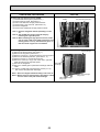
AIR TO WATER HEAT PUMP
September 2008
No. OCH439
REVISED EDITION-A
SERVICE MANUAL
R410A
[model name]
[Service Ref.]
PUHZ-W50VHA
PUHZ-W50VHA-BS
PUHZ-W85VHA
PUHZ-W85VHA-BS
PUHZ-HW112YHA
PUHZ-HW112YHA-BS
PUHZ-HW140VHA
PUHZ-HW140VHA-BS
PUHZ-HW140YHA
PUHZ-HW140YHA-BS
PUHZ-W50VHA
PUHZ-W50VHA-BS
PUHZ-W85VHA
PUHZ-W85VHA-BS
PUHZ-HW112YHA
PUHZ-HW112YHA-BS
PUHZ-HW140VHA
PUHZ-HW140VHA-BS
PUHZ-HW140YHA
PUHZ-HW140YHA-BS
Revision:
• PUHZ-W50V/HW112Y/HW140V/
HW140YHA(-BS) and PUHZW85VHA-BS are added in
REVISED EDITION-A.
• Some descriptions have been
modified.
• Please void OCH439.
Note:
• This manual describes only
service data of outdoor unit.
• RoHS compliant products have
<G> mark on the spec name plate.
CONTENTS
1. SAFETY PRECAUTION .......................................... 2
2. SPECIFICATIONS ..................................................... 5
3. DATA ............................................................................. 9
4. OUTLINES AND DIMENSIONS ..........................11
5. WIRING DIAGRAM .................................................14
6. WIRING SPECIFICATIONS ..................................18
7. REFRIGERANT SYSTEM DIAGRAM ...................19
8. TROUBLESHOOTING ...........................................21
9. DISASSEMBLY PROCEDURE ...........................58
PARTS CATALOG (OCB439)
PUHZ-W85VHA
PUHZ-W85VHA-BS
1
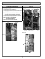
SAFETY PRECAUTION
1-1. ALWAYS OBSERVE FOR SAFETY
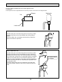
Before obtaining access to terminal, all supply circuits must be disconnected.
1-2. CAUTIONS RELATED TO NEW REFRIGERANT
Cautions for units utilizing refrigerant R410A
Do not use refrigerant other than R410A.
If other refrigerant (R22 etc.) is used, chlorine in refrigerant can cause deterioration of refrigerant oil etc.
Use a vacuum pump with a reverse flow check valve.
Vacuum pump oil may flow back into refrigerant cycle and that can cause deterioration of refrigerant oil etc.
Use the following tools specifically designed for use with R410A refrigerant.
The following tools are necessary to use R410A refrigerant.
Gauge manifold
Charge hose
Gas leak detector
Torque wrench
Tools for R410A
Vacuum pump adaptor
Electronic refrigerant
charging scale
Keep tools with care.
If dirt, dust or moisture enters into refrigerant cycle, that can cause deterioration of refrigerant oil or malfunction
of compressor.
Do not use a charging cylinder.
If a charging cylinder is used, the composition of refrigerant will change and the efficiency will be lowered.
Ventilate the room if refrigerant leaks during operation. If refrigerant comes into contact with
a flame, poisonous gases will be released.
Charge refrigerant from liquid phase of gas cylinder.
If the refrigerant is charged from gas phase, composition change may occur in refrigerant and the efficiency
will be lowered.
[1] Cautions for service
(1) Perform service after recovering the refrigerant left in unit completely.
(2) Do not release refrigerant in the air.
(3) After completing service, charge the cycle with specified amount of refrigerant.
[2] Additional refrigerant charge
When charging directly from cylinder
· Check that cylinder for R410A on the market is syphon type.
· Charging should be performed with the cylinder of syphon stood vertically. (Refrigerant is charged from liquid phase.)
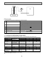
2
Unit
Gravimeter
[3] Service tools
Use the below service tools as exclusive tools for R410A refrigerant.
No.
1
Tool name
Gauge manifold
Specifications
·Only for R410A
·Use the existing fitting specifications. (UNF1/2)
·Use high-tension side pressure of 5.3 MPa·G or over.
2
Charge hose
3
Electronic scale
4
Gas leak detector
·Use the detector for R134a, R407C or R410A.
5
Adaptor for reverse flow check
·Attach on vacuum pump.
6
Refrigerant charge base
7
Refrigerant cylinder
·Only for R410A
·Use pressure performance of 5.09 MPa·G or over.
·Only for R410A
Top of cylinder (Pink)
Cylinder with syphon
8
Refrigerant recovery equipment
1-3. CAUTIONS FOR REFRIGERANT PIPING WORK
Tools for R410A (The following table shows whether conventional tools can be used or not.)
Tools and materials
Gauge manifold
Charge hose
Gas leak detector
Refrigerant recovery equipment
Refrigerant cylinder
Safety charger
Charge valve
Vacuum pump
Use
Air purge, refrigerant charge
and operation check
Gas leak check
Refrigerant recovery
Refrigerant charge
Prevent compressor malfunction
when charging refrigerant by
spraying liquid refrigerant
Prevent gas from blowing out
when detaching charge hose
Vacuum drying and air
purge
R410A tools
Tool exclusive for R410A
Tool exclusive for R410A
Tool for HFC refrigerant
Tool exclusive for R410A
Tool exclusive for R410A
Tool exclusive for R410A
Can R22 tools be used?
Can R407C tools be used?
Tool exclusive for R410A
Tools for other refrigerants can
be used if equipped with adopter for reverse flow check
Bend the pipes
Tools for other refrigerants can be used
Bender
Tools for other refrigerants can be used
Cut the pipes
Pipe cutter
Tools for other refrigerants can be used
Welder and nitrogen gas cylinder Weld the pipes
Tools for other refrigerants can be used
Refrigerant charging scale Charge refrigerant
Vacuum gauge or thermis- Check the degree of vacuum. (Vacuum Tools for other refrigerants
valve prevents back flow of oil and refri- can be used
tor vacuum gauge and
gerant to thermistor vacuum gauge)
vacuum valve
Charging cylinder
Refrigerant charge
Tool exclusive for R410A
: Prepare a new tool. (Use the new tool as the tool exclusive for R410A.)
: Tools for other refrigerants can be used under certain conditions.
: Tools for other refrigerants can be used.
3
(Usable if equipped
with adopter for reverse flow)
(Usable if equipped
with adopter for reverse flow)
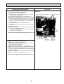
1-4. PRECAUTIONS FOR SALT PROOF TYPE "-BS" MODEL
Although "-BS" model has been designed to be resistant to salt damage, observe the following precautions to maintain the
performance of the unit.
1. Avoid installing the uint in a location where it will be exposed directly to seawater or sea breeze.
2. If the cover panel may become covered with salt, be sure to install the unit in a location where the salt will be washed away by
rainwater. (If a sunshade is installed, rainwater may not clean the panel.)
3. To ensure that water does not collect in the base of the outdoor unit, make sure that the base is level, not at angle. Water
collecting in the base of the outdoor unit could cause rust.
4. If the unit is installed in a coastal area, clean the unit with water regularly to remove any salt build-up.
5. If the unit is damaged during installation or maintenance, be sure to repair it.
6. Be sure to check the condition of the unit regularly.
7. Be sure to install the unit in a location with good drainage.
4
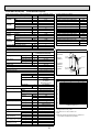
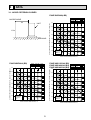
2
SPECIFICATIONS
PUHZ-W50VHA(-BS)
Power supply (Phase, Voltage, Frequency)
Nominal water flow rate (Heating mode)
Capacity
Heating
COP
(A7/W35)
Power input
Capacity
Heating
COP
(A2/W35)
Power input
Pressure difference (water circuit)
Heating pump input (based on EN14511)
Nominal water flow rate (Cooling mode)
Capacity
Cooling
EER (COP)
(A35/W7)
Power input
Capacity
Cooling
(A35/W18) EER (COP)
Power input
Pressure difference (water circuit)
Cooling pump input (based on EN14511)
1: , 230V, 50Hz
14.3
L/min
kW (Min.1.50䌾) 5.00
4.10
1.22
kW
kW (Min.1.50䌾) 5.00
3.13
1.60
kW
12
䇭kPa
0.01
kW
12.9
L/min
4.50
kW
2.94
1.53
kW
4.50
kW
4.13
1.09
kW
10
䇭kPa
0.01
kW
Nominal operating condition
Heating(A7/W35)
Outside air temperature (Dry-bulb)
Outside air temperature (Wet-bulb)
Water temperature (inlet/outlet)
Heating(A2/W35)
Outside air temperature (Dry-bulb)
Outside air temperature (Wet-bulb)
Water temperature (inlet/outlet)
Cooling(A35/W7)
Outside air temperature (Dry-bulb)
Outside air temperature (Wet-bulb)
Water temperature (inlet/outlet)
Cooling(A35/W18)
Outside air temperature (Dry-bulb)
Outside air temperature (Wet-bulb)
Water temperature (inlet/outlet)
+ 7°C
+ 6°C
+30/+35°C
+ 2°C
+ 1°C
䋭/+35°C
+35°C
+ 24°C
+12/+7°C
+35°C
+ 24°C
+23/+18°C
Note: "COP" and "Power input" in the above table are values that contains the "pump input (based on EN 14511) ".
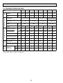
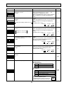
5
Plate heat exchanger
ALFA LAVAL
ACH30-30
A:40.4mm
B:268.2mm
W
Water OUT
Ref. IN
(Heating)
B
W:93mm
H:325mm
D:54mm
30 plates
H
A
Ref. OUT
(Heating)
Water IN
Thermistor
(TH32)
D
Maximum outlet water temperature
65
Maximum outlet water temptemperature [°C ]
Outdoor unit specifications
PUHZ-W50VHA(-BS)
Model name
5.4
A
Running current
Heating(A7/W35)
6.8
A
Cooling(A35/W7)
97
%
Power factor
Heating(A7/W35)
97
%
Cooling(A35/W7)
13.0
Max. current
A
16
Breaker size
A
Galvanized plate
Outer casing
Munsell 3Y 7.8/1.1
External finish
Linear expansion valve
Refrigerant control
Hermetic twin rotary
Compressor
SNB130FGCM
Model
0.9
Motor output
kW
Inverter
Start type
HP switch
Protection devices
Discharge thermo
Comp. Surface thermo
0.35 (FV50S)
Oil (Model)
L
Crankcase heater
W
Plate fin coil
Heat exchanger
Air
Plate heat exchanger
Water
Propeller fan × 1
Fan
Fan(drive)×No.
0.086
Fan motor output
kW
3
50
Air flow
m /min
(1,760)
(CFM)
*1
Defrost method
Reverse cycle
*2
Noise level (SPL)
46
Heating
dB
45 *2
Cooling
dB
950 (37-3/8)
Dimensions
Width
mm (in.)
Depth
mm (in.) 330 +30*3 (13+1-3/16)
740 (29-3/16)
Height
mm (in.)
64 (141)
Weight
kg (lbs)
R410A
Refrigerant
1.7 (3.7)
Quantity
kg (lbs)
Guaranteed operating
Heating
-15 ~ +35
°C
range (Outdoor)
Cooling
-5*4 ~ +46
°C
+60
Outlet water temp.
Heating
°C
(Max in heating, Min in cooling) Cooling
+5
°C
+5 ~ +59
Return water
Heating
°C
+8 ~ +28
°C
temperature range
Cooling
6.5 ~ 14.3
Water flow rate range
L/min
60
55
50
45
40
-20
-15
-10
-5
0
Ambient temperature [ °C ]
5
*1 Hot gas with four-way valve
*2 at distance of 1m from outdoor unit
*3 grill
*4 With the optional air outlet guide, the operation at
-15°C outdoor temperature is possible.
10
PUHZ-W85VHA(-BS)
Power supply (Phase, Voltage, Frequency)
Nominal water flow rate (Heating mode)
Capacity
Heating
COP
(A7/W35)
Power input
Capacity
Heating
COP
(A2/W35)
Power input
Pressure difference (water circuit)
Heating pump input (based on EN14511)
Nominal water flow rate (Cooling mode)
Capacity
Cooling
EER (COP)
(A35/W7)
Power input
Capacity
Cooling
(A35/W18) EER (COP)
Power input
Pressure difference (water circuit)
Cooling pump input (based on EN14511)
1㱢, 230V, 50Hz
25.8
L/min
kW (Min.2.70 䌾) 9.00
3.85
2.34
kW
kW (Min.2.60 䌾) 8.50
2.95
2.88
kW
20
䇭kPa
0.03
kW
L/min
kW
kW
kW
kW
䇭kPa
kW
21.5
7.50
2.39
3.14
7.50
3.87
1.94
15
0.02
Nominal operating condition
Heating(A7/W35)
Outside air temperature (Dry-bulb)
Outside air temperature (Wet-bulb)
Water temperature (inlet/outlet)
Heating(A2/W35)
Outside air temperature (Dry-bulb)
Outside air temperature (Wet-bulb)
Water temperature (inlet/outlet)
Cooling(A35/W7)
Outside air temperature (Dry-bulb)
Outside air temperature (Wet-bulb)
Water temperature (inlet/outlet)
Cooling(A35/W18)
Outside air temperature (Dry-bulb)
Outside air temperature (Wet-bulb)
Water temperature (inlet/outlet)
+ 7㷄
+ 6㷄
+30/+35㷄
+ 2㷄
+ 1㷄
䋭/+35㷄
+35㷄
+ 24㷄
+12/+7㷄
+35㷄
+ 24㷄
+23/+18㷄
Note: "COP" and "Power input" in the above table are values that contains the "pump input (based on EN 14511) ".
Oil (Model)
Crankcase heater
Heat exchanger
Fan
Air
Water
Fan(drive)×No.
Fan motor output
Air flow
Defrost method
Noise level (SPL)
L
W
kW
m3/min
(CFM)
Heating
Cooling
Width
Depth
Height
dB
dB
mm (in.)
mm (in.)
mm (in.)
kg (lbs)
Quantity
Guaranteed operating
Heating
range (Outdoor)
Cooling
Outlet water temp.
Heating
(Max in heating, Min in cooling) Cooling
Return water
Heating
temperature range
Cooling
Water flow rate range
kg (lbs)
㷄
㷄
㷄
㷄
㷄
㷄
L/min
Dimensions
Weight
Refrigerant
0.67 (FV50S)
Plate fin coil
Plate heat exchanger
Propeller fan × 1
0.060
55
(1,940)
Reverse cycle
48 *2
*2
48
950 (37-3/8)
*3
*1
330 +30 (13+1-3/16)
943 (37-1/8)
77 (170)
R410A
2.4 (5.3)
-20 䌾 +35
*4
-5 䌾 +46
+60
+5
+5 䌾 +59
+8 䌾 +28
10.0 䌾 25.8
6
Plate heat exchanger
ALFA LAVAL
ACH30-40
A:40.4mm
B:268.2mm
W
Water OUT
Ref. IN
(Heating)
B
W:93mm
H:325mm
D:69mm
40 plates
H
A
Ref. OUT
(Heating)
Water IN
Thermistor
(TH32)
D
Maximum outlet water temperature
65
Maximum outlet water temptemperature [㷄]
Outdoor unit specifications
PUHZ-W85VHA(-BS)
Model name
10.3
A
Running current
Heating(A7/W35)
13.7
A
Cooling(A35/W7)
98
%
Power factor
Heating(A7/W35)
98
%
Cooling(A35/W7)
23.0
Max. current
A
25
Breaker size
A
Galvanized plate
Outer casing
Munsell 3Y 7.8/1.1
External finish
Linear expansion valve
Refrigerant control
Hermetic twin rotary
Compressor
TNB220FLHM1
Model
1.3
Motor output
kW
Inverter
Start type
HP switch
Protection devices
Discharge thermo
60
55
50
45
40
-20
-15
-10
-5
0
Ambient temperature [㷄]
5
*1 Hot gas with four-way valve
*2 at distance of 1m from outdoor unit
*3 grill
*4 With the optional air outlet guide, the operation at
-15㷄 outdoor temperature is possible.
10
PUHZ-HW112YHA(-BS)
Power supply (Phase, Voltage, Frequency)
Nominal water flow rate (Heating mode)
Capacity
Heating
COP
(A7/W35)
Power input
Capacity
Heating
COP
(A2/W35)
Power input
Pressure difference (water circuit)
Heating pump input (based on EN14511)
Nominal water flow rate (Cooling mode)
Capacity
Cooling
EER (COP)
(A35/W7)
Power input
Capacity
Cooling
(A35/W18) EER (COP)
Power input
Pressure difference (water circuit)
Cooling pump input (based on EN14511)
3㱢, 400V, 50Hz
L/min
32.1
kW (Min. 3.40 䌾) 11.20
4.24
2.64
kW
kW (Min. 3.40 䌾) 11.20
3.01
3.72
kW
6
䇭kPa
0.01
kW
L/min
kW
kW
kW
kW
䇭kPa
kW
28.7
10.00
2.72
3.68
10.00
4.07
2.46
5
0.01
Nominal operating condition
Heating(A7/W35)
Outside air temperature (Dry-bulb)
Outside air temperature (Wet-bulb)
Water temperature (inlet/outlet)
Heating(A2/W35)
Outside air temperature (Dry-bulb)
Outside air temperature (Wet-bulb)
Water temperature (inlet/outlet)
Cooling(A35/W7)
Outside air temperature (Dry-bulb)
Outside air temperature (Wet-bulb)
Water temperature (inlet/outlet)
Cooling(A35/W18)
Outside air temperature (Dry-bulb)
Outside air temperature (Wet-bulb)
Water temperature (inlet/outlet)
+ 7㷄
+ 6㷄
+30/+35㷄
+ 2㷄
+ 1㷄
䋭/+35㷄
+35㷄
+ 2 4㷄
+12/+7㷄
+35㷄
+ 24㷄
+23/+18㷄
Note: "COP" and "Power input" in the above table are values that contains the "pump input (based on EN 14511) ".
7
Plate heat exchanger
ALFA LAVAL
ACH50-50
W
Water OUT
Ref. IN
(Heating)
A:50mm
B:466mm
B
W:112mm
H:526mm
D:130mm
50 plates
H
A
Ref. OUT
(Heating)
Water IN
Thermistor
(TH32)
D
Maximum outlet water temperature
65
Maximum outlet water temptemperature [㷄]
Outdoor unit specifications
PUHZ-HW112YHA(-BS)
Model name
4.0
A
Running current
Heating(A7/W35)
5.6
A
Cooling(A35/W7)
95
%
Power factor
Heating(A7/W35)
95
%
Cooling(A35/W7)
13.0
Max. current
A
16
Breaker size
A
Galvanized plate
Outer casing
Munsell 3Y 7.8/1.1
External finish
Linear expansion valve
Refrigerant control
Hermetic scroll
Compressor
ANB33FJFMT
Model
2.5
Motor output
kW
Inverter
Start type
HP switch
Protection devices
LP switch
Discharge thermo
0.9 (FV50S)
Oil (Model)
L
Crankcase heater
W
Plate fin coil
Heat exchanger
Air
Plate heat exchanger
Water
Propeller fan × 2
Fan
Fan(drive)×No.
0.074 x 2
Fan motor output
kW
3
100
Air flow
m /min
(3,530)
(CFM)
*1
Defrost method
Reverse cycle
*2
Noise level (SPL)
Heating
dB
53
*2
Cooling
dB
53
1020 (40-3/16)
Dimensions
Width
mm (in.)
Depth
mm (in.) 330 +30*3 (13+1-3/16)
1350 (53-1/8)
Height
mm (in.)
148 (326)
Weight
kg (lbs)
R410A
Refrigerant
4.0 (8.8)
Quantity
kg (lbs)
Guaranteed operating
Heating
-25 䌾 +35
㷄
*4
range (Outdoor)
Cooling
㷄
-5 䌾 +46
+60
Outlet water temp.
Heating
㷄
(Max in heating, Min in cooling) Cooling
+5
㷄
+5 䌾 +59
Return water
Heating
㷄
+8 䌾 +28
temperature range
Cooling
㷄
14.4 䌾 32.1
Water flow rate range
L/min
60
55
50
45
40
-25
-20
-15
-10
-5
0
Ambient temperature [㷄]
5
*1 Hot gas with four-way valve
*2 at distance of 1m from outdoor unit
*3 grill
*4 With the optional air outlet guide, the operation at
-15㷄 outdoor temperature is possible.
10
PUHZ-HW140VHA(-BS)
PUHZ-HW140YHA(-BS)
Power supply (Phase, Voltage, Frequency)
Nominal water flow rate (Heating mode)
Capacity
Heating
COP
(A7/W35)
Power input
Capacity
Heating
COP
(A2/W35)
Power input
Pressure difference (water circuit)
Heating pump input (based on EN14511)
Nominal water flow rate (Cooling mode)
Capacity
Cooling
EER (COP)
(A35/W7)
Power input
Capacity
Cooling
EER (COP)
(A35/W18)
Power input
Pressure difference (water circuit)
Cooling pump input (based on EN14511)
1/3㱢, 230/400V, 50Hz
L/min
kW
kW
kW
kW
䇭kPa
kW
L/min
kW
kW
kW
kW
䇭kPa
kW
40.1
(Min. 4.20 䌾 ) 14.00
4.19
3.34
(Min. 4.20 䌾 ) 14.00
2.69
5.21
9
0.02
35.8
12.50
2.59
4.82
12.50
4.01
3.12
7
0.02
Nominal operating condition
Heating(A7/W35)
Outside air temperature (Dry-bulb)
Outside air temperature (Wet-bulb)
Water temperature (inlet/outlet)
Heating(A2/W35)
Outside air temperature (Dry-bulb)
Outside air temperature (Wet-bulb)
Water temperature (inlet/outlet)
Cooling(A35/W7)
Outside air temperature (Dry-bulb)
Outside air temperature (Wet-bulb)
Water temperature (inlet/outlet)
Cooling(A35/W18)
Outside air temperature (Dry-bulb)
Outside air temperature (Wet-bulb)
Water temperature (inlet/outlet)
+ 7㷄
+ 6㷄
+30/+35㷄
+ 2㷄
+ 1㷄
䋭/+35㷄
+35㷄
+ 24㷄
+12/+7㷄
+35㷄
+ 24㷄
+23/+18㷄
Note: "COP" and "Power input" in the above table are values that contains the "pump input (based on EN 14511) ".
Running current
Power factor
Heating(A7/W35)
Cooling(A35/W7)
Heating(A7/W35)
Cooling(A35/W7)
Max. current
Breaker size
Outer casing
External finish
Refrigerant control
Compressor
PUHZ-HW140VHA(-BS) /
PUHZ-HW140YHA(-BS)
14.9 / 5.1
A
21.5 / 7.3
A
97 / 95
%
97 / 95
%
35.0 / 13.0
A
40 / 16
A
Galvanized plate
Munsell 3Y 7.8/1.1
Linear expansion valve
Hermetic scroll
Model
Motor output
kW
Start type
Protection devices
Oil (Model)
Crankcase heater
Heat exchanger
Fan
Air
Water
Fan(drive)×No.
Fan motor output
Air flow
Defrost method
Noise level (SPL)
Dimensions
Heating
Cooling
Width
Depth
Height
Weight
Refrigerant
Quantity
Heating
Cooling
Heating
(Max in heating, Min in cooling) Cooling
Return water
Heating
temperature range
Cooling
Water flow rate range
Guaranteed operating
range (Outdoor)
Outlet water temp.
ANB33FJGMT/ANB33FJFMT
2.5
Inverter
HP switch
LP switch
Discharge thermo
0.9 (FV50S)
L
W
Plate fin coil
Plate heat exchanger
Propeller fan × 2
0.074 x 2
kW
100
m3/min
(3,530)
(CFM)
Reverse cycle *1
dB
53 *2
dB
53 *2
1020 (40-3/16)
mm (in.)
mm (in.)
330 +30*3 (13+1-3/16)
1350 (53-1/8)
mm (in.)
134 (296) / 148 (326)
kg (lbs)
R410A
4.0 (8.8)
kg (lbs)
-25 䌾 +35
㷄
㷄
-5*4 䌾 +46
+60
㷄
+5
㷄
+5 䌾 +59
㷄
+8 䌾 +28
㷄
17.9 䌾 40.1
L/min
8
Plate heat exchanger
ALFA LAVAL
ACH50-50
W
Water OUT
Ref. IN
(Heating)
A:50mm
B:466mm
B
W:112mm
H:526mm
D:130mm
50 plates
H
A
Ref. OUT
(Heating)
Water IN
Thermistor
(TH32)
D
Maximum outlet water temperature
65
Maximum outlet water temptemperature [㷄]
Outdoor unit specifications
Model name
60
55
50
45
40
-25
-20
-15
-10
-5
0
Ambient temperature [㷄]
5
*1 Hot gas with four-way valve
*2 at distance of 1m from outdoor unit
*3 grill
*4 With the optional air outlet guide, the operation at
-15㷄 outdoor temperature is possible.
10
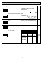
3
DATA
3-1. NOISE CRITERION CURVES
PUHZ-W50VHA(-BS)
MODE SPL(dB)
COOLING
45
HEATING
46
MICROPHONE
90
UNIT
1.5m
GROUND
PUHZ-W85VHA(-BS)
MODE SPL(dB)
COOLING
48
HEATING
48
OCTAVE BAND SOUND PRESSURE LEVEL, dB (0 dB = 0.0002 bar)
OCTAVE BAND SOUND PRESSURE LEVEL, dB (0 dB = 0.0002 bar)
70
NC-70
60
NC-60
50
NC-50
40
NC-40
30
NC-30
20
10
APPROXIMATE
THRESHOLD OF
HEARING FOR
CONTINUOUS
NOISE
63
NC-20
125
250
500 1000 2000 4000
BAND CENTER FREQUENCIES, Hz
MODE SPL(dB)
COOLING
53
HEATING
53
8000
LINE
90
80
70
NC-70
60
NC-60
50
NC-50
40
NC-40
30
NC-30
10
80
PUHZ-HW112YHA(-BS)
PUHZ-HW140VHA(-BS)
PUHZ-HW140YHA(-BS)
LINE
90
20
OCTAVE BAND SOUND PRESSURE LEVEL, dB (0 dB = 0.0002 bar)
1m
LINE
APPROXIMATE
THRESHOLD OF
HEARING FOR
CONTINUOUS
NOISE
63
125
250
500 1000 2000 4000
BAND CENTER FREQUENCIES, Hz
NC-20
8000
9
80
70
NC-70
60
NC-60
50
NC-50
40
NC-40
30
NC-30
20
10
APPROXIMATE
THRESHOLD OF
HEARING FOR
CONTINUOUS
NOISE
63
125
250
500 1000 2000 4000
BAND CENTER FREQUENCIES, Hz
NC-20
8000
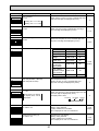
3-2. STANDARD OPERATION DATA
Cooling Heating Cooling Heating Cooling Heating Cooling Heating
(A35/W7) (A7/W35) (A35/W7) (A7/W35) (A35/W7) (A7/W35) (A35/W7) (A7/W35)
Outdoor
Water
conditions conditions
Refrigerant circuit
Electrical circuit
Total
Mode
Capacity
W
4,500
5,000
7,500
9,000
10,000
11,200
12,500
14,000
Input
kW
1.52
1.21
3.12
2.31
3.67
2.63
4.80
3.32
Outdoor unit
PUHZ-W50VHA
Phase, Hz
PUHZ-W85VHA PUHZ-HW112YHA
PUHZ-HW140VHA
/ PUHZ-HW140YHA
1, 50
1, 50
3, 50
1 / 3, 50
230
230
400
230 / 400
Voltage
V
Current
A
6.8
5.4
13.7
10.3
5.6
4.0
Discharge pressure
MPa
2.51
2.13
2.81
2.21
2.63
2.07
2.81
2.11
Suction pressure
MPa
0.83
0.68
0.73
0.64
0.78
0.69
0.78
0.66
Discharge temperature
ºC
69
68
80
65
78
64
84
67
Condensing temperature
ºC
43
37
46
38
46
36
47
37
Suction temperature
ºC
6
6
3
-1
9
5
11
3
L/min
12.9
14.3
20.4
25.8
28.7
32.1
35.8
40.1
Outlet water temperature
ºC
7
35
7
35
7
35
7
35
D.B.
ºC
35
7
35
7
35
7
35
7
W.B. ºC
24
6
24
6
24
6
24
6
Flow volume
Intake air
temperature
The unit of pressure has been changed to MPa based on international SI system.
The conversion factor is: 1 (MPa) = 10.2 (kgf/cm2)
10
21.5 / 7.314.9 / 5.1
Water IN
Air Intake
Water OUT
Handle for moving
m
0m
50
er
Ov
m
0m
r1
Ov
e
50
er
Ov
mm
10
mm
00
r3
e
Ov
Service space
Over10
Over
Over300
Handle for moving
Less than
Side Air Intake
Handle for moving
Rear Air Intake
500
Over
500
FREE
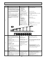
3 FOUNDATION BOLTS
FOUNDATION
<Foundation bolt height>
Handle for moving
Side Air Intake
Please secure the unit firmly
with 4 foundation (M10) bolts.
(Bolts and washers must be
purchased locally.)
30
2 SERVICE SPACE
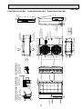
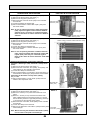
Dimensions of space needed
for service access are
shown in the below diagram.
23
30
322
220
175
145
145
Earth terminal
950
145
Air Discharge
Installation Feet
600
Rear Air Intake
Service panel
Handle for moving
Power supply
wiring hole
(2-:27Knock Out)
Terminal Connections
Left•••• Power supply wiring
Right •• Controller wiring
2-12 x 36 oval holes
(Foundation Bolt M10)
Drain hole
(5-:33)
175
2-U Shaped notched holes
(Foundfation Bolt M10)
417
1 FREE SPACE (Around the unit)
53
469
330
30
371
19
370
28
The diagram below shows a
basic example.
Explantion of particular details are
given in the installation manuals etc.
740
219
81
40
11
119
34
Front cover
see Detail
Detail
24
ISO 228/1-G1 B
269
85
4
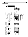
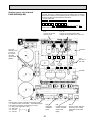
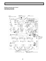
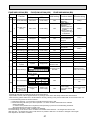
OUTLINES AND DIMENSIONS
PUHZ-W50VHA(-BS)
Unit: mm
r
e
Ov
0
50
m
0m
r1
Ov
e
FREE
Water IN
Air Intake
Water OUT
Handle for moving
mm
er
Ov
10
mm
mm
00
r3
e
Ov
Over10
57
Service space
500
Over
Dimensions of space needed
for service access are
shown in the below diagram.
Over300
Rear Air Intake
500
Over
The diagram below shows a
basic example.
Explantion of particular details are
given in the installation manuals etc.
Less than
Handle for moving
Handle for moving
Side Air Intake
FOUNDATION
<Foundation bolt height>
Please secure the unit firmly
with 4 foundation (M10) bolts.
(Bolts and washers must be
purchased locally.)
30
Handle for moving
Side Air Intake
23
30
322
220
175
145
145
Earth terminal
950
145
Air Discharge
Installation Feet
600
Rear Air Intake
Service panel
Power supply wiring hole
(2-:27 knockout)
Handle for moving
Terminal Connections
Left...Power supply wiring
Right...Controller wiring
2-12 x 36 oval holes
(Foundation Bolt M10)
Drain hole
(5-:33)
175
2-U Shaped notched holes
(Foundfation Bolt M10)
19
370
28
3 FOUNDATION BOLTS
330
30
473
417
2 SERVICE SPACE
943
219
12
81
53
673
119 40
34
Rear cover
Front cover
See Detail
Detail
24
ISO 228/1-G1 B
269
98
1 FREE SPACE (Around the unit)
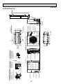
Unit: mm
PUHZ-W85VHA(-BS)
er
Ov
Water IN
Water OUT
m
0m
50
m
0m
er
1
Handle for moving
Ov
59
Ov
10
mm
0
30
er
er
Ov
mm
Over10
Service space
500
Handle for moving
Side Air Intake
Over300
Handle for moving
Rear Air Intake
500
Over
Over
FREE
3 FOUNDATION BOLTS
FOUNDATION
<Foundation bolt height>
Handle for moving
Handle for moving
Side Air Intake
1350
Please secure the unit firmly
with 4 foundation (M10) bolts.
(Bolts and washers must be
purchased locally.)
30
256
322
210
600
133
133
Earth terminal
1020
133
Air Discharge
Installation Feet
Rear Air Intake
Drain hole
(5-:33)
1079
931
YHA
A
Power supply
wiring hole
(2-:27Knock Out)
VHA
Handle for moving
Service panel
Terminal connections
Left•••••Power supply wiring
Right •••Controller wiring
2-12×36 oval holes
(Foundation Bolt M10)
210
2-U Shaped notched holes
(Foundfation Bolt M10)
19
370
2 SERVICE SPACE
53
28
Dimensions of space needed
for service access are
shown in the below diagram.
330
30
23
417
1 FREE SPACE (Around the unit)
635
371
219
81
13
A
34
Detail
Front cover
24
Air Intake
see Detail
ISO 228-1
G1 B
PUHZ-HW140VHA(-BS)
40
PUHZ-HW112YHA(-BS)
74
466
74
The diagram below shows a
basic example.
Explantion of particular details are
given in the installation manuals etc.
Unit: mm
PUHZ-HW140YHA(-BS)
Less than
5
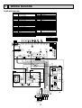
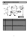
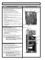
WIRING DIAGRAM
PUHZ-W50VHA(-BS)
SYMBOL
TB1
NAME
Terminal Block<Power Supply,Interface unit /
Flow temp. controller>
MC
MF1
21S4
SV
63H
63HS
TH3
TH4
TH6
TH7
TH8
TH32
TH33
LEV-A, LEV-B
ACL
CY1,CY2
P.B.
R/S
U/V/W
Motor for Compressor
Fan Motor
Solenoid Valve<Four-Way Valve>
Solenoid Valve<Bypass Valve>
High Pressure Switch
High Pressure Sensor
Thermistor<Liquid>
Thermistor<Discharge>
Thermistor<Plate HEX Iiquid>
Thermistor<Ambient>
Thermistor<Heatsink>
Thermistor<Inlet water>
Thermistor<Comp Surface>
Electronic Expansion Valve
Reactor
Capacitor
Power Circuit Board
Connection Terminal<L/N-Phase>
Connection Terminal<U/V/W-Phase>
SYMBOL
CB1-3
PFC/IPM
N.F.
LI,LO
NI,NO
EI,E2,E3
52C
C.B.
SW1
SW2
SW5
SW6
SW8
SW10
SV1
CNDM
NAME
Main Smocthing Capacitor
Power Module
Noise Filter Circuit Board
Connection Terminal<L-Phase>
Connection Terminal<N-Phase>
Connection Terminal<Ground>
52C Relay
Controller Circuit Board
Switch<Function Switch>
Switch<Function Switch>
Switch<Function Switch>
Switch<Model Select>
Switch<Function Switch>
Switch<Model Select>
Connector<Connection for Option>
Connector
<Connection for Option (Contact Input)>
LED3
LED<Operation/Inspection Indicators>
F1~ F4
Fuse<T6.3AL250V>
X52,X54, X55 Relay
*1 MODEL SELECT
SW6
TH33 TH32 TH7 TH6 TH3 TH4
C. B.
t°
t°
t°
t°
M
M
1
0
2 3
0 1
SW10
4
1
5
0
1=ON, 0=OFF
1
TH7/6 TH3 TH4
(RED) (WHT) (WHT)
3 1
63HS
(WHT)
LEV-A
(WHT)
6 1
61
3 1
LEV-B CNVMNTCNMNT
(RED)
(WHT) (WHT)
5
SW2
4 1 2 1 2
2 1
3
TRANS
1
CN2
(WHT)
1
CNDC
(PNK)
CN52C
(RED)
CN4
(WHT)
1 2
1 2
7
CN51 CNDM CN3S
(WHT) (WHT) (WHT)
3
LED3
2
2
2
3
4
F4
21S4 3
(GRN)
X54
1
X55
1 3
1 SV2 3
(BLU)
1 SV1
(GRY)
21S4
RED
RED
WHT
WHT
WHT
N. F.
NO
LO
2
52C
1
CN52C
(BLK)
2
RED
2
E3
CN4 1
(WHT) 2
BLK
1
3
TH8
CN3 1
(WHT) 2
CN5
(RED)
TABU
TABV
TABW
2
1
t°
5
1
2
2
BLK
E2
IPM
CN5 1
(RED) 2
CNAC2
(RED)
BLK
PFC
TABR
RED
WHT
TABS
5
RED
MS MC
3~
U
V
WHT
P. B.
3
1
SV
ACL
W
1
3
1
CN2
(WHT)
CB3
1
7
L
GRN/YLW
N
CNAC1
(WHT)
BRN
ORN
YLW
3
BLU
CB2
RED
CB1
CY1
CY2
S1 S2 S3 TB1
Interface unit /
Flow temp. controller
POWER SUPPLY
~ / N 230V 50Hz
14
U
U
LI
EI
NI
BLK
F1
1
F3
CNAC
(WHT)
X52
5
*1
SW10
2 1
63H
(YLW)
3
2
1
t°
1
CNS
(WHT)
1
0
*1
1
TH33 TH32
(YLW) (BLK)
F2
6
0
SW6
CNF1
(WHT)
LEV-B
SW8 SW5
7
LEV-A
SW1
MF1
MS
3~
t°
1
63HS
63H
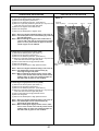
PUHZ-W85VHA(-BS)
SYMBOL
TB1
NAME
Terminal Block <Power Supply,Interface unit /
Flow temp. controller>
MC
MF1
21S4
SV
63H
63HS
TH3
TH4
TH6
TH7
TH8
TH32
LEV-A, LEV-B
DCL
ACTM
CY1,CY2
P.B.
TABU/V/W
TABS/T
TABP1/P2
Motor for Compressor
Fan Motor
Solenoid Valve <Four-Way Valve>
Solenoid Valve <Bypass Valve>
High Pressure Switch
High Pressure Sensor
Thermistor <Liquid>
Thermistor <Discharge>
Thermistor <Plate HEX Liquid>
Thermistor <Ambient>
Thermistor <Heatsink>
Thermistor <Inlet water>
Electronic Expansion Valve
Reactor
Active Filter Module
Capacitor
Power Circuit Board
Connection Terminal <U/V/W-Phase>
Connection Terminal <L/N-Phase>
Connection Terminal <DC Voltage>
SYMBOL
TABN1/N2
DS2, DS3
IPM
N.F.
LI,LO
NI,NO
EI,E2
52C
C.B.
SW1
SW2
SW5
SW6
SW8
SW10
SV1
CNDM
NAME
Connection Terminal <DC Voltage>
Diode bridge
Power Module
Noise Filter Circuit Board
Connection Terminal <L-Phase>
Connection Terminal <N-Phase>
Connection Terminal <Ground>
52C Relay
Controller Circuit Board
Switch <Function Switch>
Switch <Function Switch>
Switch <Function Switch>
Switch <Model Select>
Switch <Function Switch>
Switch <Model Select>
Connector <Connection for Option>
Connector
<Connection for Option(Contact Input)>
LED3
LED <Operation/ Inspection Indicators>
F1~ F4
Fuse <T6.3AL250V>
X52,X54, X55 Relay
*1 MODEL SELECT
SW 6
TH32 TH7 TH6 TH3 TH4
M
M
4
0
3 1
1
TH7/6 TH3 TH4
(RED) (WHT) (WHT)
6 1
LEV-A
(WHT)
63HS
(WHT)
61
3 1
LEV-B CNVMNTCNMNT
(RED)
(WHT) (WHT)
5
1
63H
(YLW)
3
TRANS
1
CNDM1
(WHT)
2
4
21S4 3
(GRN)
X54
3
F4
X55
1
2
X52
F1
3
F3
CNAC
(WHT)
1
1 3
1 SV2 3
(BLU)
1 SV1
(GRY)
3
1
CN51
(WHT)
5
SV
BLU
WHT
21S4
1
3
LED3
2
F2
2
0
*1
CN3S
(WHT)
1 2
1 2
7
7
CNS
(WHT)
1
0
*1
CN52C
(RED)
CN4
(WHT)
CN2
(WHT)
1
CNDC
(PNK)
6
0
1=ON, 0=OFF
3
2
SW10
5
1
t°
4 1 2 1 2
2 1
TH32
(BLK)
t°
2 3
0 1
SW10 SW2
1
t°
1
0
SW6
CNF1
(WHT)
t°
LEV-B
SW1
7
N. F.
NO
LO
52C
CN52C
(BLK)
2
2
1
E2
CN5
(RED)
2
CNAC1
(WHT)
1
U
RED
L2
BLK
1
P
N1
N2
6
L
N
BLU
BRN
ORN
GRN/YLW
RED
WHT
L1
BLU
YLW
W
MS MC
3~
4
EI
NI U
RED
WHT
TABW
BLK
LI
V
DCL
2
1
3
U
TABN2
TABN1
U
BLK
TABP1 RED
TABV
TABN
TABP
TABS WHT
BLK
7
1 CN3
2(WHT)
1 CN5
2 (RED)
1 CN4
2(WHT)
RED TABU
2
DS2
3
1
WHT
BLK
2
TABT BLU
IPM
WHT
TH8
DS3
3
6
1
CN2
(WHT)
t°
CNDC
(PNK)
CNAC2
(RED)
1
CNAF
(WHT)
7
2
1
P. B.
4
TABP2
RED
MF1
MS
3~
t°
1
LEV-A
SW8 SW5
C. B.
63HS
63H
CY1
CY2
S1 S2 S3
TB1
RED
WHT
Io
Interface unit /
Flow temp. controller
ACTM
POWER SUPPLY
~ / N 230V 50Hz
15
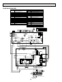
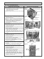
PUHZ-HW140VHA(-BS)
P.B.
NAME
U/V/W
Terminal Block<Power Supply, Interface unit /
Flow Temp. controller-Outdoor>
LI
Motor for Compressor
MC
NI
Fan Motor
MF1,MF2
DCL1,DCL2
21S4
Solenoid Valve<Four-Way Valve>
IGBT
High Pressure Switch
63H
EI,E2,E3,E4
63L
Low Pressure Switch
C.B.
High Pressure Sensor
63HS
SW1
TH3
Thermistor<Liquid>
TH4
Thermistor<Discharge>
SW2
TH6
Thermistor<Plate HEX Liquid>
SW5
TH7
Thermistor<Ambient>
SW6
TH32
Thermistor<Return Water>
SW8
TH33
Thermistor<Suction>
CN31
LEV-A, LEV-B, LEV-C Electronic Expansion Valve
SS
DCL
Reactor
SV1
CB
Main Smoothing Capacitor
CNDM
CY1,CY2
Capacitor
LED3
F1,F2,F3,F4
X51,X52, X54
SYMBOL
TB1
Power Circuit Board
Connection Terminal<U/V/W-Phase>
Connection Terminal<L-Phase>
Connection Terminal<N-Phase>
Connection Terminal<Reactor>
Power Module
Connection Terminal<Ground>
Controller Circuit Board
Switch<Manual Defrost, Defect History
Record Reset, Function Switch>
Switch<Function Switch>
Switch<Function Switch,Model Select>
Switch<Model Select>
Switch<Function Switch>
Connector<Emergency Operation>
Connector<Connection for Option>
Connector<Connection for Option>
Connector
<Connection for Option(Contact Input)>
LED<Operation/Inspection Indicators>
Fuse<T6.3AL250V>
Relay
1MODEL SELECT
*MODEL
SW6
LEV-C
M
t°
TH33 TH32 TH7/6 TH3 TH4
(YLW) (BLK) (RED) (WHT) (WHT)
1
1
3
CNF2
(WHT)
7
3 1
1
6 1
6 1 3 1
3 63HS
LEV-A
LEV-B CNVMNTCNMNT
63L
(RED)
(WHT)
CN52C
(RED)
1
1 2
7
1 LEV-C 6
2
1
F1
1
1
2
3
4
F3
21S4 3
(GRN)
F4
1
1 SV1
(GRY)
3
5
1 SS
(WHT)
3
21S4
2
P. B.
1
2
CN4
(WHT)
1
CN2
(WHT)
CN52C
3 (RED)
1
7
52C
52C
BLK
2
N2
3
1
1
P2
RED
CNAC2
(RED)
WHT
E3
CNDC
(PNK)
CB
IGBT
3
E2
BLK
1
CNAC1
(WHT)
3
E4
W V U
MS
3~
DCL2
DCL1
EI
DCL
RED
MC
L
NI U
U
LI
BLK
BLK
N
S1
CY1
CY2
S2
BRN
RED
W V U
BLK
WHT
3
7
CNAC
(WHT)
1
LED3
3
1
X52
F2
CN31
3
3
(BLU)
CNDC
(PNK)
CNS
(WHT)
(WHT) (WHT)
X51
1
TRANS
2
CN2
(WHT)
(RED)
5
CN4
(WHT)
63H
(YLW)
3
(WHT)
1 2 3 4 5 6
SW2
t°
4 1 2 2 1
SW6
t°
*2
CN51 CNDM
(WHT) (WHT)
t°
2 1
1 2 3 4 5 6 7 8
ORN
1
t°
31
GRN/YLW
YLW
MF2
MS
3~
t°
CNF1
7 (WHT) 1
SW5-6
ON
OFF
*2. SW5 -1 to 5 : Function Switch
*1 * 1
5
X54
1
LEV-B
M
BLU
MF1
MS
3~
LEV-A
M
ON
140V OFF
SW8 SW5
TH33TH32TH7 TH6 TH3 TH4
C. B.
63HS
SW1
63H 63L
S3 TB1
Interface unit /
Flow Temp. controller
POWER SUPPLY
~/N 230V 50Hz
16
RED
WHT
PUHZ-HW112YHA(-BS) PUHZ-HW140YHA(-BS)
SYMBOL
TB1
TB2
NAME
Terminal Block<Power Supply>
Terminal Block<Interface unit /Flow Temp.
controller-Outdoor>
MC
MF1,MF2
21S4
63H
63L
63HS
TH3
TH4
TH6
TH7
TH32
TH33
LEV-A, LEV-B, LEV-C
ACL1/2/3/4
RS
CB1,CB2
CK
P.B.
TB-U/V/W
TB-L1/L2/L3
TB-P2
TB-C1
TB-N1
X52A
Motor for Compressor
Fan Motor
Solenoid Valve<Four-Way Valve>
High Pressure Switch
Low Pressure Switch
High Pressure Sensor
Thermistor<Liquid>
Thermistor<Discharge>
Thermistor<Plate HEX Liquid>
Thermistor<Ambient>
Thermistor<Inlet Water>
Thermistor<Suction>
Electronic Expansion Valve
Reactor
Rush Current Protect Resistor
Main Smoothing Capacitor
Capacitor
Power Circuit Board
Connection Terminal<U/V/W-Phase>
Connection Terminal<L1/L2/L3-Power Supply>
Connection Terminal
Connection Terminal
Connection Terminal
52C Relay
SYMBOL
N.F.
LI1/LI2/LI3/NI
LO1/LO2/LO3/NO
GD1,GD3
CONV.B.
L1-A1/IN
L1-A2/OU
L2-A2/OU
L3-A2/OU
N-IN
CK-OU
C.B.
SW1
NAME
Noise Filter Circuit Board
Connection Terminal<L1/L2/L3/N-Power Supply>
Connection Terminal<L1/L2/L3/N-Power Supply>
Connection Terminal<Ground>
Converter Circuit Board
Connection Terminal<L1-Power Supply>
Connection Terminal<L1-Power Supply>
Connection Terminal<L2-Power Supply>
Connection Terminal<L3-Power Supply>
Connection Terminal<N-Power Supply>
Connection Terminal
Controller Circuit Board
Switch<Manual Defrost, Defect History
Record Reset, Function Switch>
SW2
Switch<Function Switch>
SW5
Switch<Function Switch,Model Select>
SW6
Switch<Model Select>
SW8
Switch<Function Switch>
CN31
Connector<Emergency Operation>
Connector<Connection for Option>
SS
Connector<Connection for Option>
SV1
Connector
CNDM
<Connection for Option (Contact Input)>
LED3
LED<Operation/Inspection Indicators>
F1,F2,F3,F4 Fuse<T6.3AL250V>
X51,X52, X54 Relay
*1MODEL SELECT
MODEL
M
TH33 TH32 TH7 TH6 TH3 TH4
C. B.
t°
1
3
7
3 1
5
1
6 1
6 1 3 1
3 63HS
LEV-A
LEV-B CNVMNTCNMNT
63L
(RED)
1
TRANS
CN2
(WHT)
7
1 LEV-C 6
2
F1
1
1
2
3
4
1
LED3
(BLU)
3
1
X52
7
F3
CNAC
(WHT)
(WHT) (WHT)
CN31
CNDC
(PNK)
F2
1 2 3 4 5 6
1 2
1
3
(RED)
5
CN4
(WHT)
63H
(YLW)
3
(WHT)
(WHT)
1 2 3 4 5 6
*1
SW6
1
SW1
4 1 2 2 1
2 1
CNF2
(WHT)
CNS
(WHT)
1 2 3 4 5 6 7 8
*1
31
TH33 TH32 TH7/6 TH3 TH4
(YLW) (BLK) (RED) (WHT) (WHT)
ON
OFF
*2. SW5 -1 to 5 : Function Switch
t°
CNF1
7 (WHT) 1
2
1 2 3 4 5 6 7 8
CN51 CNDM
(WHT) (WHT)
1
t°
SW8 SW5
MF2
MS
3~
t°
ON
140Y OFF
LEV-B
M
21S4 3
(GRN)
F4
1
X51
1
t°
LEV-A
M
X54
MF1
MS
3~
t°
63HS
SW5-6 *2
ON
OFF
SW2
63H 63L
SW6
ON
112Y OFF
LEV-C
1 SV1
(GRY)
3
5
1 SS
(WHT)
3
21S4
3
7
1
3 1
CN7
(WHT)
-
TB-U
TB-L3
TB-L2
TB-L1
+
-
X52A
RED
RS
BLK
LI3
BLU NI
L1-IN
L1-A1
CNAC2
3 (RED)
U
LO2 WHT
U
LO3 BLK
U
NO
GD3
GD1
17
CNDC 1
(PNK)
2
3 3
BLU
+
+
U
BRN
N
LI2 U
21
ACL1
LO1 RED
BLK
L3
WHT
CNCT
(RED) 1
3
BLK
L2
RED
GRN/YLW
L1
LI1
CONV.B.
RED
CNAC1
(WHT)1
TB1
RED
2
N.F.
POWER
SUPPLY
3N~
400V 50Hz
3
1
L1-OU RED
L1-A2
3
CK
N-IN
+
CB2
BLK CK-OU
BLK
+
CB1
U -1 CNL
(BLU)
WHT
S3
TB-N1
TB-C1
WHT
S2
+
TB-P2
RED
Interface
unit /
Flow temp.
controller
YLW
S1
BLK
WHT
RED
+
RED
BRN
ORN
TB2
BLK W MC
WHT V MS
RED U 3~
TB-V
L2-OU WHT
L2-A2 RED
2
TB-W
+
2 CN4
1(WHT)
2 CN5
1(RED)
BLK
L3-OU BLK
CN7
(WHT) L3-A2
WHT
2
CN2 7
(WHT)
BLU
P.B.
ACL4
ACL2
ACL3
6
WIRING SPECIFICATIONS
FIELD ELECTRICAL WIRING (power wiring specifications)
Circuit rating
Wiring
Wire No. ×
size (mm²)
Outdoor unit model
Outdoor unit power supply
Outdoor unit Circuit Breaker capacity
Outdoor unit power supply, earth
Interface unit/Flow temp. controller-Outdoor unit
Interface unit/Flow temp. controller-Outdoor unit earth
Remote controller-Interface unit/Flow temp. controller
Outdoor unit L-N (single)
Outdoor unit L1-N, L2-N, L3-N (3phase)
Interface unit/Flow temp. controller-Outdoor unit S1-S2
Interface unit/Flow temp. controller-Outdoor unit S2-S3
Remote controller-Interface unit/Flow temp. controller
50 V
85 V
140 V
112 Y,140 Y
~/N (single), 50 Hz, 230 V ~/N (single), 50 Hz, 230 V ~/N (single), 50 Hz, 230 V 3N~ (3phase), 50 Hz, 400 V
*1
16 A
25 A
40 A
16 A
3 × Min. 1.5
3 × Min. 4
3 × Min. 6
5 × Min. 1.5
*2
3 × 1.5 (polar)
3 × 1.5 (polar)
3 × 1.5 (polar)
3 × 1.5 (polar)
*2
1 × Min. 1.5
1 × Min. 1.5
1 × Min. 1.5
1 × Min. 1.5
2 × 0.3 (Non-polar)
2 × 0.3 (Non-polar)
2 × 0.3 (Non-polar)
2 × 0.3 (Non-polar)
*3
AC 230 V
AC 230 V
AC 230 V
AC 230 V
*3
*3
*3
AC 230 V
DC 24 V
DC 12 V
AC 230 V
DC 24 V
DC 12 V
AC 230 V
DC 24 V
DC 12 V
AC 230 V
DC 24 V
DC 12 V
*1.A breaker with at least 3.0 mm contact separation in each poles shall be provided. Use earth leakage breaker (NV).
*2.Max. 80 m
*3.The gures are NOT always against the ground.
S3 terminal has DC 24 V against S2 terminal. However between S3 and S1, these terminals are NOT electrically insulated by the transformer or other device.
Notes: 1. Wiring size must comply with the applicable local and national codes.
2. Power supply cables and the cables between Controller and Outdoor unit shall not be lighter than polychloroprene
sheathed flexible cables.
(Design 60245 IEC 57)
3. Be sure to connect the cables between Controller and Outdoor unit directly to the units (no intermediate connections are
allowed).
Intermediate connections may result in communication errors. If water enters at the intermediate connection point, it may
cause insufficient insulation to ground or a poor electrical contact .
(If an intermediate connection is necessary, be sure to take measures to prevent water from entering the cables.)
4. Install an earth longer than other cables.
Power supply
Isolator
3 poles isolator
S1
S1
A-Control S2
Outdoor Unit
S2
S3
S3
Interface unit/
Flow temp. controller
Warning:
In case of A-control wiring,
there is high voltage potential on the S3 terminal caused by electrical circuit design that has no electrical insulation between
power line and communication signal line. Therefore, please turn off the main power supply when servicing. And do not touch the S1, S2, S3 terminals
when the power is energized. If isolator should be used between Interface unit/Flow temp. controller and outdoor unit, please use 3-pole type.
18
7
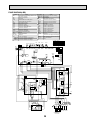
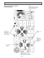
REFRIGERANT SYSTEM DIAGRAM
PUHZ-W50VHA(-BS)
PUHZ-W85VHA(-BS)
P-Sensor
TH7
CHECK/V
REV/V
S/V
TH3
CHECK/V
CHECK/V
Water OUT
Distributor
H/P SW
Plate HEX
Receiver
TH4
TH8
Strainer
(#100)
TH32
TH33 (W50 only)
P/B
Strainer
(#100)
COMP
LEV-B
Water IN
LEV-A
TH6
Strainer(#100)
Strainer(#100)
Refrigerant flow in heating
Refrigerant flow in cooling
Symbol
COMP
H/P SW
Plate HEX
REV/V
S/V
CHECK/V
P-Sensor
P/B
LEV-A
LEV-B
TH32
TH3
TH4
TH6
TH7
TH8
TH33
Receiver
Detail
Part name
Compressor
High pressure switch (63H)
Plate Heat Exchanger
Reversing (4-way) valve (21S4)
Solenoid valve
Check valve
Pressure sensor (63HS)
Power board
Linear expansion valve -A
Linear expansion valve -B
Inlet water temperature thermistor
Liquid temperature thermistor
Discharge temperature thermistor
Plate HEX liquid temperature thermistor
Ambient temperature thermistor
Heatsink temperature thermistor
Comp.shell temperature thermistor
Receiver
DC inverter twin rotary compressor (Mitsubishi Electric Corporation)
For protection (OFF:4.15MPa)
ACH30 - 30 Plates (Alfa Laval):W50 / ACH30 - 40 Plates (Alfa Laval):W85
Change the refrigerant circuit (Heating / Cooling) and for Defrosting
For production test use
High pressure / Low pressure / For production test use
For calculation of the condensing temperature from high pressure
Inverter power board
Heating:Secondary LEV Cooling:Primary LEV
Heating:Primary LEV
Cooling:Secondary LEV
For freeze protection and for compressor frequency control
Heating:Evaporating temperature Cooling:Sub cool liquid temperature
For LEV control and for compressor protection
Heating:Sub cool liquid temperature Cooling:Evaporating temperature
For fan control and for compressor frequency control
For power board protection
For compressor protection
For accumulation of refrigerant
19
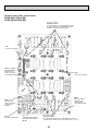
PUHZ-HW112YHA(-BS) PUHZ-HW140VHA(-BS) PUHZ-HW140YHA(-BS)
P-Sensor
TH7
STOP VALVE
REV/V
TH3
CHECK/V
CHECK/V
Water OUT
Strainer
(#100)
Power
Receiver
Plate HEX
MUFFLER
TH33
TH4
TH8
Strainer
(#100)
TH32
LEV-B
TH6
P/B
Strainer(#100)
LEV-A
Strainer
(#100)
Water IN
Distributor
H/P SW
L/P SW
LEV-C
INJ Port
COMP
HIC
Strainer(#100)
Refrigerant flow in heating
Refrigerant flow in cooling
Symbol
COMP
H/P SW
L/P SW
Plate HEX
REV/V
STOP VALVE
CHECK/V
P-Sensor
P/B
LEV-A
LEV-B
LEV-C
TH33
TH32
TH3
TH4
TH6
TH7
TH8
Power Receiver
HIC
Detail
Part name
Compressor
High pressure switch (63H)
Low pressure switch (63L)
Plate Heat Exchanger
Reversing (4-way) valve (21S4)
Stop valve
Check valve
Pressure sensor (63HS)
Power board
Linear expansion valve -A
Linear expansion valve -B
Linear expansion valve -C
Suction temperature thermistor
Inlet water temperature thermistor
Liquid temperature thermistor
Discharge temperature thermistor
Plate HEX liquid temperature thermistor
Ambient temperature thermistor
Heatsink temperature thermistor
Power Receiver
Heat interchange circuit
DC inverter scroll compressor (Mitsubishi Electric Corporation)
For protection (OFF:4.15MPa)
For protection (OFF:-0.03MPa)
ACH50 - 50 Plates (Alfa Laval)
Change the refrigerant circuit (Heating / Cooling) and for Defrosting
For production test use
High pressure / Low pressure / For production test use
For calculation of the condensing temperature from high pressure
Inverter power board
Heating:Secondary LEV Cooling:Primary LEV
Heating:Primary LEV
Cooling:Secondary LEV
For HIC (heating only)
For LEV control
For freeze protection and for compressor frequency control
Heating:Evaporating temperature Cooling:Sub cool liquid temperature
For LEV control and for compressor protection
Heating:Sub cool liquid temperature Cooling:Evaporating temperature
For fan control and for compressor frequency control
For power board protection
For accumulation of refrigerant
For high heating capacity
20
8
TROUBLESHOOTING
8-1. TROUBLESHOOTING
<Error code display by self-diagnosis and actions to be taken for service (summary)>
Present and past error codes are logged and displayed on the control board of outdoor unit. Actions to be taken for service,
which depends on whether or not the trouble is reoccurring at service, are summarized in the table below. Check the contents
below before investigating details.
Unit conditions at service
Error code
Actions to be taken for service (summary)
Displayed
Judge what is wrong and take a corrective action according
to “8-3. Self-diagnosis action table”.
The trouble is reoccurring.
Not displayed
Conduct troubleshooting and ascertain the cause of the
trouble.
Logged
Consider the temporary defects such as the work of
protection devices in the refrigerant circuit including
compressor, poor connection of wiring, noise and etc.
Re-check the symptom, and check the installation
environment, refrigerant amount, weather when the
trouble occurred, matters related to wiring
and etc.
Reset error code logs and restart the unit after finishing
service.
There is no abnormality in electrical component,
controller board, and etc.
Not logged
Re-check the abnormal symptom.
Conduct troubleshooting and ascertain the cause of the
trouble.
Continue to operate unit for the time being if the cause
is not ascertained.
There is no abnormality concerning of parts such as
electrical component, controller board, and etc.
The trouble is not reoccurring.
8-2. CHECK POINT UNDER TEST RUN
Before test run
• After installation of outdoor units, piping work and electric wiring work, re-check that there is no water leakage, loosened connections and incorrect polarity.
• Measure impedance between the ground and the power supply terminal block (L, N) on the outdoor unit by 500 V Megger
and check that it is 1.0 M or over.
• Turn on power supply 12 hours before test run in order to protect compressor.
• Make sure to read operation manual before test run. (Especially items to secure safety.)
21
8-3. SELF-DIAGNOSIS ACTION TABLE
<Abnormalities detected when the power is turned on>
Error Code
None
Abnormal point and detection method
—
Case
Judgment and action
1 No voltage is supplied to termi- 1 Check following items.
nal block(TB1) of outdoor unit.
a) Power supply breaker
a) Power supply breaker is
turned off.
b) Connection of power supply terminal
b) Contact failure or disconnecblock.(TB1)
tion of power supply terminal
c) Open phase (L or N phase)
c) Connection of power supply terminal
block.(TB1)
2 Electric power is not charged to 2 Check following items.
power supply terminal of outa) Connection of power supply terminal
door power circuit board.
block.(TB1)
a) Contact failure of power
b) Connection of terminal on outdoor
supply terminal
power circuit board.
b) Open phase on the outdoor
W50 :
Check connection of the connector R or S.
power circuit board
Refer to 8-6.
W50 :
W85 :
Disconnection of connector R or S
Check connection of the connector TABT or TABS.
W85 :
Refer to 8-6.
Disconnection of connector
HW140V :
TABT or TABS
Check connection of the connector LI or NI.
HW140V :
Refer to 8-6.
Disconnection of connector LI, NI
3 Check connection of the connector (CNDC)
3 Electric power is not supplied
on the outdoor controller circuit board.
to outdoor controller circuit
Check connection of the connector, LD1 and
board.
LD2 for W50 and CNDC for W85/HW112/
a) Disconnection of connector
HW140, on the outdoor power circuit board
(CNDC)
(V) / noise filter(Y).Refer to 8-6.
.
4 Disconnection of reactor (DCL 4 Check connection of reactor. (DCL or ACL)
W50 : Check connection of “LO” and
or ACL)
“NO” on the outdoor noise filter circuit board.
Check connection of “R” and “S” on the
outdoor power circuit board.
W85 : Check connection of “L1” and “L2” on
the active filter module.(ACTM)
Refer to 8-6.
HW140V :
Check connection of "DCL1" and "DCL2" on
5 Disconnection of outdoor noise
the outdoor power circuit board.
filter circuit board or parts failure in outdoor noise filter circuit 5 a) Check connection of outdoor noise filter
circuit board. Refer to 8-6.
board
b) Replace outdoor noise filter circuit board.
Refer to 8-6.
6 Defective outdoor power circuit 6 Replace outdoor power circuit board.
board
7 Defective outdoor controller
circuit board
63L connector open
Abnormal if 63L connector circuit is open
for 3 minutes continuously from being
switched on.
63L: Low-pressure switch
F3
7 Replace controller board (When items
above are checked but the units can not be
repaired.)
1 Disconnection or contact failure 1 Check connection of 63L connector on
of 63L connector on outdoor
outdoor controller circuit board.
controller circuit board
Refer to 8-6.
2 Disconnection or contact failure 2 Check the 63L side of connecting wire.
of 63L
3 63L is working due to refriger- 3 Check refrigerant pressure.
ant leakage or defective parts.
Charge additional refrigerant.
Check continuity of 63L.
Replace low pressure switch if it is defective.
4 Defective outdoor controller
4 Replace outdoor controller circuit board.
circuit board
22
Error Code
F5
F9
EA
Eb
63H connector open
Abnormal if 63H connector circuit is open
for 3 minutes continuously from being
switched on.
63H: High-pressure switch
1 Disconnection or contact failure
of 63H connector on outdoor
controller circuit board
2 Disconnection or contact failure
of 63H
3 63H is working due to defective
parts.
4 Defective outdoor controller
circuit board
1 Disconnection or contact failure
2 connector open
of connector (63H,63L) on
Abnormal if both 63H and 63L connector
outdoor controller circuit board.
circuits are open for 3 minutes continuously
2 Disconnection or contact failure
from being switched on.
of 63H, 63L
63H: High-pressure switch
3 63H and 63L are working due
63L: Low-pressure switch
to defective parts.
4 Defective outdoor controller
board.
Miswiring of Interface unit/Flow temp.
controller-outdoor unit connecting wire
1. Outdoor controller circuit board can
automatically check the number of
connected Interface unit/Flow temp. controller. Abnormal if the number cannot be
checked automatically due to miswiring
of Interface unit/Flow temp. controlleroutdoor unit connecting wire and etc.
after power is turned on for 4 minutes.
2. Abnormal if outdoor controller circuit
board recognizes excessive number of
Interface unit/Flow temp. controller.
Miswiring of Interface unit/Flow temp.
controller-outdoor unit connecting wire
(converse wiring or disconnection)
Outdoor controller circuit board can
automatically set the unit number of
Interface unit/Flow temp. controller.
Abnormal if the Interface unit/Flow temp.
controller number cannot be set within 4
minutes after power on because of miswiring (converse wiring or disconnection) of
Interface unit/Flow temp. controller-outdoor
unit connecting wire.
Start-up time over
The unit cannot finish start-up process
within 4 minutes after power on.
EC
Case
Abnormal point and detection method
Contact failure or miswiring of
Interface unit/Flow temp. controlleroutdoor unit connecting wire
Diameter or length of Interface
unit/Flow temp. controller-outdoor unit connecting wire is out
of specified capacity.
Excessive number of Interface
unit/Flow temp. controller is
connected to 1 outdoor unit.
(2 units or more)
Defective transmitting receiving
circuit of outdoor controller
circuit board
Defective transmitting receiving
circuit of Interface/Flow temp.
controller board
Noise has entered into power
supply or Interface/Flow temp.
controller-outdoor unit connecting wire.
Contact failure or miswiring of
Interface unit/Flow temp. controller-outdoor unit connecting wire
Diameter or length of Interface
unit/Flow temp. controller-outdoor unit connecting wire is out
of specified capacity.
Defective transmitting receiving circuit
of outdoor controller circuit board
Defective transmitting receiving
circuit of Interface/Flow temp.
controller board
Noise has entered into power supply
or Interface unit/Flow temp. controller-outdoor unit connecting wire.
Contact failure of Interface unit
/Flow temp. controller-outdoor
unit connecting wire
Diameter or length of Interface
unit/Flow temp. controlleroutdoor unit connecting wire is
out of specified capacity.
Noise has entered into power supply or Interface unit/Flow temp.
controller-outdoor unit connecting
wire.
23
Judgment and action
1 Check connection of 63H connector on
outdoor controller circuit board.
Refer to 8-6.
2 Check the 63H side of connecting wire.
3 Check for continuity of 63H.
Replace high pressure switch if it is defective.
4 Replace outdoor controller circuit board.
1 Check connection of connector (63H,63L) on
outdoor controller circuit board.
Refer to 8-6.
2 Check the 63H and 63L side of connecting
wire.
3 Check continuity of 63H and 63L.
Replace the pressure switch if it is defective.
4 Replace outdoor controller circuit board.
Check disconnection or looseness or polarity
of Interface unit/Flow temp. controller-outdoor
unit connecting wire of Interface unit/Flow
temp. controller and outdoor units.
Check diameter and length of Interface unit/
Flow temp. controller-outdoor unit connecting
wire.
Total wiring length: 80 m
(Including wiring connecting each Interface
unit/Flow temp. controller unit and between
Interface unit/Flow temp. controller and outdoor unit)
Also check if the connection order of flat
cable is S1, S2, S3.
Check the number of Interface unit/Flow
temp. controller that is connected to 1 outdoor unit. (If EA is detected.)
~
Turn the power off once, and on again to
check.
Replace outdoor controller circuit board or
Interface/Flow temp. controller board
if abnormality occurs again.
Check transmission path, and remove the
cause.
The descriptions above,
and EC.
- , are for EA, Eb
<Abnormalities detected while unit is operating>
Error Code
Abnormal point and detection method
High pressure (High-pressure switch
63H activated)
Abnormal if high-pressure switch 63H is
activated ( w ) during compressor operation.
w 4.15 MPa
63H: High-pressure switch
U1
Case
1 Decreased water flow
2 Clogged filter of water pipe
3 Dirt of plate heat exchanger
4 Locked water pump
5 Malfunction of water pump
6 Clogged or broken pipe
7 Locked outdoor fan motor
8 Malfunction of outdoor fan
motor
9 Short cycle of outdoor unit
0 Dirt of outdoor heat exchanger
1 Decreased airflow caused by
defective inspection of outside
temperature thermistor
(It detects lower temperature
than actual temperature.)
2 Disconnection or contact failure
of connector (63H) on outdoor
controller board
3 Disconnection or contact failure
of 63H connection
4 Defective outdoor controller
board
5 Defective operation of linear
expansion valve
6 Malfunction of fan driving
circuit
Judgment and action
1~5Check water circuit and repair the defect.
6 Check piping and repair the defect.
7~0 Check outdoor unit and repair the defect.
1 Check the detected temperature of outside
temperature thermistor on LED display.
(SW2: Refer to 8-7.)
2~4 Turn the power off and check F5 is
displayed when the power is turned on again.
When F5 is displayed, refer to “Judgment
and action” for F5.
5 Check linear expansion valve.
Refer to 8-5.
6 Replace outdoor controller board.
High discharging temperature
Abnormal if discharge temperature
thermistor (TH4) exceeds 125: or 110:
continuously for 5 minutes.
Abnormal if during defrosting discharge
temperature thermistor (TH4) exceeds
110: continuously for 30 minutes.
U2
U3
1 Overheated compressor
1 Check intake super heat.
operation caused by insufficient
Check leakage of refrigerant.
refrigerant
Charge additional refrigerant.
2 Defective thermistor
23 Turn the power off and check if U3 is dis3 Defective outdoor controller
played when the power is turned ON again.
board
When U3 is displayed, refer to “Judgement
4 Defective operation of linear
and action” for U3.
expansion valve
4 Check linear expansion valve.
High comp. surface temperature (W50 only) 5 In the case of the unit does not
Refer to 8-5.
restart :
Abnormal if comp. surface temperature
Detection temp. of thermistor
(TH33) exceeds 125:.
(TH33) ] 95:
In the case of high comp. surface temperature error, compressor does not restart
unless the thermistor (TH33) becomes less
than 95:.
Open/short circuit of discharge
1 Disconnection or contact
1 Check connection of connector (TH4/TH32)
temperature thermistor (TH4)/comp. suron the outdoor controller circuit board.
failure of connector (TH4/TH33)
Check the lead wire for thermistor (TH4/
face thermistor (TH33/W50 only)
on the outdoor controller circuit
TH32). Refer to 8-6.
Abnormal if open (3: or less) or short
board.
2 Check resistance value of thermistor (TH4/
(217: or more) is detected during
2 Defective thermistor
TH32) or temperature on LED display.
compressor operation.
3 Defective outdoor controller
(Thermistor/TH4/TH32: Refer to 8-5.)
(Open (3: or less) detection is inoperacircuit board
(SW2: Refer to 8-7.)
tive for 10 minutes of compressor starting
3 Replace outdoor controller board.
process and for 10 minutes after or during
defrosting.)
24
Error Code
Abnormal point and detection method
Open/short of outdoor unit thermistors 1 Disconnection or contact failure 1 Check connection of connector (TH3, TH32,
(TH3, TH32, TH33, TH6, TH7, and TH8)
TH33, TH6/TH7) on the outdoor controller circuit
of connectors
board.
Abnormal if open or short is detected
Outdoor controller circuit
Check connection of connector (CN3) on the
during compressor operation.
board: TH3, TH32, TH33,
outdoor power circuit board.
Open detection of thermistors TH3, TH32
TH6/TH7
Check the lead wire for thermistor (TH3,
and TH6 is not detected for 10 seconds to
Outdoor power circuit board:
TH32, TH33, TH6, TH7, TH8). Refer to 8-6.
10 minutes after compressor starting and
CN3
2 Check resistance value of thermistor (TH3,
10 minutes after and during defrosting.
2 Defective thermistor
TH32, TH33, TH6, TH7, TH8) or check temCheck which unit has abnormality in its
3 Defective outdoor controller
perature on LED display.
thermistor by switching the mode of
circuit board
(Thermistor/TH3, TH32, TH33, TH6, TH7,
SW2.
TH8: Refer to 8-5.)
(Refer to 8-7.)
(SW2: Refer to 8-7)
HW112, 140
3 Replace outdoor controller circuit board.
Heatsink thermistor (TH8) is in the power
module.
)
(
U4
Judgment and action
Case
Symbol
TH3
TH32
TH33
TH6
TH7
TH8
Thermistors
Name
Thermistor <Liquid temperature>
Thermistor <Inlet water temperature>
Thermistor <Suction pipe temperature> HW112, 140
Thermistor <Plate HEX liquid temperature>
Thermistor <Ambient temperature>
Thermistor <Heatsink temperature> W50,85
TH8 Internal thermistor HW112,140
Temperature of heatsink
Abnormal if heatsink thermistor (TH8)
detects temperature indicated below.
W50V ••••••••••••••••••• 77°C
W85V ••••••••••••••••••• 77°C
HW140V ••••••••••••••• 84°C
HW112Y ••••••••••••••• 95°C
HW140Y ••••••••••••••• 95°C
U5
U6
U7
Open detection Short detection
– 40 or below
– 40 or below
– 40 or below
– 40 or below
– 40 or below
– 35 or below
– 35 or below
1 The outdoor fan motor is
locked.
2 Failure of outdoor fan motor
3 Air flow path is clogged.
4 Ambient temperature is high.
5 Defective thermistor
6 Defective input circuit of
outdoor power circuit board
7 Failure of outdoor fan drive
circuit
90 or above
102 or above
90 or above
90 or above
90 or above
102 or above
170 or above
12 Check outdoor fan.
3 Check air flow path for cooling.
4 Check if there is something which causes
temperature rise around outdoor unit.
(Upper limit of ambient temperature is 46:.)
Turn off power, and on again to check if U5
is displayed within 30 minutes.
If U4 is displayed instead of U5, refer to
error code U4.
5 Check resistance value of thermistor (TH8)
or temperature by microcomputer.
(Thermistor/TH8: Refer to 8-5.)
(SW2: Refer to 8-7)
6 Replace outdoor power circuit board.
7 Replace outdoor controller circuit board.
Power module
1 Defective outdoor power circuit
Check abnormality by driving power module
board
in case overcurrent is detected.
2 Decrease of power supply voltage
(UF or UP error condition)
3 Loosens, disconnection or
reverse of compressor wiring
connection
4 Defective compressor
1 Replace outdoor power circuit board.
2 Check facility of power supply.
3 Correct the wiring (U•V•W phase) to
compressor. Refer to 8-6 (Outdoor power
circuit board).
4 Check compressor referring to 8-4.
Too low superheat due to low discharge 1 Disconnection or loose
temperature
connection of discharge
temperature thermistor (TH4)
Abnormal if discharge superheat is
continuously detected -15: or less for
2 Defective holder of discharge
temperature thermistor
3 minutes even though linear expansion
valve has minimum open pulse after com- 3 Disconnection or loose connection
of linear expansion valve’s coil
pressor starts operating for 10 minutes.
4 Disconnection or loose
connection of linear expansion
valve’s connector
5 Defective linear expansion valve
12 Check the installation conditions of
discharge temperature thermistor (TH4).
25
3 Check the coil of linear expansion valve.
Refer to 8-5.
4 Check the connection or contact of LEV-A and
LEV-B on outdoor controller circuit board.
5 Check linear expansion valve.
Refer to 8-4.
Error Code
Abnormal point and detection method
U8
Outdoor fan motor
Abnormal if rotational frequency of the fan
motor is not detected during DC fan motor
operation.
Fan motor rotational frequency is abnormal if;
• 100 rpm or below detected continuously
for 15 seconds at 20: or more outside
air temperature
• 50 rpm or below or 1500 rpm or more
detected continuously for 1 minute.
Overvoltage or voltage shortage and
synchronous signal to main circuit
U9
Abnormal if any of followings are detected
during compressor operation;
• Decrease of DC bus voltage to 310V
(50-140V only)
• Instantaneous decrease of DC bus voltage
50-140V : 200V
112,140Y : 350V
• Increase of DC bus voltage to
50V : 420V
85-140V : 400V
112,140Y : 760V
• Decrease of input current of outdoor unit
to 0.1A only if operation frequency is
more than or equal to 40Hz or compressor current is more than or equal to 6A.
* Check U9 error detail (SW2 all ON)
Refer to 8-7.
Ud
UF
Overheat protection
Abnormal if outdoor pipe thermistor (TH3)
detects 70: or more or condensing
temperature of pressure sensor (63HS)
detects 70: or more during compressor
operation.
Compressor overcurrent interruption
(When compressor locked)
Abnormal if overcurrent of DC bus or
compressor is detected within 30 seconds
after compressor starts operating.
Case
1 Failure in the operation of
the DC fan motor
2 Failure in the outdoor circuit
controller board
1 Decrease of power supply voltage
2 Disconnection of compressor
wiring
3 Defective power circuit board
Judgment and action
1 Check or replace the DC fan motor.
2 Check the voltage of the outdoor circuit
controller board during operation.
3 Replace the outdoor circuit controller
board. (when the failure is still indicated
even after performing the remedy 1
above.)
1 Check the facility of power supply.
2 Correct the wiring (U•V•W phase) to compressor. Refer to 8-6 (Outdoor power circuit
board).
3 Replace power circuit board.
4 Disconnection or loose connec- 4 Check CN52C wiring.
tion of CN52C (50-140V)
5 Defective PFC module of outdoor power board (50V)
6 Defective ACT module
(85V)
7 Defective ACT module drive
circuit of outdoor power circuit
board (85V)
8 Disconnection or loose connection of CNAF (85V)
9 Defective outdoor converter circuit board (112, 140Y)
0 Defective 52C drive circuit of
outdoor controller circuit board
(50-140V)
1 Disconnection or loose
connection of CN5 on the
outdoor power circuit board
(50, 85V)
2 Defective 52C drive circuit of
outdoor power circuit board
(112, 140Y)
3 Disconnection or loose
connection of CN2 on the
outdoor power circuit board
5 Replace outdoor power circuit board.
(50V)
6 Replace ACT module. (85V)
1 Defective outdoor fan (fan
motor) or short cycle of outdoor unit during cooling operation
2 Defective outdoor pipe
thermistor (TH3)
3 Defective outdoor controller
board
4 Defective pressure sensor
1 Check outdoor unit air passage.
1 Decrease of power supply voltage
2 Looseness, disconnection or
converse of compressor wiring
connection
3 Defective compressor
4 Defective outdoor power board
5 Decreased water flow
6 Clogged filter of water pipe
7 Clogged plate heat exchanger
8 Locked water pump
9 Malfunction of water pump
1 Check facility of power supply.
26
7 Replace outdoor power circuit board. (85V)
8Check CNAF wiring. (85V)
9 Replace outdoor converter circuit board.
(112, 140Y)
0 Replace outdoor controller circuit board.
(50-140V)
1 Check CN5 wiring on the outdoor power circuit board. (50, 85V)
Refer to 8-6.
2 Replace outdoor power circuit board.
(112, 140Y)
3 Check CN2 wiring on the outdoor power circuit board. Refer to 8-6.
23 Turn the power off and on again to check
the error code. If U4 is displayed, follow the
U4 processing direction.
4 Check pressure by microcomputer.
(Pressure sensor/ 63HS)
(SW2: Refer to 8-7.)
2 Correct the wiring (U•V•W phase) to
compressor.
Refer to 8-6 (Outdoor power circuit board).
3 Check compressor. Refer to 8-4.
4 Replace outdoor power circuit board.
5~9 Check water circuit and repair the defect.
Error Code
UH
Abnormal point and detection method
Low pressure (63L worked)
Abnormal if 63L is worked (under -0.03
MPa) during compressor operation.
63L: Low-pressure switch
UL
UP
E0
or
E4
E1
or
E2
Case
Judgment and action
Current sensor error or input current error 1 Disconnection of compressor
1 Correct the wiring (U•V•W phase) to com·Abnormal if current sensor detects –1.0 A
wiring
pressor. Refer to 8-6 (Outdoor power circuit
to 1.0 A during compressor operation.
board).
2 Defective circuit of current
(This error is ignored during test run.)
sensor on outdoor power
2 Replace outdoor power circuit board.
·Abnormal if 40 A of input current is detected
circuit board
3 Check the facility of power supply.
or 37 A or more of input current is detected 3 Decrease of power supply voltfor 10 seconds continuously. (HW140V only)
age
1 Stop valve of outdoor unit is
closed during operation.
2 Disconnection or loose connection of connector (63L) on
outdoor controller board
3 Disconnection or loose connection of 63L
4 Defective outdoor controller
board
5 Leakage or shortage of refrigerant
6 Malfunction of linear expansion
valve
Compressor overcurrent interruption
1 Decrease of power supply voltage
Abnormal if overcurrent DC bus or com2 Looseness, disconnection or
pressor is detected after compressor starts
converse of compressor wiring
operating for 30 seconds.
connection
3 Defective fan of outdoor units
4 Short cycle of indoor/outdoor
units
5 Defective input circuit of outdoor controller board
6 Defective compressor
7 Decreased water flow
8 Clogged filter of water pipe
9 Clogged plate heat exchanger
0 Locked water pump
1 Malfunction of water pump
Remote controller transmission error
(E0)/signal receiving error (E4)
Abnormal if main or sub remote controller cannot receive any transmission
normally from Interface unit/Flow temp.
controller of refrigerant address “0” for 3
minutes.
(Error code: E0)
Abnormal if sub-remote controller could
not receive any signal for 2 minutes.
(Error code: E0)
Abnormal if Interface/Flow temp. controller board can not receive any data
normally from remote controller board or
from other Interface/Flow temp. controller board for 3 minutes. (Error code: E4)
Interface/Flow temp. controller board
cannot receive any signal from remote
controller for 2 minutes. (Error code: E4)
Remote controller control board
Abnormal if data cannot be read normally from the nonvolatile memory of the
remote controller control board.
(Error code: E1)
1 Check stop valve.
2~4 Turn the power off and on again to check
if F3 is displayed on restarting.
If F3 is displayed, follow the F3 processing
direction.
5 Correct to proper amount of refrigerant.
6 Check linear expansion valve.
Refer to 8-5.
1 Check facility of power supply.
2 Correct the wiring (U•V•W phase) to compressor. Refer to 8-6 (Outdoor power circuit
board).
3 Check outdoor fan.
4 Solve short cycle.
5 Replace outdoor controller circuit board.
6 Check compressor.
Refer to 8-4.
w Before the replacement of the outdoor
controller circuit board, disconnect the wiring
to compressor from the outdoor power circuit
board and check the output voltage among
phases, U, V, W, during test run. No defect
on board if voltage among phases (U-V, V-W
and W-U) is same. Make sure to perform the
voltage check with same performing frequency.
7~1 Check water circuit and repair the defect.
Contact failure at transmission
Check disconnection or looseness of
Interface unit/Flow temp. controller unit or
wire of remote controller
transmission wire of remote controller.
All remote controllers are set
Set one of the remote controllers “main”, If
as “sub” remote controller. In
there is no problem with the action above.
this case, E0 is displayed on
Check wiring of remote controller.
remote controller, and E4 is
• Total wiring length: max. 500 m
displayed at LED (LED1, LED2)
(Do not use cablex 3 or more.)
on the outdoor controller circuit
• The number of connecting remote controlboard.
ler: max. 2 units
Miswiring of remote controller
Defective transmitting receiving When it is not the above-mentioned problem of
circuit of remote controller
~
Noise has entered into the
Diagnose remote controllers.
a) When “RC OK” is displayed, remote contransmission wire of remote
trollers have no problem.
controller.
Turn the power off, and on again to check.
If abnormality generates again, replace
Interface/Flow temp. controller board.
b) When “RC NG” is displayed, replace
remote controller.
c) When “RC E3” or “ERC 00-66” is displayed, noise may be causing abnormality.
Defective remote controller
Abnormal if the clock function of remote
controller cannot be operated normally.
(Error code: E2)
27
Replace remote controller.
Error Code
E3
or
E5
E6
E8
E9
EF
Ed
Abnormal point and detection method
Case
Judgment and action
Remote controller transmission error
(E3)/signal receiving error (E5)
1 Abnormal if remote controller could not find
blank of transmission path for 6 seconds
and could not transmit.
(Error code: E3)
2 When remote controller receives the
transmitted data same time and compares
these data. Abnormal if the data is judged
to be different for 30 continuous times.
(Error code: E3)
1 2 remote controllers are set as 1 Set a remote controller to main, and the
“main.”
other to sub.
(In case of 2 remote controllers)
2 Defective transmitting receiving 2~4 Diagnose remote controller.
a) When “RC OK” is displayed, remote concircuit of remote controller
trollers have no problem.
3 Defective transmitting receiving
Turn the power off, and on again to check.
circuit of Interface/Flow temp.
When becoming abnormal again, replace
controller board
indoor controller board.
4 Noise has entered into transb) When “RC NG” is displayed, replace
mission wire of remote controlremote controller.
ler.
1 Abnormal if Interface/Flow temp. controller
c) When “RC E3” or “ERC 00-66” is disboard could not find blank of transmission
played, noise may be causing abnormalpath. (Error code: E5)
ity.
2 When Interface/Flow temp. controller
receives the transmitted data same time
and compares these data. Abnormal if the
data is judged to be different for 30 continuous times. (Error code: E5)
Interface unit/Flow temp. controller-outdoor unit communication error (Signal
receiving error)
1 Abnormal if Interface/Flow temp. controller
board cannot receive any signal normally for
6 minutes after turning the power on.
2 Abnormal if Interface/Flow temp. controller
board cannot receive any signal normally for
3 minutes.
1 Contact failure, short circuit or, * Check LED display on the outdoor control circuit
miswiring (converse wiring) of
board. (Connect A-control service tool, PACInterface unit/Flow temp. conSK52ST.)
troller-outdoor unit connecting 1 Check disconnection or looseness of
wire
Interface unit/Flow temp. controller-outdoor
2 Defective transmitting receiving
unit connecting wire of Interface unit/Flow
circuit of Interface/Flow temp.
temp. controller or outdoor unit.
controller board
3 Defective transmitting receiving 2~4 Turn the power off, and on again to check.
circuit of Interface/Flow temp.
If abnormality generates again, replace
controller board
Interface/Flow temp. controller board or
outdoor controller circuit board.
4 Noise has entered into
Interface unit/Flow temp. controller-outdoor unit connecting
wire.
Interface unit/Flow temp. controller-outdoor unit communication error (Signal
receiving error)
(Outdoor unit)
(1) Abnormal if outdoor controller circuit
board could not receive anything
normally for 3 minutes.
1 Contact failure of Interface unit/
Flow temp. controller-outdoor
unit connecting wire
2 Defective communication circuit
of outdoor controller circuit board
3 Defective communication circuit of
Interface/Flow temp. controller board
4 Noise has entered into Interface unit/
Flow temp. controller-outdoor unit
connecting wire.
Interface unit/Flow temp. controller1 Interface unit/Flow temp. controller-outdoor unit connecting
outdoor unit communication error
wire has contact failure.
(Transmitting error) (Outdoor unit)
(1) Abnormal if “0” receiving is detected 30 2 Defective communication circuit
of outdoor controller circuit board
times continuously though outdoor controller circuit board has transmitted “1”. 3 Noise has entered power supply.
4 Noise has entered Interface
(2) Abnormal if outdoor controller circuit
unit/Flow temp. controllerboard could not find blank of transmission
outdoor unit connecting wire.
path for 3 minutes.
Non defined error code
This code is displayed when non defined
error code is received.
1 Check disconnection or looseness of
Interface unit/Flow temp. controller-outdoor
unit connecting wire of Interface unit/Flow
temp. controller or outdoor unit.
2~4 Turn the power off, and on again to
check. Replace Interface/Flow temp. controller board or outdoor controller circuit
board if abnormality is displayed again.
1 Check disconnection or looseness of
Interface unit/Flow temp. controller-outdoor
unit connecting wire.
2~4 Turn the power off, and on again to
check. Replace outdoor controller circuit
board if abnormality is displayed again.
1 Noise has entered transmission 12 Turn the power off, and on again to check.
wire of remote controller.
Replace Interface/Flow temp. controller
2 Noise has entered Interface
board or outdoor controller circuit board if
unit/Flow temp. controllerabnormality is displayed again.
outdoor unit connecting wire.
Serial communication error
1 Wire disconnection or contact 12 Check connection of each connector CN2
Abnormal if serial communication between
and CN4 between the outdoor controller
failure of connector CN2
outdoor controller circuit board and outdoor
circuit board and the outdoor power circuit
between the outdoor controller
power circuit board is defective.
circuit board and the outdoor
board.
power circuit board
2 Wire disconnection or contact
failure of connector CN4
between the outdoor controller
circuit board and the outdoor
power circuit board
3 Defective communication circuit 3 Replace outdoor power circuit board.
of outdoor power circuit board
4 Defective communication circuit 4 Replace outdoor controller circuit board.
of outdoor controller circuit board
for outdoor power circuit board
28
Error Code
Abnormal point and detection method
P6
Judgment and action
Case
Freezing/overheating protection is working
(1) Freezing protection <Cooling mode>
Abnormal if plate heat exchanger pipe
temperature (TH6) stays at -5: or lower
for 10 seconds or abnormal if plate heat
exchanger pipe thermistor (TH6) stays at
-2: or lower and compressor operation
frequency is minimum for 5 minutes
after compressor starts operating for 6
minutes.
<Cooling mode>
12 Check water piping.
<Cooling mode>
1 Reduced water flow
· Clogged filter
· Leakage of water
2 Low temperature
· Low-load
· Inlet water is too cold.
3 Defective water pump
3 Check water pump.
4 Check outdoor fan motor.
4 Defective outdoor fan control
5~7 Check operating condition of refrigerant
5 Overcharge of refrigerant
(2) Overheating protection <Heating mode> 6 Defective refrigerant circuit
circuit.
Abnormal if condensing temperature of
(clogs)
pressure sensor (63HS) detects
7 Malfunction of linear expansion 7 Check linear expansion valve.
Tcond. : or more and compressor opervalve
ation frequency is less than or equal to
30 Hz. Detection is inoperative during
<Heating mode>
<Heating mode>
defrosting.
12 Check water piping.
1 Reduced water flow
· Clogged filter
· Leakage of water
2 High temperature
· Over-load
· Inlet water is too warm.
3 Check water pump.
3 Defective water pump
45 Check operating condition of refrigerant
4 Overcharge of refrigerant
circuit.
5 Defective refrigerant circuit
(clogs)
6 Malfunction of linear expansion valve 6 Check linear expansion valve.
stage-a
stage-b
Tcond
stage-c
stage-d
stage-e
stage-f
stage-g
-19 -18
-18 -17
-16 -15
-15 -14
Tcond
P8
-13 -12
-12 -11
-11 -10
-8
-7
-3
-2
-9 -8
-6
-5
-3
-2
Ambient temperature (TH7) [ ]
Model stage-a stage-b stage-c stage-d stage-e stage-f stage-g
W50,85
63
61
59
57
54
51
48
HW112,140
63
62
61
60
59
57
Pipe temperature
1 Leakage or shortage of
Abnormal if the following conditions are
refrigerant
detected for continuously 3 minutes after
compressor starts operating for 10 minutes. 2 Malfunction of linear
expansion valve
1. Cooling mode
T63HS-TH7 [ 2: and
3 Refrigerant circuit is clogged
TH3-TH7 [ 4: or T63HS-TH3 < 0: and
with foreign objects.
TH32-TH6 [ 0: and
Compressor operation frequency is 61Hz or more. w Clogging occurs in the parts
which become below freezing
2. Heating mode
point when water enters in
T63HS-TH32 [ 2: and
refrigerant circuit.
TH6-TH32 [ 1: and
TH7-TH3 [ 1: and
4 Disconnection of thermistor
Compressor operation frequency is 61Hz or more.
holder.
T63HS: Condensing temperature of pressure
sensor (63HS)
Thermistor
TH3: Liquid temperature
TH32: Inlet water temperature
TH6: Plate HEX Liquid temperature
TH7: Ambient temperature
UE
[W50,85]
[HW112,140]
Abnormal pressure of pressure sensor 1 Disconnection or contact
(63HS)
failure of connector (63HS)
Abnormal if pressure sensor (63HS) detects
on the outdoor controller
0.1 MPa or less.
circuit board
Detection is inoperative for 3 minutes after 2 Defective pressure sensor
compressor starting and 3 minutes after
3 Defective outdoor controller
and during defrosting.
circuit board
29
51
1 Check intake superheat.
Check leakage of refrigerant.
2 Check linear expansion valve.
3 After recovering refrigerant, remove water
from entire refrigerant circuit under vacuum
more than 1 hour.
4 Check temperature display on outdoor
controller circuit board.
Temperature display is indicated by setting
SW2 of outdoor controller circuit board.
Check the holder of thermistor.
1 Check connection of connector (63HS) on
the outdoor controller circuit board.
Check breaking of the lead wire for thermistor (63HS).
2 Check pressure by microcomputer.
(Pressure sensor/ 63HS)
(SW2: Refer to 8-7.)
3 Replace outdoor controller board.
Abnormal point and detection method
Error Code
PE
Judgment and action
Case
Inlet water temperature
Abnormal if the following conditions are
detected for continuously 10 seconds.
1. Cooling mode
During compressor operation
TH32 < 3:
2. Heating mode (exclude defrosting)
During compressor operation
TH32 < -10:
1 Reduced water flow
· Clogged filter
· Leak of water
2 Low temperature
· Low-load
· Low temperature inlet water
3 Defective water pump
12 Check water piping.
4 Leakage or shortage of
refrigerant
4 Check intake superheat.
Check leakage of refrigerant.
3 Check water pump.
3. Defrosting mode
During compressor operation
TH32 < 0:
Thermistor
TH32: Inlet water temperature
8-4. HOW TO CHECK THE PARTS
PUHZ-W50VHA(-BS) PUHZ-W85VHA(-BS) PUHZ-HW112YHA(-BS)
PUHZ-HW140V/YHA(-BS)
Check points
Parts name
TH3: Liquid pipe
Disconnect the connector then measure the resistance with a tester.
temperature
(At the ambient temperature of 10~30)
TH4: Discharge
temperature
Normal
Abnormal
TH6: Plate Hex liquid
TH4/TH33(W50)
160k~410k
pipe temperature
TH3
TH7: Ambient
TH6
temperature
4.3k~9.6k
Open or short
TH7
TH8: Heatsink
temperature
TH33(HW112,140)
TH32: Inlet water
TH32
4.4k~9.8k
temperature
TH8
39k~105k
TH33:
Comp. surface
thermistor (W50),
Suction pipe temperature
(HW112,140)
Fan motor (MF1)
Solenoid valve coil
<Four-way valve>
(21S4)
Compressor
(MC)
Refer to the next page.
Measure the resistance between the terminals with a tester.
(At the ambient temperature of 20)
Normal
Abnormal
W50,85
HW112,140
2350±170
1435±150
Open or short
Measure the resistance between the terminals with a tester.
(Winding temperature 20)
U
Normal
Abnormal
V
W50
W85
HW140V
HW112,140Y
W
0.640
0.865~0.895
0.188
0.302
Open or short
Linear expansion valve Disconnect the connector then measure the resistance with a tester.
(LEV-A) (LEV-B)(LEV-C) (Winding temperature 20°C)
M
Gray
Orange
Red
Yellow
Black
1
2
3
4
5
6
Solenoid valve coil
<Bypass valve>
(SV) W50,85
Normal
Gray - Black
Gray - Red
Abnormal
Gray - Yellow
Gray - Orange
46±3Ω
Measure the resistance between the terminals with a tester.
(At the ambient temperature of 20)
Normal
Abnormal
1450±150
Open or short
30
Open or short
Check method of DC fan motor (fan motor / outdoor controller circuit board)
Notes
· High voltage is applied to the connector (CNF1, 2) for the fan motor. Give attention to the service.
· Do not pull out the connector (CNF1, 2) of the motor with the power supply on.
(It may damage the outdoor controller circuit board and fan motor.)
Self check
Symptom: The outdoor fan does not run.
Check fuse (F5) on outdoor controller
circuit board.
Is the fuse normal?
No
Replace fan motor.
Replace outdoor controller circuit board.
Yes
Wiring contact check
Check contact of fan motor connector
(CNF1)
Yes
Is there contact failure?
Recover wiring.
No
Power supply check
Measure the voltage on the outdoor controller circuit.
(W50/85 : Remove the connector CNF1. / HW112/140 : Remove the connectors CNF1 and CNF2.)
TEST POINT
VDC DC 280-330 V (between 1 (+) and 4 (-) of CNF1)
VCC DC 15 V
(between 5 (+) and 4 (-) of CNF1)
Is the voltage normal?
Yes
Replace fan motor.
No
Check fan motor rotation.
Replace outdoor controller circuit board.
OK
END
NG
Replace outdoor controller circuit board.
Check fan motor rotation.
OK
END
NG
Replace fan motor.
31
8-5. HOW TO CHECK THE COMPONENTS
<Thermistor feature chart>
50
Low temperature thermistors
<Liquid pipe> (TH3)
<Plate Hex liquid pipe> (TH6)
<Ambient> (TH7)
<Suction pipe> (TH33 for HW112,140)
40
Resistance (k)
• Thermistor
• Thermistor
• Thermistor
• Thermistor
Thermistor R0 = 15k' ± 3%
B constant = 3480 ± 2%
1
1
Rt =15exp{3480( 273+t – 273 )}
0:
10:
20:
25:
15k'
9.6k'
6.3k'
5.2k'
30:
40:
4.3k'
3.0k'
30
20
10
0
-20 -10 0 10 20 30 40 50
Temperature ()
200
Medium temperature thermistor
• Thermistor <Heatsink> (TH8)
Thermistor R50 = 17k' ± 2%
B constant = 4150 ± 3%
Resistance (k)
150
1
1
Rt =17exp{4150( 273+t – 323)}
0:
25:
50:
70:
90:
180k'
50k'
17k'
8k'
4k'
100
50
0
25
50
75
100
Temperature ()
125
500
High temperature thermistor
• Thermistor <Discharge pipe> (TH4)
• Thermistor <Comp. surface> (TH33 for W50)
400
Resistance (k)
Thermistor R120 = 7.465k' ± 2%
B constant = 4057 ± 2%
1
1
Rt =7.465exp{4057( 273+t – 393)}
20: 250k'
30: 160k'
40: 104k'
50: 70k'
60: 48k'
70:
34k'
80:
24k'
90: 17.5k'
100: 13.0k'
110: 9.8k'
300
200
100
0
32
25
50
75
Temperature ()
100
120
Low temperature thermistor
50
• Thermistor <Inlet water> (TH32)
Thermistor R0 = 15k' ± 2.5%
B constant = 3450 ± 2%
40
0:
10:
20:
25:
15k'
9.6k'
6.3k'
5.2k'
30:
40:
Resistance (k)
1
1
Rt =15exp{3450( 273+t – 273 )}
4.3k'
3.0k'
30
20
10
0
-20 -10
33
0 10 20 30 40 50
Temperature()
Linear expansion valve
(1) Operation summary of the linear expansion valve
• Linear expansion valve opens/closes through stepping motor after receiving the pulse signal from the outdoor controller board.
• Valve position can be changed in proportion to the number of pulse signal.
<Connection between the outdoor controller board and the linear expansion valve>
Outdoor controller board
DC12V
Gray
LEV
1
Drive circuit
3
M
2
1
5
4
6
Orange 3
Red
4
Yellow 5
Black
6
Connector LEV-A
LEV-B
LEV-C
<Output pulse signal and the valve operation>
Output
(Phase)
Output
1
2
3
5
4
6
8
1
ON ON OFF OFF OFF OFF OFF ON
2
OFF ON
3
OFF OFF OFF ON ON ON OFF OFF
4
OFF OFF OFF OFF OFF ON ON ON
ON ON OFF OFF OFF OFF
(2) Linear expansion valve operation
Valve position (capacity)
7
Opening a valve : 8
7
6
5
4
4
5
Closing a valve : 1
2
3
The output pulse shifts in above order.
3
6
2
7
1
8
8
1
• When linear expansion valve operation stops, all output phase
become OFF.
• When the switch is turned on, 700 pulse closing valve signal will be
sent till it goes to point in order to define the valve position. (The
pulse signal is being sent for about 20 seconds.)
• When the valve moves smoothly, there is no sound or vibration
occurring from the linear expansion valve: however, when the pulse
number moves from to or when the valve is locked, sound can
be heard.
No sound is heard when the pulse number moves from to in
case coil is burnt out or motor is locked by open-phase.
Close
Open
• Sound can be detected by placing the ear against the screw driver
handle while putting the screw driver to the linear expansion valve.
500 pulse
Opening a valve
all the way
Pulse number
Extra tightning (about 32 pulse)
34
(3) How to attach and detach the coil of linear expansion valve
<Composition>
Linear expansion valve is separable into the main body and the coil as shown in the diagram below.
Stopper
Main body
Coil
Lead wire
<How to detach the coil>
Hold the lower part of the main body (shown as A) firmly so that
the main body does not move and detach the coil by pulling it
upward.
Be sure to detach the coil holding main body firmly. Otherwise
pipes can bend due to pressure.
A
<How to attach the coil>
Hold the lower part of the main body (shown as A) firmly so that
the main body does not move and attach the coil by inserting it
downward into the main body. Then securely attach the coil stopper to main body. (At this time, be careful that stress is not added
to lead wire and main body is not wounded by lead wire.) If the
stopper is not firmly attached to main body, coil may be detached
from the main body and that can cause defective operation of linear expansion valve.
To prevent piping stress, be sure to attach the coil holding the
main body of linear expansion valve firmly. Otherwise pipe may
break.
Be sure to attach
the stopper.
A
35
8-6. TEST POINT DIAGRAM
Outdoor controller circuit board
PUHZ-W50VHA(-BS) PUHZ-W85VHA(-BS)
CNS
S1-S2: 220-240 V AC
<CAUTION> TEST POINT 1 is high voltage.
VCC (TEST POINT 2)
VDC (TEST POINT 1)
63H
(voltage between pins of C6B): DC 15 V High pressure switch
(voltage between pins of C5E)
: DC 280 V-330 V
+
CNDC
DC 280 V -380 V
Connect from outdoor power circuit
board.
–}
Communication +
power supply
D71 Voltage
–
24 V DC
CNAC
2 to 4: Power supply
for outdoor controller
circuit board
(220-240 V AC)
1 to 3:
Power supply for
interface unit/Flow
temp. controlleroutdoor unit connection wire
(220-240 V AC)
VSP
(voltage between pins
of C5B): DC 0 V (when
stopped), DC 1 – 6.5 V
(when operated)
VFG
(voltage between right
pins of PC5D, pin 3
and pin 4)
TH33
Thermistor (W50 only)
<Comp. shell temperature>
CN2
TH32
Connect to the outdoor power circuit
board (CN2).
1-5:
Power circuit board
Transmitting signal
to the controller circuit
board
(0-5 V DC)
2-5: Zero cross signal
(0-5 V DC)
3-4: Not used (W50)
18V DC (W85)
6-5: 16 V DC
7-5: 16 V DC
[5: – 1,2,6,7: + ]
Thermistor
<Inlet water temperature>
TH6
Thermistor
<Plate Hex liquid
temperature>
TH7
<Ambient temperature>
TH3
Thermistor
<Liquid temperature>
TH4
Thermistor
<Discharge>
21S4
Four-way
valve
SV2
Bypass valve
LEV-A,-B
Linear expansion valve
SV1
SW8
Drain hose
heater output
Function switch
CN4
SW5
Transmission
to outdoor
power circuit
board (CN4)
Function switch
SW6
Model select
SW1
Forced defrost,
detect history
record reset
CN52C
Connect to the outdoor noise
filter circuit board. (CN52C)
CNDM
SW10
1 to 2 :Input of low level Model select
sound priority mode
36
SW2
Operation monitor function
<CAUTION> TEST POINT 1 is high voltage.
Outdoor controller circuit board
PUHZ-HW112YHA(-BS) PUHZ-HW140YHA(-BS) PUHZ-HW140VHA(-BS)
SW2
Operation monitor function
SW1
Forced defrost, detect history record reset
SW6
Model select
CNDM
1 to 2:
Input of low-level
sound priority mode
SW5
CN52C
Function switch
Function switch
(Connect to the power
circuit board (CN52C))
(HW140V)
CNMNT
Connect to
M-NET adapter (CN5)
CN4
SW8
Transmission to outdoor power circuit
board (CN4)
CNVMNT
Connect to
M-NET adapter (CND)
LEV-A,B,C
SV1
Linear expansion
valve
Drain hose heater
output
63L
Low pressure
switch
21S4
TH4
Four-way valve
TH3
CN2
Thermistor
<Discharge>
Connect to the outdoor
power circuit board (CN2)
1-5: Reception from
power circuit board
2-5: Zero cross signal
(0-5 V DC)
3-4: Not used
(HW112, 140Y)
18V DC
(HW140V)
6-5: 16V DC
7-5: 16V DC
Thermistor
<Liquid pipe>
TH7/6
Thermistor
<Outdoor/
Plate Hex liquid>
63H
High pressure
switch
TH32
Thermistor
<Inlet water temperature>
TH33
CNAC
Thermistor
<Suction pipe temperature>
2 to 4:
Power supply for outdoor
controller circuit board
(220V-240 V AC)
1 to 3:
Power supply for indoor
and outdoor unit connection wire
(220-240 V AC)
VFG
(Voltage between
right pins of PC5C
and PC5D, pin 3
and pin 4)
(Same as
(CNF17(+)-4(-))
VSP
(Voltage between pins
of C5A, C5B):
DC 0 V (when
stopped), DC 1– 6.5 V
(when operated)
CNS
S1-S2: 220-240 V AC
CNF1, CNF2
Connect to the fan motor
1-4: 280-330 V DC
5-4: 15 V DC
6-4: 0-6.5 V DC
7-4: 15 V DC (When stopped)
7.5 V DC (When operated)
(0 V-15 V pulse)
CNDC
280-380 V DC (1+, 3-)
(Outdoor power circuit
board for HW140V)
(Noise filter circuit board
for HW112, 140Y)
37
+ Communication power supply
D71 Voltage
24 V DC
Outdoor noise filter circuit board
PUHZ-W50VHA(-BS)
EI, E2
Connect to the earth
E3
Connect to
the earth
CNAC1, CNAC2
220-240 V AC
(Connect to the
outdoor controller circuit board
(CNAC))
CN5
Primary current
(Connect to the
outdoor power
circuit board
(CN5))
CN52C
52C relay signal
(Connect to the
outdoor controller
circuit board
(CN52C))
LO, NO
Voltage of 220-240 V AC is output.
(Connect ACL)
38
Outdoor noise filter circuit board
PUHZ-W85VHA(-BS)
LO, NO
Voltage of 220-240 V AC is output.
Connect to the outdoor power
circuit board (TABS, TABT).
E2
Connect to the
earth.
CNAC1, CNAC2
220-240 V AC
Connect to the outdoor controller circuit board (CNAC).
CN5
Input current
Connect to the
outdoor power
circuit board
(CN5).
EI
Connect to
the earth.
LI, NI
Voltage of 220-240 V AC is input.
Connect to the terminal block (TB1).
39
Outdoor noise filter circuit board
PUHZ-HW112YHA(-BS)
PUHZ-HW140YHA(-BS)
LI1, LI2, LI3, NI
POWER SUPPLY
LI1-LI2/LI-LI3/LI3-LI1 : AC380/400/415V input
LI1-NI/LI2-NI/LI3-NI : AC220/230/240V input
(Connect to the terminal block (TB1))
GD1
Connect to the earth
CNAC1, CNAC2
AC220/230/240V
(Connect to the
outdoor controller
circuit board (CNAC))
GD3
Connect to the earth
CNCT
Primary current
CNDC
(Connect to the
outdoor power
circuit board (CN5))
(Connect to the
outdoor controller
circuit board
(CNDC))
CNL
Connect to the ACL4
NO
Connect to the outdoor
converter circuit board
(N-IN)
LO1, LO2, LO3
POWER SUPPLY
LO1-LO2/LO2-LO3/LO3-LO1 : AC380/400/415V OUTPUT
(Connect to the outdoor power circuit board (TB-L1, L2, L3))
40
Outdoor power circuit board
PUHZ-W50VHA(-BS)
Brief Check of DIP-IPM and DIP-PFC
W Usually, they are in a state of being short-circuited if they are broken.
Measure the resistance in the following points (connectors, etc.). If they
are short-circuited, it means that they are broken.
1. Check of DIP-IPM
P2 - U , P2 - V , P2 - W , N2 - U , N2 - V , N2 - W
2. Check of DIP-PFC
P1 - L , P1 - N , L - N1 , N - N1
Note: The marks, L , N , N1 , N2 , P1 , P2 , U , V and W
shown in the diagram are not actually printed on the board.
R, S
Connect to the ACL
220-240 V AC
LD1-LD2
280-380 V DC
Connect to
the outdoor
controller
circuit board
(CNDC)
U, V, W
Connect to the compressor (MC)
Voltage among phases: 5V to 180 V AC
DIP-PFC
P1
N
L
N1
N
LD9
Connect to
the earth
N2
W
V
U
P1
DIP-IPM
CN2
Connect to the outdoor controller circuit board (CN2)
1-5: Outdoor power circuit board → Transmitting signal
to the outdoor controller circuit board (0-5 V DC)
2-5: Zero cross signal (0-5 V DC)
3-4: Not used
1, 2, 6, 7 : +
6-5: 16V DC
5:–
7-5: 16V DC
[
]
CN3
Thermistor
<Heatsink>
(TH8)
41
CN4
Connect from the
outdoor controller
circuit board
(CN4)
CN5
Primary current detection
(Connect to the outdoor
noise filter circuit board
(CN5))
Outdoor power circuit board
PUHZ-W85VHA(-BS)
CN2
Connect to the outdoor controller circuit board
(CN2)
1-5: Transmitting signal to the outdoor
controller circuit board (0~5 V DC)
2-5: Zero cross signal (0~5 V DC)
3,4: 18 V DC
6-5: 16 V DC
7-5: 16 V DC
Brief Check of POWER MODULE
w Usually, they are in a state of being short-circuited if they are broken.
Measure the resistance in the following points (connectors, etc.).
If they are short-circuited, it means that they are broken.
1. Check of diode bridge
TABP1-TABS, TABN1-TABS, TABP1-TABT, TABN1-TABT
2. Check of DIP-IPM
P-U, P-V, P-W, N-U, N-V, N-W
CNAF
Connect to ACTM
DIP-IPM
CNDC
280-380 V DC (1+, 3–)
Connect to the outdoor
controller circuit board
TABS/TABT
Connect to the
outdoor noise
filter circuit
board
Voltage among
phases:
220-240 V AC
CN3
Thermistor (TH8)
<Heatsink>
CN5
Detection of input
current
Connect to the
outdoor noise filter
circuit board (CN5)
TABP1
Connect to
ACTM +
CN4
Connect to the
outdoor controller
circuit board (CN4)
TABN1
Connect to
ACTM —
TABP2
Connect to the
ACTM
TABU/V/W
Connect to the compressor (MC)
Voltage among phases: 10 V ~180 V AC
42
TABN2
Connect to ACTM
Outdoor power circuit board
PUHZ-HW140VHA(-BS)
CN4
Connect to the outdoor
controller circuit board (CN4)
N2
CN2
Connect to the outdoor controller circuit board (CN2)
1-5: Transmitting signal to outdoor controller circuit
board (0-5 V DC)
2-5: Zero cross signal (0-5 V DC)
3-4: 18 V DC
6-5: 16 V DC
7-5: 16 V DC
CN52C
CNDC
Connect to the smoothing
capacitor CB -
52C driving signal
Connect to the outdoor
controller circuit board
(CN52C)
U/V/W
P2
Connect to the compressor (MC) Voltage among
phases: 10 V-180 V AC
Connect to the smooth- Connect to DCL Connect to the
ing capacitor CB +
earth
DCL1, DCL2
43
EI, E4
280-380 V DC (1+, 3-)
Connect to the outdoor
controller circuit board
E2, E3
(CNDC)
Connect to the earth
CNAC1, CNAC2
NI, LI
220-240 V AC
Connect to the outdoor controller circuit
board (CNAC)
Voltage of 220-240 V AC
is input (Connect to the
terminal block (TB1))
Brief Check of POWER MODULE
W Usually, they are in a state of being short-circuited if they are broken.
Measure the resistance in the following points (connectors, etc.).
If they are short-circuited, it means that they are broken.
1. Check of POWER MODULE
1.Check of DIODE circuit
L1 - P1 , L2 - P1 , L3 - P1 , L1 - N1 , L2 - N1 , L3 - N1
2.Check of IGBT circuit
P2 - U , P2 - V , P2 - W , N2 - U , N2 - V , N2 - W
Note: The marks, L1 , L2 , L3 , N1 , N2 , P1 , P2 , U , V and W
shown in the diagram are not actually printed on the board.
Outdoor power circuit board
PUHZ-HW112YHA(-BS)
PUHZ-HW140YHA(-BS)
CN4
Detection of
primary current
(Connect to the
outdoor noise filter
circuit board (CNCT))
Connect to the
outdoor controller
circuit board
(CN4)
E
CN5
CN2
Connect to the outdoor controller circuit
board (CN2)
1-5: Power circuit board
Transmitting
CN7
signal to the controller board (0-5 V DC)
Connect to the
outdoor converter 2-5: Zero cross signal (0-5 V DC)
1, 2, 6, 7 : + ]
3-4: Not used [ 5 : –
circuit board
6-5: 16V DC
(CN7)
7-5: 16V DC
TB-U, TB-V,
TB-W
Mitsubishi Electric Corp.
Connect to the
compressor (MC)
Voltage among
phases:
10 V-400 V AC
W
V
U
R22
L3
L2
L1
P1
P2
TAB connecter
on X52A
Connect to the
RS resistor
N1
TB-L1, TB-L2, TB-L3
Connect to the
outdoor converter
circuit board
(L1-OU, L2-OU,
L3-OU)
380 V-415 V AC
N2
TB-N1
Connect to the
smoothing capacitor
CB2 – and the CK
capacitor
TB-P2
TB-C1
Connect to the smoothing
capacitor CB1 +
Connect to the
smoothing capacitor
CB1 – , CB2 +
44
POWER
MODULE
Outdoor converter circuit board
PUHZ-HW112YHA(-BS)
PUHZ-HW140YHA(-BS)
CK-OU
Connect to the CK capacitor
L1-IN, N-IN
L1-A1
Connect to the noise filter
circuit board (LO1, No)
Connect to the ACL1
CN7
Connect to the
outdoor power
circuit board
(CN7)
L1-A2, L2-A2, L3-A2
Connect to the ACL1, ACL2, ACL3
45
L1-OU, L2-OU, L3-OU
Connect to the outdoor power circuit board
(TB-L1, L2, L3)
Active filter module
PUHZ-W85VHA(-BS)
P
Connect to the outdoor power
circuit board (TABP2)
L1, L2
Connect to the
DCL (Reactor)
N1
Non-connect
Upper
side
Lower
side
N2
Non-connect
+
Connect to the
outdoor power
circuit board
(TABP1)
Connect to the outdoor
power circuit board (TABN1)
Connection and internal circuit diagram
DCL
L1
L2
ACTM
(+)
P
N1
N2
(- )
(–) and L2
P and L2
P and Io
L2 and Io
open
less than 1"
short
100k" ~ 1M"
open
W1
short
100k" ~ 1M"
open
W1
short
100k" ~ 1M"
open
W1
short
100k" ~ 1M"
open
W1
+
Io
Tester check points of Acive filter module
Error condition Normal value (reference)
(–) and Io
lo
Connect to the outdoor
power circuit board (TABN2)
Load
–
Connect to the outdoor
power circuit board (CNAF)
1
: GND
2-1 : 15 V DC
3-1 : Control signal
4, 5 : Not used
6-1 : Control signal
Symptom when the unit is in trouble
1 The unit does not operate (can not be switched ON)
1 The breaker operates
1 The unit does not operate (can not be switched ON) 2U9 Abnormal stop (W2)
1 The breaker operates
1 The unit does not operate (can not be switched ON) 2U9 Abnormal stop (W2)
1 The breaker operates
1 The unit does not operate (can not be switched ON) 2U9 Abnormal stop (W2)
1 The breaker operates
1 The unit does not operate (can not be switched ON) 2U9 Abnormal stop (W2)
W1.Because it is difficult to determine open error with a tester, refer to the symptom of the unit when it is in open error.
ON
: Code "20" display
W2.SW2 setting
OFF
1
6
46
8-7. OUTDOOR UNIT OPERATION MONITOR FUNCTION
Operation indicator
SW2: Indicator change of self diagnosis
Explanation for display
Display detail
SW2 setting
Unit
ON
1 2 3 4 5 6
<Digital indicator LED3 working details>
(Be sure that the 1 to 6 in the SW2 are set to OFF.)
(1) Display when the power supply is ON.
When the power supply is ON, blinking displays by turns.
Wait for 10 seconds at the longest.
(2) When the display lights (Normal operation)
1 Operation mode display
1 second
interval
SW2
(Lighting)
ON
LED3
(Initial setting)
1 2 3 4 5 6
The tens digit : Operation mode
Display
Operation Model
O
C
H
d
OFF
COOLING
HEATING
DEFROSTING
2 Display during error postponement
Postponement code is displayed when
compressor stops due to the work of
protection device.
Postponement code is displayed while
error is being postponed.
The ones digit : Relay output
Warming-up
Display
Compressor Compressor
4-way valve
Solenoid valve
—
—
—
—
—
—
—
—
ON
ON
—
—
ON
ON
—
—
ON
ON
—
ON
—
ON
—
ON
—
ON
—
ON
—
—
0
1
2
3
4
5
6
7
8
A
—
—
—
—
ON
ON
ON
ON
—
—
(3) When the display blinks
Inspection code is displayed when compressor stops due to the work of protection devices.
Display Inspection unit
0
Display
F5
E8
E9
EA
Eb
EC
E0~E7
Outdoor unit
Display
U1
U2
U3
U4
U5
U6
U7
U8
U9
Ud
UF
UH
UP
P6
P8
UE
PE
Ed
Contents to be inspected (During operation)
Abnormal high pressure (63H worked)
Abnormal high discharging temperature, shortage of refrigerant
Open/short circuit of discharging thermistor (TH4)
Open/short of outdoor unit thermistors (TH3, TH32, TH6, TH7 and TH8)
Abnormal temperature of heatsink
Abnormality of power module
Abnormality of superheat due to low discharge temperature
Abnormality in outdoor fan motor
Voltage fault, Input current sensor error
Overheat protection
Compressor overcurrent interruption (When Comp. locked)
Current sensor error, Input overcurrent interruption
Compressor overcurrent interruption
Freezing/overheating protection is working.
Abnormality of pipe temperature
Abnormal pressure of pressure sensor
Abnormality of inlet water temperature
Serial communication error
Contents to be inspected (When power is turned on)
63H connector (yellow) is open.
Interface unit/Flow temp. controller-outdoor communication error (Signal receiving error) (Outdoor unit)
Interface unit/Flow temp. controller-outdoor communication error (Transmitting error) (Outdoor unit)
Miswiring of Interface unit/Flow temp. controller-outdoor unit connecting wire, excessive number of indoor units (2 units or more)
Miswiring of Interface unit/Flow temp. controller-outdoor unit connecting wire (converse wiring or disconnection)
Startup time over
Communication error except for outdoor unit
47
ON
Explanation for display
Display detail
SW2 setting
Pipe temperature / Liquid (TH3)
– 40~90
1 2 3 4 5 6
– 40~90
(When the coil thermistor detects 0: or below, “–”
and temperature are displayed by turns.)
(Example) When -10:;
0.5 secs. 0.5 secs. 2 secs.
Unit
:
10
Discharge temperature (TH4)
3~217
ON
1 2 3 4 5 6
ON
3~217
(When the discharge thermistor detects 100: or
more, hundreds digit, tens digit and ones digit are
displayed by turns.)
(Example) When 105:;
0.5 secs. 0.5 secs. 2 secs.
1
05
:
Fan steps
0~10
0~10
Compressor ON/OFF
0~9999
0~9999
(When the number of times is 100 or more,
hundreds digit, tens digit and ones digit are
displayed by turns.)
(Example) When 42500 times (425 100 times);
0.5 secs. 0.5 secs. 2 secs.
4
25
100 times
Compressor accumulated operation
hours
0~9999
0~9999
(When it is 100 hours or more, hundreds digit, tens
digit and ones digit are displayed by turns.)
(Example) When 2450 hours (245 10 hours);
0.5 secs. 0.5 secs. 2 secs.
2
45
10 hours
Compressor running current
0~50
0~50
Value after the decimal point will be round off
Compressor running frequency
0~255
0~255
(When it is 100 Hz or more, hundreds digit, tens
digit and ones digit are displayed by turns.
(Example) When 105 Hz;
0.5 secs. 0.5 secs. 2 secs.
1
05
Hz
0~500
(When it is 100 pulse or more, hundreds digit, tens
digit and ones digit are displayed by turns.
(Example) When 150 pulse;
0.5 secs. 0.5 secs. 2 secs.
1
50
Pulse
Step
1 2 3 4 5 6
ON
1 2 3 4 5 6
ON
1 2 3 4 5 6
ON
A
1 2 3 4 5 6
ON
1 2 3 4 5 6
ON
LEV-A opening pulse
0~500
1 2 3 4 5 6
Deferred error history (1)
ON
1 2 3 4 5 6
ON
Deferred error
Blinking: being deferred
Lighting: deferment is cancelled
“00” is displayed in case of no deferment
Operation mode when the error occured. Operation mode when the unit is stopped due to is error
displayed. The displayed code is when the SW2 is set
as below.
(SW2) ON
1 2 3 4 5 6
1 2 3 4 5 6
48
Code
display
Code
display
SW2 setting
ON
Explanation for display
Unit
– 40~90
(When the coil thermistor detects 0: or below, “–”
and temperature are displayed by turns.)
(Example) When –15:;
0.5 secs. 0.5 secs. 2 secs.
15
:
Discharge temperature (TH4) when error 3~217
occured.
(When the temperature is 100: or more, the
3~217
hundreds digit, tens digit and ones digit are
displayed by turns.)
(Example) When 130:;
0.5 secs. 0.5 secs. 2 secs.
1
30
:
Display detail
Pipe temperature/Liquid (TH3) when
error occured.
– 40~90
1 2 3 4 5 6
ON
1 2 3 4 5 6
ON
Compressor current when error occured. 0~50
0~50
A
1 2 3 4 5 6
ON
Error code history (1) (latest)
Alternate display of faulty unit
number and error code
When no error history,
“ 0 ” and “– –” are displayed by turns.
Error code history (2)
Alternate display of faulty unit
number and error code
When no error history,
“ 0 ” and “– –” are displayed by turns.
Compressor operation duration
0~999
0~999
(When it is 100 minutes or more, the hundreds digit,
tens digit and ones digit are displayed by turns.)
(Example) When 245 minutes;
0.5 secs. 0.5 secs. 2 secs.
2
45
Minute
0~500
(When it is 100 pulse or more, hundreds digit, tens
digit and ones digit are displayed by turns.
(Example) When 150 pulse;
0.5 secs. 0.5 secs. 2 secs.
1
50
Pulse
Code
display
1 2 3 4 5 6
ON
Code
display
1 2 3 4 5 6
ON
1 2 3 4 5 6
LEV-B opening when error occured
ON
1 2 3 4 5 6
Capacity settings
The outdoor capacity code is shown as below
Model
PUHZ-W50
PUHZ-W85
PUHZ-HW112
PUHZ-HW140
ON
1 2 3 4 5 6
49
Code
10
14
20
25
Code
display
SW2 setting
Explanation for display
Display detail
Outdoor unit setting information
ON
• The tens digit (Total display for applied setting)
Setting details
Display details
H·P / Cooling only
0 : H·P
Single phase / 3 phase
0 : Single phase 2 : 3 phase
• The ones digit
Setting details
1 2 3 4 5 6
Unit
1 : Cooling only
Display details
Defrosting switch 0 : Normal
Code
display
1 : For high humidity
(Example) When heat pump, 3 phase and defrosting
(normal) are set up, “20” is displayed.
ON
Plate HEX liquid pipe temperature (TH6) – 39~88
(When the temperature is 0: or less, “–” and
– 39~88
temperature are displayed by turns.)
:
1 2 3 4 5 6
ON
Condensing temperature (T63HS)
– 39~88
– 39~88
(When the temperature is 0: or less, “–” and
temperature are displayed by turns.)
:
1 2 3 4 5 6
ON
Powerful / Economy mode display
(for W50)
Powerful mode
Economy mode
–
1 2 3 4 5 6
ON
Calculated maximum frequency
0~150
1 2 3 4 5 6
ON
Water inlet temperature (TH32)
0~100
0~150
(When it is 100 Hz or more, hundreds digit, tens
digit and ones digit are displayed by turns.
(Example) When 105 Hz;
0.5 secs. 0.5 secs. 2 secs.
1
05
Hz
0~100
:
1 2 3 4 5 6
ON
Ambient temperature (TH7)
-39~88
-39~88
(When the temperature is 0: or less, “–” and
temperature are displayed by turns.)
:
1 2 3 4 5 6
Outdoor heatsink temperature (TH8)
-40~200
ON
1 2 3 4 5 6
ON
Discharge superheat (SHd)
0~255
Cooling and Heating: SHd = TH4-T63HS
-40~200
(When the temperature is 0: or less, “–” and
temperature are displayed by turns.)
(When the thermistor detects 100: or more,
hundreds digit, tens digit and ones digit are
displayed by turns.)
0~255
(When the SHd is 100°C or more, hundreds
digit, tens digit and ones digit are displayed by
turns.)
1 2 3 4 5 6
50
:
°C
SW2 setting
ON
1 2 3 4 5 6
Display detail
Sub cool (SC)
0~130
Unit
0~130
(When the SC is 100°C or more, hundreds digit, tens
digit and ones digit are displayed by turns.)
°C
Cooling: SC = T63HS-TH3
Heating: SC = T63HS-TH6
0~500
(When it is 100 or more, hundreds digit, tens digit
and ones digit are displayed by turns.)
Input current of outdoor unit
0~500
ON
Explanation for display
0.1 A
1 2 3 4 5 6
ON
0~500
(When it is 100 pulse or more, hundreds digit, tens
digit and ones digit are displayed by turns.)
LEV-B opening pulse
0~500
Pulse
1 2 3 4 5 6
U9 error detail history (latest)
Cause
Error details
–
(No error)
Power PCB
Over voltage
Insufficient
Power PCB
voltage
Input current
Control PCB
sensor error
Abnormal power
Power PCB
synchronous
signal (W50)
PFC error (W50)
(over voltage,
insufficient voltage, Power PCB
over current)
Control PCB
ACTM error
ON
1 2 3 4 5 6
ON
Code
00
01
02
04
08
Code
display
10
20
Direct current bus voltage
150~400 (W50/85V, HW140V)
300~750 (HW112/140Y)
150~400 (W50/85V, HW140V)
300~750 (HW112/140Y)
(When it is 100V or more, hundreds digit, tens
digit and ones digit are displayed by turns.)
Capacity save
0 ~ 100
0~100
(When the capacity is 100% hundreds digit, tens digit
and ones digit are displayed by turns.)
(Example) When 100%;
0.5 secs. 0.5 secs. 2 secs.
1
00
V
1 2 3 4 5 6
ON
1 2 3 4 5 6
ON
When there is no setting
of capacity save, “100” is
displayed.
Deferred error history (2)
of outdoor unit
Deferred error code display
Blinking: being deferred
Lighting: deferment is cancelled
“00” is displayed in case of no deferment.
Deferred error history (3)
of outdoor unit
Deferred error code display
Blinking: being deferred
Lighting: deferment is cancelled
“00” is displayed in case of no deferment.
1 2 3 4 5 6
ON
1 2 3 4 5 6
51
%
Code
display
Code
display
SW2 setting
ON
Explanation for display
Display detail
Error code history (3) (Oldest)
Faulty unit number and error code are
displayed alternately.
When no error history, “0” and “– –“ are displayed by
turns.
Error thermistor display
3: Liquid pipe thermistor (TH3)
3: Water inlet temp. thermistor (TH32)
6: Plate HEX liquid pipe thermistor (TH6)
7: Ambient temp. thermistor (TH7)
8: Heatsink thermistor (TH8)
4: Discharge thermistor (TH4) for (W50)
33: Comp. shell thermistor (TH33) (for W50)
3: Suction pipe thermistor (TH33) (for HW112/140)
Unit
Code
display
1 2 3 4 5 6
ON
When there is no error thermistor,
“–“ is displayed.
1 2 3 4 5 6
ON
1 2 3 4 5 6
ON
Operation frequency when error occured. 0~225
(When it is 100 Hz or more, hundreds digit, tens digit
0~225
and ones digit are displayed by turns.)
(Example) When 105 Hz;
0.5 secs. 0.5 secs. 2 secs.
1
05
Fan step when error occured.
0~10
Code
display
Hz
0~10
Step
1 2 3 4 5 6
ON
LEV-A opening pulse when error
occured.
0~500
1 2 3 4 5 6
ON
1 2 3 4 5 6
ON
Pulse
Plate HEX liquid pipe temperature (TH6) -39~88
(When the temperature is 0°C or less, “–” and
when error occured.
temperature are displayed by turns.)
-39~88
(Example) When –15°C;
0.5 secs. 0.5 secs. 2 secs.
15
:
Condensing temperature when error
occured.
-39~88
-39~88
(When the temperature is 0°C or less, “–” and
temperature are displayed by turns.)
(Example) When –15°C;
0.5 secs. 0.5 secs. 2 secs.
15
:
Water inlet temperature (TH32) when
error occured.
0~100
0~100
Ambient temperature (TH7) when error
occured.
-39~88
-39~88
(When the temperature is 0°C or less, “–” and
temperature are displayed by turns.)
(Example) When –15°C;
0.5 secs. 0.5 secs. 2 secs.
15
1 2 3 4 5 6
ON
0~500
(When it is 100 pulse or more, hundreds digit, tens
digit and ones digit are displayed by turns.)
(Example) When 130 pulse;
0.5 secs. 0.5 secs. 2 secs.
1
30
:
1 2 3 4 5 6
ON
1 2 3 4 5 6
52
:
SW2 setting
ON
Explanation for display
Display detail
Outdoor heatsink temperature (TH8)
when error occured.
-40~200
-40~200
(When the temperature is 0°C or less, “–” and
temperature are displayed by turns.)
(When the temperature is 100°C or more, hundreds
digit, tens digit and ones digit are displayed by
turns.)
Discharge superheat (SHd) when error
occured.
0~255
0~255
(When the temperature is 100°C or more, hundreds
digit, tens digit and ones digit are displayed by
turns.)
(Example) When 150°C;
0.5 secs. 0.5 secs. 2 secs.
1
50
1 2 3 4 5 6
ON
1 2 3 4 5 6
Cooling and Heating: SHd=TH4-T63HS
Sub cool (SC) when error occured.
0~130
0~130
(When the temperature is 100°C or more, hundreds
digit, tens digit and ones digit are displayed by
turns.)
(Example) When 115°C;
0.5 secs. 0.5 secs. 2 secs.
1
15
ON
1 2 3 4 5 6
ON
Cooling: SC = T63HS-TH3
Heating: SC = T63HS-TH6
Compressor operation duration before
the unit stops with error
0~999
1 2 3 4 5 6
ON
0~999
(When it is 100 minutes or more, hundreds digit, tens
digit and ones digit are displayed by turns.)
(Example) When 415 minutes;
0.5 secs. 0.5 secs. 2 secs.
4
15
0~150
(When it is 100 Hz or more, hundreds digit, tens
digit and ones digit are displayed by turns.
(Example) When 105 Hz;
0.5 secs. 0.5 secs. 2 secs.
1
05
Maximum frequency when
error occured
0~150
1 2 3 4 5 6
ON
Unit
Requested capacity step when error
occured
0~7
0~7
Compressor frequency control status
The following code will be a help to know the operating status of unit.
•Ten place (left side):
:
:
:
Minute
Hz
Step
1 2 3 4 5 6
Display Compressor frequency control
Input current restriction control
1
Compressor current restriction control
2
•First digit (Total figure of the corresponding relays
are displayed.)
ON
Display
1
2
4
8
1 2 3 4 5 6
Compressor frequency control
Discharge temp.control(not to over rise).
Condensing temp.control(not to over rise).
Freezing protection control
Heatsink temp.control(not to over rise).
When the following 3 points are under control; LED
(1) Input current restriction control.
(2) Condensing temp. control (not to over rise).
(3) Heatsink temp. control (not to over rise).
53
Code
display
SW2 setting
Comp. shell temperature (TH33)
(for W50) 3~217
ON
1 2 3 4 5 6
ON
1 2 3 4 5 6
Explanation for display
Unit
3~217
(When the temperature is 100: or more, the
hundreds digit, tens digit and ones digit are
displayed by turns.)
(Example) When 130:;
0.5 secs. 0.5 secs. 2 secs.
1
30
:
Display detail
Outdoor suction pipe temperature (TH33) -39~88
(for HW112/140) -39~88
(When the temperature is 0°C or less, “–” and
temperature are displayed by turns.)
(Example) When –15°C;
0.5 secs. 0.5 secs. 2 secs.
15
LEV-C opening pulse (for HW112/140)
0~500
ON
:
0~500
(When it is 100 pulse or more, hundreds dig it are
displayed by turns.)
:
1 2 3 4 5 6
ON
Requested capacity step (Q STEP)
0~7
0~7
Step
1 2 3 4 5 6
U9 Error details (To be shown while
error call is deferred.)
ON
1 2 3 4 5 6
Cause
Error details
–
(No error)
Power PCB
Over voltage
Insufficient
Power PCB
voltage
Input current
Control PCB
sensor error
Abnormal power
Power PCB
synchronous
signal (W50)
PFC error (W50)
(over voltage,
insufficient voltage, Power PCB
over current)
Control PCB
ACTM error
54
Code
00
01
02
04
08
10
20
Code
display
55
Operation Data
Inlet/Outlet water temperature
Outdoor Inlet/Outlet Air temperature
Discharge/Suction temperature
Discharge/Suction pressure
Power supply Voltage/Frequency ( V / Hz )
Water flow Volume ( L/min )
Water inlet temp.
[TH32]
Plate HEX liquid pipe temp.
[TH6]
[T63HS]
Condensing temp.
Ambient temp.
[TH7]
Compressor running frequency
(Hz)
Fan steps
(Step)
Liquid pipe temp.
[TH3]
Discharge temp.
[TH4]
LEV-A opening pulse
[LEV-A]
LEV-B opening pulse
[LEV-B]
LEV-C opening pulse (HW type only) [LEV-C]
[QSTEP]
Requested capacity step
Comp. surface temp. (W type only)
[TH33]
[TH33]
Suction temp. (HW type only)
Heat sink temp.
[TH8]
Discharge Super Heat
[SHd]
Calculated max. frequency
(Hz)
Compressor operation duration
(Min)
Sub Cool
[ SC ]
Demand capacity
(%)
Direct current bus line voltage
(V)
Compressor running current
(A)
Input current
(0.1A)
Compressor frequency control status *
Temperature differential code
[㰱Tj]
Model name䋺
0
0
1
1
1
1
1
0
0
0
0
1
0
0
0
1
1
0
0
1
0
0
1
1
0
0
0
0
0
1
1
0
1
0
1
0
0
1
1
1
1
1
0
0
0
0
1
0
0
0
1
1
1
1
1
0
0
0
0
0
1
1
1
0
1
1
1
0
0
1
1
1
0
0
0
1
0
0
1
0
0
0
0
1
0
1
1
1
1
1
1
0
0
0
0
0
0
0
1
1
1
1
1
1
0
0
0
0
0
0
1
1
1
1
1
1
1
1
0
0
0
0
0
1
1
0
0
0
0
0
0
0
0
0
1
1
1
1
1
0
0
0
0
1
1
1
0
1
1
1
]
Date䋺
2:Compressor current restriction control
10ths digit 1:Input current restriction control
1st digit
2:Condensing temp. control
8:Heat sink temp. control
4:Freeze protection control
SW2 setting 1:ON / 0:OFF
123456
010100
011100
111100
000101
100100
011001
111001
111101
011101
010101
110101
110100
001100
001101
100010
100011
000011
010011
011011
001011
101011
111011
110011
101100
010010
001000
101000
110001
110111
1:Discharge temp. control
Operation mode when the error occurred (Mode)
(Code)
Error code history (1) [Latest]
Error code history (2)
(Code)
(Code)
Error code history (3) [Oldest]
Deferred error history (1)
(Code)
Deferred error history (2)
(Code)
Deferred error history (3)
(Code)
[T63HS]
Condensing temp.
Plate HEX liquid pipe temp.
[TH6]
Compressor running frequency
(Hz)
Fan steps
(Step)
Liquid pipe temp.
[TH3]
Discharge temp.
[TH4]
LEV-A opening pulse
[LEV-A]
LEV-B opening pulse
[LEV-B]
Ambient temp.
[TH7]
Water inlet temp.
[TH32]
Heat sink temp.
[TH8]
Calculated max. frequency
(Hz)
Sub Cool
[ SC ]
Compressor operation duration
(Min)
[QSTEP]
Requested capacity step
Discharge Super Heat
[SHd]
Compressor running current
(A)
Capacity setting
(Code)
Compressor ON/OFF
(×100)
(×10hours)
Compressor accumulated operation hours
U9 error detail history (latest)
(Code)
Check sum
(Code)
*
Recorded operation status
Applicable model PUHZ-W[50V/85V]HA(-BS)
PUHZ-HW[140V/112Y/140Y]HA(-BS)
SW2 setting 1:ON / 0:OFF
123456
/
/
/
/
/
[Serial No.䋺
Data Sheet for Air to Water Compact type
when error occurred
8-8. FUNCTION OF SWITCHES
PUHZ-W50VHA(-BS) PUHZ-W85VHA(-BS)
Switch
Mark No.
SW1
ON (with)
OFF (without)
Initial setting*
Function details
Switch ON to force defrosting
Effective timing
(SW1, 8) /
Note (SW6)
When compressor
is working in heating mode. *1
1
Forced
defrosting
ON to start
Usual setting
OFF
2
To clear error
history
ON to clear
Usual setting
OFF
Switch ON to clear (erase) the followings:
(1) Error codes and Suspension flags in RAM
(2) Error codes and Suspension flags in
EEPROM
Off or operating
Do NOT use
Do NOT use
Do NOT use
Do NOT use
PUHZ-W50,85VHA
PUHZ-W50,85VHA
PUHZ-W50,85VHA
PUHZ-W50,85VHA
OFF
OFF
OFF
OFF
–
–
STEP 9
STEP 8
OFF
Selection of max. fan step at the silent mode
Always
Middle level
Low level
OFF
Selection of max. compressor frequency at
the silent mode
Always
3
4
No function
No function
No function
No function
Max. fan step
selection
Max. frequency
selection
No function
No function
Do NOT use
Do NOT use
PUHZ-W50,85VHA
PUHZ-W50,85VHA
OFF
OFF
1
Model Setting 1
Do NOT use
PUHZ-W50,85VHA
OFF
2
Defrost control
selection
For high
humidity
Standard
OFF
Model Setting 2
SW6
3 4 5
W50 1 1 0
W85 1 0 1
1=ON, 0=OFF
3
4
5
6
1
SW5
Selection
Function
2
–
PCB may be damaged, if switch is ON.
3~6
SW10 1,2
SW10
6 1 2
0 0 1
0 0 0
Energy saving
Powerful mode
mode
Do NOT use PUHZ-W50,85VHA
1
Mode selection
2
No function
Separate
Interface/Flow
Outdoor unit power
Separate
temp. controlsupply
power supply
ler-outdoor unit
power supplies
SW8
3
ON for other models
Switch ON to change conditions (standard /
high himidity) to start defrosting
SW6
Model
–
–
Make sure to set
SW6-3 to 6 and
SW10-1,2 correctly
As shown in
the left table
–
OFF
–
Always
OFF
–
–
OFF
Power supply connection method selection
When power supply
ON
<Important Note>
All these dip switches on PUHZ-W50,85VHA are set as shown above.
Spare PCBs, however, will be supplied without any settings, which means that all dip switches are switched OFF.
When servicing, please make sure to set all switches correctly, referring to the previous PCB which is removed from the unit.
*1. Forced defrosting should be done as follows.
1 Change the DIP SW1-1 on the outdoor controller board from OFF to ON.
2 Forced defrosting will start by the above operation 1 if these conditions written below are satisfied.
• Heat mode setting
• 10 minutes have passed since compressor starts operating or previous forced defrosting is finished.
• Pipe temperature is less than or equal to 8:.
Forced defrosting will finish if certain conditions are satisfied.
Forced defrosting can be done if above conditions are satisfied when DIP SW1-1 is changed from OFF to ON.
After DIP SW1-1 is changed from OFF to ON, there is no problem if DIP SW1-1 is left ON or changed to OFF again.
This depends on the service conditions.
56
PUHZ-HW112YHA(-BS)
Switch
mark No.
1
Function
Forced defrosting
PUHZ-HW140YHA(-BS)
Selection
ON (with)
OFF (without)
ON to start
usual setting
PUHZ-HW140VHA(-BS)
Initial setting* Function details Effective timing
OFF
Switch ON to force
defrosting
Always
Always
2
To clear error
history
ON to clear
usual setting
OFF
Switch ON to
clear (erase) the
followings:
(1)Error codes and
Suspension flags
in RAM
(2)Error codes and
Suspension flags
in EEPROM
3
No function
Do NOT use
PUHZ-HW·HA
OFF
–
4
Abnormal
disregard
Disregard
Normal
OFF
No function
Do NOT use
PUHZ-HW·HA
OFF
–
–
No function
Do NOT use
PUHZ-HW·HA
OFF
–
Always
SW1
5
6
SW5
Error code (P8,UH):
Abnormal detection
disregard
Always
1
Silent setting (FAN) Silent setting (FAN)
usual setting
OFF
2
Silent setting (Hz) Silent setting (Hz)
usual setting
OFF
Do NOT use
PUHZ-HW·HA
OFF
–
Fan speed setting in
silent mode
Hz setting in silent
mode
–
Do NOT use
PUHZ-HW·HA
OFF
–
–
Do NOT use
PUHZ-HW·HA
OFF
–
–
Do NOT use
PUHZ-HW·HA
OFF
–
–
Do NOT use
PUHZ-HW·HA
OFF
–
–
Single phase
HW112/140Y :ON
HW140V :OFF
–
–
As shown in the
left table
–
Make sure to set
SW6-5 to 8 correctly
OFF
–
Always
OFF
–
When power supply
ON
No function
3
No function
4
No function
5
No function
6
1~3 Model Setting 1
4
Single phase /
3 phase
SW6
3 phase
Model
5~8 Model Setting 2
1
Mode selection
5
0
HW112
HW140
1
1=ON, 0=OFF
Energy saving
mode
Model
2
Max. current setting
3
Separate
Interface/Flow
temp.controller
- outdoor unit
power supplies
SW8
HW140V
HW112/140Y
SW6
7
6
1
1
1
1
8
0
0
Powerful mode
Max. current
ON
OFF
35A
29.5A
13A
12A
Separate power
supply
Outdoor unit
power supply
OFF
–
Power supply
When power supply
connection method
ON
selection
<Important Note>
All these dip switches on PUHZ-HW·HA are set as shown above.
Spare PCBs, however, will be supplied without any settings, which means that all dip switches are switched OFF.
When servicing, please make sure to set all switches correctly, referring to the previous PCB which is removed from the unit.
*1. Forced defrosting should be done as follows.
1 Change the DIP SW1-1 on the outdoor controller board from OFF to ON.
2 Forced defrosting will start by the above operation 1 if these conditions written below are satisfied.
• Heat mode setting
• 10 minutes have passed since compressor starts operating or previous forced defrosting is finished.
• Pipe temperature is less than or equal to 8:.
Forced defrosting will finish if certain conditions are satisfied.
Forced defrosting can be done if above conditions are satisfied when DIP SW1-1 is changed from OFF to ON.
After DIP SW1-1 is changed from OFF to ON, there is no problem if DIP SW1-1 is left ON or changed to OFF again.
This depends on the service conditions.
57
9
DISASSEMBLY PROCEDURE
PUHZ-W50VHA(-BS) PUHZ-W85VHA(-BS)
OPERATING PROCEDURE
PHOTO: PUHZ-W85VHA
PHOTOS & ILLUSTRATION
1. Removing the service panel and top panel
(1) Remove 3 screws (5 x 10) and slide the hook on the right
downward to remove the service panel.
(2) Remove screws (3 for front, 3 for rear/5 x 10) of the top
panel and remove it.
Photo 1
Top panel fixing screws
Top panel
Slide
Service panel
Service panel
fixing screws
Fan grille
Grille fixing screws
2. Removing the fan motor (MF1)
Photo 2
Front panel
(1) Remove the service panel. (See Photo 1.)
Propeller
(2) Remove the top panel. (See Photo 1.)
(3) Remove 5 screws (5 x 10) to detach the fan grille.
(See Photo 1.)
(4) Remove a nut (for right handed screw of M6) to detach the
propeller. (See Photo 2.)
(5) Disconnect the connector CNF1 on controller circuit board
in electrical parts box.
Nut
(6) Remove 4 screws (5 x 25) to detach the fan motor.
(See Photo 3.)
Photo 3
Fan
motor
Fan motor fixing screws (MF1)
Fan motor
fixing screws
Front panel fixing screws
3. Removing the electrical box
(1) Remove the service panel. (See Photo 1.)
(2) Remove the top panel. (See Photo 1.)
(3) Disconnect the connecting wires from terminal block.
(4) Remove all the following connectors from controller circuit board;
fan motor, linear expansion valve (x2), thermistor<Liquid pipe>,
thermistor <Discharge>, thermistor <Plate HEX Liquid>,
thermistor <Outdoor ambient>, high pressure sensor,
high pressure switch, four-way valve and bypass valve.
Then remove a screw (4 x 8) from the valve bed to remove
the lead wire.
Pull out the disconnected wire from the electrical parts box.
<Diagram symbol in the connector housing>
• Fan motor (CNF1)
• Linear expansion valve (LEV-A and LEV-B)
• Thermistor <Liquid pipe> (TH3)
• Thermistor <Discharge> (TH4)
• Thermistor <Plate HEX Liquid, Outdoor Ambient> (TH7/6)
• Thermistor <Inlet water> (TH32)
• Thermistor <Comp. shell> (TH33, only W50)
• High pressure sensor (63HS)
• High pressure switch (63H)
• Solenoid valve coil <4-way valve> (21S4)
• Solenoid valve coil <Bypass valve> (SV2)
(5) Remove the terminal cover and disconnect the compressor
lead wires.
(6) Remove a screw (4 x 10) and detach the electrical parts
box by pulling it upward. The electrical parts box is fixed
with 2 hooks on the left and 1 hook on the right.
58
Photo 4
Controller circuit board (C.B.)
Electrical parts box
Electrical parts box
fixing screw
(4 x 10)
PHOTOS & ILLUSTRATION
OPERATING PROCEDURE
4. Removing the thermistor <Plate HEX Liquid> (TH6)
(1) Remove the service panel. (See Photo 1.)
(2) Remove the top panel. (See Photo 1.)
(3) Disconnect the connector TH7/6 (red) on the controller
circuit board.
(4) Loosen the clamps for the lead wire.
(5) Pull out the thermistor <Plate HEX Liquid> (TH6) from
the sensor holder.
Note: In case of replacing thermistor <Plate HEX Liquid>
(TH6), replace it together with thermistor<Outdoor
ambient> (TH7), since they are combined together.
Refer to No.5 below to remove thermistor <Outdoor
ambient>.
5. Removing the thermistor <Outdoor ambient> (TH7)
(1) Remove the service panel. (See Photo 1.)
(2) Remove the top panel. (See Photo 1.)
(3) Disconnect the connector TH7/6 (red) on the controller
circuit board.
(4) Loosen the clamps for the lead wire.
(5) Pull out the thermistor <Outdoor ambient> (TH7) from
the sensor holder.
Photo 5
Plate HEX liquid
thermistor (TH6)
Outdoor liquid
thermistor (TH3)
Plate heat
exchanger
Receiver
Plate heat exchanger
fixing screw
Photo 6
Sensor holder for outdoor ambient thermistor (TH7)
Note: In case of replacing thermistor <Outdoor ambient>
(TH7), replace it together with thermistor <Plate HEX
Liquid> (TH6), since they are combined together.
Refer to No.4 above to remove thermistor <Plate HEX
Liquid>.
6. Removing the thermistor <Liquid pipe> (TH3) and
thermistor <Discharge> (TH4), thermistor <Comp. shell>
(TH33)
(1) Remove the service panel. (See Photo 1.)
(2) Disconnect the connectors, TH3 (white), TH4 (white), and
TH33 (yellow) on the controller circuit board.
(3) Loosen the clamps for the lead wire.
(4) Pull out the thermistor <Liquid pipe> (TH3) (See Photo 5.)
and thermistor <Discharge> (TH4) from the sensor holder.
[Removing the thermistor <Comp. shell> (TH33)]
Only for W50.
(5) Pull out the thermistor <Comp. shell> (TH33) from the
holder of the compressor shell.
Photo 7
Discharge thermistor (TH4)
7. Removing the thermistor <Inlet Water> (TH32)
(1) Remove the service panel. (See Photo 1.)
(2) Remove 2 screws (5 x 10) and remove the front cover
panel.
(3) Remove 2 screws (5 x 10) and remove the back cover
panel. (W85)/ Remove 3 stay fixing screws (4 x 10) and
remove the stay. Remove 3 right side panel fixing screws (5
x 10) and remove the right side panel. (W50)
(4) Disconnect the connectors, TH32 (black) on the controller
circuit board.
(5) Loosen the clamp for the lead wire.
(6) Remove the thermistor <Inlet water> (TH32) from the plate
heat exchanger.
Note: Before removing the thermistor<Inlet water> (TH32),
recover water in the plate heat exchanger.
59
Photo 8
Plate heat
exchanger
Inlet water
thermistor (TH32)
PHOTOS & ILLUSTRATION
OPERATING PROCEDURE
8. Removing the solenoid valve coil <4-way valve> (21S4)
linear expansion valve coil (LEV (A), LEV (B)) and solenoid
valve coil <Bypass valve> (SV)
(1) Remove the service panel. (See Photo 1.)
(2) Remove the top panel. (See Photo 1.)
(3) Remove the electrical parts box. (See Photo 4.)
[Removing the solenoid valve coil <4-way valve> ]
(4) Remove solenoid valve coil <4-way valve> fixing screw
(M4 x 6).
(5) Remove the solenoid valve coil <4-way valve>.
(6) Disconnect the connector 21S4 (green) on the controller
circuit board.
[Removing the linear expansion valve coil]
(4) Remove the linear expansion valve coil by sliding the coil
upward.
(5) Disconnect the connectors, LEV A (white) and LEV B (red),
on the controller circuit board.
[Removing the solenoid valve coil <Bypass valve>]
(4) Remove the solenoid valve coil <Bypass valve> fixing
screw (M4 x 6).
(5) Remove the solenoid valve coil <Bypass valve> by sliding
the coil upward.
(6) Disconnect the connector SV2 (blue) on the controller circuit board.
9. Removing the 4-way valve
(1) Remove the service panel. (See Photo 1.)
(2) Remove the top panel. (See Photo 1.)
(3) Remove the electrical parts box. (See Photo 4.)
(4) Remove 3 stay fixing screws (4 x 10) and remove the stay.
(5) Remove 3 right side panel fixing screw (5 x 10) in the rear
of the unit and remove the right side panel.
(6) Remove the solenoid valve coil <4-way valve>.
(See Photo 9.)
(7) Recover refrigerant.
(8) Remove the welded part of 4-way valve.
Photo 9
4-way
valve coil (21S4)
4-way valve
LEV-B
High pressure
switch
Photo 10
Bypass
valve coil (SV)
Stay fixing
screw
Stay fixing
screw
4-way
valve
10. Removing linear expansion valve
(1) Remove the service panel. (See Photo 1.)
(2) Remove the top panel. (See Photo 1.)
(3) Remove the electrical parts box. (See Photo 4.)
(4) Remove 3 stay fixing screws (4 x 10) and remove the stay.
(5) Remove 3 right side panel fixing screw (5 x 10) in the rear
of the unit and then remove the right side panel.
(6) Remove the linear expansion valve.
(7) Recover refrigerant.
(8) Remove the welded part of linear expansion valve.
60
Bypass valve
4-way
valve coil (21S4)
Note 1: Recover refrigerant without letting it out in the air.
Note 2: The welded part can be removed easily by
removing the right side panel.
Note 3: When installing the 4-way valve, make sure to
cover it with a wet cloth to prevent it from heating
(120°C or more), then braze the pipes so that the
inside of pipes are not oxidized.
Note 1: Recover refrigerant without spreading it in the air.
Note 2: The welded part can be removed easily by
removing the back panel.
Note 3: When installing the linear expansion valve, cover
it with a wet cloth to prevent it from heating
(120°C or more), then braze the pipes so that the
inside of pipes are not oxidized.
LEV-A
Stay fixing screw
PHOTOS & ILLUSTRATION
OPERATING PROCEDURE
11. Removing the bypass valve
(1) Remove the service panel. (See Photo 1.)
(2) Remove the top panel. (See Photo 1.)
(3) Remove the electrical parts box. (See Photo 4.)
(4) Remove 3 right side panel fixing screws (5 x 10) in the rear
of the unit and remove the right side panel.
(5) Remove the bypass valve solenoid coil.
(6) Recover refrigerant.
(7) Remove the welded part of bypass valve.
Photo 11
Solenoid
valve coil (21S4)
Four-way valve
LEV-A
LEV-B
Note 1: Recover refrigerant without letting it out in the air.
Note 2: The welded part can be removed easily by removing
the right side panel.
Note 3: When installing the bypass valve, make sure to
cover it with a wet cloth to prevent it from heating
(120°C or more), then braze the pipes so that the
inside of pips are not oxidized.
12. Removing the high pressure switch (63H)
(1) Remove the service panel. (See Photo 1.)
(2) Remove the top panel. (See Photo 1.)
(3) Remove the electrical parts box. (See Photo 4.)
(4) Remove 3 right side panel fixing screws (5 x 10) in the rear
of the unit and remove the right side panel.
(5) Pull out the lead wire of high pressure switch.
(6) Recover refrigerant.
High pressure
(7) Remove the welded part of high pressure switch.
switch
Note 1: Recover refrigerant without letting it out in the air.
Note 2: The welded part can be removed easily by
removing the right side panel.
Note 3: When installing the high pressure switch, make
sure to cover it with a wet cloth to prevent it from
heating (100°C or more), then braze the pipes so
that the inside of pipes are not oxidized.
13. Removing the high pressure sensor (63HS)
(1) Remove the service panel. (See Photo 1.)
(2) Remove the top panel. (See Photo 1.)
(3) Remove the electrical parts box. (See Photo 4.)
(4) Remove 3 right side panel fixing screws (5 x 10) in the rear
of the unit and remove the right side panel.
(5) Pull out the lead wire of high pressure sensor.
(6) Recover refrigerant.
(7) Remove the welded part of high pressure sensor.
Note 1: Recover refrigerant without letting it out in the air.
Note 2: The welded part can be removed easily by
removing the right side panel.
Note 3: When installing the high pressure sensor, make
sure to cover it with a wet cloth to prevent it from
heating (100°C or more), then braze the pipes so
that the inside of pipes are not oxidized.
61
Bypass valve
Solenoid
valve coil (SV)
High pressure
sensor
PHOTOS & ILLUSTRATION
OPERATING PROCEDURE
Photo 12
14. Removing the compressor (MC)
(1) Remove the service panel. (See Photo 1.)
(2) Remove the top panel. (See Photo 1.)
(3) Remove 2 screws (5 x 10) and remove the front cover panel.
(4) Remove 2 screws (5 x 10) and remove the back cover panel.
(5) Remove the electrical parts box. (See Photo 4.)
(6) Remove 3 screws (4 x 10) and remove the stay. (See Photo 10.)
(7) Remove 3 screws (5 x 10) in the rear of the unit and
remove the right side panel.
(8) Remove 5 screws (1:4 x 10 4:5 x 10) and remove the front
panel.
(9) Remove 3 screws (4 x 10) and remove the separator.
(10) Remove the terminal cover and remove the lead wire for
compressor.
(11) Remove the soundproof cover for compressor.
(12) Recover refrigerant.
(13) Remove the 3 points of the compressor fixing nut using a
spanner or a adjustable wrench.
(14) Remove the welded pipe of the compressor, then remove
the compressor.
Note 1: Recover refrigerant without letting it out in the air.
Terminal cover
Lead wire for
compressor
Compressor
(MC)
Compressor
fixing nut
15. Removing the receiver
(1) Remove the service panel. (See Photo 1.)
(2) Remove the top panel. (See Photo 1.)
(3) Remove 2 screws (5 x 10) and remove the front cover panel.
(4) Remove 2 screws (5 x 10) and remove the back cover panel.
(5) Remove the electrical parts box. (See Photo 4.)
(6) Remove 3 screws (4 x 10) and remove the stay. (See Photo 10.)
(7) Remove 3 screw (5 x 10) in the rear of the unit and remove
the right side panel.
(8) Recover the refrigerant.
(9) Remove 2 welded pipes of receiver.
(10) Remove 2 receiver leg fixing screws (4 x 10), then remove
the receiver.
Photo 13
Note 1: Recover refrigerant without letting it out in the air.
Compressor
fixing nut
Photo 14
16. Removing the plate heat exchanger
(1) Remove the service panel. (See Photo 1.)
(2) Remove the top panel. (See Photo 1.)
(3) Remove 2 screws (5 x 10) and remove the front cover panel.
(4) Remove 2 screws (5 x 10) and remove the back cover panel.
(5) Remove the electrical parts box. (See Photo 4.)
Plate HEX liquid
(6) Remove 3 screws (4 x 10) and remove the stay. (See Photo 10.) thermistor (TH6)
(7) Remove 3 screw (5 x 10) in the rear of the unit and remove
the right side panel.
(8) Recover the refrigerant
(9) Remove 2 welded pipes of plate heat exchanger inlet and
outlet.
(10) Remove 2 plate heat exchanger fixing screws (4 x 10),
then remove the plate heat exchanger.
Receiver
leg fixing
screw
Outdoor liquid
thermistor (TH3)
Plate heat
exchanger
Receiver
Note 1: Recover refrigerant without letting it out in the air.
Note 2: Before removing the thermistor <Inlet water> (TH32),
recover water in the plate heat exchanger.
62
Plate heat exchanger
fixing screw
No.17~22 for PUHZ-W85VHA(-BS)
OPERATING PROCEDURE
PHOTOS & ILLUSTRATION
17. Removing the controller circuit board (C.B.): Figure 1
(1) Remove all lead wire connectors on controller circuit board (C.B.).
CNF1, CNDC, CNAC, CN2, CN4, CN52C,
21S4, SV2, 63H, 63HS, LEV-A, LEV-B,
TH32, TH7/6, TH3, TH4
(2) Remove controller circuit board from the C.B. base. (5 supports)
Figure 1
Active filter module (ACTM)
Electrical
parts box
Power circuit board (P.B.)
Reactor (DCL)
C.B. base
18. Removing the noise filter circuit board (N.F.): Figure 1, Photo 15
(1) Remove E2, CN5, LO, NO lead wire connectors from noise
filter circuit board (N.F.).
(2) Remove E1 lead wire connector from electrical parts box.
(3) Remove L, N lead wire connectors from terminal block (TB1).
(4) Remove 4 screws (4 x 10) for fixing the C.B. base and
detach the C.B. base from the electrical parts box.
(5) Remove CNAC1, CNAC2, E1, LI, NI lead wire connectors
from noise filter circuit board (N.F.).
(6) Remove noise filter circuit board from the C.B. base.
(11 supports)
19. Removing the power circuit board (P.B.) : Figure 1, Photo 16
(1) Remove CN2, CN4, CNDC lead wire connectors from controller circuit board (C.B.).
(2) Remove LO, NO, CN5 lead wire connectors from noise filter circuit board (N.F.).
(3) Remove 4 screws (4 x 10) for fixing the C.B. base and detach
the C.B. base from the electrical parts box.
(4) Remove all lead wire connectors on power circuit board (P.B.).
CNAF, CN2, CN3, CN5, CN4, CNDC
TABU, TABV ,TAVW, TABT, TABS, TABP1, TABN1, TABN2
(5) Remove power circuit board from the electrical parts box.
(3 supports and 4 screws ( 2 screws (3 x 12) + 2 screws (4
x 18))
20. Removing the active filter module (ACTM): Figure 1, Photo 16
(1) Remove CN2, CN4, CNDC lead wire connectors from controller circuit board (C.B.).
(2) Remove LO, NO, CN5 lead wire connectors from noise filter circuit board (N.F.).
(3) Remove 4 screws (4 x 10) for fixing the C.B. base and detach
the C.B. base from the electrical parts box.
(4) Remove all lead wires on active filter module (ACTM).
L1, L2, P, Io, +, -, CNAF (4 wires)
(5) Remove the active filter module (ACTM) from the electrical
parts box. (2 screws (4 x 14))
21. Removing the reactor (DCL): Figure 1, Figure 2
(1) Remove 4 reactor fixing screws (4 x 10) to detach the reactor (DCL).
(2) Disconnect L1, L2 lead wire from active filter module
(ACTM). Remove reactor wire from wire support.
22. Removing the thermistor <HEATSINK> (TH8): Photo 16
(1) Remove CN2, CN4, CNDC lead wire connectors from controller circuit board (C.B.).
(2) Remove LO, NO, CN5 lead wire connectors from noise filter circuit board (N.F.).
(3) Remove 4 screws (4 x 10) for fixing the C.B. base and detach
the C.B. base from the electrical parts box.
(4) Remove all lead wire connectors on power circuit board (P.B.).
CNAF, CN2, CN3, CN5, CN4, CNDC
TABU, TABV, TAVW, TABT, TABS, TABP1, TABN1, TABN2
(5) Remove power circuit board from the electrical parts box.
(3 supports and 4 screws (2 screws (3 x 12) + 2 screws (4 x 18))
(6) Remove the thermistor <HEATSINK> from the electrical
parts box. (1 screw (3 x 12))
63
Controller
circuit board
(C.B.)
Photo 15
Noise filter circuit
board (N.F.)
Noise filter circuit board (N.F.)
Photo 16
Active filter module (ACTM)
Power circuit board
(P.B)
Lead wire
for heatsink
thermistor
Terminal block
(TB1)
Figure 2
Reactor
fixing
screws
Wire support
Reactor
(DCL)
Reactor
fixing
screws
No.23~27 for PUHZ-W50VHA(-BS)
OPERATING PROCEDURE
PHOTOS & ILLUSTRATION
23. Removing the controller circuit board (C.B.): Figure 3, Photo 17
(1) Remove all lead wire connectors on controller circuit board (C.B.).
CNF1, CNDC, CNAC, CN2, CN4, CN52C,
21S4, SV2, 63H, 63HS, LEV-A, LEV-B,
TH32, TH7/6, TH3, TH4, TH33
(2) Remove controller circuit board. (5 supports)
24. Removing the noise filter circuit board (N.F.): Figure 3, Photo 17
(1) Remove 2 screws for fixing the C.B. plate and detach the
C.B. plate from the electrical parts box.
(2) Remove E2, E3, CN5, LO, NO lead wire connectors from
noise filter circuit board (N.F.).
(3) Remove E1 lead wire connector from electrical parts box.
(4) Remove L, N lead wire connectors from terminal block (TB1).
(5) Remove CNAC1, CNAC2, E1, LI, NI lead wire connectors
from noise filter circuit board (N.F.).
(6) Remove noise filter circuit board. (9 supports)
25. Removing the power circuit board (P.B.) : Figure 3, Photo 17
(1) Remove CN2, CN4, CNDC lead wire connectors from controller circuit board (C.B.).
(2) Remove 2 screws for fixing the C.B. plate and detach the
C.B. plate from the electrical parts box.
(3) Remove CD9 lead wire connector.
(4) Remove all lead wire connectors on power circuit board (P.B.).
CN2, CN3, CN5, CN4
TABU, TABV ,TAVW, TABR, TABS
(5) Remove power circuit board from the electrical parts box.
Figure 3
Power circuit board (P.B.)
Controller circuit board (P.B.)
Noise filter
circuit board
Reactor (ACL)
Photo 17
Electrical parts box
C.B. plate
fixing screw
Controller circuit
board
(C.B.)
C.B. plate
fixing screw
Electrical parts
box fixing screw
Photo 18
Reactor fixing screw
26. Removing the reactor (ACL) : Photo 18
(1) Remove the electrical parts box. (See Photo 4.)
(2) Remove 3 reactor fixing screws (4 x 16) and remove the
reactor.
W The reactor is attached to the rear of the electrical parts box.
Reactor
(ACL)
27. Removing the thermistor <HEATSINK> (TH8)
(1) Remove CN2, CN4, CNDC lead wire connectors from controller circuit board (C.B.).
(2) Remove 2 screws for fixing the C.B. plate and detach the
C.B. plate from the electrical parts box.
(3) Remove all lead wire connectors on power circuit board (P.B.).
(4) Remove power circuit board from the electrical parts box.
(5) Remove the thermistor <HEATSINK> from the electrical
parts box. (1 screw (3 x 12))
64
Reactor fixing screws
Electrical parts box
PUHZ-HW112YHA(-BS)
PUHZ-HW140YHA(-BS)
PUHZ-HW140VHA(-BS)
PHOTOS & ILLUSTRATION
OPERATING PROCEDURE
1. Removing the service panel and top panel
(1) Remove 3 service panel fixing screws (5 ✕ 10) and slide
the hook on the right downward to remove the service
panel.
(2) Remove screws (3 for front, 3 for rear/5 ✕ 10) of the top
panel and remove it.
Photo 1
Top panel fixing screws
Top panel
Service panel
Slide
Grille
fixing
screws
Fan grille
Grille
fixing
screws
2. Removing the fan motor (MF1, MF2)
(1) Remove the service panel. (See Photo 1.)
(2) Remove the top panel. (See Photo 1.)
(3) Remove 5 fan grille fixing screws (5 ✕ 10) to detach the
fan grille. (See Photo 1.)
(4) Remove a nut (for right handed screw of M6) to detach
the propeller. (See Photo 2.)
(5) Disconnect the connectors, CNF1 and CNF2 on controller
circuit board in electrical parts box.
(6) Remove 4 fan motor fixing screws (5 ✕ 25) to detach the
fan motor. (See Photo 3.)
Service panel
fixing screws
Photo 2
Front panel
Photo 3
Fan
Propeller
Fan motor fixing screws motor
Nut
Fan motor fixing screws
3. Removing the electrical parts box
(1) Remove the service panel. (See Photo 1.)
(2) Remove the top panel. (See Photo 1.)
(3) Disconnect the indoor/outdoor connecting wire and power
supply wire from terminal block.
(4) Disconnect the connectors on the controller circuit board.
(5) Remove the terminal cover and disconnect the
compressor lead wire.
(6) Remove 2 electrical parts box fixing screw (4 ✕ 10) and
detach the electrical parts box by pulling it upward. The
electrical parts box is fixed with 2 hooks on the left and 1
hook on the right.
Photo 4 (PUHZ-HW112/140YHA)
Noise filter circuit
board (N.F.)
Controller circuit
board (C.B.)
Photo 5 (PUHZ-HW140VHA)
Controller circuit board
Terminal block (TB1)
Electrical
parts box
fixing
screw
Hook (right)
Terminal
block (TB1)
Electrical parts box fixing screw
65
Electrical parts box
Terminal
block (TB2)
PHOTOS & ILLUSTRATION
OPERATING PROCEDURE
4. Disassembling the electrical parts box
(PUHZ-HW112/140YHA)
(1) Disconnect all the connectors on the controller circuit
Photo 6
board.
(2) Remove the 3 screws, screw 1, 2 and 3, that fix the
plate equipped with the outdoor controller circuit board,
and the electrical parts box, screw 1 from the front and
the screw 2 and 3 from the bottom of the electrical parts
box. (See Photo 6 and 7.)
(3) Slide the plate in the direction of the arrow A and remove it.
(See Photo 6.)
(4) Remove the lead wires from the clamp on the bottom of the
electrical parts box. (See Photo 8.)
(5) Remove the 3 screws, screw 4 and 5, that fix the bottom
side of the electrical parts box and remove the bottom side
plate by sliding in the direction of the arrow B. (See Photo
8 and 9.)
(6) Remove the 2 screws, screw 6 and 7, that fix the plate
equipped with the noise filter circuit board and converter
circuit board. (See Photo 10.)
Note: When reassembling the electrical parts box, make
sure the wirings are correct.
Photo 7
Bottom plate of
electrical parts
box
Electrical
parts box
Screw1
Controller
circuit board
(C.B.)
A
Clamp
Photo 8
Screw4
Screw5
Screw2
Screw3
Electrical parts
box
Heatsink
Photo 9
Noise filter
circuit board
(N.F.)
Bottom plate of electrical parts box
Photo 10
Electrical parts box
B
Converter
circuit board
(CONV.B.)
Screw6
Screw7
Power circuit
board (P.B.)
Noise filter circuit board (N.F.)
66
PHOTOS
OPERATING PROCEDURE
5. Removing the thermistor <Plate HEX liquid> (TH6) and
thermistor <Outdoor> (TH7)
(1) Remove the service panel. (See Photo 1.)
(2) Remove the top panel. (See Photo 1.)
(3) Disconnect the connectors, TH7/6 (red) on the controller
circuit board in the electrical parts box.
(4) Loosen the 2 wire clamps on top of the electrical parts box.
(5) Pull out the thermistor <Plate HEX liquid> (TH6) and thermistor <Outdoor> (TH7) from the sensor holder.
Note: In case of replacing thermistor <Plate HEX liquid>
(TH6) or thermistor <Outdoor> (TH7), replace it
together.
Photo 11
Photo 12
Lead wire of
thermistor
<Outdoor>
(TH7)
Sensor holder
4-way value
Thermistor <Plate HEX liquid>(TH6)
Photo 13
6. Removing the thermistor <Discharge> (TH4)
(1) Remove the service panel. (See Photo 1.)
(2) Disconnect the connector TH4 (white) on the controller circuit board in the electrical parts box.
(4) Loosen the wire clamps bottom of the electrical parts box
and separator.
(5) Pull out the thermistor <Discharge> (TH4) from the sensor
holder.
STAY
7. Removing the thermistor <Liquid> (TH3) and thermistor
<suction> (TH33)
(1) Remove the service panel. (See Photo 1.)
(2) Disconnect the connectors TH3 (white) and TH33 (yellow)
on the controller circuit board in the electrical parts box.
(3) Loosen the wire clamps bottom of the electrical parts box
and separator.
(4) Pull out the thermistor <Liquid> (TH3), <Suction> (TH33)
from the sensor holder.
High pressure sensor (63HS)
Compressor (MC)
Thermistor<Discharge>
Photo 14
Thermistor <Liquid> (TH3)
High pressure
sensor (63HS)
67
Low pressure
switch (63L)
Thermistor <Suction> (TH33)
Compressor (MC)
OPERATING PROCEDURE
PHOTOS
Photo 15
8. Removing the 4-way valve coil (21S4), and linear expansion valve coil (LEV-A, LEV-B, LEV-C)
(1) Remove the service panel. (See Photo 1.)
(2) Remove the top panel. (See Photo 1.)
High pressure switch (63H)
[Removing the 4-way valve coil] (See Photo 15.)
(3) Remove 4-way valve solenoid coil fixing screw (M4 ✕ 6).
(4) Remove the 4-way valve coil by sliding the coil toward you.
(5) Disconnect the connector 21S4 (green) on the controller
circuit board in the electrical parts box.
[Removing the LEV coil] (See Photo 16.)
(3) Remove the linear expansion valve coil by sliding the coil
upward.
(4) Disconnect the connectors, LEV-A (white), LEV-B (red) and
LEV-C (blue) on the controller circuit board in the electrical
parts box.
9. Removing the 4-way valve
Photo 16
(1) Remove the service panel. (See Photo 1.)
(2) Remove the top panel. (See Photo 1.)
(3) Remove 5 right side panel fixing screws (5 ✕ 10) (4: rear
of the unit/1: right side base) and remove the right side
panel.
(4) Remove the 4-way valve coil. (See Photo 15.)
(5) Recover refrigerant.
(6) Remove the welded part of 4-way valve.
Note 1: Recover refrigerant without spreading it in the air.
Note 2: The welded part can be removed easily by removing the right side panel.
Note 3: When installing the 4-way valve, cover it with a
wet cloth to prevent it from heating (120°C or more),
then braze the pipes so that the inside of pipes
are not oxidized.
LEV (LEV-C)
LEV (LEV-A)
10. Removing LEV
(1) Remove the service panel. (See Photo 1.)
(2) Remove the top panel. (See Photo 1.)
LEV (LEV-B)
(3) Remove 3 stay fixing screws (4 ✕ 10) and remove the
stay.
(4) Remove 5 right side panel fixing screws (5 ✕ 10) (4: rear
of the unit/1: right side base) and remove the right side
Photo 17
Muffler
panel.
(5) Remove the LEV coil.
(6) Recover refrigerant.
(7) Remove the welded part of LEV.
Note 1: Recover refrigerant without spreading it in the air.
Note 2: The welded part can be removed easily by removing the right side panel.
Note 3: When installing the LEV, cover it with a wet cloth
to prevent it from heating (120°C or more), then
braze the pipes so that the inside of pipes are not
oxidized.
11. Removing the high pressure switch (63H) (See Photo 15.)
and the low pressure switch (63L)
(1) Remove the service panel. (See Photo 1.)
(2) Remove the top panel. (See Photo 1.)
(3) Remove 5 right side panel fixing screws (5 ✕ 10) (4: rear
of the unit/1: right side base) and remove the right side
panel.
(4) Pull out the lead wire of high pressure switch and low
pressure switch.
(5) Recover refrigerant.
(6) Remove the welded part of high pressure switch and low
pressure switch.
Note 1: Recover refrigerant without spreading it in the air.
Note 2: The welded part can be removed easily by removing the right side panel.
Note 3: When installing the high pressure switch, cover it
with a wet cloth to prevent it from heating (100°C
or more), then braze the pipes so that the inside
of pipes are not oxidized.
68
4-way valve
4-way valve coil fixing screw
4-way valve
Heat exchanger
Low pressure switch (63L)
High pressure sensor (63HS)
OPERATING PROCEDURE
PHOTOS
Photo 18
12. Removing high pressure sensor (63HS)
(1) Remove the service panel. (See Photo 1.)
(2) Remove the top panel. (See Photo 1.)
(3) Pull out the lead wire of high pressure sensor.
(4) Remove the 4-way valve coil. (See Photo 15.)
(5) Recover refrigerant.
(6) Remove the welded part of high pressure sensor.
Muffler
Low pressure switch (63L)
Note 1: Recover refrigerant without spreading it in the
air.
Note 2: The welded part can be removed easily by
removing the right side panel.
Note 3: When installing the high pressure sensor, make
sure to cover it with a wet cloth to prevent it from
heating (100˚C or more), then braze the pipes so
that the inside of pipes are not oxidized.
High pressure sensor (63HS)
Photo 19
13. Removing the plate heat exchanger
(1) Remove the service panel. (See Photo 1.)
(2) Remove the top panel. (See Photo 1.)
(3) Remove 2 screws (5 x 10) and remove the front cover panel.
(4) Remove the electrical parts box. (See Photo 4, 5.)
(5) Remove 3 screws (4 x 10) and remove the stay.
(6) Remove 5 screw (5 x 10) (4: rear of the unit/1: right side
base) and remove the right side panel.
Plate heat
(7) Recover the refrigerant
exchanger
(8) Remove 2 welded pipes of plate heat exchanger inlet and
outlet.
(9) Remove 3 plate heat exchanger fixing screws (4 x 10),
then remove the plate heat exchanger.
Note 1: Recover refrigerant without letting it out in the air.
Note 2: Before removing the thermistor <Inlet water> (TH32),
recover water in the plate heat exchanger.
69
Heat exchanger
Plate heat exchanger
fixing screw
Plate heat exchanger
fixing screw
OPERATING PROCEDURE
PHOTOS
14. Removing the reactors (ACL1, ACL2, ACL3)
Photo 20
(PUHZ-HW112/140YHA)
(1) Remove the service panel. (See Photo 1.)
(2) Remove the top panel. (See Photo 1.)
(3) Remove the 6 screws, that fix the front panel and remove
the front panel.
(4) Remove the 2 screws, screw 8 and 9 (both 4 ✕ 10), that
fix the separator, screw 8 from the valve bed and screw
9 from the bottom of the separator, and tilt the separator
to the side of the fan motor slightly. (See Photo 20.)
(5) Disconnect the lead wires from the reactor and remove
the 4 screws, screw 0, that fix the reactor to remove the
reactor. (See Photo 21 and 22.)
Note 1: The reactor is very heavy (4 kg)!
Be careful when handling it.
Note 2: The reactor box is also removable.
Photo 21
Propeller
Electrical parts box
Reactor box
Reactor box
Screw8
Photo 22
Reactors
Reactor box
Screw0
70
Screw9
Stay
OPERATING PROCEDURE
PHOTOS
15. Removing the compressor (MC)
Photo 23
(1) Remove the service panel. (See Photo 1.)
(2) Remove the top panel. (See Photo 1.)
Terminal cover Compressor (MC)
(3) Remove 2 front cover panel fixing screws (5 ✕ 10) and
remove the front cover panel.
(4) Remove the electrical parts box. (See Photo 4, 5.)
(5) Remove 3 stay fixing screws (4 ✕ 10) and remove the stay.
(6) Remove 5 right side panel fixing screws (5 ✕ 10) (4: rear of
the unit/1: right side base) and remove the right side panel.
(7) Remove 3 separator fixing screws (4 ✕ 10) and remove
the separator.
(8) Remove the soundproof cover for compressor.
(9) Remove the terminal cover and remove the compressor
lead wire.
(10) Recover refrigerant.
(11) Remove the 4 points of the compressor fixing nut using a
spanner or a adjustable wrench.
(12) Remove the welded pipe of compressor inlet and outlet
then remove the compressor.
Pipes of power receiver
Power
receiver
Note: Recover refrigerant without spreading it in the air.
16. Removing the power receiver
(1) Remove the service panel. (See Photo 1.)
(2) Remove the top panel. (See Photo 1.)
(3) Remove 2 front cover panel fixing screws (5 ✕ 10) and
remove the front cover panel.
(4) Remove the electrical parts box. (See Photo 4, 5.)
(5) Remove 3 stay fixing screws (4 ✕ 10) and remove the stay.
(6) Remove 5 right side panel fixing screws (5 ✕ 10) (4: rear
of the unit/1: right side base) and remove the right side panel.
(7) Recover refrigerant.
(8) Remove 4 welded pipes of power receiver inlet and outlet.
(9) Remove 2 receiver leg fixing screws (4 ✕ 10).
Note: Recover refrigerant without spreading it in the air.
71
Compressor fixing nut Plate heat
exchanger
fixing screw
Receiver leg
fixing screw
HEAD OFFICE : TOKYO BLDG., 2-7-3, MARUNOUCHI, CHIYODA-KU, TOKYO 100-8310, JAPAN
Copyright 2008 MITSUBISHI ELECTRIC ENGINEERING CO., LTD.
Distributed in Sep. 2008 No. OCH439 REVISED EDITION-A PDF 7
Distributed in Apr. 2008 No. OCH439 PDF 8
Made in Japan
New publication, effective Sep. 2008
Specifications subject to change without notice