1
casio 数据采集器免费服务热线:400-1166-021
CASIO
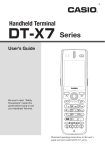
DT-X7 Series
Quick Start Guide
(Version 1.13)
CASIO Computer Co., Ltd.
Copyright ©2008. All rights reserved.
April 2008
Table of the Contents
Editorial Record
Preface
Chapter 1.
Chapter 2.
2.1
2.2
2.3
Chapter 3.
3.1
3.2
3.3
3.4
3.5
3.6
Chapter 4.
4.1
4.2
Chapter 5.
5.1
5.2
5.2.1
5.2.2
5.3
5.4
5.5
5.6
5.7
Chapter 6.
Chapter 7.
7.1
7.2
7.3
Chapter 8.
8.1
8.2
8.3
8.4
Chapter 9.
9.1
9.2
9.3
9.3.1
9.3.2
9.4
9.4.1
9.4.2
9.4.3
Chapter 10.
No part of this document may be produced or transmitted in any form or by any means, electronic
or mechanical, for any purpose, without the express written permission of CASIO Computer Co.,
Ltd. in Tokyo Japan. Information in this document is subject to change without advance notice.
CASIO Computer Co., Ltd. makes no representations or warranties with respect to the contents or
use of this manual and specifically disclaims any express or implied warranties of merchantability
or fitness for any particular purpose.
© 2008 CASIO Computer Co., Ltd. All rights reserved.
3
Preface
This guide clearly and concisely sets out the information developers need to know to get started with
the CASIO DT-X7 series development. The best methods of connecting to your development system
are covered and step by step instructions for installing and testing the CASIO SDKs are included.
The purpose of this guide is to get you to the point where you can start development; you should
refer to the library manuals for detailed information on the specific APIs.
Important Note
Since the DT-X7 does not have a touch panel display, it is not possible to click on a tab or icon on
the screen. However, you can change the focus using the F3 key (similar to Tab key on PC’s
keyboard) or the F2 key (similar to Shift+Tab keys on PC’s keyboard).
The Mouse Emulator preinstalled in the DT-X7 series can be invoked by pressing the Fn key and
then 4 key to make the mouse pointer appear in the center of the screen. It can be freely moved in
any direction on the screen you wish using one of the 1, 2, 3, 4, 6, 7, 8, and 9 numeric keys. The 5
key is the same as left-clicking the PC’s mouse. For details, see “Using the mouse cursor” on page
E-28 of DT-X7 Series User’s Guide.
In this reference manual, all explanations assume that the preinstalled Mouse Emulator is in the
invoked state.
5
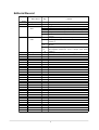
Editorial Record
Manua
l
Versio
1.01
1.10
1.11
1.12
1.13
Date edited
Pag
September
October
November
2007
eall
all
16
39
10
36
67
December
2007
12
14
April 2008
33
to
55
to
57
56
Content
Tentative version
Original version
Figures 3.1 and 3.2 in Chapter 3.4 are corrected.
An explanation about the Visual Studio 2005 is added.
The list of software required in Chapter 2.3 is updated.
Chapter 5.4 “ActiveSync Connection via Ethernet ” is
Chapter 11 “ Connecting via Windows Mobile Device
Center”
Chapter 3.1 “Application Development” is added.
Installing the cab file for Windows Mobile Device
Center is
Chapter 5.3 “ USB Connection via Windows Mobile
Device
In Chapter 8.3 “Using CASIO Libraries from C++”, a
development method for VCC++ Project with Visual
Studio is
In Chapter 8.3, the explanation on page 56 is updated.
4
1. Product Overview
The DT-X7 has been designed using the new concept of the Human-centered Design Processes and
is capable of performing a wide variety of powerful functions.
The following is a brief overview of the features available on the DT-X7 series handheld terminals.
For further detail on the hardware specifications, refer to DT-X7 Series Hardware Manual.
Outstanding development environment
Microsoft® Windows® CE 5.0 English Version as the built-in OS
Visual Studio 2005
Visual Studio .NET 2003 (Windows® CE .NET Utilities v 1.1 for Visual Studio .NET 2003)
eMbedded Visual C++ 4.0
Compatibility with various communication systems
Built-in ultra-small WLAN module compatible with the IEEE802.11b/g standard
High speed infrared communication with IrDA Ver. 1.3
Bluetooth® Version 2.0
Serial interface with USB version 1.1 (Host/Client)
Small size, light weight (improved portability)
Dimensions : Approx. 52.5 (W) x 166 (D) x 30.5 (H) mm
Weight
: Approx. 145 g
Improved durability
Impact resistance
Dust/Water-splash proof
Capable of scanning industrial standard bar code symbologies
Readable bar code symbologies:
UPC-A/E, EAN8, EAN13, Codabar, Code39, Code93, Code128/EAN128, ITF, MSI, Industrial
2of5, IATA, RSS-14, RSS Limited, RSS Expanded, RSS Stacked, RSS Expanded Stacked
CPU/Memory
High-performance CPU
Marvell® PXA270 Application Processor (runs at maximum 416 MHz)
Large-capacity memory
RAM
: 64MB (user area; approximately 40 MB)
F-ROM : 64MB (user area; approximately 30 MB)
* The drop durability height is a measured value resulting from actual testing. It does not necessarily guarantee the
product from damage.
6
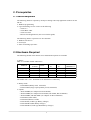
2. Prerequisites
2.1 Skills Required
The following skills are required by developers aiming to develop application software for the
DT-X7.
Windows programming
A good knowledge of one or more of the following
- Visual C++
- Visual Basic .NET
- Visual C# .NET
- Browser based applications (not covered in this guide)
The following skills or experience are also desirable.
Windows CE devices
ActiveSync
Some networking experience
2.2 Hardware Required
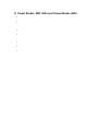
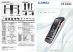
The following models of the DT-X7 series and dedicated options are available.
DT-X7
Table 2.1 Available models and features
Model no.
Laser
Scanner
No
Yes
Yes
Yes
Yes
Bluetoo
Linear
Bluetoo
th
th
Imager
DT-X7M10U
Yes
Yes
No
DT-X7M10E
No
No
Yes
DT-X7M10R
No
No
Yes
DT-X7M10ENo
No
Yes
DT-X7M10RNo
No
Yes
CN
Note:
The model with “-CN” denotation is for destination of China only.
WLAN
(IEEE802.11
b/g) No
No
Yes
No
Yes
Battery Packs
- HA-F20BAT (Battery Pack, 1100 mAh)
- HA-F21LBAT (Large-capacity Battery Pack, 1880 mAh)
Options
- AD-S15050BE (AC Adaptor for HA-F30CHG)
- AD-S42120BE (AC Adaptor for HA-F60IO, HA-F62IO, HA-F32DCHG)
- AD-S60160BE, AD-S60160BU (AC Adaptor for HA-F36DCHG)
- HA-F60IO (USB Cradle)
- HA-F62IO (Ethernet Cradle)
- HA-F30CHG (Cradle-type Battery Charger)
- HA-F32DCHG (Dual Battery Charger)
- HA-F36DCHG (Cradle-type Dual Battery Charger)
7
- DT-380USB (USB cable)
- HA-F95HB (Hand Belt)
Note:
“-CN” attached at the end of model number denotes that the model is dedicated for the final
destination of China. A note about compliance with the Chinese “RoHS” requirement promulgated
by the Ministerial Decree No. 39 is included in the carton box; the RoHS compliant seal is affixed
on the body and the seal of the packing material recycle marking is affixed on the carton box.
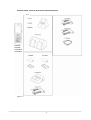
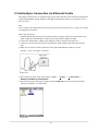
See the following page for external views of the DT-X7 and the dedicated options.
8
External views of the DT-X7 and the dedicated options
Option
DT-X7M10E
DT-X7M10R
DT-X7M10E-CN
DT-X7M10R-CN
Figure 2.1
9
2.3 Software Required
The following software tools and libraries are required in order to develop software for the DT-X7.
Please ensure that you download or purchase the correct Microsoft tools as appropriate.
C / C++
Download for free from;
http://www.microsoft.com/downloads/details.aspx?familyid=46F72DF1-E46A-4A5F-A791-0
9F07AAA1914&displaylang=en
Visual Basic / Visual C#
Microsoft Visual Studio 2005 (not free of charge)
Microsoft Visual Studio .NET 2003 (not free of charge)
Windows CE Utilities for Visual Studio .NET 2003 Add-on Pack 1.1
From Microsoft web site, see
http://www.microsoft.com/downloads/details.aspx?familyid=7ec99ca6-2095-4086-b0cc-7c6c
39b28762&displaylang=en
Microsoft ActiveSync 4.2 (or later)
Download for free from;
http://www.microsoft.com/downloads/details.aspx?FamilyID=7269173a-28bf-4cac-a682-58d
3233efb4c&DisplayLang=en
Microsoft Windows Mobile Device Center 6.1 (for Windows Vista)
Download for free from;
http://www.microsoft.com/downloads/details.aspx?familyid=46F72DF1-E46A-4A5F-A791-0
9F07AAA1914&displaylang=en
10
CASIO DT-X7 SDK
Download the DT-X7 SDK from
http://www2.casio.co.jp/system_en/pa/PADealer/
(The site requires your user name and password. Enter your user name and password as issued
by CASIO.)
DT-X7_SDK.msi
- en_DevEmu500.msi
- en_MoDev.msi
- en_Flink.msi
- en_JPEG.msi
- en_MoDevSamle.msi
- en_FlinkSample.msi
- en_JPEGSample.msi
11
3. Setting Up the Development Environment
3.1 Application Development
This chapter explains about what you need to set up for the development environment before
starting your application development.
1.
2.
3.
4.
5.
with the
development platform can be started. After application is developed, transfer it to the Device
Emulator or an actual terminal of the DT-X7 via ActiveSync or Windows Mobile Device
Center for check on the operability. For application development method and transferring your
application, refer to “eMbedded Visual C++”, ”Visual Studio .NET 2003 and Visual Studio
2005”.
12
3.2 Installing CASIO SDK Files
Download the CASIO DT-X7 SDK files from the following site and execute each “msi” file listed in
Table 3.1 ;
http://www2.casio.co.jp/system_en/pa/PADealer/
(The site requires your user name and password. Enter your user name and password as issued by
CASIO.)
Table 3.1
CASIO SDK File
DT-X7_SDK.msi
Description
DT-X7 Export SDK
en_DevEmu500.msi
DT-X7 Emulator
en_MoDev.msi
en_Flink.msi
en_JPEG.msi
en_MoDevSample.
msi
Common Device Control Library
FLINK Library
JPEG Library
Common Device Control Library
sample program
en_FlinkSample.ms
i
FLINK Library sample program
en_JPEGSample.ms
i
JPEG Library sample program
13
Default folder path
C:\Program Files\Windows CE
Tools\wce500\DT-X7
C:\Program Files\Common
Files\CASIO\Emulator
C:\Program Files\CASIO\MBSys
C:\Program Files\CASIO\MBSys
C:\Program Files\CASIO\MBSys
C:\Documents and Settings\All
Users\Application
Data\CASIO\Samples
C:\Documents and Settings\All
Users\Application
Data\CASIO\Samples
C:\Documents and Settings\All
Users\Application
Data\CASIO\Samples
3.3 Installing CAB Files
1.
2.
3.
4.
5.
Library
Common Device Control library (see
note) library
JPEG
FLINK library
CAB file
en_MoDev.ARMV4I.CAB
enJPEG.ARMV4I.CAB
en_Flink.ARMV4I.CAB
14
CAB file
USBClientDTX7.110.CAB
Description
USB client supported by Windows Mobile Device
Center
3.4 eMbedded Visual C++ 4.0
ExportSDK for DT-X7 is required to develop application software with eMbedded Visual C++ 4.0
(see note 1). Follow the steps below to install it.
1. Double click the DT-X7_SDK.msi (see note 2) file and follow the prompts that appear on the
screen to install the SDK.
2. When prompted whether you want to install Custom or Complete installation, choose
Complete.
3. When the installation is finished, start up eMbedded Visual C++ 4.0.
4. Go to Chapter 7 “eMbedded Visual C++” and follow the instructions to verify that the SDK has
been installed correctly.
If eMbedded Visual C++ has been installed in your PC already, you will notice that you now have a
new SDK and, once you select that new SDK, a new target device (DT-X7) in the comb-box menu
in the toolbar. Also, if you use any of the Remote Tools in eVC++ then you will find DT-X7 is
listed as a new target (for example, try the Remote Registry Editor).
For more details, refer to Chapter 7 “eMbedded Visual C++”.
Notes:
1. If eMbedded Visual C++ 4.0 is used to develop application software, be sure to install Service
Pack 4 prior to the development.
2. Other SDKs (e.g. standard SDK etc.) released before the ExportSDK are also operable.
3. Application software developed using MFC (Microsoft Foundation Class) for CASIO IT-10 is
not operable on the DT-X7.
4. Any application developed not using MFC is operable on the DT-X7.
15
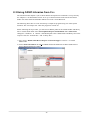
3.5 Visual Studio 2005
Install each ‘msi’ package as described in Table 3.1. This will install all the necessary SDK and
library files on your PC. See Chapter 8. for basic usage instructions for the SDK. Follow the steps in
Chapter 5 “Connecting the DT-X7 to the PC” before checking the steps below to confirm that you
can connect to the DT-X7 from Visual Studio 2005.
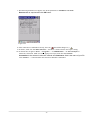
1. Establish connection with the DT-X7 via ActiveSync.
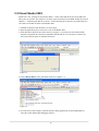
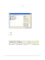
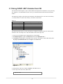
2. Open the application project for VB or C# in Visual Studio 2005.
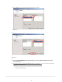
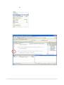
3. Click the button shown in the red box below (see Figure 3.1) to make sure that Visual Studio
2005 has recognized the connection established with the DT-X7 via ActiveSync. If it does not,
start up ActiveSync again to establish connection.
Figure 3.1
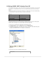
4. Choose DT-X7 Device in the pull-down menu box in Figure 3.2.
Figure 3.2
5. You will now be able to deploy solutions and also debug applications on the attached DT-X7
using the Visual Studio 2005 debugging features.
16
3.6 Visual Studio .NET 2003
Install each ‘msi’ package as described in Table 3.1. This will install all the necessary SDK and
library files on your PC. See Chapter 8. for basic usage instructions for the SDK. Follow the steps in
Chapter 5 “Connecting the DT-X7 to the PC” before checking the steps below to confirm that you
can connect to the DT-X7 from Visual Studio .NET 2003. Microsoft has released an add-on for
Visual Studio .NET 2003 that allows you to set the target CPU for a connected device (Visual
Studio is unable to detect the target CPU of non-Pocket PC devices).
Follow the steps below to install the add-on pack.
1. Download “Windows CE Utilities for Visual Studio .NET 2003 Add-on Pack 1.1” from the site
described in Chapter 2.3 “Software Required”.
2. Establish connection via ActiveSync between the DT-X7 and PC using any of the methods
described in this guide.
3. Navigate to Tools → Select Windows CE Device CPU.
-
You will now, for example, be able to choose Deploy <appname> from the Build menu and your
project will be directly deployed to the DT-X7. You will now also be able to remotely debug
applications over your ActiveSync connection.
17
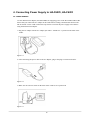
4. Connecting Power Supply to HA-F60IO, HA-F62IO
4.1 HA-F60IO
Use the dedicated AC adaptor (AD-S42120BE) for supplying power to the HA-F60IO USB Cradle.
Ensure that you connect the AC adaptor to the cradle before starting communication between the
DT-X7 and PC via the cradle. Follow the steps below to connect the power supply to the DT-X7
using the dedicated AC adaptor.
1. Plug the AC adaptor into the AC adaptor jack where “DCIN12V” is printed on the back of the
cradle.
Figure 4.1
2. After connecting the power cable to the AC adaptor, plug in the plug to an electrical outlet.
Figure 4.2
3. Make sure the selector switch on the back of the cradle is set to position B.
Figure 4.3
18
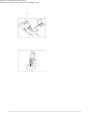
4. Connect a USB cable (DT-380USB) to the USB client port on the back of the cradle, and then
connect the other end of the cable to the PC. USB host port is used when connecting the cradle
with other USB peripheral devices.
Figure 4.4
5. Align the USB cradle mount holes on the back of the DT-X7 with the mount hooks on the cradle
after aligning the contacts on the bottom of the DT-X7 with the power contacts of the cradle. The
power LED on the front of the cradle will light green if the DT-X7 has been properly mounted.
Figure 4.5
Status of Indicator 1 on DT-X7
Orange
Red
Green
Important notes:
lights green. Charging the battery pack or
communication will not proceed if it is not mounted properly.
19
4.2 HA-F62IO
Use the dedicated AC adaptor (AD-S42120BE) for supplying power to the HA-F62IO Ethernet
Cradle. Ensure that you connect the AC adaptor to the cradle before starting communication
between the DT-X7 and PC via the cradle. Follow the steps below to connect the power supply to
the DT-X7 using the dedicated AC adaptor.
1. Plug the AC adaptor into the AC adaptor jack on the back of the Ethernet Cradle.
Figure 4.6
2. After connecting the AC adaptor to the power cable, plug in the plug of the power cable to an
electrical outlet.
Figure 4.7
3. Set the selector switch on the back of the Ethernet cradle to the port that will be used. Set the
switch to “LAN” to use the LAN port or to “USB” to use the USB port.
Figure 4.8
20
4. Before using the cradle ports, remove the caps from the ports. When using a LAN, connect one
end of the LAN cable to the LAN port and the other end to the PC or hub. When using a USB
connection, connect one end of the USB cable (DT-380USB) to the USB port and the other end
to the PC.
Figure 4.9
5. Align the contacts on the underside of the DT-X7 with the power supply contacts on the Ethernet
Cradle and then set the DT-X7 into the cradle so that mount holes in the back of the DT-X7 are
aligned with the mount hooks on the cradle. Once the DT-X7 is properly set in the cradle, the
power LED on the front of the Ethernet cradle lights green.
Figure 4.10
Status of Indicator 1 on DT-X7
Orange
Red
Green
Important notes:
lights green. Charging battery pack or communication
will not proceed if it is not mounted properly.
The LAN and USB connections cannot be used concurrently.
Always cap ports that are not being used. Using the Ethernet Cradle while the ports are
uncapped can cause damage.
21
5. Connecting the DT-X7 to PC
To make connection establishment with PC, use one of the methods, depending on the OS your PC
runs, described below.
22
5.1 ActiveSync Connection
In nearly all cases during development work you will be communicating with the DT-X7 via an
ActiveSync connection. There are many ways to connect the DT-X7 to a PC via ActiveSync.
5.2 ActiveSync Connection via USB
If you have already installed ActiveSync and connected the DT-X7 to the PC via direct USB, You
may skip Chapter 5.2.1. You already have the USB driver and ActiveSync in your development
environment. If you do not yet have the cradle driver on your PC, .download the USB driver files
“wceusbsh.inf” and “wceusbsh.sys” from the CASIO Web Site and copy them to an appropriate
folder.
23
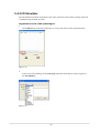
5.2.1 Installing ActiveSync for the First Time
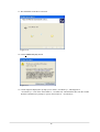
1. Install ActiveSync first. Run the ActiveSync ‘msi’ file.
Figure 5.1
2. Click Install button.
Figure 5.2
24
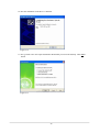
3. Pause the installation when the menu in Figure 5.3 is displayed; you have to install the driver at
this point.
Figure 5.3
4. Connect the USB cable to the PC and the other end to the USB Cradle and also the AC adaptor to
the USB Cradle.
5. Put the DT-X7 on the cradle and confirm that the green LED on the front of the cradle is lit. If not,
be sure the DT-X7 is positioned firmly on the cradle.
6. When the DT-X7 is mounted on the USB Cradle, a dialog is displayed to prompt you to install
the suitable driver. If you have not yet obtained the driver files, see page 23 for details of what
you need to download.
7. Choose No, not this time radio button in Figure 5.4 and then click Next> button.
Figure 5.4
25
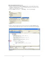
8. Then, choose Install from a list or specific location [Advanced] radio button in the menu.
Figure 5.5
9. Click Next > button.
Figure 5.6
26
10. Choose Windows CE USB Devices icon.
Figure 5.7
11. Click Have Disk… button.
Figure 5.8
12. Click Browse… button. Select “wceusbsh.inf” from the folder you created in step 6.
Figure 5.9
27
13. The installation of the driver will start.
Figure 5.10
14. Click Continue Anyway button.
Figure 5.11
15. A menu might be displayed to prompt you to install “wceusbsh.sys”. This happens if
“wceusbsh.sys” is not in the same folder as “wceusbsh.inf”. Download this file from the CASIO
Web Site and follow the prompts to specify the location of “wceusbsh.sys”.
28
16. Now the installation of the driver is finished.
Figure 5.12
17. Now go back to the ActiveSync Installation Wizard that you left on the desktop. Click Next >
button.
Figure 5.13
29
18. Now the connection is established. You can select either partnership option according to your
needs. Then click Next > button.
Figure 5.14
19. Now the connection is completed. You can start up eMbedded VC++ or Visual Studio and create
a program and deploy it to the DT-X7.
Figure 5.15
Notes:
cause disconnection of communication.
30
5.2.2 If ActiveSync Is Already Installed
This is the procedure if ActiveSync is already installed on the PC. You just need to let the PC
recognize the DT-X7 and install the cradle driver as in steps 6 to 16 in Chapter 5.2.1.
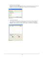
1. Select File → Connection Settings…. from the menu in ActiveSync. See Figure 5.16.
Figure 5.16
2. Check Allow USB connection with this desktop computer. USB is available.
Figure 5.17
31
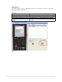
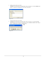
3. On the DT-X7, in Control Panel, select the PC Connection option. Confirm that PC
Connection is set to “USB Default”. If not, select ‘USB Default’ and tap OK button.
Figure 5.18
4. When the DT-X7 is mounted on the USB Cradle, a menu to prompt to install the driver is
displayed. Follow the same steps in Chapter 5.2.1.
Figure 5.19
32
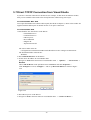
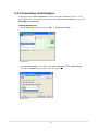
5.3 USB Connection via Windows Mobile Device Center
To establish connection via USB interface with PC runs in Windows Vista, use Windows Mobile
Device Center (“WMDC”). The DT-X7 with the factory-setting (default) does not support the
WMDC. Follow the procedure below to change the setting on the DT-X7.
Note:
Note that the CAB file, USBClientDTX7E.110.CAB, must be installed in the DT-X7 prior to
establishing connection with the DT-X7 via Windows Mobile Device Center. For installation
method, refer to Chapter 3.3 “Installing CAB Files”.
Procedure
1.
2.
3.
Figure 5.20
4.
Figure 5.21
5.
Figure 5.22
33
6.
7.
The DT-X7 starts up again.
Mount the DT-X7 on the cradle, and then follow a message appeared in the WMDC on the PC.
Notes:
To resume the factory default setting, choose ActiveSync/LMWIN radio button in Step 3 on
the previous page, and start up the DT-X7 again.
The WMDC version 6.1 or later will support the connection establishment via USB interface.
Any other versions of the WMDC earlier are not interoperable with Windows CE devices.
34
5.4 ActiveSync Connection via IrDA
If the PC has an IrDA interface, it is possible to connect the DT-X7 to the PC via IrDA using
ActiveSync.
Follow the steps below:
1. Choose PC Connection in the Control Panel on the DT-X7.
2. Set PC Connection to IrDA.
3. Set the COM port used by ActiveSync on the PC to Infrared Port(IR).
4. Place the IrDA port located on the bottom of the DT-X7 facing the IrDA port on the PC.
Communication can be established if the distance is between zero and approximately 1 m. In
the case of 4Mbps rate, the maximum distance is approximately 30 cm.
5. On the DT-X7, from Start menu, navigate to Programs → Communication →
ActiveSync to start up ActiveSync.
35
5.5 ActiveSync Connection via Ethernet Cradle
This chapter describes how to establish a high speed LAN connection on the WLAN non-integrated
models (DT-X7M10E and DT-X7M10U) with HA-F62IO Ethernet cradle via ActiveSync 3.8 (see
note) or earlier.
Note:
Later versions of the Microsoft ActiveSync do not support this connection. Use version 3.8 or earlier
to establish the connection.
Follow the steps below:
1. Establish partnership first between the DT-X7 and PC using any method so far described in this
guide (connection establishment via either IrDA, USB cradle or Ethernet cradle).
2. Connect the dedicated AC adapter to the Ethernet cradle as described in Chapter 4.2 .
3. Connect one end of the network cable to the Ethernet cradle and the other end to the network
hub.
4. Make sure the selector switch on the back of the HA-F62IO Ethernet cradle is set to the
position ”LAN”. See Figure 5.23 below.
Set to LAN
Figure 5.23
5. Place the DT-X7 in the cradle and navigate to Start → Settings → Control Panel →
Network and Dial-up Connections.
6. The following screen will appear. Double click the AX887721 icon. The icon will not appear
unless the terminal is set in the cradle.
Figure 5.24
36
7. The following TCP/IP screen appears. Set all the parameters in IP Address and Name
Servers tabs as required and click OK button.
Figure 5.25
8. If the connection is established correctly, the icon ( ) in the taskbar changes to ( ).
9. On the PC, make sure that Allow network… checkbox is checked in the ActiveSync setting.
10. On the DT-X7, navigate to Start → Programs → Communication → LAN ActiveSync to
initiate the connection. Make sure in the popup ActiveSync menu box that Network
Connection is the selected connection method and Connect to: field is the name of your PC.
Click Connect … button and then the connection should be established.
37
5.6 Accessing Shared Network Drive on Your LAN
Assuming you have a valid network connection established, you can access shared drives on your
PC from the File Explorer on the DT-X7. The following shows the steps to initiate this.
1.
2.
3.
4.
5.
38
5.7 Direct TCP/IP Connection from Visual Studio
If you have a network connection to the DT-X7 (for example, via WLAN or the Ethernet cradle)
then you can establish a direct link to the development PC without using ActiveSync.
For Visual Studio .NET 2003
You require the WindowsCE Utilities add-on pack (described in Chapter 3). Refer to the readme file
supplied with the add-on pack for details on how to set up the connection.
For Visual Studio 2005
1. Download the files listed below to the DT-X7.
- Clientshutdown.exe
- ConmanClient2.exe
- CMAccept.exe
- DeviceDMA.dll
- eDbgTL.dll
- TcpConnectionA.dll
The source folder in the PC:
C:\Program Files\Common Files\Microsoft Shared\CoreCon\1.0\Target\wce400\armv4i
The destination folder in the DT-X7:
\Windows
2. Run ConmanClient2.exe on the DT-X7.
3. Set the device IP address in Visual Studio 2005.
Navigate to Tools in the main menu of Visual Studio 2005 → Options… → Device Tools →
Devices.
Choose DT-X7 Device in the pull-down menu of Devices: and click Properties….
Click Transport: to access Configure… and set up Device IP address as shown in Figure
5.26.
Figure 5.26
4. Run CMAccept.exe on the DT-X7.
5. Navigate to Tools in the main menu of Visual Studio 2005 → Connect to Device….
39
6. Select DT-X7 Device in the list of Devices: and click Connect button. The screen in Figure
5.27 if appear indicates the success of connection establishment.
Figure 5.27
40
6. Configuring WLAN on the DT-X7
To establish communication between the DT-X7 (DT-X7M10R) and PC via WLAN configuration,
follow the steps, 1 to 6, below to set up a WLAN configuration on the DT-X7. After setting up the
configuration, be sure to perform a site survey prior to starting communication via WLAN.
1. Navigate to Start → Settings → WLANConfig and then click IP tab.
Figure 6.1
Table 6.1
Parameter
Enable DHCP or Configure
IP
MASK
GateWay
DNS1
DNS2
WINS1
WINS2
Description
Determines “Enable” or “Disable” for DHCP.
Determines IP address.
Determines subnet mask.
Determines default gateway.
Determines primary DNS address.
Determines secondary DNS address.
Determines primary WINS address.
Determines secondary WINS address.
If any of the settings in Figure 6.1 is omitted, the process described in the following table will
automatically take place in the field.
Table 6.2
Parameter
Enable DHCP or
Configure IP
IP
MASK
GateWay
DNS1
DNS2
WINS1
WINS2
Nothing is set (DHCP)
”Enable DHCP” is assumed.
”Configure IP” is set
”Configure IP” is set.
Does not determine IP address.
Does not determine subnet mask.
Does not determine gateway.
Does not determine primary DNS
address.
Does not determine secondary DNS
address.
Does not determine primary WINS
address.
Does not determine secondary WINS
address.
Entered address is set as is.
Entered address is set as is.
Entered address is set as is.
Entered address is set as is.
41
Entered address is set as is.
Entered address is set as is.
Entered address is set as is.
2. Click Basic tab. Set each parameter in the tab by referring to the descriptions for the parameters
in Tables 6.3 and 6.4
Figure 6.2
Table 6.3
Parameter
SSID
Securit
Disab
y
WEP
WPA
Key
Description
Enter the SSID of the network you want to connect to.
None.
Open in Authentication field.
PSK in Authentication field (if selected, the Key field must be set
also.)
EAP-PEAP in Authentication field
EAP-TLS
in Authentication
field digits (13 hex pairs) in the Key field if
Enter
26 (maximum)
alphanumeric
128 bit
radio button is selected. Or, enter 10 (maximum) alphanumeric digits (5 hex pairs)
in
the Key field if 64 bit radio button is selected.
The field displays the number of characters that have been entered.
***** in the field implies that the key has been extracted from the ini file. If *****
in
If EAP-PEAP radio button in Authentication field is selected, click the EAP-Properties button
that appears when selecting the EAP-PEAP radio button to set also the following parameters.
Table 6.4
Parameters in
Description
Default
EAP-Properties
User name
Input a user name in alphanumeric None
(maximum 100
Password
Input a password in alphanumeric (maximum None
100
alphanumeric).
***** in the field implies that the password has
Domain
Validate server
certificate
been
extracted from the ini file. If ***** in the
Input a domain in alphanumeric (maximum
100
Set up the requisition for server certificate.
With check mark : certificate is required.
Without check mark: certificate is not
required.
42
None
Certificate
necessary
is
not
If EAP-TLS radio button in Authentication field is selected, click the EAP-Properties button that
appears when selecting the EAP-TLS radio button to set the following settings.
Table 6.5
Parameters in
EAP-Properties
User name
Certificate
Description
Input a user name in alphanumeric
(maximum
Select a client certificate installed
already
(maximum 100 alphanumeric).
Default
None
None
Search button in the field will display a
Domain
Validate server
certificate
list
of in alphanumeric (maximum 100
Input
alphanumeric)
Set up the requisition for server
certificate.
With check mark : certificate is
required.
Without check mark : certificate is not
None
Certificate is required.
3. Click WLAN tab.
Figure 6.3
Table 6.6
Field / Radio
Buttons
Adapter power
Power save
Standard
RSSI Level for
initiating
roaming
Description
On
Off
Enable
Disable
b
b/g
No
roaming
Default
High
Enable power to the integrated WLAN module.
Disable power to the integrated WLAN module.
Enable power save mode for the WLAN
Disable power save mode for the WLAN
Set up IEEE802.11b standard effect.
Set up IEEE802.11b/g standard effect.
Set up “ -100 dBm ” for roaming starting threshold
level,
a level where communication via WLAN is
practically
Set
up “ -78 dBm ” for the roaming starting
threshold
Set up “-72 dBm” for roaming starting threshold
level,
for faster (more frequent) roaming
43
Defaul
t Yes
Yes
Yes
Yes
4. Click Detail Tab.
Figure 6.4
Table 6.7
Field / Radio Buttons
WLAN configure
WLANConfig
/
/
Status
display
NetSearch
tool
WLANConfig
/
NetUI
NetUI / NetUI
Description
- Use only CASIO provided WLAN tool.
- Configure WLAN setting with settings
extracted from the ini file.
- Initiate NetSearch when tapping the icon
in
- Use both CASIO provided WLAN tool
and
MS tool.
- Configure WLAN setting with settings
extracted from the ini file.
- Initiate NetUI (MS tool) when tapping
-the
Use only the MS tool.
- Configure WLAN setting, not with
settings
extracted from the ini file.
- Initiate NetUI when tapping the icon in
the
task tray.
Default
Yes
If this radio button is selected and the OK
Enable adhoc network setting
Enable all authentication settings
Inifile comment
button
With check mark : enable the setting.
Without check mark : disable the setting.
With check mark : enable the setting.
Without check mark : disable the setting.
Enter a comment of up to 100 characters
to be
written in the ini file.
44
Yes
Yes
None
5. If OK button in the popup warning message (see Table 6.7 for description of NetUI/NetUI radio
button) is clicked, the screen in Figure 6.5 appears. Click OK button to perform a reset on the
terminal so that the setting becomes effective.
Figure 6.5
6. Check to make sure that the connection has been established using the NetSearch utility, and
then navigating to the Ping function in there. Enter HostName first and then click Ping to check
that you are connected to the network correctly.
45
7. eMbedded Visual C++
7.1 Building a Simple eVC++ 4.0 Test Program
1. On the PC, initiate eVC++ 4.0.
2. Navigate to File → New in the File menu.
Figure 7.1
3.
4.
5.
6.
7.
then click OK button.
8. Below the toolbar you will see a line of pull-down menu lists. Look for the one that indicates the
target devices available to you and select DT-X7 in the list. The right most pull-down menu
list will change to DT-X7 Device.
Figure 7.2
9. Initiate an ActiveSync connection using one of the methods described in this guide.
10. Select Rebuild All from Build menu (or use the appropriate icon on the toolbar).
46
11. The program will be built and automatically downloaded to the DT-X7. By default, the program
will be copied to the root folder on the terminal. Run the program to check that the process was
successful. Note that for this basic example you will need to use the mouse emulator to close the
application on the device.
You are now ready to begin development work with the DT-X7. The full operation of eVC++ 4.0
and the use of features such as remote debugging are beyond the scope of this guide. See the
Chapter 10 “Resources” for details on where to start if you are new to eMbedded Visual C++
development.
47
7.2 Using CASIO Libraries from eVC++ 4.0
The following libraries (“Common Device Control Library”) are provided for C++ developers.
Table 7.1
Library
System Library
Scanner Library
Bluetooth
Camera Library
Printer Library
Imager Library
Dynamic
Link
SystemLib.dll
OBReadLib.dll
BluetoothLib.dll
CameraLib.dll
PrinterLib.dll
ImagerLib.dll
Import Library
SystemLib.lib
OBReadLib.lib
BluetoothLib.lib
CameraLib.lib
PrinterLib.lib
ImagerLib.lib
Header File
SystemLib.h
OBReadLib.h
BluetoothLib.h
CameraLib.h
PrinterLib.h
ImagerLib.h
Each library in the table consists of a header file, a dll and a library file. The dlls are built into the
ROM of the DT-X7 and you do not need to download them. The following is a simple example
using one of the System Library functions in the simplest kind of WindowsCE program. The screen
will flip 180° each time this program is executed.
1. Make sure all the ” .h” files for the CASIO libraries are installed in C:\Program
Files\CASIO\MBSys\INCLUDE (This is the default installation location but yours will be
different if you installed the SDK to another location).
2. Make sure all the “.lib” files for the CASIO libraries have been installed in C:\Program
Files\CASIO\MBSys\LIB\ARMV4I
3. In eVC++ 4.0, select New from the File menu.
4. Highlight WCE Application. Choose a location and a name for the project and make sure the
ARMV4I option is checked. Click Next > button.
5. On the next dialog click A simple Windows CE application option. Click Finish and then
click OK button.
6. Make sure the DT-X7 is the selected SDK and target device in the pull-down list boxes.
7. Click ClassView tab in Solution Explorer and expand classes fully until you can see
WinMain() class. Double click it.
8. At the top of the source file, under #include stdafx.h code add the following code.
#include <SystemLib.h>
#include <SystemLibdef.h>
48
9. Move to the line // TO DO: Place code here and add the following code.
int
result = SysGet180Rotate();
if( result == FALSE )
{
SysSet180Rotate( TRUE );
}
else
{
SysSet180Rotate( FALSE );
}
10. On the Project menu, navigate Add To Project → Files…
11. Change Files of type: pull-down menu list to Library files (.lib).
12. Navigate to the folder where the CASIO library files are stored (see step no. 2 in the previous
page), highlight SystemLib file and click OK button.
13. Initiate ActiveSync to establish connection between the DT-X7 and the PC.
14. Select Build All from Build menu. The project will be built and copied to the DT-X7.
15. Check the operation by running the program. You should find that each time the program is
executed, the screen flips 180°.
You should now be able to use the CASIO System library in your C++ applications. See the
Common Device Control Library Manual for full details of all the functions. You may also like to
try some of the sample programs provided by CASIO (see next section).
49
7.3 Sample Program
The following sample programs are included in the DT-X7 Export SDK.
Table 7.2
Notes:
50
Name
BluetoothLibSample
CameraLibSample
IMGLibSample
IMGLibSample2
JpegSample
OBRLibSample
PrnLibSample
SystemLibSample
FlinkLibSample
Description
Connects to a Bluetooth printer and prints out data.
Takes pictures and displays them on the screen.
Scan barcodes using the imager with settings set by Imager setting file.
Program of IMGDemo.exe
Displays Jpeg files
Reads a barcode using the Laser library
Prints out data on the built-in printer
Demonstrates LED and buzzer functions
Demonstrate Infrared communication between two terminals using
Flink protocol.
8. Visual Studio .NET 2003 and Visual Studio 2005
modifications, the solution/project from Visual
Studio .NET 2003 is automatically upgraded by Visual Studio 2005. This may result in different
configuration of the output folder according to the parameter settings for the project file. Please
take care when using Visual Studio 2005 to upgrade an existing application and always keep a
backup of your existing project.
51
8.1 Using CASIO .NET Libraries from VB
The intention of this chapter is just to check that the development environment is set up correctly.
See Chapter 3.5 for information on how to set up a connection between the DT-X7 and Visual
Studio.
The following wrapper class library files that allow VB applications to access the Casio library
(“Common Device Control Class Library”) functions are provided.
Table 8.1
Library
System Library
Scanner Library
Bluetooth Library
Camera Library
Printer Library
Dynamic Link Library
SystemLibNet.dll
OBReadLibNet.dll
BluetoothLibNet.dll
CameraLibNet.dll
PrinterLibNet.dll
The following shows how to create and start up a simple test program using one of the System
functions. The screen flips 180° when the button on the form is pressed.
1. Create a new VB Smart Device Application in Visual Studio.
2. In Solution Explorer, right-click References and click Add Reference…
3. Click Browse and navigate to the folder where you have stored the CASIO .NET library files.
Highlight SystemLibNet.dll and click Open. Click OK button.
Figure 8.1
4. Add a button to the form, rename it Rotate, and double click it.
5. At the top of the source file, add the line:
Imports Calib
52
6. In the event function for the button click, add the following code.
If (SystemLibNet.Api.SysGet180Rotate() = 0 ) Then
SystemLibNet.Api.SysSet180Rotate(True)
Else
SystemLibNet.Api.SysSet180Rotate(False)
End If
Note:
If you type this code manually you should see the IntelliSense offer you suitable options as
appropriate. If you do not, make sure you review steps 1 to 5 to make sure you have added the
reference correctly.
7. Initiate ActiveSync to establish connection between the DT-X7 and PC.
8. Select Deploy <name of project> on Build menu.
9. The project will be built and copied to the DT-X7. By default, it will be copied to \Program
Files\<name of project> folder. SystemLibNet.dll will be deployed to the same folder.
10. Check that the program works correctly on the DT-X7.
You can also use the CASIO samples as described in Chapter 7.3.
53
8.2 Using CASIO .NET Libraries from C#
The intention of this chapter is just to check that the development environment is set up correctly.
See Chapter 3.5 for information on how to set up a connection between the DT-X7 and Visual
Studio.
The following wrapper class library files that allow C# applications to access the CASIO library
(“Common Device Control Class Library”) functions are provided.
Table 8.2
Library
System Library
Scanner Library
Bluetooth Library
Camera Library
Printer Library
Dynamic Link Library
SystemLibNet.dll
OBReadLibNet.dll
BluetoothLibNet.dll
CameraLibNet.dll
PrinterLibNet.dll
The following shows how to create and start up a simple test program using one of the System
functions. The screen flips 180° when the button on the form is pressed.
1. Create a new C# Smart Device Application in Visual Studio .NET.
2. In Solution Explorer, right click References and click Add Reference…
3. Click Browse and navigate to the folder where you have stored the CASIO .NET library files.
Highlight SystemLibNet.dll and click Open. Click OK button.
Figure 8.2
4. At the top of your source file add the following code.
using Calib;
54
5. Add a button to your form, double click it and add the following code:
if( SystemLibNet.Api.SysGet180Rotate() == 0 )
SystemLibNet.Api.SysSet180Rotate(true);
else
SystemLibNet.Api.SysSet180Rotate(false);
Note:
If you add this code manually you should see the IntelliSense offer you suitable options as
appropriate. If you do not see this, then review steps 2 to 4 in the previous page to make sure you
have not made a mistake.
6. Initiate ActiveSync to establish connection between the DT-X7 and PC.
7. Select Deploy <name of project> on Build menu.
8. The project will be built and copied to the DT-X7. By default, it will be copied to \Program
Files\<name of project> folder. SystemLibNet.dll will be deployed to the same folder.
9. Check that the program works correctly on the device.
You can also use the CASIO samples as described in Chapter 7.3.
55
8.3 Using CASIO Libraries from C++
The intention of this chapter is just to check that the development environment is set up correctly.
See Chapter 3.5 for information on how to set up a connection between the DT-X7 and Visual
Studio. You must install Visual Studio 2005 Service Pack 1 from Microsoft.
The following shows how to create and start up a simple test program using one of the System
functions. The screen flips 180° when the program is carried out.
Before following the steps below, you will need to add the paths for the CASIO header and library
files to Visual Studio 2005. Select Tools-Options-Projects and Solutions-VC++ Directories.
Change the “Platform” to “DT-X7” and add the path to the CASIO header and library files to the
respective lists for “Include files” and “Library files”.
1. First, create a Win32 Smart Device Project called DeviceApp for Visual C++ in Visual
Studio 2005.
2. Choose Pocket PC 2003 in the Selected SDKs field in the Platforms of Win32 Smart Device
Project Wizard and click < button.
Figure 8.3
56
3. Choose DT-X7 in the Installed SDKs field and click > button.
Figure 8.4
4.
Figure 8.5
5. Choose Console Application for the Application type in the Application Settings menu, and
click Finish button.
6. In Solution Explorer, click DeviceApp.cpp and then append the source code below subsequent
to “#include <commctrl.h>”.
#include <SystemLib.h>
57
7. Append the source code below in the main function of DeviceApp.cpp.
int result;
result = SysGet180Rotate();
if( result == FALSE ){
result = SysSet180Rotate( TRUE );
}
else{
result = SysSet180Rotate( FALSE );
}
8. Choose Properties in the Project of Visual Studio 2005, and navigate to Configuration
Properties → Linker → Input → Additional Dependencies and then append
SystemLib.lib (see red circle).
Figure 8.6
9. Choose DT-X7 Device for the Target Device to establish connection with the PC.
10. Choose Debug in Visual Studio 2005 and then click either Start Debugging or Start
Without Debugging.
11. The project will be built and copied to the “\Program Files\<name of project>” folder (by default)
in the DT-X7.
12. Check that the program runs correctly on the DT-X7.
58
8.4 Sample Program
The following sample programs are included in the DT-X7 Export SDK.
Table 8.3
Notes:
Program
BluetoothLibSampl
CameraLibSample
IMGLibSample
IMGLibSample2
JpegSample59
OBRLibSample
PrnLibSample
SystemLibSample
FlinkLibSample
Description
Connects to a Bluetooth printer and prints out data.
Takes pictures and displays them on the screen.
Scan barcodes using the imager with settings set by Imager setting file.
Program of IMGDemo.exe
Displays Jpeg files
Reads a barcode using the Laser library
Prints out data on the built-in printer
Demonstrates LED and buzzer functions
Demonstrate Infrared communication between two terminals using Flink
protocol.
9. Device Emulator
The Device Emulator provides application developers with an environment that, without having
the actual device available, allows them to debug basic functions and performance of an application
at source level by stepping through the code.
9.1 Software Required
The Device Emulator requires the software(s) listed below before installing the emulator. Install
each required component by following the installation order (numbered in numeric) and then finally
install the Device Emulator. See note 1.
Using Visual Studio 2005
Using Visual Studio.NET 2003
1. ActiveSync 4.2 or a later version (If required)
http://www.microsoft.com/downloads/details.aspx?FamilyID=7269173a-28bf-4cac-a682-58d3
233efb4c&DisplayLang=en
2. Standalone Device Emulator 1.0 with Windows Mobile OS Images (If required. See note 2.)
http://www.microsoft.com/downloads/details.aspx?FamilyID=c62d54a5-183a-4a1e-a7e2-cc50
0ed1f19a&displaylang=en
3. Visual Studio .NET 2003 (Required)
4. CASIO DT-X7 SDK (Required)
Using eMbedded Visual C++ 4.0
1. ActiveSync 4.2 or a later version (Required)
http://www.microsoft.com/downloads/details.aspx?FamilyID=7269173a-28bf-4cac-a682-58d32
33efb4c&DisplayLang=en
2. Standalone Device Emulator 1.0 with Windows Mobile OS Images (If required. See note 2.)
http://www.microsoft.com/downloads/details.aspx?FamilyID=c62d54a5-183a-4a1e-a7e2-cc500
ed1f19a&displaylang=en
3. Microsoft eMbedded Visual C++ 4.0 (Required)
http://www.Microsoft.com/downloads/details.aspx?displaylang=en&FamilyID=1DACDB3D-50
D1-41B2-A107-FA75AE960856
4. Microsoft eMbedded Visual C++ 4.0 ServicePack4 (Required)
http://www.microsoft.com/downloads/details.aspx?familyid=4A4ED1F4-91D3-4DBE-986E-A8
12984318E5&displaylang=en
5. CASIO DT-X7 SDK (Required)
60
Notes:
1. The Device Emulator is not necessarily installed if your PC has already a Device Emulator
installed for other CASIO handheld terminal.
2. The software is not required if your PC already has Visual Studio 2005 installed.
3. If the audio device in “Sound, video and game controllers *” in Device Manager on your PC has
been disabled, the Device Emulator does not start up correctly. Ensure that you enable it before
starting up the Device Emulator.
* : The device category name is dependent on the OS. The example is shown supposedly your
PC runs in Windows 2000.
61
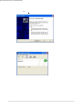
9.2 Starting up the Device Emulator
After installing all required software described in Chapter 9.1, follow the steps below to start up the
Device Emulator on your PC.
1.
2.
Figure 9.1
Terminology of Emulator and Simulator;
The Emulator described in this reference manual is a software application that behaves in a very
similar way to the actual device by imitating individual hardware components or protocols present in
the actual hardware.
On the other hand, the Simulator is also a software application that logically integrates application
programming interfaces (“API”) and certain other functions to allow debugging of the application
program using external events. The Emulator performs in a pseudo CPU and hardware
environment and it is impossible for the application to recognize whether it is in the actual device
environment or pseudo environment. However, actions carried out by the Simulator are not as
alike to those performed by actual components but merely mimic them very closely.
62
9.3 Debugging Applications
This chapter describes how to debug your application using the Device Emulator. Before starting
to “Build”, establish a connection between the DT-X7 and your PC via ActiveSync by referring to
Chapter 9.4 “Using the Device Emulator”.
For the basic order of developing an application, refer to Chapters 7. “eMbedded Visual C++” and 8.
“Visual Studio .NET 2003 and Visual Studio 2005”.
9.3.1 Setting Build Configuration
When using Visual Studio 2005
DT-X7 Emulator in the target device pull-down menu. See Figure 9.3.
Figure 9.3
When using eMbedded Visual C++ 4.0
C++ 4.0, Win32 (WCE ARMV4I) Debug in the Active Configuration pull-down menu, and
DT-X7 Device in the Default Device pull-down menu.
Figure 9.4
9.3.2 Debugging Applications
Basic Debug Operation
The debug operation used for the Device Emulator in both Visual Studio 2005 and eMbedded
Visual C++ 4.0 is the same as an ordinary debug operation using the actual terminal.
Debugging with the Device Emulator
With the Device Emulator, it is possible to set a break point in the source code of the application
for step-by-step debugging.
63
When using Visual Studio 2005
1
.
2
.
64
When using eMbedded Visual C++ 4.0
1. Establish a connection between the Device Emulator and PC via ActiveSync before starting
debugging in eMbedded Visual C++ 4.0. For establishing connection via ActiveSync, refer to
Chapter 9.4.3 “Connecting via ActiveSync”.
2. Navigate to Build in the menu bar → Start Debug → Go to start up debugging.
Figure 9.7
3. Similar to ordinary debugging operations with an actual DT-X7, the Device Emulator allows
break point setting (circled in red in Figure 9.8) in the source code and step-by-step debugging.
Figure 9.8
65
9.4 Using the Device Emulator
9.4.1 DT-X7 Device Emulator
The DT-X7 Device Emulator emulates various operations carried out by the actual DT-X7 device
on the PC’s screen such as mouse operation, input on PC’s keyboard, displaying execution of
applications, and operations by actual devices such as the scanner. Figure 9.9 shows an emulated
DT-X7 device on the screen of a PC.
Figure 9.9
Key Input
The emulator offers key input capability similar to that of the actual DT-X7 device. For instance, a
key on the emulated keyboard of DT-X7 on the screen (see Figure 9.9) can be clicked with the PC
mouse as well as key input made directly on the PC’s keyboard.
Reading Bar Codes
The emulator enables bar codes pre-registered in the I/O Simulator (see Figure 9.2) to be input when
clicking Trigger key on the emulated keyboard (see Figure 9.9). Note however that the Trigger key
must be continuously pressed for a second or more otherwise an incorrect key input may result.
Sound
The emulator offers beep and sound capability similar to that of the actual DT-X7 device.
66
Indications
The emulator offers a variety of indications on the screen (see Figures 9.10 and 9.11) for events
using the emulated components.
Table 9.1
Indication
LED (see Figure 9.10)
Vibrator ON/OFF
Low battery warning (see Figure
9.11)
Pressing
down Trigger key (see
Figure
9.10)
Figure 9.10
Description
The LED lights green when reading a bar code
successfully.
The emulated DT-X7 vibrates.
The low battery icon appears for low battery warning.
A triangle appears indicating that the trigger is being
pressed.
9.4.2 I/O Simulator
The I/O Simulator simulates registration of bar codes, generation of low battery warning, detection
of terminal being mounted on cradle.
Registration of bar code symbologies
1.
Click ADD button (circled in red in Figure 9.12) to go into the bar code registration mode.
Figure 9.12
2.
Select a bar code symbology in the Code Type pull-down menu that you wish to register in
the I/O Simulator.
Figure 9.13
68
3
.
Registration of bar code and note
Enter bar code data in the Barcode field (see Figure 9.14) and a note about the bar code in the
Note field if necessary. Click OK button to complete the bar code registration.
Figure 9.14
4
.
Completion of registration
After completion of the bar codes registration, the screen in Figure 9.15 shows a list of bar
codes that have been registered in the I/O Simulator. Prior to debugging with the Device
Emulator, make sure that you register all bar codes you wish to use in debugging.
Figure 9.15
69
5
.
Editing registered bar code content
Highlight a bar code in the list of registered bar codes (see Figure 9.15) and click Edit button.
Figure 9.16 appears for editing the bar code and its information.
Figure 9.16
6
.
Deleting registered bar code content
Highlight a bar code in the list of registered bar codes (see Figure 9.15) and click the Del
button. Dialogue screen in Figure 9.17 appears for you to confirm the deletion. If it is okay to
delete, click Yes button, otherwise click No button.
Figure 9.17
70
Detection of Terminal in Cradle / Low Battery Warning
If you check the I/O Box and Low Battery boxes in STATE SETTING (see Figure 9.18), the
simulator simulates the respective events in the emulator.
Figure 9.18
I/O Box
If this box is checked, a notification is issued that the connection between the DT-X7 Device
Emulator and cradle has been established. This notification can be utilized by the application.
Low Battery
If this box is checked, a notification that a low battery state has occurred is raised. The icon in the
toolbar in the emulated screen (see Figure 9.10) appears too. The notification can be utilized by the
application to recognize the low battery state in the hardware.
71
9.4.3 Connecting via ActiveSync
If debugging with the Device Emulator is carried out in either eMbedded Visual C++ 4.0 or
Visual Studio 2005, or transmission/reception of a file with the Device Emulator is carried out,
ActiveSync must be used.
Setting ActiveSync
1. Start up ActiveSync and then navigate to File → Connection Settings ….
Figure 9.19
2. In Connection Settings screen, check in the Allow connections to one of the following
box and select DMA in the pull-down menu. See Figure 9.20.
Figure 9.20
72
Connection via ActiveSync
The ways to establish connection of the Device Emulator via ActiveSync are ;
1. Start up the Device Emulator by referring to Chapter 9.2 “Starting up the Device Emulator”.
2. Start up Visual Studio 2005, and then navigate to Tools → Device Emulator Manager.
If Visual Studio 2005 is not available, start up the Standalone Device Emulator 1.0.
C:\Program Files\Microsoft Device Emulator\1.0\dvcemumanager.exe
3. Right-click DT-X7 Emulator in Available Emulators list and then select Cradle in the popup
menu. See Figure 9.21.
Figure 9.21
4. Make sure ActiveSync has started up and the
icon in the status bar appears. See the emulated
screen of DT-X7 in Figure 9.22. The icon indicates that the connection via ActiveSync has been
established.
Figure 9.22
74
10. Resources
Microsoft’s own http://msdn.microsoft.com/mobility/ is an extremely comprehensive resource for
programmers targeting WindowsCE .NET based devices. It includes links to most other useful web
based resources. You will find detailed Software, Library and .NET Library manuals on
http://world.casio.com/system/pa.