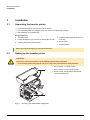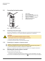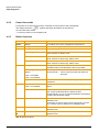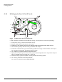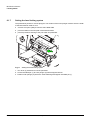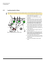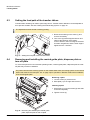
1
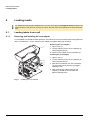
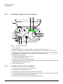
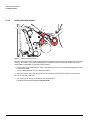
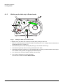
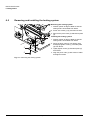
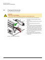
Transfer Printer BP-PR PLUS series Quick Operator’s Guide Edition 7/06 BP-PR PLUS series Information on the scope of delivery, appearance, performance, dimensions and weight reflect our knowledge at the time of printing. We reserve the right to make modifications. All rights, including those regarding the translation, are reserved. Approval The transfer printers comply with the following safety guidelines: CE EC Low-Voltage Directive (73/23/EEC) EC Machine Directive (98/37/EC) EC Electromagnetic Compatibility Directive (89/336/EEC) FCC Conditions from Part 15 of the FCC Regulations for Class A computing devices. Operation of this device may cause radio or television interference under unfavorable conditions, which would need to be remedied by the operator using countermeasures. W.H. Brady Lindestraat 21 Industriepark C3 9240 Zele Belgium Tel.: +32 52 457 811 e-mail: [email protected] 2 Identification Solutions Division 6555 W. Good Hope Road PO Box 2131 Milwaukee, WI 53201 U.S.A. Phone: 1-800-537-8791 Fax: 1-800-292-2289 Quick Operator’s Guide Edition 7/06 BP-PR PLUS series Notes on the documentation 1 Notes on the documentation The documentation for the BP-PR PLUS series transfer printers is comprised of the following parts: • Operating Instructions • Configuration Instructions • Service Instructions Additional documentation • Spare parts lists • Programming manual 2 Safety and the environment Read these operating instructions carefully before using the transfer printer for the first time. The operating instructions describe all of the functions of the transfer printer during operation. The available functions depend on the version used for a specific job. A detailed product description with all the technical data can be found in the “Configuration Instructions for the BP-PR PLUS series“. 2.1 Intended use • The transfer printer is a state-of-the-art device which complies with the recognized safety-related rules and regulations. Despite this, a danger to life and limb of the user or third parties could arise and the transfer printer or other property could be damaged while operating the device. • The transfer printer may only be used while in proper working order and for the intended purpose. Users must be safe, aware of potential dangers and must comply with the operating instructions! Faults, in particular those which affect safety, must be remedied immediately. • The transfer printer is solely intended to print suitable media which have been approved by the manufacturer. Any other or additional use is not intended. The manufacturer/supplier is not liable for damage resulting from misuse. Any misuse is at your own risk. • Intended use includes heeding the operating instructions, including the maintenance recommendations/regulations specified by the manufacturer. Edition 7/06 Quick Operator’s Guide 3 BP-PR PLUS series Safety and the environment 2.2 Safety notes • The transfer printer is designed for power supply systems from 100 V AC to 240 V AC. Connect the transfer printer only to electrical outlets with a ground contact. • Couple the transfer printer to devices using extra low voltage only. • Before making or undoing connections, switch off all devices involved (computer, printer, accessories etc.). • Operate the transfer printer in a dry environment only and do not get it wet (sprayed water, mist etc.). • If the transfer printer is operated with the cover open, ensure that clothing, hair, jewelry and similar personal items do not contact the exposed rotating parts. • The print mechanism can become hot during printing. Do not touch it during operation and allow it to cool down before changing the media or before removal or adjustment. • Carry out only the actions described in these operating instructions. Other tasks may only be performed by trained personnel or service technicians. DANGER! Risk of death via mains voltage! ⇒ Do not open the housing of the transfer printer. 2.3 Environmentally-friendly disposal Used devices contain valuable recyclable materials which should be utilized. ⇒ Dispose of used devices separately from other waste, i.e. via an appropriate collection site. The modular nature of the transfer printer allows it to easily be disassembled into its component parts so that the parts can be turned in for recycling. The PCB of the transfer printer has a lithium battery. ⇒ Dispose of this battery in a collection container for old batteries at the store or with the public waste disposal authority. 4 Quick Operator’s Guide Edition 7/06 BP-PR PLUS series Installation 3 Installation 3.1 Unpacking the transfer printer ⇒ Lift the transfer printer out of the box via the straps. ⇒ Check transfer printer for damage which may have occurred during transport. ⇒ Check delivery for completeness. Scope of delivery • Transfer printer • Dispense plate (peel-off device ver- • Empty cardboard core, mounted on ribbon take-up hub • Tear-off plate (basic devices only) sion only) • Power cable • Documentation Retain the original packaging for subsequent transport. 3.2 Setting up the transfer printer CAUTION! The device and the print media can be damaged by moisture and water. ⇒ The transfer printer may only be set up in a dry place protected from sprayed water. ⇒ Set up printer on a level surface. 1 ⇒ Open cover (1) of the transfer printer. ⇒ Remove foam transportation safeguards near the printhead (2). 2 Fig. 1: Edition 7/06 Removing the transportation safeguards Quick Operator’s Guide 5 BP-PR PLUS series Installation 3.3 Connecting the transfer printer 1 2 3 4 5 6 7 8 1 2 3 Power switch Power connection jack Slot for Cardbus or a Type II PC card Slot for a CompactFlash memory card Ethernet 10/100 Base-T USB port for a keyboard or scanner USB high-speed slave port Serial RS 232 C port 4 5 6 7 8 Fig. 2: 3.3.1 Power and computer connections Connecting to the power supply The printer is equipped with a versatile power supply unit. The device may be operated with a mains voltage of 230 V AC/ 50 Hz or 115 V AC/60 Hz without any adjustments or modifications. CAUTION! The device can be damaged by undefined switch-on currents. ⇒ Set the power switch (1) to "O" before plugging in the device. 1. Insert power cable into power connection jack (2). 2. Insert plug of the power cable into a grounded electrical outlet. 3.3.2 Connecting to a computer or computer network Insufficient or missing grounding can cause faults during operation. Ensure that all computers and connection cables connected to the transfer printer are grounded. ⇒ Connect transfer printer to computer or network with a suitable cable. Details on the configuration of the individual interfaces are found in the “Configuration Instructions“. 3.4 Switching the transfer printer on and off Once all connections have been made: ⇒ Switch printer on via the power switch (1). The printer runs through a system test and then indicates the system status Ready in the display. If an error has occurred while the system was starting up, the 6 Quick Operator’s Guide symbol and the error type are displayed. Edition 7/06 BP-PR PLUS series Operating panel 4 Operating panel 4.1 Layout of the operating panel The operating panel is comprised of the graphical display (1) and the navigator pad (2) with five integrated buttons. The graphical display informs you of the current status of the printer and the print job, reports errors and shows the printer settings in the menu. 1 The button functions are dependent on the current printer status: Active functions are indicated by the illuminated letters and symbols on the buttons of the navigator pad. 2 While printing, active functions illuminate white (e.g. menu or feed) Active functions are illuminated in orange in the offline menu (arrows, ↵ button) Fig. 3: Operating panel 4.2 Functions of the operating panel during printing 4.2.1 Symbol indicators The symbol indicators shown in the following table can appear on the status line of the screen, depending on the configuration of the printer. They inform you of the current status of the printer at a glance. For configuration of the status line, see the “Configuration Instructions“. Symbol Meaning Symbol Meaning Time Printhead temperature Date PPP credit Ribbon supply status User memory WLAN field strength Input buffer Ethernet status Printer receiving data Tab. 1: Indicator symbols during printing Edition 7/06 Quick Operator’s Guide 7 BP-PR PLUS series Operating panel 4.2.2 Power-Save mode If the printer is not used for some time, it switches to Power-Save mode automatically. The display shows the graphic and button illumination is switched off. To exit Power-Save mode: ⇒ Press any button on the navigator pad. 4.2.3 Button functions Button State Function menu Ready Go to offline menu (see “Configuration Instructions“) feed Ready Advances an empty label pause Ready Repeat printing of last label Printing Label Pause print job, printer switches to Pause mode Pause Continue print job, printer switches to Printing Label mode Fault - correctable Continue print job after error recovery, printer switches to Printing Label mode Ready Clear print buffer, repeated printing of the last label is then not possible Printing Label Press briefly→ Pause Press and hold→ cancel current print job and delete all print jobs cancel Fault - correctable cancel current print job Fault - irrecoverable ↵ button System error Press → if the error occurs repeatedly, notify the Service Department Fault - correctable Call up help→ brief information on error recovery is displayed Fault - irrecoverable Offline menu Press briefly to enable value selection on the parameter level, accept a selected value or start a function Press and hold (> 2 sec.) to exit the parameter level without accepting the parameter setting W Offline menu Select menu items on a menu level or to select values on the parameter level Press button on the top menu level several times, if necessary, to switch from the offline menu to Ready mode X Offline menu Select menu items on a menu level or to select values on the parameter level S T Offline menu Reach a higher or lower menu level or set values on the parameter level Tab. 2: Button functions 8 Quick Operator’s Guide Edition 7/06 BP-PR PLUS series Device types 5 Device types 5.1 Standard device The standard device is used for printing labels or continuous media on rolls or fanfolded media. In Tear-Off mode, labels are removed by hand. The labels can be cut off automatically with the 'cutter' accessory. For details, see the Operating Instructions for the 'cutter' accessory. The labels can be wound up with the 'external rewinder' accessory. For details, see the Operating Instructions for the 'external rewinder' accessory. Because there is no internal rewinder, automatic peeling off of the labels from the carrier medium (PeelOff mode) and internal rewinding are not possible. 5.2 Peel-off device version The peel-off device version is capable of Peel-Off mode and thus has an internal rewinder and a pulling system comprised of a rewind assist roller and a locking system. Printing on labels or continuous media from rolls or fanfolded media is possible. Operation in Tear-Off mode and with the 'cutter' or 'external rewinder' accessory is possible by installing the tear-off plate (see ”6.4” on page 17), as with the standard device. In Peel-Off mode, the label is peeled off the liner after printing. The label can be removed by hand with the peel-off sensor (accessory). Label removal can also occur automatically via the applicator (accessory). The liner is rolled up via the internal rewinder. For use in Internal Rewind mode remove the locking system (see ”6.5” on page 18) and replace the dispense plate with a rewind guide plate (see ”6.4” on page 17). Edition 7/06 Quick Operator’s Guide 9 BP-PR PLUS series Loading media 6 Loading media For adjustments and simple installation work, use the accompanying hexagonal wrench located in the bottom section of the print unit. See Fig. 5, Item 8. No other tools are required for the work described here. 6.1 Loading labels from a roll 6.1.1 Removing and installing the core adapter A core adapter is mounted for better guidance of the label roll on the roll retainer when using label rolls with a core diameter ≥ 75 mm. Remove core adapter for smaller label rolls as follows. Removing the core adapter 1 1. Open cover (1). 2. Loosen retaining screws of core adapter (2) with hexagonal wrench. 3. Remove core adapter from roll retainer (4). Installing the core adapter 1. Open cover (1). 2 2. Loosen retaining screws of core adapter (2) with hexagonal wrench. 3 4 3. Slide first core adapter onto the roll retainer (4) until it stops at the housing and tighten retaining screw. 4. Slide second core adapter onto the roll retainer (4) based on the roll width and tighten retaining screw. Fig. 4: 10 Installing the core adapter Quick Operator’s Guide Edition 7/06 BP-PR PLUS series Loading media 6.1.2 Positioning the label roll on the roll retainer 1 2 10 9 3 4 8 Fig. 5: 7 6 5 Loading labels from a roll 1. Open cover (10). 2. Loosen knurled screw (1) and swivel guide (2) upward and push it all the way out. 3. Remove core adapter (4) for label rolls with a core diameter ≤ 75 mm (see ”6.1.1” on page 10). 4. Load label roll on the roll retainer in such a way that the labels can be inserted into the printhead in the right position. The printing side of the labels must be visible from above. 5. Supplying longer label strips: For Peel-Off or Rewind mode: approx. 60 cm For Tear-Off mode: approx. 40 cm 6. Push label roll until it contacts the housing wall. 7. Swivel guide (2) downward onto the roll retainer (3) and push it against the label roll so that the roll is braked slightly while supplying media. 8. Tighten knurled screw (1). 6.1.3 Inserting a label strip into the printhead 1. Turn lever (9) counterclockwise to lift the printhead. 2. Push guide ring on axis (6) all the way out. 3. Guide label strip to the print unit above the internal rewinder (5). 4. Guide label strips below the axis (6) and through the label sensor (7) in such a way that it exits the print unit between the printhead and the print roller. 5. Push guide ring on axis (6) against the outer edge of the label strip. Edition 7/06 Quick Operator’s Guide 11 BP-PR PLUS series Loading media 6.1.4 Setting the label sensor 1 2 3 Fig. 6: Setting the label sensor The label sensor (2) can be shifted perpendicular to the direction of paper flow for adaptation to the label medium. The sensor unit (1) of the label sensor is visible from the front through the print unit and is marked with a indentation in the label sensor retainer. ⇒ Position label sensor with tab (3) in such a way that the sensor (1) can detect the label gap or a reflex or perforation mark. - or, if the labels deviate from a rectangular shape, ⇒ Align label sensor using the tab (3) with the front edge of the label in the direction of paper flow. For use in Tear-Off mode only: ⇒ Turn lever (Fig. 5, Item 9) clockwise to lock the printhead. The label roll is loaded for use in Tear-Off mode. 12 Quick Operator’s Guide Edition 7/06 BP-PR PLUS series Loading media 6.1.5 Winding up the label strip in Rewind mode 5 4 3 2 1 Fig. 7: Guiding the label strip in Rewind mode In Rewind mode, the labels are wound up internally after printing for later use. 1. Remove the locking system for Rewind mode if necessary (see ”6.5” on page 18) and install rewind guide plate (see ”6.4” on page 17). 2. Guide label strip around the rewind guide plate (4) to the internal rewinder (2). 3. Hold rewinder (2) firmly and turn knob (3) clockwise until it stops. 4. Push label strip under a bracket (1) of the rewinder and turn knob (3) counterclockwise until it stops. The rewinder is fully spread, thus gripping the label strip firmly. 5. Turn rewinder (2) counterclockwise to tighten the label strip. 6. Turn lever (5) clockwise to lock the printhead. The label roll is loaded for use in Rewind mode. Edition 7/06 Quick Operator’s Guide 13 BP-PR PLUS series Loading media 6.1.6 Winding up the liner in Peel-Off mode 7 6 5 4 Fig. 8: 3 2 1 Guidance of the liner in Peel-Off mode In Peel-Off mode, the labels are removed after printing, and only the liner is wound up internally. 1. Lift the pinch roller (4) off the rewind assist roller (5). 2. Remove labels from the first 100 mm of the liner. 3. Guide liner to the rewinder (2) around the dispense plate (6) and the rewind assist roller (5). 4. Hold rewinder (2) firmly and turn knob (3) clockwise until it stops. 5. Push liner under a bracket (1) of the rewinder (2) and turn knob (3) counterclockwise until it stops. The rewinder is fully spread, thus gripping the liner firmly. 6. Turn rewinder (2) counterclockwise to tighten the liner. 7. Slightly loosen top fixing screw at the locking system with hexagonal wrench and position the pinch roller (4) centrally to the liner (see ”6.5” on page 18). 8. Close the locking system and tighten top fixing screw at the locking system. 9. Turn lever (7) clockwise to lock the printhead. The label roll is loaded for use in Peel-Off mode. 14 Quick Operator’s Guide Edition 7/06 BP-PR PLUS series Loading media 6.1.7 Setting the head locking system The printhead is pushed on via two plungers. The location of the outer plunger must be set to the width of the label medium used so as to • achieve even print quality across the entire label width • prevent wrinkles in the feed path of the transfer ribbon • prevent premature wearing of the print roller and printhead. 1 2 3 Fig. 9: Setting the head locking system 1. Turn lever (3) clockwise to lock the printhead. 2. Loosen threaded pin (1) at outer plunger (2) with hexagonal wrench. 3. Position outer plunger (2) above the outer label edge and tighten threaded pin (1). Edition 7/06 Quick Operator’s Guide 15 BP-PR PLUS series Loading media 6.2 Loading transfer ribbon With direct thermal printing, do not load a transfer ribbon; if one has already been loaded, remove it. 1 2 3 1. Clean printhead before loading the transfer ribbon (see ”8.3” on page 20). 2. Turn lever (4) counterclockwise to lift the printhead. 3. Slide transfer ribbon roll (2) onto the ribbon supply hub (3) until it stops and so that the color coating of the ribbon faces downward when being unwound. No rotation direction is specified for the ribbon supply hub (3). 4. Hold transfer ribbon roll (2) firmly and turn knob on ribbon supply hub (3) counterclockwise until the transfer ribbon roll is secured. 4 5. Slide suitable transfer ribbon core onto the transfer ribbon take-up hub (1) and secure it in the same way. 6. Guide transfer ribbon through the print unit as shown in Fig. 10. Fig. 10: Feed path of the transfer ribbon 7. Secure starting end of transfer ribbon to the transfer ribbon core (1) with adhesive tape. Ensure counterclockwise rotation direction of the transfer ribbon take-up hub here. 8. Turn transfer ribbon take-up hub (1) counterclockwise to smooth out the feed path of the transfer ribbon. 9. Turn lever (4) clockwise to lock the printhead. 16 Quick Operator’s Guide Edition 7/06 BP-PR PLUS series Loading media 6.3 Setting the feed path of the transfer ribbon Transfer ribbon wrinkling can lead to print image errors. Transfer ribbon deflection can be adjusted so as to prevent wrinkles. See also “Setting the head locking system” on page 15. The adjustment is best carried out during printing. 1. Read current setting on the scale (1) and record if necessary. 1 2. Turn screw (2) with hexagonal wrench and observe the behavior of the ribbon. In the + direction, the inner edge of the transfer ribbon is tightened, and the outer edge is tightened in the - direction. 2 Fig. 11: Setting the feed path of the transfer ribbon 6.4 Removing and installing the rewind guide plate, dispense plate or tear-off plate To convert the printer for use in another operating mode, a rewind guide plate, a dispense plate or a tearoff plate may need to be installed. For printer versions with a locking system on the rewind assist roller, the locking system on the rewind assist roller must be removed (see ”6.5” on page 18) for operation in Rewind mode before installation of the rewind guide plate. Removing a plate 1. Loosen screws (2) several turns. 2. Slide plate (1) to the right and remove it. Installing a plate 1. Place plate (1) onto the screws (2) and slide to the left completely. 2. Tighten screws (2). 2 1 2 Fig. 12: Removing and installing the rewind guide plate, dispense plate or tear-off plate Edition 7/06 Quick Operator’s Guide 17 BP-PR PLUS series Loading media 6.5 Removing and installing the locking system Removing the locking system 1. Position printer at edge of table so that the oblong hole is accessible from below. 2. Screw out screws (1) (2) and remove them. 3. Remove the pinch roller (4) and bottom plate (3). 1 Installing the locking system 1. Position printer at edge of table so that the oblong hole is accessible from below. 2. Place the pinch roller (4) into oblong hole and lightly tighten screw (1) of bottom plate (3) from above. 4 3 3. Lightly tighten screw (2) of bottom plate (3) from below. 2 4. Align the pinch roller (4) with center of label and tighten screws. Fig. 13: Removing the locking system 18 Quick Operator’s Guide Edition 7/06 BP-PR PLUS series Printing 7 Printing CAUTION! The printhead can be damaged if handled improperly! ⇒ Do not touch the bottom of the printhead with your fingers or sharp objects. ⇒ Ensure that the labels are clean. ⇒ Ensure smooth label surfaces. Raw labels are like emery and reduce the service life of the printhead. ⇒ Print at the lowest possible printhead temperature. 7.1 Synchronization The printer is ready for operation when all connections have been made, the labels and, if necessary the transfer ribbon, have been loaded and the printhead is locked. For details on printer configuration, see the “Configuration Instructions“. After loading the label medium, synchronization is necessary. During synchronization, the printer automatically determines the length of the loaded labels and sets label advancement accordingly. 1. Press the feed button to start synchronization. 2. Remove empty labels after synchronization. The printer is synchronized with the loaded label medium. Synchronization is not necessary if the printhead was not opened between different print jobs, even if the printer was switched off. 7.2 Tear-Off mode In Tear-Off mode, labels or continuous media are printed. After printing, the label strip is separated by hand. The transfer printer is equipped with a tear-off plate for this. Optionally, the label can be cut off or label strips can be wound up externally. 7.3 Peel-Off mode In Peel-Off mode, the labels are automatically peeled off the carrier medium after printing and presented for removal. The transfer printer is equipped with a dispense plate and one of the following accessory devices for this: peel-off sensor (PS6 or PS8), peel-off adapter (PS5) or applicator (A1000). The carrier medium is wound up inside the printer. 7.4 Internal rewinding The labels are wound up internally after printing with the carrier medium for later use. The transfer printer is equipped with a rewind guide plate for this. Edition 7/06 Quick Operator’s Guide 19 BP-PR PLUS series Cleaning and basic maintenance 8 Cleaning and basic maintenance DANGER! Risk of death via electric shock! ⇒ Disconnect the printer from the power supply before performing any maintenance work. 8.1 General cleaning When: as necessary. CAUTION! Abrasive cleaning agents can damage the printer! ⇒ Do not use abrasives or solvents to clean the outer surfaces or assemblies. ⇒ Remove dust and paper fuzz in the printing area with a soft brush or vacuum cleaner. ⇒ Clean outer surfaces with an all-purpose cleaner. 8.2 Cleaning the print roller When: each time the label roll is changed or when the print image and label transport are adversely affected. 1. Turn lever (4, Fig. 10) counterclockwise to lift the printhead. 2. Remove labels and transfer ribbon from the printer. 3. Remove deposits with roller cleaner and a soft cloth. 4. If the roller appears damaged, replace it. 8.3 Cleaning the printhead When: • direct thermal printing: each time the label roll is changed • thermal transfer printing: each time the transfer ribbon is changed or when the print image is adversely affected Substances may accumulate on the printhead during printing and adversely affect printing, e.g. differences in contrast or vertical stripes. CAUTION! Printhead can be damaged! ⇒ Do not use sharp or hard objects to clean the printhead. ⇒ Do not touch protective glass layer of the printhead. 1. Turn lever (4, Fig. 10) counterclockwise to lift the printhead. 2. Remove labels and transfer ribbon from the printer. 3. Clean printhead surface with special cleaning pen or a cotton swab dipped in pure alcohol. 4. Allow printhead to dry for 2–3 minutes before commissioning the printer. 20 Quick Operator’s Guide Edition 7/06 BP-PR PLUS series Cleaning and basic maintenance 8.4 Cleaning the label sensor When: when the label roll is changed CAUTION! Label sensor can be damaged! ⇒ Do not use sharp or hard objects or solvents to clean the label sensor. The label sensor can become dirtied with paper dust. This can adversely affect label detection. 1. Turn lever (1) counterclockwise to lift the printhead. 2. Remove labels and transfer ribbon from the printer. 3. Remove hexagonal wrench (5) from its retainer. 1 4. Press the latch (3) and slowly pull label sensor outward via the tab (4). Ensure that the label sensor cable is not tensioned by this. 2 3 5. Clean label sensor and sensor units (2) with brush or cotton swab soaked in pure alcohol. 6. Push label sensor back via tab (3) and set it (see ”6.1.4” on page 12). 5 4 7. Push hexagonal wrench (5) into retainer. 8. Reload labels and transfer ribbon (see ”6.1” on page 10). Fig. 14: Cleaning the label sensor Edition 7/06 Quick Operator’s Guide 21 BP-PR PLUS series EC Declaration of Conformity 9 EC Declaration of Conformity *HVHOOVFKDIWIU&RPSXWHU und Automations%DXVWHLQHPE+&R.* :LOKHOP6FKLFNDUG6WU '.DUOVUXKH EU Conformity Declaration We declare herewith that as a result of the manner in which the machine designated below was designed, the type of construction and the machines which, as a result have been brought on to the general market comply with the relevant fundamental regulations of the EU Rules for Safety and Health. In the event of any alteration which has not been approved by us being made to any machine as designated below, this statement shall thereby be made invalid. Description : Type : Transfer Printer BP-PR PLUS series Applied EU Regulations and Norms: - EC Machinery Regulations - Machine Safety 98/37/EU EN ISO 12100-1:2003 EN ISO 12100-2:2003 - EC Low Voltage Regulations 'DWDDQG2I¿FH0DFKLQH6DIHW\ 73/23/EEC (1 - EC Electromagnetic Compatibility Regulations 7KUHVKROGYDOXHVIRUWKH,QWHUIHUHQFH of Data Machines /LPLWVIRUKDUPRQLFFXUUHQWHPLVVLRQ /LPLWVRIYROWDJHÀXFWXDWLRQDQGÀLFNHU ,PPXQLW\FKDUDFWHULVWLFV Limits and methods of measurement 89/336/EEC (1$$&ODVV$ (1 (1$ (1$$ Signed for, and on behalf of, the Manufacturer : cab Produkttechnik Sömmerda *HVHOOVFKDIWIU&RPSXWHU und Automationsbausteine mbH 6|PPHUGD 6|PPHUGD7 Erwin Fascher Managing Director 22 Quick Operator’s Guide Edition 7/06