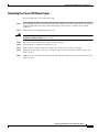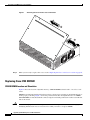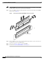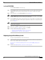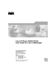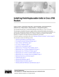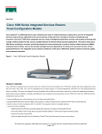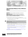
1
Upgrading System Memory in Cisco 3700 Series
Routers
Product Numbers:
MEM3725-32CF-INCL, MEM3725-32U64CF, MEM3725-32U128CF, MEM3725-32CF=, MEM3725-64CF=,
MEM3725-128CF=
MEM3725-64D=, MEM3725-128D=
MEM3745-256D-INCL, MEM3745-256D=, MEM3745-128CF=, MEM3745-128D-INCL, MEM3745-128D=,
MEM3745-128U192D, MEM3745-128U256D, MEM3745-256U512D, MEM3745-32CF-INCL, MEM3745-32CF=,
MEM3745-32U128CF, MEM3745-32U64CF, MEM3745-64CF=, MEM3745-64D=
This document describes how to upgrade the following in a Cisco 3700 series router:
Note
•
Synchronized dynamic random-access memory (SDRAM) dual in-line memory modules (DIMMs)
•
Small-outline dual in-line memory modules (SODIMMs)
•
Cisco 3700 CompactFlash memory cards.
In this document, the term “Cisco 3700 series” represents the following router models: Cisco 3725
router and Cisco 3745 router.
Use this document in conjunction with the following:
•
Cisco 3700 Series Hardware Installation Guide and the Cisco 2600 Series, Cisco 3600 Series, and
Cisco 3700 Series Regulatory Compliance and Safety Information document for your router, both
available online at the following URL:
•
http://www.cisco.com/univercd/cc/td/doc/product/access/acs_mod/cis3700/hw_inst/index.htm
•
Installing and Formatting Cisco 2691, Cisco 3631, and Cisco 3700 Series CompactFlash Memory
Cards, available online at the following URL:
•
http://www.cisco.com/univercd/cc/td/doc/product/access/acs_mod/cis3700/hw_inst/hw_notes/
comflash.htm
If you have questions or need help, see the “Obtaining Documentation” section on page 27 and the
“Obtaining Technical Assistance” section on page 28 for further information.
Corporate Headquarters:
Cisco Systems, Inc., 170 West Tasman Drive, San Jose, CA 95134-1706 USA
Copyright © 2004 Cisco Systems, Inc. All rights reserved.
Memory Capacities
This document contains the following sections:
•
Memory Capacities, page 2
•
Memory Configurations, page 3
•
Safety Recommendations, page 4
•
Tools and Equipment Needed, page 10
•
Upgrading System Memory in Cisco 3725 Routers, page 10
•
Upgrading System Memory in Cisco 3745 Routers, page 17
•
Recovering Compact Flash Memory and System Images, page 27
•
Obtaining Documentation, page 27
•
Documentation Feedback, page 28
•
Obtaining Technical Assistance, page 28
•
Obtaining Additional Publications and Information, page 29
Memory Capacities
You might need to upgrade memory for the following reasons:
•
To upgrade to a new Cisco IOS feature set or release that requires additional memory. (Memory
requirements for each feature set and release are available in the release notes for that release.)
•
To use very large routing tables, many protocols (as may be required, for example, when the router
is part of both a large external network and your internal network), or other memory-intensive
features such as spoofing or protocol translations.
This document describes how to upgrade both dynamic memory and compact flash memory. Cisco 3700
series routers use dynamic memory in the form of SDRAM DIMMs (Cisco 3725 router) or SDRAM
SODIMMs (Cisco 3745 router). Memory capacities are shown in Table 1.
Table 1
Note
Memory Capacities for Cisco 3700 Series Routers
Router
DRAM
Compact Flash Memory
Cisco 3725
256- (default) to 256-MB SDRAM DIMMs
32- (default) to 128-MB memory card
Cisco 3745
256- (default) to 512-MB SDRAM SODIMMs 32- (default) to 128-MB memory card
This document discusses how to replace dynamic memory only. To learn how to replace CompactFlash
memory cards, refer to Installing and Formatting Cisco 2691, Cisco 3631, and Cisco 3700 Series
CompactFlash Memory Cards, available online at the following URL:
http://www.cisco.com/univercd/cc/td/doc/product/access/acs_mod/cis3700/hw_inst/hw_notes/
index.htm.
Upgrading System Memory in Cisco 3700 Series Routers
2
OL-5423-02
Memory Configurations
Memory Configurations
For information on configuring dynamic memory and compact flash memory, see the following sections.
Dynamic Memory
You can configure dynamic memory (SDRAM) as a mixture of primary or main memory that is reserved
for the CPU and shared memory that is used for data transmitted or received by modules and WAN
interface cards.
To examine current dynamic memory status or reconfigure memory allocation, do the following, as
appropriate:
Step 1
To see how much memory is currently installed in your router, enter the show version command in
EXEC mode. Near the middle of the resulting output, locate a message similar to the following:
Cisco XXXX processor (revision X) with 24576K/8192K bytes of memory.
This line shows how much memory is installed (in this example, 24576K/8192K). The first number
represents primary memory; the second number represents shared memory.
Step 2
Note
To configure the proportion of SDRAM devoted to main memory and to shared memory, enter the
memory-size iomem command in global configuration mode.
For information about these and related commands, refer to the Cisco IOS configuration guides and
command references. See the “Obtaining Documentation” section on page 27 for information about
these publications.
Dynamic memory resides in one or two sockets in the router chassis. A socket corresponds to one bank
of memory. Cisco 3700 series router sockets are as follows:
•
Cisco 3725: Two sockets, each of which can support one SDRAM DIMM or be left empty; sockets
can be filled in any order
•
Cisco 3745: One socket that can support two SDRAM SODIMMs, one on top of the other
SDRAM DIMM and SODIMM sizes allowed in each router type, and the total memory capacity
resulting from insertion of one or two DIMMs or SODIMMs, are shown in Table 2.
Upgrading System Memory in Cisco 3700 Series Routers
OL-5423-02
3
Safety Recommendations
Table 2
SDRAM Configurations for Cisco 3700 Series Routers
Router
DIMM or SODIMM 0
DIMM or SODIMM 1
Total Memory
3725/3745
128 MB (default)
128 MB (default)
256 MB
—
128 MB
128 MB
64 MB
128 MB
192 MB
128 MB
64 MB
192 MB
128 MB
128 MB
256 MB
256 MB
—
256 MB
—
256 MB
256 MB
64 MB
256 MB
320 MB
256 MB
64 MB
320 MB
128 MB
256 MB
384 MB
256 MB
128 MB
384 MB
256 MB
256 MB
512 MB
3745
Compact Flash Memory
Cisco IOS software on Cisco 3700 series routers is stored in two CompactFlash memory cards—one
external and one internal. Memory cards come with 32-, 64-, or 128-MB of memory.
To determine how much compact flash memory is installed in your router, enter the show flash command
in EXEC mode.
Note
To install a new CompactFlash memory card, refer to Installing and Formatting Cisco 2691, Cisco 3631,
and Cisco 3700 Series CompactFlash Memory Cards, available online at the following URL:
http://www.cisco.com/univercd/cc/td/doc/product/access/acs_mod/cis3700/hw_inst/hw_notes/
index.htm
Safety Recommendations
Follow these guidelines to ensure general safety:
•
Keep the chassis area clear and dust-free during and after installation.
•
Place the removed chassis cover in a safe place.
•
Keep tools away from walk areas where you or others could fall over them.
•
Do not wear loose clothing that could get caught in the chassis. Fasten your tie or scarf and roll up
your sleeves.
•
Wear safety glasses when working under any conditions that might be hazardous to your eyes.
•
Do not perform any action that creates a potential hazard to people or makes equipment unsafe.
Upgrading System Memory in Cisco 3700 Series Routers
4
OL-5423-02
Safety Recommendations
Safety Warnings
Safety warnings appear throughout this publication in procedures that, if performed incorrectly, may
harm you. A warning symbol precedes each warning statement.
Warning Definition
Warning
IMPORTANT SAFETY INSTRUCTIONS
This warning symbol means danger. You are in a situation that could cause bodily injury. Before you
work on any equipment, be aware of the hazards involved with electrical circuitry and be familiar
with standard practices for preventing accidents. To see translations of the warnings that appear in
this publication, refer to the translated safety warnings that accompanied this device.
Note: SAVE THESE INSTRUCTIONS
Note: This documentation is to be used in conjunction with the specific product installation guide
that shipped with the product. Please refer to the Installation Guide, Configuration Guide, or other
enclosed additional documentation for further details. Statement 1020
Waarschuwing
BELANGRIJKE VEILIGHEIDSINSTRUCTIES
Dit waarschuwingssymbool betekent gevaar. U verkeert in een situatie die lichamelijk letsel kan
veroorzaken. Voordat u aan enige apparatuur gaat werken, dient u zich bewust te zijn van de bij
elektrische schakelingen betrokken risico's en dient u op de hoogte te zijn van de standaard
praktijken om ongelukken te voorkomen. Voor een vertaling van de waarschuwingen die in deze
publicatie verschijnen, dient u de vertaalde veiligheidswaarschuwingen te raadplegen die bij dit
apparaat worden geleverd.
Opmerking BEWAAR DEZE INSTRUCTIES.
Opmerking Deze documentatie dient gebruikt te worden in combinatie met de
installatiehandleiding voor het specifieke product die bij het product wordt geleverd. Raadpleeg de
installatiehandleiding, configuratiehandleiding of andere verdere ingesloten documentatie voor
meer informatie.
Varoitus
TÄRKEITÄ TURVALLISUUTEEN LIITTYVIÄ OHJEITA
Tämä varoitusmerkki merkitsee vaaraa. Olet tilanteessa, joka voi johtaa ruumiinvammaan. Ennen
kuin työskentelet minkään laitteiston parissa, ota selvää sähkökytkentöihin liittyvistä vaaroista ja
tavanomaisista onnettomuuksien ehkäisykeinoista. Tässä asiakirjassa esitettyjen varoitusten
käännökset löydät laitteen mukana toimitetuista ohjeista.
Huomautus SÄILYTÄ NÄMÄ OHJEET
Huomautus Tämä asiakirja on tarkoitettu käytettäväksi yhdessä tuotteen mukana tulleen
asennusoppaan kanssa. Katso lisätietoja asennusoppaasta, kokoonpano-oppaasta ja muista
mukana toimitetuista asiakirjoista.
Upgrading System Memory in Cisco 3700 Series Routers
OL-5423-02
5
Safety Recommendations
Attention
IMPORTANTES INFORMATIONS DE SÉCURITÉ
Ce symbole d'avertissement indique un danger. Vous vous trouvez dans une situation pouvant causer
des blessures ou des dommages corporels. Avant de travailler sur un équipement, soyez conscient
des dangers posés par les circuits électriques et familiarisez-vous avec les procédures couramment
utilisées pour éviter les accidents. Pour prendre connaissance des traductions d'avertissements
figurant dans cette publication, consultez les consignes de sécurité traduites qui accompagnent cet
appareil.
Remarque CONSERVEZ CES INFORMATIONS
Remarque Cette documentation doit être utilisée avec le guide spécifique d'installation du produit
qui accompagne ce dernier. Veuillez vous reporter au Guide d'installation, au Guide de
configuration, ou à toute autre documentation jointe pour de plus amples renseignements.
Warnung
WICHTIGE SICHERHEITSANWEISUNGEN
Dieses Warnsymbol bedeutet Gefahr. Sie befinden sich in einer Situation, die zu einer
Körperverletzung führen könnte. Bevor Sie mit der Arbeit an irgendeinem Gerät beginnen, seien Sie
sich der mit elektrischen Stromkreisen verbundenen Gefahren und der Standardpraktiken zur
Vermeidung von Unfällen bewusst. Übersetzungen der in dieser Veröffentlichung enthaltenen
Warnhinweise sind im Lieferumfang des Geräts enthalten.
Hinweis BEWAHREN SIE DIESE SICHERHEITSANWEISUNGEN AUF
Hinweis Dieses Handbuch ist zum Gebrauch in Verbindung mit dem Installationshandbuch für Ihr
Gerät bestimmt, das dem Gerät beiliegt. Entnehmen Sie bitte alle weiteren Informationen dem
Handbuch (Installations- oder Konfigurationshandbuch o. Ä.) für Ihr spezifisches Gerät.
Figyelem!
FONTOS BIZTONSÁGI ELÕÍRÁSOK
Ez a figyelmezetõ jel veszélyre utal. Sérülésveszélyt rejtõ helyzetben van. Mielõtt bármely
berendezésen munkát végezte, legyen figyelemmel az elektromos áramkörök okozta kockázatokra,
és ismerkedjen meg a szokásos balesetvédelmi eljárásokkal. A kiadványban szereplõ
figyelmeztetések fordítása a készülékhez mellékelt biztonsági figyelmeztetések között található.
Megjegyzés ÕRIZZE MEG EZEKET AZ UTASÍTÁSOKAT!
Megjegyzés Ezt a dokumentációt a készülékhez mellékelt üzembe helyezési útmutatóval együtt kell
használni. További tudnivalók a mellékelt Üzembe helyezési útmutatóban (Installation Guide),
Konfigurációs útmutatóban (Configuration Guide) vagy más dokumentumban találhatók.
Avvertenza
IMPORTANTI ISTRUZIONI SULLA SICUREZZA
Questo simbolo di avvertenza indica un pericolo. La situazione potrebbe causare infortuni alle
persone. Prima di intervenire su qualsiasi apparecchiatura, occorre essere al corrente dei pericoli
relativi ai circuiti elettrici e conoscere le procedure standard per la prevenzione di incidenti. Per le
traduzioni delle avvertenze riportate in questo documento, vedere le avvertenze di sicurezza che
accompagnano questo dispositivo.
Nota CONSERVARE QUESTE ISTRUZIONI
Nota La presente documentazione va usata congiuntamente alla guida di installazione specifica
spedita con il prodotto. Per maggiori informazioni, consultare la Guida all'installazione, la Guida
alla configurazione o altra documentazione acclusa.
Upgrading System Memory in Cisco 3700 Series Routers
6
OL-5423-02
Safety Recommendations
Advarsel
VIKTIGE SIKKERHETSINSTRUKSJONER
Dette varselssymbolet betyr fare. Du befinner deg i en situasjon som kan forårsake personskade.
Før du utfører arbeid med utstyret, bør du være oppmerksom på farene som er forbundet med
elektriske kretssystemer, og du bør være kjent med vanlig praksis for å unngå ulykker. For å se
oversettelser av advarslene i denne publikasjonen, se de oversatte sikkerhetsvarslene som følger
med denne enheten.
Merk TA VARE PÅ DISSE INSTRUKSJONENE
Merk Denne dokumentasjonen skal brukes i forbindelse med den spesifikke
installasjonsveiledningen som fulgte med produktet. Vennligst se installasjonsveiledningen,
konfigureringsveiledningen eller annen vedlagt tilleggsdokumentasjon for detaljer.
Aviso
INSTRUÇÕES IMPORTANTES DE SEGURANÇA
Este símbolo de aviso significa perigo. O utilizador encontra-se numa situação que poderá ser
causadora de lesões corporais. Antes de iniciar a utilização de qualquer equipamento, tenha em
atenção os perigos envolvidos no manuseamento de circuitos eléctricos e familiarize-se com as
práticas habituais de prevenção de acidentes. Para ver traduções dos avisos incluídos nesta
publicação, consulte os avisos de segurança traduzidos que acompanham este dispositivo.
Nota GUARDE ESTAS INSTRUÇÕES
Nota Esta documentação destina-se a ser utilizada em conjunto com o manual de instalação
incluído com o produto específico. Consulte o manual de instalação, o manual de configuração ou
outra documentação adicional inclusa, para obter mais informações.
¡Advertencia!
INSTRUCCIONES IMPORTANTES DE SEGURIDAD
Este símbolo de aviso indica peligro. Existe riesgo para su integridad física. Antes de manipular
cualquier equipo, considere los riesgos de la corriente eléctrica y familiarícese con los
procedimientos estándar de prevención de accidentes. Vea las traducciones de las advertencias
que acompañan a este dispositivo.
Nota GUARDE ESTAS INSTRUCCIONES
Nota Esta documentación está pensada para ser utilizada con la guía de instalación del producto
que lo acompaña. Si necesita más detalles, consulte la Guía de instalación, la Guía de
configuración o cualquier documentación adicional adjunta.
Varning!
VIKTIGA SÄKERHETSANVISNINGAR
Denna varningssignal signalerar fara. Du befinner dig i en situation som kan leda till personskada.
Innan du utför arbete på någon utrustning måste du vara medveten om farorna med elkretsar och
känna till vanliga förfaranden för att förebygga olyckor. Se översättningarna av de
varningsmeddelanden som finns i denna publikation, och se de översatta säkerhetsvarningarna som
medföljer denna anordning.
OBS! SPARA DESSA ANVISNINGAR
OBS! Denna dokumentation ska användas i samband med den specifika
produktinstallationshandbok som medföljde produkten. Se installationshandboken,
konfigurationshandboken eller annan bifogad ytterligare dokumentation för närmare detaljer.
Upgrading System Memory in Cisco 3700 Series Routers
OL-5423-02
7
Safety Recommendations
Warning
Only trained and qualified personnel should be allowed to install, replace, or service this equipment.
Statement 1030
Warning
Ultimate disposal of this product should be handled according to all national laws and regulations.
Statement 1040
Upgrading System Memory in Cisco 3700 Series Routers
8
OL-5423-02
Safety Recommendations
Safety with Electricity
Warning
Never touch uninsulated telephone wires or terminals unless the telephone line has been
disconnected at the network interface. Statement 1037
Warning
Do not work on the system or connect or disconnect cables during periods of lightning activity.
Statement 1001
Warning
To avoid electric shock, do not connect safety extra-low voltage (SELV) circuits to telephone-network
voltage (TNV) circuits. LAN ports contain SELV circuits, and WAN ports contain TNV circuits. Some
LAN and WAN ports both use RJ-45 connectors. Use caution when connecting cables. Statement 1021
Warning
Hazardous network voltages are present in WAN ports regardless of whether power to the unit is OFF
or ON. To avoid electric shock, use caution when working near WAN ports. When detaching cables,
detach the end away from the unit first. Statement 1021
Warning
Connect the unit only to DC power source that complies with the safety extra-low voltage (SELV)
requirements in IEC 60950 based safety standards. Statement 1033
Follow these guidelines when working on equipment powered by electricity:
•
Locate the emergency power-off switch in the room in which you are working. Then, if an electrical
accident occurs, you can quickly shut the power off.
•
Before working on the router, turn off the power and unplug the power cord.
•
Disconnect all power before doing the following:
– Installing or removing a router chassis
– Working near power supplies
– Performing most hardware upgrades
•
Do not work alone if potentially hazardous conditions exist.
•
Never assume that power is disconnected from a circuit. Always check.
•
Look carefully for possible hazards in your work area, such as moist floors, ungrounded power
extension cables, and missing safety grounds.
•
If an electrical accident occurs, proceed as follows:
– Use caution; do not become a victim yourself.
– Turn off power to the router.
– If possible, send another person to get medical aid. Otherwise, determine the condition of the
victim and then call for help.
– Determine if the victim needs rescue breathing or external cardiac compressions; then take
appropriate action.
Upgrading System Memory in Cisco 3700 Series Routers
OL-5423-02
9
Tools and Equipment Needed
Preventing Electrostatic Discharge Damage
Electrostatic discharge (ESD) can damage equipment and impair electrical circuitry. ESD can occur
when electronic printed circuit cards are improperly handled, and can result in complete or intermittent
failures. Always follow ESD-prevention procedures when removing and replacing cards. Ensure that the
router chassis is electrically connected to earth ground. Wear an ESD-preventive wrist strap, ensuring
that it makes good skin contact. Connect the clip to an unpainted surface of the chassis frame to safely
channel unwanted ESD voltages to ground. To properly guard against ESD damage and shocks, you must
use the wrist strap and cord properly. If no wrist strap is available, ground yourself by touching the metal
part of the chassis.
Caution
For safety, periodically check the resistance value of the antistatic strap. It should be between 1 and 10
megohms (Mohms).
Caution
Before opening the chassis, be sure that you have discharged all static electricity from your body and the
power is off.
Tools and Equipment Needed
You need the following tools and equipment to remove and install DIMMs or SODIMMs in a Cisco 3700
series router:
•
Number 2 Phillips screwdriver
•
Small flat-blade screwdriver
•
ESD-preventive wrist strap
•
Antistatic mat
Upgrading System Memory in Cisco 3725 Routers
Note
Warning
The following warning applies to DC powered systems only.
Before performing any of the following procedures, ensure that power is removed from the DC circuit.
Statement 1003
Upgrading System Memory in Cisco 3700 Series Routers
10
OL-5423-02
Upgrading System Memory in Cisco 3725 Routers
Removing the Cisco 3725 Router Cover
To remove the router cover, follow these steps:
Step 1
Attach an ESD-preventive wrist strap and ensure that it makes good contact with your skin. Connect the
equipment end of the wrist strap to the metal back plate of the chassis, avoiding contact with the
connectors.
Step 2
Turn off the power and unplug the power cord.
Warning
Before opening the unit, disconnect the telephone-network cables to avoid contact with
telephone-network voltages. Statement 1041
Step 3
Disconnect all network-interface cables from the rear panel.
Step 4
Place the chassis so that the rear panel faces you.
Step 5
Remove the six screws located on top of the cover. Set the screws aside in a safe place.
Step 6
Lift the front edge of the cover up to a 45-degree angle so that it clears the front of the chassis. (See
Figure 1 part 1.)
Step 7
Slide the cover to the side, away from the side with the fans, until the tabs are free from the slots. (See
Figure 1 part 2.)
Upgrading System Memory in Cisco 3700 Series Routers
OL-5423-02
11
Upgrading System Memory in Cisco 3725 Routers
Figure 1
Removing the Cover from a Cisco 3725 Router
2
62488
1
Step 8
When you are ready to replace the cover, see the “Replacing the Cisco 3725 Cover” section on page 16.
Replacing Cisco 3725 SDRAM
SDRAM DIMM Location and Orientation
Figure 2 shows the location of dynamic memory—SDRAM DIMM sockets 0 and 1—in a Cisco 3725
router.
DIMMs are manufactured with polarization notches to ensure proper orientation, and alignment holes to
ensure proper positioning. Figure 3 shows the polarization notches and alignment holes on a DIMM.
SDRAM DIMMs are installed with the connector edge down and the polarization notches toward the left
side of the chassis.
Caution
To avoid damaging ESD-sensitive components, observe all ESD precautions. To avoid damaging the
underlying mainboard, do not use excessive force when you remove or replace DIMMs.
Upgrading System Memory in Cisco 3700 Series Routers
12
OL-5423-02
Upgrading System Memory in Cisco 3725 Routers
Figure 2
SDRAMM DIMM Locations in the Cisco 3725 Router
68522
0
1
SDRAM DIMM Orientation in the Cisco 3725 Router
68543
Figure 3
Connector edge
Polarization notches
Alignment holes
Removing SDRAM DIMMs
To remove SDRAM DIMMs, follow these steps:
Step 1
Attach an ESD-preventive wrist strap and ensure that it makes good contact with your skin. Connect the
equipment end of the wrist strap to the metal back plate of the chassis, avoiding contact with the
connectors.
Step 2
On the mainboard, locate SDRAM DIMM sockets 0 and 1. (See Figure 2.)
Upgrading System Memory in Cisco 3700 Series Routers
OL-5423-02
13
Upgrading System Memory in Cisco 3725 Routers
Caution
Step 3
Handle the DIMM by the nonconnector edges only; do not press on the center. Handle carefully. DIMMs
are ESD-sensitive components and can be damaged by mishandling.
Remove the DIMM by pushing the locking spring clips on both sides outward. This ejects the DIMM
from its socket. (See Figure 4.)
Removing and Installing SDRAM DIMMs in the Cisco 3725 Router
72137
Figure 4
Locking spring clips
Step 4
Hold the DIMM by the edges with your thumb and index finger and lift it out of the socket. Place it in
an antistatic bag to protect it from ESD damage.
Step 5
If necessary, repeat Step 3 and Step 4 for the other DIMM.
Step 6
Proceed to the “Installing SDRAM DIMMs” section on page 15.
Upgrading System Memory in Cisco 3700 Series Routers
14
OL-5423-02
Upgrading System Memory in Cisco 3725 Routers
Installing SDRAM DIMMs
To install SDRAM DIMMs, follow these steps:
Step 1
Attach an ESD-preventive wrist strap and ensure that it makes good contact with your skin. Connect the
equipment end of the wrist strap to the metal back plate of the chassis, avoiding contact with the
connectors.
Step 2
On the mainboard, locate the SDRAM DIMM sockets. (See Figure 2.)
Caution
Handle the DIMM by the nonconnector edges only; do not press on the center. Handle carefully. DIMMs
are ESD-sensitive components and can be damaged by mishandling.
Step 3
Insert the DIMM, ensuring that the polarization notches align correctly with the socket. Gently push into
place until the socket guideposts fit through the alignment holes and the latches on both sides snap into
place. (See Figure 4.)
Caution
It is normal to feel some resistance when installing a DIMM, but do not use excessive force and do not
touch the surface components.
Step 4
Ensure that each DIMM is straight (perpendicular to the socket).
Step 5
If necessary, repeat Step 3 and Step 4 to install a second DIMM.
Step 6
Proceed to either of the following as appropriate:
•
“Replacing CompactFlash Memory Cards” section on page 15
•
“Replacing the Cisco 3725 Cover” section on page 16
Replacing CompactFlash Memory Cards
To replace CompactFlash memory cards, follow these steps:
Step 1
Refer to Installing and Formatting Cisco 2691, Cisco 3631, and Cisco 3700 Series CompactFlash
Memory Cards, available online at the following URL:
http://www.cisco.com/univercd/cc/td/doc/product/access/acs_mod/cis3700/hw_inst/hw_notes/
index.htm
Step 2
Proceed to the “Replacing the Cisco 3725 Cover” section on page 16.
Upgrading System Memory in Cisco 3700 Series Routers
OL-5423-02
15
Upgrading System Memory in Cisco 3725 Routers
Replacing the Cisco 3725 Cover
To replace the router cover, follow these steps:
Step 1
Place the chassis so that the front panel faces you. Make sure that all cables are securely tucked in and
are not in danger of being stressed or cut.
Step 2
Hold the cover at a 45-degree angle, and insert the tabs into the slots along the front (bezel) edge of the
chassis to engage the hinges. (See Figure 5 part 1.)
Step 3
Lower the front of the cover onto the chassis, making sure that the side tabs on the cover fit inside the
chassis side panels, and the chassis tabs fit under the cover side panels. (See Figure 5 part 2.)
Figure 5
Replacing the Cover on a Cisco 3725 Router
1
62492
2
Step 4
With a number 2 Phillips screwdriver, fasten the cover with the six screws that you previously set aside.
Step 5
Reinstall the chassis on a rack or desktop.
Step 6
Proceed to the “Replacing Connections to the Router” section on page 17.
Upgrading System Memory in Cisco 3700 Series Routers
16
OL-5423-02
Upgrading System Memory in Cisco 3745 Routers
Replacing Connections to the Router
To make final connections to the router, follow these steps:
Warning
Read the installation instructions before connecting the system to the power source. Statement 1004
Step 1
Replace all network connections.
Step 2
Do one of the following:
•
AC-powered router: Plug the power cord into a 3-terminal, single-phase power source that
provides power within the acceptable range (100 to 240 VAC, 50 to 60 Hz).
•
DC-powered router: Remove the tape from the circuit breaker switch handle and reinstate power
by moving the handle of the circuit breaker to the ON position.
Step 3
Turn on the power switch. The power LED on the front panel of the router should come on.
Step 4
Check the Sys LED on the right side of the front panel to verify that it goes on after a few seconds delay
when booting.
Step 5
If you have problems, see the “Obtaining Technical Assistance” section on page 28.
Step 6
Proceed to the “Recovering Compact Flash Memory and System Images” section on page 27.
Upgrading System Memory in Cisco 3745 Routers
Warning
Before working on a system that has an on/off switch, turn OFF the power and unplug the power cord.
Statement 1
Removing the Cisco 3745 Mainboard Tray
To remove the mainboard tray, follow these steps:
Step 1
Attach an ESD-preventive wrist strap and ensure that it makes good contact with your skin. Connect the
equipment end of the wrist strap to the metal back plate of the chassis, avoiding contact with the
connectors.
Step 2
Turn off the power, but do not unplug the power cord.
Caution
The Cisco 3745 router can have more than one power supply. Be sure that all power supplies are powered
off and that all LEDs are dark.
Step 3
Place the router on a flat surface so that the front panel faces you, and open the small access door at the
right-hand edge of the front panel.
Step 4
Loosen the two captive screws located behind the access door. (See Figure 6.)
Upgrading System Memory in Cisco 3700 Series Routers
OL-5423-02
17
Upgrading System Memory in Cisco 3745 Routers
Captive Screws on a Cisco 3745 Router
72114
Figure 6
Upgrading System Memory in Cisco 3700 Series Routers
18
OL-5423-02
Upgrading System Memory in Cisco 3745 Routers
Step 5
Open the front panel to the straight-out position and lift it off its hinges. (See Figure 7 parts 1 and 2.)
Removing the Front Panel from a Cisco 3745 Router
62481
Figure 7
Hinges
1
2
Access door
Fan tray
Step 6
Loosen the two captive retention screws, one on either side of the motherboard. (See Figure 8.)
Step 7
Pull the ejector levers at both sides, and carefully pull the mainboard straight out of the chassis. Place it
on an antistatic surface.
Upgrading System Memory in Cisco 3700 Series Routers
OL-5423-02
19
Upgrading System Memory in Cisco 3745 Routers
Figure 8
Removing the Mainboard Tray from a Cisco 3745 Router
72135
Captive
retention
screw
Captive
retention
screw
Caution
Step 8
Ejector levers
The mainboard is an ESD-sensitive component. To avoid damage, observe all ESD precautions.
When you are ready to replace the mainboard tray, see the “Replacing the Cisco 3745 Mainboard”
section on page 24.
Replacing Cisco 3745 SDRAM
SDRAM SODIMM Location and Orientation
The Cisco 3745 router mainboard includes one SODIMM socket, that supports two SDRAM SODIMMs
one on top of the other. You must remove the top SODIMM to gain access to the one on the bottom.
Figure 9 shows the location of dynamic memory—that is, SDRAM SODIMMs—in the Cisco 3745
router.
Caution
To avoid damaging ESD-sensitive components, observe all ESD precautions. To avoid damaging the
underlying mainboard, do not use excessive force when you remove or replace SODIMMs.
Upgrading System Memory in Cisco 3700 Series Routers
20
OL-5423-02
Upgrading System Memory in Cisco 3745 Routers
Figure 9
SDRAMM SODIMM Location in the Cisco 3745 Router
72132
SODIMM
Plug-in mainboard
Removing SDRAM SODIMMs
To remove SDRAM SODIMMs, follow these steps:
Step 1
Attach an ESD-preventive wrist strap and ensure that it makes good contact with your skin. Connect the
equipment end of the wrist strap to the metal back plate of the chassis, avoiding contact with the
connectors.
Step 2
On the mainboard, locate the SDRAM SODIMM socket. (See Figure 9.)
Caution
Step 3
Handle the SODIMM by the edges only; do not touch the memory modules, pins, or traces (metal fingers
along the connector edge). Handle carefully. SODIMMs are ESD-sensitive components and can be
damaged by mishandling.
Release the plastic clips from the top SODIMM, which releases the SODIMM from its socket. (See
Figure 10.)
Upgrading System Memory in Cisco 3700 Series Routers
OL-5423-02
21
Upgrading System Memory in Cisco 3745 Routers
Figure 10
Removing and Installing SDRAM SODIMMs in the Cisco 3745 Router
Pull the tabs away with
your thumbs, bracing your
forefingers against the
rails. The memory module
will pop loose. Then raise the
memory module to a
vertical position.
48065
Memory module
Step 4
When both ends of the SODIMM are released from the socket, grasp the ends of the SODIMM with your
thumb and forefinger and pull it completely out of the socket. Place it in an antistatic bag to protect it
from ESD damage.
Step 5
If necessary, repeat Step 3 and Step 4 to remove the bottom SODIMM.
Step 6
Proceed to the “Installing SDRAM DIMMs” section on page 15.
Installing SDRAM SODIMMs
To install SDRAM SODIMMs, follow these steps:
Step 1
Attach an ESD-preventive wrist strap and ensure that it makes good contact with your skin. Connect the
equipment end of the wrist strap to the metal back plate of the chassis, avoiding contact with the
connectors.
Step 2
On the mainboard, locate the SDRAM SODIMM socket. (See Figure 9.)
Caution
Handle the SODIMM by the edges only; do not touch the memory modules, pins, or traces (metal fingers
along the connector edge). Handle carefully. SODIMMs are ESD-sensitive components and can be
damaged by mishandling.
Upgrading System Memory in Cisco 3700 Series Routers
22
OL-5423-02
Upgrading System Memory in Cisco 3745 Routers
Step 3
Hold the SODIMM component-side up, with connector edge (the metal fingers) away from you. Keep
the sides of the SODIMM between your thumb and middle finger, with your forefinger against the far
edge and opposite the connector edge. (See Figure 11.)
Handling a SODIMM
33115
Figure 11
Step 4
Tilt the SODIMM to the same angle as the socket, then insert the connector edge into the socket. Gently
push into place until the plastic clips snap into place.
Caution
It is normal to feel some resistance when installing a SODIMM, but do not use excessive force and do
not touch the surface components.
Step 5
Check the two alignment holds and ensure that the plastic clips are visible. If necessary, carefully remove
and reseat the SODIMM.
Step 6
If necessary, repeat Step 3 through Step 5 to install the top SODIMM.
Step 7
Proceed to either of the following as appropriate:
•
“Replacing CompactFlash Memory Cards” section on page 23
•
“Replacing the Cisco 3745 Mainboard” section on page 24
Replacing CompactFlash Memory Cards
To install a new CompactFlash memory card, follow these steps:
Step 1
Refer to Installing and Formatting Cisco 2691, Cisco 3631, and Cisco 3700 Series CompactFlash
Memory Cards, available online at the following URL:
http://www.cisco.com/univercd/cc/td/doc/product/access/acs_mod/cis3700/hw_inst/hw_notes/
index.htm
Step 2
Proceed to “Replacing the Cisco 3745 Mainboard” section on page 24.
Upgrading System Memory in Cisco 3700 Series Routers
OL-5423-02
23
Upgrading System Memory in Cisco 3745 Routers
Replacing the Cisco 3745 Mainboard
To replace the mainboard, follow these steps:
Step 1
Place the chassis so that the empty mainboard slot faces you.
Step 2
With the ejector levers fully open, carefully insert the mainboard tray into the chassis slot until the
connector is engaged. (See Figure 12.)
Figure 12
Inserting the Mainboard into a Cisco 3745 Router
72136
Captive
retention
screw
Captive
retention
screw
Ejector levers
Step 3
Close the ejector levers to fully seat the mainboard connector.
Step 4
With a number 2 Phillips screwdriver, tighten the two captive retention screws, one on either side of the
mainboard.
Step 5
Hold the front panel straight out from the chassis, engage the hinges, and close the front panel. (See
Figure 13 parts 1 and 2.)
Upgrading System Memory in Cisco 3700 Series Routers
24
OL-5423-02
Upgrading System Memory in Cisco 3745 Routers
Installing the Front Panel on a Cisco 3745 Router
62782
Figure 13
Hinges
2
Access door
1
Front panel
Step 6
Tighten the two captive screws behind the small access door at the right-hand edge. (See Figure 14.)
Upgrading System Memory in Cisco 3700 Series Routers
OL-5423-02
25
Upgrading System Memory in Cisco 3745 Routers
Captive Screws on a Cisco 3745 Router
72114
Figure 14
Step 7
Reinstall the chassis on a rack or desktop.
Step 8
Proceed to the “Replacing Connections to the Router” section on page 26.
Replacing Connections to the Router
To make final connections to the router, follow these steps:
Step 1
Replace all network connections.
Step 2
Do one of the following:
•
AC-powered router: Plug the power cord into a 3-terminal, single-phase power source that
provides power within the acceptable range (100 to 240 VAC, 50 to 60 Hz).
•
DC-powered router: Remove the tape from the circuit breaker switch handle and reinstate power
by moving the handle of the circuit breaker to the ON position.
Step 3
Turn ON the power switch. The power LED on the front panel of the router should come on.
Step 4
Check the Sys LED on the right side of the front panel to verify that it goes on after a few seconds delay
when booting.
Step 5
If you have problems, see the “Obtaining Technical Assistance” section on page 28.
Step 6
Proceed to the “Recovering Compact Flash Memory and System Images” section on page 27.
Upgrading System Memory in Cisco 3700 Series Routers
26
OL-5423-02
Recovering Compact Flash Memory and System Images
Recovering Compact Flash Memory and System Images
If you have increased system compact flash memory or reduced DRAM or SDRAM in a Cisco 3700
series router, you might need to reload the Cisco IOS image, using the xmodem command in ROM
monitor mode. To use this command, the computer attached to your console must have a terminal
emulator that has xmodem capability.
For complete information about ROM monitor commands, refer to Software Configuration Guide for
Cisco 2600 Series, Cisco 3600 Series, and Cisco 3700 Series Routers, available online at the following
URL:
http://www.cisco.com/univercd/cc/td/doc/product/access/acs_mod/index.htm
Using the xmodem Command
If the system image is erased from compact flash memory, the xmodem command establishes a
connection between a console and the router console or auxiliary port for disaster recovery.
xmodem [filename]—Establishes an xmodem connection between the console and the router. The
optional argument filename specifies the source file containing the Cisco IOS image.
Other options are:
-c—Use cyclic redundancy check (CRC-16).
-y—Use Ymodem transfer protocol.
-r—Copy the image to DRAM for launch.
-x—Do not launch image on completion of download.
Obtaining Documentation
Cisco documentation and additional literature are available on Cisco.com. Cisco also provides several
ways to obtain technical assistance and other technical resources. These sections explain how to obtain
technical information from Cisco Systems.
Cisco.com
You can access the most current Cisco documentation at this URL:
http://www.cisco.com/univercd/home/home.htm
You can access the Cisco website at this URL:
http://www.cisco.com
You can access international Cisco websites at this URL:
http://www.cisco.com/public/countries_languages.shtml
Upgrading System Memory in Cisco 3700 Series Routers
OL-5423-02
27
Documentation Feedback
Ordering Documentation
You can find instructions for ordering documentation at this URL:
http://www.cisco.com/univercd/cc/td/doc/es_inpck/pdi.htm
You can order Cisco documentation in these ways:
•
Registered Cisco.com users (Cisco direct customers) can order Cisco product documentation from
the Ordering tool:
http://www.cisco.com/en/US/partner/ordering/index.shtml
•
Nonregistered Cisco.com users can order documentation through a local account representative by
calling Cisco Systems Corporate Headquarters (California, USA) at 408 526-7208 or, elsewhere in
North America, by calling 800 553-NETS (6387).
Documentation Feedback
You can send comments about technical documentation to [email protected].
You can submit comments by using the response card (if present) behind the front cover of your
document or by writing to the following address:
Cisco Systems
Attn: Customer Document Ordering
170 West Tasman Drive
San Jose, CA 95134-9883
We appreciate your comments.
Obtaining Technical Assistance
For all customers, partners, resellers, and distributors who hold valid Cisco service contracts, Cisco
Technical Support provides 24-hour-a-day, award-winning technical assistance. The Cisco Technical
Support Website on Cisco.com features extensive online support resources. In addition, Cisco Technical
Assistance Center (TAC) engineers provide telephone support. If you do not hold a valid Cisco service
contract, contact your reseller.
Cisco Technical Support Website
The Cisco Technical Support Website provides online documents and tools for troubleshooting and
resolving technical issues with Cisco products and technologies. The website is available 24 hours a day,
365 days a year at this URL:
http://www.cisco.com/techsupport
Access to all tools on the Cisco Technical Support Website requires a Cisco.com user ID and password.
If you have a valid service contract but do not have a user ID or password, you can register at this URL:
http://tools.cisco.com/RPF/register/register.do
Upgrading System Memory in Cisco 3700 Series Routers
28
OL-5423-02
Obtaining Additional Publications and Information
Submitting a Service Request
Using the online TAC Service Request Tool is the fastest way to open S3 and S4 service requests. (S3
and S4 service requests are those in which your network is minimally impaired or for which you require
product information.) After you describe your situation, the TAC Service Request Tool automatically
provides recommended solutions. If your issue is not resolved using the recommended resources, your
service request will be assigned to a Cisco TAC engineer. The TAC Service Request Tool is located at
this URL:
http://www.cisco.com/techsupport/servicerequest
For S1 or S2 service requests or if you do not have Internet access, contact the Cisco TAC by telephone.
(S1 or S2 service requests are those in which your production network is down or severely degraded.)
Cisco TAC engineers are assigned immediately to S1 and S2 service requests to help keep your business
operations running smoothly.
To open a service request by telephone, use one of the following numbers:
Asia-Pacific: +61 2 8446 7411 (Australia: 1 800 805 227)
EMEA: +32 2 704 55 55
USA: 1 800 553 2447
For a complete list of Cisco TAC contacts, go to this URL:
http://www.cisco.com/techsupport/contacts
Definitions of Service Request Severity
To ensure that all service requests are reported in a standard format, Cisco has established severity
definitions.
Severity 1 (S1)—Your network is “down,” or there is a critical impact to your business operations. You
and Cisco will commit all necessary resources around the clock to resolve the situation.
Severity 2 (S2)—Operation of an existing network is severely degraded, or significant aspects of your
business operation are negatively affected by inadequate performance of Cisco products. You and Cisco
will commit full-time resources during normal business hours to resolve the situation.
Severity 3 (S3)—Operational performance of your network is impaired, but most business operations
remain functional. You and Cisco will commit resources during normal business hours to restore service
to satisfactory levels.
Severity 4 (S4)—You require information or assistance with Cisco product capabilities, installation, or
configuration. There is little or no effect on your business operations.
Obtaining Additional Publications and Information
Information about Cisco products, technologies, and network solutions is available from various online
and printed sources.
•
Cisco Marketplace provides a variety of Cisco books, reference guides, and logo merchandise. Visit
Cisco Marketplace, the company store, at this URL:
http://www.cisco.com/go/marketplace/
Upgrading System Memory in Cisco 3700 Series Routers
OL-5423-02
29
Obtaining Additional Publications and Information
•
The Cisco Product Catalog describes the networking products offered by Cisco Systems, as well as
ordering and customer support services. Access the Cisco Product Catalog at this URL:
http://cisco.com/univercd/cc/td/doc/pcat/
•
Cisco Press publishes a wide range of general networking, training and certification titles. Both new
and experienced users will benefit from these publications. For current Cisco Press titles and other
information, go to Cisco Press at this URL:
http://www.ciscopress.com
•
Packet magazine is the Cisco Systems technical user magazine for maximizing Internet and
networking investments. Each quarter, Packet delivers coverage of the latest industry trends,
technology breakthroughs, and Cisco products and solutions, as well as network deployment and
troubleshooting tips, configuration examples, customer case studies, certification and training
information, and links to scores of in-depth online resources. You can access Packet magazine at this
URL:
http://www.cisco.com/packet
•
iQ Magazine is the quarterly publication from Cisco Systems designed to help growing companies
learn how they can use technology to increase revenue, streamline their business, and expand
services. The publication identifies the challenges facing these companies and the technologies to
help solve them, using real-world case studies and business strategies to help readers make sound
technology investment decisions. You can access iQ Magazine at this URL:
http://www.cisco.com/go/iqmagazine
•
Internet Protocol Journal is a quarterly journal published by Cisco Systems for engineering
professionals involved in designing, developing, and operating public and private internets and
intranets. You can access the Internet Protocol Journal at this URL:
http://www.cisco.com/ipj
•
World-class networking training is available from Cisco. You can view current offerings at
this URL:
http://www.cisco.com/en/US/learning/index.html
This document is to be used in conjunction with Cisco 3700 series integrated services hardware installation documents.
CCSP, the Cisco Square Bridge logo, Cisco Unity, Follow Me Browsing, FormShare, and StackWise are trademarks of Cisco Systems, Inc.; Changing
the Way We Work, Live, Play, and Learn, and iQuick Study are service marks of Cisco Systems, Inc.; and Aironet, ASIST, BPX, Catalyst, CCDA,
CCDP, CCIE, CCIP, CCNA, CCNP, Cisco, the Cisco Certified Internetwork Expert logo, Cisco IOS, Cisco Press, Cisco Systems, Cisco Systems
Capital, the Cisco Systems logo, Empowering the Internet Generation, Enterprise/Solver, EtherChannel, EtherFast, EtherSwitch, Fast Step,
GigaDrive, GigaStack, HomeLink, Internet Quotient, IOS, IP/TV, iQ Expertise, the iQ logo, iQ Net Readiness Scorecard, LightStream, Linksys,
MeetingPlace, MGX, the Networkers logo, Networking Academy, Network Registrar, Packet, PIX, Post-Routing, Pre-Routing, ProConnect,
RateMUX, Registrar, ScriptShare, SlideCast, SMARTnet, StrataView Plus, SwitchProbe, TeleRouter, The Fastest Way to Increase Your Internet
Quotient, TransPath, and VCO are registered trademarks of Cisco Systems, Inc. and/or its affiliates in the United States and certain other countries.
All other trademarks mentioned in this document or Website are the property of their respective owners. The use of the word partner does not imply
a partnership relationship between Cisco and any other company. (0406R)
Copyright © 2002-2004, Cisco Systems, Inc.
All rights reserved.
Upgrading System Memory in Cisco 3700 Series Routers
30
OL-5423-02