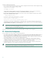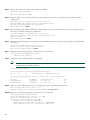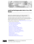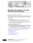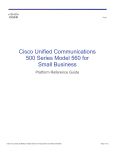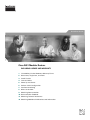
1
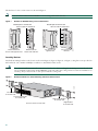
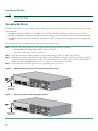
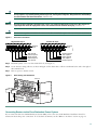
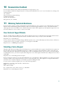
Quick Start Guide
Cisco 2691 Modular Routers
INCLUDING LICENSE AND WARRANTY
1
Cisco 90-Day Limited Hardware Warranty Terms
2
Documents, Equipment, and Tools
3
Install Chassis
4
Connect Cables
5
Power Up the Router
6
Perform Initial Configuration
7
Interface Numbering
8
Where to Go Next
9
Obtaining Documentation
10 Documentation Feedback
11 Obtaining Technical Assistance
12 Obtaining Additional Publications and Information
1 Cisco 90-Day Limited Hardware Warranty Terms
There are special terms applicable to your hardware warranty and various services that you can use during the warranty period.
Your formal Warranty Statement, including the warranties and license agreements applicable to Cisco software, is available on
Cisco.com. Follow these steps to access and download the Cisco Information Packet and your warranty and license agreements
from Cisco.com.
1. Launch your browser, and go to this URL:
http://www.cisco.com/univercd/cc/td/doc/es_inpck/cetrans.htm
The Warranties and License Agreements page appears.
2. To read the Cisco Information Packet, follow these steps:
a. Click the Information Packet Number field, and make sure that the part number 78-5235-03A0 is highlighted.
b. Select the language in which you would like to read the document.
c. Click Go. The Cisco Limited Warranty and Software License page from the Information Packet appears.
d. Read the document online, or click the PDF icon to download and print the document in Adobe Portable Document
Format (PDF).
Note
You must have Adobe Acrobat Reader to view and print PDF files. You can download the reader from Adobe’s
website: http://www.adobe.com
3. To read translated and localized warranty information about your product, follow these steps:
a. Enter this part number in the Warranty Document Number field: 78-5236-01C0
b. Select the language in which you would like to read the document.
c. Click Go. The Cisco warranty page appears.
d. Review the document online, or click the PDF icon to download and print the document in Adobe Portable Document
Format (PDF).
You can also contact the Cisco service and support website for assistance:
http://www.cisco.com/public/Support_root.shtml.
Duration of Hardware Warranty
Ninety (90) days.
Replacement, Repair, or Refund Policy for Hardware
Cisco or its service center will use commercially reasonable efforts to ship a replacement part within ten (10) working days after
receipt of a Return Materials Authorization (RMA) request. Actual delivery times can vary, depending on the customer location.
Cisco reserves the right to refund the purchase price as its exclusive warranty remedy.
To Receive a Return Materials Authorization (RMA) Number
Contact the company from whom you purchased the product. If you purchased the product directly from Cisco, contact your Cisco
Sales and Service Representative.
Complete the information below, and keep it for reference:
Company product purchased from
Company telephone number
Product model number
Product serial number
Maintenance contract number
2
2 Documents, Equipment, and Tools
User Documentation
All the documents referenced in this quick start guide are available online on Cisco.com. To be sure of obtaining the latest
information, you should access the online documentation.
To view or print a document in its original page format, access the online document, and click the PDF icon.
For information about accessing user documentation, see the “Where to Go Next” section on page 23.
Items Included with Cisco 2691 Routers
• Rack-mount brackets with screws for 19-inch rack
• Ground lug; power cord
• RJ-45-to-DB-9 adapter cable for console connection
• RJ-45-to-DB-25 adapter cable for modem connection
• Ethernet cable for LAN interface
• Cisco Information Packet
• Cisco 90 Day Limited Hardware Warranty Terms
• Cisco 2600 Series, Cisco 3600 Series, and Cisco 3700 Series Regulatory Compliance and Safety Information document
• Cisco Security Device Manager (SDM) Quick Start Guide document (if VPN bundle is installed on your router)
• Cisco 2691 Modular Routers Quick Start Guide (this document)
Items Not Included
Individual items in this list may be required for your particular application:
• Four screws for installing the chassis in a rack
• PC running terminal emulation software for administrative access, or modem for remote administrative access
• Cables for WAN interfaces, voice interfaces, or additional LAN interfaces
• Cable ties
• Number 2 Phillips screwdriver
3 Install Chassis
Safety Information
For safety information you need to know before working on your Cisco router, refer to the Cisco 2600 Series, Cisco 3600 Series,
and Cisco 3700 Series Regulatory Compliance and Safety Information document that accompanied this device.
Note
To see translations of the warnings that appear in this publication, refer to the Cisco 2600 Series, Cisco 3600 Series,
and Cisco 3700 Series Regulatory Compliance and Safety Information document.
3
Warning Definition
IMPORTANT SAFETY INSTRUCTIONS
Warning
This warning symbol means danger. You are in a situation that could cause bodily injury. Before you
work on any equipment, be aware of the hazards involved with electrical circuitry and be familiar with
standard practices for preventing accidents. To see translations of the warnings that appear in this
publication, refer to the translated safety warnings that accompanied this device. Statement 1071
SAVE THESE INSTRUCTIONS
Waarschuwing
BELANGRIJKE VEILIGHEIDSINSTRUCTIES
Dit waarschuwingssymbool betekent gevaar. U verkeert in een situatie die lichamelijk letsel kan
veroorzaken. Voordat u aan enige apparatuur gaat werken, dient u zich bewust te zijn van de bij
elektrische schakelingen betrokken risico's en dient u op de hoogte te zijn van de standaard praktijken
om ongelukken te voorkomen. Voor een vertaling van de waarschuwingen die in deze publicatie
verschijnen, dient u de vertaalde veiligheidswaarschuwingen te raadplegen die bij dit apparaat
worden geleverd.
Opmerking BEWAAR DEZE INSTRUCTIES.
Varoitus
TÄRKEITÄ TURVALLISUUTEEN LIITTYVIÄ OHJEITA
Tämä varoitusmerkki merkitsee vaaraa. Olet tilanteessa, joka voi johtaa ruumiinvammaan. Ennen kuin
työskentelet minkään laitteiston parissa, ota selvää sähkökytkentöihin liittyvistä vaaroista ja
tavanomaisista onnettomuuksien ehkäisykeinoista. Tässä asiakirjassa esitettyjen varoitusten
käännökset löydät laitteen mukana toimitetuista ohjeista.
Huomautus SÄILYTÄ NÄMÄ OHJEET
Attention
IMPORTANTES INFORMATIONS DE SÉCURITÉ
Ce symbole d'avertissement indique un danger. Vous vous trouvez dans une situation pouvant causer
des blessures ou des dommages corporels. Avant de travailler sur un équipement, soyez conscient des
dangers posés par les circuits électriques et familiarisez-vous avec les procédures couramment
utilisées pour éviter les accidents. Pour prendre connaissance des traductions d'avertissements
figurant dans cette publication, consultez les consignes de sécurité traduites qui accompagnent cet
appareil.
Remarque CONSERVEZ CES INFORMATIONS
Warnung
WICHTIGE SICHERHEITSANWEISUNGEN
Dieses Warnsymbol bedeutet Gefahr. Sie befinden sich in einer Situation, die zu einer Körperverletzung
führen könnte. Bevor Sie mit der Arbeit an irgendeinem Gerät beginnen, seien Sie sich der mit
elektrischen Stromkreisen verbundenen Gefahren und der Standardpraktiken zur Vermeidung von
Unfällen bewusst. Übersetzungen der in dieser Veröffentlichung enthaltenen Warnhinweise sind im
Lieferumfang des Geräts enthalten.
Hinweis BEWAHREN SIE DIESE SICHERHEITSANWEISUNGEN AUF
4
Avvertenza
IMPORTANTI ISTRUZIONI SULLA SICUREZZA
Questo simbolo di avvertenza indica un pericolo. La situazione potrebbe causare infortuni alle persone.
Prima di intervenire su qualsiasi apparecchiatura, occorre essere al corrente dei pericoli relativi ai
circuiti elettrici e conoscere le procedure standard per la prevenzione di incidenti. Per le traduzioni
delle avvertenze riportate in questo documento, vedere le avvertenze di sicurezza che accompagnano
questo dispositivo.
Nota CONSERVARE QUESTE ISTRUZIONI
Advarsel
VIKTIGE SIKKERHETSINSTRUKSJONER
Dette varselssymbolet betyr fare. Du befinner deg i en situasjon som kan forårsake personskade. Før
du utfører arbeid med utstyret, bør du være oppmerksom på farene som er forbundet med elektriske
kretssystemer, og du bør være kjent med vanlig praksis for å unngå ulykker. For å se oversettelser av
advarslene i denne publikasjonen, se de oversatte sikkerhetsvarslene som følger med denne enheten.
Merk TA VARE PÅ DISSE INSTRUKSJONENE
Aviso
INSTRUÇÕES IMPORTANTES DE SEGURANÇA
Este símbolo de aviso significa perigo. O utilizador encontra-se numa situação que poderá ser
causadora de lesões corporais. Antes de iniciar a utilização de qualquer equipamento, tenha em
atenção os perigos envolvidos no manuseamento de circuitos eléctricos e familiarize-se com as
práticas habituais de prevenção de acidentes. Para ver traduções dos avisos incluídos nesta
publicação, consulte os avisos de segurança traduzidos que acompanham este dispositivo.
Nota GUARDE ESTAS INSTRUÇÕES
¡Advertencia!
INSTRUCCIONES IMPORTANTES DE SEGURIDAD
Este símbolo de aviso indica peligro. Existe riesgo para su integridad física. Antes de manipular
cualquier equipo, considere los riesgos de la corriente eléctrica y familiarícese con los
procedimientos estándar de prevención de accidentes. Vea las traducciones de las advertencias que
acompañan a este dispositivo.
Nota GUARDE ESTAS INSTRUCCIONES
Varning!
VIKTIGA SÄKERHETSANVISNINGAR
Denna varningssignal signalerar fara. Du befinner dig i en situation som kan leda till personskada.
Innan du utför arbete på någon utrustning måste du vara medveten om farorna med elkretsar och känna
till vanliga förfaranden för att förebygga olyckor. Se översättningarna av de varningsmeddelanden som
finns i denna publikation, och se de översatta säkerhetsvarningarna som medföljer denna anordning.
OBS! SPARA DESSA ANVISNINGAR
5
Aviso
INSTRUÇÕES IMPORTANTES DE SEGURANÇA
Este símbolo de aviso significa perigo. Você se encontra em uma situação em que há risco de lesões
corporais. Antes de trabalhar com qualquer equipamento, esteja ciente dos riscos que envolvem os
circuitos elétricos e familiarize-se com as práticas padrão de prevenção de acidentes. Use o número
da declaração fornecido ao final de cada aviso para localizar sua tradução nos avisos de segurança
traduzidos que acompanham o dispositivo.
GUARDE ESTAS INSTRUÇÕES
6
Advarsel
VIGTIGE SIKKERHEDSANVISNINGER
Dette advarselssymbol betyder fare. Du befinder dig i en situation med risiko for legemesbeskadigelse.
Før du begynder arbejde på udstyr, skal du være opmærksom på de involverede risici, der er ved
elektriske kredsløb, og du skal sætte dig ind i standardprocedurer til undgåelse af ulykker. Brug
erklæringsnummeret efter hver advarsel for at finde oversættelsen i de oversatte advarsler, der fulgte
med denne enhed.
GEM DISSE ANVISNINGER
7
Warning
This unit is intended for installation in restricted access areas. A restricted access area can be accessed only
through the use of a special tool, lock and key, or other means of security. Statement 1017
Warning
Before working on equipment that is connected to power lines, remove jewelry (including rings, necklaces, and
watches). Metal objects will heat up when connected to power and ground and can cause serious burns or weld
the metal object to the terminals. Statement 43
Warning
This equipment has been designed for connection to TN and IT power systems. Statement 1007
8
Warning
To avoid electric shock, do not connect safety extra-low voltage (SELV) circuits to telephone-network voltage
(TNV) circuits. LAN ports contain SELV circuits, and WAN ports contain TNV circuits. Some LAN and WAN ports
both use RJ-45 connectors. Use caution when connecting cables. Statement 1021
Warning
This equipment must be grounded. Never defeat the ground conductor or operate the equipment in the absence of
a suitably installed ground conductor. Contact the appropriate electrical inspection authority or an electrician if
you are uncertain that suitable grounding is available. Statement 1024
Warning
Blank faceplates and cover panels serve three important functions: they prevent exposure to hazardous voltages
and currents inside the chassis; they contain electromagnetic interference (EMI) that might disrupt other
equipment; and they direct the flow of cooling air through the chassis. Do not operate the system unless all cards,
faceplates, front covers, and rear covers are in place. Statement 1029
Warning
Only trained and qualified personnel should be allowed to install, replace, or service this equipment.
Statement 1030
Warning
To prevent personal injury or damage to the chassis, never attempt to lift or tilt the chassis using the handles on
modules (such as power supplies, fans, or cards); these types of handles are not designed to support the weight
of the unit. Statement 1032
Warning
Ultimate disposal of this product should be handled according to all national laws and regulations. Statement 1040
Installing the Chassis
You can set the chassis on a desktop or install it in a rack. See the applicable instructions in the following sections:
• Rack-Mounting the Chassis, page 9
• Installing on Desktop, page 12
Note
Caution
Cisco 2691 routers are not designed for wall-mounting.
To prevent damage to the chassis, never attempt to lift or tilt the chassis by the plastic panel on the front. Always
hold the chassis by the metal body.
Rack-Mounting the Chassis
Cisco 2691 routers can be installed in 19- or 23-inch racks with the following chassis orientations:
• Center mounting—Brackets attached in the center of the chassis with either front panel or rear panel facing forward
• Front mounting—Brackets attached at the front of the chassis with the front panel facing forward
• Rear mounting—Brackets attached at the rear of the chassis with the rear panel facing forward
9
The brackets for Cisco 2691 routers are shown in Figure 1.
The slots in the brackets marked RIGHT are for securing cables with cable ties.
Brackets for Rack-Mounting of Cisco 2691 Routers
Bracket pair for 19-inch rack
Bracket pair for 23-inch rack
Slots for cable tie attachment
Slots for cable tie attachment
RIGHT
23" ETSI, NEBS
LEFT
LEFT
Narrow bracket for
chassis side opposite fans
For chassis side
with fans
For chassis side
opposite fans
Wide bracket for
chassis side with fans
88810
Figure 1
23" ETSI, NEBS
RIGHT
Note
Attaching Brackets
Attach the mounting brackets to the chassis as shown in Figure 2, Figure 3, Figure 4, or Figure 5, using the screws provided in
the bracket kit. Use a number 2 Phillips screwdriver to install the bracket screws.
Caution
Your chassis installation must allow unrestricted airflow for chassis cooling. For mounting in a 19-inch rack, be
sure to install the wide bracket (marked RIGHT) on the side where the cooling fans are located. For installation on
a desktop, keep at least 1 inch of clear space beside the cooling fans.
Figure 2
Bracket Installation for Center Mounting with Front Panel Forward
Use two screws on each side.
10
23" ETSI, NEBS
RIGHT
RIGHT
82689
LEFT
23" ETSI, NEBS
LEFT
SERIES
SER
IES
Left bracket
for 23-inch rack
Left (narrow) bracket
for 19-inch rack
Right (wide) bracket
for 19-inch rack
Right bracket
for 23-inch rack
Bracket Installation for Center Mounting with Rear Panel Forward
RIGHT
RIGHT
82690
Figure 3
NM-HDV
SEE
MANUAL
BEFORE
INSTALL
ATION
SEE MANUAL
BEFORE
INSTALL
ATION
DSU
56K
SEE MANUAL
BEFORE
INSTALL
ATION
Left (narrow) bracket
for 19-inch rack
Left bracket
for 23-inch rack
Use two screws on each side.
Bracket Installation for Front Mounting
LEFT
23" ETSI, NEBS
LEFT
82691
Figure 4
LEFT
LEFT
DSU
56K
RD
INSTALL
ATION
LP
BEFORE
CD
SEE MANUAL
AL
V0
EN
TD
CD
E1
TD
CTRLR
RD
CD
E2
LP
LP
CTRLR
AL
AL
VWIC
BANK 4
2MFT-E
1
BANK 3
BANK 2
BANK 1
BANK 0
Right bracket
for 23-inch rack
Right (wide) bracket
for 19-inch rack
SERIES
SER
IES
23" ETSI, NEBS
RIGHT
RIGHT
Left bracket
for 23-inch rack
Left (narrow) bracket
for 19-inch rack
Right (wide) bracket
for 19-inch rack
Right bracket
Use two screws on each side.
for 23-inch rack
Bracket Installation for Rear Mounting
RIGHT
23" ETSI, NEBS
RIGHT
82692
Figure 5
NM-HDV
SEE
MANUA
L
BEFOR
E
INSTAL
LATION
SEE MANUA
L BEFOR
E INSTAL
LATION
DSU
56K
SEE MANUA
L BEFOR
E INSTAL
LATION
LEFT
DSU
56K
CD
LATION
TD
E INSTAL
RD
L BEFOR
23" ETSI, NEBS
LEFT
Right (wide) bracket
for 19-inch rack
SEE MANUA
LP
V0
EN
Right bracket
for 23-inch rack
AL
CD
E1
TD
CTRLR
RD
CD
E2
LP
LP
CTRLR
AL
AL
VWIC
BANK 4
2MFT-E1
BANK 3
BANK 2
BANK 1
BANK 0
Left (narrow) bracket
for 19-inch rack
Left bracket
Four screws are required on each side.
for 23-inch rack
Installing Chassis in Rack
Install the chassis in the rack. Rack-mounting screws are not provided with the router. Use two screws for each side (supplied
with the rack).
11
Installing on Desktop
Caution
If you place the Cisco router on a desktop, do not place anything that weighs more than 10 pounds (4.5 kilograms)
on top of the chassis.
Grounding the Chassis
You must connect the chassis to a reliable earth ground; the ground wire must be installed in accordance with local electrical
safety standards.
• For NEBS-compliant grounding, use size AWG 6 (13 mm2) wire and the ground lug provided in the accessory kit.
• For NEC-compliant grounding, use size AWG 14 (2 mm2) or larger wire and an appropriate user-supplied ring terminal.
• For EN/IEC 60950-compliant grounding, use size AWG 18 (1 mm2) or larger wire and an appropriate user-supplied ring
terminal.
To connect the chassis to a reliable earth ground, perform the following steps:
Step 1
Strip one end of the ground wire to the length required for the ground lug or terminal.
• For the NEBS ground lug—approximately 0.75 in. (20 mm)
• For user-provided ring terminal—as required
Step 2
Crimp the ground wire to the ground lug or ring terminal, using a crimp tool of the appropriate size.
Step 3
Attach the ground lug or ring terminal to the chassis as shown in Figure 6 or Figure 7. For the ground lug, use the two
screws with captive locking washers provided. For a ring terminal, use one of the screws provided. Use a number 2
Phillips screwdriver, and tighten the screws to a torque of 8 to 10 in-lb (0.9 to 1.1 N-m).
Step 4
Connect the other end of the ground wire to a grounding point at your site.
NEBS-Compliant Chassis Ground Connection Using Ground Lug
72228
Figure 6
ASYNC
31
30
27
29
26
28
25
ASYNC
24-31
24
23
15
14
11
13
10
12
9
22
19
21
18
20
17
ASYNC
8-15
ASYNC
16-23
16
8
ASYNC
0-7
DSU
56K
CD
LLATION
TD
RE INSTA
ACT
100 Mbps
SEE MANU
AL BEFO
LINK
ACT
FAST ETHER
NET 0/1
Ground lug
attachment
CF1
RE INSTA
DSU
56K
LLATION
100 Mbps
LINK
FAST ETHER
NET 0/0
SEE MANU
AL BEFO
RE INSTA
LLATION
CISCO269
1
CONSO
LE
AUX
Chassis Ground Connection Using Ring Terminal
103008
Figure 7
RD
SEE MANU
AL BEFO
EN
LP
0
AL
CD
1
TD
2
4
RD
3
5
LP
6
AL
7
ASYNC
31
30
27
29
26
28
25
ASYNC
24-31
24
23
15
14
11
13
10
12
9
ASYNC
22
19
21
18
20
17
ASYNC
16-23
16
8-15
8
ASYNC
0-7
CD
TD
DSU
56K
ACT
100 Mbps
LINK
ACT
FAST ETHER
NET 0/1
Ring terminal
attachment
12
RD
SEE MANU
AL BEFO
RE INSTA
LLATION
EN
LP
0
AL
CD
1
TD
2
4
RD
3
5
LP
6
AL
7
SEE MANU
AL BEFO
RE INSTA
CF1
LLATION
DSU
56K
100 Mbps
FAST ETHER
NET 0/0
LINK
SEE MANU
AL BEFO
RE INSTA
LLATION
CISCO269
1
CONSO
LE
AUX
4 Connect Cables
Warning
Do not work on the system, or connect or disconnect cables during periods of lightning activity. Statement 1001
System Management Connections
The connections described in Table 1 provide system management access.
Table 1
System Management Connections
Port
Color
Connected To:
Console
Light blue PC or ASCII terminal communication port (usually labeled COM) RJ-45-to-DB-9 adapter cable
Auxiliary
Black
Modem for remote access
Cable
RJ-45-to-DB-25 adapter cable
Power Connections
Warning
Note
Read the installation instructions before connecting the system to the power source. Statement 1004
The installation must comply with all required electrical codes applicable at the installation site.
Connecting Routers to AC Power
If your router uses AC power, connect it to a 15 A, 120 VAC (10 A, 240 VAC) circuit with overcurrent protection.
Note
The input voltage tolerance limits for AC power are 85 and 264 VAC.
Warning
AC connected units must have a permanent ground connection in addition to the power cable ground wire.
NEBS-compliant grounding satisfies this requirement. Statement 284
Warning
This product relies on the building’s installation for short-circuit (overcurrent) protection. Ensure that the
protective device is rated not greater than:
15A, 120VAC (10A, 240VAC). Statement 1005
Connecting the Router to DC Power
If your router has a DC-input power supply, follow the directions in this section for proper wiring.
Warning
This product relies on the building’s installation for short-circuit (overcurrent) protection. Ensure that the
protective device is rated not greater than:
15A, 60VDC. Statement 1005
Warning
Use copper conductors only. Statement 1025
13
Caution
If you connect dual DC power sources, both sources must be the same polarity. Do not connect a –DC with a +DC
source to a Cisco 2691 router. Opposite-polarity sources damage the power supply.
DC Wiring Requirements
A Cisco 2691 router with a DC-input power supply requires copper wire for the power connections. Table 2 summarizes the
wiring requirements.
You can connect a single DC power source to either the A input or the B input. If there are dual power sources, connect one
source to the A input and one source to the B input; both sources must be the same polarity and voltage.
Note
Table 2
For installations compliant with the National Electric Code, AWG 14 (2.0 mm2) wire is required for DC input and
safety ground wire.
DC Wiring Requirements for Cisco 2691 Routers
Installed Power Supply
DC Input
DC Input
Wire Size1
Safety Ground
Wire Size
Overcurrent
Protection
Nominal 24/48 VDC2
24 - 36 V, 8 A, positive or negative,
single or dual sources
AWG 18
(1.0 mm2)
AWG 14
(2.0 mm2)
15 A maximum
36 - 60 V, 4 A, positive or negative,
single or dual sources
AWG 18
(1.0 mm2)
AWG 14
(2.0 mm2))
15 A maximum
1. See the note above this table for National Electric Code wire size requirements.
2. The input voltage tolerance limits for nominal 24/48 V power supplies are 18 and 72 VDC.
Wiring Procedure for DC Input
To connect the router to a DC power source, perform the following steps:
Step 1
Warning
Remove power from the DC circuit. To ensure that power is removed from the DC circuit, locate the circuit breaker for
the DC circuit, switch the circuit breaker to the OFF position, and tape the circuit-breaker switch in the OFF position.
Before performing any of the following procedures, ensure that power is removed from the DC circuit.
Statement 1003
Tip
Secure all power cabling when installing this unit to avoid disturbing field-wiring connections.
Step 2
Strip the wires to the appropriate length for the terminals. The strip length is 3/16 in. to 1/4 in. (5 mm to 7 mm).
Step 3
Remove the plastic covers from the terminal block. Save them for reinstallation after you finish wiring.
Note
Step 4
14
Do not remove the colored screw at either end of the terminal block. Those are the terminal mounting screws.
Connect the wires to the terminal block, starting with the safety ground wire. Insert each wire into the appropriate
terminal as shown in Figure 8. To avoid interference with the on/off switch, insert the wires from below. Tighten the
terminal screws to 8.0 ± 0.5 in-lb (0.9 ± 0.05 N-m).
Warning
The illustration shows the DC power supply terminal block. Wire the DC power supply as illustrated. The proper
wiring sequence is ground to ground, positive to positive, and negative to negative. The ground wire should always
be connected first and disconnected last. Statement 239
Warning
An exposed wire lead from a DC-input power source can conduct harmful levels of electricity. Be sure that no
exposed portion of the DC-input power source wire extends from the terminal block plug. Statement 122
Caution
Do not overtorque the terminal block contact screws. Recommended torque is 8.0 ± 0.5 in-lb (0.9 ± 0.05 N-m).
Figure 8
DC Power Connections
Positive DC input
Terminal
block
A +
Terminal
block
A +
+ B
95965
Negative DC output
+ B
-DC, input B
Return, input B
Safety ground
Return, input A
-DC, input A
Return, input B
+DC, input B
Safety ground
+DC, input A
Return, input A
Step 5
Install the plastic covers over the terminal block. (See Figure 9.)
Step 6
Secure the wires using cable ties as shown in Figure 9. The chassis has a cable-tie attachment below and to the right of
the terminal block.
Step 7
Turn on power to the DC circuit.
Figure 9
Wire Routing and Attachment
AL
From DC
power
source
CD
TD
RD
LP
Cable tie
SEE MA
NUAL BE
FO
RE INSTAL
LATION
DSU
56K
NUAL BE
FO
RE INSTAL
LATION
95824
SEE MA
Plastic covers
Connecting Routers to the Cisco Redundant Power System
If your router uses the Cisco Redundant Power System (RPS), refer to the Cisco RPS Hardware Installation Guide for
instructions about the power connections. To locate these documents, see the “Where to Go Next” section on page 23.
15
WAN, LAN, and Voice Connections
The connections and cables listed here are described in detail in the following documents:
• Cisco 2600 Series Hardware Installation Guide
• Cisco Network Modules Hardware Installation Guide
• Cisco Interface Cards Installation Guide
• Cisco Modular Access Router Cable Specifications
To locate these documents, see the “Where to Go Next” section on page 23.
Table 3 summarizes some typical WAN, LAN, and voice connections for the Cisco 2691 routers.
Table 3
WAN, LAN, and Voice Connections
Port or Connection
Port Type, Color
Connected To:
Cable
Ethernet
RJ-45, yellow
Ethernet hub or Ethernet switch
Straight-through Ethernet
T1/E1 WAN
RJ-48C/CA81A, blue
T1 or E1 network
RJ-48 T1
Cisco serial
60-pin D-sub
CSU/DSU and serial network or
equipment
Cisco Smart serial
Cisco Smart compact
connector, blue
CSU/DSU and serial network or
equipment (For WIC-2T and
WIC-2A/S only)
Cisco serial transition cable that matches
the signaling protocol (EIA/TIA-232,
EIA/TIA-449, V.35, X.21, or EIA-530)
and the serial port operating mode (DTE
or DCE).1
DSL
RJ-11C/CA11A,
lavender
Network demarcation device for
service provider’s DSL interface
RJ-11
T1 digital voice
RJ-48C/CA81A, tan
Digital PBX
RJ-48 T1 cable
Analog voice FXS
RJ-11, gray
Telephone, fax
RJ-11
Analog voice FXO
RJ-11, pink
Central office, analog PBX
RJ-11
Analog voice E&M
RJ-11, brown
Analog PBX
RJ-11
BRI S/T WAN
(external NT1)
RJ-48C/CA81A, orange NT1 device or private integrated
network exchange (PINX)
RJ-48
BRI U WAN
(built-in NT1)
RJ-49C/CA-A11, red
ISDN network
RJ-49
CT1/PRI
T1
External T1 CSU
DB-15 T1 serial cable
CT1/PRI-CSU
T1
RJ-48C/CA81A interface
RJ-48 straight-through
CE1/PRI
E1
E1 network
DB-15 to BNC, DB-15 to DB-15,
DB-15 to twinax, or DB-15 to RJ-45
Token Ring
UTP, purple
Token Ring device
RJ-45 Token Ring cable
RJ-48S interface
RJ-48 straight-through
STP, purple
56/64-kbps DSU/CSU 8-pin modular, blue
1. See the Cisco Modular Access Router Cable Specifications document for information about selecting these cables.
16
5 Power Up the Router
Checklist for Power-Up
You are ready to power up the Cisco router after the following steps are completed:
• Chassis is securely mounted and grounded.
• Power and interface cables are connected.
• Your PC terminal emulation program is configured for 9600 baud, 8 data bits, 1 stop bit, and no parity.
• You have selected passwords for access control.
• You have determined the IP addresses for the Ethernet and serial interfaces.
Front Panel Indicators
The following indicator LEDs provide power, activity, and status information:
• PWR (green)—Lit when power is on
• SYS/RPS or RPS (green)
– Rapid blinking (200 ms)—System is booting
– Slow blinking (1 s)—Redundant power supply (RPS) failure
– Continuous on—System OK
• ACT (green)—Blinks during system activity, such as interrupts and packet transfers
Power-Up Procedure
To power up your Cisco router and verify that it goes through its initialization and self-test, perform this procedure. When the
procedure is finished, the Cisco router is ready to be configured.
Note
To view the boot sequence through a terminal session, you must have a console connection to the Cisco router before
it powers on.
Step 1
Make sure that your PC is powered up and connected as described in the “Checklist for Power-Up” section.
Step 2
Move the power switch to the ON position.
The green POWER or PWR LED on the front of the chassis comes on and the fan operates. If this does not happen, see
the power-up procedure in the Cisco 2600 Series Routers Hardware Installation Guide.
Messages begin to appear in your terminal emulation program window.
Caution
Do not press any keys on the keyboard until the messages stop. Any keys pressed during this time are interpreted
as the first command typed when the messages stop, which might cause the router to power off and start over. It
takes a few minutes for the messages to stop.
17
You may see different startup messages:
• If you see the following messages, the router has booted with a configuration file and is ready for initial configuration using
the Cisco Router and Security Device Manager (SDM):
yourname con0 is now available
Press RETURN to get started.
See the “Initial Configuration Using Cisco Router and Security Device Manager” section on page 19 to learn how to
configure your router using SDM or to learn how to obtain SDM and install it on your router.
• If you see the following messages, the router has booted and is ready for initial configuration using the setup command
facility or the command-line interface (CLI).
--- System Configuration Dialog --At any point you may enter a question mark '?' for help.
Use ctrl-c to abort configuration dialog at any prompt.
Default settings are in square brackets '[]'.
Would you like to enter the initial configuration dialog? [yes/no]:
To learn how to use the setup command facility to configure the router, see the “Initial Configuration Using the Setup
Command Facility” section on page 19. To learn how to use the CLI to configure the router, see the “Initial Configuration
Using the CLI (Manual Configuration)” section on page 21.
Note
If the rommon 1> prompt appears, your system has booted in ROM monitor mode. For information on the ROM
monitor, see the router rebooting and ROM monitor information in the Cisco IOS Configuration Fundamentals
Configuration Guide for your Cisco IOS software release.
You can access this document at the locations described in the “Where to Go Next” section on page 23.
6 Perform Initial Configuration
You can configure your router by using one of the following methods:
• Cisco Router and Security Device Manager (SDM)—If your router was purchased with a VPN bundle, SDM is installed on
the router. For instructions on configuring your router by using SDM, refer to the Cisco Router and Security Device
Manager (SDM) Quick Start Guide that shipped with your router. See the “Initial Configuration Using Cisco Router and
Security Device Manager” section on page 19 for additional information.
• Setup command facility—You can use the setup command facility to configure basic router information. After the
configuration file has been created, you can use the CLI or SDM to perform additional configuration. See the “Initial
Configuration Using the Setup Command Facility” section on page 19 for additional information.
• Command-line interface (CLI)—If you prefer to use the Cisco IOS CLI, see the “Initial Configuration Using the CLI
(Manual Configuration)” section on page 21 for instructions on how to use the CLI.
Note
18
You need to understand how interfaces are numbered so that you know which interface you are configuring. If you need
help with interface and port numbering, see the “Interface Numbering” section on page 22.
Initial Configuration Using Cisco Router and Security Device Manager
If the following messages appear at the end of the startup sequence, Cisco Router and Security Device Manager (SDM) is
installed on your router:
yourname con0 is now available
Press RETURN to get started.
For instructions on configuring your router by using SDM, refer to the Cisco Router and Security Device Manager (SDM) Quick
Start Guide.
Tip
If the messages above do not appear, SDM and the Cisco Router and Security Device Manager (SDM) Quick Start Guide
were not shipped with your router. If you want to use SDM, you can download the latest version of SDM and
instructions for installing it on your router from the following location:
http://www.cisco.com/pcgi-bin/tablebuild.pl/sdm
To obtain the SDM quick start guide, SDM release notes, and other SDM documentation, go to www.cisco.com/go/sdm
and click the Technical Documentation link.
Initial Configuration Using the Setup Command Facility
This section shows how to use the setup command facility to configure a host name for the router, set passwords, and configure
an interface for communication with the management network. If you see the following messages at the end of the startup
sequence, the setup command facility has been invoked automatically:
--- System Configuration Dialog --At any point you may enter a question mark '?' for help.
Use ctrl-c to abort configuration dialog at any prompt.
Default settings are in square brackets '[]'.
Would you like to enter the initial configuration dialog? [yes/no]:
The setup command facility prompts you for basic information about your router and network, and it creates an initial
configuration file.The prompts vary, depending on your router model, the installed interface modules, and the software image.
The following example and the user entries (in bold) are shown as examples only.
For interface numbering information, see the “Interface Numbering” section on page 22.
Note
If you make a mistake while using the setup command facility, you can exit and run the setup command facility again.
Press Ctrl-C, and enter setup at the privileged EXEC mode prompt (2691#).
Step 1
To proceed using the setup command facility, enter yes.
Would you like to enter the initial configuration dialog? [yes/no]: yes
Step 2
When the following messages appear, press Return to enter basic management setup:
At any point you may enter a question mark '?' for help.
Use ctrl-c to abort configuration dialog at any prompt.
Default settings are in square brackets '[]'.
Basic management setup configures only enough connectivity
for management of the system, extended setup will ask you
to configure each interface on the system
Would you like to enter basic management setup? [yes/no]: yes
19
Step 3
Enter a host name for the router (this example uses 2691):
Configuring global parameters:
Enter host name [Router]: 2691
Step 4
Enter an enable secret password. This password is encrypted (more secure) and cannot be seen when viewing the
configuration:
The enable secret is a password used to protect access to
privileged EXEC and configuration modes. This password, after
entered, becomes encrypted in the configuration.
Enter enable secret: xxxxxx
Step 5
Enter an enable password that is different from the enable secret password. This password is not encrypted (less secure)
and can be seen when viewing the configuration:
The enable password is used when you do not specify an
enable secret password, with some older software versions, and
some boot images.
Enter enable password: xxxxxx
Step 6
Enter the virtual terminal password, which prevents unauthenticated access to the router through ports other than the
console port:
The virtual terminal password is used to protect
access to the router over a network interface.
Enter virtual terminal password: xxxxxx
Step 7
Respond to the following prompts as appropriate for your network:
Configure SNMP Network Management? [yes]:
Community string [public]:
Step 8
A summary of the available interfaces is displayed:
Note
The interface numbering that appears is dependent on the type of Cisco modular router platform and on the
installed interface modules and cards.
Current interface summary
Controller Timeslots D-Channel Configurable modes Status
T1 0/0
24
23
pri/channelized
Administratively up
Any interface listed with OK? value "NO" does not have a valid configuration
Interface
FastEthernet0/0
FastEthernet0/1
Step 9
IP-Address
unassigned
unassigned
OK? Method Status
NO unset up
NO unset up
Select one of the available interfaces for connecting the router to the management network:
Enter interface name used to connect to the
management network from the above interface summary: fastethernet0/0
Step 10 Respond to the following prompts as appropriate for your network:
Configuring interface FastEthernet0/0:
Use the 100 Base-TX (RJ-45) connector? [yes]: yes
Operate in full-duplex mode? [no]: no
Configure IP on this interface? [yes]: yes
IP address for this interface: 172.1.2.3
Subnet mask for this interface [255.255.0.0] : 255.255.0.0
Class B network is 172.1.0.0, 16 subnet bits; mask is /16
20
Prol
up
dow
Step 11 The configuration is displayed:
The following configuration command script was created:
hostname 2691
enable secret 5 $1$D5P6$PYx41/lQIASK.HcSbfO5q1
enable password xxxxxx
line vty 0 4
password xxxxxx
snmp-server community public
!
no ip routing
!
interface FastEthernet0/0
no shutdown
media-type 100BaseX
half-duplex
ip address 172.1.2.3 255.255.0.0
!
interface FastEthernet0/1
shutdown
no ip address
!
end
Step 12 Respond to the following prompts. Select [2] to save the initial configuration.:
[0] Go to the IOS command prompt without saving this config.
[1] Return back to the setup without saving this config.
[2] Save this configuration to nvram and exit.
Enter your selection [2]: 2
Building configuration...
Use the enabled mode 'configure' command to modify this configuration.
Press RETURN to get started! RETURN
Step 13 The user prompt appears.
2691>
After you complete the initial configuration tasks, your Cisco router is ready to configure for specific functions. See the “Where
to Go Next” section on page 23 for information about locating documentation for advanced configuration procedures.
Initial Configuration Using the CLI (Manual Configuration)
This section shows how to bring up a command-line interface (CLI) prompt for configuration using the CLI, and it directs you
to documentation for the CLI configuration.You can use the CLI if you see the following messages at the end of the startup
sequence:
--- System Configuration Dialog --At any point you may enter a question mark '?' for help.
Use ctrl-c to abort configuration dialog at any prompt.
Default settings are in square brackets '[]'.
Would you like to enter the initial configuration dialog? [yes/no]:
If these messages do not appear, SDM and a default configuration file have been installed on the router at the factory. To use
SDM to configure the router, see the “Initial Configuration Using Cisco Router and Security Device Manager” section on
page 19.
21
For interface numbering information, see the “Interface Numbering” section on page 22.
Step 1
To proceed with manual configuration using the CLI, enter no.
Would you like to enter the initial configuration dialog? [yes/no]: no
Step 2
Press Return to terminate autoinstall and continue with manual configuration.
Would you like to terminate autoinstall? [yes] Return
Several messages are displayed, ending with a line similar to the following:
...
Copyright (c) 1986-2000 by cisco Systems, Inc.
Compiled <date> <time> by <person>
Step 3
Press Return to bring up the Router> prompt.
...
flashfs[4]: Initialization complete.
Router>
Step 4
Enter privileged EXEC mode.
Router> enable
Router#
Note
To avoid losing work you have completed, be sure to save your configuration occasionally as you proceed. Use the
copy running-config startup-config command to save the configuration to NVRAM.
For configuration using the CLI, refer to the applicable configuration procedures in the Software Configuration Guide:
Cisco 2600 Series, Cisco 3600 Series, and Cisco 3700 Series Routers. See the “Where to Go Next” section on page 23 for
information about accessing this document.
7 Interface Numbering
Each individual interface (port) on a Cisco 2691 router is identified by number as described in the following sections.
WAN and LAN Interface Numbering
The Cisco 2691 router chassis contains the following WAN and LAN interface types:
• Built-in LAN interfaces: Ethernet, Fast Ethernet, Token Ring
• Two or three slots in which you can install WAN interface cards (WICs)
• One slot in which you can install a network module
The numbering format is Interface-type Slot-number/Interface-number. Two examples are:
• Ethernet 0/0
• Serial 1/2
The slot number is 0 for all built-in interfaces and 0 for all WIC interfaces; the slot number is 1 for network module interfaces.
Interface (port) numbers begin at 0 for each interface type, and continue from right to left and (if necessary) from bottom to top.
Figure 10 shows a router with:
• A 2-port T1 network module in slot 1 (containing the following ports: T1 1/0 and T1 1/1)
• Two built-in Ethernet 10/100 interfaces—Fast Ethernet 0/0 and Fast Ethernet 0/1
22
• A WIC in each WIC slot (containing interfaces Serial 0/0 and Serial 0/1 in physical slot W0, interface Serial 0/2 in physical
slot W1, and interface BRI 0/0 in physical slot W2)
– If physical slot W0 is empty and physical slot W1 contains a 1-port serial WIC, the interface number in the WIC is
numbered Serial 0/0.
– If slot W0 contains a 2-port serial WIC and slot W1 contains a 1-port serial WIC, the interfaces in physical slot W0 are
numbered Serial 0/0 and Serial 0/1, and the interface in physical slot W1 is numbered Serial 0/2.
– If slot W0 contains a 2-port serial WIC and slot W1 contains a 1-port BRI WIC, the interfaces in physical slot W0 are
numbered Serial 0/0 and Serial 0/1, and the interface in physical slot W1 is numbered BRI 0/0.
Figure 10
The slot number for all WIC interfaces is always 0. (The W0 and W1 slot designations are for physical slot
identification only.) Interfaces in the WICs are numbered from right to left, starting with 0/0 for each interface type,
regardless of which physical slot the WICs are installed in.
Interface Numbering in Cisco 2691 Routers
62101
Note
NM-HDV
AL
LP
DSU
56K
CD
LLATION
TD
RE INSTA
RD
SEE MANU
AL BEFO
LP
V0
EN
AL
CD
MANUAL
BEFORE
INSTALLAT
ION
TD
CTRLR
E1
RD
SEE
CD
LP
CTRLR
E2
AL
VWIC
BANK 4
2MFT-E1
BANK 3
BANK 2
BANK 1
BANK 0
SEE MANU
AL BEFO
RE INSTA
LLATION
DSU
56K
SEE MANU
AL BEFO
RE INSTA
LLATION
T1 1/1
T1 1/0
FastEthernet 0/1
BRI 0/0
Serial 0/2
Compact Flash slot
FastEthernet 0/0
Serial 0/1
Serial 0/0
Voice Interface Numbering
Voice interfaces are numbered as follows:
chassis-slot/voice-module-slot/voice-interface
If a 4-channel voice network module is installed in chassis slot 1, the voice interfaces are:
• 1/0/0—Chassis slot 1/Voice module slot 0/Voice interface 0
• 1/0/1—Chassis slot 1/Voice module slot 0/Voice interface 1
• 1/1/0—Chassis slot 1/Voice module slot 1/Voice interface 0
• 1/1/1—Chassis slot 1/Voice module slot 1/Voice interface 1
8 Where to Go Next
For additional detailed configuration procedures, refer to the appropriate Cisco 2691 documentation or Cisco IOS software
documentation, available online on Cisco.com:
Tip
See the “Obtaining Documentation” section on page 24 for help in locating these documents.
23
To access documentation on Cisco.com:
For Cisco 2600 series platform documentation, start on Cisco.com at http://www.cisco.com, and select Products & Services >
Routers > Cisco 2600 Series Multiservice Platforms > Technical Documentation > Document type > Document.
For Cisco IOS software documentation, start on Cisco.com at http://www.cisco.com, and select Products & Services > IOS
Software > Cisco IOS Software Releases > Your Cisco IOS software release.
To get updated information about platform support for features, select Feature Navigator II, if you have an account on
Cisco.com. You can also access Feature Navigator II at http://www.cisco.com/go/fn.
To access documentation using Cisco Connection Online (CCO):
For Cisco 3631 platform documentation, start on Cisco.com at http://www.cisco.com, and click on the “Technical
Documentation” tab under Useful Links. Under the Product Documentation heading, navigate to Modular Access Routers and
to the documentation for your router.
For Cisco IOS software documentation, start on Cisco.com at http://www.cisco.com, and click on the “Technical
Documentation” tab under Useful Links. Under the Product Documentation heading, navigate to the Cisco IOS software
documentation for the Cisco IOS software release that is installed on your router.
9 Obtaining Documentation
Cisco documentation and additional literature are available on Cisco.com. Cisco also provides several ways to obtain technical
assistance and other technical resources. These sections explain how to obtain technical information from Cisco Systems.
Cisco.com
You can access the most current Cisco documentation at this URL:
http://www.cisco.com/univercd/home/home.htm
You can access the Cisco website at this URL:
http://www.cisco.com
You can access international Cisco websites at this URL:
http://www.cisco.com/public/countries_languages.shtml
Ordering Documentation
You can find instructions for ordering documentation at this URL:
http://www.cisco.com/univercd/cc/td/doc/es_inpck/pdi.htm
You can order Cisco documentation in these ways:
• Registered Cisco.com users (Cisco direct customers) can order Cisco product documentation from the Ordering tool:
http://www.cisco.com/en/US/partner/ordering/index.shtml
• Nonregistered Cisco.com users can order documentation through a local account representative by calling Cisco Systems
Corporate Headquarters (California, USA) at 408 526-7208 or, elsewhere in North America, by calling 800 553-NETS
(6387).
24
10 Documentation Feedback
You can send comments about technical documentation to [email protected].
You can submit comments by using the response card (if present) behind the front cover of your document or by writing to the
following address:
Cisco Systems
Attn: Customer Document Ordering
170 West Tasman Drive
San Jose, CA 95134-9883
We appreciate your comments.
11 Obtaining Technical Assistance
For all customers, partners, resellers, and distributors who hold valid Cisco service contracts, Cisco Technical Support provides
24-hour-a-day, award-winning technical assistance. The Cisco Technical Support Website on Cisco.com features extensive
online support resources. In addition, Cisco Technical Assistance Center (TAC) engineers provide telephone support. If you do
not hold a valid Cisco service contract, contact your reseller.
Cisco Technical Support Website
The Cisco Technical Support Website provides online documents and tools for troubleshooting and resolving technical issues
with Cisco products and technologies. The website is available 24 hours a day, 365 days a year at this URL:
http://www.cisco.com/techsupport
Access to all tools on the Cisco Technical Support Website requires a Cisco.com user ID and password. If you have a valid service
contract but do not have a user ID or password, you can register at this URL:
http://tools.cisco.com/RPF/register/register.do
Submitting a Service Request
Using the online TAC Service Request Tool is the fastest way to open S3 and S4 service requests. (S3 and S4 service requests are
those in which your network is minimally impaired or for which you require product information.) After you describe your
situation, the TAC Service Request Tool automatically provides recommended solutions. If your issue is not resolved using the
recommended resources, your service request will be assigned to a Cisco TAC engineer. The TAC Service Request Tool is located
at this URL:
http://www.cisco.com/techsupport/servicerequest
For S1 or S2 service requests or if you do not have Internet access, contact the Cisco TAC by telephone. (S1 or S2 service requests
are those in which your production network is down or severely degraded.) Cisco TAC engineers are assigned immediately to
S1 and S2 service requests to help keep your business operations running smoothly.
To open a service request by telephone, use one of the following numbers:
Asia-Pacific: +61 2 8446 7411 (Australia: 1 800 805 227)
EMEA: +32 2 704 55 55
USA: 1 800 553 2447
For a complete list of Cisco TAC contacts, go to this URL:
http://www.cisco.com/techsupport/contacts
25
Definitions of Service Request Severity
To ensure that all service requests are reported in a standard format, Cisco has established severity definitions.
Severity 1 (S1)—Your network is “down,” or there is a critical impact to your business operations. You and Cisco will commit
all necessary resources around the clock to resolve the situation.
Severity 2 (S2)—Operation of an existing network is severely degraded, or significant aspects of your business operation are
negatively affected by inadequate performance of Cisco products. You and Cisco will commit full-time resources during normal
business hours to resolve the situation.
Severity 3 (S3)—Operational performance of your network is impaired, but most business operations remain functional. You
and Cisco will commit resources during normal business hours to restore service to satisfactory levels.
Severity 4 (S4)—You require information or assistance with Cisco product capabilities, installation, or configuration. There is
little or no effect on your business operations.
12 Obtaining Additional Publications and Information
Information about Cisco products, technologies, and network solutions is available from various online and printed sources.
• Cisco Marketplace provides a variety of Cisco books, reference guides, and logo merchandise. Visit Cisco Marketplace, the
company store, at this URL:
http://www.cisco.com/go/marketplace/
• The Cisco Product Catalog describes the networking products offered by Cisco Systems, as well as ordering and customer
support services. Access the Cisco Product Catalog at this URL:
http://cisco.com/univercd/cc/td/doc/pcat/
• Cisco Press publishes a wide range of general networking, training and certification titles. Both new and experienced users
will benefit from these publications. For current Cisco Press titles and other information, go to Cisco Press at this URL:
http://www.ciscopress.com
• Packet magazine is the Cisco Systems technical user magazine for maximizing Internet and networking investments. Each
quarter, Packet delivers coverage of the latest industry trends, technology breakthroughs, and Cisco products and solutions,
as well as network deployment and troubleshooting tips, configuration examples, customer case studies, certification and
training information, and links to scores of in-depth online resources. You can access Packet magazine at this URL:
http://www.cisco.com/packet
• iQ Magazine is the quarterly publication from Cisco Systems designed to help growing companies learn how they can use
technology to increase revenue, streamline their business, and expand services. The publication identifies the challenges
facing these companies and the technologies to help solve them, using real-world case studies and business strategies to help
readers make sound technology investment decisions. You can access iQ Magazine at this URL:
http://www.cisco.com/go/iqmagazine
• Internet Protocol Journal is a quarterly journal published by Cisco Systems for engineering professionals involved in
designing, developing, and operating public and private internets and intranets. You can access the Internet Protocol Journal
at this URL:
http://www.cisco.com/ipj
• World-class networking training is available from Cisco. You can view current offerings at this URL:
http://www.cisco.com/en/US/learning/index.html
26
27
Corporate Headquarters
Cisco Systems, Inc.
170 West Tasman Drive
San Jose, CA 95134-1706
USA
www.cisco.com
Tel: 408 526-4000
800 553-NETS (6387)
Fax: 408 526-4100
European Headquarters
Cisco Systems International BV
Haarlerbergpark
Haarlerbergweg 13-19
1101 CH Amsterdam
The Netherlands
www-europe.cisco.com
Tel: 31 0 20 357 1000
Fax: 31 0 20 357 1100
Americas Headquarters
Cisco Systems, Inc.
170 West Tasman Drive
San Jose, CA 95134-1706
USA
www.cisco.com
Tel: 408 526-7660
Fax: 408 527-0883
Asia Pacific Headquarters
Cisco Systems, Inc.
168 Robinson Road
#28-01 Capital Tower
Singapore 068912
www.cisco.com
Tel: +65 6317 7777
Fax: +65 6317 7799
Cisco Systems has more than 200 offices in the following countries. Addresses, phone numbers, and fax numbers are listed on the
Cisco Web site at www.cisco.com/go/offices
Argentina • Australia • Austria • Belgium • Brazil • Bulgaria • Canada • Chile • China PRC • Colombia • Costa Rica • Croatia • Cyprus • Czech Republic • Denmark
Dubai, UAE • Finland • France • Germany • Greece • Hong Kong SAR • Hungary • India • Indonesia • Ireland • Israel • Italy • Japan • Korea • Luxembourg • Malaysia
Mexico • The Netherlands • New Zealand • Norway • Peru • Philippines • Poland • Portugal • Puerto Rico • Romania • Russia • Saudi Arabia • Scotland • Singapore
Slovakia • Slovenia • South Africa • Spain • Sweden • Switzerland • Taiwan • Thailand • Turkey • Ukraine • United Kingdom • United States • Venezuela • Vietnam
Zimbabwe
CCVP, the Cisco logo, and the Cisco Square Bridge logo are trademarks of Cisco Systems, Inc.; Changing the Way We Work, Live, Play, and Learn is a service mark of Cisco Systems, Inc.; and Access Registrar,
Aironet, BPX, Catalyst, CCDA, CCDP, CCIE, CCIP, CCNA, CCNP, CCSP, Cisco, the Cisco Certified Internetwork Expert logo, Cisco IOS, Cisco Press, Cisco Systems, Cisco Systems Capital, the Cisco Systems logo,
Cisco Unity, Enterprise/Solver, EtherChannel, EtherFast, EtherSwitch, Fast Step, Follow Me Browsing, FormShare, GigaDrive, HomeLink, Internet Quotient, IOS, iPhone, IP/TV, iQ Expertise, the iQ logo, iQ Net
Readiness Scorecard, iQuick Study, LightStream, Linksys, MeetingPlace, MGX, Networking Academy, Network Registrar, Packet, PIX, ProConnect, ScriptShare, SMARTnet, StackWise, The Fastest Way to Increase
Your Internet Quotient, and TransPath are registered trademarks of Cisco Systems, Inc. and/or its affiliates in the United States and certain other countries.
All other trademarks mentioned in this document or Website are the property of their respective owners. The use of the word partner does not imply a partnership relationship between Cisco and any other company.
(0705R)
Printed in the USA on recycled paper containing 10% postconsumer waste.
78-15894-04
DOC-7813503=