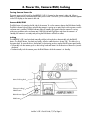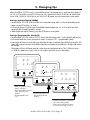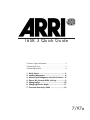
1
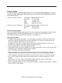
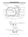
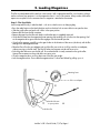
16SR 3 Quick Guide
Customer Support Information .........................................2
Camera Left & Front........................................................3
Camera Right & Back .....................................................4
1.
2.
3.
4.
5.
6.
7.
Quick Specs.................................................5
Loading Magazines .....................................6
Mounting the Magazine onto the Camera ....8
Power On, Camera RUN, Inching.................9
Changing Fps ............................................10
Changing Shutter Angle.............................11
Timecode Sensitivity Table .........................12
7/97a
Customer Support
If you have a question or problem, please contact one of our offices at the following addresses. In the case
of inquiries or when ordering parts, please refer to the camera model and serial number. Both are located
on the camera right side.
Arriflex Corporation, East Coast
617 Route 303, Blauvelt, NY 10913-1109
Voice phone:
914-353-1400
FAX:
914-425-1250
Email:
[email protected]
Website:
http://www.arri.com
Arriflex Corporation, West Coast
600 North Victory Blvd., Burbank, CA 91502-1639
Voice phone:
818-841-7070
FAX:
818-848-4028
About This Quick Guide
If you are viewing the Adobe Acrobat version of this Quick Guide, best viewing and printing results can be
achieved through the use of the Acrobat Reader version 3.0 or later. The Acrobat Reader can be
downloaded for free from the Adobe web site at http://www.adobe.com.
Safety Specifications
• In order to ensure optimal performance, it is essential that you acquaint yourself with this Quick Guide
and that you follow the operating instructions described herein. We strongly recommend that you also
acquaint yourself with the full 16SR 3 instruction manual.
• Assembly and initial operation should only be carried out after carefully reading the instructions and
familiarizing yourself with the equipment and the assembly procedures!
• Use only original ARRI accessories and replacement parts!
• Clean optical surfaces only with an optical brush or a clean optical cloth! In cases of solid dirt, moisten an
optical cloth with pure alcohol (or brand-name lens cleaner).
• Do not use solvents when cleaning the film path!
• When adjusting the mirror shutter, turn the camera off and remove the on-board battery or the power
cable! Accidentally running the camera while adjusting the mirror shutter can cause great damage.
• 16SR 2 magazines as they come from the factory cannot be used for Super 16 or Timecode recording.
• Do not use HS magazines (high speed) on the standard camera, nor standard magazines on the HS
camera!
• Never blow air into the lens opening! The indicator needle on the light meter can be damaged.
• Do not unscrew any screws which are sealed with locking paint!
• When using polarizing filters, use only circularly polarizing filters not linearly polarizing filters, or the light
meter will give incorrect readings.
Arriflex 16SR 3 Quick Guide, 7/97a, Page 2
Camera Left & Front
Magazine safety latch
Eyecup iris lever
Timecode sensitivity selector
Magazine release latch
Arriglow/meter switch
Magazine door lock
Door lock safety button
400 foot magazine,
take-up side
Film speed selector
On-board battery
Manual inching knob
Electronic inching/PHASE button
LCD display
Run indicator light
On-board
battery adapter
Locking slider
RUN button
Running light
SET button
SEL button
NORM - PS/CCU switch
Mirror shutter adjustment tool
MODE button
Friction adjustment
Image rotation release
Image rotation knob
PL mount
Accessory shoe
Arriflex 16SR 3 Quick Guide, 7/97a, Page 3
Camera Right & Back
400 foot magazine, feed side
Carrying handle
PL mount locking ring
PL/bayonet adapter
lens release button
Mounting rosette
Main power on/off switch
Pitch adjustment
RS receptacles (remote RUN & 24 V dc)
Mechanical film counter
(shows remaining unexposed film)
Heated eyecup cable receptacle
ACC receptacle
CCU receptacle
BAT receptacle (power input)
Arriflex 16SR 3 Quick Guide, 7/97a, Page 4
1. Quick Specs
Fps range:
16SR 3:
16SR 3 HS:
5.000 - 75.000 fps
5.000 - 150.00 fps
Mirror shutter:
45° to 180°, manually adjustable
Fixed settings at: 45°, 90°, 135°, 144°, 172.8°, 180°
Power:
BAT:
24 V dc, Fischer connector, pin #1 is negative, pin #2 is positive
Acceptable voltage range: 20 to 32 V dc
RS:
Pin #1 is GND, pin #2 is +24 V, pin #3 is /E-Run
Power output: 24 V dc; different versions of the 16SR 3 have
different ampere capabilities, check with your rental house
ACC:
Pin #4 is GND, pin #3 is +24 V dc
Power output: 24 V dc, 0.1 amps max.
CCU:
Pin #4 is GND, pin #3 is +24 V dc
Power output: 24 V dc, 0.4 amps max.
Fuses:
Main fuse: .................10 A Picofuse
Accessory fuse:..........2.5 A Picofuse
Both fuses are located on top of the electronics housing.
Fuses can only be accessed when the magazine is removed.
Note:
Movement:
One pull-down film transport claw and one registration pin
Flange focal distance: 16SR 3:
16SR 3 HS:
Temperature range:
Instead of the 2.5 A accessory fuse, newer electronics have a
self-resetting fuse that is not user accessible.
52.00 - 51.99 mm
51.97 - 51.96 mm
-4° Fahrenheit to +122° Fahrenheit (-20°Celsius to +50°Celsius)
Viewfinder Indicators: LED glows
Asynchronous camera operation
LED blinking Low battery (less than 20 volts). Exchange battery.
Display Indicators:
TC
TC blinking
bat
asy
end
fps blinking
Timecode is turned on
Timecode is turned on, but not recording properly
Low battery (less than 20 volts). Exchange battery.
Asynchronous camera operation
Camera ran out of film
ESU is not receiving a valid signal
More detailed specifications can be found in the "Technical Data" section of the 16SR 3 manual.
Arriflex 16SR 3 Quick Guide, 7/97a, Page 5
2. Loading Magazines
The film must be loaded with the emulsion side inwards. With single perforated film, use B winding. Always
make sure that a loop protector is on the magazine when it is not on the camera. Always make sure that the
aperture cover plate is on the camera when no magazine is attached to the camera.
Step 1: The Feed Side
Load unexposed film only in absolute dark - such as in a dark room or a changing bag.
• Press the safety button on the feed side door and turn the door lock counter clockwise to open the door.
• Slide the guide roller arm back until it clicks in the open position.
• Remove the film from the film container.
• Remove the tape from the film end. Make sure that the tape is completely removed.
• Guide the film head into the magazine throat opening and carefully push it further into the opening. Feel
on the magazine drive gear when the film engages with the internal sprocket.
• Once the film engages, carefully turn the gear further in the direction of the arrow (clockwise) until the film
emerges from the magazine throat.
• Place the film roll on the core adapter and push the film core as far as it will go onto the core adapter,
without pressing on the film itself. The film will otherwise become conical and cause noise.
• Push the guide roller arm onto the film roll. Ensure that the film is evenly centered on the guide roller.
Uneven film movement on the guide roller can cause noise.
• Close the magazine door, ensuring that none of the film gets caught.
• Lock the magazine door. Ensure that the magazine door is closed and locked by pulling up on it.
Retaining levers
Film core adapter
Guide roller arm
in open position
Guide roller
Arriflex 16SR 3 Quick Guide, 7/97a, Page 6
Step 2: The Take-up Side
Step 2 can be performed in daylight.
• Pull some film out of the magazine throat and place it along the under side of the magazine, until the first
perforation hole reaches the white index line.
• Hold the drive gear to keep the loop length stable. Push the film head gently into the take-up channel until
it engages with the take-up sprocket.
• As soon as the film engages noticeably with the take-up sprocket, turn the magazine drive gear
approximately five revolutions in the direction of the arrow.
• Place the magazine with the take-up side facing up and open the take-up side magazine door.
• Swing the guide roller arm back until it locks in the open position.
Collapsible core:
- Slide the film head into the opening of the collapsible core.
- Then lock the clamp lever. Ensure that the film is clamped straight and at the right
height. Otherwise, unwanted noise may result.
Film core:
- Place the film head in the slot of the plastic film core.
- With a fingernail, smooth out the film where it emerges to avoid uneven movement
of the guide roller arm.
• Turn drive gear five revolutions in the direction of the arrow until the film is sitting securely on the core.
• Carefully push the guide roller arm onto the film roll. Ensure that the film is evenly centered on the guide
roller. Uneven film movement on the guide roller can cause noise.
• If using timecode magazines, now is a good time to set the timecode sensitivity (TCS). Turn the selector
switch with your fingers to the desired value. See table at the end of this guide.
• Close and lock the magazine door and double check that the magazine door is properly locked.
• Hang the film loop between the four guide pins on the film pressure plate (two shaped as claws).
Magazine
drive gear
Guide pins
Magazine
drive gear
Take-up channel;
push film end in
here.
White index line
Arriflex 16SR 3 Quick Guide, 7/97a, Page 7
3. Mounting the Magazine onto the Camera
Mounting the Magazine
Note: You can use SR 1 and 2 magazines on the 16SR 3, and SR 3 magazines on the 16SR 1 and 2, but:
- Don't use high speed magazines on standard cameras or standard magazines on HS cameras.
- 16SR 1 and 2 magazines as they come from the factory cannot be used for Super 16 or Timecode.
• If appropriate, press the black button on the video carrying handle and swing it to the left side.
• If appropriate, swing back the on-board battery.
• Remove the loop protector from the magazine and the aperture cover plate from the camera.
• Center the film loop in reference to the pressure plate, and make sure the film is held in place by the four
guide pins.
• Flip the safety latch on the magazine to the back.
• Grasp the upper part of the magazine and hold it in a 30° slanted (two o'clock) position.
• Push the magazine towards the camera so that the guide pin on the magazine engages in the matching
groove on the camera.
• Carefully press the back part of the magazine down until it locks in place. Don't slam the magazine down!
Note: The red markings on the top of the magazine, behind the guide pin, should no longer be visible!
• Flip the safety latch to the front.
• If appropriate, swing the video carrying handle and/or the battery back in position.
• Push the PHASE button until you hear a click. This will ensure that the pulldown claw is properly engaged
in a film perforation. Running the camera without this step may lead to a film jam.
Setting the Counters
• Set the film sensitivity on the camera's exposure meter by turning the film speed selector until the correct
sensitivity number (shown in DIN and ASA) appears in the window.
• Reset the TOTAL film counter by pushing the SET button for approximately 3 seconds when viewing the
TOTAL counter on the LCD display.
• When using timecode, make sure that the proper timecode sensitivity value is set on the magazine. Once
the magazine is on the camera, the TCS value can still be changed with a Phillips head screwdriver.
Guide pin
Safety latch
Film speed selector
Arriflex 16SR 3 Quick Guide, 7/97a, Page 8
4. Power On, Camera RUN, Inching
Turning Camera Power On
The main power on/off switch for the ARRIFLEX 16SR 3 is located on the camera's right side. When a
battery is attached to the camera and the main power switch is turned on, you should see characters appear
on the LCD display on the camera's left side.
Camera RUN/STOP
The RUN button is located on the left side of the camera. To run the camera, depress the RUN button briefly.
The RUN indicator light will glow red while the camera is coming up to speed, and switch to green once the
set frame rate is reached. The RUN indicator light will steadily glow green when the camera is running
without any problems at the set frame rate. If the RUN indicator light glows red when the camera is in
Standby, the camera is not ready and pushing the RUN button will have no effect.
Inching
The ARRIFLEX 16SR 3 can be inched manually with the inching knob or electronically with the PHASE
button. The PHASE button, if pushed very briefly, will also rotate the mirror shutter 180°. This allows for a
fast gate check. To move the mirror shutter back in the viewing position, tap the PHASE button again briefly.
• To manually inch the camera, push on the inching knob and rotate it in the direction of the arrow (counterclockwise).
• To electronically inch the camera, press the PHASE button while the camera is in Standby.
Manual inching knob
Electronic inching/
PHASE button
RUN indicator light
RUN button
Arriflex 16SR 3 Quick Guide, 7/97a, Page 9
5. Changing Fps
When the NORM - PS/CCU switch is in the NORM position, the camera can run at the standard speeds of
24, 25, 29.97 and 30 fps. In the PS/CCU position, any speed from 5.000 to 75.000 fps can be achieved
on the 16SR 3 (5.000 to 150.00 fps on the 16SR 3 HS). All speeds set on the camera are crystal speeds.
Setting a Standard Speed (NORM)
• Set the NORM - PS/CCU switch to NORM. Ensure that the locking slider is in the unlocked (left) position.
• Make sure the LCD display is in mode 1.
• Push the SEL button to cycle through the available standard speeds (24, 25, 29.97 and 30 fps). Each
speed will flash for approximately 3 seconds.
• While the desired speed is flashing, push the SET button to set the speed.
Setting a Programmable Speed (PS)
• Set the NORM - PS/CCU switch to PS/CCU. Ensure that the locking slider is in the unlocked (left) position.
• Push the MODE button once to change from mode 1 to mode 2 ("PS" - programmable speed).
• Pressing the SEL button now will select one digit after the other. A selected digit will blink. Pressing the SET
button will increment the value of the blinking digit by one. Repeat this procedure for all digits that need to
be changed.
The display will show full frame speed plus three digits past the decimal point. The 1/1000 th of a fps
(1/100th for speeds over 99 fps) is shown in the upper right-hand corner of the display.
fps
P S
0
2 4.0 0
LOCK
fps
NORM
PS/CCU
MODE
SEL/▼
P S
0
2 4.0 0
SET/▲
LOCK
fps
NORM
PS/CCU
MODE SEL/▼
• Make sure that the locking
slider is unlocked.
• Move the NORM - PS/CCU
switch to the PS/CCU
position.
• Push the SEL button once.
• Push the MODE button
The first digit will start
once.
blinking.
P S
0
3 4.0 0
SET/▲
LOCK
NORM
PS/CCU
MODE
SEL/▼
SET/▲
• Push the SET button to change the
value of the blinking digit.
• Then push the SEL button again to
move to the next digit, and so on.
Arriflex 16SR 3 Quick Guide, 7/97a, Page 10
6. Changing Shutter Angle
Checking the Mirror Shutter Angle
• Make sure that the camera is in standby.
• Push the PHASE button and keep it held down. The camera will run at the inching speed (1 fps).
• After two seconds the top line of the LCD display will show the open angle of the mirror shutter.
Changing the Mirror Shutter Angle
Note: Before adjusting the mirror shutter, turn the camera off and remove the power cable or on-board
battery! Accidentally running the camera while adjusting the mirror shutter can cause great damage.
• Remove the lens or lens mount cavity cap.
• If appropriate, remove the PL/bayonet adapter.
• Push in and turn the manual inching knob until the adjustment screw is visible in the lens opening.
• Insert the mirror adjustment tool into the adjustment screw.
Note: The mirror shutter adjustment tool is a metric 2 mm hex driver with a protective rubber covering. It
can be found in the back of the camera housing. The mirror shutter can be damaged if a tool
without a protective rubber covering is used!
• Press down on the adjustment tool to engage the adjustment screw. Hold the mirror shutter in its position
with the manual inching knob. Turn the adjustment screw counterclockwise to reduce the open shutter
angle, clockwise to enlarge the open shutter angle.
• As you change the shutter angle, you will feel indents where the labeled shutter positions are. To set a
given angle, make sure that you stop at the appropriate indent position.
Note: When you close the shutter down, you have to compensate your exposure. Open up the lens
aperture one stop for a 90° and two stops for a 45° shutter angle.
Manual inching knob
Mirror adjustment tool
Adjustment screw
Arriflex 16SR 3 Quick Guide, 7/97a, Page 11
7. Timecode Sensitivity Table
Notes
This table is in effect as of July 1997.
Timecode recording is possible at the standard speeds of 23.976, 24, 25, 29.97 and 30 fps.
† = Emulsion no longer available from manufacturer.
* - Requires modified TC exposure module due to film's poor red sensitivity
16 mm Kodak Film Stocks
16 mm Fuji Film Stocks
Emulsion
Type
TCS
Emulsion
Type
TCS
7222
7231
7239
7240
7245
7248
7250
7251
7276
7277
7278
7279
7287
† 7292
7293
7296
7297
7298
7620
B/W Negative
B/W Negative
Color Reversal
Color Reversal
Color Negative
Color Negative
Color Reversal
Color Reversal
B/W Reversal
Color Negative
B/W Reversal
Color Reversal
Color Negative
Color Negative
Color Negative
Color Negative
Color Negative
Color Negative
Color Negative
8
9
5
6
6
6
5
4
*
5
*
4
6
4
5
5
6
4
6
† 8427
8428
8610
8620
8621
8630
8631
8650
8651
8660
8661
8670
8671
Color Reversal
Color Reversal
Color Negative
Color Negative
Color Negative
Color Negative
Color Negative
Color Negative
Color Negative
Color Negative
Color Negative
Color Negative
Color Negative
6
6
7
6
6
6
6
5
4
5
4
5
5
Arriflex 16SR 3 Quick Guide, 7/97a, Page 12