1
Service Handbook PUHY-80TMU-A, 100TMU-A
Service Handbook PUHY-80TMU-A, 100TMU-A
HEAD OFFICE MITSUBISHI DENKI BLDG. MARUNOUCHI TOKYO 100-0005 TELEX J24532 CABLE MELCO TOKYO
Issued in March 2004 MEE03K198
Printed in Japan
New publication effective March 2004.
Specifications subject to change without notice.
AIR CONDITIONERS CITY MULTI Series Y
Models
PUHY-80TMU-A, 100TMU-A
Service Handbook
Safety precautions
Before installation and electric work
•
s Before installing the unit, make sure you read all
the “Safety precautions”.
s The “Safety precautions” provide very important
points regarding safety. Make sure you follow
them.
s This equipment may have an adverse effect on
equipment on the same electrical supply system.
s Please report to or take consent by the supply authority before connection to the system.
•
•
•
•
Symbols used in the text
Warning:
Describes precautions that should be observed to prevent
danger of injury or death to the user.
•
Caution:
Describes precautions that should be observed to prevent
damage to the unit.
•
Symbols used in the illustrations
: Indicates an action that must be avoided.
: Indicates that important instructions must be followed.
•
: Indicates a part which must be grounded.
: Indicates that caution should be taken with rotating parts.
(This symbol is displayed on the main unit label.) <Color:
Yellow>
: Indicates that the main switch must be turned off before
servicing. (This symbol is displayed on the main unit label.)
<Color: Blue>
•
•
: Beware of electric shock (This symbol is displayed on the
main unit label.) <Color: Yellow>
: Beware of hot surface (This symbol is displayed on the main
unit label.) <Color: Yellow>
ELV : Please pay attention to electric shock because this
is not Safety Extra Low-Voltage (SELV) circuit.
And at servicing, please shut down the power supply
for both Indoor Unit and Outdoor Unit .
Warning:
•
•
Carefully read the labels affixed to the main unit.
Warning:
•
•
•
Ask the dealer or an authorized technician to install the air
conditioner.
- Improper installation by the user may result in water leakage,
electric shock, or fire.
Install the air unit at a place that can withstand its weight.
- Inadequate strength may cause the unit to fall down, resulting
in injuries.
Use the specified cables for wiring. Make the connections
securely so that the outside force of the cable is not applied to the terminals.
•
- Inadequate connection and fastening may generate heat and
cause a fire.
Prepare for typhoons and other strong winds and earthquakes and install the unit at the specified place.
- Improper installation may cause the unit to topple and result in
injury.
Always use an air cleaner, humidifier, electric heater, and
other accessories specified by Mitsubishi Electric.
- Ask an authorized technician to install the accessories. Improper installation by the user may result in water leakage,
electric shock, or fire.
Never repair the unit. If the air conditioner must be repaired, consult the dealer.
- If the unit is repaired improperly, water leakage, electric
shock, or fire may result.
Do not touch the heat exchanger fins.
- Improper handling may result in injury.
If refrigerant gas leaks during installation work, ventilate
the room.
- If the refrigerant gas comes into contact with a flame, poisonous gases will be released.
Install the air conditioner according to this Installation
Manual.
- If the unit is installed improperly, water leakage, electric
shock, or fire may result.
Have all electric work done by a licensed electrician according to “Electric Facility Engineering Standard” and
“Interior Wire Regulations”and the instructions given in
this manual and always use a special circuit.
- If the power source capacity is inadequate or electric work is
performed improperly, electric shock and fire may result.
Securely install the cover of control box and the panel.
- If the cover and panel are not installed properly, dust or water
may enter the outdoor unit and fire or electric shock may result.
When installing and moving the air conditioner to another
site, do not charge it with a refrigerant different from the
refrigerant (R22) specified on the unit.
- If a different refrigerant or air is mixed with the original refrigerant, the refrigerant cycle may malfunction and the unit may be
damaged.
If the air conditioner is installed in a small room, measures
must be taken to prevent the refrigerant concentration from
exceeding the safety limit even if the refrigerant should
leak.
- Consult the dealer regarding the appropriate measures to prevent the safety limit from being exceeded. Should the refrigerant leak and cause the safety limit to be exceeded, hazards
due to lack of oxygen in the room could result.
When moving and reinstalling the air conditioner, consult
the dealer or an authorized technician.
- If the air conditioner is installed improperly, water leakage,
electric shock, or fire may result.
After completing installation work, make sure that refrigerant gas is not leaking.
- If the refrigerant gas leaks and is exposed to a fan heater,
stove, oven, or other heat source, it may generate noxious
gases.
Do not reconstruct or change the settings of the protection
devices.
- If the pressure switch, thermal switch, or other protection device is shorted and operated forcibly, or parts other than those
specified by Mitsubishi Electric are used, fire or explosion may
result.
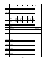
Contents
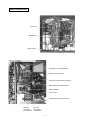
1 COMPONENT OF EQUIPMENT ............................................... 1
[1] Appearance of Components ............................................ 1
[2] Refirigerant
iger
Circuit Diagram and Thermal Sensor........... 6
[3] PUHY-80, 100TMU-A ELECTRICAL WIRING
DIAGRAM ....................................................................... 7
[4] Standard operation data .................................................. 9
[5] Function of dip SW and rotary SW ................................ 11
2 TEST RUN ............................................................................... 15
[1] Before Test Run ............................................................ 15
[2] Test Run Method ........................................................... 19
3 GROUPING REGISTRATION OF INDOOR UNITS WITH
M-NET REMOTE CONTROLLER ........................................... 20
4 CONTROL ............................................................................... 26
[1] Control of Outdoor Unit ................................................. 26
[2] Operation Flow Chart .................................................... 31
[3] List of Major Component Functions ............................... 36
[4] Resistance of Temperature Sensor ............................... 38
5 REFRIGERANT AMOUNT ADJUSTMENT .............................. 39
[1] Refrigerant Amount and Operating Characteristics ....... 39
[2] Adjustment and Judgement of Refrigerant Amount ....... 39
6 TROUBLESHOOTING ............................................................. 44
[1] Principal Parts ................................................................ 44
[2] Self-diagnosis and Countermeasures Depending on the
Check Code Displayed .................................................. 62
[3] LED Monitor Display ...................................................... 83
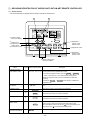
Propeller fan
Fan motor
-1-
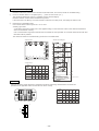
Rear Controller Box
INV board
MAIN board
Choke coil(L2)
Interrigent Power Module(IPM)
Magnetic contactor(52C)
Capacitor (C1)(Smoothing capacitor)
Gate Amplifier board(G/A board)
Diode stack(DS)
Power board
Terminal block(TB7)Transmission
Terminal
block (TB1)
Power source
Terminal
block (TB3)
Transmission
-2-
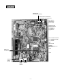
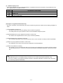
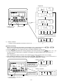
MAIN board
CNS1 M-NET
Transmission (DC30V)
CNS2 M-NET Transmission
(Centralized control) (DC30V)
CN40 M-NET
Transmission
Power supply
CNVCC3 Power
source for contorl
1-2 DC30 V
1-3 DC30 V
4-6 DC12 V
5-6 DC5 V
CN51 Indication distance
3-4 Compressor ON/
Off
3-4 trouble
LD1
Service LED
CNRS53
Serial transmission to
INV board
CN3D
SW1,2,3,4
Dip Switch
CN3S
CNFAN1
control
for MF1
CN20
power
source
CNAC3
-3-
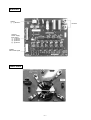
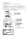
INV board
CNDC2
1-3 DC310 V
CN15V2
Power supply IPM control
1-2 DC15 V
5-6 DC15 V
9-0 DC15 V
C-D DC15 V
CNVCC4
CNL2
Choke coil
CNVCC2
power
supply
CNDR2
IPM control
signal
CNCT
CNTH
CNAC2
CN52C
Power source
Control for
1 L2
52C
5N
CNFAN
Control for
MF1
CNRS2
Serial transmission
to MAIN board
-4-
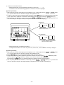
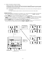
SW1
G/A board
CNDC1
1 - 3 DC310V
DC310V
CN15V1
Power Supply
IPM control
1 - 2 DC15V
5 - 6 DC15V
9 - 0 DC15V
C - D DC15V
CNDR1
IPM control signal
Power board
-5-
TH6
HEXB
TH5
HEXF
-6-
TH8
SCC
63H
CV1
ST6
Comp
TH1
O/S
LEV1
SV2
SV1
CP1
63HS
CJ1
ST7
TH7
MA
SLEV
Accumulator
SA
High pressure safety valve
CJ2
ST2
CP2
TH2
ST1
BV2
Indoor
Unit
BV1
[2] Refirigerant Circuit Diagram and Thermal Sensor
1 PUHY-80TMU-A, 100TMU-A
-7-
63H
MF
SV
2
21
S4
SV1
CH1
L3
L2
DSA
CN20
(7P)
White
Red
Black
3 5
F2
6.3A
X05
X04
X02
X01
1
SW1
SWU2 SWU1
SW2
10
TH1
CN01
(2P)
1 2
CNH
(3P)
1 2 3
Unit address setting switch
SW3
10
TH5 TH8 TH7 TH2
SW4
10
TH6
10
52C
Control circuit board
(MAIN-BOARD)
Shield
R1
OFF ON OFF ON OFF ON OFF ON
1
1
1
1
LD1
B
1 2 3
CNS2
(3P)
CN02
(8P)
1 2 3 4 5 6 7 8
CN41
(4P)
1 2
CNS1
(2P)
Red
CN03
(3P)
1 2 3
ZNR1~4
CN40
(4P)
1 2 3 4
FN1
TB7
A B
A
Black
Red
TB3
1 2 3 4
-
+
DS(Diode stack)
F1
6.3A
7
G L3 L2 L1
Green
3 CN38
2 (3P)
1 Green Detection
Circuit
5
4 CNFAN1
3 (5P)
2
1 Red
6 CN34
5 (6P)
4 Red
3
2
1
6 CN33
5 (6P)
4
3
2
1
3 CN32
2 (3P)
1
Ground
Connect to
indoor and
remote
controller GR
Power source
3~208~230V
60Hz
TB1
L1
3 2 1
3
2
1
12V
3
2
1
LEV1
1
2
3
4
5
CNLV2
(5P)
Red
CN3S
(3P)
Red
CN3D
(3P)
Snow sensor
Compressor ON/OFF
Night mode
White
Black
L2
CNDR1
(9P)
CN15V1
(14P)
CN15V2
(14P)
MF
1
SW3-10 are OFF for Model 80.
and ON for Model 100.
R2
Red
Red
CN30V
CNFAN
(2P)
(3P)
1 2
1 2 3
X01
Power circuit board
(INV-BOARD)
CNDR2
(9P)
123456789 1234567891011121314
123456789 1234567891011121314
CNL2
(2P)
1 2
F01
2A
Green
CNTH
(2P)
1 2
5 Trouble
4 Compressor ON/OFF
3
THHS
2 CN51
1 (5P)
SLEV
1
2
3
4
5
1 CNAC2
2 (5P)
3
4
5
1 CNVCC4
2 (2P)
CNVCC5 1
2
(2P)
CNAC3 1
2
(5P)
3
4
5
1
2 CNVCC2
3 (6P)
4
5
6
1
CNVCC3 2
3
(6P)
4
5
6
G
L3
L1
123
CNCT CNDC2
1 (4P) (3P)
2 CN52C Yellow
3 (3P)
1
2 CNRS2
3 (7P)
4
5
6
7
G
L3
L1
52
C
1
CNRS3 2
3
(7P)
4
5
6
7
DCCT
Red
MC
U
W
V
U
V
W
Gate amp board
(G/A-BOARD)
CNE 1
F01
(2P)
3.15A
2
IPM
Yellow
CNDC1 1 2 3
(3P)
N
P
1 2 3 4
Black
Red
1 2 3 4
+
DCL
C
1
FN4
FN6
CNLV1
(5P)
Blue
FN2
FN3
Noise filter board
(POWER-BOARD)
63HS
Black
White
Red
Ground
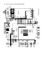
[3]
PUHY-80, 100TMU-A ELECTRICAL WIRING DIAGRAM
-8-
Name
Crankcase heater (Compressor)
CH1
DC reactor
(Power factor improvement)
Current Sensor
DCL
DCCT
TH1
TH2
TH5
Capacitor Smoothing
Magnetic contactor
(Inverter main circuit)
Motor Compressor
ZNR1~4
C1
52C
MC
LEV1
L2
pipe temp.detect
SLE V
63HS
THHS
TH8
TH7
saturation
evapo.temp.detect
Thermistor discharge pipe temp.detect
High pressure switch
Solenoid valve
(Discharge-suction bypass)
Symbol
TH6
1 2 3 4 5 6 7 8 9 10
(at factory shipment)
ON : 1
OFF : 0
Check display
(Blinking)
Relay output
display
(Lighting)
Display
Crankcase
heater
During
compressor
run
21S4
FLAG3
SV1
FLAG4
SV2
FLAG5
FLAG6
FLAG7
Always
lighting
FLAG8
Choke coil(Transmission)
Electronic expansion valve
(Sub-cool coil bypass)
Electronic expansion valve
(Oil return)
High pressure sensor
0000~9999
Display the address and error codes by turns
FLAG2
Symbol
GR
TB7
TB3
TB1
SWU1~2
S W 2 ~4
SW1
LD1
FLAG8 always lights at
microcomputer power ON
bypass outlet temp.
detect at Sub-cool coil
liquid outlet temp.
detect at Sub-cool coil
Rediator panel temp.detect
Display at LED lighting (blinking) Remarks SW1 operation
FLAG1
Name
Thermistor OA temp.detect
<Operation of self-diagnosis switch (SW1) and LED display>
63H
Varistor
R2
SV1,SV2
Resistor rush current protect
Resistor power regulation
R1
4-way valve
Surge absorber
DSA
21S4
Motor Fan Radiator panel
MF1
Intelligent Power Module
Motor Fan Heat exchanger
IPM
Symbol
MF
Name
Diode stack
Symbol
DS
Nam e
LD1
<LED display>
Ground terminal
Terminal block transmisson
centralized control
Terminal block transmisson
Terminal block power source
Switch unit address set
Switch function selection
FLAG8
FLAG7
FLAG6
FLAG5
FLAG4
FLAG3
FLAG2
FLAG1
Switch display selection self-diagnosis
Luminous diode
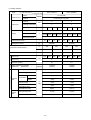
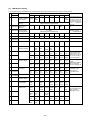
[4]
Standard operation data
1 Cooling operation
Outdoor units
Items
PUHY-80TMU-A
26.7°C(80°F)/19.4°C(67°F)
Indoor
Ambient temp.
PUHY-100TMU-A
DB/WB
35°C(95°F)
Outdoor
Quantity
4
4
4
4
Set
Condition
Indoor unit
Quantity in operation
–
Model
24
24
Branch pipe
m
(Ft)
16
24
Hi
Hi
kg(oz)
10
5(16.4)
25(82)
–
Refrigerant volume
48
5(16.4) 5(16.4) 5(16.4) 5(16.4) 5(16.4) 5(16.4)
Total piping length
Indoor unit fan notch
10
5(16.4)
Main pipe
Piping
20
5(16.4) 5(16.4)
25(82)
Hi
Hi
Hi
Hi
10.2(360)
Hi
Hi
12.5(441)
V
208
230
208
230
V/Hz
134/76
134/76
171/98
171/98
A
27.4
24.8
Compressor volts/Frequency
Pressure LEV opening
Outdoor unit
Indoor unit
440
SC (LEV1)
Pulse
Oil return (SLEV)
High pressure/Low pressure
(after O/S)
(before MA)
440
380
300
35.2
450
31.8
320
440
75
81
111
157
2.00/0.50
(290/72)
1.99/0.46
(288/67)
Discharge (TH1)
85(185)
95(203)
Heat exchanger outlet (TH5)
40(104)
42(108)
Inlet
7(45)
5(41)
Outlet
9(48)
7(45)
7(45)
10(50)
6(43)
4(39)
60(140)
60(140)
SCC outlet (TH7)
27(81)
27(81)
Bypass outlet (TH8)
8(46)
6(43)
LEV inlet
26(79)
26(79)
Heat exchanger outlet
10(50)
10(50)
MPa(psi)
Sectional temperature
Accumulator
Outdoor
unit
Suction (Comp)
low pressure saturation
temperature (TH2)
°C
(°F)
Shell bottom (Comp)
Indoor
unit
-9-
300
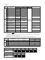
2 Heating operation
Outdoor units
Items
PUHY-200TM-A
21.1°C(70°F)
Indoor
Ambient temp.
PUHY-250TM-A
DB/WB
8.3°C(47°F)/6.1°C(43°F)
Outdoor
Quantity
4
4
4
4
Set
Quantity in operation
Condition
Indoor unit
–
Model
24
24
Branch pipe
m
–
Refrigerant volume
kg
Pressure LEV opening
Hi
Hi
Hi
Hi
Hi
Hi
Hi
12.5(441)
208
230
V/Hz
149/85
149/85
174/100
174/100
A
27.5
24.9
35.6
32.2
510
450
300
350
380
510
0
0
87
111
1.72/0.36
(249/52)
1.72/0.36
(249/52)
80
85(185)
6(46)
8(46)
Inlet
–1(30)
–2(28)
Outlet
–1(30)
–2(28)
–1(30)
–2(28)
low pressure saturation
temperature (TH2)
–2(28)
–2(28)
Shell bottom (Comp)
35(95)
44(111)
Heat exchanger inlet
71(160)
71(160)
LEV inlet
33(91)
33(91)
Oil return (SLEV)
MPa(psi)
Heat exchanger inlet (TH5)
Accumulator
Suction (Comp)
Hi
230
Discharge (TH1)
Sectional temperature
25(82)
208
Pulse
High pressure/Low pressure
(after O/S)
(before MA)
10
5(16.4)
10.2(360)
510
SC (LEV1)
Indoor
unit
24
V
Indoor unit
Outdoor
unit
16
25(82)
Indoor unit fan notch
Outdoor unit
48
5(16.4) 5(16.4) 5(16.4) 5(16.4) 5(16.4) 5(16.4) 5(16.4) 5(16.4)
Total piping length
Compressor volts/Frequency
10
5(16.4)
Main pipe
Piping
20
°C
(°F)
- 10 -
300
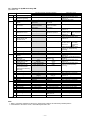
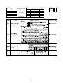
[5]
Function of dip SW and rotary SW
(1) Outdoor unit
Switch
SWU
SW1
SW2
Function
1~2
1~8
Unit Address Setting
For self diagnosis/
operation monitoring
9~10
–
1
Centralized Control
Switch
2
Deletion of connection
information.
SW3
–
Centralized control not
connected.
Storing of refrigeration
system connection
information.
–
–
Centralized control
connected.
Deletion of refrigeration
system connection
information.
Deletion
3
Deletion of error history.
4
Adjustment of
Refrigerant Volume
Ordinary control
Refrigerant volume
adjustment operation.
5
6
–
Errors valid.
–
Disregard errors.
7
–
Disregard ambient air
sensor errors, fluid
overflow errors.
Forced defrosting
Ordinary control
Start forced defrosting.
8
Defrost prohibited timer
50 min.
9
10
1
–
–
SW3-2 Function Valid/
Invalid
Indoor Unit Test
Operation
Defrosting start
temperature of TH5.
Defrosting end
temperature of TH5.
Opening angle of IC
except when heater
thermostat is ON during
defrosting.
–
–
Target Pd (High pressure)
–
–
SW3-2 Function Invalid
–
–
SW3-2 Function Valid
Stop all indoor units.
All indoor units test
operation ON.
0 °C
(32°F)
15 °C
(59°F)
2000
2
3
4
5
6
7
8
9
10
1
2
3
4
5
6
7
8
9
SW4
Function According to Switch Operation
When Off
When On
Set on 00 or 51~100 with the dial switch. (✻2)
LED Monitering Display
10
–
–
Models
–
–
–
–
LED Display
–
–
–
Fan characteristics
(
)
–
90 min.
-2 °C
(28.4°F)
8HP: 12°C(53.6°F)
10HP: 8°C(46.4°F)
(no operation)
–
–
18kg/cm2G
(256psi)
–
–
Model 80
–
–
–
–
"°F" "psig" Display
–
–
–
Standard
–
–
20kg/cm2G
(284psi)
–
–
Model 100
–
–
–
–
"°C" "kgf/cmG "Display
–
–
–
High external
static pressure
–
–
Switch Set Timing
When Off
When On
Before power is turned on.
During normal operation when
power is on.
Should be set on OFF.
Before power is turned on.
Before power is turned on.
During normal operation when
power is on.
During normal
Invalid 2 hours
operation when
after compressor
power is on.
starts.
–
During normal operation when
power is on.
10 minutes or
more after
compressor
starts.
During normal operation when
power is on. (Except during
defrosting)
–
–
During normal operation when
power is on.
When SW3-1 is ON after power is
turned on.
During normal operation when
power is on.
During normal operation when
power is on. (Except during
defrosting)
During normal
operation when
power is on.
–
When switching on the power.
During normal operation when
power is on.
–
–
When switching on the power.
–
–
–
–
When switching on the power
–
–
–
When switching on the power
–
✻1
Note:
1. SWU1~2=00 when shipped from the factory. Other factory settings are indicated by shaded portions.
2. If the address is set from 01 to 50, it automatically becomes 100.
- 11 -
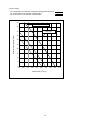
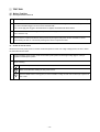
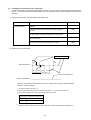
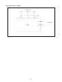
2. SW4-9 setting
Fan characteristics curve:DIPSW4-7OFF[FactorySetting],208V•230V/60Hz
Fan characteristics curve:DIPSW4-7ON,208V/60Hz
Fan characteristics curve:DIPSW4-7ON,230V/60Hz
50
Continuous operation range
45
Standard Airflow rate
200(m3/min)
External static pressure (Pa)
40
35
30
25
20
15
10
5
0
150
160
170
180
190
200
210
Airflow rate (m3/min)
- 12 -
220
230
240
(2) Indoor unit
DIP SW1, 3
Switch
SW1
Switch set timing
OFF
ON
Indoor unit inlet
Built in remote controller
None
Provided
1
Room temp. sensor position
2
Clogged filter detect.
3
Filter duration
4
OA intake
5
Remote display select.
Fan output display Thermo. ON signal display
6
Humidifier control
At stationary heating
Always at heat.
7
Heating thermo. OFF airflow
Very low speed
Low speed
8
Heating thermo. OFF airflow
SW1-7 setting
Set airflow
9
Power failure automatic
return
Ineffective
Effective
–
–
Heat pump
Cool.only
None
Provided
10
1
SW3
Operation by SW
OFF
ON
SW name
–
Model selection
Cooling capacity saving
for PKFY-NAMU,
effective/ineffective
100h
2500h
Ineffective
Effective
Always ineffective for PKFY-NAMU
2
Louver
3
Vane
None
Provided
4
Vane swing function
None
Provided
5
Vane horizontal angle
1st setting
2nd setting
6
Vane angle set for cooling
Down blow B, C
Horizontal
–
–
Effective
Ineffective
7
8
–
Heating 4deg (7.2 deg) up
Note : °C scale (°F scale)
9
–
–
–
10
–
–
–
Remarks
At unit stopping
(at remote
controller OFF)
Not provided for PKFY-NAMU
Provided for PLFY-NGMU (ON) setting
Always down blow B,C for
PKFY-NAMU
Note 1: The shaded part
indicates the setting at factory shipment. (For the SW not being shaded, refer to the
table below.)
2: The DipSW setting is only effective during unit stopping (remote controller OFF) for SW1, 2, 3 and 4 commonly
and the power source is not required to reset.)
3: When both SW1-7 and SW1-8 are being set to ON, the fan stops at the heating thermostat of OFF.
Model
PKFY
PLFY-NAMU-A
PDFY-NMU-A
3
ON
ON
OFF
6
ON
ON
OFF
7
OFF
OFF
OFF
3
ON
OFF
4
ON
OFF
6
OFF
OFF
OFF
8
OFF
OFF
OFF
NAMU-A
Switch
SW1
SW3
NGMU-A
ON
OFF
ON
Setting of DIP SW2
Model
08
10
12
16
20
24
Capacity (model name) code
4
5
6
8
10
13
SW2 setting
ON
OFF
ON
OFF
ON
OFF
ON
OFF
Model
32
40
48
Capacity (model name) code
16
20
25
SW2 setting
ON
OFF
ON
OFF
ON
OFF
- 13 -
ON
OFF
ON
OFF
Setting of DIP SW4
Model
Setting of DIP SW5
Circuit board used
SW4
1
2
3
4
PDFY-10 ~ 32
ON
OFF
ON
OFF
PLFY-12 ~ 24
OFF
OFF
OFF
ON
PLFY-32 ~ 48
Phase control
ON
OFF
OFF
ON
PKFY-P-8
OFF
OFF
ON
ON
PKFY-P-12
–
–
–
–
OFF
OFF
ON
–
PDFY-40, 48
Relay selection
✻
✻
✻
- 14 -
2 TEST RUN
[1] Before Test Run
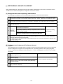
(1) Check points before test run
1
Neither refrigerant leak nor loose power source/ transmission lines should be found, if found correct immediately.
2
Confirm that the resistance between the power source terminal block and the ground exceeds 2MΩ by measuring it with a DC500V megger. Do not run if it is lower than 2MΩ.
Note : Never apply the megger to the MAIN board. If applied, the MAIN board will be broken.
3
Confirm that the Ball valve at both gas and liquid sides are fully opened.
Note : Close the cap.
4
Be sure that the crankcase heater has been powered by turning the main power source on at least 12 hours
before starting the test run. The shorter powering time causes compressor trouble.
(2) Caution at inverter check
Because the inverter power portion in outdoor unit electrical part box have a lot of high voltage portion, be sure to follow
the instructions shown below.
1
During energizing power source, never touch inverter power portion because high voltage (approx. 320V) is
applied to inverter power portion.
When checking,
1
Shut off main power source, and check it with tester, etc.
2
Allow 10 minutes after shutting off main power source.
3
Open the MAIN board mounting panel, and check whether voltage of both ends of electrolytic capacitor is
20V or less.
2
- 15 -
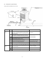
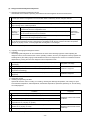
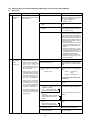
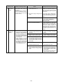
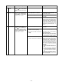
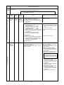
(3) Check points for test run when mounting options
Built-in optional parts
Mounting of drain
water pump
mechanism
Check point
Content of test run
1
Release connector of pump circuit,
check error detection by pouring
water into drain pan water inlet.
Result
Local remote controller displays code
No. “2503”, and the mechanism stops.
No overflow from drain pan.
Mounting of permeable film humidifier
Drain water comes out by operation of
drain pump.
2
After that, connect connector of
circuit.
3
Check pump operations and drainSound of pump operations is heard, and
age status in cooling (test run) mode. drain water comes out.
Check humidifier operations and water
supply status in heating (test run) mode.
No water leak from connecting portions
of each water piping.
Water is supplied to water supply tank,
and float switch is operating.
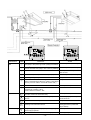
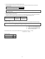
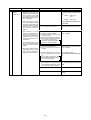
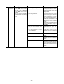
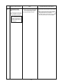
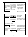
(4) Attention for mounting drain water pump mechanism
Work
Disassembling and
assembling of drain
water pump
mechanism
Mounting of float
switch
Electric wiring
Check point
Content of test run
1
Lead wire from control box not
damaged.
2
Rubber cap properly inserted in to
drain water outlet of drain pan?
3
Insulation pipe of gas and liquid
pipes dealt with as shown on next
page?
4
Drain pan and piping cover mounted
without gap?
5
Drain pan hooked on cut projection
of the mechanism?
Float switch installed without contacting the
drain pan?
Insulation pipe
No gap
1
Float switch moves smoothly.
2
Float switch is mounted on
mounting board straight without
deformation.
3
Float switch does not contact the
copper pipe.
1
No mistakes in wiring?
Wiring procedure is exactly followed.
2
Connectors connected securely and
tightly?
Connector portion is tightly hooked.
3
No tension on lead wire when sliding
control box?
- 16 -
Result
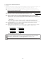
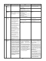
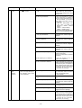
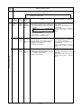
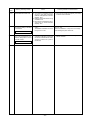
(5)
Check points for system structure
Check points from installation work to test run.
Classification
Installation and
piping
Power source
wiring
Portion
Check item
Trouble
1
Instruction for selecting combination of outdoor unit,
and indoor unit followed? (Maximum number of indoor
Not operate.
units which can be connected, connecting model name,
and total capacity.)
2
Follow limitation of refrigerant piping length? For example,
70m (229ft) or less (total length : 220m (721ft)) at the farthest.
Not cool (at cooling).
3
Connecting piping size of branch piping correct?
4
Refrigerant piping diameter correct?
5
Refrigerant leak generated at connection?
Not cool, not heat, error stop.
6
Insulation work for piping properly done?
Condensation drip in piping.
7
Specified amount of refrigerant replenished?
Not cool, not heat, error stop.
8
Pitch and insulation work for drain piping properly done? Water leak, condensation drip in drain piping.
Not heat (at heating).
1
Specified switch capacity and wiring diameter of main
power source used?
Error stop, not operate.
2
Proper grounding work done on outdoor unit?
Electric shock.
3
The phases of the L line (L1, L2, L3) correct?
Error stop, not operate.
- 17 -
DRY COOL
AUTO FAN
HEAT
CENTRALLY CONTROLLED
DAILY TIMER AUTO AUTO
CLOCK ON OFF
CHECK SET TEMP. REMAINDER
2
3
MODE
EROR CODE
TIMER
CLOCK ON OFF
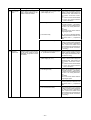
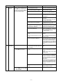
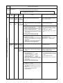
Classification
Portion
Transmission
line
1
System set
Before starting
TEST RUN
ON/OFF
FAN SPEED
CENTRALLY CONTROLLED
DAILY TIMER AUTO AUTO
CLOCK ON OFF
CHECK SET TEMP. REMAINDER
EROR CODE
MODE
TIMER
CLOCK ON OFF
VENTILATION CHECK TEST
TIMER SET
ON/OFF
FAN SPEED
LOUVER
PAR-F27MEA-US
Check item
FILTER
TEST RUN
NOT AVAILABLE
SET TEMP.
AIR DIRECTION FILTER
SENSOR
INSIDE
FAN
SPEED
VENTILATION
STAND BY
DEFROST
NOT AVAILABLE
LOUVER
PAR-F27MEA-US
AUTO FAN
FILTER
HEAT
SET TEMP.
1
DRY COOL
SENSOR
INSIDE
FAN
SPEED
VENTILATION
STAND BY
DEFROST
AIR DIRECTION FILTER
VENTILATION CHECK TEST
TIMER SET
Trouble
Erroneous operation, error stop.
Limitation of transmission line length followed? For example,
200m (656ft) or less (total length : 500m (1640ft)) at the farthest.
2
Erroneous operation, error stop.
1.25mm2 (AWG16) or more transmission line used?
(Remote controller 10m (32ft) or less 1.25mm2 (AWG16))
3
2-core cable used for transmission line?
4
Transmission line apart from power source line by 5cm (2in) or more? Erroneous operation, error stop.
5
One refrigerant system per transmission line?
6
The short circuit connector is changed form CN41 to
Not operate.
CN40 on the MAIN board when the system is centralized
control? (Just one outdoor unit. Not all outdoor units.)
7
• No connection trouble in transmission line?
Error stop or not operate.
8
Connection of wrong remote controller line terminals?
• MA Remote controller : TB15
• M-NET Remote controller : TB5
Never finish the initial mode.
1
Address setting properly done? (M-NET Remote
controller, indoor unit and outdoor unit.)
Error stop or not operate.
2
Setting of address No. done when shutting off power
source?
Can not be properly set with power
source turned on.
3
Address numbers not duplicated?
Not operate.
4
Turned on SW3-8 on indoor unit circuit board when
mounting room thermistor sensor?
Set temperature not obtained at
heating operations (Thermostat
stop is difficult)
1
Refrigerant piping ball valve (Liquid pressure pipe, gas
pressure pipe) opened?
Error stop.
2
Turn on power source 12 hours before starting operations? Error stop, compressor trouble.
- 18 -
Error stop in case multiple-core
cable is used.
Not operate.
[2] Test Run Method
Operation procedure
1
Turn on universal power supply at least 12 hours before starting → Displaying “HO” on display panel for about two
minutes
2
Press TEST button twice → Displaying “TEST RUN’’ on display panel
3
Press MODE button → Make sure that air is blowing out
4
Press MODE button to change from cooling to heating operation, and vice versa
air is blowing out
5
Press FAN SPEED adjust button → Make sure that air blow is changed
6
Press AIR DIRECTION or LOUVER button to change direction of air blowing make sure that horizontal or
downward blow is adjustable.
7
Make sure that indoor unit fans operate normally
8
Make sure that interlocking devices such as ventilator operate normally if any
9
Press ON/OFF
Make sure that warm or cold
button to cancel test run → Stop operation
Note 1:
2:
3:
4:
If check code is displayed on remote controller or remote controller does not operate normally.
Test run automatically stops operating after two hours by activation of timer set to two hours.
During test run, test run remaining time is displayed on time display section.
During test run, temperature of liquid pipe in indoor unit is displayed on remote controller room temperature
display section.
5: When pressing FAN SPEED adjust button, depending on the model, “NOT AVAILABLE” may be displayed on
remote controller. However, it is not a malfunction.
6: When pressing AIR DIRECTION or LOUVER button, depending on the model, “NOT AVAILABLE” may be
displayed on remote controller. However, it is not a malfunction.
- 19 -
3 GROUPING REGISTRATION OF INDOOR UNITS WITH M-NET REMOTE CONTROLLER
(1) Switch function
• The switch operation to register with the remote controller is shown below:
i
ii
CENTRALLY CONTROLLED
DAILY TIMER AUTO AUTO
DRY COOL
AUTO FAN
HEAT
CLOCK ON
CHECK SET TEMP. REMAINDER
FILTER
VENTILATION
STAND BY
DEFROST
C Switch to assign
indoor unit address
SENSOR
INSIDE
FAN
SPEED
OFF
EROR CODE
NOT AVAILABLE
SET TEMP.
F Delete switch
G Registered mode
selector switch
E Confirmation switch
MODE
TIMER
TEST RUN
ON/OFF
CLOCK ON OFF
FAN SPEED
LOUVER
AIR DIRECTION FILTER
A Registration/
ordinary mode
selector switch
VENTILATION CHECK TEST
D Registration switch
TIMER SET
PAR-F27MEA-US
B Registration/
ordinary mode
selector switch
H Switch to assign interlocked unit address
Name
Symbol
of switch
Name of actual switch
Registration/ordinary
mode selection switch
A+ B
FILTER + LOUVER
Description
This switch selects the ordinary mode or registered mode (ordinary
mode represents that to operate indoor units).
✻ To select the registered mode, press the FILTER + LOUVER
button continuously for over 2 seconds under stopping state.
[Note] The registered mode can not be obtained for a while after
powering.
Pressing the FILTER + LOUVER button displays “CENTRALLY
CONTROLLED”.
Switch to assign indoor
unit address
C
Registration switch
D
Confirmation switch
E
Delete switch
F
Registered mode
selector switch
G
of TEMP
TEST RUN
H
This button is used for group/interlocked registration.
TIMER
This button is used to retrieve/identify the content of group and
interlocked (connection information) registered.
CLOCK→
ON→OFF
This button is used to retrieve/identify the content of group and
interlocked (connection information) registered.
MODE
Switch to assign
interlocked unit address
This button assigns the unit address for “INDOOR UNIT ADDRESS
NO.”
This button selects the case to register indoor units as group (group
setting mode) or that as interlocked (interlocked setting mode).
✻The unit address is shown at one spot
for the group setting mode
while at two spots
for the interlocked setting mode.
of TIMER SET This button assigns the unit address of “OA UNIT ADDRESS NO.”
- 20 -
(2) Attribute display of unit
• At the group registration and the confirmation/deletion of registration/connection information, the type (attribute) of the
unit is displayed with two English characters.
Display
Type (Attribute) of unit/controller
Indoor unit connectable to remote controller
Outdoor unit
Local remote controller
System controller (MJ)
[Description of registration/deletion/retrieval]
• The items of operation to be performed by the remote controller are given below. Please see the relating paragraph for
detail.
1 Group registration of indoor unit
• The group of the indoor units and operating remote controller is registered.
• It is usually used for the group operation of indoor units with different refrigerant system.
2 Retrieval/identification of group registration information of indoor units
• The address of the registered indoor units in group is retrieved (identified).
3 Retrieval/identification of registration information
• The connection information of any unit (indoor/outdoor units, remote controller or the like) is retrieved (identified).
4 Deletion of group registration information of indoor units
• The registration of the indoor units under group registration is released (deleted).
5 Deletion of the address not existing
• This operation is to be conducted when “6607” error (No ACK error) is displayed on the remote controller caused by
the miss setting at test run, or due to the old memory remained at the alteration/modification of the group composition.
Caution:
When MELANS (G-50 for example) is being connected, do not conduct the group/pair registration using
the remote controller. The group/pair registration should be conducted by MELANS. (For detail, refer to the instruction exclusively prepared for MELANS.)
- 21 -
(3) Group registration of indoor unit
1) Registration method
• Group registration of indoor unit ........................................................................ 1
The indoor unit to be controlled by a remote controller is registered on the remote controller.
[Registration procedure]
1 With the remote controller under stopping or at the display of “HO”, continuously press the FILTER + LOUVER button
( A + B ) at the same time for 2 seconds to change to the registration mode. (See the figure below.)
2 Assign the indoor unit address to “INDOOR UNIT ADDRESS NO.” by operating the
(Room temperature
adjustment) ( C).
Then press the TEST RUN button ( D) to register. In the figure below, the “INDOOR UNIT ADDRESS NO.” is being set
to 001.
3 After completing the registration, press the FILTER + LOUVER button ( A + B ) at the same time for 2 seconds to
change to the original ordinary mode (with the remote controller under stopping).
Ordinary mode
• Remote controller under stopping
• “HO” under displaying
˚C
INDOOR UNIT
ADDRESS NO
˚C
ERROR CODE
OA UNIT ADDRESS NO
INDOOR UNIT
ADDRESS NO
1
ERROR CODE
OA UNIT ADDRESS NO
1
Group setting mode
˚C
ERROR CODE
OA UNIT ADDRESS NO
• Registration complete
˚C
ERROR CODE
OA UNIT ADDRESS NO
Indicates the type of unit
(Indoor unit in this case)
2+ 3
• Registration error
˚C
ERROR CODE
OA UNIT ADDRESS NO
“88” flickers indicating registration error. (when the indoor unit
registered is not existing)
2 Assign the
address ( C)
1 Change to the
registration
mode ( A + B)
3 Press the
registration
switch ( D)
System example
Indoor units
Group
Remote controller
- 22 -
• Confirm the indoor unit address No.
• Confirm the connection of the transmission line.
2)
Method of retrieval/confirmation
• Retrieval/confirmation of group registration information on indoor unit ............... 2
The address of the indoor unit being registered on the remote controller is displayed.
[Operation procedure]
1 With the remote controller under stopping or at the display of “HO”, continuously press the FILTER + LOUVER button
( A + B) at the same time for 2 seconds to change to the registration mode.
2 In order to confirm the indoor unit address already registered, press TIMER button (E ). (See figure below.) When the
group of plural sets is registered, the addresses will be displayed in order at each pressing of TIMER button (E).
3 After completing the registration, continuously press the FILTER + LOUVER button ( A + B ) at the same time for 2
seconds to change to the original ordinary mode (with the remote controller under stopping).
• Registered
˚C
ERROR CODE
OA UNIT ADDRESS NO
1
SET TEMP.
MODE
TIMER
CLOCK ON OFF
ON/OFF
FAN SPEED
LOUVER
PAR-F27MEA-US
Indicates the type of unit
(Indoor unit in this case)
• No registration.
AIR DIRECTION FILTER
VENTILATION CHECK TEST
TIMER SET
˚C
ERROR CODE
OA UNIT ADDRESS NO
Note: Only one address will be displayed
when the registration is one even the
switch is how often pressed
1 Press the switch for confirmation (E)
• Retrieval/confirmation of registration information ................................................ 3
The registered information on a certain unit (indoor unit, outdoor unit, remote controller or the like) is displayed.
[Operation procedure]
1 With the remote controller under stopping or at the display of “HO”, continuously press the FILTER + LOUVER button
( A + B ) at the same time for 2 seconds to change to the registration mode.
2 Operate MODE button (G) for the interlocked setting mode. (See figure below.)
3 Assign the unit address of which registration information is desired to confirm with the
(TIMER SET) switch
(H). Then press the TIMER button ( E) to display it on the remote controller. (See figure below.)
Each pressing of TIMER button ( E) changes the display of registered content. (See figure below.)
4 After completing the retrieval/confirmation, continuously press the FILTER + LOUVER button ( A + B ) at the same
time for 2 seconds to change to the original ordinary mode (with the remote controller under stopping).
- 23 -
• Registered
ßC
(Alternative
display)
ßC
SET TEMP.
MODE
ON/OFF
CLOCK ON OFF
TIMER
FAN SPEED
LOUVER
AIR DIRECTION FILTER
VENTILATION CHECK TEST
TIMER SET
PAR-F27MEA-US
2
ßC
1+ 2
(Alternative
display)
2 Press the switch for
confirmation ( E)
1 Set the address
ßC
˚C
INDOOR UNIT
ADDRESS NO
ERROR CODE
OA UNIT ADDRESS NO
*
• No registration
Same display will appear when
the unit of “007” is not existing.
˚C
ERROR CODE
OA UNIT ADDRESS NO
3)
Method of deletion
• Deletion of group registration information of indoor unit ...................................... 4
[Operation procedure]
1 With the remote controller under stopping or at the display of “HO”, continuously press the FILTER + LOUVER
button ( A + B ) at the same time for 2 seconds to change to the registration mode.
2 Press the TIMER button (E ) to display the indoor unit address registered. (As same as 2 )
3 In order to delete the registered indoor unit being displayed on the remote controller, press the TIMER CLOCK → ON → OFF
( F ) button two times continuously. At completion of the deletion, the attribute display section will be shown as “ – – “.
(See figure below.)
Note: Completing the deletion of all indoor units registered on the remote controller returns to “HO” display.
4 After completing the registration, continuously press the FILTER + LOUVER button ( A + B ) at the same time for 2
seconds to change to the original ordinary mode (with the remote controller under stopping).
• Deletion completed
1
˚C
In case of group registration with other
indoor unit is existing
SET TEMP.
MODE
TIMER
CLOCK ON OFF
ERROR CODE
OA UNIT ADDRESS NO
“– –” indicates the
deletion completed.
ON/OFF
FAN SPEED
LOUVER
PAR-F27MEA-US
INDOOR UNIT
ADDRESS NO
AIR DIRECTION FILTER
1
• Deletion completed
VENTILATION CHECK TEST
TIMER SET
In case of no group
registration with other
indoor unit is existing
1 Press the switch for confirmation ( E )
twice continuously.
- 24 -
˚C
INDOOR UNIT
ADDRESS NO
ERROR CODE
OA UNIT ADDRESS NO
4)
Deletion of information on address not existing
• Deletion of information on address not existing ................................................... 5
This operation is to be conducted when “6607” error (No ACK error) is displayed on the remote controller caused by
the miss setting at test run, or due to the old memory remained at the alteration/modification of group composition,
and the address not existing will be deleted.
Note: The connection information (connection between indoor unit and outdoor unit) on the refrigerant system can
not be deleted.
An example to delete the system controller of “250” from the indoor unit of “007” is shown below.
[Operation procedure]
1 With the remote controller under stopping or at the display of “HO”, continuously press the FILTER + LOUVER button
( A + B) at the same time for 2 seconds to change to the registration mode.
2 Operate MODE button ( G) for the interlocked setting mode ( ii ). (See the figure below.)
(TIMER SET) switch (H), and press
3 Assign the unit address existing to “OA UNIT ADDRESS No.” with the
button
(
)
to
call
the
address
to
be
deleted.
(See
the
figure
below.)
As
the
error display on the remote controller
TIMER
E
is usually transmitted from the indoor unit, “OA UNIT ADDRESS No.” is used as the address of the indoor unit.
4 Press the TIMER CLOCK → ON → OFF button ( F) twice. (See the figure below.)
5 After completing the deletion, continuously press the FILTER + LOUVER button ( A + B ) at the same time for 2
seconds to return to the original ordinary mode (with the remote controller under stopping).
• Deletion completed
When both indoor
unit and interlocked
unit addresses are
existing
ßC
INDOOR UNIT
ADDRESS NO
ERROR CODE
OA UNIT ADDRESS NO
(Alternative
display)
ßC
INDOOR UNIT
ADDRESS NO
ERROR CODE
OA UNIT ADDRESS NO
(Alternative
display)
3
ßC
ßC
INDOOR UNIT
ADDRESS NO
INDOOR UNIT
ADDRESS NO
3
ERROR CODE
OA UNIT ADDRESS NO
ERROR CODE
OA UNIT ADDRESS NO
✻
1+ 2
• Deletion completed
ßC
INDOOR UNIT
ADDRESS NO
Deletion of
address not
existing
SET TEMP.
(Alternative
display)
ßC
ON/OFF
INDOOR UNIT
ADDRESS NO
MODE
TIMER
CLOCK ON OFF
FAN SPEED
LOUVER
PAR-F27MEA-US
2 Press the switch for
confirmation ( E)
ERROR CODE
OA UNIT ADDRESS NO
ERROR CODE
OA UNIT ADDRESS NO
✻
AIR DIRECTION FILTER
VENTILATION CHECK TEST
TIMER SET
3 Press the deletion switch (F) twice
1 Set the address (H )
- 25 -
4 CONTROL
[1]
Control of Outdoor Unit
(1)
Initial processing
• When turning on power source, initial processing of microcomputer is given top priority.
• During initial processing, control processing corresponding to operation signal is suspended. The control processing
is resumed after initial processing is completed. (Initial processing : Data processing in microcomputer and initial
setting of each LEV opening, requiring approx. 2 minutes at the maximum.)
(2)
Control at staring
• In case unit is started within 2 hours after turning on power source at low outdoor air temperature (+5˚C (41°F) or
less), the unit does not start operating for 30 minutes at the maximum
.
(3)
Bypass, capacity control
• Solenoid valve consists of bypass solenoid valve (SV1, SV2) bypassing between high pressure side and low pressure side. The following operation will be provided.
1)
Bypass solenoid valves SV1 and SV2 (both "open" when turned on)
SV1
SV2
Item
ON (Open)
ON (Open)
OFF (Close)
When starting compressor
Turned on for 4 minutes
After thermost "ON is returned
and after 3 minutes restart
Turned on for 2 minutes
Always turned on
Turned on for 3 minutes
Always turned on
When compressor stops in
cooling or heating mode
After operation stops
During defrosting operations
(See figure below ✻1)
During oil recovery operations
When high pressure rises (Pd)
Always turned on in oil recovery
operation after low frequency
continuous operations
During 20Hz operations, at fall
in low pressure saturation
temperature. (ET) (3 minutes or
more after starting)
✻
OFF (Close)
When low pressure
When low pressure
saturation temp. (ET) saturation temp.
is -30˚C (-22°F) or less (ET) is -15˚C (5°F) or
more
When Pd reaches
When Pd reaches When Pd is
24kg/cm 2G (341psi) or 26kg/cm2G (370psi)
27.5kg/cm2G
(391psi) or more less 30 seconds
or more
When Pd is 23kg/
cm2G (327psi) or less
after 30 seconds
When high pressure rises (Pd)
during 20Hz operations
(3 minutes after starting)
Turned on when high
pressure (Pd) exceeds pressure limit
When discharge temperature
rises
(3 minutes after starting)
When temp. exceeds
When discharge
130˚C (266°F) and Pd reaches temp. is 115˚C
15kg/cm 2G (213psi) or more (239°F) or less
When high pressure
(Pd) is 20kg/cm2G
(284psi) or less
Ex. SV1
Compressor
Bypass
solenoid
valve
(SV1)
Start
(4-minute)
Thermo.
OFF
Thermo.
ON
(2-minute)
- 26 -
Defrosting time
(*1)
(4-minute)
Stop
(3-minute)
(4)
Frequency control
• Depending on capacity required, capacity control change and frequency change are performed to keep constant
evaporation temperature (0˚C) in cooling operations, and high pressure (18kg/cm2G) in heating operation.
• Frequency change is perfprmed at the rate of 3Hz/second across 20 ~ 110Hz range.
1)
Frequency control starting
• 60Hz is the upper limit for 3 minutes after starting.
• 75Hz is the upper limit within 2 hours after turning on power source, and 30 minutes after starting compressor.
2)
Pressure limit
The upper limit of high pressure (Pd) is set for each frequency.
When the limit is exceeded, frequency is reduced every 10 seconds.
(Frequency decrease rate (Hz) : 22% of the present value)
<80TM>
25 (356)
23 (327)
22 (313)
kg/cm2G (psi)
<100TM>
25 (356)
24 (341)
22 (313)
kg/cm2G (psi)
3)
Discharge temperature limit
Discharge temperature (Td) of compressor is detected during operation. If the upper limit is exceeded, the frequency
is reduced. (Change rate : 5% of the present value)
• 30 seconds after starting compressor, control is performed every minute.
• Operation temperature is 130˚C (266°F).
4)
Periodical frequency control
Frequency controll is periodically performed except for the frequency controls at operation start, status change, and
protection.
1 Cycle of periodical frequency control
Periodical frequency control is performed every minute after the time specified below has passed.
• 20 sec after starting compressor or finishing defrostoing operations
• 20 sec after frequency control by discharge temperature or pressure limit
2 Amount of frequency change
The amount of frequency change is controlled corresponding to evaporation temperature (ET) and high pressure
(Pd).
- –30–
27 -
3 Back up of frequency control by bypass valve
During 20Hz operations, frequency is backed up by turning on (opening) bypass valve (SV2).
• Cooling
During 20Hz operations 3 minutes after starting compressor, bypass valve is
ON
turned on when ET is -30˚C (-22°F) or less, and turned off when ET is -15˚C
(5°F) or more.
OFF
• Heating
-30˚C -15˚C
During 20Hz operations 3 minutes after starting compressor, SV2 turned on
(-22°F) (5°F)
when high pressure (Pd) exceeds pressure limit (See previous page.), and ON
turned off when Pd falls to 20kg/cm2G or less.
(5)
OFF
20kg/cm2G
(284psi)
22kg/cm2G
(313psi)
Oil return control (Electronic expansion valve <SLEV>)
Oil return LEV (SLEV) opening is dependent on frequency and outdoor air tem.
perature.
SLEV is closed (0) when compressor stops, and SLEV is set (64) for 10 minutes after starting compressor
(Number of pulse)
Frequency
Operation mode
20 ~ 74Hz
75 ~96Hz
97Hz or more
28˚C (82.4°F) or more
111
111
157
20 ~ 30˚C (68~86°F)
87
87
134
22˚C (71.6°F) or less
64
64
87
20 ~ 74Hz
75 ~96Hz
97Hz or more
87
87
111
Outdoor air temp.
Cooling (Dry)
Frequency
Operation mode
Outdoor air temp.
Heating
–
Note : 1. Differential of outdoor air temperature is 2 degrees.
2. The opening shown above may be expanded for preventing rise in discharge temperature (at Td >
= 90˚C).
(6)
Subcool coil control (electronic expansion valve <LEV1>)
• The amount of super heat detected from the bypass outlet temperature of subcool coil (TH8) is controlled to be
within a certain range for each 20 sec.
• The opening angle is corrected and controlled depending on the outlet/inlet temperature of subcool coil (TH5, TH7)
and the discharge temperature.
• However, the valve will be closed (0) at heating and compressor stopping.
• It will fully open at defrosting.
(7)
Defrost operation control
1)
Starting of defrost operations
• After integrated 50 minutes of compressor operations, defrosting operations start when –2˚C (28.4°F) or less of
piping temperature (TH5) is detected for 10 consecutive minutes.
• Forcible defrosting operations start by turning on forcible defrost switch (SW2-7) if 10 minutes have already elapsed
after compressor start or completion of defrosting operations.
2)
Completion of defrosting operations
Defrosting operations stop when 10 minutes have passed since start of defrosting operation, or piping temperatur e
(TH5) reaches 12˚C (53.6°F) (80TMU), 8˚C (46.4°F) (100TMU) or more.
(Defrosting operations do not stop for 2 minutes after starting, except when piping temperature exceeds 20˚C.)
3)
Defrosting prohibition
Defrosting operations do not start during oil recovery, and for 10 minutes after starting compressor.
4)
Trouble during defrosting operations
When trouble is detected during defrosting operations, the defrosting operations stop, and defrosting prohibition time
decided by integrated operation time of compressor is set to be 20 minutes.
- 28 -
5)
Change in number of operating indoor units during defrosting operations
• In case number of operating indoor units changes during defrosting operations, the defrosting operations continue,
and control of unit number change is performed after the defrosting operations are finished.
• Even in case all indoor units stop or thermostat is turned off during defrosting operations, the defrosting operations
do not stop until expected defrosting activities are completed.
(8)
Control of liquid level detecting heater
Detect refrigerant liquid level in accumulator, and heat refrigerant with liquid level heater for judging refrigerant
amount. 6 steps of duty control is applied to liquid level heater depending on frequency and outdoor air temperature,
1minute after starting compressor.
(9)
Judgement of refrigerant amount
Cooling
Compressor
Frequency
TdSH
50<TdSH
<50
45<TdSH<45
40<TdSH<40
20<TdSH<20
TdSH-
20~45Hz
46~70Hz
71Hz~Fmax
AL=0
AL=1
AL=1
AL=1
AL=2
AL=0
AL=0
AL=1
AL=1
AL=2
AL=0
AL=0
AL=0
AL=1
AL=2
TH5<5°C
<TH5<15°C
5°C-
<TH5
15°C-
AL=0
AL=1
AL=1
AL=1
AL=2
AL=0
AL=0
AL=1
AL=1
AL=2
AL=0
AL=0
AL=0
AL=1
AL=2
Heating
TH5
TdSH
90<TdSH
<90
70<TdSH<70
50<TdSH<50
20<TdSH<
TdSH-20
TdSH=Discharge Super Heat.
=Td-Tsg (low pressure saturation temperature)
- 29 -
(10) Refrigerant recovery control
Refrigerant recovery is conducted to prevent refrigerant from accumulating in the stopped unit (fan unit), the unit
under cooling mode and that with heating thermostat being turned off.
1)
Start of refrigerant recovery
1 Refrigerant recovery is started when the two items below are fully satisfied.
• 30 minutes has passed after finishing refrigerant recovery.
• The level detector detects AL = 0 for 3 minutes continuously, or when the discharge SH is high.
2)
Refrigerant recovery operation
• Refrigerant is recovered by opening LEV of the objective indoor units (indoor units under stop. fan, and cooling
modes, and that with heating thermostat being turned off) for 30 seconds.
LEV opening at refrigerant recovery
(Indoor unit LEV opening 500 pulse)
LEV opening
before change
30 seconds
Starts
Finish
• The regular capacity control of the outdoor unit and the regular LEV control of the indoor unit are not applied during
refrigerant recovery operation, but are fixed with the value before the recovery operation. These controls will be
conducted one minute after finishing the recovery operation.
• Defrosting operation is prohibited during the recovery operation, and it will be conducted after finishing the recovery
operation.
(11) Control of outdoor unit fan and outdoor unit heat exchanger capacity
1) Control system
Depending on capacity required, control outdoor fan flow rate with phase control, for maintaining evaporation temperature (0˚C (32°F) when TH6 >
= 20˚C (68°F) , lower than 0˚C (32°F) when TH6<20˚C (68°F) ) in cooling operations,
2
and high pressure 18kg/cm G (256psi) in heating operations.
2) Control
• Outdoor unit fan stops when compressor stops.
• Fan is in full operation for 5 seconds after starting.
• Outdoor unit fan stops during defrosting operations.
- 30 -
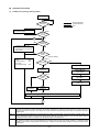
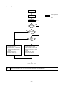
[2]
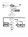
Operation Flow Chart
(1)
Outdoor unit (Cooling, heating modes)
Start
NO
Normal operations
Trouble observed
Stop
Breaker
turned on
YES
"HO" blinks on remote controller
temperature display
Note: 1
NO
Set indoor address No. to remote
controller
YES
2
NO
Operation
command
1. Protection function selfholding cancelled
2. Oil return LEV, SC coil LEV
fully closed
YES
Fan
Operation
mode
Cooling, Heating
1.
2.
3.
4.
52C
Inverter output
Fan stop
All solenoid valve
OFF
0Hz
Note: 2
Error mode
OFF
YES
NO
Error stop
52C ON
Outdoor unit LED
trouble display
Note: 3
Protection function
self-holding
Operation
mode
Error command to
indoor unit
Cooling
operations
Heating
operations
Operation mode command to indoor unit controller
2
Note: 1
For about 2 minutes after turning on power source, address and group information of outdoor unit, indoor unit, and remo te
controller are retrieved by remote controller, during which "HO" blinks on and off on remote controller. In case indoor unit is
not grouped to remote controller, "HO" display on remote controller continues blinking even after 2 minutes after turning on
power source.
Note: 2
Two trouble modes included indoor unit side trouble, and outdoor unit side trouble. In the case of indoor unit side trouble, error
stop is observed in outdoor unit only when all the indoor units are in trouble. However, if one or more indoor units are
operating normally, outdoor unit shows only LED display without undergoing stop.
Note : 3
Operation mode conforms to mode command by indoor unit. However, when outdoor unit is being under cooling operation,
the operation of indoor unit will be prohibited even by setting a part of indoor units under operation, or indoor unit under
stopping or fan mode to heating mode. Reversely when outdoor unit is being heating operation, the same condition will be
commenced.
- 31 -
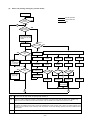
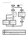
(2)
Indoor unit (Cooling, heating, dry, and fan modes)
Start
Normal operations
Breaker
turned on
Trouble observed
NO
Stop
YES
1
Operation
SW turned on
YES
NO
1. Protection function
self-holding cancelled
2. Indoor unit LEV fully
closed
Remote controller
display extinguished
Note: 2
Error mode
NO
YES
Operation mode
YES
1. Aux. heater
OFF
2. 1 minute low
FAN speed
Aux. heater
ON
Note: 4
NO
Error stop
Error display
Cooling
mode
Heating
mode
Dry mode
Fan mode
Protection function
self-holding
Cooling
display
Heating
display
Dry display
Fan displays
FAN stop
YES
Drain pump
ON
Error command
to outdoor unit
Prohibition
NO
Note: 1
Prohibition
NO
Indoor unit LEV
fully closed
3-minute drain
pump ON
YES
Cooling
operations
Note: 3
Note: 3
Note: 3
YES
Prohibition
NO
Heating
operations
YES
NO
Dry
operations
Fan
operations
Prohibition
"Remote controller blinking"
2
1
Note : 1
At indoor unit LEV fully closed, the opening angle indicates 41.
Note : 2
The error mode includes that of indoor unit and that of outdoor unit. In the former case, the indoor unit in question only
stops in error mood, while in the later case, all indoor units connected to the outdoor unit stop in error mode.
Note: 3
The operation mode follows the mode command from the indoor unit. However, when the outdoor unit is under cooling
operation, the operation of the indoor unit will be prohibited even a part of indoor units or indoor unit under stopping or fa n
mode is put into heating mode. Contrarily, when the outdoor unit is under heating operation, the same condition will be
commenced.
Note: 4
The auxiliary heater can only be equipped to the product of special specification.
- 32 -
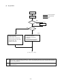
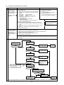
(3)
Cooling operation
Cooling operation
Normal operations
4-way valve OFF
Test run
Stop
Indoor unit fan
operations
Test run start
Note: 1
YES
NO
NO
Thermostat ON
YES
YES
3-minute
restart prevention
NO
1. Inverter output 0Hz
2. Indoor unit LEV, oil return LEV,
Subcool coil bypass LEV fully
closed
3. Solenoid valve OFF
4. Outdoor unit fan stop
1. Inverter frequency control
2. Indoor unit LEV, oil return LEV,
Subcool coil bypass LEV fully
closed
3. Solenoid valve control
4. Outdoor unit fan control
2 : (6) 1 or 3 : (6) 2
Note : 1
Indoor unit fan operates at set notch in cooling operation regardless of thermostat ON/OFF.
- 33 -
(4)
Heating operation (Only for PUHY)
Normal operations
Defrosting operations
Stop
Test run
Heating operation
Note: 1
Note: 2
Defrosting
operation
YES
4-way valve OFF
4-way valve ON
Test run start
YES
NO
NO
Thermostat ON
YES
YES
1. Indoor unit fan stop
2. Inverter defrost frequency control
3. Indoor unit LEV fully opened,
oil return LEV fully closed,
Subcool bypass LEV fully opened
4. Solenoid valve control
5. Outdoor unit fan stop
3-minute
restart prevention
NO
Note: 1
Note: 2
Defrosting
finish
NO
YES
1. Indoor unit fan very low speed
operations
2. Inverter output 0Hz
3. Indoor unit LEV, oil return LEV,
Subcool bypass LEV fully closed
4. Solenoid valve OFF
5. Outdoor unit fan stop
1. Indoor and outdoor unit fan
control
2. Inverter frequency control
3. Indoor unit LEV, oil return LEV,
Subcool bypass LEV control
4. Solenoid valve control
Defrosting finish
1 : (6) 4 or 3 : (6) 2
Note : 1
When outdoor unit starts defrosting, it transmits defrost operations command to indoor unit, and the indoor unit starts
defrosting operations.
Similarly when defrosting operation stops, indoor unit returns to heating operation after receiving defrost end command of
outdoor unit.
Note : 2
Defrosting start condition :
Defrosting end condition :
After integrated 50 minutes of compressor operations, and –2˚C or less outdoor unit coil
temperature.
After 15 minutes of defrosting operation or the outdoor unit coil temperature having risen to 12˚C
(80TMU), 8˚C (100TMU) or more for 80TMU and 100TMU.
- 34 -
(5)
Dry operation
Dry operations
Normal operations
Thermostat ON
4-way valve OFF
Stop
Test run start
YES
Note: 2
Thermostat ON
NO
NO
> 18˚C
Inlet temp.=
YES
Note: 1
1. Indoor unit fan stop
2. Inverter output 0Hz
3. Indoor unit LEV, oil return LEV,
Subcool bypass LEV fully closed
4. Solenoid valve OFF
1. Outdoor unit (Compressor)
intermittent operations
2. Indoor unit fan intermittent
YES
operations
(Synchronized with compressor :
low speed, OFF operations)
5. Outdoor unit fan stop
2 : (6) 1 or 3 : (6) 2
Note : 1
When indoor unit inlet temperature exceeds 18˚C, outdoor unit (compressor) and indoor unit fan start intermittent operations
synchronously. Operations of outdoor unit, indoor unit LEV and solenoid valve accompanying compressor are the same as
those in cooling operations.
Note : 2
Thermostat is always kept on in test run, and indoor and outdoor unit intermittent operation (ON) time is a little long er than
normal operations.
- 35 -
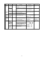
[3]
List of Major Component Functions
Name
Symbol
(function)
Part code
Application
Compressor
MC
Adjust refrigerant circulation by controlling operating frequency and capacity control valve with operating
pressure.
Pressure
sensor
63HS
1) High press. detection.
2) Frequency control and high pressure protection
Pressure
switch
63H
Thermistor TH1
(discharge)
TH2
(low pressure
saturation
temperature)
TH5
(piping
temperature)
TH6
(outdoor air
temperature)
TH7
(subcool coil
outlet temperature)
Check method
Low pressure shell scroll
type with capacity control
mechanism
Winding resistance:
Each phase 0.107Ω (20˚C)
63HS
Connector
Pressure
0~30 kg/cm2G
Vout 0.5~3.5 V
Gnd (black)
Vout (white)
Vcc (DC5V)
(red)
1) High pressure detection
2) High pressure protection
Setting 30kg/cm2G OFF
Continuity check
1) Discharge temperature detection
2) High pressure protection
R120=7.465kΩ
B25/120=4057
Resistance value
check
20˚C (68˚F)
30˚C (86˚F)
40˚C (104˚F)
50˚C (122˚F)
60˚C (140˚F)
Outdoor unit
Specification
: 250kΩ
: 160kΩ
: 104kΩ
: 70kΩ
: 48kΩ
70˚C (158˚F)
80˚C (176˚F)
90˚C (194˚F)
100˚C (212˚F)
110˚C (230˚F)
:
:
:
:
:
34kΩ
Rt =
24kΩ
7.465exp{4057( 1 – 1 )}
17.5kΩ
273+t 393
13.0kΩ
9.8kΩ
1) Detects the saturated vapor temperature.
2) Calculates the refrigerant
circulation configuration.
3) Controls the compressor
frequency.
4) Controls the outdoor unit’s fan air
volume.
Resistance value
R0=33kΩ
check
B0/100=3965
Rt =
1
1
33exp{3965( 273+t – 273+0 )}
-20˚C (-4˚F) : 92kΩ
-10˚C (14˚F) : 55kΩ
0˚C (32˚F) : 33kΩ
10˚C (50˚F) : 20kΩ
20˚C (68˚F) : 13kΩ
30˚C (86˚F) : 8.2kΩ
R0=15kΩ
1) Frequency control
2) Defrost control and liquid level de- B0/100=3460
Rt =
tection at heating
1
1
15exp{3460( 273+t – 273 )}
1) Outdoor air temperature detection
2) Fan control, liquid level heater, and
0˚C (32˚F)
: 15kΩ
opening setting for oil return
10˚C (50˚F) : 9.7kΩ
20˚C (68˚F) : 6.4kΩ
Subcool coil bypass LEV (LEV1) con25˚C (77˚F) : 5.3kΩ
trol
30˚C (86˚F) : 4.3kΩ
40˚C (104˚F) : 3.1kΩ
TH8
(subcool coil
bypass outlet
temperature)
Subcool coil bypass LEV (LEV1) control
THHS
1) Detects the inverter cooling fin
temperature.
2) Provides inverter overheating
protection.
3) Controls the control box cooling
fan.
- 36 -
R50=17kΩ
B25/50=4170
Rt =
-20˚C (-4˚F) :
-10˚C (14˚F) :
0˚C (32˚F)
:
10˚C (50˚F) :
20˚C (68˚F) :
30˚C (86˚F) :
40˚C (104˚F) :
50˚C (122˚F) :
60˚C (140˚F) :
70˚C (158˚F) :
80˚C (176˚F) :
90˚C (194˚F) :
100˚C (212˚F) :
605.0kΩ
323.3kΩ
180.9kΩ
105.4kΩ
63.8kΩ
39.9kΩ
25.7kΩ
17.0kΩ
11.5kΩ
8.0kΩ
5.7kΩ
4.1kΩ
3.0kΩ
Name
Solenoid
valve
Symbol
(function)
Application
Specification
SV1
(discharge suction bypass)
1) High/low press. bypass at starting/ AC 220V
stopping and capacity control at Open at energizing and
close at deenergizing
low load
2) Discharge press. rise suppression
SV2
(discharge suction bypass)
Capacity control and high press. rise AC 220V
suppression (backup for frequency Open at energizing and
close at deenergizing
control)
Electronic SLEV
expansion
valve
LEV1
(SC coil)
Indoor unit Outdoor unit
Part code
Adjustment of liquid refrigerant (oil)
return foam accumulator
Adjustment of bypass flow rate from
outdoor unit liquid line at cooling
Check method
Continuity check by
tester
DC12V stepping motor
drive Valve opening 0~480
pulse
Heating of refrigerant in accumulator
liquid level detection circuit
Resistance value
Cord heater : 2.8kΩ
(1.4kΩ+1.4kΩ) check
AC220V
20W (10W + 10W)
Electronic LEV
expansion
valve
1) Adjust superheat of outdoor unit
heat exchanger outlet at cooling.
2) Adjust subcool of indoor unit heat
exchanger at heating.
DC12V
Opening of stepping motor
driving valve
60~2,000 pulses
Thermistor TH21
(inlet air
temperature)
Indoor unit control (thermostat)
Resistance value
R0 = 15kΩ
check
B0/100 = 3460
Rt =
1
1
15exp{3460( 273+t – 273 )}
Liquid
level
detection
heater
CH2, CH3
(accumulator
liquid level
detection)
TH22
(piping
temperature)
1) Indoor unit control (freeze
prevention, hot adjust, etc.)
2) LEV control in heating operation
(Subcool detection)
TH23
(gas side
piping
temperature)
LEV control in cooling operation
(Superheat detector)
- 37 -
0˚C (32˚F)
10˚C (50˚F)
20˚C (68˚F)
25˚C (77˚F)
30˚C (86˚F)
40˚C (104˚F)
: 15kΩ
: 9.7kΩ
: 6.4kΩ
: 5.3kΩ
: 4.3kΩ
: 3.1kΩ
Continuity check
with tester for whitered-orange
yellow-brown-blue
[4] Resistance of Temperature Sensor
Thermistor for low temperature
Thermistor Ro= 15kΩ ± 3% (TH5 ~ 8)
1
1
)}
Rt = 15exp {3460 (
273+tc
273+0
9
∗˚F= × ˚C + 32
Thermistor R120 = 7.465kΩ ± 2% (TH1)
1
1
Rt = 7.465exp {4057 ( 273+tc - 273+120 )}
9
∗˚F= × ˚C + 32
5
Resistance (kΩ)
Resistance (kΩ)
5
Temperature (˚C)[˚F]
Temperature (˚C)[˚F]
Thermistor Ro = 33kΩ ± 1% (TH2)
1
1
Rt = 33exp {3965 ( 273+tc - 273+0 )}
9
∗˚F= × ˚C + 32
Thermistor R50 = 17kΩ ± 2% (THHS)
1
1
Rt = 17exp {4170 (273+tc - 273+50 )}
9
∗˚F= × ˚C + 32
5
Resistance (kΩ)
Resistance (kΩ)
5
Temperature (˚C)[˚F]
Temperature (˚C)[˚F]
- 38 -
5 REFRIGERANT AMOUNT ADJUSTMENT
Clarify relationship between the refrigerant amount and operating characteristics of CITY MULTI, and perform service
activities such as decision and adjustment of refrigerant amount on the market.
[1] Refrigerant Amount and Operating Characteristics
The followings are refrigerant amount and operating characteristics which draw special attention.
1
During cooling operations, required refrigerant amount tends to increase (refrigerant in accumulator decreases)
in proportion to increase in the number of operating indoor units. However, the change of increase rate is small.
2
During heating operations, liquid level of accumulator is the highest when all the indoor units are operating.
3
Discharge temperature hardly changes when increasing or decreasing refrigerant amount with accumulator
filled with refrigerant.
During cooling operations, discharge temperature tends to rise at
overload than low temperature.
4
Tendency of
discharge
temperature
During heating operations, discharge temperature tends to rise at low Comparison including
temperature than overload.
control system
The lower the operating frequency is, the higher the discharge
temperature tends to become of deteriorated compressor efficiency.
5
Compressor shell temperature is 20~70 (36~126) degrees higher than low pressure saturation temperature
(Te) when refrigerant amount is appropriate.
→ Judged as over replenishment when temperature difference from low pressure saturation temperature (Te)
is 10 (18) degrees or less.
Note : ˚C Scale (˚F Scale)
[2] Adjustment and Judgement of Refrigerant Amount
(1) Symptom
The symptoms shown in the table below are the signs of excess or lack of refrigerant amount. Be sure to adjust the
amount of refrigerant in refrigerant amount adjustment mode, by checking operation status, judging refrigerant
amount, and performing selfdiagnosis with LED Dip s/w 1, 1-10, for overall judgement of excess or lack of refrigerant amount.
1
Emergency stop at 1500 remote controller display (excessive
refrigerant replenishment)
2
Operating frequency does not fully increase, thus resulting in
insufficient capacity
3
Emergency stop at 1102 remote controller display (discharge
temperature trouble)
4
Emergency stop occurs when the remote control display is at
1501. (insufficient refrigerant)
Excessive refrigerant replenishment
Insufficient refrigerant replenishment
- 39 -
Insufficient refrigerant
(2) Refrigerant Volume Adjustment Operation
1) Operating Characteristics Refrigerant Volume
Characteristic items related to operating characteristics and the refrigerant volume are shown below.
1
If the number of indoor units in operation increases during cooling, the required volume of refrigerant tends to
increase (the amount of refrigerant in the accumulator tends to decrease), but the change is minimal.
2 The liquid level in the accumulator is at its highest when all the indoor units are operating during heating.
3 If there is refrigerant in the accumulator, even if the volume of refrigerant is increased or decreased, there is practically no change in the outlet temperature.
During cooling, the discharge temperature rises more easily when there is an
overload than when the temperature is low.
Tendency of
4 discharge
Temperature
During heating, the discharge temperature rises more easily when the temperature is low than when there is an overload.
Comparison
when control is
included.
The lower the operating frequency, the less efficient the compressor is, making it
easier for the discharge temperature to rise.
5 The compressor shell temperature becomes 20~70 (36~126) deg. higher than the low pressure saturation temperature (TH2) if the refrigerant volume is appropriate. If the difference with the low pressure saturation temperature
(TH2) is 10 (18) deg. or less, it can be judged that the refrigerant is overcharged.
Note : ˚C Scale (˚F Scale)
2) Adjusting and Judging the Refrigerant Volume
1 Symptoms
Overcharging with refrigerant can be considered as the cause of the following symptoms. When adjusting the
refrigerant volume, be sure that the unit is in the operating condition, and carry out refrigerant volume judgment and
self-diagnosis by the LED’s, judging overall whether the volume of refrigerant is in excess or is insufficient. Perform
adjustments by running the unit in the refrigerant volume adjustment mode.
1
Emergency stop occurs when the remote control display is at 1500 (refrigerant
overcharge).
Refrigerant overcharge
2 The operating frequency doesn’t rise high enough and capacity is not achieved.
3 Emergency stop occurs when the remote control display is at 1102 (outlet
temperature overheating).
4 Emergency stop occurs when the remote control display is at 1501 (insufficient
refrigerant).
Insufficient refrigerant
Insufficient refrigerant
2 Refrigerant Volume
a Checking the Operating Condition
Operate all the indoor units on cooling or on heating, checking the discharge temperature, sub-cooling, low pressure saturation temperature, inlet temperature, shell bottom temperature, liquid level, liquid step, etc. and rendering
an overall judgment.
Condition
Judgement
1
Outlet temperature is high. (125°C (257˚F) or higher)
2
Low pressure saturation temperature is extremely low.
3
Inlet superheating is high (if normal, SH = 20 (36) deg or lower).
4
Shell bottom temperature is high (the difference with the low pressure saturation
temperature is 70 (126) deg. or greater)
5
Shell temperature is low (the difference with the low pressure saturation temperature is 10 (18) deg. or lower).
6
Dischange superheating is low (if normal, SH = 20 (36) deg or higher).
Note : ˚C Scale (˚F Scale)
- 40 -
Refrigerant volume tends toward
insufficient.
Rifrigerant volume tends toward
overcharge.
b
Check the refrigerant volume by self-diagnosis using the LED.
Set the self-diagnosis switch (SW1) as shown below and check the past information (history) concerning the
refrigerant volume.
1 2 3 4 5 6 7 8 9 10
Set SW1 as shown in he figure at right.
ON
If LD8 lights up, it indicates the refrigerant charge abnormal delay state just before emergency stop due to refrigerant overcharge (1500).
3 Additional Refrigerant Charge Volume
At the time of shipping from the factory, the outdoor unit is charged with the amount of coolant shown in the following table, but since no extension piping is included, please carry out additional charging on-site.
Outdoor Unit Model Name
Refrigerant Charge Volume
PUHY-80TMU-A
6.5kg
(14lb 6oz)
PUHY-100TMU-A
9kg
(19lb 14oz)
Calculation Formula
Calculate the additional refrigerant volume by calculating the size of the extension liquid piping and its length units (m)[ft].
Additional Refrigerant Volume
(kg) = (0.12 × L1) + (0.06 × L2) + (0.024 × L3) + A
[ (oz) = (1.29 × L1) + (0.65 × L2) + (0.26 × L3) + A ]
L1:
L2:
L3:
A:
Length of ø12.7 (3/4") liquid pipe (m) [ft]
Length of ø9.52 (3/8") liquid pipe (m) [ft]
Length of ø6.35 (1/4") liquid pipe (m) [ft]
refer to the calculation table.
In the calculation results, round up fractions smaller than 0.01 kg. (Example: 18.54 kg → 18.6 kg)
1.0oz (653.97oz → 654oz)
(Calculation Table)
Total Capacity of
Connected Indoor Units
~64
65~
A
kg (oz)
1.5 (53)
2.0 (71)
- 41 -
3) Refrigerant Volume Adjustment Mode Operation
1 Procedure
Depending on the operating conditions, it may be necessary either to charge with supplementary refrigerant, or to
drain out some, but if such a case arises, please follow the procedure given below flow chart.
1
Switching the function select switch (SW2-4), located on the outdoor unit's control board, ON starts
refrigerant volume adjustment mode operation and the following operation occurs. (Refrigerant recovery
mode and oil recovery mode will be invalid.)
Operation
2
The outdoor unit LEV1 diverges more than usual during cooling operation.
Additionary, if the LED monitor display switch (SW1) on the outdoor unit's control board
is set to the composition of refrigerant circulating in the refrigeration cycle ( OC).
1 2 3 4 5 6 7 8 9 10
ON
Note 1: Even if the refrigerant volume has reached a suitable level shortly after starting refrigerant volume
adjustment mode, if left for a sufficient length of time (once the refrigeration system has stabilized), there
are times when this level may become unsuitable.
1) The refrigerant volume is suitable.
When the refrigerant volume for TH5-TH7 is more than 5K at the outdoor unit, and 6 to 13K for SH at
the indoor unit.
2) The current volume is suitable, however, may become unsuitable after a certain length of time.
When the refrigerant volume for TH5-TH7 is less than 5K at the outdoor unit, or less than 6K for SH at
the indoor unit.
Note 2: There are times when it becomes difficult to determine the volume when performing refrigerant
adjustments if the high pressure exceeds 1.37MPa.
Note 3: Based on the following flowchart, use TH1, TH5, TH7 and Tc to adjust the refrigerant volume. Use the
self-diagnosis switch (SW1) on the outdoor unit main PCB to display TH1, TH5, TH7 and Tc.
TH1 Self-diagnosis Switch
TH5 Self-diagnosis Switch
1 2 3 4 5 6 7 8 9 10
ON
1 2 3 4 5 6 7 8 9 10
ON
TH7 Self-diagnosis Switch
Tc Self-diagnosis Switch
1 2 3 4 5 6 7 8 9 10
ON
1 2 3 4 5 6 7 8 9 10
ON
Measure
Using these, judge TH1, Tc - TH5 and Tc - TH7.
When running refrigerant volume adjustment mode in the cooling operation, if note 2 above applies,
A determine the suitable refrigerant volume after waiting until outdoor units TH 5-7 reach
more than 5K, and the indoor unit SH is in the range of 6 to 9K.
C Turn on the outdoor unit self-diagnosis switch and then monitor the LED for the indoor unit SH.
- 42 -
Refrigerant adjustment method
Start
= Yes
Note 1, Operated using outdoor unit DIP SW3-1 and 3-2.
Note 2 , Ensure that no refrigerant is released into the
atmosphere
Note 3 , Always charge the system with liquid
refrigerant, if the system is charged with
gas the composition will change and
capacity will be reduced
= No
All indoor units are run in
test cooling mode
Note 1
Wait for 30minutes of
compressor operation
Note 4 , K = Degrees Kelvin
273K = 0°C
Minimum of
30minutes
continuous
operation
Wait 5minutes before making next judgment.
Add a small amount of
refrigerant to the low
pressure service port.
TH1 equal or
less than
115°C
Power supply to outdoor unit
has been on for 8 hours
or
30minutes of compressor running
and a stable compressor
frequency.
Wait 5minutes before making next judgment.
Wait 5minutes before making next judgment
Tc-TH5 is less than or
equal to 10K and
greater than or equal
to 3K
Tc-TH5 is less
than 3K
Add a small amount of
refrigerant at low pressure
service port.
Add asmall amount of
refrigerant at the low pressure
service port.
Tc-TH7 is greater
than or equal to
20K
Add a small amount of
refrigerant at low pressure
service port.
TH1 equal or less
than 110°C
System has the correct
amount of refrigerant
FINISH
- 43 -
Remove a small amount of
refrigerant at lowpressure
service port.
6 TROUBLESHOOTING
[1] Principal Parts
Pressure Sensor
(1) Judging Failure
1) Check for failure by comparing the sensing pressure according to the high pressure sensor and the pressure gauge
pressure.
Turn on switches 1, 3, 5, 6 of the digital display select switch (SW1) as shown below, and the sensor pressure of the
high pressure sensors is displayed digitally by the light emitting diode LD1.
1 2 3 4 5 6 7 8 9 10
High Pressure
ON
1
In the stopped condition, compare the pressure readings from the gauge and from the LD1 display.
(a) If the gauge pressure is 0~0.098MPa (0~14.2 psi), the internal pressure is dropping due to gas leakage.
(b) If the pressure according to the LD1 display is 0~0.098MPa (0~14.2 psi), there is faulty contact at the connector, or it is disconnected. Proceed to 4.
(c) If the pressure according to the LD1 display is 3.14MPa (455 psi) or higher, proceed to 3.
(d) If other than (a), (b) or (c), compare the pressure readings during operation. Proceed to 2.
2
Compare the pressure readings from the gauge and from the LD1 display while in the running condition.
(a) If the difference between the two pressures is within 0.098MPa (14.2 psi), both the affected pressure sensor
and the main MAIN board are normal.
(b) If the difference between the two pressures exceeds 0.098MPa (14.2 psi), the affected pressure sensor is faulty
(deteriorating performance).
(c) If the pressure reading in the LD1 display does not change, the affected pressure sensor is faulty.
3
Disconnect the pressure sensor from the MAIN board and check the pressure according to the LD1 display.
(a) If the pressure is 0~0.098MPa (0~14.2 psi) on the LD1 display, the affected pressure sensor is faulty.
(b) If the pressure is 3.14MPa (455 psi) or higher, the MAIN board is faulty.
4
Disconnect the pressure sensor from the MAIN board and short out the No. 2 and No. 3 pins of the connector
(63HS), then check the pressure by the LD1 display.
(a) If the pressure according to the LD1 display is 3.14MPa (455 psi) or higher, the affected pressure sensor
is faulty.
(b) If other than (a), the MAIN board is faulty.
2) Pressure sensor configuration.
The pressure sensors are configured in the circuit shown in the figure at right. If DC 5 V is applied between the red
and black wires, a voltage corresponding to the voltage between the white and black wires is output and this voltage
is picked up by the microcomputer. Output voltages are as shown below.
High Pressure
0.1 V per 0.098MPa (14.2 psi)
63HS
Vout 0.5~3.5 V
Connector
GND (Black)
Vout (White)
Vcc (DC5V) (Red)
- 44 -
✻Connector connection specifications on the pressure sensor body side.
The connector’s pin numbers on the pressure sensor body side differ from the pin numbers on the main circuit board side.
Sensor Body Side
Pin 1
Pin 2
Pin 3
Vcc
Vout
GND
MAIN Board Side
Pin 3
Pin 2
Pin 1
Solenoid Valve (SV1, SV2)
Check if the control board’s output signals and the operation of the solenoid valves match.
Setting the self-diagnosis switch (SW1) as shown in the figure below causes the ON signal of each relay to be output to the
LED’s.
Each LED shows whether the relays for the following parts are ON or OFF. When a LED lights up, it indicates that the relay
is ON.
SW1
1 2 3 4 5 6 7 8 9 10
ON
LED
1
2
3
4
5
Compressor
operating.
Crankcase
Heater
21S4
SV1
SV2
6
7
8
Lights up
all the
time.
CH 2, 3
Fluid
Level
Heater
1 2 3 4 5 6 7 8 9 10
ON
1) In the case of SV1 (Bypass Valve)
(a) When the compressor starts, SV1 is ON for 4 minutes, so check operation by whether the solenoid valve is emitting
an operating noise.
(b) Changes in the operating condition by solenoid valve operation can be confirmed by the temperature of the bypass
circuit and the sound of the refrigerant.
2) In the case of SV2 (Bypass)
(a) SV2 goes ON in accordance with the rise in the high pressure in the cooling mode and heating mode, so check its
operation by the LED display and the operating noise emitted by the solenoid valve.
(b) Changes in the operating condition by solenoid valve operation can be confirmed by the temperature of the bypass
circuit and the sound of the refrigerant.
- 45 -
Outdoor LEV
The valve opening angle changes in proportion to the number of pulses.
(Connections between the outdoor unit’s MAIN board and SLEV, LEV1 (outdoor electronic expansion valve))
Gray
Driver Circuits
Black
Yellow
Red
Orange
Outdoor MAIN Board
(Connectors CNLV1,
CNLV2)
Pulse Signal Output and Valve Operation
Output (Phase)
No.
ø1
ø2
ø3
ø4
Output State
1
2
3
4
5
6
7
8
ON OFF OFF OFF OFF OFF ON ON
ON ON ON OFF OFF OFF OFF OFF
OFF OFF ON ON ON OFF OFF OFF
OFF OFF OFF OFF ON ON ON OFF
Output pulses change in the following orders when the
Valve is Closed 1 → 2 → 3 → 4 → 5 → 6 → 7 → 8 → 1
Valve is Open
8→7→6→5→4→3→2→1→8
✻1. When the LEV opening angle does not change, all
the output phases are off.
2. When the output is out of phase or remains ON continuously, the motor cannot run smoothly, but move
jerkily and vibrates.
LEV Valve Closing and Valve Opening Operations
Valve Opening Angle (Flow Rate)
✻When the power is switched ON, a 520 pulse valve
opening signal is output to make sure the valve’s
position, so that it is definitely at point A. (The pulse
signal is output for approximately 17 seconds.)
When the valve operates smoothly, there is no
sound from the LEV and no vibration occurs, but
when the valve is locked, it emits a noise.
Valve
Closing
✻ Whether a sound is being emitted or not can be de-
Valve Opening
termined by holding a screwdriver, etc. against it,
then placing your ear against the handle.
Fully Open
480 pulses
✻If there is liquid refrigerant inside the LEV, the sound
may become lower.
Pulse Count
- 46 -
Judgment Methods and Likely Failure Mode
Caution:
The specifications of the outdoor unit (outdoor LEV) and outdoor units (indoor LEV) differ. For this reason, there ar e
cases where the treatment contents differ, so follow the treatment specified for the appropriate LEV as indicated in the
right column.
Failure Mode
Microcomputer
Driver Circuit
Failure
Judgment Method
Treatment
Disconnect the control board connector and connect the
check LED as shown in the figure below.
In the case of driver circuit
failure, replace the indoor
unit’s control board.
Affected LEV
Indoor
When the base power supply is turned on, the indoor LEV
outputs pulse signals for 10 seconds.
If the LED does not light up, or lights up and remains on,
the driver circuit is abnormal.
Indoor
Outdoor
LEV mechanism
is locked.
If the LEV is locked up, the drive motor turns with no load
and a small clicking sound is generated.
Generation of this sound when the LEV is fully closed or
fully open is abnormal.
Replace the LEV.
The LEV motor
coils have a
disconnected
wire or is
shorted.
Measure the resistance between the coils (red - white, red
- orange, brown - yellow, brown - blue) using a tester.
They are normal if the resistance is within 150Ω ± 10%.
Replace the LEV coils.
Indoor
Measure the resistance between the coils (gray - orange,
gray - red, gray - yellow, gray - black) using a tester. They
are normal if the resistance is within 46Ω ± 3%.
Replace the LEV coils.
Outdoor
Fully Closed
Failure (valve
leaks)
If you are checking the indoor unit’s LEV, operate the indoor unit in fan mode and at the same time operate other
indoor units in the cooling mode, then check the piping
temperatures (liquid pipe temperatures) of the indoor unit
by the operation monitor through the outdoor unit controller board. When the fan is running, the linear expansion
valve is fully closed, so if there is leakage, the temperature
sensed by the thermistor (liquid pipe temperature sensor)
will become low. If the temperature is considerably low
compared to the remote control’s intake temperature display, it can be
judged that there is a fully closed failThermistor ure. In the case of minimal leakage, it
(TH21)
is not necessary to replace the LEV if
there are no other effects.
Linear
If there is a large amount of
leakage, replace the LEV.
Indoor
Expansion
Valve
Faulty wire
connections in
the connector or
faulty contact.
1 Check for pins not fully inserted on the connector and
check the colors of the lead wires visually.
2 Disconnect the control board’s connector and conduct
a continuity check using a tester.
- 47 -
Check the continuity at the
places where trouble is found.
Indoor
Outdoor
Outdoor LEV (SLEV, LEV1) Coil Removal Procedure (configuration)
As shown in the figure, the outdoor LEV is made in such a way that the coils and the body can be separated.
Coils
Body
Stopper
Indentation for
Stopper
(12 places
around the
circumference)
Lead Wires
<Removing the Coils>
Fasten the body tightly at the bottom (Part A in the figure) so that
the body will not move, then pull out the coils toward the top. If
they catch on the stopper and are difficult to take out, turn the
coils left and right until the stoppers are free from the stopper
indentations, then pull the coils out.
If you take out the coils only without gripping the body, undue
force will be applied to the piping and the pipe may be bent over,
so be sure to fasten the body in such a way that it will not move.
Part A
<Installing the Coils>
Fasten the body tightly at the bottom (Part A in the figure) so that
the body will not move, then insert the coils from the top, inserting
the coils’ stopper securely in one of the indentations on the body.
(There are four indentations for the stopper on the body around
its circumference, and it doesn’t matter which indentation is
used. However, be careful not to apply undue force to the lead
wires or twist them around inside the body.) If the coils are inserted without gripping the body, it may exert undue force on the
piping, causing it to become bent, so be sure to hold the body
firmly so that it won’t move when installing the coils.
Part A
- 48 -
Intelligent Power Module (IPM)
Measure resistances between each terminal of IPM with tester, and use the results for troubleshooting.
1
Focus on whether there is a complete open (∞Ω) state or short-circuit (~0Ω).
The measured resistance value is a guideline and may deviate slightly.
Measure between several similar measurement points.
If the value does not differ by more than double or half from the other points, then judge the state as OK.
2
Restrictions to applicable tester
Use a tester with an internal power of 1.5V or more.
❇
Battery type tester
A card tester with button battery has a low applied voltage, so the resistance value of the diode characteristics
cannot be measured correctly.
Use a measurement range that measures the low resistance when possible. An accurate measurement with less
fluctuation will be possible.
The measured values for troubleshooting are shown in the table below.
• External view
• Internal circuit diagram
P
3
2
U
W
V
N
5
8
7
4
Pre-Driver
V
4
9
B
10
U
1
6
P
16
Pre-Driver
Pre-Driver
W
7
1
11
13
Pre-Driver
10
• Judged value
14
Tester
Black
Tester
Red
P
N
U
V
W
5~
5~
5~
200Ω 200Ω 200Ω
P
∞
N
U
∞
V
∞
W
∞
∞
Pre-Driver
∞
15
Pre-Driver
B
12
5~
200Ω
5~
200Ω
5~
200Ω
N
16
Over heating
protection circuit
Temperature sensor
Diode stack
Perform continuity check with tester. Judged as normal if the following characteristics are observed.
(Restrictions to applicable tester are the same as those of IPM)
Tester
Black
Tester
Red
+
—
+
—
1
2
1
2
3
3
+
1
2
3
–
- 49 -
1
2
3
5~
5~
5~
200Ω 200Ω 200Ω
∞
∞
∞
∞
5~
200Ω
5~
200Ω
5~
200Ω
∞
∞
(5)
Trouble and remedy of remote controller
Symptom
1
Cause
Despite pressing of
remote controller
switch, operation
does not start with no
electronic sound.
(No powering signal
appears.)
2
At about 10 seconds
after turning remote
controller operation
switch ON, the
display distinguishes
and the operation
stops.
Checking method & countermeasure
1) M-NET transmission power source is not supplied a) Check transmission terminal block of refrom outdoor unit.
mote controller for voltage.
1Main power source of outdoor unit is not connected.
i) In case of 17 ~ 30V
2Slipping off of connector on outdoor unit circuit
→ Faulty network remote controller
board
ii) In case of less than 17V
Main board
: CNS1, CNVCC3
→ See “Transmission Power Circuit
INV board
: CNDC2, CNVCC2, CNL2
(30V) Check Procedure” on Page 54.
G/A board
: CNDC1
3Faulty power source circuit of outdoor unit
• Faulty INV board,
• Blown fuse (F01 on G/A board)
• Broken diode stack
• Broken resistor (R1) for rush current protection
2) Short circuit of transmission line
The cause of 2) and 3) is dis3) Erroneous wiring of M-NET transmission line at outdoor unit
played with self-diagnosis
1Transmission line disconnection or slipping off from terminal
LED for 7102 error.
block
2Erroneous connection of indoor/outdoor transmission line to
TB7
4) Slipping off of transmission wiring at remote controller
5) Faulty remote controller
1) Power source is not fed to indoor unit from transformer.
1Main power source of indoor unit is not turned on.
2Slipping off of connector (CND, CNT, CN3T) on indoor controller board
3Blown fuse on indoor controller board
4Faulty or disconnected transformer of indoor unit
5Faulty indoor controller board
3) Faulty outdoor control circuit board or being out of control
As normal transmission is failed between indoor and outdoor units, outdoor unit model can not be
recognized.
Checking method & countermeasure
Check indoor LED1
Check indoor unit
power source terminal
block voltage
208~230V?
Lighting?
Lighting
Extinguishing or
unable to confirm
NO
Check main power source
of power source wiring.
YES
Check 220V circuit for
short circuit and ground
fault.
YES
Improper connector
connection
Apply power
source again.
YES
Check fuse on circuit
board
Blown?
NO
Check connector slipping off (CND, CNT, CN3T)
Slipped off?
NO
Check transformer
resistance value
✻1
NO
Within rated?
YES
Check for the change of LED
display by operating dip switch
SW1 for self-diagnosis.
Check cause of transformer disconnection.
•Ground fault on circuit
board
•Ground fault on
sensor, LEV
Check self-diagnosis
function of outdoor unit
NO
Changed?
Check self-diagnosis function
after powering outdoor unit again.
Changed?
YES
YES
Faulty indoor
controller board
✻1 Check
Casual
trouble
NO
Faulty outdoor unit
control circuit board
Repair
faulty point.
the transformer in accordance with the “TROUBLE SHOOTING” in the indoor unit’s service handbook.
- 50 -
Symptom
3
Cause
“HO” display on remote controller does
not disappear and
switch is ineffective.
(Without using MELANS)
1) Outdoor unit address is set to “00.”
2) Erroneous address
1Address setting miss of indoor unit to be coupled with remote controller
(Remote controller is not set to - 100.)
2Address setting miss of remote controller
(Indoor unit is not set to + 100.)
3) Faulty wiring of transmission terminal block TB5 of indoor unit in the same group with remote controller
4) Centralized control SW2-1 of outdoor unit is turned ON.
5) Disconnection or faulty wiring of indoor unit transmission line
6) Disconnection between indoor unit M-NET transmission line terminal block (TB5) and connector CN2M
7) More than 2 sets of power supply connector (CN40) are inserted into centralized control transmission
line of outdoor unit.
8) Faulty outdoor unit control circuit board
9) Faulty indoor controller board
10) Faulty remote controller
(Interlocking control with MELANS)
11) No grouping registration from MELANS (Neglecting to set the relation between indoor unit and network remote controller)
12) Slipping off of centralized control transmission line (TB7) at outdoor unit
13) At system connected with MELANS, power supply connector (CN40) is inserted to centralized control transmission line of outdoor unit
Checking method & countermeasure
In case no MELANS used
Same symptom for all
units in a single refrigerant system?
NO
Confirm address of remote
controller with "HO" displayed
YES
Check outdoor
unit address
51 ~ 100?
NO
Address setting
miss of remote
controller
Outdoor unit
address setting miss
NO
YES
YES
Check address of
coupling indoor unit
Check centralized control
switch SW2-1 at outdoor unit
ON?
NO
Indoor unit + 100?
YES
Indoor address
setting miss
Switch setting
miss
Make it ON
→OFF
NO
Remote controller
–100?
YES
Check voltage of indoor unit MNET transmission terminal block
Faulty outdoor unit
control circuit board
Transmission line
wiring miss of indoor unit M-NET
NO
17 ~ 30V?
YES
Check connection between indoor unit M-NET transmission terminal block (TB5) and connector CN2M
Slipping off of
CN2M
connector
YES
Slipping off?
NO
Check Fresh Master SW3-1
Setting miss
of Fresh
Master SW3-1
Repair spot
in trouble
NO
ON?
YES
Faulty indoor controller board
or remote controller
In case with MELANS used
When MELANS is used, “HO” display on the remote controller will disappear at the group registration of the indoor unit and local
remote controller.
If “HO” does not disappear after the registration, check the items 12) ~ 14) in the Cause column.
- 51 -
Symptom
4
“88” appears on remote controller at the
registration and
access
remote controller
Cause
Checking method & countermeasure
[Generates at registration and confirmation]
1) Erroneous address of unit to be coupled
2) Slipping off of transmission line of unit to be
coupled (No connection)
3) Faulty circuit board of unit to be coupled
4) Installation miss of transmission line
a) Confirm the address of unit to be coupled.
b) Check the connection of transmission line.
c) Check the transmission terminal block voltage
of unit to be coupled
i) Normal if voltage is DC17 ~ 30V
ii) Check the item d) in case other than i).
[Confirmation of different refrigerant system controller]
5) Breaking of power source of outdoor unit to be
confirmed
6) Slipping off of centralized control transmission
line (TB7) of outdoor unit
7) Power supply connector (CN40) is not inserted
into centralized control transmission line in
grouping with different refrigerant system without using MELANS
8) More than 2 sets of power supply connector
are inserted into the centralized control transmission line of outdoor unit
9) In the system connected with MELANS, power
supply connector (CN40) is inserted into the
centralized control transmission line of outdoor
unit.
10) Short circuit of centralized control transmission
line
d) Confirm the power source of outdoor unit to be
coupled with the unit to be confirmed
e) Confirm that the centralized control transmission line (TB7) of outdoor unit is not slipped off.
f) Confirm the voltage of centralized control transmission line.
i) Normal in case of 10V ~ 30V
ii) Check the items 7) ~ 10) left in case that
other than i).
`
- 52 -
Transmission Power Circuit (30 V) Check Procedure
If “ ” is not displayed by the remote control, investigate the points of the trouble by the following procedure and correct it.
No.
Check Item
1
Disconnect the transmission line from TB3
and check the TB3 voltage.
2
3
4
5
6
7
Judgment
Response
DC24~30 V
Check the transmission line for the following, and
correct any defects.
Broken wire, short circuit, grounding, faulty
contact.
Except the above-mentioned
to No. 2
Check if the following connectors are
disconnected in the outdoor unit’s control
box.
MAIN Board: CNS1, CNVCC3
INV Board: CNVCC2, CNL2, CNDC2
Connector disconnected
Connect the connectors as shown on the electric
wiring diagram plate.
Except the above-mentioned
to No. 3
Disconnect the wires from CNVCC3 on the
Main board and check the voltage between
pins 1 and 3 on the wire side of the
CNVCC3.
Tester + .......... 1 pin
Tester - .......... 3 pin
DC24~30 V
Check the wiring between CNS1 and TB3 for the
following, and correct any defects.
Broken wire, short circuit, grounding, faulty
contact.
If there is no trouble, replace the Main board.
Except the above-mentioned
to No. 4
DC24~30 V
Check the wiring between CNVCC2 and
CNVCC3 for the following, and correct any
defects.
Broken wire, short circuit, grounding, faulty
contact.
Except the above-mentioned
to No. 5
Disconnect the wiring from CNL2 on the
INV board, and check the resistance at
both ends of choke coil L2.
0.5~2.5Ω
to No. 6
Except the above-mentioned
Replace choke coil L2.
Check the voltage between pins 1 and 3 of
CNDC2 on the INV board.
DC280~342 V
Replace the INV board.
Except the above-mentioned
to No. 7
0Ω
to No. 8
Except the above-mentioned
Replace F01
Disconnect the wiring from CNVCC2 on the
INV board and check the voltage between
pins 1 and 3 of CNVCC2.
Tester + .......... 1 pin
Tester - .......... 3 pin
Check the resistance at both ends of F01
on the G/A board.
8
Check the resistans at both ends of R1
20~24 Ω
Except the abovementioned
to No. 9
Replace R1
9
Chcke the DS
refer to "Judging Diode
stack Failure"
Except the above-mentioned
to No.10
Replace DS
10
Check the voltage between RS and T on
power supply terminal block TB1.
AC187~253 V
Check the wiring to TB1 for the following and
correct any defects.
Broken wire, faulty contact.
Except the above-mentioned
Check the power supply wiring and base power
supply, and correct any defects.
- 53 -
1)
Investigation of transmission wave shape/noise
Control is performed by exchanging signals between outdoor unit, indoor unit and remote controller by M-NET transmission. If noise should enter into the transmission line, the normal transmission will be hindered causing erroneous
operation.
Symptom caused by the noise entered into transmission line
Cause
Noise entered into
transmission line
Error code
Signal changes and is misjudged as the signal of other
address.
6600
Transmission wave shape changes to other signal due
to noise.
6602
Transmission wave shape changes due to noise, and can
not be received normally thus providing no reply (ACK).
6607
Transmission can not be made continuously due to the
entry of fine noise.
6603
Transmission can be made normally, but reply (ACK) or
answer can not be issued normally due to noise.
6607
6608
Method to confirm wave shape
No fine noise allowed
✻1
▼
VHL
▼
<with transmission>
▼
VBN
52µs
▼
52µs
52µs
▼
▼
Logical value "0"
▼
2)
Erroneous operation
52µs 52µs
Logical value "1"
▼
(6)
No fine noise allowed ✻1
<without transmission>
Check the wave shape of transmission line with an oscilloscope to confirm that the following
conditions are being satisfied.
1 The figure should be 104µs/bit ± 1%.
2 No finer wave shape (noise) than the transmission signal (52µs ± 1%) should be allowed. ✻1
3 The sectional voltage level of transmission signal should be as follows.
Logical value
Transmission line voltage level
0
VHL = 2.0V or more
1
VBN = 1.3V or less
✻1 However, minute noise from the DC-DC converter or inverter operation may be picked up.
- 54 -
3)
Checking and measures to be taken
(a) Measures against noise
Check the items below when noise can be confirmed on wave shape or the error code in the item 1) is generated.
Measures to be taken
1 Wiring of transmission and power lines
in crossing
Isolate transmission line from power line (5cm or more).
Never put them in a same conduit.
2 Wiring of transmission line with that of
other system in bundle
Wire transmission line isolating from other transmission line.
Wiring in bundle may cause erroneous operation like crosstalk.
3 Use of shield wire for transmission line
(for both indoor unit control and centralized control)
Use specified transmission wire.
Type
: Shield line CVVS/CPEVS
Wire diameter
: 1.25mm2 or more
4 Repeating of shield at the repeating of
transmission line with indoor unit
The transmission line is wired with 2-jumper system. Wire the
shield with jumper system as same for transmission line.
When the jumper wiring is not applied to the shield, the effect
against noise will be reduced.
5 Are the unit and transmission lines
grounded as instructed in the INSTALLATION MANUAL?
Connect to ground as shown in the INSTALLATION MANUAL.
6 Earthing of the shield of transmission
line (for indoor unit control) to outdoor
unit
One point earthing should be made at outdoor unit.
Without earthing, transmission signal may be changed as the
noise on the transmission line has no way to escape.
7 Arrangement for the shield of transmission line (for centralized control)
For the shield earth of the transmission line for centralized control, the effect of noise can be minimized if it is from one of the
outdoor units in case of the group operation with different refrigerant systems, and from the upper rank controller in case the
upper rank controller is used.
However, the environment against noise such as the distance of
transmission line, the number of connecting sets, the type of
connecting controller, and the place of installation, is different for
the wiring for centralized control. Therefore, the state of the
work should be checked as follows.
a) No earthing
• Group operation with different refrigerant systems
One point earthing at outdoor unit
• Upper rank controller is used
Earthing at the upper rank controller
b) Error is generated even though one point earth is being connected.
Earth shield at all outdoor units.
Check for earthing
Checking for wiring method
Items to be checked
Connect to ground as shown in the user’s manual.
(b)When the wave height value of transmission wave shape is low, 6607 error is generated, or remote controller is
under the state of "HO."
Items to be checked
Measures to be taken
8 The farthest distance of transmission
line is exceeding 200m.
Confirm that the farthest distance from outdoor unit to indoor
unit/remote controller is less than 200m.
9 The types of transmission lines are different.
Use the transmission wire specified.
Type of transmission line
: Shield wire CVVS/CPEVS
Wire dia.of transmission line: 1.25mm2 or more
; No transmission power (30 V) is being
supplied to the indoor unit or the remote
control.
Refer to “Transmission Power Supply (30 V) Circuit Check Procedure.”
A Faulty indoor unit/remote controller
Replace outdoor unit circuit board or remote controller.
- 55 -
4)
No.
1
Treatment of Inverter and Compressor Troubles
If the compressor does not work when error codes 4240 or 4250 are detected, determine the point of malfunction
by following the steps in the appropriate sections on the pages starting from page 75, then perform the procedures
below.
Check Item
How many hours was the
power kept on before
operation?
Symptoms
Treatment
1 If it was kept on for 2 hours or longer
as specified
Go to [2].
2 It was kept on for less than the
specified period.
Go to [2] after keeping the power on for the
specified time.
2
When it is restarted, does the
trouble reappear?
1 The inverter stops and the same
error code is displayed.
Perform the check of wiring shown in the
explanation of each error code.
3
Run the outdoor unit with the
wiring to the compressor
disconnected. At this time,
change SW1-1 on the INV
board to ON.
Note) The terminals of the 3
disconnected wires
should be isolated from
each other.
1 The compressor stops and the same
error code is displayed.
Check the IPM is faulty. (Go to
“Individual Parts Failure Judgment Methods.”)
2 If the inverter’s output voltage is
output with good balance, ✻1
Check the coil resistance and insulation
resistance of the compressor, and if it is normal,
run it again, and if the trouble occurs again,
replace the compressor.
✻I nsulation resistance
: 1MΩ or more
Coil resistance
: 0.11Ω(20˚C)
3 If the balance in the inverter’s output
voltage is not good or if the inverter’s
output voltages are all 0 V (a digital
tester cannot be used) ✻1
Check the IPM
Judge that the IPM is faulty. (Go to “Individual
Parts Failure Judgment Methods.”)
If the IPM is normal, replace the INV board, then
perform this item again with SW1-1 ON. If the
problem is solved and you connect the
compressor again, turn SW1-1 OFF again.
Check the compressor’s coil resistance and
insulation resistance.
If the problem is not solved, replace the INV board.
✻1
[Cautions when measuring the voltage and current of the inverter’s power circuit.]
Since the voltage and current on the inverter’s power supply side and its output side do not have a sine waveform, the
measurement values will differ depending on the measuring instrument and the circuit measured.
In particular, as the inverter’s output voltage has a pulse waveform, the output frequency also changes, so differences in
measurement values will be great depending on the measuring instrument.
1 When checking if the inverter’s output voltage is unbalanced or not (relative comparison of the voltages between each
of the lines), if you are testing with a portable tester, be sure to use an analog tester.
Use a tester of a type which can be used to judge if the IPM or diode module is faulty.
In particular, in cases where the inverter’s output frequency is low, there are cases where the variations in measured
voltage values between the different wires will be great when a portable digital tester is used, when in actuality they are
virtually equal, and there is danger of judging that the inverter is faulty.
2 It is recommended when checking the inverter’s output voltage values (when measuring absolute values), that, if a
measuring device for business frequencies is used, a rectified voltage meter (with a
symbol) be used.
Correct measurement values cannot be obtained with an ordinary portable tester. (either analog or digital)
- 56 -
5) Troubleshooting at breaker tripping
Check items
Measures to be taken
1 Check the breaker capacity.
The breaker’s capacity should be proper.
2 Check the a short circuit or grounding in the electrical system other than the inverter.
Correct any defects.
3 Check the resistance between terminals on the terminal
block TB1 for power source.
Check each part inside the inverter power circuit (resistance, megohm or the like).
a) Diode stack
Refer to "Troubleshooting of diode stack."
b) IPM
Refer to "Troubleshooting of IPM."
c) Rush current protection resistor
d) Electromagnetic contactor
e) DC reactor
✻ For c) ~ e), refer to "Individual Parts Failure Judgement Methods."
1 0 ~ several ohms or improper megohm value
4 Checking by powering again.
1 Main power source circuit breaker tripping
2 No display of remote controller
5 O perational check by operating air conditioner
1 Normal operation without breaker tripping.
a) As there is a possibility of instantaneous short circuit generated, find the mark of the short circuit for
repair.
b) When a) is not applicable, the compressor may be
faulty.
2 Breaker tripping
The ground fault of inverter output/compressor can be
supposed.
Disconnect the wiring to the compressor and check the
insulation resistance of the following parts with a
megger.
a) Compressor terminals.
b) Inverter output.
- 57 -
6) Individual Parts Failure Judgment Methods.
Part Name
Judgment Method
Diode Stack (DS)
Refer to “Judging Diode Stack Failure.” (P49)
Intelligent Power Module (IPM)
Refer to “Judging IPM Failure.” (P49)
Electromagnetic Contactor (52C)
Measure the resistance value at each terminal.
Check Location
Judgment Value
0-1
50~100kΩ
2-4 6-8
∞
10-12 14-16
DC Reactor (DCL)
Measure the resistance between terminals: 1Ω or lower
Measure the resistance between the terminals and the chassis: ∞
Cooling Fan (MF1)
Measure the resistance between terminals: 0.1K~1.5KΩ
POWER board
Measure the resistance valve at between each terminal, and between
each terminal and case.
Check Location
Judgment Value
FN 3-6, FN 2-4
Under 1Ω
FN 1-2, FN 2-3,
FN4-6
∞
FN1, FN2, FN3,
FN4, FN6-Case
∞
[Caution at replacement of inverter parts]
1 The IPM and G/A board should be replaced together at the same time.
When the IPM is damaged, the G/A board may possibly be broken, and the use of the broken G/A board damages
the normal IPM. Therefore, replace the IPM and G/A board together at the same time. However, if the G/A board is
damaged, judge that the IPM is faulty, then judge whether replacement is necessary or not
2 Fully check wiring for incorrect and loose connection.
The incorrect or loose connection of the power circuit part wiring like IPM and diode module causes to damage the
IPM. Therefore, check the wiring fully. As the insufficient tightening of screws is difficult to find, tighten them
together additionally after finishing other works. For the wiring of the base for IPM, observe the wiring diagram
below carefully as it has many terminals.
3 Coat the grease for radiation provided uniformly onto the radiation surface of IPM/diode modules.
Coat the grease for radiation on the full surface in a thin layer, and fix the module securely with the screw for fastening.
As the radiation grease attached on the wiring terminal causes poor contact, wipe it off if attached.
- 58 -
Model PUHY-80TMU-A, 100TMU-A
To compressor
Red
White
Blue
Blue
Red
board
- 59 -
To capacitor (C1)
Check Code List
Check Code
Check Content
0403
Serial transmission trouble
0900
Trial operation
1102
Discharge temperature trouble
1111
Low pressure saturation temperature sensor trouble (TH2)
1302
High pressure trouble
1500
Refrigerant volume charge trouble
1505
Suction pressure trouble
2500
Leakage (water) trouble
2502
Drain pump trouble
2503
Drain sensor trouble
4102
Lacking power source error
4103
Reverse phase error/Lacking power source error
4115
Power supply sync signal trouble
4116
Fan speed trouble (motor trouble)
4200
VDC sensor/circuit trouble
4220
Bus voltage trouble
4230
Radiator panel overheat protection
4240
Overcurrent protection
4250
[1]
[11]
4260
IPM Alarm output/Bus voltage abnormality
IAC sensor overcurrent abnormality
Cooling fan trouble
Air inlet (TH21:IC)
5101
Discharge (TH1:OC)
Liquid pipe (TH22:IC)
5102
Low pressure saturation (TH2:OC)
5103
Thermal sensor
Gas pipe (TH23:IC)
5105
trouble
Liquid pipe (TH5)
5106
Ambient temperature (TH6)
5107
SC coil outlet (TH7)
5108
SC coil bypass outlet (TH8)
5110
Radiator panel (THHS)
5201
5301
Pressure sensor trouble
[6]
IAC sensor circuit/abnormality
[13]
IAC sensor miss-wiring abnormality
6600
Multiple address error
6602
Transmission processor hardware error
6603
Transmission circuit bus-busy error
6606
Communications with transmission processor error
6607
No ACK error
6608
No response error
7100
Total capacity error
7101
Capacity code error
- 60 -
Check Code
Check Content
6606
Communications with transmission processor abnormality
6607
No ACK abnormality
6608
No response abnormality
6831
MA communication, No-reception error
6832
MA communication, Synchronization recovery error
6833
MA communication, Transmission/reception handware error
6834
MA communication, Start bit error
7100
Total capacity abnormality
7101
Capacity code abnormality
7102
Connected unit count over
7105
Address setting abnormality
7106
Characteristics setting abnormality
7111
Remote control sensor abnormality
Intermittent fault check code
Trouble Delay Cope
Trouble Delay Content
1202 (1102)
1205
Preliminary discharge temperature abnormality or preliminary discharge thermal sensor abnormality (TH1)
Preliminary liquid pipe temperature sensor abnormality (TH5)
1211 (1111)
1214
Preliminary low pressure saturation abnormality or preliminary low pressure saturation sensor abnormality (TH2)
Preliminary THHS sensor/circuit abnormality
1216
Preliminary sub-cool coil outlet thermal sensor abnormality (TH7)
1217
Preliminary sub-cool coil bypass outlet thermal sensor abnormality (TH8)
1221
Preliminary ambient temperature thermal sensor abnormality (TH6)
1402 (1302)
Preliminary high pressure abnormality or preliminary pressure sensor abnormality
1600 (1500)
Preliminary overcharged refrigerant abnormality
1601
Preliminary lacked refrigerant abnormality
1605 (1505)
4300 (0403)
4300 (5301)
[9]
Preliminary suction pressure abnormality
Preliminary serial transmission abnormality
[6] IAC sensor/circuit abnormality
[13] IAC sensor miss-wiring abnormality
4310
Preliminary overcurrent breaking trouble
4320 (4220)
Preliminary bus voltage abnormality
4330 (4230)
4340 (4240)
4350 (4250) [1]
Preliminary heat sink overheating abnormality
Preliminary overload protection
IPM Alarm output/Bus voltage abnormality
[11] IAC sensor overcurrent abnormality
4360 (4260)
Preliminary cooling fan abnormality
Please refer to ( ) : Check Code. [ ] : Error detail No.
- 61 -
[2]
Self-diagnosis and Countermeasures Depending on the Check Code Displayed
(1)
Mechanical
Checking code
0403 Serial
transmission
trouble
Meaning, detecting method
If serial transmission cannot be
established between the MAIN
and INV boards
Cause
Checking method & Countermeasure
1) Wiring is defective.
Check 1, the connections, 2, contact
at the connectors and 3, for broken
wires in the following wiring.
CNRS2 - CNRS3
CNAC2 - TB1A
2) Switches are set wrong on the INV SW1-4 on the INV board should be
board.
OFF.
3) A fuse (F01) on the INV board is If the fuse is melted, (if the resisdefective.
tance between the both ends of fuse
is ∞), replace the fuse.
1102 Discharge
temperature
trouble
(Outdoor unit)
1. When 140°C or more discharge temperature is detected during op-erations
(the first time), outdoor unit
stops once, mode is
changed to restart mode after 3 minutes, then the outdoor unit restarts.
2. When 140°C or more temp.
is detected again (the second time) within 30 minutes
after stop of outdoor unit, error stop is observed with
code No. "1102" displayed.
3. When 140°C or more temp.
is detected 30 or more minutes after stop of outdoor
unit, the stop is regarded as
the first time and the process
shown in 1 is observed.
4. 30 minutes after stop of outdoor unit is intermittent fault
check period with LED displayed(1202).
4) The circuit board is defective.
If none of the items in 1) to 3) is applicable, and if the trouble reappears
even after the power is switched on
again, replace the circuit board by
the following procedure (when replacing the circuit board, be sure to
connect all the connectors, ground
wires, etc. securely).
1 If serial transmission is restored
after the INV board only is replaced, then the INV board is defective.
2 If serial transmission is not restored, reinstall the INV board
and replace the MAIN board. If
serial transmission is restored,
the MAIN board is defective.
3 If serial transmission is not restored by 1 and 2 above, replace both boards.
1) Gas leak, gas shortage
See Refrigerant amount check.
2) Overload operations
Check operating conditions and operation status of indoor/outdoor
units.
3) Poor operations of indoor LEV
4) Poor operations of OC controller
LEV
Cooling : LEV1
Check operation status by actually
performing cooling or heating operations.
Cooling : Indoor LEV
LEV1
Heating : Indoor LEV
See Trouble check of LEV and solenoid valve.
5) Poor operations of ball valve
Confirm that ball valve is fully
opened.
6) Outdoor unit fan block, motor Check outdoor fan.
trouble, poor operations of fan See Trouble check of outdoor fan.
controller→Heating
3) ~ 6) : Rise in discharge
temp. by low pressure drawing
7) Gas leak between low and high
pressures
4-way valve trouble, compressor
trouble, solenoid valve SV1
trouble
Check operation status of cooling or
heating.
8) Poor operations of solenoid valve
SV2
Bypass valve SV2 can not
control rise in discharge temp.
See Trouble check of solenoid
valve.
9) Thermistor trouble
Check resistance of thermistor
10)Thermistor input circuit trouble on
control circuit board
Check inlet temperature of sensor
with LED monitor.
- 62 -
Checking code
1111
Low
pressure
saturation
temperature
sensor
trouble
(TH2)
Meaning, detecting method
1. When saturation temperature sensor (TH2) detects
–40°C or less (the first time)
during operations, outdoor unit stops once,
mode is changed to restart
mode after 3 minutes, then
the outdoor unit restarts.
Cause
1) Gas leak, Gas shortage
See Refrigerant amount check.
2) Insufficient load operations
Check operating conditions and o p eration status of outdoor unit.
3) Poor operations of indoor LEV
4) Poor operations of OC controller
LEV1.
Check operation status by actually
performing cooling or heating operations.
Cooling : LEV1
Low pressure saturation temperature trouble
2. When –40°C or less temp. is
detected again (the second
time) within 30 minutes after
stop of outdoor unit, error
stop is observed with code
Nos. "1111" or displayed.
3. When –40°C or less temperature is detected 30 or
more minutes after stop of
outdoor unit, the stop is regarded as the first time and
the process shown in 1. is
observed.
4. 30 minutes after stop of outdoor unit is intermittent fault
check period with LED displayed.
Note:
1. Low press. saturation temperature trouble is not detected for 3 minutes after
compressor start, and finish of defrosting operations, and during defrosting operations.
2.In the case of short/open of
TH2 sensors before
starting of compressor or
within 10 minutes after
starting of compressor,
"1111" is displayed too.
Checking method & Countermeasure
Cooling : indoor LEV
LEV1
Heating : indoor LEV
See Trouble check of LEV and solenoid valve.
5) Poor operations of ball valve
Confirm that ball valve is fully
opened.
6) Short cycle of indoor unit
7) Clogging of indoor unit filter
8) Fall in air volume caused by dust
on indoor unit fan
9) Dust on indoor unit heat exchanger
10)Indoor unit block, Motor trouble
5)~10) : Fall in low press. caused
by lowered evaporating capacity in
cooling operation.
Check indoor unit, and take measures to troube
11)Short cycle of outdoor unit
12)Dust on outdoor heat exchanger
Check outdoor unit, and take measures to trouble
13)Indoor unit fan block, motor trouble,
and poor operations of fan controller
10)~12) : Fall in low press. caused by lowered evaporating capacity in heating operation.
Check outdoor unit fan.
See Trouble check of outdoor unit
fan.
14)Poor operations of solenoid valve
SV2
Bypass valve (SV2) can not
control low pressure drop.
See Trouble check of solenoid
valve.
15)Thermistor trouble (TH2~TH6)
Check resistance of thermistor
16)Pressure sensor trouble
See Trouble check of pressure
sensor.
17)Control circuit board thermistor
trouble and pressure sensor input
circuit trouble
Check inlet temp. and press. of sensor by LED monitor.
18)Poor mounting of thermistor
(TH2~TH6)
- 63 -
Checking code
Meaning, detecting method
1302 High pressure
trouble 1
(Outdoor unit)
1. When press. sensor detects
28kg/cm2 or more during operations (the first time), outdoor unit stops once, mode
is changed to restart mode
after 3 minutes, then the outdoor unit restarts.
Cause
1) Poor operations of indoor LEV
3. When 28kg/cm 2 or more
pres-sure is detected 30 or
more minutes after stop of
outdoor unit, the detection is
regarded as the first time
and the process shown in 1
is observed.
4. 30 minutes after stop of outdoor unit is intermittent fault
check period with LED displayed.
5. Error stop is observed immediately when press. switch
+ 0
(30 –1.5
kg/cm 2 ) operates in
addition to pressure sensor.
Check operations status by actually
performing cooling or heating operations.
Cooling : Indoor LEV
LEV1
Heating : Indoor LEV
2
2. When 30kg/cm or more
pres- sure is detected again
(the second time) within 30
minutes after stop of outdoor
unit,error stop is observed
with code No. "1302" displayed.
Checking method & Countermeasure
See Trouble check of LEV and solenoid valve.
2) Poor operations of ball valve
Confirm that ball valve is fully opened.
3) Short cycle of indoor unit
Check indoor unit and take mea4) Clogging of indoor unit filter
sures to trouble.
5) Fall in air volume caused by dust
on indoor unit fan
6) Dust on indoor unit heat exchanger
7) Indoor unit fan block, motor trouble
2)~7) : Rise in high pressure
caused by lowered condensing
capacity in heating operation
8) Short cycle of outdoor unit
Check outdoor unit and take mea9) Dust on outdoor unit heat ex- sures to trouble.
changer
10) Outdoor unit fan block, motor trou- Check outdoor unit fan
ble, poor operations of fan control- See Trouble check of outdoor unit
ler
fan.
8)~10) : Rise in high press. caused by lowered condensing capacity in cooling operation
11)Poor operations of solenoid valves See Trouble check of solenoid
SV1, 2 (Bypass valves (SV1, 2) can valve.
not control rise in high pressure)
12)Thermistor trouble (TH2, TH5, TH6)
Check resistance of thermistor.
13) Pressure sensor trouble
Check Trouble check of pressure
sensor.
- 64 -
Checking code
Meaning, detecting method
1302 High pressure
trouble 1
(Outdoor unit)
Cause
Checking method & Countermeasure
16)Control circuit board thermistor
trouble, press. sensor input circuit trouble
Check inlet temperature and press.
of sensor with LED monitor.
17)Poor mounting of thermistor
(TH2, TH5, H6)
18)Coming loose the connecter of
pressure switch or cut of the wire.
High pressure
trouble 2
(Outdoor unit)
1500 Overcharged
refrigerant
abnormality
When press. sensor detects
1kg/cm 2 or less just before
starting of operation, erro stop
is observed with code No.
"1302" displayed.
1. If the discharge SH<
=10K is
detected during operation (at
first detection), the outdoor
unit stops at once. The 3minute restart prevention
mode is entered. After three
minutes, the outdoor unit
starts up again.
2. If the discharge SH<
=10K is
detected again within 30
minutes after the outdoor unit
stops (second detection), an
abnormal stop is applied, and
"1500" is displayed.
3. If discharge SH<
=10K is
detected more than 30
minutes after the outdoor unit
stops, the state is the same
as the first detection and the
same operation as 1 above
takes place.
1) Fall in internal press. caused by
gas leak
2) Press. sensor trouble
3) Film breakage
4) Coming off of pin in connector
portion, poor contact
5) Broken wire
6) Press. sensor input circuit trouble
on control circuit board
See Trouble check of pressure
sensor.
1) Excessive refrigerant charge.
Refer to the section on judging the
refrigerant volume.
2) Main circuit board thermistor
input circuit trouble
Check the sensor detection
temperature and pressure with
the LED monitor.
3) Thermistor mounting trouble
(TH1, TH2)
4. The abnormal stop delay
period is in effect for 30
minutes after the outdoor unit
stops. The abnormal stop
delay period LED turns ON
during this time.
5. If the abnormality detection
prohibit switch (SW2-4) is
ON, the same operation as
the first detection will apply
for the second and following
detections.
1505 Suction
pressure
trouble
<Condition 1>
1. Judging that the state when
the suction pressure reaches
0kg/cm 2G during compressor operation indicates high
pressure by the discharge
temperature and low pressure saturation temperature,
the back-up control by gas
bypassing will be conducted.
2. The outdoor unit once stops
entering into the 3-minutes
restart mode if the state of 1
continues for 3 minutes, and
restarts after 3 minutes.
3. After restarting, if the same
state as 1 continues within
30 minutes from the stopping
of 2, error stop will be commenced displaying “1505”.
4. Ineffective if the compressor
operating time (integrated)
exceeds 60-minutes not detecting trouble.
•
•
•
Operation while neglecting to
open ball valve. Especially for the
ball valve at low pressure side.
At cooling : Gas side ball valve
At heating : Liquid side ball
valve
When plural systems are existing,
the low pressure abruptly drop at
indoor stopping by the erroneous
wiring of transmission line (different connection of transmission
line and refrigerant piping).
Temporary vacuum condition due
to refrigerant distribution unbalance (insufficient refrigerant of
low pressure line) immediately after charging refrigerant.
- 65 -
Once vacuum operation protection
is commenced, do not attempt to restart until taking the measures below.
<Checking method>
• Check ball valve for neglecting to
open.
• Check extended piping for clogging when ball valve is opened.
• Check transmission line for erroneous wiring. (Confirm the correct wiring and piping connection
between indoor and outdoor
units by operating indoor unit one
by one.)
<Countermeasure>
• After checking with the above
method, make error reset by
power source reset.
• Then operate for 10~15-minutes
under the operation mode reverse to that when the vacuum
operation protection occurred
(Heating if error occurred in cooling, while cooling if it occurred in
heating), and then enter into the
ordinary operation state.
Checking code
Meaning, detecting method
2500 Leakage
(water) trouble
When drain sensor detects
flooding during drain pump
OFF.
1) Water leak due to humidifier or the Check water leaking of humidifier
and clogging of drain pan.
like in trouble.
2502 Drain pump
trouble
The drain sensor's water drain*
and after the drain pump is turn
on for more than three minuites.
1) Drain sensor sinks in water be- Check operations of drain pump.
cause drain water level rises due to
drain water lifting-up mechanism
trouble.
✻ D rain sensor's water drain
condition when indirect heater
of drain after 40 second's.
• Rise in temperature of drain
sensor is 20 deg or less or
• The temperature of the
drain sensor is 63°C or less.
2503 Drain sensor
trouble
Short/open is detected during
drain pump operations. (Not detected when drain pump is not
operating.)
Short : 90°C or more detected
Open : –40°C or less detected
Cause
Checking method & Countermeasure
2) Broken wire of indirect heater of Measure resistance of indirect
heater of drain sensor.
drain sensor
(Normal: Approx. 82Ω between 1–3
of CN50)
3) Detecting circuit (circuit board)
trouble
Indoor LEV operation is faulty.
4) The trable of indoor LEV
Indoor board trouble if no other
problems is detected.
Operate in fan mode checking to
make sure that the temperature of
TH2 and TH3 rise to the around the
same level.
Check resistance of thermistor
1) Thermistor trouble
0°C : 15kΩ
10°C : 9.7kΩ
2) Poor contact of connector
20°C : 6.4kΩ 30°C : 4.3kΩ
(insufficient insertion)
40°C : 3.1kΩ
3) Full-broken of half-broken thermistor wire
4) Indoor unit circuit board (detecting Check contact of connector
Indoor port trouble if no other probcircuit) trouble
lem is detected.
2600 Water leak
trouble
—
Water leak from piping of humidifier
Confirm water leaking section.
2601 Water
suspension
trouble
—
1) Water is not supplied to water tank
for humidifying.
2) The solenoid valve for humidifying
is set to OFF.
3) Disconnection of float switch.
Confirm supply water volume.
Solenoid valve and connection
Confirm connector section.
4) Faulty operation of float switch.
5) Freezing of water tank.
Operation of
float switch
When Float switch operates
(point of contact : OFF), error
stop is observed with code No.
"2503" displayed.
Confirm connecting section.
Faulty float switch.
Turn power source OFF once, and
turn ON after thawaing.
1) Drain up input trouble
Check drain pump operations
2) Poor contact of float switch circuit
Check connect contact.
3) Float switch trouble
Check float switch operations.
- 66 -
Checking code
4102 Open phase
error
4103 Reverse
phase error
Meaning, detecting method
Open phase in the power system is being detected, so operation cannot be started.
Reverse phase (or open phase)
in the power system is being
detected, so operation cannot
be started.
Cause
Checking method & Countermeasure
1) Open phase has occurred in the Check before the breaker, after the
power supply (R, S, T).
breaker or at the power supply terminal blocks TB1, and if there is an
open phase, correct the connections.
a) Check if a wire is disconnected.
b) Check the voltage between
each of the wires.
2) The wiring is faulty.
Check 1 the connections, 2, the contact at the connector, 3, the tightening torque at screw tightening locations and 4 for wiring disconnections.
TB1~EN20
Refer to the circuit number and the
wiring diagram plate.
3) The fuse is faulty.
If F1, F2 or F3 on the MAIN board is
melted, (Resistance between both
ends of the fuse is ∞), replace the
fuses.
4) The circuit board is faulty.
If none of the items in 1) to 4) is applicable, and if the trouble reappears
even after the power is switched on
again, replace the MAIN board
(when replacing the circuit board, be
sure to connect all the connectors,
etc. securely).
1) The phases of the power supply (R, If there is reverse phase before the
S, T) have been reversed.
breaker, after the breaker or at the
power supply terminal blocks TB1,
reconnect the wiring.
2) Open phase has occurred in the Check before the breaker, after the
power supply (R, S, T).
breaker or at the power supply terminal blocks TB1, and if there is an
open phase, correct the connections.
a) Check if a wire is disconnected.
b) Check the voltage between
each of the wires.
3) The wiring is faulty.
Check 1 the connections, 2, the contact at the connector, 3, the tightening torque at screw tightening locations and 4 for wiring disconnections.
TB1~EN20
Refer to the circuit number and the
wiring diagram plate.
4) The fuse is faulty.
If F1 or F2 or F3 on the MAIN board
is melted, (Resistance between both
ends of the fuse is ∞), replace the
fuses.
5) The circuit board is faulty.
If none of the items in 1) to 4) is applicable, and if the trouble reappears
even after the power is switched on
again, replace the MAIN board
(when replacing the circuit board, be
sure to connect all the connectors,
etc. securely).
- 67 -
Checking code
4115 Power supply
sync signal
trouble
4116 Fan speed
trouble (motor
trouble)
Meaning, detecting method
The frequency cannot be determined when the power is
switched on.
(The power supply’s frequency
cannot be detected. The outdoor fan cannot be controlled
by phase control.)
(Detects only for PKFY-NAM)
1. Detecting fan speed below
180rpm or over 2000rpm
during fan operation at indoor unit (first detection) enters into the 3-minute restart
prevention mode to stop fan
for 30 seconds.
2. When detecting fan speed
below 180rpm or over
2000rpm again at fan returning after 30 seconsd from
fan stopping, error stop (fan
also stops) will be commenced displaying 4116.
Cause
Checking method & Countermeasure
1) There is an open phase in the Check before the breaker, after the
breaker or at the power supply terpower supply (R, S, T)
minal blocks TB1 or TB1A, and if
there is an open phase, correct the
connections.
2) The power supply voltage is dis- If the power supply voltage waveform is distorted from a sine wave,
torted.
improve the power supply environment.
3) A fuse is defective.
If F1, F2 or F3 on the MAIN board,
or F3 is melted, (Resistance
between both ends of the fuse is ∞),
replace the fuses.
4) The circuit board is defective.
If none of the items in 1) to 3) is applicable, and if the trouble reappears even after the power is
switched on again, replace the
MAIN board (when replacing the circuit board, be sure to connect all the
connectors, ground wires, etc. securely).
1) Slipping off of fan speed detecting •
connector (CN33) of indoor controller board
Confirm slipping off of connector
(CN33) on indoor controller
board.
2) Slipping off of fan output connector •
(FAN1) of indoor power board
Confirm slipping off of connector
(FAN1) on indoor power board.
3) Disconnection of fan speed detect- •
ing connector (CN33) of indoor
controller board, or that of fan output connector (FAN1) of indoor
powr board.
Check wiring for disconnection.
4) Filter cologging
•
Check filter.
5) Trouble of indoor fan motor
•
Check indoor fan motor.
6) Faulty fan speed detecting circuit of •
indoor controller board, or faulty fan 1)
output circuit of indoor power
board.
When aboves have no trouble.
For trouble after operating fan.
Replace indoor controller board.
If not remedied, replace indoor
power board.
2) For trouble without operating fan.
Replace indoor power board.
- 68 -
Checking code
4200 VDCsensor/
circuit trouble
Meaning, detecting method
150 V is detected
1 If VDC
just before the inverter
starts.
2 If VDC
400 V is detected
just before the inverter
starts.
3 If the voltage of the INV
board’s sensor circuit input is
what it should not normally
be.
Cause
Checking method & Countermeasure
1) Power supply voltage is abnormal.
• Check if an instantaneous power
failure or power failure, etc. has occurred.
• Check if the voltage is the rated
voltage value.
2) The wiring is defective.
Check 1, the connections, 2, contact
at the connectors, 3 tightening
torque at screw tightened portions,
4, wiring polarities, 5, for broken
wires, and 6, for grounding in the following wiring.
TB1 ~ DS ~ POWER Board ~ 52C
~ R1 ~ DCL~C1 ~ IPM ~ G/A
Board (F1) ~ CNDC1 ~ CNDC2
wiring
✻ Check if the wiring polarities are as
shown on the electric wiring diagram plate.
3) The rush current prevention resistors (R1) are defective.
To judge failure of R1, go to “Individual Parts Failure Judgment Methods.”
4) The electromagnetic contactor
(52C) is defective.
To judge failure of the 52C, go to
“Individual Parts Failure Judgment
Methods.”
5) The diode stack (DS) is defective.
To judge failure of the DS, go to “Individual Parts Failure Judgment
Methods.”
6) The reactor (DCL) is defective.
To judge failure of the DCL, go to
“Individual Parts Failure Judgment
Methods.”
7) The INV board is defective.
If none of the items in 1) to 6) is applicable, and if the trouble reappears
even after the power is switched on
again, replace the INV board, (when
replacing the circuit board, be sure
to connect all the connectors, etc.
securely)
- 69 -
Checking code
4220 Bus voltage
trouble
4230 Radiator
panel
overheat
protection
Meaning, detecting method
If VDC 220 V is detected during inverter operation.
If the cooling fan stays ON for 5
minutes or longer during inverter operation, and if THHS
92 °C is detected.
Cause
Checking method & Countermeasure
1) The power supply voltage is abnormal.
• Check if an instantaneous stop or
power failure, etc. has occurred.
• Check if the voltage is the rated
voltage value.
2) The wiring is defective.
Check 1, the connections, 2, contact
at the connectors, 3 tightening
torque at screw tightened portions,
4, wiring polarities, 5, for broken
wires, and 6, for grounding in the following wiring.
TB1 ~ DS ~ Power Board ~ 52C
~ R1 ~ DCL ~ C1 ~IPM ~ G/A
Board (F1) ~ CNDC1 ~ CNDC2
Wiring
CN15V1 ~ CN15V2 Wiring
CNDR1 ~ CNDR2 Wiring
✻ Check if the wiring polarities are as
shown on the wiring diagram plate.
3) The rush current prevention resistors (R1) are defective.
To judge failure of R1, go to
“Individual Parts Failure Judgment
Methods.”
4) The electromagnetic contactor
(52C) is defective.
To judge failure of the 52C, go to
“Individual Parts Failure Judgment
Methods.”
5) The diode stack (DS) is defective.
To judge failure of the DS, go to “Individual Parts Failure Judgment
Methods.”
6) The reactor (DCL) is defective.
To judge failure of the DCL, go to
“Individual Parts Failure Judgment
Methods.”
7) The inverter output is grounded.
• Check the wiring between the IPM
and the compressor.
• Check the compressor’s insulation
resistance.
8) The capacitor (C1) is defective
Check the capacity of C1. (If
C1<
=3700 µF is defective )
9) The circuit board is defective.
If none of the items in 1) to 8) is applicable, and if the trouble reappears
even after the power is switched on
again, replace the INV board (when
replacing the circuit board, be sure
to connect all the connectors,
ground wires, etc. securely).
1) The wiring is defective.
Check 1 connections, 2 contact at
the connectors and 3 for broken
wires in the following wiring.
MF1~CNFAN
2) The INV board fuse (F01) is defective.
If the fuse is defective, replace the
fuse.
3) The cooling fan (MF1) is defective.
To judge failure of the MF1, go to
“Individual Parts Failure Judgment
Methods.”
4) The THHS sensor is defective.
To judge failure of the THHS, go to
error code “5110”.
5) The air passage is clogged.
If the air passage of the heat sink is
clogged, clear the air passage.
6) The INV board is defective.
If none of the items in 1) to 5) is applicable, and if the trouble reappears
even after the power is switched on
again, replace the INV board (when
replacing the circuit board, be sure
to connect all the connectors,
ground wires, etc. securely).
- 70 -
Checking code
4240 Overcurrent
protection
4250 Breaking of
overcurrent
Meaning, detecting method
If IDC 103 A is detected continuously for 10 minutes during
operation of the inverter after 5
or more seconds have passed
since the inverter started.
Cause
Checking method & Countermeasure
1) Air passage Short Cycle
Is the unit’s exhaust short cycling?
2) The heat exchanger is clogged.
Clean the heat exchanger.
3) Power Supply Voltage
If the power supply voltage is less
than 198 V, it is outside specifications.
4) External Air Temperature
If the external air temperature is
over than 43 °C it is outside the
specifications.
5) Capacity Setting Error
• Is the indoor unit capacity total appropriate?
• Are the outdoor/indoor unit capacity settings appropriate?
6) The THHS sensor is defective.
To judge failure of the THHS, go to
the item for error code “5110.”
7) The solenoid valves (SV1, 2) are
defective, or the solenoid valve
drive circuit is defective.
To judge failure of the solenoid valve, go
to “Individual Parts Failure Judgment
Methods” for the “Solenoid Valve.”
8) The wiring is defective.
Check 1 connections, 2 contact at
the connectors and 3 for broken
wires in the following wiring.
CNFAN1~MF1
9) Fan motor (MF) operation is defective.
Go to “Treating Fan Motor Related
Trouble.”
10)The inverter/compressor is defective.
Go to “Treating Inverter/Compressor
Related Trouble.”
11)The circuit board is defective.
If none of the items in 1) to 10) is applicable, and if the trouble reappears even
after the power is switched on again, replace the MAIN board (when replacing
the circuit board, be sure to connect all
the connectors, ground wires, etc. securely).
1) IPM/VDC trouble
1) Self protection by IPM break out, Go to the item for error code 4230,
(over current, over heat, under con- 4240.
trol voltage)
2) If IDC
200 A is detected
during inverter operation.
1) The power supply voltage is abnormal.
• Check if an instantaneous power
failure or power failure, etc. has occurred.
• Check if the voltage is the rated
voltage value.
2) The wiring is defective.
Check 1, the connections, 2, contact
at the connectors, 3 tightening
torque at screw tightened portions,
4, wiring polarities, 5, for broken
wires, and 6, for grounding in the following wiring.
✻ Check if the wiring polarities are as
shown on the wiring diagram plate.
✻ Check the coil resistances and insulation resistance of the compressor.
3) The inverter/compressor is defective.
Go to "Treatment of Inverter/Compressor Releated Trouble."
(the same as error code 4220)
Go to the item for error code 4220.
350V or VDC
3) If VDC
190V is detected during inverter operates.
- 71 -
Checking code
4260 Cooling fan
trouble
Meaning, detecting method
If the heat sink temperature
(THHS) 60°C for 10 minutes
or longer just before the inverter
starts.
5110 Radiator panel If a heat sink temperature of
(THHS) 40°C is detected just
before starting of, and during
operation of the inverter.
5301 IDC sensor/
circuit trouble
• If IDC 20 A is detected just
before the inverter starts, or
• If IDC 10 A is detected during inverter operation after 5
seconds has passed since the
inverter started when the INV
board’s SW1-1 is OFF.
Cause
Checking method & Countermeasure
1) Same as “4230.”
Same as “4230.”
1) The THHS Sensor is defective.
Judge that the THHS has failed. Go
to error code “5110.”
2) Contact is faulty.
Check the contacts of CNTH on the
INV board.
3) The INV board is defective.
If none of the items in 1) to 2) is applicable, and if the trouble reappears even after the power is
switched on again, replace the INV
board (when replacing the circuit
board, be sure to connect all the
connectors, ground wires, etc. securely).
1) Contact is faulty.
Check the contacts of CNCT on the
INV board.
2) The current sensor (DCCT) is connected with reverse polarity.
Check the DCCT polarity.
3) An error was made in the SW1-1
setting.
• With SW1-1 OFF, is the inverter’s
output wiring open?
• With SW1-1 OFF, is a compressor
which is not specified for this model
connected to the inverter’s output?
4) The INV board is defective. The
current sensor (DCCT) is defective.
If none of the items in 1) to 3) is applicable, and if the trouble reappears even after the power is
switched on again, replace the INV
board and the DCCT (when replacing the circuit board, be sure to connect all the connectors, ground
wires, etc. securely) by the following
procedure.
1 Replace the INV board only. If it
recovers, the INV board is defective.
2 If it does not recover, reinstall the
INV board and replace the DCCT.
If it recovers, the DCCT is defective.
If it does not recover after 1 and 2
above, both the INV board and the
DCCT are defective.
- 72 -
Checking code
5101
5105
5106
5107
5108
Thermal Sensor Error, Outdoor Unit
5102
Meaning, detecting method
Discharge <Other than THHS>
1 A short in the thermistor or
(TH1)
an open circuit was sensed.
The outdoor unit switches to
Low
the temporary stop mode
pressure
with restarting after 3 minsaturation
utes, then if the temperature
(TH2)
detected by the thermistor
just before restarting is in the
normal range, restarting
takes place.
2 If a short or open circuit in
the thermistor is detected
just before restarting, error
code “5101”, “5102”, “5105”,
“5106”, "5107", “5108” or
“5109” is displayed.
3 In the 3 minute restart mode,
the abnormal stop delay LED
Liquid
is displayed.
pipe (TH5)
4 The above short or open circuit is not detected for 10
Ambient
minutes after the comprestemperasor starts, or for 3 minutes
ture (TH6)
during defrosting or after recovery following defrosting.
SC coil
<THHS>
outlet
If a heat sink (THHS) tempera(TH7)
ture of -40 °C is detected just
after the inverter starts or during
SC coil
inverter operation.
bypass
outlet
(TH8)
5110
Radiator
panel
(THHS)
5201
Pressure
sensor
trouble
1 When pressue sensor detects 1kg/cm2 or less during
operation, outdoor unit once
stops with 3 minutes restarting mode, and restarts if the
detected pressure of pressure sensor exceeds 1kg/
cm 2 imediately before restarting.
2 If the detected pressure of
sensor is less than 1kg/cm2
immediately before restarting, error stop is commenced displaying 5201.
Cause
Checking method & Countermeasure
1) Thermistor
Check the thermistor’s resistance.
2) Lead wires are being pinched.
Check if the lead wires are pinched.
3) Insulation is torn.
Check for tearing of the insulation.
4) A connector pin is missing, or there
is faulty contact.
Check if a pin is missing on the connector.
5) A wire is disconnected.
Check if a wire is disconnected.
6) The thermistor input circuit on the
MAIN circuit board is faulty.
(In the case of the THHS, replace
the INV board.)
Check the temperature picked up by
the sensor using the LED monitor.
If the deviation from the actual temperature is great, replace the MAIN
circuit board.
(In the case of the THHS, replace
the INV board.)
Short Circuit Detection
TH1
TH2
TH3
TH4
TH5
TH6
TH7
TH8
THHS
240°C or higher (0.57 kΩ)
70°C or higher (1.71 kΩ)
70°C or higher (1.14 kΩ)
70°C or higher (1.14 kΩ)
110°C or higher (0.4 kΩ)
110°C or higher (0.4 kΩ)
70°C or higher (1.14 kΩ)
110°C or higher (0.4 kΩ)
100°C or higher (3.0 kΩ)
1) Pressutre sensor trouble.
2) Inner pressure drop due to a leakage
3) Broken cover.
4) Coming off of pin at connector portion, poor contact.
5) Broken wire
6) Faulty thermistor input circuit of
MAIN board.
3 Under 3 minutes restarting
mode, LED displays intermittent fault check.
4 During 3 minutes after compressor start, defrosting and
3 minutes after defrosting
operations, trouble detection is ignored.
- 73 -
Open Circuit Detection
15°C or lower (321 kΩ)
-40°C or lower (399 kΩ)
-40°C or lower (130 kΩ)
-40°C or lower (130 kΩ)
-40°C or lower (130 kΩ)
-40°C or lower (130 kΩ)
-40°C or lower (130 kΩ)
-40°C or lower (130 kΩ)
-40°C or lower (2.5 kΩ)
See Troubleshooting of pressure
sensor.
(2)
Communication/system
Checking
code
6600
Meaning, detecting method
Multiple address error
Transmission from units with
the same address is detected.
Note:
The address/attribute
shown on remote controller indica tes the controller which has detected error.
Cause
Checking method & Countermeasure
1) Two or more controllers of outdoor unit, indoor unit, remote controller, etc. have the same address.
2) In the case that signal has
changed due to noise entered into
the transmission signal.
At the genration of 6600 error, release the error
by remote controller (with stop key) and start
again.
a) If the error occures again within 5 minutes
→ Search for the unit which has the same address with that of the source of the trouble.
When the same address is found, turn off
the power source of outdoor unit, and indoor unit for 5 minutes or more after modifying the address, and then turn on it again.
b) When no trouble is generated even continuing
operation over 5 minutes
→ The transmission wave shape/noise on the
transmission line should be investigated in
accordance with <Investigation method of
transmission wave shape/noise>.
6602
Transmission processor
hardware error
Though transmission processor intends to transmit "0", "1"
is displayed on transmission
line.
Note:
The address/attribute
shown on remote controller indicates the controller which has detected
error.
1) At the collision of mutual transmission data generated during the wiring work or polarity
change of the transmission line of indoor or outdoor unit while turning the power source
on, the wave shape is changed and the error is detected.
2) 100V power source connection to indoor unit.
3) Ground fault of transmission line.
4) Insertion of power supply connector (CN40) of plural outdoor units at the grouping of
plural refrigerant systems.
5) Insertion of power supply connector (CN40) of plural outdoor units in the connection
system with MELANS.
6) Faulty controller of unit in trouble.
7) Change of transmission data due to the noise in transmission.
8) Connection system with plural refrigerant systems or MELANS for which voltage is not
applied on the transmission line for central control.
- 74 -
Checking
code
6602
Meaning, detecting method
Transmission processor
hardware error
Cause
Checking method & Countermeasure
Checking method and processing
YES
Transmission line
installed while turning
power source on?
Shut off the power source of outdoor/indoor units/BC controller and make it again.
NO
Check power source of indoor unit.
NO
187V ~ 253V?
Erroneous power
source work
YES
Check transmission line
work and shield finish
YES
Ground fault or shield
contacted with transmission
line?
Erroneous transmission
work
NO
System composition?
Single refrigerant system
YES
Plural refrigerant system
MELANS connected
system
Confirm supply power connector CN40 of outdoor unit
Confirm supply power connector CN40 of outdoor unit
Only 1 set with
CN40 inserted?
NO
CN40 inserted?
YES
Modification of CN40
insertion method
Investigation of transmission line noise
✻
Replace insertion
of CN40 to CN41
For the investigation method, follow <Investigation
method of transmission wave shape/noise>.
YES
Noise exist?
Investigation of the
cause of noise
NO
Faulty controller of
generating unit
Modification of
faulty point
6603
Transmission circuit busbusy error
1Collision of data transmission:
Transmission can not be performed for 4~10 consecutive
minutes due to collision of
data transmission.
2Data can not be transmitted
on transmission line due to
noise for 4~10 consecutive
minutes.
1) As the voltage of short frequency
like noise is mixed in transmission
line continuously, transmission
processor can not transmit.
2) Faulty controller of generating
unit.
Note:
The address/attribute
shown on remote controller indicates the controller which has detected error.
- 75 -
a) Check transmission wave shape/noise on
transmission line by following <Investigation
method of transmission wave shape/noise>.
→ No noise indicates faulty controller of generating unit.
→ Noise if existed, check the noise.
Checking
code
6606
Meaning, detecting method
Communications with
transmission processor
error
Cause
Checking method & Countermeasure
1) Data is not properly transmitted
due to casual errouneous operation of the generating controller.
2) Faulty generating controller.
Turn off power sources of indoor unit and outdoor
unit.
When power sources are turned off separately, microcomputer is not reset and normal operations can not be restored.
→ Controller trouble is the source of the trouble
when the same trouble is observed again.
Communication trouble between apparatus processor
and trans-mission processor.
Note:
The address/attribute
shown on remote controller indicates the controller which has detected error.
- 76 -
Checking
code
6607
Meaning, detecting method
No ACK error
When no ACK signal is detected in 6 continuous times with 30 second interval by transmission
side controller, the transmission side detects error.
Note: The address/attribute shown on remote controller indicates the controller not
providing the answer (ACK).
System
compo- Generating
sition unit address
1 Outdoor
unit
(OC)
Display
Detecting
of trouble method
Cause
1) Poor contact of transmission line of OC or IC.
Remote No reply
controller (ACK) at IC 2) Damping of transmission line voltage/signal
transmission
by acceptable range of transmission wiring
(RC)
to OC
exceeded.
Farthest
: Less than 200m
Remote controller wiring : Less than 10m
Checking method & countermeasure
Shut down OC unit power source, and
make it again.
It will return to normal state at an accidental case.
When normal state can not be recovered, check for the 1) ~ 4) of the
cause.
3) Erroneous sizing of transmission line (Not
within the range below).
Wire diameter : 1.25mm2 or more
4) Faulty control circuit board of OC
Remote No reply
controller (ACK) at
RC
(RC)
transmission
to IC
1) When IC unit address is changed or modified
during operation.
2) Faulty or slipping off of transmission wiring of IC
3) Slipping off of IC unit connector (CN2M)
4) Faulty IC unit controller
5) Faulty remote controller
Shut down both OC and IC power sources simultaneously for 5 minutes or
more, and make them again.
It will return to normal state at an
accidental case.
When normal state can not be recovered, check for the 1) ~ 5) of the
cause.
3 Remote
controller
(RC)
Remote No reply
1) Faulty transmission wiring at IC unit side
controller (ACK) at IC 2) Faulty transmission wiring of RC
transmission 3) When remote controller address is changed
(RC)
to RC
or modified during operation
4) Faulty remote controller
Shut down OC power sources for 5
minutes or more, and make it again.
It will return to normal state at an accidental case.
When normal state can not be recovered, check for the 1) ~ 4) of the
cause.
(1) Single refrigerant system
2 Indoor
unit (IC)
- 77 -
Checking
code
Meaning, detecting method
No ACK error
6607
(continued)
When no ACK signal is detected in 6 continuous times with 30 second interval by transmission
side controller, the transmission side detects error.
Note: The address/attribute shown on remote controller indicates the controller not
providing the answer (ACK).
System
compo- Generating
sition unit address
Display
Detecting
of trouble method
Cause
(2) Group operation system using plural refrigerants
As same that for single refrigerant system
1 Outdoor Remote No reply
unit (OC) controller (ACK) at IC
(RC)
transmission
to OC
Checking method & countermeasure
Same as measure for single refrigerant system
2 Indoor
unit (IC)
Remote No reply
1) Cause of 1) ~ 5) of “Cause for single refriger- a) Shut down the power source of
both IC and OC for over 5 minutes
controller (ACK) at
ant system”
simultaneously, and make them
(RC)
2) Slipping off or short circuit of transmission
RC
again.
line of OC terminal block for centralized
transmission
Normal state will be returned incontrol (TB7)
to IC
case of accidental trouble.
3) Shut down of OC unit power source of one reIf it does not return to normal, follow
frigerant system
b).
4) Neglecting insertion of OC unit power supply
b) Check for 1) ~ 5) of causes. If cause
connector (CN40)
is found, remedy it. If no cause is
5) Inserting more than 2 sets of power supply
found, follow c).
connector (CN40) for centralized control use.
For generation after normal operation conduct- c) Check other remote controller or
OC unit LED for troubleshooting for
ed once, the following causes can be considertrouble.
ed.
Trouble → Modify the trouble ac• Total capacity error
(7100)
cording to the content
• Capacity code setting error (7101)
of check code.
• Connecting set number error (7102)
No trouble → Faulty indoor controller
• Address setting error
(7105)
3 Remote
controller
(RC)
Remote No reply
1) Cause of 1) ~ 3) of “Cause for single refri- a) Shut down the power source of OC
for over 5 minute, and make it again.
controller (ACK) at IC
gerant system”
Normal state will be returned in
(RC)
transmission 2) Slipping off or short circuit of transmission
case of accidental trouble.
line of OC terminal block for centralized conto RC
If it does not return to normal, follow
trol (TB7)
b).
3) Shut down of OC unit power source of one
b) Check for 1) ~ 5) of causes. If cause
refrigerant system
is found, remedy it. If no cause is
4) Neglecting insertion of OC unit power supply
found, follow c).
connector (CN40)
5) Inserting more than 2 sets of power supply c) Same as that of c) for IC unit
When normal state can not be obconnector(CN40) for centralized control use
tained, check 1) ~ 5) of causes.
At generation after normal operation conducted
once, the following causes can be considered.
• Total capacity error
(7100)
• Capacity code setting error (7101)
• Connecting set number error (7102)
• Address setting error
(7105)
- 78 -
Checking
code
Meaning, detecting method
6607
No ACK error
(continued)
When no ACK signal is detected in 6 continuous times with 30 second interval by transmission
side controller, the transmission side detects error.
Note: The address/attribute shown on remote controller indicates the controller not
providing the answer (ACK).
(3) Connecting system with system controller (MELANS)
System
compo- Generating
sition unit address
Display of Detecting
trouble
method
Cause
Checking method & countermeasure
1 Outdoor Remote No reply
As same that for single refrigerant system
unit (OC) controller (ACK) at IC
(RC)
transmission
to OC
Same countermeasure as that for
single refrigerant system
2 Indoor
unit
(IC)
Remote No reply
Trouble of partial IC units:
controller (ACK) at
1) Same cause as that for single refrigerant
(RC)
transmission
system
of SC to IC
Trouble of all ICs in one refrigerant system:
1) Cause of total capacity error
(7100)
2) Cause of capacity code setting error (7101)
3) Cause of connecting number error (7102)
4) Cause of address setting error
(7105)
5) Slipping off or short circuit of transmission
line of OC unit terminal block for central
control (TB7)
6) Power source shut down of OC unit
7) Trouble of OC unit electrical system
→ Same countermeasure as that for
single refrigerant system
Trouble of all ICs:
1) Cause of 1) ~ 7) of (b)
2) Insertion of power supply connector (CN40)
into OC unit transmission line for centralized control
3) Slipping off or power source shut down of
power supply unit for transmission line
4) Faulty system controller (MELANS)
Confirm voltage of transmission line
for centralized control
• More than 20V →Confirm 1) 2) left.
• Less than 20V →Confirm 3) left.
Remote No reply
Same cause as that for plural refrigerant system
controller (ACK) at
(RC)
transmission
of IC to RC
Same countermeasure as that for plural refrigerant system
3 Remote
controller
(RC)
Trouble of partial IC units:
No reply
1) Same cause of that for single refrigerant
(ACK) at
transmission
system
of MELANS
to RC
Trouble of all ICs in one refrigerant system:
1) Error detected by OC unit
Total capacity error
(7100)
Capacity code setting error (7101)
Connecting number error (7102)
Address setting error
(7105)
2) Slipping off or short circuit of transmission
line of OC unit terminal block for central
control (TB7)
3) Power source shut down of OC unit
4) Trouble of OC unit electrical system
Trouble of all ICs:
1) Cause of 1) ~ 7) of (b)
2) Insertion of power supply connector (CN40)
into OC unit transmission line for centralized control
3) Slipping off or power shutdown of power
supply unit for transmission line
4) Faulty MELANS
- 79 -
Confirm OC trouble diagnosis LED
→At trouble generation, check for
the content according to check
code.
→At no trouble, follow b).
Check the content of 5)~7) shown
left.
→ Same countermeasure as that for
single refrigerant system
Confirm OC trouble diagnosis LED
→ At trouble generation, check for
the content according to check
code.
→ At no trouble, follow (b).
Check the content of 2)~4) shown left.
Check the causes of 1) ~ 4) left.
Checking
code
Meaning, detecting method
When no ACK signal is detected in 6 continuous times with 30 second interval by transmission
side controller, the transmission side detects error.
6607
No ACK error
(continued)
Note: The address/attribute shown on remote controller indicates the controller not
providing the answer (ACK).
(3) Connecting system with system controller (MELANS)
System
compo- Generating
sition unit address
4 System
controller
(SC)
Display of Detecting
trouble
method
Cause
Remote No reply
Trouble of partial remote controller:
controller (ACK) at
1) Faulty wiring of RC transmission line
(RC)
transmission 2) Slipping off or poor contact of RC transmisof IC to SC
sion connector.
3) Faulty RC
Trouble of all ICs in one refrigerant system
1) Error detected by OC unit
Total capacity error
(7100)
Capacity code setting error (7101)
Connecting number error (7102)
Address setting error
(7105)
2) Slipping off or short circuit of transmission
line of OC unit terminal block for central
control (TB7).
3) Power source shut down of OC unit
4) Trouble of OC unit electrical system
Trouble of all RC:
1) Cause of 1) ~ 7) of (b)
2) Inserting supply power connector (CN40) to
OC transmission line for centralized control
3) Slipping off or power shutdown of power
supply unit for transmission line
4) Faulty MELANS
–
–
IC unit is keeping the memory of the original
group setting with RC although the RC address was changed later.
The same symptom will appear for the registration with SC.
Check 1) ~ 3) left.
a) Confirm OC trouble diagnosis LED
→At trouble generation, check for
the content according to check
code.
→At no trouble, follow b).
b) Check the content of 2) ~ 4) shown
left.
Check the causes 1)~4) left.
As some IC units are keeping the memory of the address not existing,
delete the information.
Employ one of the deleting method
among two below.
1) Deletion by remote controller
Delete unnecessary information by
the manual setting function of remote controller.
2) Deletion by connecting information deleting switch of OC unit
Be careful that the use of this
method will delete all the group
information set with RC and all
the interlocking information of IC
unit.
No relation with system
Address
which
should not
be exist-ed
Checking method & countermeasure
1 Shut down OC unit power source,
and wait for 5 minutes.
2 Turn on the dip switch SW2-2
provided on OC unit control circuit board.
3 Make OC unit power source, and
wait for 5 minutes.
4 Shut down OC unit power source,
and wait for 5 minutes.
5 Turn off the dip switch SW2-2
provided on OC unit control circuit board.
6 Make OC unit power source.
- 80 -
Checking
code
6608
Meaning, detecting method
No response error
Though acknowledgement of
receipt (ACK) is received after
transmission, no response
command is returned.
Detected as error by transmission side when the same symptom is re-peated 10 times with
an interval of
3 seconds
Note:
The address/attribute
shown on remote controller indicates the controller which has detected error.
(3)
Cause
Checking method & Countermeasure
1) At the collision of mutual transmission data when transmission
wiring is modified or the polarity is
changed while turning the power
source on, the wave shape
changes detecting error.
2) Repeating of transmission error
due to noise.
3) Damping of transmission line voltage/signal due to exceeding of the
acceptable range for transmission
wiring.
• Farthest Less than 200m
• RC wiring Less than 12m
4) Damping of transmission voltage/
signal due to improper type of
trans-mission line.
• Wire size : More than 1.25mm2
a) Generation at test run
Turn off the power sources of OC unit, IC unit
and Fresh Master for more than 5 minutes
simultaneously, and make them again.
→ Returning to normal state means the
trouble detection due to transmission line
work while powering.
→ If generated again, follow b).
Cause
Checking method & Countermeasure
1) Total capacity of indoor units in
the same refrigerant system exceeds the following:
Model
Total capacity
PUHY-80
104
PUHY-100
130
a) Check for the model total (capacity cord total)
of indoor units connected.
b) Check whether indoor unit capacity code
(SW2) is wrongly set.
2) Erroneous setting of OC model
selector switch (SW3-10)
Check for the model selector switch (Dip
switches SW3-10 on outdoor unit control circuit)
of OC.
b) Check 3) and 4) of the causes left.
→ If cause is found, remedy it.
→ If cause is not found, follow c).
c) Investigate the transmission wave shape/
noise on transmission line according to
<Investigation method of transmission wave
shape/noise>.
Much possibility if 6602 is generated.
System error
Checking
code
7100
Meaning, detecting method
Total capacity error
Total capacity of indoor units in
the same refrigerant system
exceeds limitations.
Trouble source:
Outdoor unit
For erroneous switch setting, modify it, turn off
power source of outdoor unit, and indoor unit
simultaneously for 5 minutes or more to modify
the switch for setting the model name
(capacity coad).
ON ..... 100
OFF ... 80
1
7101
Capacity code error
Error display at erroneous connection of Indoor unit of which
model name can not be connected
Trouble source :
Outdoor unit
Indoor unit
7102
Connected unit count over
Number of units connected in
the same refrigerant system
exceeds limitations.
Trouble source:
Outdoor unit
2
3
4
5 6
SW3
7
8
9 10
1) The Indoor unit model name
(model code) connected is not
connectable.
Connectable range ...... 08~48
2) Erroneous setting of the switch
(SW2) for setting of model name
of Indoor unit connected.
1) Number of unit connected to terminal block (TB3) for outdoor/indoor transmission line exceeds
limitations given be-lows:
Item
1 Total of
Indoor unit
2 Total of Indoor
unit & RC
Limitation
1~13 (80)
1~16 (100)
1~35
- 81 -
a) Check for the model name of the Indoor unit
connected.
b) Check for the switch (SW2 if indoor controller
for setting of Indoor unit model name of
generating address. When it is not agreed to
the model name, modify the capacity code
while shutting off the power source of Indoor
unit.
* The capacity of Indoor unit can be confirmed
by the self-diagnosios function (SW1
operation) of Indoor unit.
a) Check whether the connection of units to the
terminal block for indoor/outdoor transmission
wiring (TB3) of outdoor unit is not exceeding
the limitation.
(See 1 ~ 2 left.)
b) Check for 2), 3), 4), left.
c) Check for the connection of transmission
wiring to the terminal block for centralized
control is erroneously connected to the indoor/
outdoor transmission wiring terminal block
(TB3).
Checking
code
Meaning, detecting method
Cause
Checking method & Countermeasure
7102
Connected unit count over
2) The Outdoor unit address is being
set to 51~100 under automatic
address mode (Remote controller
displays “HO”).
3) Slipping off of transmission wiring
at Outdoor unit.
4) Short circuit of transmission line in
case of 3) & 4), remote controller
displays “HO”.
a) Check for the model total (capacity code total)
of indoor units connected.
7105
Address setting error
• Erroneous setting of Outdoor
unit address
1) Setting error of Outdoor unit address
The address of Outdoor unit is not
being set to 51~100.
Check that the address of Outdoor unit is being
set to 51~100.
Reset the address if it stays out of the range,
while shutting the power source off.
1) In case when the old type remote
controller for M-NET is used and
the remote controller sensor is designed on indoor unit. (SW1-1
turned ON)
a) Replace the old remote controller by the new
remote controller.
Trouble source : Outdoor unit
7111
Remote control sensor error
Error not providing the temperature designed to remote
controller sensor.
Trouble source : Indoor unit
- 82 -
[3]
LED Monitor Display
E: E2 Contents stored in the E2PROM; M: Monitored by the IC through communications; E*: Stored in service memory.
No
0
SW1
12345678910
Item
LD1
0000000000 Relay Output
Display 1 (Lights
up to display)
COMP
Operating
Display
LD4
LD5
LD2
LD3
Crankcase
Heater
21S4✻
SV1
Remarks
LD6
LD7
LD8 is a relay output indicator which
Lights for lights u at all times when the
Normal
microcomputer’s power is ON.
Operation When sending of a monitoring request to IC/BC is terminated, if there
is no error, “- - - -” is displayed. E✻
*only for PUHY
SV2
0 ~ 9999
Address and error code reversed
Check Display 1
OC Error
LD8
E✻
1
1000000000 Relay Output
Display 2
SSR
2
0100000000 Check Display 2
(Including the IC)
3
1100000000
4
0010000000
5
1010000000
6
0110000000
7
1110000000 Outdoor Unit
Operation Display
Packet
being
sent
3 minutes, Compres- Prelimi- Error
restart
sor
nary
operating Error
8
0001000000 Indoor Unit Check Unit
No. 1
Unit
No. 2
Unit
No. 3
Unit
No. 4
Unit
No. 5
Unit
No. 6
Unit
No. 7
Unit
No. 8
9
1001000000
Unit
No. 9
Unit
No. 10
Unit
No. 11
Unit
No. 12
Unit
No. 13
Unit
No.14
Unit
No. 15
Unit
No. 16
10 0101000000 Indoor Unit
Operation Mode
Unit
No. 1
Unit
No. 2
Unit
No. 3
Unit
No. 4
Unit
No. 5
Unit
No. 6
Unit
No. 7
Unit
No. 8
11 1101000000
Unit
No. 9
Unit
No. 10
Unit
No. 11
Unit
No. 12
Unit
No. 13
Unit
No.14
Unit
No. 15
Unit
No. 16
12 0011000000 Indoor Unit
Thermostat
Unit
No. 1
Unit
No. 2
Unit
No. 3
Unit
No. 4
Unit
No. 5
Unit
No. 6
Unit
No. 7
Unit
No. 8
13 1011000000
Unit
No. 9
Unit
No. 10
Unit
No. 11
Unit
No. 12
Unit
No. 13
Unit
No.14
Unit
No. 15
Unit
No. 16
0 ~ 9999
Address and error code reversed
If there is no error,
“- - - -” is displayed. E✻
E✻
E✻
Lights up if an abnormal stop
has occurred in the IC. The
indicator for Unit No. 1 goes off
when error reset is carried out
from the smallest address. M
Lights up during
cooling.
Blinks during heating.
Goes off during stop
and blower operation. M
Lights up when
thermostat is ON.
Goes off when
thermostat is OFF.
M
14 0111000000
E✻
Heating
15 1111000000 Outdoor Unit
Operation Mode
Permissible Standby Defrost- Cooling
Stop
ing
16 0000100000 Outdoor Unit
Control Mode
Cooling
Refrigerant
Recovery
Heating
Refrigerant
Recovery
17 1000100000 Error Delay in
Outdoor Unit
High
Pressure
Error 1, 2
Outlet
Overcurrent Heat Sink Overcurrent INV
Tempera- Protection Thermostat Break
Error
ture Error
Operating
18 0100100000
Suction Configuration
Pressure Detection
Error
Error
19 1100100000
TH1
Error
TH2
Error
20 0010100000
TH7
Error
TH8
Error
Cooling
High Oil
Recovery
Cooling
Low Oil
Recovery
Heating
High Oil
Recovery
Heating
Low Oil
Recovery
Refrigerant The flag correspondOvering to the item where
charge
there is an error
delay lights up. E✻
Reverse
Phase, Open
Phase Error
TH5
Error
- 83 -
TH6
Error
HPS
Error
THHS
Error
No
SW1
12345678910
Item
LD1
LD2
LD3
Display
LD4
LD5
Remarks
LD6
21 1010100000 Outdoor Unit
Preliminary Error
History
High
Low
Outlet
Overcur- Heat Sink OvercurPressure Pressure Tempera- rent
Thermostat rent
Error 1, 2 Error
ture Error Protection Operation Break
22 0110100000
Suction Configuration
Pressure Detection
Error
Error
23 1110100000
TH1
Error
TH2
Error
24 0001100000
TH7
Error
TH8
Error
25 1001100000 Error History 1
26 0101100000 Inverter Error Detail
27 1101100000 Error History 2
28 0011100000 Inverter Error Detail
29 1011100000 Error History 3
30 0111100000 Inverter Error Detail
31 1111100000 Error History 4
32 0000010000 Inverter Error Detail
33 1000010000 Error History 5
34 0100010000 Inverter Error Detail
35 1100010000 Error History 6
36 0010010000 Inverter Error Detail
37 1010010000 Error History 7
38 0110010000 Inverter Error Detail
39 1110010000 Error History 8
40 0001010000 Inverter Error Detail
41 1001010000 Error History 9
42 0101010000 Inverter Error Detail
43 1101010000 Error History 10
LD7
Reverse
Phase, Open
Phase Error
TH5
Error
TH6
Error
0 ~ 9999
Inverter Error Detail (1 ~ 9)
0 ~ 9999
HPS
Error
LD8
Refrigerant Lights up if an error
delay has occurred
Overbetween the time the
charge
power was turned on
and the present time.
To turn the indicators
off, switch the power
OFF briefly.
E✻
THHS
Error
The error and error
delay code are
displayed. If the
address and error
code are shown in
reverse, or there is
no error, “- - - -” is
displayed. E
If there is no error, “- - -” is displayed. E
E
Inverter Error Detail (1 ~ 9)
0 ~ 9999
Inverter Error Detail (1 ~ 9)
0 ~ 9999
Inverter Error Detail (1 ~ 9)
0 ~ 9999
Inverter Error Detail (1 ~ 9)
0 ~ 9999
Inverter Error Detail (1 ~ 9)
0 ~ 9999
Inverter Error Detail (1 ~ 9)
0 ~ 9999
Inverter Error Detail (1 ~ 9)
0 ~ 9999
Inverter Error Detail (1 ~ 9)
0 ~ 9999
44 0011010000 Inverter Error Detail
Inverter Error Detail (1 ~ 9)
45 1011010000 Type of Preliminary Inverter Error
0 ~ 9999
(Details of the inverter
error in No. 17)
46 0111010000 TH1 Data
-99.9 ~ 999.9
47 1111010000 TH2 Data
↑
48 0000110000
49 1000110000
50 0100110000 TH5 Data
-99.9 ~ 999.9
51 1100110000 TH6 Data
↑
- 84 -
If there is no error,
“- - - - ” is always
overwritten.
E✻
No. 52 THHS
data are
monitored by
the inverter
microcomputer.
E✻
No
SW1
12345678910
Item
LD1
LD2
LD3
Display
LD4
LD5
Remarks
LD6
LD7
LD8
E✻
-99.9 ~ 999.9
52 0010110000 THHS Data
53 1010110000 HPS Data
↑
54 0110110000 TH7 Data
↑
55 1110110000 TH8 Data
↑
56 0001110000
57 1001110000
58 0101110000
59 1101110000 Accumulator Level 0~9 (“AL=” is also displayed)
∆ Hz
0
∆ Hz
+
∆ AK
–
∆ AK
0
∆ AK
+
Stable region
High
1~2
deg.
High
2~3
deg.
High 3
deg. or
more
Stable region
High
1~2
deg.
High
2~3
deg.
High 3
deg. or
more
60
00111100
Change in Hz AK
∆ Hz
–
61
10111100
Difference from
target TC
Low
Low
-3 deg. -3 ~ -2
or less deg.
Low
-2 ~ -1
deg.
62
01111100
Difference from
target ET
Low
Low
-3 deg. -3 ~ -2
or less deg.
Low
-2 ~ -1
deg.
63
11111100
Target TC
-99.9 ~ 999.9
64
00000010
Target ET
↑
65
10000010
Temporary
requency
0 ~ 9999
66
01000010
Compressor
output frequency
↑
67
11000010
AK
↑
68
00100010
SLEV
↑
69
10100010
LEV1
↑
70
01100010
Fan controller
output value
0000 ~ 9999
71
11100010
DC buss current
-99.9 ~ 999.9
72
00010010
73
10010010
OC address
0000 ~ 9999
74
01010010
IC1 address
↑
75
11010010
IC2 address
↑
76
00110010
IC3 address
↑
77
10110010
IC4 address
↑
78
01110010
IC5 address
↑
79
11110010
IC6 address
↑
80
00001010
IC7 address
↑
81
10001010
IC8 address
↑
82
01001010
IC9 address
↑
83
11001010
IC10 address
↑
84
00101010
IC11 address
↑
85
10101010
IC12 address
↑
86
01101010
IC13 address
0000 ~ 9999
–
- 85 -
–
Actual frequency output from inverter
Display fan controller
output value used for
control.
When there is an error stop with No92-111, the data on error stops or the data immediately before the error postponement stop, which is
stored in service memory, are displayed.
No
SW1
12345678910
Item
LD1
LD2
Display
LD4
LD5
LD3
87
11101010
IC14 address
↑
88
00011010
IC15 address
0000 ~ 9999
89
10011010
IC16 address
↑
90
01011010
Compressor
operat-ion hour
upper 4 digits
↑
91
11011010
Lower 4 digits
↑
92
00111010
OC operation
mode
Permitted Standby Defrost Cooling
mode
stop
93
10111010
OC operation
mode
Cooling
Refrigerant
recovery
Heating
Refrigerant
recovery
94
01111010
Relay output
display 1 Lighting
display
Com52C
pressor
operation
21S4
95
11111010
TH1 data
-99.9 ~ 999.9
96
00000110
TH2 data
↑
97
10000110
98
01000110
99
11000110
TH5 data
-99.9 ~ 999.9
100 00100110
TH6 data
↑
101 10100110
Pressure sensor
data
102 01100110
THHS data
↑
103 11100110
TH7 datata
↑
104 00010110
TH8 data
↑
Remarks
LD6
LD8
Heating
Cooling Cooling Heating Heating
High oil Low oil High oil Low oil
recovery recovery recovery recovery
SV1
SV4
↑
105 10010110
0 ~ 9999
106 01010110
Compressor output
frequency
107 11010110
AK
↑
108 00110110
SLEV
↑
109 10110110
LEV1
↑
110 01110110
Compressor
operating current
111 11110110
OC operation
display
112 00001110
IC1 inlet temperature
-99.9 ~ 999.9
113 10001110
IC2 inlet temperature
↑
114 01001110
IC3 inlet temperature
↑
115 11001110
IC4 inlet temperature
↑
116 00101110
IC5 inlet temperature
↑
-99.9 ~ 999.9
3In
forcible minute
powering restart
LD7
Compres- Intermit- Trouble
sor
tent fault
Operating check
- 86 -
No.92-111 display
the data immediately
before error stop or
error intermittent foult
stop.
No
SW1
12345678910
Item
LD1
LD2
LD3
Display
LD4
LD5
117 10101110
IC6 inlet temperature
-99.9 ~ 999.9
118 01101110
IC7 inlet temperature
↑
119 11101110
IC8 inlet temperature
↑
120 00011110
IC9 inlet temperature
↑
121 10011110
IC10 inlet temperature
↑
122 01011110
IC11 inlet temperature
↑
123 11011110
IC12 inlet temperature.
↑
124 00111110
IC13 inlet temperature
↑
125 10111110
IC14 inlet temperature
↑
126 01111110
IC15 inlet temperature
↑
127 11111110
IC16 inlet temperature
↑
128 00000001
IC1 liquid piping temp.
↑
129 10000001
IC2 liquid piping temp.
↑
130 01000001
IC3 liquid piping temp.
↑
131 11000001
IC4 liquid piping temp.
↑
132 00100001
IC5 liquid piping temp.
↑
133 10100001
IC6 liquid piping temp.
↑
134 01100001
IC7 liquid piping temp.
↑
135 11100001
IC8 liquid piping temp.
↑
136 00010001
IC9 liquid piping temp.
↑
137 10010001
IC10 liquid piping temp.
↑
138 01010001
IC11 liquid piping temp.
↑
139 11010001
IC12 liquid piping temp.
↑
140 00110001
IC13 liquid pipe temp.
↑
141 10110001
IC14 liquid piping temp.
↑
142 01110001
IC15 liquid piping temp.
↑
143 11110001
IC16 liquid piping temp.
↑
144 00001001
IC1 gas piping temp.
↑
145 10001001
IC2 gas piping temp.
↑
146 01001001
IC3 gas piping temp.
↑
147 11001001
IC4 gas piping temp.
↑
148 00101001
IC5 gas piping temp.
↑
149 10101001
IC6 gas piping temp.
↑
150 01101001
IC7 gas piping temp.
↑
151 11101001
IC8 gas piping temp.
↑
152 00011001
IC9 gas piping temp.
↑
153 10011001
IC10 gas piping temp.
↑
154 01011001
IC11 gas piping temp.
↑
- 87 -
Remarks
LD6
LD7
LD8
No
SW1
12345678910
Item
LD1
LD2
LD3
Display
LD4
LD5
155 11011001
IC12 gas piping temp.
-99.9 ~ 999.9
156 00111001
IC13 gas piping temp.
↑
157 10111001
IC14 gas piping temp.
↑
158 01111001
IC15 gas piping temp.
↑
159 11111001
IC16 gas piping temp.
↑
160 00000101
IC1SH
↑
161 10000101
IC2SH
↑
162 01000101
IC3SH
↑
163 11000101
IC4SH
↑
164 00100101
IC5SH
↑
165 10100101
IC6SH
↑
166 01100101
IC7SH
↑
167 11100101
IC8SH
↑
168 00010101
IC9SH
↑
169 10010101
IC10SH
↑
170 01010101
IC11SH
↑
171 11010101
IC12SH
↑
172 00110101
IC13SH
↑
173 10110101
IC14SH
↑
174 01110101
IC15SH
↑
175 11110101
IC16SH
↑
176 00001101
IC1SC
↑
177 10001101
IC2SC
↑
178 01001101
IC3SC
↑
179 11001101
IC4SC
↑
180 00101101
IC5SC
↑
181 10101101
IC6SC
↑
182 01101101
IC7SC
↑
183 11101101
IC8SC
↑
184 00011101
IC9SC
↑
185 10011101
IC10SC
↑
186 01011101
IC11SC
↑
187 11011101
IC12SC
↑
188 00111101
IC13SC
↑
189 10111101
IC14SC
↑
190 01111101
IC15SC
↑
191 11111101
IC16SC
↑
192 00000011
IC1 LEV Opening
↑
193 10000011
IC2 LEV Opening
↑
- 88 -
Remarks
LD6
LD7
LD8
No
SW1
12345678910
Item
LD1
LD2
LD3
Display
LD4
LD5
194 01000011
IC3 LEV Opening
-99.9 ~ 999.9
195 11000011
IC4 LEV Opening
↑
196 00100011
IC5 LEV Opening
↑
197 10100011
IC6 LEV Opening
↑
198 01100011
IC7 LEV Opening
↑
199 11100011
IC8 LEV Opening
↑
200 00010011
IC9 LEV Opening
↑
201 10010011
IC10 LEV Opening
↑
202 01010011
IC11 LEV Opening
↑
203 11010011
IC12 LEV Opening
↑
204 00110011
IC13 LEV Opening
↑
205 10110011
IC14 LEV Opening Angle
↑
206 01110011
IC15 LEV Opening
↑
207 11110011
IC16 LEV Opening
↑
208 00001011
IC1 operation mode
209 10001011
IC2 operation mode
210 01001011
IC3 operation mode
211 11001011
IC4 operation mode
212 00101011
IC5 operation mode
213 10101011
IC6 operation mode
214 01101011
IC7 operation mode
215 11101011
IC8 operation mode
216 00011011
IC9 operation mode
217 10011011
IC10 operation mode
218 01011011
IC11 operation mode
219 11011011
IC12 operation mode
220 00111011
IC13 operation mode
221 10111011
IC14 operation mode
222 01111011
IC15 operation mode
223 11111011
IC16 operation mode
224 00000111
IC1 capacity code
0000 ~ 9999
225 10000111
IC2 capacity code
↑
226 01000111
IC3 capacity code
↑
227 11000111
IC4 capacity code
↑
228 00100111
IC5 capacity code
↑
229 10100111
IC6 capacity code
↑
230 01100111
IC7 capacity code
↑
231 11100111
IC8 capacity code
↑
0: Stopped
1: Fan
2: Cooling
3: Heating
4: Dry
- 89 -
Remarks
LD6
LD7
LD8
No
SW1
12345678910
Item
LD1
LD2
LD3
Display
LD4
LD5
232 00010111
IC9 capacity code
0000 ~ 9999
233 10010111
IC10 capacity code
↑
234 01010111
IC11 capacity code
↑
235 11010111
IC12 capacity code
↑
236 00110111
IC13 capacity code
↑
237 10110111
IC14 capacity code
↑
238 01110111
IC15 capacity code
↑
239 11110111
IC16 capacity code
↑
240 00001111
IC1 filter
↑
241 10001111
IC2 filter
-99.9 ~ 999.9
242 01001111
IC3 filter
↑
243 11001111
IC4 filter
↑
244 00101111
IC5 filter
↑
245 10101111
IC6 filter
↑
246 01101111
IC7 filter
↑
247 11101111
IC8 filter
↑
248 00011111
IC9 filter
↑
249 10011111
IC10 filter
↑
250 01011111
IC11 filter
↑
251 11011111
IC12 filter
↑
252 00111111
IC13 filter
↑
253 10111111
IC14 filter
↑
254 01111111
IC15 filter
↑
255 11111111
IC16 filter
↑
- 90 -
Remarks
LD6
LD7
LD8
Service Handbook PUHY-80TMU-A, 100TMU-A
Service Handbook PUHY-80TMU-A, 100TMU-A
Issued in March 2004
New publication effective March 2004.
Specifications subject to change without notice.
AIR CONDITIONERS CITY MULTI Series Y
Models
PUHY-80TMU-A, 100TMU-A
Service Handbook
3400 Lawrenceville Suwanee Road ● Suwanee, Georgia 30024
Toll Free: 800-433-4822 ● Toll Free Fax: 800-889-9904
www.mrslim.com
Specifications are subject to change without notice.