1
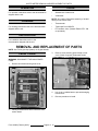
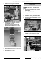
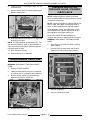
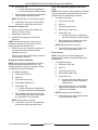
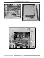
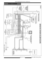
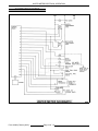
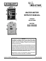
WATER METER
SERVICE MANUAL
HOBART
Model HWM
BAXTER
Model SP600-M1
Model SP600-M3
- NOTICE This Manual is prepared for the use of trained Hobart Service
Technicians and should not be used by those not properly
qualified. If you have attended a Hobart Service School for this
product, you may be qualified to perform all the procedures
described in this manual.
This manual is not intended to be all encompassing. If you have
not attended a Hobart Service School for this product, you should
read, in its entirety, the repair procedure you wish to perform to
determine if you have the necessary tools, instruments and skills
required to perform the procedure. Procedures for which you do
not have the necessary tools, instruments and skills should be
performed by a trained Hobart Service Technician.
Reproduction or other use of this Manual, without the express
written consent of Hobart Corporation, is prohibited.
A product of HOBART CORPORATION
TROY, OHIO 45374
Form 24692 (February 2001)
WATER METER GENERAL
TABLE OF CONTENTS
GENERAL . . . . . . . . . . . . . . . . . . . . . . . . . . . . . . . . . . . . . . . . . . . . . . . . . . . . . . . . . . . . . . . . . . . . . . . . . . . . .
Introduction . . . . . . . . . . . . . . . . . . . . . . . . . . . . . . . . . . . . . . . . . . . . . . . . . . . . . . . . . . . . . . . . . . . . . . . .
Features . . . . . . . . . . . . . . . . . . . . . . . . . . . . . . . . . . . . . . . . . . . . . . . . . . . . . . . . . . . . . . . . . . . . . . .
Delivery System . . . . . . . . . . . . . . . . . . . . . . . . . . . . . . . . . . . . . . . . . . . . . . . . . . . . . . . . . . . . . . . . .
Quantity Measuring System . . . . . . . . . . . . . . . . . . . . . . . . . . . . . . . . . . . . . . . . . . . . . . . . . . . . . . . .
Temperature Mixing System . . . . . . . . . . . . . . . . . . . . . . . . . . . . . . . . . . . . . . . . . . . . . . . . . . . . . . . .
Operation . . . . . . . . . . . . . . . . . . . . . . . . . . . . . . . . . . . . . . . . . . . . . . . . . . . . . . . . . . . . . . . . . . . . . . . . . .
Cleaning . . . . . . . . . . . . . . . . . . . . . . . . . . . . . . . . . . . . . . . . . . . . . . . . . . . . . . . . . . . . . . . . . . . . . . . . . .
Installation . . . . . . . . . . . . . . . . . . . . . . . . . . . . . . . . . . . . . . . . . . . . . . . . . . . . . . . . . . . . . . . . . . . . . . . . .
Tools . . . . . . . . . . . . . . . . . . . . . . . . . . . . . . . . . . . . . . . . . . . . . . . . . . . . . . . . . . . . . . . . . . . . . . . . . . . . .
3
3
3
3
3
3
4
4
4
4
REMOVAL AND REPLACEMENT OF PARTS . . . . . . . . . . . . . . . . . . . . . . . . . . . . . . . . . . . . . . . . . . . . . . . . .
Front Cover . . . . . . . . . . . . . . . . . . . . . . . . . . . . . . . . . . . . . . . . . . . . . . . . . . . . . . . . . . . . . . . . . . . . . . . .
Control Board . . . . . . . . . . . . . . . . . . . . . . . . . . . . . . . . . . . . . . . . . . . . . . . . . . . . . . . . . . . . . . . . . . . . . . .
Keypad Assembly . . . . . . . . . . . . . . . . . . . . . . . . . . . . . . . . . . . . . . . . . . . . . . . . . . . . . . . . . . . . . . . . . . .
Flow Meter . . . . . . . . . . . . . . . . . . . . . . . . . . . . . . . . . . . . . . . . . . . . . . . . . . . . . . . . . . . . . . . . . . . . . . . . .
Vacuum Breaker . . . . . . . . . . . . . . . . . . . . . . . . . . . . . . . . . . . . . . . . . . . . . . . . . . . . . . . . . . . . . . . . . . . .
Solenoid Valve . . . . . . . . . . . . . . . . . . . . . . . . . . . . . . . . . . . . . . . . . . . . . . . . . . . . . . . . . . . . . . . . . . . . . .
Mixer Valve / Gear Motor / Switches . . . . . . . . . . . . . . . . . . . . . . . . . . . . . . . . . . . . . . . . . . . . . . . . . . . . .
Transformers, Relay, Fan . . . . . . . . . . . . . . . . . . . . . . . . . . . . . . . . . . . . . . . . . . . . . . . . . . . . . . . . . . . . .
Pressure Regulator, Pressure Gauge, Strainer, Check Valve . . . . . . . . . . . . . . . . . . . . . . . . . . . . . . . . . . .
4
4
5
5
6
6
6
7
8
8
SERVICE PROCEDURES AND ADJUSTMENTS . . . . . . . . . . . . . . . . . . . . . . . . . . . . . . . . . . . . . . . . . . . . . . . 9
Solenoid Valve Coil Test . . . . . . . . . . . . . . . . . . . . . . . . . . . . . . . . . . . . . . . . . . . . . . . . . . . . . . . . . . . . . . 9
Thermistor Test . . . . . . . . . . . . . . . . . . . . . . . . . . . . . . . . . . . . . . . . . . . . . . . . . . . . . . . . . . . . . . . . . . . . . 9
Probe Test . . . . . . . . . . . . . . . . . . . . . . . . . . . . . . . . . . . . . . . . . . . . . . . . . . . . . . . . . . . . . . . . . . . . . . . . . 9
Gear Motor Test . . . . . . . . . . . . . . . . . . . . . . . . . . . . . . . . . . . . . . . . . . . . . . . . . . . . . . . . . . . . . . . . . . . . . 9
Fan Motor Test . . . . . . . . . . . . . . . . . . . . . . . . . . . . . . . . . . . . . . . . . . . . . . . . . . . . . . . . . . . . . . . . . . . . . 9
Calibration Procedure . . . . . . . . . . . . . . . . . . . . . . . . . . . . . . . . . . . . . . . . . . . . . . . . . . . . . . . . . . . . . . . . 9
Delivery Amount Calibration . . . . . . . . . . . . . . . . . . . . . . . . . . . . . . . . . . . . . . . . . . . . . . . . . . . . . . . . 9
Solenoid Correction Test . . . . . . . . . . . . . . . . . . . . . . . . . . . . . . . . . . . . . . . . . . . . . . . . . . . . . . . . . 10
Solenoid Correction Calibration . . . . . . . . . . . . . . . . . . . . . . . . . . . . . . . . . . . . . . . . . . . . . . . . . . . . 10
Flush Time Calibration (Applies to M-3 Units Only) . . . . . . . . . . . . . . . . . . . . . . . . . . . . . . . . . . . . . . 10
Units Lockout . . . . . . . . . . . . . . . . . . . . . . . . . . . . . . . . . . . . . . . . . . . . . . . . . . . . . . . . . . . . . . . . . . 10
ELECTRICAL OPERATION . . . . . . . . . . . . . . . . . . . . . . . . . . . . . . . . . . . . . . . . . . . . . . . . . . . . . . . . . . . . . .
Component Function . . . . . . . . . . . . . . . . . . . . . . . . . . . . . . . . . . . . . . . . . . . . . . . . . . . . . . . . . . . . . . . .
Component Location . . . . . . . . . . . . . . . . . . . . . . . . . . . . . . . . . . . . . . . . . . . . . . . . . . . . . . . . . . . . . . . .
Wiring Diagram . . . . . . . . . . . . . . . . . . . . . . . . . . . . . . . . . . . . . . . . . . . . . . . . . . . . . . . . . . . . . . . . . . . .
Schematic Diagram . . . . . . . . . . . . . . . . . . . . . . . . . . . . . . . . . . . . . . . . . . . . . . . . . . . . . . . . . . . . . . . . .
11
11
11
13
14
TROUBLESHOOTING . . . . . . . . . . . . . . . . . . . . . . . . . . . . . . . . . . . . . . . . . . . . . . . . . . . . . . . . . . . . . . . . . . 15
CONDENSED SPARE PARTS LIST . . . . . . . . . . . . . . . . . . . . . . . . . . . . . . . . . . . . . . . . . . . . . . . . . . . . . . . . 16
© HOBART CORPORATION 2001
Form 24692 (February 2001)
Page 2 of 16
WATER METER GENERAL
GENERAL
Delivery System
INTRODUCTION
All of the information, illustrations and specifications
contained in this manual are based on the latest
product information available at the time of printing.
The water meter will deliver a specific amount of
water at a specific temperature and is
microcomputer controlled. A chiller can be
connected to the meter and is controlled by a relay
located inside the meter. There are large digital
displays and a temperature probe which senses
flour, dough, or room temperature.
Features
•
Units of Measure: English ((F, Pounds/Ounces)
or Metric ((C, Liters/centiliters) may be
selected for water temperature and amount.
•
Set Temperature: Displays actual and set
temperatures. Adjustment light indicates when
meter is adjusting temperature due to new
setting or fluctuations in line temperature or
pressure. Temperature range is between 32(F
and 99(F, or 0( and 37(C.
•
Test Flow: Allows meter to adjust water
temperature before delivering to mixer.
•
Set Amount and Amount Delivered: Individually
displayed. Dispenses 5 - 1,000 pounds or 2 462 liters. Delivery can be interrupted, the
amount set changed (above the amount
already dispensed) and delivery resumed. The
total amount delivered is the last set amount
entered and displayed.
•
Start/Resume: Begins delivery cycle or
resumes cycle when interrupted.
•
Power Failure Safe Memory: Water meter
remembers last setting during blackout or
accidental disconnection from power.
Specifications
•
Input hot water = 140(F maximum, 30-100 psi,
1/2" pipe.
•
Input cold water = 32(F minimum, 30-100 psi,
1/2" pipe.
•
Requires 120V AC 60/1 outlet with ground fault
protection. Less than 1 amp draw.
•
Delivery accuracy: ± 1% @ 20 psi. inlet
pressure (above 6 lb. Delivery).
•
Temperature accuracy: ± 2(.
•
Temperature adjustment time: Normally less
than 30 seconds for any set temperature.
The meter has hot and cold water inputs. The inputs
have external pressure regulators and gauges
supplied to adjust the incoming flow pressures to 20
psi. Inside the meter the hot and cold water lines
join at the mixing valve and exit the mixing valve
from the mixer output line.
On standard meters (HWM, SP600-M1), this mixer
output line contains the internal water temperature
sensor, the flow meter and the solenoid shut off
valve. The water exits through a backflow preventer
and out through the delivery hose.
On chiller meters (SP600-M3), the mixer output line
branches out into two lines. One line is the same as
the standard meter. The other line is a bypass line
which has a separate shut off solenoid and can
recycle water to the chiller or can go to a drain. The
second line allows the water temperature to stabilize
without having to move the dispensing hose
between a sink and desired delivery location, which
is necessary with the standard meter.
On both standard and chiller meters there is a relay
supplied which when hooked up to the chiller will
turn on the pump whenever "Test Flow" or
"Delivery" is running.
Quantity Measuring System
The meter uses a positive displacement
paddlewheel style flow meter to measure the
amount of water flowing through the system. This
flow meter sends out a nominal 154 electrical pulses
per gallon that are read by the microprocessor.
Temperature Mixing System
The hot and cold water mixing system uses a threeway valve which is controlled by a 12VDC
gearmotor and two limit switches. The mixed water's
temperature is measured by the water thermistor.
This information is sent back to the control board
which compares this temperature with the set
temperature and turns the valve accordingly using
the gearmotor, thereby changing the water
temperature. This is done until the set water
temperature is achieved or until one of the limit
switches is reached.
Page 3 of 16
Form 24692 (February 2001)
WATER METER REMOVAL AND REPLACEMENT OF PARTS
OPERATION
TOOLS
For operation instructions refer to the documentation
shipped with the unit.
•
Standard set of hand tools.
•
VOM meter.
NOTE: Any quality VOM with a sensitivity of 20,000
ohms per volt can be used.
CLEANING
For cleaning instructions refer to the documentation
shipped with the unit.
•
Thermometer.
•
Teflon tape Part # 508473.
•
RTV sealant, clear. (General Electric RTV 108
or equivalent)
INSTALLATION
For installation instructions refer to the
documentation shipped with the unit.
REMOVAL AND REPLACEMENT OF PARTS
NOTE: Use Teflon pipe tape (sealer) on all pipe threads.
FRONT COVER
3.
Remove screw securing ground strap to front
cover. Watch for spacer underneath shield.
4.
Lay cover on padded area to prevent damaging
front surface.
5.
Reverse procedure to install.
WARNING: DISCONNECT THE MAIN POWER
CORD.
1.
2.
Remove six screws securing front cover.
Identify and disconnect three connectors from
control board.
Form 24692 (February 2001)
Page 4 of 16
WATER METER REMOVAL AND REPLACEMENT OF PARTS
CONTROL BOARD
4.
Remove standoffs securing control board and
lift board off.
5.
Reverse procedure to install.
WARNING: DISCONNECT THE MAIN POWER
CORD.
CAUTION: Certain components in this system
are subject to damage by electrostatic discharge
during field repairs. A field service grounding kit
is available to prevent damage. The field service
grounding kit must be used anytime the control
board is handled.
1.
Remove "FRONT COVER".
2.
Remove screws securing metal shield. Watch
for spacers on each screw underneath the
shield.
KEYPAD ASSEMBLY
WARNING: DISCONNECT THE MAIN POWER
CORD.
3.
Disconnect connector from keypad.
1.
Remove the "CONTROL BOARD".
2.
Remove nuts and flat washers securing keypad
assembly to front cover and lift assembly off.
NOTE: On reassembly, put RTV on top two studs to
insulate them from the back of the control board.
Page 5 of 16
Form 24692 (February 2001)
WATER METER REMOVAL AND REPLACEMENT OF PARTS
3.
Remove nuts and lockwashers securing keypad
to plate.
4.
Pull rubber strip off pins.
5.
Lift flow meter out of unit.
6.
Reverse procedure to install.
NOTE: Make sure flow sensor on top of flow meter
is finger tight.
VACUUM BREAKER
WARNING: DISCONNECT THE MAIN POWER
CORD.
5.
Separate keypad from mounting plate.
6.
Reverse procedure to install.
FLOW METER
NOTE: Any wire ties removed should be replaced
when service is complete.
1.
Shut off the hot and the cold water incoming
water supplies.
2.
Unscrew dispensing hose from outlet of
vacuum breaker.
3.
Unscrew vacuum breaker from welded fitting.
4.
Remove fitting from old vacuum breaker and
install on new one.
5.
Reverse procedure to install.
WARNING: DISCONNECT THE MAIN POWER
CORD.
SOLENOID VALVE
1.
Shut off the hot and the cold water incoming
water supplies.
2.
Remove "FRONT COVER".
3.
Identify and disconnect flow meter wires from
terminal strip.
4.
Unscrew fitting on both sides of flow meter.
Watch for fiber sealing washers.
WARNING: DISCONNECT THE MAIN POWER
CORD.
1.
Shut off the hot and the cold water incoming
water supplies.
2.
Remove "FRONT COVER".
3.
Identify and disconnect solenoid coil wires from
terminal strip.
NOTE: Keep wires twisted to reduce electrical
noise.
4.
Form 24692 (February 2001)
Page 6 of 16
Loosen hose clamp at top of solenoid valve.
WATER METER REMOVAL AND REPLACEMENT OF PARTS
5.
Unscrew fitting on right side of flow meter.
Watch for fiber sealing washer.
MIXER VALVE / GEAR MOTOR /
SWITCHES
WARNING: DISCONNECT THE MAIN POWER
CORD.
6.
Work solenoid valve fitting out of hose and lift
valve assembly out of unit.
7.
Remove cover from coil junction box and
disconnect wires. Install wires on new valve.
8.
Remove fittings from solenoid valve and install
on new valve.
9.
Reverse procedure to install.
1.
Shut off the hot and the cold water incoming
water supplies.
2.
Remove "FRONT COVER".
3.
Identify and disconnect motor wires from
terminal strip.
4.
Do steps 4, 5, and 6 in removing "SOLENOID
VALVE". Lay assembly in bottom of box.
5.
Unscrew left fitting on flow meter and lay meter
in bottom of box.
6.
Unscrew thermistor compression nut and pull
thermistor out of pipe. Let thermistor hang free
inside box or tuck it into the wiring harness.
7.
Identify and disconnect wires from switches.
Page 7 of 16
Form 24692 (February 2001)
WATER METER REMOVAL AND REPLACEMENT OF PARTS
8.
Unscrew fittings on incoming hot water line and
cold water line.
9.
Remove screws and nuts securing pipe support
plates to sides of box.
PRESSURE REGULATOR,
PRESSURE GAUGE, STRAINER,
CHECK VALVE
NOTE: Pressure regulator, strainer, and check
valve must be installed correctly with arrow on body
in direction of water flow.
NOTE: If pressure regulator is replaced, adjust new
one for 20psi. while water is flowing and mixing
valve is centered between hot and cold position.
Set temperature at 95(F and allow water to flow
until temperature is reached. Adjust both hot and
cold regulators until gauges read 20 psi.
Refer to the INSTRUCTIONS MANUAL for
complete instructions on setting the water pressure.
10. Work assembly out by sliding it to the right side
and lifting out of box.
NOTE: The right side plate is sealed with RTV. The
seal has to be broken in order to slide assembly to
right. Also note that left plate is welded to pipe and
right plate slides on pipe.
WARNING: DISCONNECT THE MAIN POWER
CORD.
1.
Shut off the hot and the cold water incoming
water supplies.
2.
Unscrew fitting at water meter and plumber
supplied union fitting (if one was installed).
3.
Replace component.
4.
Reverse procedure to install.
11. Work insulation off pipe.
12. Reverse procedure to assemble.
TRANSFORMERS, RELAY, FAN
WARNING: DISCONNECT THE MAIN POWER
CORD.
1.
Remove "FRONT COVER".
2.
Identify and disconnect wires from component
or terminal strip for component being replaced.
3.
Remove screws securing component being
replaced and remove component.
4.
Reverse procedure to install.
Form 24692 (February 2001)
Page 8 of 16
WATER METER SERVICE PROCEDURES AND ADJUSTMENTS
SERVICE PROCEDURES AND ADJUSTMENTS
SOLENOID VALVE COIL TEST
GEAR MOTOR TEST
1.
WARNING: DISCONNECT THE MAIN
POWER CORD.
1.
WARNING: DISCONNECT THE MAIN
POWER CORD.
2.
Remove "FRONT COVER".
2.
Remove "FRONT COVER".
3.
Identify and disconnect solenoid valve wires
from terminal strip.
3.
Identify and disconnect gear motor wires from
terminal strip.
4.
With ohm meter, check resistance between coil
wires. Reading should be approximately 100
ohms.
4.
With ohm meter, check resistance between
motor wires. Reading should be approximately
30 ohms.
THERMISTOR TEST
FAN MOTOR TEST
1.
WARNING: DISCONNECT THE MAIN
POWER CORD.
1.
WARNING: DISCONNECT THE MAIN
POWER CORD.
2.
Remove "FRONT COVER".
2.
Remove "FRONT COVER".
3.
Identify and disconnect thermistor wires from
terminal strip.
3.
Identify and disconnect fan motor wires from
terminal strip.
4.
With ohm meter, check resistance between
thermistor wires. Initial reading should be
approximately 12,000 ohms at room
temperature (70(F).
4.
With ohm meter, check resistance between
motor wires. Reading should be approximately
350 ohms.
NOTE: With meter connected, resistance may start
changing.
Test
PROBE TEST
1.
WARNING: DISCONNECT THE MAIN
POWER CORD.
2.
Disconnect probe connector.
3.
With ohm meter, check resistance between
pins on probe plug. Initial reading should be
approximately 12,000 ohms at room
temperature (70(F).
CALIBRATION PROCEDURE
1.
Deliver 20 pounds of water using an accurate
scale to measure.
2.
If error is less than 5%, calibrate delivery
amount.
NOTE: Calibration procedure can only be performed
on control boards that have a program chip version
22 or higher installed. If an earlier version chip is
installed, replace it with the latest version.
If error is more than 5%, replace flow meter.
NOTE: With meter connected, resistance may start
changing.
Delivery Amount Calibration
NOTE: This procedure adjusts the pulses per
volume rate for the flow meter. Any changes should
be made one increment at a time and checked after
each adjustment.
1.
Page 9 of 16
To change this setting:
A.
Press "Set Temp" key.
B.
Enter 32.
C.
Press "Set Amount" key.
D.
Enter 93303 (933lbs. 3oz.)
Form 24692 (February 2001)
WATER METER SERVICE PROCEDURES AND ADJUSTMENTS
E.
Press "Start" key.
1)
F.
Current stored value is displayed in
the water temperature setting window.
Enter desired value between 100 and 500
which represent pulses per gallon.
NOTE: Default value is 154 pulses per gallon.
Flush Time Calibration (applies to M-3 units
only)
NOTE: Flush is used on chiller meters to flush water
until the temperature has equilibrated. Flush time
required may vary depending on locations.
1.
To change this setting:
A.
Press "Set Temp" key.
B.
Enter 32.
Solenoid Correction Test
C.
Press "Set Amount" key.
1.
Deliver 1 pound of water and measure the
number of ounces of error.
D.
Enter 91101 (911lbs. 1oz.)
E.
Press "Start" key.
2.
Repeat step 1 three times.
3.
Calculate the average error of the three
deliveries.
G.
Press "Start" key to save new pulse rate
and return to normal operation mode.
1)
F.
NOTE: Unless the flow meter is grossly out of
calibration, this amount is the error due to the
closing speed of the solenoid valve.
4.
G.
If deliver error due to solenoid is less than 5
ounces, perform the solenoid correction
calibration to correct.
NOTE: This procedure compensates for the time
delay when the water solenoid shuts off. Any
changes should be made one increment at a time
and checked after each adjustment.
NOTE: This prevents or allows changing the
dispensing units between Celsius/Fahrenheit and
Pounds/Liters.
1.
To change this setting:
Press "Set Temp" key.
B.
Enter 32.
C.
Press "Set Amount" key.
D.
Enter 92202 (922lbs. 2oz.)
E.
Press "Start" key.
1)
F.
To change this setting:
A.
Press "Set Temp" key.
B.
Enter 32.
C.
Press "Set Amount" key.
D.
Enter 94404 (944lbs. 4oz.)
E.
Press "Start" key.
1)
F.
Current stored value is displayed in
the water temperature setting window.
Enter desired value between 0 and 200.
This represents flow meter pulses added
to compensate for the time delay.
NOTE: Default value is 4 pulses.
G.
Press "Start" key to save new pulse rate
and return to normal operation mode.
Form 24692 (February 2001)
Press "Start" key to save new time and
return to normal operation mode.
Units Lockout
Solenoid Correction Calibration
A.
Enter desired value between 0 and 120.
This represents time in seconds.
NOTE: Default value is 30 seconds.
If delivery error due to solenoid is more than 5
ounces, replace solenoid.
1.
Current stored value is displayed in
the water temperature setting window.
Page 10 of 16
Current stored value (000) or (001)is
displayed in the water temperature
setting window.
Enter desired value 0 or 1. Code (000)
means lockout disabled and code (001)
means lockout enabled.
NOTE: Default value is Disabled (0).
G.
Press "Start" key to save code and return
to normal operation mode.
WATER METER ELECTRICAL OPERATION
ELECTRICAL OPERATION
COMPONENT FUNCTION
CONTROL BOARD . . . . . . . . . . . . . . . .
Controls operation of water meter.
MIXER VALVE SWITCHES . . . . . . . . . .
Signals control board when mixer valve is in maximum hot or cold
water position.
GEAR MOTOR . . . . . . . . . . . . . . . . . . . .
Drives mixer valve according to signals received from control
board.
FAN MOTOR . . . . . . . . . . . . . . . . . . . . .
Rotates fan to circulate air within the box.
FLOW METER / SENSOR . . . . . . . . . . .
Monitors water flow and sends signals to control board. Meter is a
positive displacement paddlewheel style. This flow meter sends out
a nominal 154 electrical pulses per gallon that are read by the
microprocessor control.
THERMISTOR . . . . . . . . . . . . . . . . . . . .
Monitors water temperature inside mixer valve and sends signals to
control board.
TEMPERATURE PROBE . . . . . . . . . . . .
Measures temperature of product in mixer bowl.
SOLENOID VALVE . . . . . . . . . . . . . . . . .
Controlled by control board to dispense water.
COMPONENT LOCATION
Page 11 of 16
Form 24692 (February 2001)
WATER METER ELECTRICAL OPERATION
Form 24692 (February 2001)
Page 12 of 16
WATER METER ELECTRICAL OPERATION
WIRING DIAGRAM
Page 13 of 16
Form 24692 (February 2001)
WATER METER ELECTRICAL OPERATION
SCHEMATIC DIAGRAM
Form 24692 (February 2001)
Page 14 of 16
WATER METER TROUBLESHOOTING
TROUBLESHOOTING
SYMPTOM
Unit is plugged in but no displays lit.
1.
2.
3.
4.
POSSIBLE CAUSES
Tripped breaker.
Loose wire connections.
Transformer malfunction.
Control board malfunction.
Unit is plugged in, displays lit, but no response to
keypad input.
1. Control board memory corrupted. Unplug meter
for at least 8 hours to reset memory. (Memory is
backed up by a capacitor which will discharge
when meter is unplugged)
2. Loose keypad cable connection.
3. Keypad malfunction.
4. Control board malfunction.
Hand-held temperature display reads 32 at all times.
(Typically indicates open temperature sensor circuit)
1.
2.
3.
4.
Hand-held temperature display reads 99 at all times.
(Typically indicates shorted temperature sensor
circuit)
1. Probe malfunction.
2. Shorted internal wiring.
3. Control board malfunction.
Temperature of water delivered is out by more than
± 2(F. (Temperature is best measured by delivering
at least 20 pounds of water into a large plastic, not
metal, container after the meter temperature has
stabilized.)
1. Temperature fluctuates due to having other than
20 psi flow pressure at both inlets. (Pressure must
be checked with the meter set to an intermediate
temperature, not when "Full hot" or "Full cold"
lights on the meter are lit.)
2. Internal water temperature probe malfunction.
3. Control board malfunction.
Delivery amount is out by more than ± 1%. (Delivery
amount is best measured by delivering at least 20
pounds of water using an accurate scale to measure.)
1. Flow meter out of calibration. Calibrate as
outlined in Service Procedures and Adjustments
"CALIBRATION PROCEDURE".
Temperature won't adjust.
1. No water pressure (no flow) to both or one side
(hot or cold) of water meter inlet. Ensure proper
(20 psi) pressure to both hot and cold inlets.
2. Loose or bad wiring connections.
3. Water temperature sensor malfunction.
4. Mixer valve gearmotor malfunction.
5. Transformer malfunction.
6. Mixer valve limit switch malfunction.
7. Control board malfunction.
Temperature won't settle into set temperature, goes
above and below set point by more than 3 degrees.
1. Temperature fluctuates due to having other than
20 psi flow pressure at both inlets. (Pressure must
be checked with the meter set to an intermediate
temperature, not when "Full hot" or "Full cold"
lights on the meter are lit.)
2. Water supply temperatures fluctuating by large
amounts (hot water tank or chiller could have run
out of tempered water or be on long line runs,
etc.)
Loose hand-held probe plug connection.
Loose internal wiring.
Probe malfunction.
Control board malfunction.
Page 15 of 16
Form 24692 (February 2001)
WATER METER CONDENSED SPARE PARTS LIST
CONDENSED SPARE PARTS LIST
WATER METER
Part Number
Description
01-10J410-1
Cover, PC Board
01-10J348-1
Probe, Handheld
01-10J460-1
Meter, Flow
01-100V10-110
Transformer, 120V
01-10J429-1
Microswitch
01-10J422-101
Thermistor, Water
01-10J423-1
Valve, Solenoid
01-100V17-204
Gauge, Pressure
01-100V17-330
Regulator, Pressure
Form 24692 (February 2001)
Printed in U.S.A.