1
SPLIT-TYPE, HEAT PUMP AIR CONDITIONERS
November 2010
No. OCH487
TECHNICAL & SERVICE MANUAL
Indoor unit
[Model names]
[Service Ref.]
SLZ-KA09NA.TH
SLZ-KA12NA.TH
SLZ-KA15NA.TH
SLZ-KA09NA
SLZ-KA12NA
SLZ-KA15NA
Note:
• This manual describes only
service data of the indoor
units.
• RoHS compliant products
have <G> mark on the spec
name plate.
• For servicing RoHS compliant products, refer to the
RoHS Parts List.
CONTENTS
Model name
indication
1.
2.
3.
4.
5.
6.
7.
8.
9.
INDOOR UNIT
PART NAMES AND FUNCTIONS ....... 2
SPECIFICATIONS ............................... 5
OUTLINES AND DIMENSIONS........... 7
WIRING DIAGRAM .............................. 9
REFRIGERANT SYSTEM DIAGRAM ..... 10
TROUBLESHOOTING ....................... 11
SPECIAL FUNCTION ........................ 23
4-WAY AIR FLOW SYSTEM.............. 26
DISASSEMBLY PROCEDURE .......... 28
PARTS CATALOG (OCB487)
TEMP.
ON/OFF
REMOTE CONTROLLER
(Option)
9700058
1
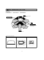
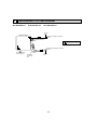
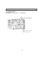
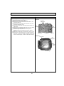
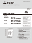
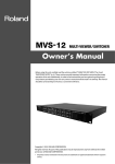
PART NAMES AND FUNCTIONS
Indoor Unit
SLZ-KA09NA.TH
SLZ-KA12NA.TH
SLZ-KA15NA.TH
Filter
Removes dust and pollutants
from inhaled air.
Horizontal Air Outlet
Sets horizontal airflow automatically
during cooling or dehumidifying.
Grille
Auto Air Swing Vane
Disperses airflow up and
down and adjusts the angle
of airflow direction.
Air Intake
Intakes air from room.
Remote controller (Optional parts)
Radio frequency interface
RF thermostat
Wired remote controller
TEMP.
2
ON/OFF
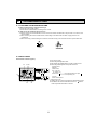
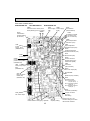
Wired remote controller (Option)
Once the controllers are set, the same operation mode can be repeated by simply pressing the ON/OFF button.
SLZ-KA09NA.TH
SLZ-KA12NA.TH
SLZ-KA15NA.TH
ON/OFF button
Temperature setting buttons
Down
Fan Speed button
Up
Timer Menu button
(Monitor/Set button)
Filter
button
(<Enter> button)
Mode button (Return button)
TEMP.
ON/OFF
Set Time buttons
Check button (Clear button)
Back
Ahead
Timer On/Off button
(Set Day button)
Test Run button
MENU
BACK
PAR-21MAA
MONITOR/SET
ON/OFF
FILTER
DAY
CLOCK
CHECK TEST
OPERATION
Airflow Up/Down button
CLEAR
Louver button
(
Operation button)
To return operation
number
Opening the
cover
Ventilation button
( Operation button)
Built-in temperature sensor
3
To go to next operation
number
Wired remote controller (Option)
Display Section
For purposes of this explanation,
all parts of the display are shown.
During actual operation, only
the relevant items will be lit.
Day-of-Week
“Sensor” indication
Shows the current day of the week.
Displays when the remote controller
sensor is used.
Time/Timer Display
Shows the current time, unless the simple or Auto Off
timer is set.
If the simple or Auto Off timer is set, the time to be
switched off is shown.
“Locked” indicator
Indicates that remote controller buttons have been locked.
Identifies the current operation
“Clean The Filter” indicator
Shows the operating mode, etc.
*Multilanguage display is available.
To be displayed on when it is time to
clean the filter.
TIME SUN MON TUE WED THU FRI SAT
TIMER
Hr
ON
AFTER
AFTER OFF
ERROR CODE
“Centrally Controlled” indicator
Indicates that operation from the
remote controller has been prohibited by a master controller.
FUNCTION
FILTER
°F°C
°F°C
WEEKLY
SIMPLE
AUTO OFF
ONLY1Hr.
Timer indicators
The indicator comes on if the corresponding timer is set.
Fan Speed indicator
Shows the selected fan speed.
“Timer is Off” indicator
Indicates that the timer is off.
Up/Down Air Direction indicator
Shows the direction of the
outcoming airflow.
“One Hour Only” indicator
Temperature Setting
Shows the target temperature.
Displays if the airflow is set to
low or downward during COOL
or DRY mode. (Operation varies
according to model.)
The indicator goes off in one hour,
when the airflow direction also
changes.
Room Temperature display
Shows the room temperature. The room
temperature display range is 46~102°F.
The display blinks if the temperature
is less than 46°F or 102°F or more.
Ventilation indicator
Appears when the unit is running in
Ventilation mode.
Louver display
Indicates the action of the swing louver.
Does not appear if the louver is not
running.
(Power On indicator)
Indicates that the power is on.
Note:
● “PLEASE WAIT” message
This message is displayed for approximately 3 minutes when power is supplied to the indoor unit or when the unit is recovering from a power failure.
● “NOT AVAILABLE” message
This message is displayed if an invalid button is pressed (to operate a function that the indoor unit does not have).
If a single remote controller is used to operate multiple indoor units simultaneously that are different types, this message will not be displayed as
far as any of the indoor units is equipped with the function.
4
2
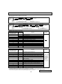
SPECIFICATIONS
Indoor model
SLZ-KA09NA
Power supply
V, phase, Hz
Max. fuse size (time delay)/Disconnect switch A
Min. circuit ampacity
A
Fan motor
F.L.A
Airflow
Dry
CFM
(Low - Med. - High)
Wet
CFM
Moisture removal
pt/h
Sound pressure level (Low - Med. - High)
dB(A)
External finish color
208/230, 1, 60
15
1.0
0.23
0.28
0.28
280-320-350
280-320-390
280-320-390
250-290-320
250-290-350
250-290-350
1.2
2.3
4.5
29-32-38
30-34-39
31-35-40
Unit: Galvanized sheets with gray heat insulation
Grille: ABS resin Munsell 6.4Y 8.9/0.4
22-7/16 <25-19/32>
22-7/16 <25-19/32>
8-3/16 <25/32>
36 <7>
1-1/4
12 - 24 VDC
Dimensions unit <Grille>
W
D
H
Weight unit <Grille>
Field drainpipe O.D.
Control voltage (by buit-in transformer)
in.
in.
in.
lb.
in.
SLZ-KA12NA
SLZ-KA15NA
NOTE : Test conditions are based on AHRI 210/240.
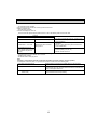
2-1. Operating range
(1) Power supply
Rated voltage
Guaranteed voltage (V)
208/230 V
1 phase
60 Hz
Indoor unit
Min. 187 208
230
Max. 253
(2) Operation
Intake air temperature (°F)
Mode
Cooling
Heating
Condition
Indoor
DB
80
95
67
Standard temperature
Maximum temperature
Minimum temperature
Maximum humidity
Standard temperature
Maximum temperature
Minimum temperature
Outdoor
WB
67
71
57
DB
95
115
14
60
67
60
47
75
-4
78%
70
80
70
WB
—
—
—
—
43
65
-5
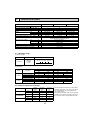
2-2. Outlet air speed and coverage
Model
SLZ-KA09NA
SLZ-KA12NA
SLZ-KA15NA
Function
Airflow
(CFM)
Air speed
(ft./s.)
Coverage
(ft.)
Dry
350
11.2
12.1
Wet
320
10.2
11.1
Dry
390
12.1
13.5
Wet
350
10.9
12.1
Dry
390
12.1
13.5
Wet
350
10.9
12.1
5
● The air coverage is the figure up to the position
where the air speed is 1 ft./s., when air is blown
out horizontally from the unit properly at the
High speed position.
The coverage should be used only as a general
guideline since it varies according to the size of
the room and furniture arraged inside the room.
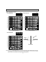
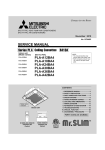
NOISE CRITERION CURVES
<60Hz>
SLZ-KA09NA.TH
NOTCH SPL(dB)
High
38
Medium
22
Low
29
LINE
OCTAVE BAND SOUND PRESSURE LEVEL, dB (0 dB = 0.0002 μbar)
OCTAVE BAND SOUND PRESSURE LEVEL, dB (0 dB = 0.0002 μbar)
80
70
NC-70
60
NC-60
50
NC-50
40
NC-40
30
NC-30
10
NOTCH SPL(dB)
High
39
Medium
40
Low
30
LINE
90
90
20
<60Hz>
SLZ-KA12NA.TH
APPROXIMATE
THRESHOLD OF
HEARING FOR
CONTINUOUS
NOISE
NC-20
80
70
60
NC-60
50
NC-50
40
NC-40
30
NC-30
20
10
63
125
250
500
1000
2000
4000
8000
NC-70
APPROXIMATE
THRESHOLD OF
HEARING FOR
CONTINUOUS
NOISE
63
125
NC-20
250
500
1000
2000
4000
8000
BAND CENTER FREQUENCIES, Hz
BAND CENTER FREQUENCIES, Hz
<60Hz>
SLZ-KA15NA.TH
NOTCH SPL(dB)
High
40
Medium
35
Low
31
LINE
OCTAVE BAND SOUND PRESSURE LEVEL, dB (0 dB = 0.0002 μbar)
90
UNIT
80
CEILING
70
NC-70
60
NC-60
5 ft
50
NC-50
40
MICROPHONE
NC-40
30
NC-30
20
10
APPROXIMATE
THRESHOLD OF
HEARING FOR
CONTINUOUS
NOISE
63
125
NC-20
250
500
1000
2000
4000
8000
BAND CENTER FREQUENCIES, Hz
NOTE: The sound level is measured in an anechoic room where echoes are few, when compressor stops. The sound
may be bigger than the indicated level in actual use due to surrounding echoes. The sound level can be higher
by about 2 dB than the indicated level during cooling and heating operation.
6
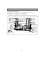
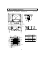
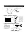
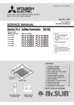
3
OUTLINES AND DIMENSIONS
22-7/16(570)
13-3/16(335)
1-7/32(31)
22-7/16(570)
:2-7/8(:73.4)
Cut out hole
12
0
Ceiling hole
16-17/32(420)
Suspension bolt pitch
22-11/16~24-13/32(576~620)
Ceiling surface
3-7/16(87)
2-7/32(56)
2-1/14(57)
19/32~1-15/32(15~37)
Suspension bolt pitch
7-27/32(199)
13-27/32(352)
13-3/16(335)
Refrigerant 21/32(17)
pipe (gas)
19/32~1-15/32(15~37)
22-11/16~24-13/32(576~620) Ceiling hole
7-15/16(202)
Drain pipe
VP-25 connection
(O.D.:1-1/4(:32))
Suspension bolt M10 or W3/8
9-1/16(230)
Ceiling surface
7-5/32(182)
8-3/16(208)
9-1/4(235)
1-7/8(48)
Grille
Wiring entry
1-1/16
Terminal block
+3/16 (27 +5)
0
0
25/32(20)
1-1/2~2-9/32(38~58)
Suspension bolt
lower edge
3-21/32(93)
7-19/32(193)
Refrigerant
pipe (liquid)
1-3/8(35)
25-19/32(650)
11-27/32(301)
Air outlet hole
Refrigerent pipe
(liquid)
Refrigerent pipe
(gas)
SLZ-KA09NA
1/4 inch
(W 6.35mm)
flared connection
3/8 inch
(W 9.52mm)
flared connection
SLZ-KA12NA
1/4 inch
(W 6.35mm)
flared connection
3/8 inch
(W 9.52mm)
flared connection
SLZ-KA15NA
1/4 inch
(W 6.35mm)
flared connection
1/2 inch
(W 12.7mm)
flared connection
Models
Brand label
2-5/32(55)
Grille
V/M
Drain hole
V/M
Auto vane
14-27/32(377)
Air intake hole
11-27/32(301)
Air outlet hole
25-19/32(650)
1(25)
3-:1/8(:2.8)
Burring hole
20-7/8(530)
V/M
V/M
Air intake grille
Vane motor
14-27/32(377)
Air intake hole
1-3/8(35)
Unit : inch (mm)
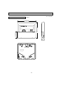
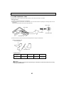
Detail drawing of fresh air intake
:3-15/16(:100)
120
2-19/32(66)
SLZ-KA15NA.TH
Fresh air
intake
19/32~1-15/32(15~37)
4-3/4(121)
SLZ-KA12NA.TH
4-21/32(118)
19/32~1-15/32(15~37)
SLZ-KA09NA.TH
2-5/32(55)
7
WIRED REMOTE CONTROLLER
Unit : inch (mm)
(Option)
1-23/32 (43.5)
4-23/32 (120)
5-1/8 (130)
3/4 (19)
8
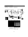
4
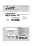
WIRING DIAGRAM
SLZ-KA09NA.TH
SLZ-KA12NA.TH
SLZ-KA15NA.TH
TB4
S1
S2
S3
GRILLE
MF
7
6
3
2
1
1
3
ORN
C1
P.B
RED
5
1 3 5 7 9
1
WHT
(FAN)
FAN
3
RED
1
(D·HEATER)
CNC
3 BLU 1
(D·U·M)
CNP
X1
ORN
BLU
5
20
RED
ORN
YLW
WHT
BLU
RED
BLU
MV
5
TO
OUTDOOR
UNIT
M
1~
M
1~
RED
WHT
MV
5
DP
YLW
YLW
MV
10
5
RED
RED
MV
RED
RED
BLK
YLW
BRN
WHT
BLU
H2
3 ORN
(POWER)
CND
3 RED
1
(POWER
BOARD)
CNDK
FUSE
1
I.B
1
3
BLU
(CONTROL)
CN3C
3
DC13.1V
1
X7
X6 X5 X4
WHT
(POWER
BOARD)
CN2D
SWE
ON
OFF
LED3
12345
CN32
<Fig: + 1>
MODELS
1
SW2
SLZKA09NA
ON
OFF
SLZKA12NA
ON
OFF
SLZKA15NA
ON
OFF
See Fig:+ 1
12345
3
CN24
2
2
1
CN51
5
RED
CN105
1
5
1
CN41
1 4
GRN
(VANE)
CN6V
6
1
1
5
WHT
(DRAIN)
CN31
CN90
9
3
1
BLK
RED
(2 PHASE) (INTAKE)
CN29
CN20
2
1 2
1
1
t°
2
t°
DS
t°
TH5
TH1
1
TH2
SYMBOL
C1
DP
DS
RFI
NAME
CAPACITOR (FAN MOTOR)
DRAIN PUMP
DRAIN SENSOR
RADIO FREQUENCY INTERFACE FOR
RF THERMOSTAT
H2
DEW PREVENTION HEATER
FAN MOTOR (WITH THERMAL FUSE)
MF
VANE MOTOR
MV
TB4
TERMINAL BLOCK
(INDOOR/OUTDOOR CONNECTING LINE)
TB15
TERMINAL BLOCK (REMOTE CONTROLLER
TRANSMISSION LINE)
TH1
ROOM TEMP. THERMISTOR
(32°F / 15kΩ, 77°F / 5.4kΩ DETECT)
TH2
PIPE TEMP. THERMISTOR/LIQUID
(32°F / 15kΩ, 77°F / 5.4kΩ DETECT)
TH5
COND. / EVA. TEMP. THERMISTOR
(32°F / 15kΩ, 77°F / 5.4kΩ DETECT)
OPTION PART
WIRED REMOTE CONTROLLER BOARD
R.B
TERMINAL BLOCK (REMOTE CONTROLLER
TB6
TRANSMISSION LINE)
NOTES: 1. Since the outdoor side electric wiring may change be sure to check the
outdoor unit electric wiring for servicing.
2. Indoor and outdoor connecting wires are made with poIarities, make wiring
matching terminal numbers (S1, S2, S3).
3. Use copper supply wires.
: Connector,
: Terminal (block).
4. SymboIs used in wiring diagram above are,
+For details on how to operate self-diagnosis refer to the technical manuals etc.
9
2
LED1
2
t°
[LEGEND]
NAME
INDOOR POWER BOARD
INDOOR CONTROLLER BOARD
CONNECTOR (LOSSNAY)
CONNECTOR (BACK-UP HEATING)
CONNECTOR (LLC)
CONNECTOR (REMOTE SWITCH)
CONNECTOR (HA TERMINAL-A)
CENTRALLY CONTROL
CONNECTOR (RADIO FREQUENCY INTERFACE)
FUSE (T6.3AL250V)
POWER SUPPLY (I.B)
POWER SUPPLY (I.B)
TRANSMISSION (INDOOR-OUTDOOR)
SWITCH (CAPACITY CODE)
SWITCH (EMERGENCY OPERATION)
DRAIN PUMP/DEW PREVENTION HEATER
RELAY (FAN MOTOR LL)
RELAY (FAN MOTOR Lo)
RELAY (FAN MOTOR Hi)
RELAY (FAN MOTOR Me)
BLK
WHT
3
1
BLU
WHT
(LIQUID) (REMOCON)
CN22
CN21
12345
The black square (■) indicates a switch position.
SYMBOL
P.B
I.B
CN2L
CN24
CN30
CN32
CN41
CN51
CN105
FUSE
LED1
LED2
LED3
SW2
SWE
X1
X4
X5
X6
X7
CN2S
(WHT)
CN30
5
RFI
12345
LED2
1
2
1
BLU
BLU
ON
OFF
CN2L
RED
ORN
YLW
WHT
BLU
SW2
CNSK
(RED)
2
TB15
1
2
R.B
TB6
1
2
5
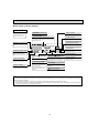
REFRIGERANT SYSTEM DIAGRAM
SLZ-KA09NA.TH
SLZ-KA12NA.TH
SLZ-KA15NA.TH
Strainer
#50
Heat exchanger
Refrigerant GAS pipe connection
(Flare)
Condenser/evaporator
temperature thermistor
(TH5)
Refrigerant flow in cooling
Refrigerant flow in heating
Refrigerant LIQUID pipe connection
(Flare)
Pipe temperature
thermistor/liquid
(TH2)
Room temperature
thermistor (TH1)
Distributor
with strainer
#50
Strainer
#50
10
6
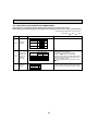
TROUBLESHOOTING
6-1. CAUTIONS ON TROUBLESHOOTING
(1) Before troubleshooting, check the followings:
1Check the power supply voltage.
2Check that the indoor/outdoor connecting wire is correct.
(2) Take care of the followings during servicing.
1 Before servicing the air conditioner, be sure to turn off the remote controller first to stop the main unit, and then turn
off the breaker.
2 When removing the indoor controller board, hold the edge of the board with care NOT to apply stress on the
components.
3 When connecting or disconnecting the connectors, hold the housing of the connector. DO NOT pull the lead wires.
Lead wire
6-2. SELF-CHECK
Wired remote controller (Option)
Turn on the power.
Press the [CHECK] button twice.
Set address with [TEMP] button if system control is used.
Press the [ON/OFF] button to stop the self-check.
CHECK button
Address
TEMP. button
IC : Indoor unit
OC: Outdoor unit
– – – – : No trouble generated in the past.
Check code
F F F F : No corresponding unit.
Unit No.
ERROR CODE
ERROR CODE
TEMP.
ON/OFF
MENU
BACK
PAR-21MAA
MONITOR/SET
ON/OFF
FILTER
DAY
CHECK TEST
OPERATION
CLOCK
ERROR CODE
Timer ON/OFF button
CLEAR
<To delete check code>
Display the error code on the self-check result display screen.
The address for self-check will blink when the ON/OFF
button is pressed twice within 3 seconds.
11
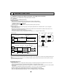
• Refer to the following tables for details on the check codes.
[Output pattern A]
Beeper sounds
OPERATION
INDICATOR
lamp blink
pattern
Beep
Beep Beep Beep
Off
Beep
1st
2 nd
3 rd
nth
On
On
On
On
Beep Beep
1st
Off
2 nd · · · Repeated
On
On
0.5 sec. Approx. 2.5 sec. 0.5 sec. 0.5 sec.
Self-check Approx. 2.5 sec. 0.5 sec. 0.5 sec. 0.5 sec.
starts
(Start signal
Number of blinks/beeps in pattern indicates the check
Number of blinks/beeps in pattern indicates
received)
code in the following table (i.e., n=5 for “P5”)
the check code in the following table
[Output pattern B]
Beeper sounds
OPERATION
INDICATOR
lamp blink
pattern
Beep
Beep Beep Beep
1st
Off
On
Approx. 3 sec.
Self-check Approx. 2.5 sec.
starts
(Start signal
received)
2nd
3 rd
On
On
On
0.5 sec. 0.5 sec. 0.5 sec.
Beep
Beep
nth
1st
On
Off
0.5 sec. Approx. 2.5 sec.
Number of blinks/beeps in pattern indicates the check
code in the following table (i.e., n=5 for “U2”)
On
Approx. 3 sec.
Beep
2 nd · · · Repeated
On
On
0.5 sec. 0.5 sec.
Number of blinks/beeps in pattern indicates
the check code in the following table
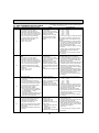
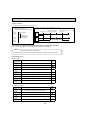
[Output pattern A] Errors detected by indoor unit
IR wireless remote controller Wired remote controller
Beeper sounds/OPERATION
INDICATOR lamp blinks
Check code
(Number of times)
1
P1
P2
2
P9
3
E6,E7
4
P4
5
P5
6
P6
7
EE
8
P8
9
E4, E5
–
10
–
11
12
Fb
E0, E3
–
–
E1, E2
Symptom
Remark
Intake sensor error
Pipe (TH2) sensor error
Pipe (TH5) sensor error
Indoor/outdoor unit communication error
Drain sensor error
Drain pump error
Freezing/Overheating protection operation
Communication error between indoor and outdoor units
Pipe temperature error
Remote controller signal receiving error
–
–
Indoor unit control system error (memory error, etc.)
Remote controller transmission error
Remote controller control board error
[Output pattern B] Errors detected by unit other than indoor unit (outdoor unit, etc.)
IR wireless remote controller Wired remote controller
Beeper sounds/OPERATION
INDICATOR lamp blinks
Check code
(Number of times)
1
E9
2
3
4
UP
U3,U4
UF
5
U2
6
U1,Ud
7
8
9
10
U5
U8
U6
U7
11
U9,UH
Symptom
Remark
Indoor/outdoor unit communication error
(Transmitting error) (Outdoor unit)
Compressor overcurrent interruption
Open/short of outdoor unit thermistors
Compressor overcurrent interruption (When compressor locked)
Abnormal high discharging temperature/49C operated/
insufficient refrigerant
Abnormal high pressure (63H operated)/Overheating
protection operation
Abnormal temperature of heatsink
Outdoor unit fan protection stop
Compressor overcurrent interruption/Abnormal of power module
Abnormality of superheat due to low discharge temperature
Abnormality such as overvoltage or voltage shortage and
abnormal synchronous signal to main circuit/Current sensor error
–
–
Other errors (Refer to the technical manual for the outdoor unit.)
For details, check
the LED display
of the outdoor
controller board.
As for outdoor
unit, refer to
outdoor unit’s
service manual.
–
12
–
13
Others
14
*1 If the beeper does not sound again after the initial 2 beeps to confirm the self-check start signal was received and
the OPERATION INDICATOR lamp does not come on, there are no error records.
*2 If the beeper sounds 3 times continuously “beep, beep, beep (0.4 + 0.4 + 0.4 sec.)” after the initial 2 beeps to confirm
the self-check start signal was received, the specified refrigerant address is incorrect.
continued to the next page.
12
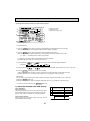
• On IR wireless remote controller
The continuous buzzer sounds from receiving section of indoor unit.
Blink of operation lamp
• On wired remote controller
Check code displayed on the LCD.
• If the unit cannot be operated properly after the test run, refer to the following table to find out the cause.
Symptom
Wired remote controller
Cause
PLEASE WAIT
For about 2 minutes after power-on
PLEASE WAIT → Error code
Subsequent to about 2 minutes
after power-on
No messages appear even
when operation switch is turned
ON (operation lamp does not
light up).
•For about 2 minutes after power-on, operation of the
remote controller is not possible due to system start-up.
(Correct operation)
•Connector for the outdoor unit’s protection device is not
connected.
•Reverse or open phase wiring for the outdoor unit’s
power terminal block
•Incorrect wiring between indoor and outdoor units.
(incorrect polarity of S1, S2, S3)
•Remote controller wire short
On the IR wireless remote controller with condition above, following phenomena take place.
• No signals from the remote controller can be received.
• Operation lamp is blinking.
• The buzzer makes a short ping sound.
Note:
Operation is not possible for about 30 seconds after cancellation of function selection. (Correct operation)
For description of each LED (LED1, 2, 3) provided on the indoor controller, refer to the following table.
LED2 (power for wired remote controller)
Indicates whether control power is supplied. Make sure that this LED is
always lit.
Indicates whether power is supplied to the wired remote controller.
This LED lights only in the case of the indoor unit which is connected to the
outdoor unit refrigerant address “0”.
LED3 (communication between indoor and
outdoor units)
Indicates state of communication between the indoor and outdoor units.
Make sure that this LED is always blinking.
LED1 (power for microprocessor)
13
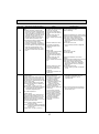
6-3. SELF-DIAGNOSIS ACTION TABLE
Error Code
P1
P2
P4
P5
Note: Refer to the manual of outdoor unit for the details of display
such as F, U, and other E.
Abnormal point and detection method
Room temperature thermistor (TH1)
1 The unit is in 3-minute resume
prevention mode if short/open of
thermistor is detected. Abnormal if the
unit does not reset normally after 3 minutes. (The unit returns to normal operation, if it has been reset normally.)
2 Constantly detected during cooling,
drying and heating operation
Short: 194°F or more
Open: -40°F or less
Cause
1 Defective thermistor
characteristics
2 Contact failure of connector
(CN20) on the indoor controller
board (Insert failure)
3 Breaking of wire or contact
failure of thermistor wiring
4 Defective indoor controller
board
Countermeasure
1–3 Check resistance value of thermistor.
30°F.....15.8k"
50°F.......9.6k"
70°F.......6.0k"
90°F.......3.9k"
100°F.......3.2k"
If you put force on (draw or bend) the lead wire
with measuring resistance value of thermistor, breaking of wire or contact failure can be
detected.
2 Check contact failure of connector (CN20)
on the indoor controller board. Refer to 6-4.
Turn the power back on and check restart
after inserting connector again.
4 Check room temperature display on remote
controller.
Replace indoor controller board if there is
abnormal difference with actual room
temperature.
Turn the power off, and on again to operate
after checking.
Pipe temperature thermistor/Liquid
(TH2)
1 The unit is in 3-minute resume
prevention mode if short/open of
thermistor is detected. Abnormal if the
unit does not reset normally after 3 minutes. (The unit returns to normal operation, if it has been reset normally.)
2 Constantly detected during cooling,
drying, and heating (except defrosting)
operation.
Short: 194°F or more
Open: -40°F or less
1 Defective thermistor
characteristics
2 Contact failure of connector
(CN21) on the indoor controller
board (Insert failure)
3 Breaking of wire or contact
failure of thermistor wiring
4 Defective refrigerant circuit is
causing thermistor temperature
of 194°F or more or -40°F or
less.
5 Defective indoor controller board
1–3 Check resistance value of thermistor.
For characteristics, refer to (P1) above.
2 Check contact failure of connector (CN21)
on the indoor controller board. Refer to 6-4.
Turn the power on and check restart after
inserting connector again.
4 Check pipe <liquid> temperature with remote
controller in test run mode. If pipe <liquid>
temperature is extremely low (in cooling
mode) or high (in heating mode), refrigerant
circuit may have defect.
5 Check pipe <liquid> temperature with remote
controller in test run mode. If there is extreme
difference with actual pipe <liquid> temperature, replace indoor controller board.
Turn the power off, and on again to operate
after checking.
Drain sensor (DS)
1 Suspensive abnormality, if short/open
of thermistor is detected for 30 seconds
continuously.
Turn off compressor and indoor fan.
2 Short/open is detected for 30 seconds continuously during suspensive abnormality.
(The unit returns to normal operation,
if it has been reset normally.)
3 Detect the following condition.
• During cooling and drying operation
• In case that pipe <liquid> temperature room temperature < -18 deg
(Except defrosting)
• When pipe <liquid> temperature or room
temperature is short/open temperature.
• During drain pump operation
1–3 Check resistance value of thermistor.
1 Defective thermistor
30°F.......6.3k"
characteristics
50°F.......3.9k"
2 Contact failure of connector
70°F.......2.5k"
(CN31) on the indoor controller
90°F.......1.6k"
board (Insert failure)
100°F.......1.3k"
3 Breaking of wire or contact
failure of drain sensor wiring
2 Check contact failure of connector (CN31)
on the indoor controller board. Refer to 6-4.
4 Defective indoor controller board
Turn the power back on and check restart
after inserting connector again.
4 Replace indoor controller board if drain
pump operates with the line of drain sensor
connector CN31-1 and 2 is short-circuited,
and abnormality reappears.
Turn the power off, and on again to operate
after checking.
Malfunction of drain pump (DP)
1 Suspensive abnormality, if thermistor
of drain sensor heats itself and
temperature rises slightly. Turn off
compressor and indoor fan.
2 Drain pomp is abnormal if the condition
above is detected during suspensive
abnormality.
3 Constantly detected during drain pump
operation
1 Malfunction of drain pump
2 Defective drain
Clogged drain pump
Clogged drain pipe
3 Attached drop of water at the
drain sensor
• Drops of drain trickles from
lead wire
• Clogged filter is causing
wave of drain.
4 Defective indoor controller board
14
1 Check if drain pump works.
2 Check drain function.
3 Check the setting of lead wire of drain sensor and check clogs of the filter.
4 Replace indoor controller board if drain
pump operates with the line of drain sensor
connector CN31-1 and 2 is short-circuited
and abnormality reappears.
Refer to 6-4.
Turn the power off, and on again to operate
after checking.
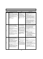
Error Code
P6
Abnormal point and detection method
Freezing/overheating protection is operating
1 Freezing protection (Cooling mode)
The unit is in 6-minute resume prevention
mode if pipe <liquid or condenser/evaporator> temperature stays under 5°F for
3 minutes after the compressor started.
Abnormal if it stays under 5°F for 3
minutes again within 16 minutes after
6-minute resume prevention mode.
Cause
(Cooling or drying mode)
1 Clogged filter (reduced airflow)
2 Short cycle of air path
3 Low-load (low temperature)
operation out of the tolerance
range
4 Defective indoor fan motor
• Fan motor is defective.
• Indoor controller board is defective.
2 Overheating protection (Heating mode)
The units is in 6-minute resume
prevention mode if pipe <condenser /
evaporator> temperature is detected as
over 158°F after the compressor started.
Abnormal if the temperature of over
158°F is detected again within 10 minutes after 6-minute resume prevention
mode.
5 Defective outdoor fan control
6 Overcharge of refrigerant
7 Defective refrigerant circuit
(clogging)
(Heating mode)
1 Clogged filter (reduced airflow)
2 Short cycle of air path
3 Overload (high temperature)
operation out of the tolerance
range
4 Defective indoor fan motor
• Fan motor is defective.
• Indoor controller board is defective.
5 Defective outdoor fan control
6 Overcharge of refrigerant
7 Defective refrigerant circuit
(clogging)
8 Bypass circuit of outdoor unit
is defective.
P8
Pipe temperature
1 Slight temperature difference
<Cooling mode>
between indoor room
Detected as abnormal when the pipe temtemperature and pipe <liquid
perature is not in the cooling range 3 minor condenser / evaporator>
utes after compressor start and 6 minutes
temperature thermistor
after the liquid or condenser/evaporator pipe
• Shortage of refrigerant
is out of cooling range.
• Disconnected holder of pipe
Note 1) It takes at least 9 min. to detect.
<liquid or condenser /
Note 2) Abnormality P8 is not detected in
evaporator> thermistor
drying mode.
• Defective refrigerant circuit
Cooling range : -5.4 deg ] (TH-TH1)
2 Converse connection of
TH: Lower temperature between liquid pipe
extension pipe (on plural units
temperature (TH2) and condenser/
connection)
evaporator temperature (TH5)
3 Converse wiring of indoor/
TH1: Intake temperature
outdoor unit connecting wire
(on plural units connection)
<Heating mode>
4 Defective detection of indoor
When 10 seconds have passed after the
room temperature and pipe
compressor starts operation and the hot
<condenser / evaporator>
adjustment mode has finished, the unit is
temperature thermistor
detected as abnormal when condenser/
5 Stop valve is not opened
evaporator pipe temperature is not in heatcompletely.
ing range within 20 minutes.
Note 3) It takes at least 27 minutes to
detect abnormality.
Note 4) It excludes the period of defrosting
(Detection restarts when defrosting
mode is over)
Heating range : 5.4 deg [ (TH5-TH1)
15
Countermeasure
(Cooling or drying mode)
1 Check clogging of the filter.
2 Remove blockage.
4 Measure the resistance of fan motor's winding.
Measure the output voltage of fan's connector
(FAN) on the indoor controller board.
WThe indoor controller board should be
normal when voltage of AC 208/230V is
detected while fan motor is connected.
Refer to 6-4.
5 Check outdoor fan motor.
67 Check operating condition of refrigerant
circuit.
(Heating mode)
1 Check clogs of the filter.
2 Remove blockage.
4 Measure the resistance of fan motor's
winding.
Measure the output voltage of fan's connector
(FAN) on the indoor controller board.
WThe indoor controller board should be
normal when voltage of AC 208/230V is
detected while fan motor is connected.
Refer to 6-4.
5 Check outdoor fan motor.
6~8Check operating condition of refrigerant
circuit.
1~4Check pipe <liquid or condenser /
evaporator> temperature with room
temperature display on remote
controller board.
23Check converse connection of extension
pipe or converse wiring of indoor/outdoor
unit connecting wire.
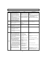
Error Code
P9
E0
or
E4
E3
or
E5
Abnormal point and detection method
Pipe temperature thermistor / Condenser
/ Evaporator (TH5)
1 The unit is in 3-minute resume protection mode if short/open of thermistor is
detected. Abnormal if the unit does not
get back to normal within 3 minutes. (The
unit returns to normal operation, if it has
been reset normally.)
2 Constantly detected during cooling,
drying, and heating operation (except
defrosting)
Short: 194°F or more
Open: -40°F or less
Countermeasure
Cause
1 Defective thermistor
1–3 Check resistance value of thermistor.
characteristics
For characteristics, refer to (P1) above.
2 Contact failure of connector
2 Check contact failure of connector (CN29)
(CN29) on the indoor controller
on the indoor controller board.
board (Insert failure)
Refer to 6-4.
3 Breaking of wire or contact
Turn the power on and check restart after
failure of thermistor wiring
inserting connector again.
4 Temperature of thermistor is
4 Operate in test run mode and check pipe
194°F or more or -40°F or less
<condenser/evaporator> temperature with
outdoor controller circuit board. If pipe
caused by defective refrigerant
<condenser/evaporator> temperature is
circuit.
extremely low (in cooling mode) or high (in
5 Defective indoor controller
heating mode), refrigerant circuit may have
board
defect.
5 Operate in test run mode and check pipe
<condenser/evaporator> temperature with
outdoor control circuit board. If there is
extreme difference with actual pipe
<condenser/evaporator> temperature replace
indoor controller board.
There is no abnormality if none of above
comes within the unit.
Turn the power off and on again to operate.
Remote controller transmission
error(E0)/signal receiving error(E4)
1 Abnormal if main or sub remote controller cannot receive any transmission
normally from indoor unit of refrigerant
address “0” for 3 minutes.
(Error code : E0)
2 Abnormal if sub-remote controller could
not receive for any signal for 2 minutes.
(Error code: E0)
1 Contact failure at transmission
wire of remote controller
2 All remote controllers are set
as “sub” remote controller. In
this case, E0 is displayed on
remote controller, and E4 is
displayed at LED (LED1, LED2)
on the outdoor controller circuit
board.
3 Miswiring of remote controller
4 Defective transmitting/receiving
circuit of remote controller
5 Defective transmitting/receiving
circuit of indoor controller board
of refrigerant address “0”
6 Noise has entered into the
transmission wire of remote
controller.
1 Abnormal if indoor controller board
cannot receive normally any data from
remote controller board or from other
indoor controller board for 3 minutes.
(Error code: E4)
2 Indoor controller board cannot receive
any signal from remote controller for 2
minutes. (Error code: E4)
Remote controller transmission
error(E3)/signal receiving error(E5)
1 Abnormal if remote controller could not
find blank of transmission path for 6 seconds and could not transmit.
(Error code: E3)
2 Remote controller receives transmitted
data at the same time, compares the
data, and when detecting it, judges
different data to be abnormal 30
continuous times. (Error code: E3)
1 2 remote controllers are set as
“main.”
(In case of 2 remote controllers)
2 Remote controller is connected
with 2 indoor units or more.
3 Repetition of refrigerant
address
4 Defective transmitting/receiving
circuit of remote controller
1 Abnormal if indoor controller board could 5 Defective transmitting/receiving
circuit of indoor controller board
not find blank of transmission path.
6 Noise has entered into trans(Error code: E5)
mission wire of remote control2 Indoor controller board receives transler.
mitted data at the same time, compares
the data,and when detecting it, judges
different data to be abnormal 30
continuous times. (Error code: E5)
16
1 Check disconnection or looseness of indoor
unit or transmission wire of remote controller.
2 Set one of the remote controllers “main”,
if there is no problem with the action above.
3 Check wiring of remote controller.
• Total wiring length: max. 500m
(Do not use cablex 3 or more)
• The number of connecting indoor units:
max. 16 units
• The number of connecting remote controller: max. 2 units
When the above-mentioned problem of 1~3
are not seen.
4 Diagnose remote controllers.
a) When “RC OK” is displayed,
remote controllers have no problem.
Turn the power off, and on again to check.
If abnormality generates again, replace
indoor controller board.
b) When “RC NG” is displayed,
replace remote controller.
c) When “RC E3”or “ERC 00-66” is displayed, noise may be causing abnormality.
1 Set a remote controller to main, and the
other to sub.
2 Remote controller is connected with only one
indoor unit.
3 The address changes to a separate setting.
4~6 Diagnose remote controller.
a) When “RC OK”is displayed, remote controllers have no problem.
Turn the power off, and on again to check.
When becoming abnormal again, replace
indoor controller board.
b) When “RC NG” is displayed, replace
remote controller.
c) When “RC E3”or “ERC 00-66” is displayed, noise may be causing abnormality.
Countermeasure
Error Code
Abnormal point and detection method
E6
Indoor/outdoor unit communication
error (Signal receiving error)
1 Abnormal if indoor controller board
cannot receive any signal normally for 6
minutes after turning the power on.
2 Abnormal if indoor controller board
cannot receive any signal normally for 3
minutes.
3 Consider the unit abnormal under the following condition: When 2 or more indoor
units are connected to one
outdoor unit, indoor controller board
cannot receive a signal for 3 minutes
from outdoor controller circuit board, a
signal which allows outdoor controller
circuit board to transmit signals.
E7
Indoor/outdoor unit communication
1 Defective transmitting receiving 1-3 Turn the power off, and on again to check.
error (Transmitting error)
If abnormality generates again, replace
circuit of indoor controller board
Abnormal if “1” receiving is detected 30
indoor controller board.
2 Noise has entered into power
times continuously though indoor controller
supply.
board has transmitted “0”.
3 Noise has entered into outdoor
control wire.
Fb
Indoor controller board
Abnormal if data cannot be normally read
from the nonvolatile memory of the indoor
controller board.
E1
or
E2
PA
(2502)
(2500)
Cause
1 Contact failure, short circuit or, 1 Check disconnection or looseness of indoor/
outdoor unit connecting wire of indoor unit or
miswiring (converse wiring) of
outdoor unit.
indoor/outdoor unit connecting
Check all the units in case of twin indoor unit
wire
system.
2 Defective transmitting/receiving 2-4 Turn the power off, and on again to check.
circuit of indoor controller board
If abnormality generates again, replace
3 Defective transmitting/receiving
indoor controller board or outdoor
circuit of indoor controller board
controller circuit board.
* Other indoor controller board may have
4 Noise has entered into indoor/
defect in case of twin indoor unit system.
outdoor unit connecting wire.
1 Defective indoor controller
board
Remote controller control board
1 Defective remote controller
1 Abnormal if data cannot be normally
read from the nonvolatile memory of the
remote controller control board.
(Error code: E1)
1 Replace indoor controller board.
1 Replace remote controller.
2 Abnormal if the clock function of remote
controller cannot be normally operated.
(Error code: E2)
Forced compressor stop
(due to water leakage abnormality)
1 When the intake temperature subtracted
with liquid pipe temperature is less than
14°F, drain sensor detects whether
it is soaked in the water or not at the interval
of 90 seconds. (Drain pump will start operating
when the drain sensor detects to be
soaked in the water.)
2 The unit has a water leakage abnormality when the following conditions, a)
and b), are satisfied while the abovementioned detection is performed.
a) The drain sensor detects to be
soaked in the water 10 times in a row.
b) The intake temperature subtracted with
liquid pipe temperature is detected to be
less than 14°F for a total of 30 minutes.
(When the drain sensor detects to
be NOT soaked in the water, the detection
record of a) and b) will be cleared.)
3 The drain sensor detection is performed
in operations other than cooling. (When
the unit stops operating, during heating
or fan operation, when the unit stops
because of some abnormality)
*Once the water leakage abnormality is
detected, abnormality state will not be
released until the main power is reset.
1 Drain pump trouble
2 Drain defective
· Drain pump clogging
· Drain pipe clogging
3 Open circuit of drain sensor
side heater
1 Check the drain pump.
Performance
2 Please check whether water can be drained.
3 Check the resistance of the drain sensor
side heater.
4 Contact failure of drain sensor 4 Check the connector contact failure.
connector
5 Dew condensation on drain
sensor
· Drain water trickles along
lead wire.
· Drain water waving due to filter
clogging
5 Check the drain sensor lead wire mounted.
Check the filter clogging.
6 Extension piping connection
difference at twin, triple,
quadruple system
6 Check the piping connection.
7 Miswiring of indoor/outdoor
connecting at twin, triple,
quadruple system
7 Check the indoor/outdoor connecting wires.
8 Room temperature thermistor/
liquid pipe temperature thermistor detection is defective.
8 Check the room temperature display of
remote controller.
Check the indoor liquid pipe temperature display of outdoor controller board.
17
6-4. TEST POINT DIAGRAM
6-4-1. Indoor power board
SLZ-KA09NA.TH
SLZ-KA12NA.TH
SLZ-KA15NA.TH
CN2S
Connect to the indoor controller board (CN2D)
between 1 to 3 12.6-13.7V DC (Pin1 (+))
CNSK
Connect to the indoor controller board
(CNDK)
between 1 to 3 208/230V AC
18
6-4-2. Indoor controller board
SLZ-KA09NA.TH
SLZ-KA12NA.TH
SLZ-KA15NA.TH
LED2
LED1
Power supply Power supply
(R.B)
(I.B)
LED3
Transmission
(Indoor/outdoor)
–
}
+
+
CN3C
Transmission
(Indoor/outdoor)
(0~24V DC)
}
CN2D
Connector to the indoor power
board (CN2S) (12.5~13.7V DC)
–
CN22
Remote controller
connecting wire
(10.4~14.6V DC)
CN20
Room temperature
thermistor (TH1)
CN21
Pipe temperature
thermistor/Liquid (TH2)
CND
Power
supply input
(208/230V AC)
CN29
Condenser/evaporator
temperature thermistor (TH5)
CN31
Drain sensor (DS)
FUSE
(6.3A 250V)
CN90
Connect to the IR
wireless remote controller board (CNB)
CNDK
Connect to the indoor
power board (CNSK)
(208/230V AC)
CN41
Connector
(HA terminal-A)
CNP
Drain-pump output
(DP)
(208/230V AC)
CN6V
Vane motor output (MV)
CN105/CN92
RFI
(Radio frequency interface)
CNC
Dew prevention
heater (H2)
(208/230V AC)
CN51
Centrally control
1-2 : Control signal
13V pulse input (1 : +)
3-4 : Operation indicator
13VDC (3 : +)
3-5 : Malfunction indicator
13VDC (3 : +)
CN2L
Connector (LOSSNAY)
FAN
Fan motor output
Jumper connector
J11~J15
Unit setting
SW3
SWE
Mode selection Emergency operation
19
SW2
Capacity setting
Jumper wire J41, J42
Pair No. setting for IR wireless remote controller
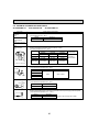
6-5. TROUBLE CRITERION OF MAIN PARTS
SLZ-KA09NA.TH
SLZ-KA12NA.TH
SLZ-KA15NA.TH
Part name
Check method and criterion
Room temperature
thermistor
(TH1)
Measure the resistance with a tester.
(Part temperature 50°F ~ 86°F)
Pipe temperature
thermistor/liquid
(TH2)
Condenser/evaporator
temperature thermistor
(TH5)
Normal
Abnormal
4.3k~9.6k
Opened or short-circuited
Measure the resistance between the terminals with a tester.
(Coil wiring temperature 50°F ~ 86°F)
Indoor fan motor
(MF)
Normal
KA09NA
KA12NA
KA15NA
WHT-BLK
387~418
303~328
272~295
P
BLK BLU YLW BRN RED ORN
WHT
Abnormal
BLK-BLU
77~83
105~114
79~85
Opened or
BLU-YLW
19~21
39~42
37~40
short-circuited
YLW-RED
RED-BRN
179~193
235~254
191~206
# : Thermal fuse 284°F±36F
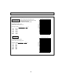
Vane motor (MV)
White Measure the resistance between the terminals with a tester.
(At the ambient temperature 68°F ~ 86°F)
Connector
M
Red — Blue
Red Blue
Yellow
Drain pump (DP)
Yellow
Yellow
Abnormal
300
Open or short
Red — Yellow
Orange Normal
Relay
connector
Red — Orange
Red — White
Measure the resistance between the terminals with a tester.
(At the ambient temperature 68°F ~ 86°F)
1
Normal
Abnormal
2
290
Open or short
Drain sensor (DS)
1
2
3
Measure the resistance between the terminals with a tester.
Measure the resistance after 3 minutes have passed since the power supply was intercepted.
(At the ambient temperature 32°F ~ 140°F)
Normal
Abnormal
0.6k~6.0k
Open or short
20
(Refer to the next page for a detail.)
<Thermistor characteristic graph>
Thermistor for
lower temperature
30_F
50_F
70_F
80_F
90_F
100_F
1
273+(t-32)/1.8
50
40
Resistance (k)
Thermistor R0=15k' ± 3%
Fixed number of B=3480 ± 2%
Rt=15exp { 3480(
< Thermistor for lower temperature >
• Room temperature thermistor (TH1)
• Pipe temperature thermistor/liquid (TH2)
• Condenser/evaporator
temperature thermistor (TH5)
1 )}
273
15.8k'
9.6k'
6.0k'
4.8k'
3.9k'
3.2k'
0
-20
10
20
40
60
80
Temperature (°F)
100
120
< Thermistor for drain sensor >
8
7
1 )}
273
Resistance (k)
1
273+(t-32)/1.8
0
9
Thermistor R0=6.0k' ±5%
Fixed number of B=3390 ± 2%
30_F
50_F
70_F
80_F
90_F
100_F
20
10
Thermistor for
drain sensor
Rt=6exp { 3390(
30
6.3k'
3.9k'
2.5k'
2.0k'
1.6k'
1.3k'
6
5
4
3
2
1
0
20
40
60
80
100
120
Temperature (°F)
21
140 170
6-6. FUNCTIONS OF DIP SWITCH AND JUMPER WIRE
Each function is controlled by the dip switch and the jumper wire on control P.C. board.
Model setting and capacity setting are memorised in the nonvolatile memory of the indoor controller board.
The black square (■) indicates a switch position.
Jumper wire (
Jumper wire
Functions
Setting by the dip switch and jumper wire
MODELS
SLZ-KA09NA.TH
SW2
Capacity
settings
SLZ-KA12NA.TH
SLZ-KA15NA.TH
J41
J42
Pair number
setting with
IR wireless
remote
controller
JP1
Unit type
setting
: Open)
Remarks
Setting
1 2 3 4 5
1 2 3 4 5
1 2 3 4 5
ON
OFF
ON
OFF
ON
OFF
<Initial setting>
IR wireless remote controller: 0
Control PCB: (for both J41 and J42)
Four pair number settings are supported.
The pair number settings of the IR wireless remote
controller and indoor control PCB (J41/J42) are
given in the table on the left.
(' ' in the table indicates the jumper wire is disconnected.)
Wireless remote Control PCB setting
controller setting
J41
J42
0
1
2
3~9
Model
Without TH5
With TH5
: Short
JP1
There is no jumper (JP1) because these models
have the cond./eva. temperature thermistor (TH5).
22
7
SPECIAL FUNCTION
7-1. Rotation Function (and back-up function, 2nd stage cut-in function)
This function is only available when using wired remote controller.
7-1-1. Operation
(1) Rotation function (and Back-up function)
Outline of functions
· Main and sub units operate alternately according to the interval of rotation setting.
w Main and sub unit should be set by refrigerant address. (Outdoor Dip switch setting)
Refrigerant address "00"
Main unit
Refrigerant address "01"
Sub unit
· When error occurs to one unit, another unit will start operation. (Back-up function)
System constraint
· This function is available only by the grouping control system (INDOOR UNIT: OUTDOOR UNIT=1:1) of 2 refrigerant
groups. (Refer to Fig. 1)
· Main indoor unit should be connected for wired remote controller and the transmission line (TB5) for main and sub unit
should also be connected. (Refer to Fig. 1)
(This function cannot be set by wireless remote controller.)
· Set refrigerant address of each unit. (Dip switch on the outdoor unit ··· Refrigerant address 00/01)
Fig. 1
Operation pattern
[Back-up function only]··· Request code number "312"
Error occurs on main unit.
Main
Sub
Start operation
Main
unit
IC-1
Sub
unit
IC-2
Refrigerant address
"00"
Run
Abnormal condition
Stop
Run
3(2)
2
Start operation
Sub
unit
IC-2
3(2)
Main
Sub
Sub
Error occurs on main unit.
Main Main
Sub
Abnormal condition
Run
Stop
Run
Stop
Run
Stop
1~28 days
Sub
unit
IC-2
IC-1
[Rotation function] & [Back-up function]··· Request code number "313~318"
Main
unit
IC-1
OC-2
OC-1
Main
unit
Refrigerant address
"01"
2
RC
OC : Outdoor unit
IC : Indoor unit
RC : Wired remote controller
Run
1~28 days
(Ex:When the request code number is "313", each unit operates alternately in daily cycle.)
Note:
· When the unit is restarted to operate after turning off the power or OFF operation, the unit which was operating will start operation.
· To operate the main unit, refer to the 7-1-2. and set the request code No. which is not the same as the current one, and set
again the former request code No.
(2) 2nd stage cut-in function
Outline of functions
· When the 1st unit can NOT supply with sufficient capacity for exceptionally high-demand conditions and the actual room
temperature reaches set point *, the 2nd unit starts operation in conjunction with the 1st unit.
· Once the actual room temperature goes down to 4 degrees C (7.5 degrees F) below set point*, the 2nd unit stops operation
automatically.
(* set point = set temperature by R/C (remote controller) + 4, 6, 8:(7.5, 10.8, 14.4°F) (selectable))
· Number of operating units is determined according to the room temperature and set point.
· When room temperature becomes higher than set point, standby unit starts. (2 units operation)
· When room temperature falls below set point -4:(-7.5°F), standby unit stops. (1 unit operation)
23
System constraint
· This function is available only in cooling mode.
Ex.) Set temp. by R/C = 20:(68°F)
Set point = 26:(79°F)
When request code number is “323”.
[2nd stage cut-in function]··· Request code number "322~324"
Start operation
26:
(79°F)
22:
(71.5°F)
2nd unit Cut-in
4 degree C
(7.5 degreeF)
2nd unit Cut-out
Main
unit
IC-1
Sub
unit
IC-2
Room temp. Set point
Sub unit start operation
Run
Stop
Run
20:
(68°F)
7-1-2. How to set rotation function (Back-up function, 2nd stage cut-in function)
You can set these functions by wired remote controller. (Maintenance monitor)
NOTE
Both main and sub unit should be set in same setting.
Every time replacing indoor controller board for servicing, the function should be set again.
(1) Request Code List
Rotation setting
Setting No.
(Request code)
No.1
(310)
No.2
(311)
No.3
(312)
No.4
(313)
No.5
(314)
No.6
(315)
No.7
(316)
No.8
(317)
No.9
(318)
Initial
setting
Setting contents
Monitoring the request code of current setting.
Rotation and Back-up OFF (Normal group control operation)
Back-up function only
Rotation ON (Alternating interval = 1 day) and back up function
Rotation ON (Alternating interval = 3 day) and back up function
Rotation ON (Alternating interval = 5 day) and back up function
Rotation ON (Alternating interval = 7 day) and back up function
Rotation ON (Alternating interval = 14 day) and back up function
Rotation ON (Alternating interval = 28 day) and back up function
2nd stage cut-in setting
Setting No.
(Request code)
No.1
(320)
No.2
(321)
No.3
(322)
No.4
(323)
No.5
(324)
Room temp. < Set point -4(-7.5°F)
Sub unit stop
Initial
setting
Setting contents
Monitoring the request code of current setting.
Cut-in function OFF
Cut-in Function ON (Set point = Set temp.+ 4°C (7.5°F))
Cut-in Function ON (Set point = Set temp.+ 6°C (10.8°F))
Cut-in Function ON (Set point = Set temp.+ 8°C (14.4°F))
24
Stop
(2) Setting method of each function by wired remote controller
B: Refrigerant address
C: Data display area
D: Request code display area
1. Stop operation(
).
2. Press the TEST button () for 3 seconds so that [Maintenance mode] appears on the screen ().
After a while, [00] appears in the refrigerant address number display area.(at )
3. Press the CHECK button () for 3 seconds to switch to [Maintenance monitor].
Note) It is not possible to switch to [Maintenance monitor] during data request in maintenance mode
(i.e., while “----” is blinking) since no buttons are operative.
[----] appears on the screen () when [Maintenance monitor] is activated.
(The display () now allows you to set a request code No.)
4. Press the [TEMP (
[ScreenB]
5. Press the [CLOCK (
and
)] buttons () to select the desired refrigerant address.
and
)] buttons () to set the desired request code No.(“311~318”, “321~324”)
6. Press the FILTER button () to perform function setting.
If above setting operations are done correctly, "Request code number" will appear in data display area.()
[Example: When the "311" of "Request code number" is set, [311] appears on the screen.()]
[Refererence]
You can check current "request code number" setting by setting the "request code number"(“310” or “320”) and
pressing the FILTER button.()
[Example: When the current setting is "Setting No.2(Request code 311)", [311] appears on the screen.()]
7. To return to normal mode, press the ON/OFF button (
).
7-2. BACK-UP HEATING FUNCTION (CN152)
Temperature difference
(Z=Set temp. - Room temp.)
7-2-1. Operation
Outline of functions
The back-up heater signal is sent out according to the temperature difference between indoor room temperature and set temperature. This function is available only in heating operation.
Back-up heater
signal output
1
Z 0˚C(˚F)
OFF
2
0 < Z < 2.5˚C(4.5˚F)
Keeping condition
3
2.5˚C(4.5˚F) Z
ON
ON
7-2-2. How to connect
When connecting to the connector CN152 of the indoor unit, use
PAC-SE59RA-E (optional parts).
25
Z
0
2.5˚C(4.5˚F)
OFF
8
4-WAY AIR FLOW SYSTEM
8-1. FRESH AIR INTAKE (LOCATION FOR INSTALLATION)
At the time of installation, use the duct holes (cut out) located at the positions shown in following diagram, as and when required.
Fresh air intake
Fresh air intake hole diagram
3 - W1/8
Burring hole
W3-15/16
Burring hole pitch
120"
120"
4-21/32
(Unit : inch)
W2-7/8
(Cut out hole)
Ceiling surface
Refrigerant pipe
Electrical Box
Drain pipe
8-2. FRESH AIR INTAKE AMOUNT & STATIC PRESSURE CHARACTERISTICS
SLZ-KA09NA.TH
SLZ-KA12NA.TH
SLZ-KA15NA.TH
Taking air into the unit
100
Air flow : Q [CFM]
120
Duct characteristics
at site
Curve in the
left graphs
A
0
C
1
B
Static pressure : P [in. W.G.%10-2]
20
20
40
60
80
0
How to read curves
Q
-20
2
C
A
-40
E
-60
Q
-80
-100
D
3
A
-120
NOTE: Fresh air intake amount should be 20% or less of
whole air amount to prevent dew dripping.
Q…Designed amount of fresh air intake
<CFM>
A…Static pressure loss of fresh air
intake duct system with air flow
amount Q
<in. W.G.o10-2>
…
B Forced static pressure at air conditioner inlet with air flow amount Q
<in. W.G.o10-2>
C…Static pressure of booster fan with
air flow amount Q <in. W.G.o10-2>
D … Static pressure loss increase
amount of fresh air intake duct system for air flow amount Q
<in. W.G.o10-2>
…
E Static pressure of indoor unit with
air flow amount Q <in. W.G.o10-2>
Qa…Estimated amount of fresh air
intake without D
<CFM>
Q
Qa
8-3. OPERATION IN CONJUNCTION WITH DUCT FAN (BOOSTER FAN)
● Whenever the indoor unit operates, the
duct fan operates.
(1)Connect the optional multiple remote
controller adapter(PAC-SA88HA-E)
to the connector CN51 on the indoor
controller board.
(2)Drive the relay after connecting the
12V DC relay between the Yellow
and Orange connector wires.
Use a nonpolar relay of 1W or smaller.
MB: Electromagnetic switch power
relay for duct fan.
X: Auxiliary relay (12V DC LY-1F)
CN51
on
indoor unit
board
5
Green
Be sure to secure insulation
material by tape, etc.
~
Yellow
1
Connector (5P)
Indoor unit side
Orange
Red
Brown
Multiple remote
controller adapter
PAC-SA88HA-E
+
MB
Installation at site
Be sure to secure insulation
material by tape, etc.
Indoor controller board
Multiple remote
controller adapter
PAC-SA88HA-E
Distance between indoor
controller board and relay
must be within 10m.
CN51(WHT)
CN51
26
8-4. FIXING HORIZONTAL VANE
Horizontal vane of each air outlet can be fixed according to the environment where it is installed.
Setting procedure
1) Turn off a main power supply (Turn off a breaker).
2) Remove the vane motor connector in the direction of the arrow shown below with pressing the unlocking button as in the
figure below.
Insulate the disconnected connector with the plastic tape.
Vane motor
Vane motor
Connector
Unlocking button
Horizontal vane
3) Set the vertical vane of the air outlet by hand slowly within the range in the table below.
Measured standard position of the grille
Horizontal vane
< Specified range >
Up/down airflow
direction
Horizontal 30°
Downward 45°
Downward 55°
Downward 70°
A
21 mm
13/16 inch
25 mm
31/32 inch
28 mm
1-3/32 inch
30 mm
1-3/16 inch
· The vanes can be set between 21mm, 13/16 inch and 30 mm, 1-3/16 inch.
Caution:
Do not set the up/down vanes passed the specified range. Condensation could form and drop from the ceiling,
or the unit could malfunction.
27
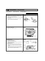
9
DISASSEMBLY PROCEDURE
SLZ-KA09NA.TH
SLZ-KA12NA.TH
SLZ-KA15NA.TH
Be careful when removing heavy parts.
OPERATING PROCEDURE
PHOTOS & ILLUSTRATIONS
1. Removing the air intake grille
(1) Slide the knob of air intake grille to the direction of the
arrow 1 to open the air intake grille.
(2) Remove the string hook from the panel to prevent the grille
from dropping.
(3) Slide the hinge of the intake grille to the direction of the
arrow 2 and remove the air intake grille.
Figure 1
Air intake grille
Grille
Air intake grille knob
2. Removing the fan guard
(1) Open the air intake grille.
(2) Remove the 3 screws of fan guard.
Photo 1
Fan guard
Screws
Air intake grille
3. Removing the panel
(1) Remove the air intake grille. (Refer to step 1)
Corner panel (See Figure 2)
(1) Remove the screw of the corner.
(2) Slide the corner panel to the direction of the arrow 3, and
remove the corner panel.
Panel (See Photo 2)
(1) Disconnect the connector that connects with the unit.
(2) Remove the 2 screws from the panel and loose another
2 screws, which are fixed to the oval hole, have different
diameter.
(3) Rotate the panel a little to remove the screws. (Slide the
panel so that the screw comes to a larger diameter of the
oval hole, which has 2 different diameters.)
Figure 2
Corner
Screw panel
Corner
panel
Panel
Photo 2
Screws
Connectors
Screws
Panel
28
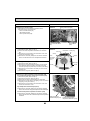
OPERATING PROCEDURE
PHOTOS & ILLUSTRATIONS
Photo 3
4. Removing the electrical parts
(1) Remove the 2 screws and the control box cover.
<Electrical parts in the control box>
• Indoor controller board (I.B)
• Terminal block (TB4)
• Indoor power board (P.B)
Indoor power board (P.B)
Photo 4
Terminal block
(TB4)
Indoor controller board
(I.B)
5. Removing the room temperature thermistor (TH1)
(1) Remove the panel. (Refer to step 3)
(2) Pull out the room temperature thermistor from the drain
pan.
(3) Remove the 2 screws fixed to the control box cover, and
remove the control box cover.
(4) Remove the connector (CN20) from the indoor controller
board, and disconnect the room temperature thermistor.
6. Removing the drain pan
(1) Remove the panel. (Refer to step 3)
(2) Remove the room temperature thermistor and the 2 lead
wires held with fastener; wireless controller board relay
connector (9P red) and panel relay connector (10P white).
(3) Remove the 4 screws fixed to the drain pan, and remove
the drain pan.
(4) Remove the fan guard. (Refer to step 2)
7. Removing the pipe temperature thermistor/liquid (TH2)
and condenser/evaporator temperature thermistor (TH5)
(1) Remove the panel. (Refer to step 3)
(2) Remove the drain pan. (Refer to step 6)
(3) Disconnect the indoor coil thermistor from the holder.
(4) Remove the 3 screws fixed to the piping cover, and remove
the piping cover. (See Photo 9)
(5) Remove the 2 screws fixed to the control box cover, and
remove the control box cover.
Photo 4
Control box
Connectors
Drain plug
Screw
Screw
Room
temperature
thermistor
(TH1)
Drain pan
Screw
Screw
Fan guard
Photo 5
Control box
Pipe temperature thermistor/liquid (TH2)
(6) Remove the connector (CN21) from the indoor controller
board, and disconnect the pipe temperature thermistor/liquid.
Condenser/evaporator temperature thermistor (TH5)
(6) Remove the connector (CN29) from the indoor controller
board, and disconnect the condenser/evaporator temperature
thermistor.
29
Pipe temperature
thermistor/liquid (TH2)
Condenser/evaporator
temperature thermistor (TH5)
OPERATING PROCEDURE
PHOTOS & ILLUSTRATIONS
8. Removing the fan motor (MF)
(1) Remove the panel. (Refer to step 3)
(2) Remove the drain pan. (Refer to step 6)
(3) Remove the nut and the washer from the turbo fan, and
remove the turbo fan.
(4) Remove the 2 screws fixed to the control box cover, and
remove the control box cover.
(5) Disconnect the connectors of the (fan 1) and the (fan 2)
from the indoor controller board.
(6) Remove the 3 screws fixed to the piping cover, and remove
the piping cover. (See Photo 9)
(7) Remove the 6 screws fixed to the flat plate, and remove
the flat plate.
(8) Disconnect the lead wires to the direction of the fan motor,
and remove the 3 nuts of the fan motor.
9. Removing the drain pump (DP) and drain sensor (DS)
(1) Remove the panel. (Refer to step 3)
(2) Remove the drain pan. (Refer to step 6)
(3) Remove the 2 screws fixed to the control box cover, and
remove the control box cover.
(4) Remove the connectors of the (CNP) and the (CN31)
from the indoor controller board.
(5) Remove the 1 screw fixed to the cover, and remove the
cover.
(6) Disconnect the lead wires to the direction of the drain
pump. (See Photo 7)
(7) Remove the 3 screws of the drain pump.
(8) Cut the drain hose band, pull out the drain hose from the
drain pump.
(9) Pull out the drain pump.
(10) Remove the drain sensor and the holder.
Photo 6
Flat plate
Screw
Screws
Nut
Fan motor
(MF)
Nut
Lead
wires
Screws
Screw
Photo 7
Nut
Screw
Cover
Control
box
Lead wires
Photo 8
Drain sensor (DS)
Drain pump (DP)
Drain
hose
Screws
Screw
30
Fixing band
Control box
OPERATING PROCEDURE
PHOTOS & ILLUSTRATIONS
10. Removing the heat exchanger
(1) Remove the panel. (Refer to step 3)
(2) Remove the drain pan. (Refer to step 6)
(3) Remove the nut and the washer from the turbo fan, and
remove the turbo fan.
(4) Remove the 2 screws fixed to the control box cover, and
remove the control box cover.
(5) Disconnect the connector of the (fan) from the indoor controller board.
(6) Remove the 3 screws fixed to the piping cover, and remove
the piping cover. (See Photo 9)
(7) Remove the pipe temperature thermistor/liquid and
condenser/evaporator temperature thermistor. (Refer to
step 7)
(8) Disconnect the lead wires to the direction of the fan motor.
(9) Remove the 1 coil support screw, the 2 inside coil screws
(See Photo 10), and the 4 outside coil screws (See Photo 9)
from the heat exchanger, and remove the heat exchanger.
Photo 9
Screws of
piping cover
Coil
screws
Coil
screws
Piping cover
Lead wires
Control box
Photo 10
Coil screws
Coil
support
Coil
support
Screw
Heat exchanger
31
HEAD OFFICE : TOKYO BLDG., 2-7-3, MARUNOUCHI, CHIYODA-KU, TOKYO 100-8310, JAPAN
CCopyright 2010 MITSUBISHI ELECTRIC ENGINEERING CO., LTD.
Distributed in Nov. 2010 No.OCH487
Made in Japan
New publication, effective Nov. 2010
Specifications subject to change without notice.