1
Builder Rear Vent Direct Vent
Models: 33LDVR, 36LDVR,
39LDVR, 43LDVR
INSTALLER/CONSUMER
SAFETY INFORMATION
PLEASE READ THIS MANUAL
BEFORE INSTALLING AND USING
APPLIANCE
WARNING!
IF THE INFORMATION IN THIS
MANUAL IS NOT FOLLOWED
EXACTLY, A FIRE OR EXPLOSION
MAY RESULT CAUSING
PROPERTY DAMAGE, PERSONAL
INJURY OR LOSS OF LIFE.
FOR YOUR SAFETY
Installation and service must be
performed by a qualified installer,
service agency or the gas supplier.
WHAT TO DO IF YOU SMELL GAS:
• Do not try to light any appliance.
• Do not touch any electric switch; do
not use any phone in your building.
• Immediately call your gas supplier
from your neighbor’s phone. Follow
the gas suppliers instructions.
• If you cannot reach your gas
supplier call the fire department.
DO NOT STORE OR USE
GASOLINE OR OTHER
FLAMMABLE VAPORS AND
LIQUIDS IN THE VICINITY OF THIS
OR ANY OTHER APPLIANCE.
Installation Instructions and
Homeowner’s
7317 Manual
LDVR COVER
1/05
- Ê
,/ ,/Ê
INSTALLER: Leave this manual with the appliance.
CONSUMER: Retain this manual for future reference.
10007317 1/13 Rev. 17
LDVR Series Direct Vent Gas Fireplace
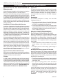
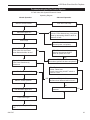
Table of Contents
PLEASE READ THE INSTALLATION & OPERATING INSTRUCTIONS BEFORE USING APPLIANCE.
Thank you and congratulations on your purchase of an Vermont Castings Group fireplace.
IMPORTANT: Read all instructions and warnings carefully before starting installation.
Failure to follow these instructions fully may result in a possible fire hazard and will void the warranty.
Installation & Operating Instructions
General Venting Information
Operating Instructions
Maintenance
Replacement Parts Optional Accessories
Warranty Energuide General Information, Cautions, Warning........................................................................3
Requirements for the Commonwealth of Massachusetts..............................................4
Fireplace Dimensions.....................................................................................................5
Locating Your Fireplace.................................................................................................6
Clearance to Combustibles............................................................................................6
Mantels...........................................................................................................................6
Hearth............................................................................................................................7
Framing and Finishing...................................................................................................7
Final Finishing................................................................................................................7
Gas Specifications.........................................................................................................7
Air Shutter Adjustment...................................................................................................7
Gas Inlet and Manifold Pressures..................................................................................7
High Elevations..............................................................................................................8
Gas Line Installation......................................................................................................8
Remote ON/OFF Switch................................................................................................8
Alternate Switch Location..............................................................................................8
EB-1 Electrical Box........................................................................................................9
Electronic Gas Control Valve.........................................................................................9
Wiring Diagrams...........................................................................................................10
General Venting........................................................................................................... 11
General Venting Information-Termination Location......................................................12
General Information Assembling Vent Pipes................................................................13
How to Use the Vent Graph.........................................................................................14
Rear Wall Venting Applications & Installation...............................................................14
Vertical Sidewall Applications & Installation.................................................................16
Below Grade Installation..............................................................................................19
Vertical Through-the-Roof Applications & Installation..................................................20
Venting Components....................................................................................................23
Glass Information.........................................................................................................24
Louvre Removal...........................................................................................................24
Window Frame Assembly Removal.............................................................................24
Glass Cleaning.............................................................................................................24
Installation of Logs, Lava Rock & Ember Material.......................................................25
Flame & Temperature Adjustment................................................................................27
Flame Characteristics..................................................................................................27
Lighting and Operating Instructions (SIT820 Valve).....................................................29
Lighting and Operating Instructions (SIT822 Valve).....................................................30
Lighting and Operating Instructions (AF4000 Valve)....................................................31
Troubleshooting (SIT820 Valve)...................................................................................32
Troubleshooting (SIT822 Valve)...................................................................................33
Troubleshooting (AF4000 Valve)..................................................................................34
Gas Control System Error Codes (AF4000 Valve).......................................................36
Fuel Conversion Instructions.......................................................................................37
Cleaning the Standing Pilot Control System................................................................39
.....................................................................................................................................40
Fan Kits........................................................................................................................43
Ceramic Refractory Lining............................................................................................44
Remote Controls..........................................................................................................44
Trim Kits.......................................................................................................................45
Screen Door Kits..........................................................................................................45
Filigree Louvre Kits......................................................................................................45
.....................................................................................................................................47
.....................................................................................................................................48
10007317
LDVR Series Direct Vent Gas Fireplace
Installation & Operating Instructions
This gas fireplace should be installed by a qualified installer,
preferably NFI or WETT (Canada) certified, in accordance with
local building codes and with current CSA-B149.1 Installation
codes for Gas Burning Appliances and Equipment. For USA
Installations follow local codes and/or the current National Fuel
Gas Code. ANSI Z223.1/NFPA 54.
FOR SAFE INSTALLATION AND OPERATION PLEASE NOTE
THE FOLLOWING:
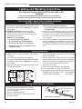
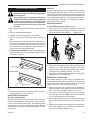
1. This fireplace gives off high temperatures and should be located
out of high traffic areas and away from furniture and draperies.
2. Children and adults should be alerted to the hazards of high
surface temperatures of this fireplace and should stay away
to avoid burns or ignition of clothing.
3. CAUTION: Due to high glass surface temperature children
should be carefully supervised when in the same room as
fireplace.
7!2.).'
(/4',!337),,
#!53%"52.3
$/./44/5#(',!33
5.4),#//,%$
.%6%2!,,/7#(),$2%.
4/4/5#(',!33
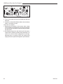
4. Under no circumstances should this fireplace be modified. Parts
removed for servicing should be replaced prior to operating
this fireplace again.
5. Installation and any repairs to this fireplace must be performed
by a qualified installer, service agency or gas supplier. A professional service person should be contacted to inspect this
fireplace annually. Make it a practice to have all of your gas
fireplaces checked annually. More frequent cleaning may be
required due to excess lint and dust from carpeting, bedding
material, etc.
6. Control compartments, burners and air passages in this fireplace
should be kept clean and free of dust and lint. Make sure the
gas valve and pilot light are turned off before you attempt to
clean this fireplace.
7. The venting system (chimney) of this fireplace should be checked
at least once a year and if needed your venting system should
be cleaned.
8. Keep the area around your fireplace clear of combustible
materials, gasoline and other flammable vapor and liquids.
This fireplace should not be used as a drying rack for clothing,
nor should Christmas stockings or decorations be hung on or
around the fireplace.
9. Under no circumstances should any solid fuels (wood, coal,
paper or cardboard etc.) be used in this fireplace.
10.The flow of combustion and ventilation air must not be obstructed
in any way.
11.When fireplace is installed directly on carpeting, vinyl tile or
any combustible material other than wood, the fireplace must
be installed on a metal or wood panel extending the full width
and depth of the fireplace.
10007317
12.This fireplace requires adequate ventilation and combustion
air to operate properly.
13.This fireplace must not be connected to a chimney flue serving
a separate solid fuel burning fireplace.
14.When the fireplace is not in use it is recommended that the
gas valve be left in the OFF position.
15.These units have been approved for bedroom use.
WARNING: Check with your electronics manufacturer
before installing a television or other electronic device
above this fireplace.
33LDVR / 36LDVR / 39LDVR / 43LDVR
Certified To
ANSI Z21.88-2009 / CSA 2.33-2009
Vented Gas Fireplace Heaters
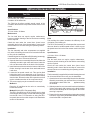
IMPORTANT:
PLEASE REVIEW THE FOLLOWING CAREFULLY
Remove any plastic from trim parts before turning the
fireplace ON.
It is normal for fireplaces fabricated of steel to give off
some expansion and/or contraction noises during the
start up or cool down cycle. Similar noises are found
with your furnace heat exchanger or car engine.
It is not unusual for your gas fireplace to give off some
odor the first time it is burned. This is due to the curing of
the paint and any undetected oil from the manufacturing
process.
Please ensure that your room is well ventilated open all windows.
It is recommended that you burn your fireplace for at
least ten (10) hours the first time you use it. If the optional
fan kit has been installed, place the fan switch in the
“OFF” position during this time.
This appliance may be installed in an aftermarket
permanently located, manufactured home or mobile
home, where not prohibited by local codes.
This appliance is only for use with the type of gas
indicated on the rating plate. This appliance is not
convertible for use with other gases, unless a certified
kit is used.
The LDVR has been approved for mobile home
installations.
Proposition 65 Warning: Fuels used in gas, woodburning or oil fired appliances, and the products of
combustion of such fuels, contain chemicals known to
the State of California to cause cancer, birth defects
and other reproductive harm.
California Health & Safety Code Sec. 25249.6
LDVR Series Direct Vent Gas Fireplace
Installation & Operating Instructions
Requirements for the Commonwealth of
Massachusetts
All gas fitting and installation of this heater shall only be
done by a licensed gas fitter or licensed plumber.
For all side wall horizontally vented gas fueled equipment
installed in every dwelling, building or structure used in whole
or in part for residential purposes, including those owned
or operated by the Commonwealth and where the side wall
exhaust vent termination is less than seven (7) feet above
finished grade in the area of the venting, including but not
limited to decks and porches, the following requirements
shall be satisfied:
Installation of Carbon Monoxide Detectors
At the time of installation of the side wall horizontal vented
gas fueled equipment, the installing plumber or gas fitter
shall observe that a hard wired carbon monoxide detector
with an alarm is installed on each additional level of the
dwelling, building or structure served by the side wall
horizontally vented gas fueled equipment. It shall be the
responsibility of the property owner to secure the services
of qualified licensed professionals for the installation of
hard wired carbon monoxide detectors.
In the event that the side wall horizontally vented gas fueled
equipment is installed in a crawl space or an attic, the hard
wired carbon monoxide detector with alarm and battery
back-up may be installed on the next adjacent floor level.
In the event that the requirements of this subdivision can not
be met at the time of completion of installation, the owner
shall have a period of thirty (30) days to comply with the
above requirements; provided, however, that during said
thirty (30) day period, a battery operated carbon monoxide
detector with an alarm shall be installed.
Approved Carbon Monoxide Detectors
Each carbon monoxide detector as required in accordance
with the above provisions shall comply with NFPA 720 and
ANSI/UL 2034 listed and IAS certified.
Signage
A metal or plastic identification plate shall be permanently
mounted to the exterior of the building at a minimum height
of eight (8) feet above grade directly in line with the exhaust
vent terminal for the horizontally vented gas fueled heating
appliance or equipment. The sign shall read, in print size no
less than one-half (1/2) inch in size, “GAS VENT DIRECTLY
BELOW, KEEP CLEAR OF ALL OBSTRUCTIONS”.
Inspection
The state or local gas inspector of the side wall horizontally
vented gas fueled equipment shall not approve the
installation unless, upon inspection, the inspector observes
carbon monoxide detectors and signage installed in
accordance with the provisions of 248 CMR 5.08(2)(a)1
through 4.
Exemptions
The following equipment is exempt from 248 CMR
5.08(2)(a)1 through 4:
• The equipment listed in Chapter 10 entitled “Equipment
•
Not Required To Be Vented” in the most current edition
of NFPA 54 as adopted by the Board; and
Product Approved side wall horizontally vented gas fueled
equipment installed in a room or structure separate from
the dwelling, building or structure used in whole or in
part for residential purposes.
MANUFACTURER REQUIREMENTS
Gas Equipment Venting System Provided
When the manufacturer of Product Approved side wall
horizontally vented gas equipment provides a venting
system design or venting system components with the
equipment, the instructions provided by the manufacturer
for installation of the equipment and the venting system
shall include:
• Detailed instructions for the installation of the venting
•
system design or the venting system components;
and
A complete parts list for the venting system design or
venting system.
Gas Equipment Venting System NOT Provided
When the manufacturer of a Product Approved side wall
horizontally vented gas fueled equipment does not provide
the parts for venting the flue gases, but identifies “special
venting systems”, the following requirements shall be
satisfied by the manufacturer:
• The referenced “special venting system” instructions shall
•
be included with the appliance or equipment installation
instructions; and
The “special venting systems” shall be Product
Approved by the Board, and the instructions for that
system shall include a parts list and detailed installation
instructions.
A copy of all installation instructions for all Product Approved
side wall horizontally vented gas fueled equipment, all
venting instructions, all parts lists for venting instructions,
and/or all venting design instructions shall remain with
the appliance or equipment at the completion of the
installation.
10007317
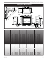
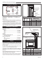
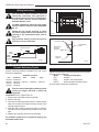
LDVR Series Direct Vent Gas Fireplace
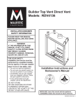
Fireplace Dimensions
Rough
Opening
Depth
S
E
R
F
S
U
V - Rough Opening Width
Rough
Opening
Height
T
Low
Voltage
Access
B
Q
Gas Line
Access
Centerline of
7" Collar
C
D
M
O
P
M
A
Gas Line
Access
Electrical
Access
Low
Voltage
Electrical
Access
J
K
L
#
,
I
H
N
G
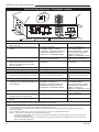
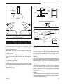
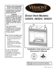
Fig. 1 Fireplace specifications and framing dimensions.
Ref.
33LDVR
36LDVR
39LDVR
43LDVR
A
33”
(838 mm)
36” (914 mm)
39” (991 mm)
43” (1092 mm)
B28⁷⁄₈” (733 mm)
34¹⁄₄” (870 mm)
34¹⁄₄” (870 mm)
37” (940 mm)
C
31¹⁄₄” (794 mm)
34¹⁄₄” (870 mm)
37¹⁄₄” (946 mm)
41¹⁄₄” (1048 mm)
D
18³⁄₈” (466 mm)23” (584 mm)23” (584 mm)25³⁄₄” (654 mm)
E24⁷⁄₈” (632 mm)24” (610 mm)27” (686 mm)
31” (788 mm)
F
11¹⁄₂” (292 mm)
16” (406 mm)
16” (406 mm)
16” (406 mm)
G
14¹⁄₄” (362 mm)
18³⁄₄” (476 mm)
18³⁄₄” (476 mm)
18³⁄₄” (476 mm)
H
19³⁄₄” (501 mm)24¹⁄₄” (616 mm)24¹⁄₄” (616 mm)27” (686 mm)
I23¹⁄₄” (590 mm)27³⁄₄” (705 mm)27³⁄₄” (705 mm)
30¹⁄₂” (775 mm)
J
4³⁄₄”
(121 mm)
5⁵⁄₈” (143 mm)
5⁵⁄₈” (143 mm)
5⁵⁄₈” (143 mm)
K
6⁵⁄₁₆”
(160 mm)
8” (203 mm)
8” (203 mm)
8” (203 mm)
L
8⁷⁄₈”
(225 mm)
11⁷⁄₈” (302 mm)
11⁷⁄₈” (302 mm)
11⁷⁄₈” (302 mm)
M2”
(51 mm)2” (51 mm)2” (51 mm)2”
(51 mm)
N
3³⁄₈”
(86 mm)
3¹⁄₄” (83 mm)
3¹⁄₄” (83 mm)
3¹⁄₄” (83 mm)
O
4³⁄v”
(121 mm)
6³⁄₄” (172 mm)
6³⁄₄” (172 mm)
6³⁄₄” (172 mm)
P
6⁵⁄zn”
(160 mm)
9¹⁄₄” (235 mm)
9¹⁄₄” (235 mm)
9¹⁄₄” (235 mm)
Framing Dimensions
10007317
Q29B\,”
R
12”
S
36”
T
51”
U25¹⁄₂”
V
33¹⁄₂”
(753 mm)
35” (889 mm)
(305 mm)
16¹⁄₂” (419 mm)
(914 mm)
41⁵⁄₈” (1057 mm)
1295 mm)
58⁷⁄₈” (1495 mm)
(648 mm)29⁷⁄₈“ (748 mm)
(851 mm)
36¹⁄₂” (927 mm)
35” (889 mm)
16¹⁄₂” (419 mm)
44” (1118 mm)
62¹⁄₄” (1581 mm)
31¹⁄₈” (790 mm)
39¹⁄₂” (1003 mm)
37³⁄₄”
16¹⁄₂”
44¹⁄₈”
62³⁄₈”
31¹⁄₄”
43¹⁄₂”
(959 mm)
(419 mm)
(1121 mm)
(1584 mm)
(794 mm)
(1105 mm)
LDVR Series Direct Vent Gas Fireplace
Locating Your Fireplace
V
W
X
Y
Y
A
E
X
C
Y
Z
B
A
D
X
B
C
D
3/4” (19 mm) Scribe
Moulding for use with
Vermont Castings
Group Cabinets
E
Fireplace
B
Top Louvre
Assembly
F
Top of Combustion
Chamber
LU584-R
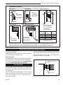
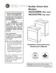
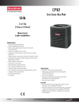
Fig. 2 Locate gas fireplace.
A) Flat on wall D) *Room divider
Y) 6” minimum
B) Cross corner
E) *Flat on wall corner
LU584-R
Locating unit
2/23/01 sta
C) **Island
F) Chase installation
NOTE: (Fig. 2)
** Island (C) and Room Divider (D) installation is possible as long
as the horizontal portion of the vent system (X) does not exceed
20’ (610cm). See details in Venting Section.
* When you install your fireplace in(D) Room divider or (E) Flat
on wall corner positions (Y), a minimum of 6” (153mm) clearance
must be maintained from the perpendicular wall and the front side
edge of the fireplace. Refer to (Y) in Figure 2.
Clearance to Combustibles
Top of Unit to Ceiling................................ 36” (914 mm)
Appliance
Top........................................................... 0” (0 mm)
Bottom...................................................... 0” (0 mm)
Side.......................................................... 0” (0 mm)
Back......................................................... 0” (0 mm)
Venting
Concentric sections of DV Vent
Top, bottom & sides............................... 1” (25 mm)
Rear Vent Applications:
Top......................................................... 2” (50 mm)
Sides and Bottom................................... 1” (25 mm)
Flex Vent............................................. 7/8” (22 mm)
CFM146
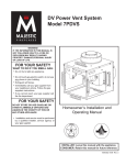
Mantel Chart
CFM146
Mantel Shelf DV Mantel Chart Mantel from Top
7/5/01 sta
Ref. or Breast Plate Ref.
of Combustion Chamber
Depth 36/39/43 LDVR
33LDVR
V 10” (254 mm) A 17” (432 mm) 16Z\x” (419 mm)
W 8” (203 mm) B 15” (381 mm) 14Z\x” (368 mm)
X
6” (152 mm) C 13” (330 mm) 12Z\x” (318 mm)
Y
4” (102 mm) D 11” (279 mm) 10Z\x” (267 mm)
Z2” (51 mm) E 9” (229 mm) 8Z\x” (216 mm)
Fig. 3a Combustible mantel minimum installation.
3/4” (19 mm) Scribe
Moulding for use with
Vermont Castings Group
Cabinets
Black
Surround
Face
CFM164a
J
Mantel
Leg
Side of
Combustion Chamber
CFM164a
Mantel Leg Chart
06/22/01 sta
M
N
O
I
H
G
F
K
L
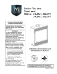
Mantels
The height that a combustible mantel is fitted above the
fireplace is dependent on the depth of the mantel. This also
applies to the distance between the mantel leg (if fitted)
and the fireplace.
For the correct mounting height and widths refer to Figs.
3a and 3b, and the following Mantel Charts.
The fitting of a bay window trim kit does not effect the
distances and reference points referred to in the diagram
and chart.
Noncombustible mantels and legs may be installed at any
height and width around the appliance.
When using paint or lacquer to finish the mantel, such paint or
lacquer must be heat resistant to prevent discoloration.
CFM170
Mantel
Mantel Leg FromSide
Ref.
Leg Depth
Ref.
of Comb. Opening
CFM170
F
10” (254 mm)
K
11¹⁄₂”
(292 mm)
DV Builder Front
View
G
8” (203 mm)
L
9¹⁄₂” (241 mm)
H
6” (152 mm)
M
7¹⁄₂” (191 mm)
I
4” (102 mm)
N
5¹⁄₂” (140 mm)
J2” (51 mm)
O
3¹⁄₂” (89 mm)
Fig. 3b Combustible mantel leg minimum installation.
10007317
LDVR Series Direct Vent Gas Fireplace
Final Finishing
Hearth
A hearth is not mandatory but is recommended for aesthetic purposes. We recommend a noncombustible hearth
which projects out 12” (305mm) or more from the front of
the fireplace.
Cold climate installation recommendation:
When installing this unit against a noninsulated exterior wall or chase, it is
mandatory that the outer walls be insulated
to conform to applicable insulation codes.
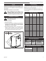
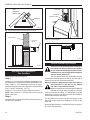
Framing and Finishing Check fireplace to make sure it is levelled
and properly positioned.
To mount the appliance:
1. Choose the location.
2. This unit comes with four (4) flanges pre-mounted on
both sides of the fireplace to allow two different drywall
thicknesses to be used. Flange “A” is for 1/2” drywall
while flange “B” is for 5/8” drywall.
3. Bend the desired flanges out 90° on both sides of the
fireplace. Slide the fireplace into the framed opening
until the flanges contact the front surfaces of the framing. Level the unit and secure it firmly in place.
Flange
Drywall
Position
Depth
A
1/2” / 13 mm
B
5/8” / 16 mm
Flange Location for
Desired Drywall Depth
Noncombustible materials such as brick or tile may be
extended over the edges of the face of the fireplace. DO
NOT cover any vent or grille panels.
If a Trim Kit is going to be installed on the fireplace, the
brick or tile will have to be installed flush with the edges
of the fireplace.
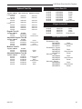
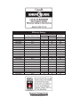
Gas Specifications
Max.
Gas
Input
Model
Fuel
Control
BTU/h
33LDVRRN
Nat
Millivolt
16,000
33LDVRRP
Prop
Millivolt
16,000
33LDVREN
Nat24V Hi/Lo
16,000
33LDVREP
Prop*24V Hi/Lo
16,000
33LDVRIN
Nat. 6V DC Hi/Lo 16,000
33LDVRIP*
Prop.* 6V DC Hi/Lo 16,000
36LDVRRN
Nat
Millivolt
19,500
36LDVRRP
Prop
Millivolt
19,500
36LDVREN
Nat24V Hi/Lo
19,500
36LDVREP
Prop*24V Hi/Lo
19,500
36LDVRIN
Nat. 6V DC Hi/Lo 19,500
36LDVRIP*
Prop.* 6V DC Hi/Lo 19,500
39LDVRRN
Nat
Millivolt23,000
39LDVRRP
Prop*
Millivolt22,500
39LDVREN
Nat24V Hi/Lo23,000
39LDVREP
Prop*24V Hi/Lo22,500
39LDVRIN
Nat. 6V DC Hi/Lo23,000
39LDVRIP*
Prop.* 6V DC Hi/Lo23,000
43LDVRRN
Nat
Millivolt26,000
43LDVRRP
Prop*
Millivolt24,000
43LDVREN
Nat24V Hi/Lo26,000
43LDVREP
Prop*24V Hi/Lo24,000
Min.
Input
BTU/h
11,200
12,000
11,200
12,000
11,200
12,000
13,650
14,625
13,650
14,625
13,650
14,625
16,100
16,875
16,100
16,875
16,100
16,875
18,200
18,000
18,200
18,000
*Using conversion kit
Air Shutter Adjustment
A
Model
Gas Type Air Shutter Opening
33LDV
Natural
3/16” Open
36/39/43LDV
Natural
Top & Bottom Hole Half Closed
33/36/39/43LDV Propane
Fully Open
B
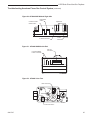
FP1539
Fig. 4 Nailing flanges.
FP1544
nail flange
1/05
10007317
Gas Inlet and Manifold Pressures
Inlet Minimum
Inlet Maximum
Manifold Pressure
Natural
5.5” w.c.
14.0” w.c.
3.5” w.c.
LP (Propane)
11.0” w.c.
14.0” w.c.
10.0” w.c.
LDVR Series Direct Vent Gas Fireplace
High Elevations
Input ratings are shown in BTU per hour and are
certified without deration for elevations up to 4,500
feet (1,370m) above sea level.
For elevations above 4,500 feet (1,370m) in USA,
installations must be in accordance with the current ANSI Z223.1/NFPA 54 and/or local codes having
jurisdiction.
In Canada, please consult provincial and/or local
authorities having jurisdiction for installations at
elevations above 4,500 feet (1,370m).
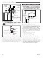
Gas Line Installation
When purging the gas lines, the front window
frame assembly must be removed.
The gas pipeline can be brought in through the rear of the
appliance as well as the bottom. Knockouts are provided
on the bottom behind the valve to allow for the gas pipe
installation and testing of any gas connection. It is most
convenient to bring the gas line in from the rear right side of
the valve as this allows fan installation or removal without
disconnecting the gas line.
The gas line connection can be made with properly tinned
3/8” copper tubing, 3/8” rigid pipe or an approved flex connector. Since some municipalities have additional local
codes, it is always best to consult your local authority and
the National Fuel Gas Code, ANSI Z223.1/NFPA 54 in the
USA or the CSA-B149.1 installation code.
1/2” Gas Supply
1/2” NPT x 1/2” Flare Shutoff Valve
3/8” Flex Line
(From Valve)
The fireplace valve must not be subjected to any test pressures exceeding 1/2 psi. Isolate or disconnect this and
any other gas appliance control from the gas line when
pressure testing.
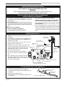
Remote ON/OFF Switch
Installation
1. Thread the wiring through the holes on the end panels
of the fireplace. Take care not to cut the wire or insulation on metal edges. Route the wire to a conveniently
located receptacle box.
2. Attach the wire to the ON/OFF switch and install the
switch into the receptacle box.
3. Connect the other ends of the wire to the gas control
valve. (Fig. 6)
Remote ON/OFF Switch
or Thermostat
or Remote Control
TP
TH
TP
Gas
Control
Valve
TH
FP1224
Fig. 6 Remote switch wiring diagram.
Alternate Switch Location
FP1224
The remote switch canRemote
be installed
on the front/side of the
switch
access door. Simply mount
the
switch
to the bracket provided
11/02
and screw the bracket to either side of the frame, lining up
the screws with the pre-punched holes. (Fig. 7)
FP297A
Fig. 5 Typical gas supply installation.
Always check for gas leaks with a mild soap
and water solution. Do not use an open flame
for leak testing.
FP297A
INSTA
FREE screw type
The gas control is equipped
withVENT
a captured
UVHB26
GAS
SUPPLYto provide
pressure test point, therefore it is not necessary
7/1/98
a 1/8” test point up stream of the control.
When using copper or flex connector use only approved
fittings. Always provide a union when using black iron pipe
so the gas line can be easily disconnected for burner or
fan servicing. See gas specification for pressure details
and ratings.
FP1024
Fig. 7 Alternate switch location.
Do not wire the remote ON/OFF wall switch
for the gas fireplace to the 120 volt power
supply.
FP1024
alternate 10007317
remote switch
location
LDVR Series Direct Vent Gas Fireplace
EB-1 Electrical Box
The fireplace, when installed, must be electrically connected and grounded in accordance
with local codes or, in the absence of local
codes, with the current CSA C22.1 Canadian
Electrical Code.
For USA installations follow local codes and
the national electrical code ANSI/NFPA No.
70.
It is strongly suggested that the wiring of the
EB-1 Electrical Junction Box be carried out
by a licensed electrician.
Ensure that the power to the supply line has
been disconnected before commencing this
procedure.
The EB-1 Electrical junction box has been fitted standard
on this model to allow for the easy connection of an optional fan kit.
To connect the EB-1 box to the house electrical supply
follow the steps below.
1. Unscrew the retaining screw from the EB-1 base plate
and remove the EB-1 assembly from the appliance. (Fig. 8)
2. Remove the front cover of the EB-1 box.
3. Remove the plug socket assembly from the EB-1 box.
4. Feed the supply line in through the EB-1 opening in the
side of the appliance and then through the back of the
EB-1 assembly. (Fig. 8)
5. Connect the black wire of the power supply line to the
brass screw (polarized) of the socket assembly.
6. Connect the white wire of the power line to the chrome
screw of the socket assembly.
7. Connect the ground wire of the supply line to the green
screw of the socket assembly.
8. Refit the socket assembly back into the electrical box
and replace the cover plate. Secure the cable with the
clamp on the outside of the EB-1 base plate and refit
the EB-1 assembly to the unit with the screw removed
in step 1.
10007317
INSIDE
"!#+/
Electrical Box
Retaining Screw
&5.)4
OUTSIDE
F UN
KO
BAC
IT
FP580
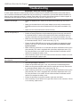
Fig. 8 EB-1 receptacle.
Electronic Gas Control
Valve
FP580
INSTA VENT FREE
JUNCTION BOX
This appliance may be fitted EB1
with
a Synetek ignition
11/18/97
module.
Installation of the remote on/off starter switch or wall
thermostat on electronic ignition units.
1. Thread the wiring through the holes on the side panels
of the appliance. Take care not to cut the wire or insulation on metal edges. Route the wire to a conveniently
located receptacle box.
2. Attach the wire to the ON/OFF switch and install the
switch into the receptacle box.
3. Connect the white wire from the wall switch or wall
thermostat to the white wire terminal from the electronic
module. Connect the black wire from the wall switch or
the red wire from the wall thermostat, to the red wire
terminal from the electronic module.
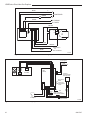
LDVR Series Direct Vent Gas Fireplace
L1
BLACK
L2
WHITE
POWER CORD
GREEN
PURPLE
PILOT SENSING
CLEAR
PILOT IGNITER
YELLOW
M
O
P
O
VALVE
CIRCUIT BOARD
BLUE
ORANGE
RED
WHITE
ON/OFF SWITCH
OR
WALL THERMOSTAT
FP1571
Fig. 9 SIT822 Valve with Synetek electronic control wiring diagram.
FP1571
SIT822
Synetek wiring
4/05 Main
Pilot
Main
Module
AF-4000
To Pilot
Flame Sensor
I
To Pilot Ignitor
S
"
White or Green
Green or White
White or Orange
Orange or White
Optional
Remote Battery
Back-Up Pack
Black
Gnd
Brown (SWI) (Connect to
Brown
(SWI) ON/OFF Switch)
Red
Black
AC Adaptor
Red
Black
Remote/Off
Switch
Continuous
Pilot ON/OFF
Switch
Extension Harness
FP1866
Fig. 10 American Flame Valve AF-4010 wiring diagram.
FP1866
wiring diagram
5/08
10
10007317
LDVR Series Direct Vent Gas Fireplace
General Venting
Your fireplace is approved to be vented either through the
side wall, or vertically through the roof.
• Only Vermont Castings Group venting components
•
•
•
specifically approved and labelled for this fireplace may
be used.
Vent terminations shall not be recessed into a wall or
siding.
Horizontal venting which incorporates the twist lock pipe
must be installed on a level plane without an inclining
or declining slope.
Horizontal venting which incorporates the use of flex
venting shall have an inclining slope from the unit of 1”
(25 mm) per 24” (610 mm).
10007317
There must not be any obstruction such as bushes,
garden sheds, fences, decks or utility buildings within 24”
(610 mm) from the front of the termination hood.
Do not locate termination hood where excessive snow or ice
build up may occur. Be sure to check vent termination area
after snow falls, and clear to prevent accidental blockage
of venting system. When using snow blowers, make sure
snow is not directed towards vent termination area.
Location of Vent Termination
It is imperative the vent termination be located observing
the minimum clearances as shown on the next page.
*Check with local codes or in absence of same with
CSAB149.1 Installation Codes (1991) for Canada or follow
the current National Fuel Gas Code, ANSI Z223.1/NFPA
54 for installations in the USA.
11
LDVR Series Direct Vent Gas Fireplace
General Venting Information - Termination Location
INSIDE
CORNER DETAIL
V
G
H
A
D
L
V
E
C
B
V
F
Ope
V
B
CFM145a
B
Fixed
Closed
V VENT TERMINATION
B
V
Operable
rable
B
V
V
Fixed
Closed
J
X
B
A
X AIR SUPPLY INLET
M
I
V
K
X
AREA WHERE TERMINAL IS NOT PERMITTED
Canadian Installations1
US Installations2
A = Clearance above grade, veranda, porch, 12”
(30cm)
12” (30cm)
CFM145a
DV Termin Location
deck, or balcony
5/01/01 Rev. 12/05/01
B = Clearance to window or door that may be 6”sta(15cm) for appliances 6” (15cm) for appliances
opened
< 10,000Btuh (3kW), 12” (30cm) < 10,000 Btuh (3kW), 9”
for appliances > 10,000 Btuh (3kW) and
(23cm) for appliances > 10,000
< 100,000 Btuh (30kW), 36” (91cm)
Btuh (3kW) and < 50,000 Btuh
for appliances > 100,000 Btuh (30kW)
(15kW), 12” (30cm) for
appliances > 50,000 Btuh (15kW)
C = Clearance to permanently closed window
12” (305mm) recommended to
12” (305mm) recommended to
prevent window condensation
prevent window condensation
D = Vertical clearance to ventilated soffit located
above the terminal within a horizontal 18” (458mm)
18” (458mm)
distance of 2’ (610mm) from the center
line of the terminal
E = Clearance to unventilated soffit
12” (305mm)
12” (305mm)
F = Clearance to outside corner see next page
see next page
G =Clearance to inside corner (see next page) see next page
see next page
H = Clearance to each inside of center line
3’ (91cm) within a height of 15’ (5m) 3’ (91cm) within a height of 15’
extended above meter/regulator assembly
above the meter/regulator assembly
(5m) above the meter/regulator
assy
I = Clearance to service regulator vent outlet
3’ (91cm)
3’ (91cm)
J = Clearance to nonmechanical air supply inlet 6” (15cm) for appliances < 10,000
6” (15cm) for appliances
to building or the combustion air inlet to any Btuh (3kW), 12” (30cm) for
< 10,000 Btuh (3kW), 9”
other appliances
appliances > 10,000 Btuh (3kW) and (23cm) for appliances > 10,000
< 100,000 Btuh (30kW), 36” (91cm)
Btuh (3kW) and < 50,000 Btuh
for appliances > 100,000 Btuh (30kW)
(15kW), 12” (30cm) for appliances > 50,000 Btuh (15kW)
K = Clearance to a mechanical air supply inlet
6’ (1.83m)
3’ (91cm) above if within 10
feet (3m) horizontally
L = Clearance above paved sidewalk or paved 7’ (2.13m)†
7’ (2.13m)†
driveway located on public property
M =Clearance under veranda, porch, deck or
12” (30cm)‡
12” (30cm)‡
balcony
N = Clearance above a roof shall extend a minimum of 24” (610mm) above the highest point when it passes through the roof surface, and any other obstruction within a horizontal distance of 18” (450mm).
1 In accordance with the current CSA-B149 Installation Codes
2 In accordance with the current ANSI Z223.1/NFPA 54 National Fuel Gas Codes
† A vent shall not terminate directly above a sidewalk or paved driveway which is located between two single family dwellings and serves both dwellings
‡ only permitted if veranda, porch, deck or balcony is fully open on a minimum 2 sides beneath the floor:
NOTE: 1. Local codes or regulations may require different clearances.
2. The special venting system used on Direct Vent Fireplaces are certified as part of the appliance, with clearances tested and approved by the listing agency.
3. Vermont Castings Group assumes no responsibility for the improper performance of the appliance when the venting system does not meet these requirements.
Fig. 11 Vent termination locations.
12
10007317
LDVR Series Direct Vent Gas Fireplace
Termination Clearances
Termination clearances for buildings with combustible and noncombustible exteriors.
Alcove Applications*
Inside Corner
Outside Corner
G=
Combustible
6" (152 mm)
G
Noncombustible
2" (51 mm)
V
F=
Combustible
6" (152 mm)
Noncombustible
2" (51 mm)
V
C
V
O
F
Balcony with perpendicular side wall
Balcony with no side wall
D
C
E
E = Min. 2” (51 mm) for
non-vinyl sidewalls
Min. 12” (305 mm) for
vinyl sidewalls
O = 8’ (2.4 m) Min.
M
M
V
V
P
Combustible &
Noncombustible
M=
Combustible &
Noncombustible
12" (305 mm)
M = 12" (305 mm)
P = 6” (152 mm)
No.
of Caps
DMin. CMax.
1
3’ (914 mm)2 x DActual
2
6’ (1.8 m)
1 x DActual
3
9’ (2.7 m)2/3 x DActual
4
12’ (3.7 m) 1/2 x DActual
DMin. = # of Termination caps x 3
CMax. = (2 / # termination caps) x DActual
584-15
*NOTE: Termination in an alcove space (spaces open only on one side and with an overhang) is permitted with the dimensions
specified for vinyl or non-vinyl siding and soffits. 1. There must be a 3’ (914 mm) minimum between termination caps. 2. All
mechanical air intakes within 10’ (1 m) of a termination cap must be a minimum of 3’ (914 mm) below the termination cap. 3. All
gravity air intakes within 3’ (914 mm) of a termination cap must be a minimum of 1’ (305 mm) below the termination cap.
Fig. 12 Termination clearances.
General Information Assembling Vent Pipes
Canadian Installations:
Venting system must be installed in accordance with the
current CSA-B149.1 installation code.
USA Installations:
* Be sure the vent is actually crushed before proceeding.
Apply a tug to be sure the vent will not slip off the collars.
Repeat process with 7” flex vent pipe. The same procedure
must be performed on the vent side.
The venting system must conform with local codes and/or the
current National Fuel Gas code ANSI Z223.1/NFPA 54.
Only venting components manufactured by Vermont
�������������
Castings Group�������������������������������������
can be used in Direct Vent systems.
Apply High Temperature
Sealant
Flex Vent Pipes
Before joining the flex vent pipe to the unit, apply a bead of
high temperature sealant* (provided) to the 4” pipe exiting
the fireplace. Secure flex vent piep in place with a hose
clamp (provided).
*Be sure the flex pipe overlaps at least 1” (25mm) onto the
collars of the fireplace and termination. If the termination
has an internal bead, be sure to overlap and secure 1”
(25mm) past the bead.
10007317
Hose Clamp
FP1471
Fig. 13 Apply high temperature sealant to 4” and 7” pipes.
13
LDVR Series Direct Vent Gas Fireplace
Twist Lock Pipes
30
29
When using Vermont
���������������������������������������������
Castings Group�����������������������
twist-lock pipe it is
not necessary to use sealant on the joints. The only areas
of the venting system that need to be sealed with high
temperature silicone sealant are the sliding joints of any
telescopic vent section used in the system.
28
27
26
25
23
To join the twist lock pipes together, simply align the beads
of the male end with the grooves of the female end, then
while bringing the pipe together, twist the pipe until the
flange on the female end contacts the external flange
on the male end. It is recommended that you secure the
joints with three (3) sheet metal screws, however this is
not mandatory with twist lock pipe.
22
21
20
19
18
17
16
15
To make it easier to assemble the joints we suggest putting
a lubricant (Vaseline or similar) on the male end of the twist
lock pipe prior to assembly.
Male End
Vertical dimension from the floor of the unit
to the center of the horizontal vent pipe
24
14
13
eg: A
12
11
10
Female End
9
8
7
eg: B
6
5
4
Screw Holes
3
TWL100
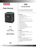
Fig. 14 Twist-lock pipe joints.
3
1. Determine the height of the center of the horizontal vent
pipe exiting through the outer wall. Using this dimension
on the Sidewall Vent Graph (Fig. 15) locate the point
intersecting with slanted graph line.
2. From the point of this intersection, draw a vertical line
to the bottom of the graph.
3. Select the indicated dimension, and position the fireplace
in accordance with same.
Example A:
If the vertical dimension from the floor of the fireplace is 11’ (3.4 m) the horizontal run to the face of the outer wall must not exceed 14’ (4.3 m).
14
Example B:
If the vertical dimension from the floor of the unit is 7’ (2.14 m), the horizontal run to the face of the outer wall must not exceed 8¹⁄₂’ (2.6 m).
5 6
7 8
9 10 11 12 13 14 15 16 17 18 19 20
Horizontal dimension from the outside face of the
wall to the center of the fireplace vent flange
How to Use the Vent Graph
TWL100
The vent chart should
be read in conjunction with the
Twist Lock
Pipe
following vent installation
instructions
to determine the
3/12/99 djt
relationship of the vertical and horizontal dimensions of
the vent system.
4
CFM102
Sidewall vent graph showing the relationship between vertical
DV Graphic
horizontal dimensions
for a Direct Vent flue system.
and
9/28/00 sta
Fig. 15 Sidewall venting graph. (Dimensions in feet)
Rear Wall Venting Applications
When installed as a rear vent unit this appliance may be
vented directly to a termination located on the rear wall
behind the appliance.
• Only Vermont
������������������������������������������
Castings Group��������������������
venting components
•
•
•
are approved to be used in these applications. (Refer
to “Venting Components” listed for different installation
requirements)
The maximum horizontal distance between the rear of
the appliance (or end of the transition elbow in a corner
application) and the outside face of the rear wall is 20”
(508mm). (Fig. 16)
Only one 45° elbow is allowed in these installations.
Minimum clearances between vent pipe and combustible materials are as follows:
Top - 2” (51 mm)
Sides - 1” (25 mm)
Bottom - 1” (25 mm)
10007317
LDVR Series Direct Vent Gas Fireplace
Vent Opening for Combustible Wall
9³⁄₈”
(240mm)
20"
(508mm)
Framing
Detail
10³⁄₈”
(264mm)
Top View
Straight Venting
Fireplace Hearth
DVR584-600
20"
20"
Rear vent no elbows
(508mm)
(508mm)
Max.
Max.
2/99
djt
Opening for Noncombustible Wall
7¹⁄₂”
(190mm)
45°
45°
Max. Length
12” (305mm)
Adjustable
Zero Clearance
Sleeve
Top View
REAR VENT-TOP VIEW
Rear Vent Corner Installation
#8 Screws
(2)
Fig. 16 Rear vent applications, one 45° elbow.
FP836
Rear Wall Installation
Rear Vent-Top View
11/21/98
Twist Lock
Pipe
NOTE: When using flex vent, the opening will have to be
measured according to the 1/2” (13 mm) rise in 12” (305
mm) vertical run.
Combustible Walls (Fig. 17): Cut a 10³⁄₈”H x 9³⁄₈” W (264
x 240 mm) hole through the exterior wall and frame as
shown.
Noncombustible Walls (Fig. 17): Hole opening must be
7¹⁄₂” (190 mm) in diameter.
STEP 2
Measure wall thickness and cut zero clearance sleeve
parts to proper length (MAXIMUM 12”/305 mm). Assemble
sleeve and attach to firestop with #8 sheet metal screws
(supplied). (Fig. 18)
#8 Screws (2)
VO584-100
Vent Opening
2/99 djt
#8
Screws
(2)
Firestop
STEP 1
Locate vent opening on the wall. To locate hole center
consult with appropriate fireplace dimensions, Page 4.
Frame as shown below.
VO584-100
Fig. 17 Locate vent opening on wall.
Adjustable Zero Clearance Sleeve
ZCS101
Fig. 18 Adjustable ZCS101
zero clearance sleeve.
STEP 3
Zero Clearance Sleeve
3/11/99 djt
Measure from the fireplace collar or elbow face to face
of outside wall (add 2” for vent pipe overlap). Mark pipes
and cut to length. It is very important that the two pipes
are flush with the outside wall once the fireplace is in its
final location. (Fig. 19)
STEP 4
Slip 4” and 7” pipes onto respective flue collars. Make sure
to fix to the fireplace collar the 4” pipe with three (3) screws
before fixing the 7” pipe on the 7” collar. Both pipes must
be on a level plane. (Fig 20)
STEP 5
Guide the vent termination 4” collar into the 4” pipe then
the 7” collar into the 7” pipe. Do not force the venting into
position. If the pipes do not line up with the termination
collars, disassemble pipes and reattach to the fireplace
collar. (Fig. 21)
STEP 6
Secure fireplace to floor through floor holes and adjustable frame drywall strip (nailing flange) to frame. (Refer to
Framing & Finishing Section).
10007317
15
LDVR Series Direct Vent Gas Fireplace
Zero
Clearance
Sleeve
Termination
Flex Section
Appliance Collars
Firestop
CFM133
Fig. 19 Firestop and zero clearance sleeve in place.
CFM133
DVR Series Typical corner install
Finished Wall 2/26/01 sta
Vent Termination
FP1473
Fig. 21 Grasp the vent pipe close to the collar and bend to 45°
angle. Do not exceed 45°.
Rise
FP1473
corner flex install
4/04 djt
FP1472
Fig. 22 There must be a 1/2” rise per foot length.
FP1005
Fig. 20 Side view of final unit location.
FP1005
Rear Wall Vent
Installations Side View Vent Termination
Flex1/25/00
Vent Pipe
djt
Follow Steps 1 and 2 on Page 15.
Step 3
Install the 4” (102 mm) flex vent pipe to the appliance collars described in “General Information Assembling Vent
Pipes”, Page 11. If the installation requires a 45° angle,
grasp the vent pipe close to the appliance collar and bend
to 45°. DO NOT exceed 45°. (Fig. 21)
Install the 7” vent pipe in the same manner as Step 2.
NOTE: There must be a 1” (25 mm) rise in a 24” (610mm)
length of flex vent.
Step 4
Assemble the flex vent to the collars on the termination as
you did on the appliance.
Vertical Sidewall Applications
Since it is very important that the venting system maintain its balance between the combustion air intake and the flue gas exhaust, certain
limitations asFP1472
to vent configurations apply and
must be strictly
adhered
rise in
length to.
4/04shows
djt
The Vent Graph
the relationship between
vertical and horizontal side wall venting and will help to
determine the various dimensions allowable.
Minimum clearance between vent pipes and combustible materials is 1”(25 mm) on top, bottom
and sides unless otherwise noted.
When vent termination exits through foundations
less than 20” below siding outcrop, the vent pipe
must flush up with the siding. It is always best to locate
the fireplace in such a way that minimizes the number of
offsets and horizontal vent length.
The horizontal vent run refers to the total length of vent
pipe from the flue collar of the fireplace to the face of the
outer wall.
Horizontal plane means no vertical rise exists on this portion of the vent assembly.
16
10007317
LDVR Series Direct Vent Gas Fireplace
• The maximum horizontal vent run is 20 ft. (6.1 m) when
7 ft.
(2134 mm)
the vertical vent rise is 7¹⁄₂ ft. (2.3 m). (Fig. 23)
• The maximum number of 90° elbows per side wall
10 ft.
(3048 mm)
installation is three (3).
Vertical Dimension
7¹⁄₂’ Minimum When
Horizontal Run is
20’
Maximum
20 ft. (6.1m)
12"
(305mm)
48"
(1.2m)
A + B = 17 ft. (Max.)
15 ft.
(4572mm)
7 ft. 6 in.
(2286 mm)
CFM147
7.5'
(2.3m)
Fig. 25 Maximum vent run with elbows.
7TDVRT90
Elbow
V584-201
• The maximum number
ofRun
elbow degrees in a system is
Horizontal
CFM141
270°. (Fig. 26)
Fig. 23 Maximum number of 90° elbows is three (3).
CFM141
• If a 90° elbow is used2/2/01
in thestahorizontal vent run (level
height maintained) the maximum horizontal vent length
is reduced by 36” (914 mm). (Fig. 24) This does not
apply if the 90° elbows are used to increase or redirect
a vertical rise. (Fig. 25)
2/99 djt
Example:
Elbow 1 = 90˚
4
Elbow 2 = 45˚
Elbow 3 = 45˚
Elbow 4 = 90˚
Total angular variation = 270˚
o
1 + 2 + 3 + 4 = 270
Maximum
3' (914mm)
1
CFM142
Fig. 24 Maximum horizontal vent run.
•
•
Example: According to CFM142
the chart the maximum horizonVenting
tal vent length in a system
with a 7.5’ (2.3 m) vertical
2/2/01 sta
rise is 20’ (6 m) and if a 90° elbow is required in the
horizontal vent it must be reduced to 17’ (5.2 m). In
Figure 25 Dimension A plus B must not be greater than
17’ (5.2 m).
The maximum number of 45° elbows permitted per side
wall installation is six (6). These elbows can be installed
in either the vertical or horizontal run.
For each 45° elbow installed in the horizontal run, the
length of the horizontal run MUST be reduced by 18”
(45cm). This does not apply if the 45° elbows are installed on the vertical part of the vent system.
10007317
2
3
CFM132
7TDVRT90
Elbow
90° Elbow = 3 ft.
Fig. 26 Maximum number CFM132
of elbows.
Insert Rear Vent Sidewall
2/26/01 sta
• IMPORTANT• Minimum clearance between vent
pipes and combustible materials is one (1”) inch
(25 mm) on bottom, sides and top.
Twist Lock Vent Starter Kit 7TDVSK, plus Transition
Elbow 7TDVRT90 must be used in Vertical Sidewall
installations. The 4” pipe must be centered inside the
7” pipe coming off the transition elbow.
Canadian & USA Installations:
The venting system must conform with local codes, or in
the absence of local codes, with National Fuel Gas Code,
ANSI Z223.1/NFPA 54 - latest edition, or CSA B149.1
Installation Code.
Only Vermont Castings Group venting components specifically approved and labelled for this fireplace may be
used.
17
LDVR Series Direct Vent Gas Fireplace
Vertical Sidewall Installation
STEP 1
Locate vent opening on the wall. It may be necessary
to first position the fireplace and measure to obtain hole
location. Depending on whether the wall is combustible or
noncombustible, cut opening to size. (Fig. 27)
Adjustable Zero Clearance Sleeve
#8 Screws (2)
#8 Screws (2)
For combustible walls first frame in opening.
Combustible Walls (Fig. 27): Cut a 9³⁄₈”H x 9³⁄₈” W (240 x
240 mm) hole through the exterior wall and frame.
Noncombustible Walls (Fig. 27): Hole opening must be
7.5” (190 mm) in diameter.
Vent Opening for Combustible Wall
Maximum Length
12” (305mm)
Wall Exterior
#8 Screws (2)
Adjustable Zero
Clearance
Sleeve
Firestop
Zero Clearance
Sleeve Flush with
Wall Exterior
Wood Framing
Firestop
Vent Pipe
9³⁄₈”
(240mm)
Drywall
CFM135
Fig. 28 Locate vent opening on wall.
9³⁄₈”
(240mm)
CFM135
Zero Clearance Sleeve
2/26/01 sta
Ensure Pipes are
Concentric
Framing Detail
8
Fireplace Hearth
Opening for Noncombustible Wall
7¹⁄₂”
(190mm)
Ç/6,/ä
VO584-100
Fig. 27 Locate vent opening on wall.
Fig. 29 Apply sealant to inner and outer pipe.
STEP 2
Measure wall thickness and cut adjustable zero clearance
sleeve parts to proper length (MAXIMUM 12”/305 mm). (Fig.
VO584-100
28) Adjust sleeve to minimum
(9³⁄₈” x 9³⁄₈” and attach to firestop
with #8 sheet metal screws
(supplied).
Assemble sleeve and
Vent
Opening
attach to firestop with #82/99
sheet metal
screws
(supplied). Install
djt
firestop assembly.
Zero clearance sleeve is only required for
combustible walls.
STEP 3
Attach the appropriate venting component(s) to the inner and outer flue collars of the fireplace using three (3)
screws. (Fig. 29) Follow with the installation of the inner
and outer elbow. Again secure joints with three (3) sheet
metal screws.
18
CFM143
STEP 4
CFM143
2/2/01 sta
Measure the horizontal length requirement including a 2”
(51 mm) overlap, i.e. from the elbow to the outside wall
finish plus 2”, or the distance required if installing a second
90° elbow. (Fig. 30)
STEP 5
Use appropriate length of pipe section - telescopic or fixed
- and install the horizontal vent sections. The 20” (508
mm) section of pipe which goes through the wall is packaged with the 7TDVSK starter kit, and can be cut to suit if
necessary. (Fig. 31)
Sealing vent pipe and firestop gaps with high
temperature sealant will restrict cold air being
drawn in around fireplace.
10007317
LDVR Series Direct Vent Gas Fireplace
X
X
X
Always install horizontal venting on a
level plane.
CFM138
CFM136
Fig. 30 Measure horizontal length including 2” overlap.
CFM136
X length
Rear Vent horizontal
High
2/26/01 sta
Temperature Sealant
Fig. 32 Horizontal length requirement.
CFM138
Below Grade
4", 7" collarInstallations
2/26/01 sta
When it is not possible to meet the required vent terminal
clearances of 12” (305 mm) above grade level a snorkel
vent kit #7TDVSNORK is required. It allows installation
depth of down to 7” (178 mm) below grade level. The 7”
is measured from the center of the horizontal vent pipe as
it penetrates through the wall.
If venting system is installed below ground,
we recommend a window well with adequate
and proper drainage.
Ensure sidewall venting clearances are observed.
CFM137
Fig. 31 Apply high temperature sealant.
STEP 6
CFM137
Rear Vent length
2/26/01 sta
termination’s
4” (102
Guide the vent
mm) and 7” (178 mm)
collars into their respective vent pipes. Double check that
the vent pipes overlap the collars by 2” (51 mm). Secure
the termination to the wall with screws provided and caulk
around the wall plate to weatherproof. (Fig. 32)
STEP 7
Support the horizontal pipes every 36” (914 mm) with
metal pipe straps. Make sure that the horizontal vent pipe
is installed on a level horizontal plane.
STEP 8
Re-check the fireplace to make sure that it is levelled,
properly positioned, and nailed or screwed to the floor.
If applied, the fireplaces adjustable frame drywall strips
(nailing flanges) should be fastened. Refer to “Framing &
Finishing”.
10007317
The maximum horizontal run with 24” vertical
rise is 36” (914 mm) from the back of the
fireplace to the face of the exterior wall. See
vent graph (Page 14) for extended horizontal
run if the vertical rise exceeds 24” (610 mm).
1. Establish vent hole through the wall. (Fig. 27)
2. Remove soil to a depth of approximately 16” (406mm)
below base of snorkel. Install window well (not supplied).
Refill hole with 12” (305 mm) of coarse gravel leaving a
clearance of approximately 4” (102 mm) below snorkel.
(Fig. 33)
3. Install vent system. See Page 15, Steps 2 through 5.
4. Ensure a watertight seal is made around the vent pipe
coming through the wall.
5. Apply high temperature sealant caulking (supplied)
around the 4” and 7” snorkel collars.
6. Slide into the vent pipe and secure to the wall.
7. Level the soil to maintain a 4” (102 mm) clearance below
snorkel. (Fig. 33)
19
LDVR Series Direct Vent Gas Fireplace
Zero Clearance
Sleeve
(if required)
7TDVSNORK
(Snorkel)
Firestop
4” (102mm)
Clearance
Min.
7” Pipe
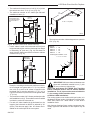
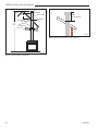
Vertical Through-the-Roof Applications
This Gas Fireplace has been approved for:
1. Vertical installations up to 40’ (12 m) in height. Up to
10’ (3 m) horizontal vent run can be installed within the
vent system using a maximum of three 90° elbows.
Window
Well
24" (610mm)
Minimum*
Gravel
Drain
Foundation Wall
*A minimum of 24” (608mm) vertical pipe must be installed when
using 7TDVSNORK Kit.
Minimum
8’ (2.4 m) /
Maximum
40’ (12 m) Vertical
Rise
Maximum
10’
(3 m)
Pipe Straps Every 3’
(914 mm)
BG400
Fig. 33 Below grade installation.
Do not back fill around snorkel. A clearance
of at least 4” (102mm) must be maintained
BG400
between the snorkel and the soil.
Below grade installation
2/10/99 djt
10/19/99 added standoffs
Snorkel
Foundation Recess
Wall Screws
Recess Brackets
Watertight Seal
Around Pipe
Sheet Metal
Screws
BG401
Fig. 34 Snorkel installation, recessed foundation.
If the foundation isBG401
recessed, use recess brackets (not
supplied) for securing
lower portion of the snorkel. Fasten
Snorkel
brackets to wall first, then secure to snorkel with self drilling
2/10/99 djt
#8 x 1/2 sheet metal screws. It will be necessary to extend
vent pipes out as far as protruding wall face. (Fig. 34)
20
CFM148
Fig. 35 Support straps forCFM148
horizontal runs.
This Gas Fireplace has been approved for:
1. Vertical installations up to 40’ (12 m) in height. Up to
10’ (3 m) horizontal vent run can be installed within the
vent system using a maximum of three 90° elbows.
2. Up to two 45° elbows may be used within the horizontal
run. For each 45° elbow used on the horizontal level
the maximum horizontal length must be reduced by 18”
(457 mm).
Example: Maximum horizontal length
0 x 45° elbows = 10’ (3 m)
1 x 45° elbows = 8¹⁄₂’ (2.6 m)
2 x 45° elbows = 7’ (2.1 m)
3. A minimum of an 8’ vertical rise.
4. Two sets of 45° elbows offsets within these vertical
installations. From 0 to a maximum of 8’ (2.4 m) of vent
pipe can be used between elbows. (Fig. 36)
5. 7DVCS must be used to support offsets. (Fig. 36) This
application will require that you first determine the roof
pitch and use the appropriate 7DVSKV (A, B or F).
(Refer to Venting Components List, Page 23)
10007317
LDVR Series Direct Vent Gas Fireplace
Attic Insulation
Shield
Max.
8’
(2.4m)
45°
40’
(12m)
Max.
8’
(2.4m)
Joist
Typical Ceiling Support
Application
Ceiling Installation
45°
11"
11"
Upper Floor
Joist
Typical Roof
Support Application
Typical Offset Installation
Firestop Spacer
Nails (4)
FP1021
Fig. 36 Typical vertical roof applications.
FP1021
Vertical Through-the-Roof
Typical vertical Installation
through the roof
1. Locate your fireplace.
application
2. Plumb to center of 3/26/00
the (4”) flue
djt collar from ceiling above
and mark position.
3. Cut opening equal to 9³⁄₈” x 9³⁄₈” (240 x 240mm).
4. Proceed to plumb for additional openings through the
roof. In all cases, the opening must provide a minimum
of 1 inch clearance to the vent pipe, i.e., the hole must
be at least 9³⁄₈” x 9³⁄₈” (240 x 240 mm).
5. Place fireplace into position.
6. Place firestop(s) #7DVFS or Attic Insulation Shield
#7DVAIS into position and secure. (Fig. 37)
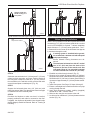
7. Install roof support (Fig. 38 & 39) and roof flashing
making sure upper flange is below the shingles. (Fig.
38)
8. Install appropriate pipe sections until the venting is above
the flashing. (Fig. 38)
9. Install storm collar and seal around the pipe.
10. Add additional vent lengths for proper height. (Fig
40)
11. Install vertical vent termination.
CFM100
Fig. 37 Place firestop spacer(s) and secure.
CFM100
If there is room
above ceiling level, firestop
Firestop-Vertical
spacer must
be installed on both the bottom
09/20/00
and the top side of the ceiling joists. If an attic
is above ceiling level a 7DVAIS (Attic Insulation
Shield) must be installed. (Fig. 37)
The enlarged ends of the vent section always
face downward. (Fig. 38)
3 #5 Sheet Metal
Screws per Joint
Sealant
Storm Collar
TWL101a
Fig. 38 Roof flashing.
TWL101a
Twist Lock Pipe
2/8/99 djt
10007317
21
LDVR Series Direct Vent Gas Fireplace
Vent
Termination
Roof
Storm Collar
2’ Min.
Roof Flashing
Roof Support
Attic Insulation
40’
Shield
(12 m)
Attic
Insulation
Joists
Min.
2' (610 mm)
Joists
FP1185
Fig. 40 Minimum termination to roof clearance.
FP1022
Fig. 39 Typical straight-up installation.
FP1022
Typical Straight Up Installation
1/26/00 djt
22
10007317
LDVR Series Direct Vent Gas Fireplace
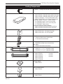
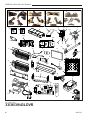
Venting Components
7TDVRVT - Through the wall Rear Vent Termination
584A
venting components
rear vent term
4/6/99 djt
584B
Vent components
Starter Kit
2/25/99 djt
584C
Vent components
584D
45 degree
elbow
Vent
Components
2/25/99
90
degree djt
elbow
584E
10/20/99djttwistlock
2/25/99
Venting Components
10/20/99
twist lock
Telescope
vent
584F
2/25/99 djt
Venting Components
10/20/99 twist lock
Pipe sections
2/25/99 djt
10/20/99 twist lock
584G
Venting Components
Firestop spacer
2/25/99 djt
10007317
584H
Venting components
attic insulation shield
2/25/99 djt
584I
vent components
offset support
2/25/99 djt
Starter Kit Model 7TDVSK - Sidewall Venting (Twist Lock Pipe)
Model 7FDVSK - Sidewall Venting (Flex Vent Pipe)
Models 7TDVTK/TV - Hot Touch Termination Kits
Model 7TDVTVTK/TV - Cool Touch Termination Kit
Starter Kit - Model 7TDVSKV - Vertical Venting
for 7TDVSKV-A order 1/12 to 6/12 roof pitch
for 7TDVSKV-B order 7/12 to 12/12 roof pitch
for 7TDVSKV-F order flat roof
Starter Kit for Below Grade Installation
Model 7TDVSKS -Snorkel Kit (Twist Lock Pipe)
Model 7FDVSKS -Snorkel Kit (Flex Vent Pipe)
Starter Pipe
Model 7TDVP 20/8 - 24” Starter Pipe Bulk
Model 7FDVP 30/8 - 30” Flex Pipe Bulk
45o Elbow
7TDV45 for Rear Vent to Vertical Vent
or Vertical/Horizontal Offsets
90o Transition Elbow
7TDVRT90 for Rear Vent to Vertical Vent
90° Elbow
7TDV90 Vertical/Horizontal Offset
Telescopic vent sections
7TDVP1117 -11” to 17” adjustable length
7TDVP3567 -35” to 67” adjustable length
Pipe sections for vertical or horizontal venting
Model 7TDVP8”
-
4 per box
Model 7TDVP12”
-
4 per box
Model 7TDVP24”
-
4 per box
Model 7TDVP36”
Model 7TDVP48”
Firestop Spacer
Model 7DVFS
Attic Insulation Shield
Model 7DVAIS
Vertical/Horizontal Combination Offset Support
Model 7DVCS
23
LDVR Series Direct Vent Gas Fireplace
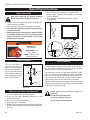
Operating Instructions
Glass Information
Only glass approved by Vermont Castings
Group should be used on this fireplace.
6. Tilt the window frame assembly out slightly at the bottom, lift the window frame assembly up and away
from the fireplace.
7. To replace the window frame assembly reverse the procedure.
• The use of any non-approved replacement glass will
void all product warranties.
• Care must be taken to avoid breakage of the glass.
• Do not operate appliance with glass front removed,
cracked or broken.
• Replacement glass (complete with frame window)
is available through your Vermont Castings Group
dealer and should only be installed by a licensed
qualified service person.
Lower Clamps
7!2.).'
(/4',!337),,
#!53%"52.3
$/./44/5#(',!33
5.4),#//,%$
.%6%2!,,/7#(),$2%.
4/4/5#(',!33
Window
Frame
Assembly
Window
Frame
Assembly
Pull Clamp
Push Hook
Clamp
Handle
FP1228
Fig. 42 Window frame assembly removal.
Louvre Removal
The top louvre panel is
removed by lifting the
panel vertically and pulling
it away from the appliance.
(Fig. 41) The lower access
door is hinged along the
bottom edge and is folded
down to allow access.
Glass Cleaning
2.
Louvre
1.
Glass Panel
FP1227
Fig. 41 Remove top louvre
assembly.
FP1227
Window Frame Assembly Removal
Louvre removal
1. Turn the fireplace OFF (including11/02
the pilot)
2. If the unit has been operating allow time for the
components to cool.
3. Remove the top louvre assembly.
4. Open the lower louvre panel.
5. Release the two clamps securing the lower edge of the
window frame assembly by pulling down on the handles.
(Fig. 42)
24
It is necessary to periodically clean glass. During startup condensation, which
is normal, forms on the inside of
FP1228
the glass. This condensation
causes
lint, dust and other
remove glass
frame
airborne particles to cling
to
glass
surface.
11/02
Also initial paint curing may deposit a slight film on the
glass. It is therefore recommended the glass be cleaned
two or three times with a non-ammonia based household
cleaner and warm water (We recommend gas fireplace
glass cleaner) within the first few weeks of operation.
After the initial cleaning process the glass should be cleaned
two or three times during each operating season depending
on the environment in the house.
Clean glass after first two weeks of
operation.
Do not clean glass when hot.
Do not use abrasive cleaners.
Do not strike or slam the glass.
10007317
LDVR Series Direct Vent Gas Fireplace
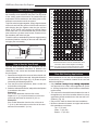
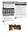
Installation of Logs, Lava Rock & Ember Material
The logs are fragile and should be handled
with care. Keep the packaging material out
of the reach of children and dispose of the
material in a safe manner.
The individual logs can be easily identified
by the numbers cast on the underside of
each log.
Log Identification Chart
Location
33LDVR 36LDVR 39LDVR
Front Left
A43
B160
BC15
Front Right
--
B159
BC16
Front Center
--
B161
B138
Rear
--
B158
BC14
Rear Left
A41
--
--
Rear Right
A42
--
--
Top Center
A44
--
--
43LDVR
BD16
BD17
B138
BD15
--BD18
Log Installation
1. Remove the top louvre assembly.
2. Open the bottom louvre.
3. Remove the window frame assembly.
4. Remove log box from inside firebox.
5. Unpack the logs from packaging and remove each log
from its wrapping material. Set aside the ember and the
lava rock bags.
As with all plastic bags - these are not toys
and should be kept away from children and
infants.
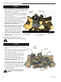
Rear Left
(A41)
Top Center
(A44)
33LDVR
1. Place rear log left (A41) on rear bracket (ensure the
notch on the left end locates against the bend up on
the left side of rear bracket.)
2. Place rear log right (A42) on rear bracket (ensure the
notch on the right end locates against the bend up on
the right side of rear bracket) and just rest the cut out
from front log onto the front support.
3. Place front log left (A43). Use the log’s bottom hole to
locate it onto rear log left (A41) and just rest bottom cut
out log onto the front support.
4. Place top log center (A44). Use the log’s bottom hole
to locate it onto the knob on the rear log right (A42) and
the top log center rest onto rear log left.
5. Place ember material on top of burner. Scatter the
ember material over the tiles on the front area of the
burner housing. (Fig. 50) Do not pack the ember material. Separate it when unpacked and keep it in a fluffy
and loose condition for a more realistic ember effect.
6. Scatter the lava rock material around the firebox
base.
Do not place any of the lava rock material on
the burner housing assembly.
Rear Right
(A42)
Figure 43
33LDVR
LG382
Front Left
(A43)
10007317
25
LDVR Series Direct Vent Gas Fireplace
36LDVR
1. Place rear log (B158) on rear bracket (ensure log is
seated properly to the bracket and located to the two
pins), so it will not move from side to side and is
Figure 44
firmly positioned on the bracket.
36LDVR
2. Place front left log (B160). Use the log’s bottom
hole to locate it onto the front support and just rest
on top of the rear log.
3. Place front right log (B159). Use the log’s bottom
hole to locate it onto the front support and the
top hole to the knob onto the rear log.
4. Place front center log (B161) on top of the two
small shelves at the front log support and
between the left and right logs.
5. Place ember material on top of burner.
Scatter the ember material over the tiles
on the front area of the burner housing. (Fig. 50) Do not pack the ember
material. Separate it when unpacked
and keep it in a fluffy and loose condition for a more realistic ember effect.
Front Left
6. Scatter the lava rock material around
(B160)
LG481
the firebox base.
Rear
(B158)
Front Center
(B161 )
Front Right
(B159)
Do not place any of the lava rock material on the burner housing assembly.
39LDVR
1. Place rear log (BC14) on rear bracket (ensure log is
centered and seated properly to the log support).
Front Left
2. Place front left log (BC15). Use log’s bottom (BC15)
hole to locate it onto the front support and just
rest on top of the rear log.
3. Place front right log (BC16). Use log’s bottom
hole to locate it onto the front support and the
top hole to the knob on the rear log.
4. Place front center log (B138) on top of the two
small shelves at the front log support, and between the left and right logs.
5. Place ember material on top of burner.
Scatter the ember material over the tiles on
the front area of the burner housing. (Fig.
50) Separate it when unpacked and keep
it in a fluffy and loose condition for a more
realistic ember effect.
Do not place any of the lava rock
material on the burner housing assembly.
,'
,$6LOGS
Figure 45
39LDVR
Front Right
(BC16)
Rear
(BC14)
LG414
Front Center
(B138)
26
10007317
,'
,$6,OGS
LDVR Series Direct Vent Gas Fireplace
43LDVR
1. Place rear log (BD15) on rear bracket (ensure log is
Figure 46
centered and seated properly to the log support).
43LDVR
2. Place front left log (BD16). Use log’s bottom notch to
Top Center
(BBD18)
locate it onto the front support and just rest on top of Rear
the burner housing tile.
(BD15)
3. Place front right log (BD17). Use log’s bottom
notch to locate it onto the front support and
just rest on top of the burner housing.
Front
Left
4. Place ember material on top of burner.
(BD16)
5. Scatter the ember material over the tiles on
the front area of the burner housing. (Fig. 46)
Do not pack the ember material. Separate it
when unpacked and keep it in a fluffy and
loose condition for a more realistic ember effect.
6. Place front center log (B138) on top of the
two small shelves at the front log support,
and between the left and right logs.
7. Place top center log (BD18) on top of the rear log using
Lava Rock
the hole locator under the log and on top of front right
Front Center
log.
(B138)
8. Scatter lava rock material round the firebox base.
Do not place any of the lava rock material on
the burner housing assembly.
Flame & Temperature Adjustment
RN/RP & EN/EP Models
For units equipped with “HI/LO” valves the flame adjustment
is accomplished by rotating the “HI/LO” adjustment knob
located near the center of the gas control valve. (Fig.
47)
HI
LO
Turn
counterclockwise
to increase
flame height
SIT 820 Valve
Turn clockwise
to decrease
flame height
Front Right
(BD17)
LG434
Lava
Rock
Ember Material
,'
Flame
Characteristics
,$6LOGS
It is important to periodically
perform a visual check of the
pilot and burner flames. Compare them to the illustrations.
(Figs. 48 & 49)
If the flame patterns appear abnormal contact a qualified
service provider for service and adjustment.
SIT RN/RP
Fig. 47 Flame adjustment knob for SIT valve.
FP390
FLAME ADJUSTMENT KNOB
11/21/96
SIT EN/EP, IN/IP
FP1541
Fig. 48 Correct pilot flame appearance.
10007317
27
LDVR Series Direct Vent Gas Fireplace
33LDVR
LG384
Glowing Embers
36LDVR
LG482
Glowing Embers
LG384
33LDV log flames
1/05
39LDVR
,'
,$6LOGFLAMES
LG415
Glowing Embers
Figure 49
,'
,$6,OGFLAMES
43LDVR
LG435
Glowing Embers
28
10007317
,'
LDVR Series Direct Vent Gas Fireplace
Lighting and Operating Instructions
For Fireplaces Equipped with the SIT820 Valve
FOR YOUR SAFETY READ BEFORE LIGHTING
WARNING:If you do not follow these instructions exactly, a fire or explosion
may result causing property damage, personal injury or loss of life.
A. This heater has a pilot which must be lit manually. When
lighting the pilot follow these instructions exactly.
B. BEFORE LIGHTING smell all around the heater area
for gas. Be sure to smell next to the floor because
some gas is heavier than air and will settle on the
floor.
WHAT TO DO IF YOU SMELL GAS
• Do not try to light any fireplace
• Do not touch any electric switch
• Do not use any phone in your building
• Immediately call your gas supplier from a
neighbor’s phone.
Follow the gas supplier’s instructions.
• If you cannot reach your gas supplier, call the Fire
Department
C.Use only your hand to push in or turn the gas control
knob. Never use tools. If the knob will not push in or
turn by hand, do not try to repair it, call a qualified
service technician. Applying force or any attempted
repair may result in a fire or explosion.
D.Do not use this fireplace if any part has been under
water. Immediately call a qualified service technician
to inspect the heater and to replace any part of the
control system and any gas control which has been
under water.
Lighting Instructions
1. STOP! Read the safety information above.
2. Turn off all electrical power to the fireplace.
3. Turn the On/Off switch to “OFF” position.
4. Open control access panel.
5. Push in gas control knob slightly and turn clockwise
to “OFF”.
3/8" - 1/2"
"
OFF
"
O FF
3 4 5
OFF
/
"
*
"
1 2
Pilot
PILOT
10. Push the control knob all the way in and hold. Immediately light the pilot by repeatedly depressing the
piezo spark ignitor until a flame appears. Continue
to hold the control knob in for about one (1) minute
after the pilot is lit. Release knob and it will pop back
up. Pilot should remain lit. If it goes out, repeat steps
5 through 8.
SIT NOVA
Honeywell
6. Wait five (5) minutes to clear out any gas. Then smell
for gas, including near the floor. If you smell gas,
STOP! Follow “B” in the safety information above. If
you do not smell
gas, go to the next step.
FP1067
lighting instruction
7. Remove glass
door before lighting pilot. (See Glass
knobs
Frame Removal
3/9/01section).
djt
8. Visibly locate pilot by the main burner.
9. Turn knob on gas control counterclockwise
to
“PILOT”.
• If knob does not pop up when released, stop and
immediately call your service technician or gas
supplier.
• If after several tries, the pilot will FP1068
not stay lit, turn
the gas control knob to “OFF” and call
yourinstructions
service
Lighting
technician or gas supplier.
Pilots
11. Replace glass door.
12. Turn gas control knob to “ON” position.
13. Turn the On/Off switch to “ON” position or set thermostat to desired setting.
14. Turn on all electrical power to the fireplace.
To Turn Off Gas To Heater
1. Turn the On/Off switch to Off position.
2. Turn off all electric power to the fireplace if service
is to be performed.
3. Open control access panel.
10007317
4. Push in gas control knob slightly and turn clockwise
to “OFF”. Do not force.
5. Close control access panel.
29
LDVR Series Direct Vent Gas Fireplace
Lighting and Operating Instructions
For Fireplaces equipped with SIT822 Gas Valve (EN or EP)
Warning
If you do not follow these instructions exactly, a fire or explosion
may result causing property damage, personal injury and loss of life.
For your safety read the following warnings
before lighting the appliance
A. This fireplace is equipped with an ignition device which
automatically lights the pilot. DO NOT try to light the
pilot by hand.
B.BEFORE OPERATING, smell all around the appliance area for gas. Be sure to smell next to the floor because some gas is heavier than the air and will settle on the floor.
What to do if you smell gas
• Do not try to light any appliance
• Do not operate any electrical switch.
• Do not use any phone in your building.
• Immediately call your gas supplier from a neighbor’s phone.
Follow the gas suppliers instructions.
• If you cannot contact your gas supplier call the
Fire Department
C.Use only your hand to push in or turn the gas control
knob. Never use tools. If the knob will not push in or turn
by hand do not try to repair it, call a qualified service
technician. Force or attempting repair may result in a
fire or explosion.
D.Do not use this appliance if any part has been under
water. Immediately call a qualified service technician
to inspect the appliance and replace any part of the
control system and any gas control that has been under
water.
Lighting Instructions
1. STOP! Read the safety information above before
continuing.
2. Turn off all electrical power to the appliance.
3. This appliance is equipped with an ignition device which
automatically lights the pilot. DO NOT try to light the
pilot by hand.
4. Access the gas control by lowering the lower access
door (louvre assembly).
5. Turn the remote switch, if used, OFF. Turn the wireless
remote, if used, OFF.
6. Wait five (5) minutes to clear out any gas. Then smell
for gas, including near the floor. If you smell gas STOP.
Follow instructions B in the safety warnings above. If
you do not smell gas go onto the next step.
7. Close the access door.
8. Turn ON all electrical power to the appliance.
9. Turn remote switch or wireless remote to “ON”.
10. If the appliance will not operate, follow the instructions
TURNING OFF THE GAS TO THE APPLIANCEand
call your service technician or gas supplier.
LO
HI
Turning Off the Gas to the Appliance
1. Turn the remote switch to the “OFF” position.
2. Turn OFF all electrical power to the fireplace if service is required.
3Open the lower access panel.
4. Turn the shut-off valve on the flexible gas line to the “OFF” position.
30
1/2” Gas Supply
1/2” NPT x 1/2” Flare Shut-Off
Valve
3/8” Flex Line
(From Valve)
Valve in the on position
FP297A
10007317
FP297A
INSTA VENT FREE
UVHB26 GAS SUPPLY
7/1/98
LDVR Series Direct Vent Gas Fireplace
Lighting & Operating Instructions
For Fireplaces equipped with AF4000 Gas Valve
Warning
If you do not follow these instructions exactly, a fire or explosion may result,
causing property damage, personal injury and loss of life.
For Your Safety, Read the Following Warnings
before Lighting the Appliance
A. This fireplace is equipped with an ignition device which
• Do not use any phone in your building.
automatically lights the pilot. DO NOT try to light the
• Immediately call your gas supplier from a neighbor’s
pilot by hand.
B. BEFORE OPERATING, smell all around the appliance
area for gas. Be sure to smell next to the floor because
some gas is heavier than the air and will settle on the
floor.
What to do if you smell gas
• Do not try to light any appliance.
• Do not operate any electrical switch.
phone. Follow the gas suppliers instructions.
• If you cannot contact your gas supplier call the
Fire Department
C.Do not use this appliance if any part has been under
water. Immediately call a qualified service technician
to inspect the appliance and replace any part of the
control system and any gas control that has been under
water.
Lighting Instructions
“I” Connection
Connect to
Module
Flame Control
Knob
"
1. STOP! Read the safety information above before
continuing.
Spark to Pilot
Pilot Assembly
2. This appliance is equipped with an ignition device
which automatically lights the pilot. DO NOT try to
“S” Connection
light the pilot by hand.
Connect to Module
3. Turn the remote switch, if used, OFF. Turn the
wireless remote, if used, OFF.
Pilot Adjustment
Screw
Main Valve Internal
Pilot Gas Con4. Wait five (5) minutes to clear out any gas. Then
Solenoid Connecnection
smell for gas, including near the floor. If you
tion
Green
&
White
Side or Back
Inlet Pressure
Wires
smell gas, STOP. Follow instruction B in the
Tap
safety warnings above. If you do not smell
gas, go on to the next step.
5. Turn on electrical power to the appliance.
6. Turn remote switch or wireless remote to
ON.
7. If the appliance will not operate, follow the
instructions TURNING OFF THE GAS TO
THE APPLIANCE, and call your service
technician or gas supplier.
Minimum Rate Screw
Outlet
Black Plastic Cap
Pressure Tap
Pilot Internal Solenoid
Connection Orange & White Wires
Turning Off the Gas to the Appliance
1. Turn the remote switch to the OFF position.
2. Turn OFF all electrical power to the fireplace if service
is required.
3. Open the lower access panel.
4. Turn the shut-off valve on the flexible gas line to the
OFF position.
1/2” Gas Supply
&0
!0VALVE
1/2” NPT x 3/8” Flare
Shut-Off Valve
3/8” Flex Line
(From Valve)
Valve in the “ON” position
31
10007317
FP297A
INSTA VENT FREE
UVHB26 GAS SUPPLY
7/1/98
LDVR Series Direct Vent Gas Fireplace
Troubleshooting the Gas Control System
SIT NOVA 820 Millivolt Valve
NOTE: Before trouble shooting the gas control system, be sure external gas shut off is in the “On” position.
WARNING: Before doing any gas control service work, remove glass front.
SYMPTOM
POSSIBLE CAUSES
CORRECTIVE ACTION
1. Spark ignitor will not light A. Defective or misaligned Using a match, light pilot. If pilot lights, turn off electrode at pilot.
pilot and push the red button again. If pilot will not light - check gap at electrode and pilot-
should be 1/8” to have a strong spark.
B. Defective ignitor Push Piezo Ignitor Button. Check for spark at (Push button)
electrode and pilot. If no spark to pilot, and elec-
trode wire is properly connected, replace ignitor.
2. Pilot will not stay lit after
A. Defective pilot generator
Check pilot flame. Must impinge on thermo-
carefully following (thermocouple), remote wall couple/thermopile. Note: this pilot burner lighting instructions. switch
assembly utilizes both-a thermocouple and a ther-
mopile. The thermocouple operates the main valve operation (On and Off). Clean and or adjust pilot for maximum flame impingement on thermopile and thermocouple.
B. Defective automatic valve
Turn valve knob to “Pilot”. Maintain flow to pilot; milivolt meter should read greater than 10 mV. If the reading is okay and the pilot does not stay on, replace the gas valve. Note: An interrupter block
(not supplied) must be used to conduct this test.
3. Pilot burning, no gas to
A. Wall switch or wires Check wall switch and wires for proper connections
main burner defective
Jumper wire accross terminals at wall switch, if burner comes on, replace defective wall switch. If okay, jumper wires across wall switch wires at valve, if burner comes on, wires are faulty or connections are bad.
B. Thermopile may not be
1.Be sure wire connections from thermopile at gas generating sufficient valve terminals are tight and thermopile is fully millivoltage inserted into pilot bracket.
2.One of the wall switch wires may be grounded. Remove wall switch wires from valve terminals if pilot now stays lit, trace wall switch wiring for ground. May be grounded to fireplace or gas supply.
3.Check thermopile with millivolt meter. Take reading at thermopile terminals of gas valve. Should read 250-300 millivolts (minimum 150) while holding valve knob depressed in pilot position and wall switch “Off”. Replace faulty thermopile if reading is below specified minimum.
C.Plugged burner orifice.
Check burner orifices for debris and remove.
D.Defective automatic valve Turn valve knob to “On”, place wall switch to “On” operator.
millivolt meter should read greater than 100 mV. If the reading is okay and the burner does not come on, replace the gas valve.
4. Frequent pilot outage
A.Pilot flame may be too low Clean and/or adjust pilot flame for maximum flame
problem. or blowing (high) causing the impingement on thermopile and thermocouple.
pilot safety to drop out.
B.Possible blockage of the Check the vent terminal for blockage (recycling the vent terminal.
flue gases)
32
10007317
LDVR Series Direct Vent Gas Fireplace
Troubleshooting the Gas Control System
SIT 822 Valve with Synetek Electronic Control
Operating Diagram
Normal Operation
Abnormal Operation
ON/OFF Switch Closed?
5 sec Inter-Trial Delay
YES
Safe Start Check On?
NO
YES
0 Sec Purge
Ignition Trial: 30 sec Spark ON
Pilot Valve ON. Has Flame
been Detected within 30 sec?
LED: 5 Flashes?
Reverse power cord polarity
NO
ON/OFF Switch Opened?
LED: 2 Flashes?
Reset by interrupting ON/OFF
switch for power for 10 sec
YES
Pilot, Valve OFF, Spark OFF
NO
Have three ignition trials been completed?
Spark Off. Main Valve ON.
Pilot Flame Continuously
Monitored
Pilot Flame Sense OK?
LED: Steady Flash?
Lockout: Flame detected out of sequence
Reset by interrupting ON/OFF switch or
power for 10 sec
NO
LED: 3 Flashes?
Lockout: Flame Loss
Reset by interrupting ON/OFF switch or
power for 10 sec
YES Main Valve OFF, Spark ON
Has flame been detected within 30 sec?
YES
Pilot and Main Valve OFF?
NO
Have three pilot flame losses been
detected?
YES
YES
0 sec Post Purge?
Heating Cycle Complete LED:
OFF
10007317
33
LDVR Series Direct Vent Gas Fireplace
Troubleshooting
American Flame Gas Control System
If erratic system behavior is observed that cannot be resolved by the methods outlined below, ensure that there is
not a transmitter with batteries installed that may be interfering. If a transmitter is packed with batteries installed, its
buttons may be depressed sending a constant signal which can interfere with the transmission of desired signals. A
transmitter with new batteries can have a range of over 100’ (30.4 m). (Page 10, Fig. 10)
Fireplace will not light
• Ensure the REMOTE/OFF switch on the side of the module (Fig. 50) is set to
OFF.
• Make sure the leads from the AC power adapter are securely connected to the
POWER terminals on the control module and 120V AC power is available. (Fig.
51)
Pilot will not light/stay lit
• Make sure the remote wall switch is wired correctly.
• Verify the gas supply is turned on.
• Ensure the orange lead from the pilot assembly igniter is securely connected to
the terminal labeled “I” and the white lead from the flame rectification sensor is
securely connected to the terminal labeled “S” on the control module. (Fig. 50)
• Make sure the orange and white leads from the module are securely connected to
the terminals labeled “PILOT” on the valve body. (Fig. 52)
• Ensure the black GROUND wire is securely connected to an appropriate metal
portion of the valve or pilot assembly. A proper ground is essential to spark
igniter operation.
• Make certain the pilot flame is in contact with the flame rectification sensor on the
pilot assembly. This valve is equipped with a pilot flame adjustment screw. (Fig.
52) If the pilot flame is too small it will not contact the flame rectification sensor
and will not complete the safety circuit.
• Check continuity of pilot coil on valve. Remove wire connector. If there is no continuity on pin terminals, replace valve.
Pilot flame is always on/ will
not extinguish
Main flame will not light
• Ensure the CONTINUOUS PILOT switch on the control module (Fig. 50) is set to
OFF.
• Verify the gas supply is turned on.
• Ensure the pilot flame will ignite. If not, see pilot flame troubleshooting above.
• Make sure the green and white leads from the module are securely connected to
the terminals labeled “MAIN: on the valve body. (Fig. 52)
• Make certain the pilot flame is in contact with the flame rectification sensor on the
pilot assembly. This valve is equipped with a pilot flame adjustment screw. (Fig.
52) If the pilot flame is too small it will not contact the flame rectification sensor
and will not complete the safety circuit.
• Ensure the pilot flame is properly located to ignite the main flame.
• Check continuity of main burner coil in gas valve. Remove wire connector. If there
is no continuity, replace valve.
34
10007317
LDVR Series Direct Vent Gas Fireplace
Troubleshooting American Flame Gas Control System (continued)
Figure 50: AF4000 MOD Module Right Side
Continuous PIlot
Off/On Switch
Remote/Off
Switch
Adjustment
“S” Pilot Connection
“I” Pilot
Connection
FP1762
Figure 51: AF4000 MOD Module End
&0
8 Pin IPI
!&MODULERIGHTSIDE
Connection
6 Volt DC Adapter
Power Connection
FP1764
Figure 52: AF4000 Valve Face
Main Connection
&0
!FMODULEEND
MAIN
Pilot Adj.
PILOT
Outlet
"
Inlet
FP1769
Pilot Connection
10007317
35
LDVR Series Direct Vent Gas Fireplace
American Flame Gas Control System Error Codes
Ignition Safety: Protection for Ignition System
Error Code: One beep every one second
Description of Fault: Warn users if the pilot is not successfully ignited in 60 seconds.
How to Clear: Switch OFF then ON to re-attempt ignition.
What to Check:
• Ensure gas supply is turned on.
• Ensure orange/white leads from module are plugged into the “PILOT” connection on the valve body.
• Verify the lead from igniter on pilot assembly is connected to the “I” terminal on the module.
• Verify lead from flame sensor on pilot assembly is connected to the “S” terminal on the module.
• Verify that the black ground lead form the module is connected to a proper ground on the fireplace.
• Ensure there is no blockage in the pilot line.
Sensor Safety: Protection for Flame Sensor
Error Code: 4 beeps every one second
Description of Fault: Warn users the pilot flame sensor detects a pilot flame already present when ignition sequence
is initiated. This fault will also occur if pilot flame sensor is shorted to ground.
How to Clear: Switch OFF then ON to re-attempt normal ignition.
What to Check:
• Check if pilot flame is actually present when valve is turned OFF (valve replacement necessary if yes).
• Replace pilot assembly.
• Replace module.
Thermal Safety: Overheat Protection
Error Code: 4 beeps every two seconds.
Description of Fault: Warn users that the module’s internal temperature has exceeded 170° F (77° C).
How to Clear: Turn off fireplace. The module’s internal temperature must cool to below 160° F (71° C). Then switch to
ON.
What to Check:
• Is module located in unapproved location, too close to burner?
• Move to cooler location.
36
10007317
LDVR Series Direct Vent Gas Fireplace
1. Using a Torx T20 or slotted screwdriver, remove and
save the three pressure regulator mounting screws (A),
pressure regulator tower (B) and diaphram (C).
A
E
B
C
IL
FP
OF
D
OF
IL
O
Natural Gas
SIT 820 NOVA Gas Control Valve (Fig. 54)
FP
1. Disconnect power to the unit and shut off the gas supply.
2. Remove window frame assembly.
3. Carefully remove the logs & lava rock material.
4. Remove the screws holding the burner housing in
place.
5. Remove the burner housing assembly. Depending on
the model of the appliance you may have to loosen the
pilot bracket retaining screw/nut to allow the pilot and
bracket assembly to tilt and give enough clearance to
remove the burner housing assembly.
6. For Model 36LDVR ONLY: Remove the rear log support
and relocate the two (2) screws that locate the rear log
as shown in Figure 53.
Valve Conversion
OT
The procedure for converting from one gas to
another is the same regardless of the initial gas
used. The only variation is in the orifice sizes
and component part numbers. Your authorized
service provider will ensure the correct parts
are used.
O
The conversion of this appliance from one gas
to another must be carried out by an authorized
service provider.
PSE Pilot
Using a suitable wrench on the hexagonal body unscrew
the pilot hood assembly from the pilot, do not twist the
hood itself. Remove the orifice and replace it with the new
orifice supplied in the kit. Refit the pilot hood assembly. Do
not over-tighten the pilot hood. The hood must return to its
original alignment. Take care not to damage the thermocouple, thermopile or igniter.
OT
Fuel Conversion Instructions
F
!
FC107/108
Fig. 54 Nova SIT820
Gas Valve. FC108
FC107
SIT820
conversion gasket (D)SIT
2. Ensure thevalve
rubber
is properly positioned and
10/03
regulator
install the new HI/LO pressure
regulator to the valve
conversion
using the new screws (E) supplied
with the kit. Tighten
screws securely. (Reference10/03
torque - 25 in.LB)
Log Locator
Pin
Propane Gas
"
3. Install the enclosed identification label (F) to the valve
body where it can be easily seen.
AF4000 Gas Control Valve
Log Locator
Pin
KT615
Fig. 53 Move log locator pins to new locations on rear log support.
7. Remove the main burner orifice and replace it with the
orifice supplied in the conversion kit.
Pilot Orifice Conversion
+T
SIT Top Convertible Pilot
,$6REARBRACKET
Gently lift off the pilot hood from
the pilot. (Do not remove
the spring clip holding the hood
in place). Using a 5/32” Al
len key, unscrew the exposed orifice. Insert the new orifice
supplied in the kit, do not over tighten the orifice. Replace
the pilot hood ensuring the index tab aligns with the notch
on the hood.
10007317
The AF4000 electronic control valve is convertible from
natural gas to propane gas by changing the minimum rate
screw in the valve and by rotating a plastic knob located
under a black cap on the top face of the valve.
1. Remove the black cap by pulling the cap straight off.
Note the position of the marker on the top of the rotary
knob. This marker will point to NAT or LP. (Fig. 55)
2. To convert the valve from NG to LP, push in the knob
and rotate 90° (1/4 turn). NOTE: The shaft should point
to LP and the shaft will remain pushed in.
3. Remove the minimum rate screw, using a small screwdriver, located in the valve next to the motor drive. (Fig.
55)
4. Replace the minimum rate screw with the new minimum
rate screw supplied in the conversion kit. Ensure the
screw is fully installed. Replace plug.
37
LDVR Series Direct Vent Gas Fireplace
Main Connection
MAIN
Inlet
FP1769a
"
,0
Pilot Adj.
PILOT
.!4
.!4
,0
Outlet
Rubber Cap
Gas Type Marker
(LP Position Shown)
Minimum
CO137
Rate Screw
Fig. 55 Remove rubber cap and adjust gas type marker.
5. Turn on gas supply and check that plugs are tight and
leak free.
FP1769
AF4000
valve face
6. Install the
enclosed
identification label to the valve body
2/07
where it can easily be seen.
#/
Conversion is complete.
!0VALVECONVERSION
1. Reassemble the fireplace in the
reverse order, except
for the window frame assembly.
Leave this off until after
the unit has been checked for leaks and the gas supply
has been bled.
2. After bleeding the gas line and checking for leaks with a
soap solution, replace the window frame assembly. Fire
up the unit, check for flame impingement on the logs,
adjusting them if necessary. Check the manifold and
supply pressures against the appliance specifications.
38
10007317
LDVR Series Direct Vent Gas Fireplace
Maintenance
Burner and Burner Compartment
It is important to keep the burner and the burner compartment
clean. At least once per year the logs and lava rock/ember
material should be removed and the burner compartment
vacuumed and wiped out. Remove and refit the logs as
per the instructions in this manual.
Most of these components may require only an occasional
checkup and cleaning and some may require adjustment.
If repair is necessary, it should be performed by a
qualified technician.
Brass Trim
1. Turn off pilot light at gas valve.
2. Allow fireplace to cool if it has been operating.
3. Remove window frame assembly. (Refer to Window
Frame Assembly Removal section.)
4. Remove logs.
5. Vacuum burner compartment especially around orifice
primary air openings.
6. Visually inspect pilot. Brush or blow away any dust or
lint accumulation.
7. Reinstall logs.
8. Ignite pilot - Refer to Lighting Instructions.
9. Reinstall window frame assembly.
Clean the brass trim pieces using a soft cloth lightly
dampened with lemon oil. Do not use water or household
cleaners on any brass components.
To obtain proper operation, it is imperative that the pilot
and burner’s flame characteristics are steady, not lifting
or floating.
Cleaning the Standing
Pilot Control System
Typically, the top 3/8” to 1/2” of the thermopile should be
engulfed in the pilot flame. (Refer to Page 27, Figure 48)
Always handle the logs with care as they are
fragile and may also be hot if the fireplace has
been in use.
FK24/FK12 Fan Assembly
The fan unit requires periodic cleaning. At least once per
month in the operating season open the lower louvre panels
and wipe or vacuum the area around the fan to remove
any build up of dust or lint.
The burner and control system consist of:
•burner
•gas orifice
•pilot assembly •thermopile
•millivolt gas valve
10007317
To adjust pilot burner: (by qualified service technician)
1. Remove pilot adjustment cap
2. Adjust pilot screw to provide properly sized flame.
3. Replace pilot adjustment cap.
The primary air shutter is set at factory and should only be
adjusted, if necessary, by a qualified service technician.
39
LDVR Series Direct Vent Gas Fireplace
1
1
33LDVR
36LDVR
1b
1a
1f
1a
1h
1b
1c
1a
1g
43LDVR
1d
1d
1d
1e
39LDVR
1
1g
1a
1c
1c
2
1i
1b
14
12
3
11
9
7a,b
6a,b
16
18a,b
19a,b
15
17
LO
8
HI
13
26
20
21
23
24
29
30
31
25
33
22
45
34
35
32
37
46
44
39
48
40
ON H/L
"
42
47
OFF/CONTINUOUS
PILOT BUTTON
41
43
Vermont Castings Group reserves the right to make changes in design, materials, specifications, prices and discontinue colors and products at any
time, without notice.
33/36/39/43LDVR
40
7317
LDVR parts
1/05
,$6
10007317
LDVR Series Direct Vent Gas Fireplace
LDVR
Ref.
1.
1a.
1b.
1c.
1d.
1e.
1f.
1g.
1h.
1i.
2a.
2b.
3.
4a.
4b.
5a.
5b.
6a.
6b.
7a.
7b.
8.
9.
10.
11.
12.
13.
14.
15.
16.
17.
18a.
18b.
19a.
19b.
20.
21.
22.
23.
24.
25.
26.
29.
30.
31.
32.
33a.
33b.
(continued)
Description
33LDVR
36LDVR
39LDVR
43LDVR
Log Set (complete)
10007567
10010113
10008214
10008314
Front Left Log
A43
B160
BC15
BD16
Front Right Log
--
B159
BC16
BD17
Front Center Log
--
B161
B138
B138
Rear Log
--
B158
BC14
BD15
Rear Left Log
A41
--
--
-Rear Right Log
A42
--
--
-Top Center Log
A44
--
--
BD18
Lava Rock Package
10001454
10001454
10001454
10001454
Ember (Package)
51915
51915
51915
51915
Burner Housing Assy - Natural
10007558
10007127
10008218
10008464
Burner Housing Assy - LP
10007558
10008042
10008586
10008587
Ceramic Tile (Single)
57803
57803
57803
57803
Orifice Burner - NaturalRefer to Rating Plate for Orifice Size
Orifice Burner - PropaneRefer to Rating Plate for Orifice Size
Orifice Pilot - Natural
10002268
10002268
10002268
10002268
Orifice Pilot - Propane
10002269
10002269
10002269
10002269
Pilot Assy SIT - RN
10002264
10002264
10002264
10002264
PIlot Assy SIT - RP
10002265
10002265
10002265
10002265
PIlot Assy SIT - EN
10002387
10002387
10002387
10002387
Pilot Assy SIT - EP
10002388
10002388
10002388
10002388
Pilot Tubing w/Fittings SIT
10001296
10001296
10001296
10001296
Pilot Hood
10002385
10002385
10002385
10002385
Manifold Tubing w/Fittings
57318
57318
57318
57318
Thermocouple - RN/RP
53373
53373
53373
53373
Thermopile - RN/RP
51827
51827
51827
51827
Electrode Ignitor w/Cable - RN/RP
10001297
10001297
10001297
10001297
Electrode Ignitor - EN/EP
52465
52465
52465
52465
Cable Ignitor - EN/EP
10000696
10000696
10000696
10000696
Sensing Electrode - EN/EP
57885
57885
57885
57885
Ignitor Piezo SIT820 Valve
52464
52464
52464
52464
Valve SIT 820 - RN
52677
52677
52677
52677
Valve SIT 820 - RP
52678
52678
52678
52678
Valve SIT 822 - EN
57884
57884
57884
57884
Valve SIT 822 - EP
57883
57883
57883
57883
Flexible Gas Line w/ON/OFF Shut-Off Valve 20002500200025002000250020002500
Fan Assy w/Bracket (FK24 Option)
ZA1100
ZA1100
ZA1100
ZA1100
Fan Assy (FK12 Option)
ZA1110
ZA1110
ZA1110
ZA1110
Electrical Cord (6ft)
51865
51865
51865
51865
Fan Temperature Sensor (FK24)
51704
51704
51704
51704
Speed Control (FK24)
51738
51738
51738
51738
Speed Control Knob (FK24)
51882
51882
51882
51882
Frame Window w/Glass
10009693
10009694
10009695
10008535
Clamp Frame Window
54174
54174
54174
54174
Top Louvre Assy
10007400
10007090
10007984
10008311
Bottom Louvre Assy
10007397
10007092
10007986
10008307
Support Rear Log
10007561
10007162
10008211
10008480
Support Rear Log - LP
10007561
10008045
10008211
10008480
10007317
41
LDVR Series Direct Vent Gas Fireplace
LDVR
(continued)
Ref. Description
33LDVR
36LDVR
39LDVR
34. Support Front Log
10007562
10007112
10008416
35. ON/OFF Switch
51842
51842
51842
37. Relief Plate Assy (Burner Base)
10004192
10004192
10004192
38. Remote Switch Kit (Not shown)
53875
53875
53875
39. Ignition Control from Synetek (EN)
10007939
10007939
10007939
40. Wire Harness (EN) Synetek (low voltage) 10008139
10008139
10008139
41. Wire Harness (EN) Synetek (high voltage) 10008140
10008140
10008140
42. Clevis Pin
10008615
10008615
10008615
43. Clip Pin Hitch
10008616
10008616
10008616
44. Main Module (IN)200118952001189520011895
45. AC Adaptor (IN)200119002001190020011900
46.24” Wire Harness (IN)200122582001225820012258
47. Remote Control (IN)200119042001190420011904
48. American Flame Valve AF-4010-IN Assy200131512001315120013151
Fuel Conversion Kits
Conversion Kit, NG to LP
33LDVRRN/EN
33LDVRIN
36LDVRRN/EN
36LDVRIN
39LDVRRN/EN
39LDVRIN
43LDVRRN/EN
Conversion Kit, LP to NG
33LDVRRP/EP
33LDVRIP
36LDVRRP/EP
36LDVRIP
39LDVRRP/EP
39LDVRIP
43LDVRRP/EP
42
43LDVR
10008469
51842
10004192
53875
10007939
10008139
10008140
10008615
10008616
n/a
n/a
n/a
n/a
n/a
Kit # 10008233
Kit # 20014312
Kit # 10008235
Kit # 20014313
Kit # 10008237
Kit # 20014314
Kit # 10008239
Kit # 10008234
Kit # 20014315
Kit # 10008236
Kit # 20014316
Kit # 10008238
Kit # 20014317
Kit # 10008240
10007317
LDVR Series Direct Vent Gas Fireplace
Optional Accessories Available
Fan Kits
FK24 Fan Assembly
Thermal
Sensor
Fan
This auxiliary fan system increases the efficiency of the
circulation of the heated air.
The FK24 fan kit allows variable speed control of the
circulation fan and also incorporates a heat sensor in the
circuit.
Valve
Specifications
115 Volt / 60Hz / 56 Watts
Maintenance
The fan itself does not require regular maintenance,
however periodic cleaning of the fan and the surrounding
area is required.
Check the area under the control door (lower louvre
assembly) and in front of the fan and wipe or vacuum this
area at least once a month during the operating season.
Installation
The fan assembly and other components are supplied
fully wired, eliminating the need for a licensed electrician
to carry out the installation.
If hard wiring the fan using Method B (following) we strongly
recommend the use of a licensed electrician.
1. Open the lower louvre assembly. Move the fan & bracket
assembly around the gas valve and lines to locate the
unit onto the screw studs on the back of the fireplace.
2. Install the thermal sensor under the bottom of the of the
firebox, locating it over the two 10mm studs and secure
it with nuts.
3. Locate the fan speed control unit. This can be fitted
behind the lower louvre assembly as in Figure 56 or
located remotely in a conveniently located wall mounted
electrical box. Remote location of the speed control will
require suitable extension of the component wiring.
4. The power supply may be connected in two ways:
Method A
Route the 6’ lead fitted to the unit to a conveniently
located wall socket.
Method B (Using EB-1 Receptacle Box)
The EB-1 receptacle box (Pt. # ZA1200) may be hard
wired into the house supply. The fan lead is then plugged
into the EB-1 box. For instruction on wiring the EB-1
receptacle box see the earlier chapter in the Installation
section of this manual.
10007317
FP1230
Fan Speed
Switch
Gas
Lines
EB-1 Receptacle Box
Fig. 56 FK24 fan placement.
FK12
This auxiliary fan system increases the efficiency of the
circulation of the heating air.FP1230
The FK12 Fan Assembly is FK24
a fixed speed fan system and
fan install
does not allow for variable speed
control. It does not use
the speed control unit or the11/02
heat sensor used in the FK24
Kit.
Specifications
115 Volts / 60 Hz / 56 Watts.
Maintenance
The fan itself does not require regular maintenance,
however periodic cleaning of the fan and the surrounding
area is required.
Check the area under the control door (lower louvre
assembly) and in front of the fan and wipe or vacuum this
area at least once a month during the operating season.
Installation
The fan assembly is supplied fully wired eliminating the need
for a licensed electrician to carry out the installation.
1. Open the lower Louvre assembly. Move the fan & bracket
assembly around the gas valve and lines to locate the
unit against the back wall of the appliance,resting
on the base.
2. With the protective cover removed from the self-adhesive
‘Velcro’ strips apply mild pressure to the fan & bracket
unit to secure the strips to the metal panels. No further
securing is required.
3. Power to the fan can be supplied by plugging the supplied
lead into a conveniently located wall socket or by using
a hard-wired EB-1 receptacle box.
43
LDVR Series Direct Vent Gas Fireplace
Wiring Instructions
The fireplace, when installed, must be
electrically connected and grounded in
accordance with local codes or, in the absence
of local codes, with the current CSA C22.1
Canadian Electric Code.
Side
Panel
Back Panel
For USA installations follow the local codes
and the national electrical code ANSI/NFPA
No. 70.
Should this fan require servicing or repair
the power supply must be disconnected. For
rewiring of any replacement parts refer to
Figure 57.
Any electrical rewiring of this fan must be
done by a licensed electrician.
Burner Tray
FP1231
Fig. 58 Ceramic panel installation.
Rear Refractory Panel
Rear Panel
Support
Brackets
Fan
Temperature Sensor
Log Support
Speed
Control
Black
White
Ground
Side
Panel
Firebox Back
FP1231
Panel
Ceramic panels
11/02
Rear Log
Support
FP1025
Fig. 57 FK24 fan wiring.
FP394
WIRING DIAGRAM
Ceramic Refractory
Panels
11/20/96
Ceramic refractory panels are available in kit form for the
LDV series appliances
Kit Model and Finish
Unit
Sandstone
Red
33LDVR 33LDVRCR
36LDVR GAHC3J0 GAFC3J0
39LDVR 39LDVCR
43LDVR 43LDVCR
Black
Grey
GABC3J0 GAGC3J0
FP1232
Fig. 59 Rear refractory panel installation.
Remote Controls
FP1232
Optional remote control
units are available to control different
rear ceramic panel
functions of the appliances
Model
Function/s Controlled
11/02
RCI
ON/OFF
RC2
ON/OFF and Temperature
IMTFK
Wall mounted thermostat control (must be used in bedroom installations)
Take care when handling the refractory panels
as they are fragile until held in place and
supported.
Installation Refer to Figures 58 & 59
1. Remove the front window frame assembly.
2. Remove the logs.
3. Place the rear refractory panel in place. Locate the lower
edge of the panel in the ledge formed by the top of the
rear log support bracket.
4. Slide the side refractory panels into place to hold the
rear panel secure. Repeat the procedure on the other
side.
5. Replace the logs and window frame assembly.
For aesthetic purposes we recommend aligning the
horizontal mortar lines.
44
10007317
LDVR Series Direct Vent Gas Fireplace
Screen Door Kit
Optional Trim Kits
Appliance Model
Louvre Accent Trim
Appliance Model Main Louvre Kit Additional Louvre
Polished Brass
36LDVR
39LDVR
Rustic Bronze
33LDVR
36LDVR
Pewter
33LDVR
36LDVR
39LDVR
43LDVR
Regular Trim Kit
Appliance Model
33LDVR
33LDVR
36DVLMP
39DVLMP
36DVLAP
39DVLAP
33DVLMR
36DVLMR
33DVLAR
36DVLAR
33DVLMS
36DVLMS
39DVLMS
43DVLMS
33DVLAS
36DVLAS
39DVLAS
43DVLAS
Trim Kit
33DVRRKS
33DVRTKR
Pewter
Rustic Bronze
Adjustable Regular Trim Kit
Appliance Model
36LDVR
36LDVR
39LDVR
39LDVR
Trim Kit
ADVRRKS
ADVRTKR
ADVRRKS
ADVRTKR
Pewter
Rustic Bronze
Pewter
Rustic Bronze
Appliance Model
33LDVR
33LDVR
Trim Kit
33DVMTKS
33DVMTKB
Pewter
Black
Appliance Model
36LDVR
36LDVR
36LDVR
39LDVR
39LDVR
39LDVR
Trim Kit
ADVMTKP
ADVMTKS
ADVMTKB
ADVMTKP
ADVMTKS
ADVMTKB
Polished Brass
Pewter
Black
Polished Brass
Pewter
Black
Medium Trim Kit
Adjustable Medium Trim Kit
10007317
33LDVR
36LDVR
33LDVR
36LDVR
39LDVR
36LDVR
Kit Model
33DVSDKS
36DVSDKS
33DVSDKB
36DVSDKB
39DVSDKB
36DVSDKR
Pewter
Pewter
Black
Black
Black
Rustic Bronze
Filigree Louvre Kit
ppliance Model
A
33LDVR
36LDVR
36LDVR
36LDVR
Kit Model
33DVFKB
36DVFKB
36DVFKS
36DVFKR
Black
Black
Pewter
Rustic Bronze
Arch/Square Face Kit
for the 36LDVR
Romanesque - Arch
36DVARFKB
36DVARFKR
36DVARFKS
Romanesque - Square
36DVSRFKB
36DVSRFKR
36DVSRFKS
Marquette - Arch
36DVAMTKB
36DVAMTKR
36DVAMTKS
Marquette - Square
36DVSMTKB
36DVSMTKR
36DVSMTKS
Black
Rustic Bronze
Pewter
Black
Rustic Bronze
Pewter
Black
Rustic Bronze
Pewter
Black
Rustic Bronze
Pewter
45
LDVR Series Direct Vent Gas Fireplace
46
10007317
LDVR Series Direct Vent Gas Fireplace
LIMITED LIFETIME WARRANTY
Lifetime Warranty
The following components are warranted for life to the original owner, subject to proof of purchase: Firebox, Combustion
Chamber, Heat Exchanger, Grate and Stainless Steel Burners.
Five Year Warranty
The following components are warranted for five (5) years to the original owner, subject to proof of purchase: Ceramic
Fiber Logs.
Basic Warranty
Vermont Castings Group warrants the components and materials in your gas appliance to be free from manufacturing
and material defects for a period of two (2) years from date of installation. After installation, if any of the components
manufactured by Vermont Castings Group in the appliance are found to be defective in materials or workmanship, Vermont Castings Group will, at its option, replace or repair the defective components at no charge to the original owner.
Vermont Castings Group will also pay for reasonable labor costs incurred in replacing or repairing such components for
a period of two (2) years from date of installation. Any products presented for warranty repair must be accompanied by
a dated proof of purchase.
This Limited Lifetime Warranty will be void if the appliance is not installed by a qualified installer in accordance with the
installation instructions. The Limited Lifetime Warranty will also be void if the appliance is not operated and maintained
according to the operating instructions supplied with the appliance, and does not extend to (1) firebox/burner assembly
damage by accident, neglect, misuse, abuse, alterations, negligence of others, including the installation thereof by
unqualified installer, (2) the costs of removal, reinstallation or transportation of defective parts on the appliance, or (3)
incidental or consequential damage. All service work must be performed by an authorized service representative.
This warranty is expressly in lieu of other warranties, express or implied, including the warranty of merchantability of
fitness for purpose and of all other obligations or liabilities. Vermont Castings Group does not assume for it any other
obligations or liabilities in connection with sale or use of the appliance. In states that do not allow limitations on how long
an implied warranty lasts, or do not allow exclusion of indirect damage, those limitations of exclusions may not apply to
you. You may also have additional rights not covered in the Limited Lifetime Warranty.
Vermont Castings Group reserves the right to investigate any and all claims against the Limited Lifetime Warranty and
decide upon method of settlement.
For information about this warranty, contact:
10007317
Technical Services
Vermont Castings Group
149 Cleveland Drive
Paris. KY 40361
47
Efficiency Ratings
Model
33LDVRRN
33LDVRRP
33LDVREN
33LDVREP
33LDVRIN
33LDVRIP
36LDVRRN
36LDVRRP
36LDVREN
36LDVREP
36LDVRIN
36LDVRIP
39LDVRRN
39LDVRRP
39LDVREN
39LDVREP
39LDVRIN
39LDVRIP
43LDVRRN
43LDVRRP
43LDVREN
43LDVREP
EnerGuide Ratings
Fireplace Efficiency (%)
62.6
62.6
72.7
72.7
72.7
72.7
57.5
57.5
63.6
63.6
63.6
63.6
50.2
50.2
54.2
54.2
54.2
54.2
54.3
54.3
58.3
58.3
Steady State (%)
Fan-OFF
Fan-ON
81
82
82
83
81
82
82
83
81
82
82
83
81
82
82
83
81
82
82
83
81
82
82
83
76
79
79
80
78
79
79
80
78
79
79
80
77
78
78
79
77
78
78
79
Vermont Castings Group
149 Cleveland Drive • Paris, Kentucky 40361
www.vermontcastingsgroup.com
D.O.E.
(AFUE%)
59
59
59
59
59
59
58
58
58
58
58
58
63
63
63
63
63
63
63
63
63
63