1
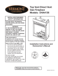
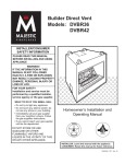
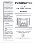
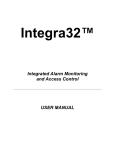
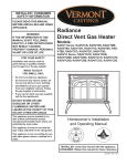
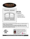
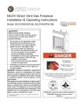
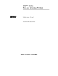
Direct Vent Model:
DVR28IN
� � � � � ��
� � �� � � � � �
��
��������
Installation Instructions and Homeowner’s Manual
INSTALLER/CONSUMER SAFETY INFORMATION
PLEASE READ THIS MANUAL BEFORE INSTALLING AND USING APPLIANCE
�����
WARNING!
�����������
IF THE INFORMATION
IN
���� THIS MANUAL IS NOT
FOLLOWED EXACTLY, A FIRE OR EXPLOSION MAY
RESULT CAUSING PROPERTY DAMAGE, PERSONAL
INJURY OR LOSS OF LIFE.
WHAT TO DO IF YOU SMELL GAS:
• Do not try to light any appliance.
• Do not touch any electric switch; do not use
any phone in your building.
• Immediately call your gas supplier from your
neighbor’s phone. Follow the gas suppliers
instructions.
• If you cannot reach your gas supplier call the
fire department.
FOR YOUR SAFETY
Installation and service must be performed
by a qualified installer, service agency or
the gas supplier.
DO NOT STORE OR USE GASOLINE OR
OTHER FLAMMABLE VAPORS AND
LIQUIDS IN THE VICINITY OF THIS OR ANY
OTHER APPLIANCE.
INSTALLER: Leave this manual with the appliance CONSUMER: Retain this manual for future reference.
20012301 5/07 Rev. 1
Vermont Castings DVR28 Direct Vent Gas Fireplace
Table of Contents
PLEASE READ THE INSTALLATION & OPERATING INSTRUCTIONS
BEFORE USING APPLIANCE.
Thank you and congratulations on your purchase of a CFM Corporation fireplace.
IMPORTANT: Read all instructions and warnings carefully before starting installation.
Failure to follow these instructions fully may result in a possible fire hazard and will void the warranty.
Installation & Operating Instructions
Important Curing/Burning Instructions .................................................................................................3
Fireplace Dimensions ..........................................................................................................................4
Minimum Clearance Illustrations .........................................................................................................4
Firestop Framing .................................................................................................................................4
Locating Your Fireplace .......................................................................................................................5
Clearance to Combustibles .................................................................................................................5
Installation Instructions ........................................................................................................................5
Mounting the Fireplace ........................................................................................................................5
Gas Specifications, Gas Inlet and Manifold Pressures........................................................................6
High Elevations....................................................................................................................................6
Remote ON/OFF Hi/Lo Wall Mounted Transmitter ..............................................................................6
Gas Line Installation ............................................................................................................................6
DVR28 Wiring Diagram .......................................................................................................................7
Restrictor Plate Installation ..................................................................................................................7
General Venting Information
General Venting ...................................................................................................................................8
General Venting - Termination Location ..............................................................................................9
General Venting - Assembling Vent Pipes .........................................................................................10
How to Use the Vent Graph ...............................................................................................................11
Rear Wall Venting Applications and Installation................................................................................. 11
Vertical Side Wall Venting Applications and Installation ....................................................................13
Below Grade Installation....................................................................................................................14
Vertical Through-the-Roof Applications and Installation ....................................................................14
Venting Components .........................................................................................................................17
Operating Instructions
Glass Information ..............................................................................................................................18
Window Frame Assembly Removal ...................................................................................................18
Glass Cleaning ..................................................................................................................................18
Removal and Re-fitting of Curve Face ..............................................................................................18
Flame & Temperature Adjustment .....................................................................................................19
Flame Characteristics ........................................................................................................................19
Inspecting the Venting System ..........................................................................................................19
Lighting & Operating Instructions ......................................................................................................20
Troubleshooting .................................................................................................................................21
Maintenance
Cleaning the Standing Pilot Control System......................................................................................24
Replacement Parts.........................................................................................................................................25
Accessories
Curve Face Kit ...................................................................................................................................26
Screen Door Kit .................................................................................................................................26
Warranty..........................................................................................................................................................27
Energuide .......................................................................................................................................................28
2
20012301
Vermont Castings DVR28 Direct Vent Gas Fireplace
Installation & Operating Instructions
This gas appliance must be installed by a qualified
installer, preferably NFI or WETT (Canada) certified,
in accordance with local building codes and with
current CSA-B149.1 Installation codes for Gas Burning
Appliances and Equipment. For USA Installations follow
local codes and/or the current National Fuel Gas Code.
ANSI Z223.1/NFPA 54.
In the Commonwealth of Massachusetts, all gas
fitting and installation of this heater shall only be
done by a licensed gas fitter or licensed plumber.
FOR SAFE INSTALLATION AND OPERATION PLEASE
NOTE THE FOLLOWING:
1. This fireplace gives off high temperatures and should
be located out of high traffic areas and away from
furniture and draperies.
2. Children and adults should be alerted to the hazards
of high surface temperatures of this fireplace and
should stay away to avoid burns or ignition of clothing.
3. CAUTION: Due to high glass surface temperature
children should be carefully supervised when in
the same room as fireplace.
4. Under no circumstances should this fireplace be modified. Parts removed for servicing should be replaced
prior to operating this fireplace again.
5. A professional service person should be contacted to
inspect this fireplace annually. Make it a practice to
have all of your gas fireplaces checked annually. More
frequent cleaning may be required due to excess lint
and dust from carpeting, bedding material, etc.
6. Control compartments, burners and air passages in
this fireplace should be kept clean and free of dust
and lint. Make sure the gas valve and pilot light are
turned off before you attempt to clean this fireplace.
7. The venting system (chimney) of this fireplace should
be checked at least once a year and if needed your
venting system should be cleaned.
8. Keep the area around your fireplace clear of combustible materials, gasoline and other flammable vapor and
liquids. This fireplace should not be used as a drying
rack for clothing, nor should Christmas stockings or
decorations be hung on or around the fireplace.
9. Under no circumstances should any solid fuels (wood,
coal, paper or cardboard etc.) be used in this fireplace.
10. The flow of combustion and ventilation air must not be
obstructed in any way.
11. When fireplace is installed directly on carpeting, vinyl
tile or any combustible material other than wood, the
fireplace must be installed on a metal or wood panel
extending the full width and depth of the fireplace.
12. This fireplace requires adequate ventilation and
combustion air to operate properly.
20012301
13. This fireplace must not be connected to a chimney
flue serving a separate solid fuel burning fireplace.
14. When the fireplace is not in use it is recommended
that the gas valve be left in the OFF position.
WARNING: Check with your electronics manufacturer
before installing a television or other electronic device above this fireplace.
DVR28IN
Certified To
ANSI Z21.88-2005 / CSA 2.33-2005
Vented Gas Fireplace Heaters
This appliance may be installed in an aftermarket permanently located, manufactured home or mobile home,
where not prohibited by local codes.
This appliance is only for use with the type of gas indicated on the rating plate. This appliance is not convertible
for use with other gases, unless a certified kit is used.
IMPORTANT:
PLEASE REVIEW THE FOLLOWING CAREFULLY
Remove any plastic from trim parts before turning the
fireplace ON.
It is normal for fireplaces fabricated of steel to give off
some expansion and/or contraction noises during the
start up or cool down cycle. Similar noises are found
with your furnace heat exchanger or car engine.
It is not unusual for your gas fireplace to give off some
odor the first time it is burned. This is due to the curing of
the paint and any undetected oil from the manufacturing
process.
Please ensure that your room is well ventilated open all windows.
It is recommended that you burn your fireplace for at
least ten (10) hours the first time you use it. If the optional
fan kit has been installed, place the fan switch in the
“OFF” position during this time.
Proposition 65 Warning: Fuels used in gas, woodburning or
oil fired appliances, and the products of combustion of such
fuels, contain chemicals known to the State of California to
cause cancer, birth defects and other reproductive harm.
California Health & Safety Code Sec. 25249.6
3
Vermont Castings DVR28 Direct Vent Gas Fireplace
DVR28 Fireplace Dimensions
Finished Wall
6���”
(162 mm)
1“ (25 mm) Min.
19���”
(492 mm)
15����"
(395 mm)
14�����”
(377 mm)
28” (711 mm)
12”
(305 mm)
Min.
Finished Wall
Fig. 1 Fireplace specifications and framing dimensions.
Minimum Ceiling and
Floor Clearance
Side View
24”
27” (610 mm)
(686 mm) Min.
Ceiling
Finished Wall
Typ. 16” (406 mm) o.c.*
12301
DVR28 specs
3/07
Top of Unit
10���”
(264 mm)
NOTE: Minimum
clearances are with
face trim in place.
1“
(25 mm)
Min.
9���”
(238 mm)
10”
(254 mm)
Min.
Floor
FP1782
Minimum Side Wall Clearance
FP1783
Fig. 3 Firestop framing.
FP1782
DVR29 min. clearances
3/07
Curve Face Trim
6“
(152 mm)
Min.
������
����������������
����
Top View
FP1784
Fig. 2 Minimum clearances.
20012301
4
������
Vermont Castings DVR28 Direct Vent Gas Fireplace
3. Make sure framing for firestop is correct. NOTE:
Firestop is for combustible walls. Refer to firestop
framing instructions on Pages 4 and 12, Figures 4
and 17.
4. Plumb for gas connection. Refer to Gas Line Installation on Page 6.
5. Finish wall as desired.
CAUTION: If wall is finished with combustible
materials, be sure to install firestop according
to instructions.
Locating Your Fireplace
E
A
B
Y
C
Y
X
D
B
F
Mounting the Fireplace
LU584-R
Fig. 4 Locate gas fireplace.
A) Flat on wall
D) *Room divider
Y) 6” minimum
B) Cross corner
E) *Flat on wall corner
LU584-1
Locating unit
2/4/99 djt
C) **Island
F) Chase installation
NOTE: (Fig. 4)
** Island (C) and Room Divider (D) installation is possible as
long as the horizontal portion of the vent system (X) does not
exceed 20’ (610 cm). See details in Venting Section.
* When you install your fireplace in(D) Room divider or (E)
Flat on wall corner positions (Y), a minimum of 6” (153 mm)
clearance must be maintained from the perpendicular wall and
the front side edge of the fireplace.
Refer to (Y) in Figure 4.
Clearance to Combustibles
Front of Unit to Combustibles ...................36” (914 mm)
Appliance
Top of Unit to Ceiling ..........................27” (686 mm)
Top of Face Trim to Ceiling ........ 24” (610 mm) Min.
Bottom of Unit to Floor .......................12” (305 mm)
Side of Unit to Sidewall ...................10¹⁄₂” (267 mm)
Back .......................................................1” (25 mm)
Venting
Concentric sections of DV Vent ....................1” (25 mm)
Nonconcentric sections of DV Vent
Sides and Bottom ...................................1” (25 mm)
Top .........................................................2” (51 mm)
Installation Instructions
Preparation
Check fireplace to make sure it is levelled
and properly positioned.
1. Choose the location for the fireplace. Maintain
proper height and clearances.
2. Make sure framing is 16” (406 mm) o.c. for placement of wall mount brackets pre-drilled holes. If
framing is not 16” o.c., the installer can drill new
holes in wall mounting brackets to align with existing
framing dimensions.
20012301
CAUTION: DO NOT place fireplace on floor
or hard surface with bottom side down,
components could be damaged.
1. The DVR28 comes with a wall mount bracket to
secure the fireplace to the wall. Standoffs on the
back of the bracket allow for proper clearances to
combustibles. (Fig. 5)
16” o.c.
(406 mm)
Finished
Wall
Firestop
Framing
(if required)
Wall Mounting
Bracket
FP1786
Fig. 5 Secure wall mounting bracket in desired location.
2. Align pipe clearance hole in wall mounting bracket
with through-the-wall clearance opening on noncombustible wall or through firestop opening on combustible walls.
3. Make sure wall mount������
bracket is level. Secure to
framing studs using mounting
screws supplied. En������������
sure framing is 16” (406
mm)
o.c.
to accommodate
����
mounting bracket.
4. Align the top and bottom mounting holes of the fireplace with the top and bottom holes of the mounting
bracket. Secure fireplace to mounting bracket using
sheet metal screws supplied. (Fig. 6)
CAUTION: Be careful to avoid damaging the
electric components located on the bottom of
the fireplace when securing to the mounting
bracket.
5
Vermont Castings DVR28 Direct Vent Gas Fireplace
Gas Line Installation
Sheet Metal
Screws (8)
When purging the gas lines, the front window frame assembly must be removed.
Wall Mounting Bracket
Secured to Walll
DVR28
Sheet Metal
Screws (4)
FP1785
Fig. 6 Secure fireplace to wall mounting bracket.
The gas pipeline can be brought in under the bottom of
the fireplace. The gas line connections will be covered
by bottom trim. Refer to Figure 7 for gas line dimensions. Use 1/2” rigid pipe. When gas line is in place under the fireplace, install supplied 1/2” FPT to 3/8” flare
brass fitting. Connect preinstalled flex line on fireplace
to brass fitting with 3/8” flare fitting on supply line.
The gas line connection can be made with 3/8” rigid
pipe or an approved flex connector. Since some municipalities have additional local codes, it is always best to
consult your local authority and the National Fuel Gas
Code, ANSI Z223.1/NFPA 54 in the USA or the CSAB149.1 installation code.
Gas Specifications
Model
Fuel
DVR28IN
Nat.
������
Max.
Min.
����������������Input Input
����Control BTU/h BTU/h
Gas
Air
Shutter
Setting
1/8”
Millivolt Hi/Lo 18,500 16,500
open
on sides
Gas Inlet and Manifold Pressures
Inlet Minimum
Inlet Maximum
Manifold Pressure
Natural
5.5” w.c.
14.0” w.c.
3.5” w.c.
High Elevations
Input ratings are shown in BTU per hour and are
certified without deration for elevations up to
4,500 feet (1,370m) above sea level.
For elevations above 4,500 feet (1,370m) in USA,
installations must be in accordance with the current ANSI Z223.1/NFPA 54 and/or local codes having jurisdiction.
In Canada, please consult provincial and/or local
authorities having jurisdiction for installations at
elevations above 4,500 feet (1,370m).
Remote ON/OFF Hi/Lo
Wall Mounted Transmitter
The DVR28 is equipped with a wireless transmitter. No
wires are required.
6
12���”
(318 mm)
1���”
(32 mm)
6”
(152 mm)
Gas Line
Through Wall
Gas Line
Opening in
Wall
FP1787
Fig. 7 Recommended gas line installation.
Always check for gas leaks with a mild
soap and water solution applied with a
brush no larger FP1787
than 1” (25 mm). Never
line
installwith a spray
apply soap and gas
water
solution
3/07
bottle. Do not use
an open flame for leak
testing.
The fireplace valve must not be subjected
to any test pressures exceeding 1/2 psi.
Isolate or disconnect this or any other gas
appliance control form the gas line when
pressure testing.
The gas control is equipped with a captured screw type
pressure test point, therefore it is not necessary to provide a 1/8” test point up stream of the control.
When using a flex connector use only approved fittings.
Always provide a union when using black iron pipe
so the gas line can be easily disconnected for burner
servicing. See gas specification for pressure details and
ratings.
The fireplace valve must not be subjected to any test
pressures exceeding 1/2 psi. Isolate or disconnect this
and any other gas appliance control from the gas line
when pressure testing.
20012301
Vermont Castings DVR28 Direct Vent Gas Fireplace
Wireless Remote
White
Green
Orange
ON
OFF
HI/LO DC
Motor Drive
Pilot
Main
Module
HI
AF-4000
LO
Red
AF-4000B/P
Black
Red
Black
Red
Black
No wiring required.
(Refer
to Pages 6,19, 23)
FP1796
Orange
Wireless remote
3/07
Brown
Black
Brown
Brown
HI/LO DC Battery Pack
FP1750
(SWI)
(SWI)
Gnd
Black
Red
Optional DC
Battery Back-up
Fig. 8 DVR28 wiring diagram.
Restrictor Plate Installation
Flue Diverter
The DVR28IN is shipped with a restrictor plate for extended pipe runs other than straight out installations. A
guide for usage is shown in Figure 10.
NOTE: Some installations may require some adjustFP1750
FP1789
DVR28 wiring diagram
ment by the installer for optimum flame appearance.
2/07
Flue
Optimum flame appearance would be a flame not
Opening
subject to tall dirty yellow flames or lifting of flames from
Remove
burner tube.
Two (2)
Installation
1. Remove front glass assembly. Refer to Window
Frame Removal section on Page 18.
2. Remove three (3) screws securing flue diverter to top
of combustion case. Remove flue diverter. (Fig. 9)
CAUTION: Use care not to damage rear refractory.
3. Remove two (2) screws on sides of flue opening.
4. Install restrictor plate with two (2) screws removed
from back of unit. (Fig. 9)
5. Re-install flue diverter with three (3) screws removed
earlier.
6. Reinstall glass assembly. (Refer to Page 18)
Screws
Remove
Three (3)
Screws
Restrictor
Plate
Fig.
r to
10
Refe
FP1788
FP1790
Fig. 9 Install restrictor plate for optimum flame appearance.
������
Examples for Extended Run/Restrictor Plate Settings
���������������
1. 90° Elbow, vertical 8’ (2.4 m), 90° elbow, out 20’ (6 m)
���� 11’ (3.4 m), 90° elbow, out 13’ (4 m)
2. 90° Elbow, vertical
3. 90° Elbow, vertical 20’ (6 m), 90° elbow, out 7’ (2 m)
4. 90°, 40’ (12 m) vertical
Flue restricted to
:
������
1.
2.
3.
4.
������
������������������
1¹⁄₈” (29 mm)
opening in flue pipe outlet
�������������
����
����
7/8” (22 mm)
opening in flue pipe outlet
3/4” (79 mm) opening in flue pipe outlet
1³⁄₈” (35 mm) opening in flue pipe outlet
Figure 10
20012301
7
Vermont Castings DVR28 Direct Vent Gas Fireplace
General Venting
Your fireplace is approved to be vented either through
the side wall, or vertically through the roof.
• Only CFM Corporation venting components specifi•
•
•
cally approved and labelled for this fireplace may be
used.
If vent termination is installed in an accessible location, Vent Termination Guard #53525 shall be installed.
Vent terminations shall not be recessed into a wall or
siding.
Horizontal venting which incorporates the twist lock
pipe must be installed on a level plane without an
inclining or declining slope.
There must not be any obstruction such as bushes,
garden sheds, fences, decks or utility buildings within
24” (610 mm) from the front of the termination hood.
Do not locate termination hood where excessive snow
or ice build up may occur. Be sure to check vent termination area after snow falls, and clear to prevent accidental blockage of venting system. When using snow
blowers, make sure snow is not directed towards vent
termination area.
Location of Vent Termination
It is imperative the vent termination be located observing the minimum clearances as shown on the next
page.
*Check with local codes or in absence of same with
CSA B149.1 Installation Codes (1991) for Canada
or follow the current National Fuel Gas Code, ANSI
Z223.1/NFPA 54 for installations in the USA.
8
20012301
Vermont Castings DVR28 Direct Vent Gas Fireplace
General Venting Information - Termination Location
INSIDE
CORNER DETAIL
G
V
H
A
N
N
D
L
V
E
C
B
V
F
B
�����
������
B
V
Ope
Operable
rable
V
B
B
B
J
X
X AIR SUPPLY INLET
M
I
A
CFM145a
V VENT TERMINATION
V
V
Fixed
Closed
V
K
X
AREA WHERE TERMINAL IS NOT PERMITTED
Canadian Installations1
US Installations2
A = Clearance above grade, veranda, porch,
deck, or balcony
B = Clearance to window or door that may be
opened
CFM145a
12”
(30 cm)
DV Termin
Location
C = Clearance to permanently closed window
12” (305 mm) recommended to
prevent window condensation
6” (15 cm) for appliances
< 10,000 Btuh (3kW), 9”
(23 cm) for appliances > 10,000
Btuh (3kW) and < 50,000 Btuh
(15kW), 12” (30 cm) for
appliances > 50,000 Btuh (15kW)
12” (305 mm) recommended to
prevent window condensation
18” (458 mm)
18” (458 mm)
12” (305 mm)
see next page
see next page
3’ (91 cm) within a height of 15’ (5 m)
above the meter/regulator assembly
12” (305 mm)
see next page
see next page
3’ (91 cm) within a height of 15’
(5 m) above the meter/regulator
assy
3’ (91 cm)
6” (15 cm) for appliances
< 10,000 Btuh (3kW), 9”
(23 cm) for appliances > 10,000
Btuh (3kW) and < 50,000 Btuh
(15kW), 12” (30 cm) for
appliances > 50,000 Btuh (15kW)
3’ (91 cm) above if within 10
feet (3 m) horizontally
7’ (2.13 m)†
D = Vertical clearance to ventilated soffit located
above the terminal within a horizontal
distance of 2’ (610mm) from the center
line of the terminal
E = Clearance to unventilated soffit
F = Clearance to outside corner
G = Clearance to inside corner (see next page)
H = Clearance to each inside of center line
extended above meter/regulator assembly
5/01/01 Rev. 12/05/01
sta
6” (15 cm) for appliances
< 10,000 Btuh (3kW), 12” (30 cm)
for appliances > 10,000 Btuh (3kW) and
< 100,000 Btuh (30kW), 36” (91 cm)
for appliances > 100,000 Btuh (30kW)
I = Clearance to service regulator vent outlet
J = Clearance to nonmechanical air supply inlet
to building or the combustion air inlet to any
other appliances
3’ (91 cm)
6” (15 cm) for appliances < 10,000 Btuh
(3kW), 12” (30 cm) for appliances
> 10,000 Btuh (3kW) and < 100,000 Btuh
(30kW), 36” (91cm) for appliances
> 100,000 Btuh (30kW)
K = Clearance to a mechanical air supply inlet
6’ (1.83 m)
12” (30 cm)
L = Clearance above paved sidewalk or paved 7’ (2.13 m)†
driveway located on public property
M = Clearance under veranda, porch, deck or
12” (30 cm)‡
12” (30 cm)‡
balcony
N = Clearance above a roof shall extend a minimum of 24” (610 mm) above the highest point when it passes through the roof
surface, and any other obstruction within a horizontal distance of 18” (450 mm).
1 In accordance with the current CSA-B149 Installation Codes
2 In accordance with the current ANSI Z223.1/NFPA 54 National Fuel Gas Codes
† A vent shall not terminate directly above a sidewalk or paved driveway which is located between two single family dwellings and
serves both dwellings
‡ only permitted if veranda, porch, deck or balcony is fully open on a minimum 2 sides beneath the floor:
NOTE: 1. Local codes or regulations may require different clearances.
2. The special venting system used on Direct Vent Fireplaces are certified as part of the appliance, with clearances tested and
approved by the listing agency.
3. CFM Corporation assumes no responsibility for the improper performance of the appliance when the venting system does not
meet these requirements.
Fig. 11 Vent termination locations.
20012301
9
Vermont Castings DVR28 Direct Vent Gas Fireplace
Termination Clearances
Termination clearances for buildings with combustible and noncombustible exteriors.
Inside Corner
Alcove Applications*
Outside Corner
G=
Combustible
6" (152 mm)
G
F=
Combustible
6" (152 mm)
Noncombustible
2" (51 mm)
V
Noncombustible
2" (51 mm)
V
C
V
E
O
F
Balcony with perpendicular side wall
Balcony with no side wall
D
C
E = Min. 6” (152 mm) for
non-vinyl sidewalls
Min. 12” (305 mm) for
vinyl sidewalls
O = 8’ (2.4 m) Min.
M
M
No.
of Caps
1
2
3
4
V
V
P
M=
Combustible &
Noncombustible
12" (305 mm)
Combustible &
Noncombustible
M = 24" (610 mm)
P = 20” (508 mm)
DMin.
3’ (914 mm)
6’ (1.8 m)
9’ (2.7 m)
12’ (3.7 m)
CMax.
2 x DActual
1 x DActual
2/3 x DActual
1/2 x DActual
DMin. = # of Termination caps x 3
CMax. = (2 / # termination caps) x DActual
584-15
*NOTE: Termination in an alcove space (spaces open only on one side and with an overhang) is permitted with the dimensions
specified for vinyl or non-vinyl siding and soffits. 1. There must be a 3’ (914 mm) minimum between termination caps. 2. All
mechanical air intakes within 10’ (1 m) of a termination cap must be a minimum of 3’ (914 mm) below the termination cap. 3. All
gravity air intakes within 3’ (914 mm) of a termination cap must be a minimum of 1’ (305 mm) below the termination cap.
Fig. 12 Termination clearances.
General Information Assembling Vent Pipes
Canadian Installations:
USA Installations:
until the flange on the female end contacts the external
flange on the male end. It is recommended that you
secure the joints with three (3) sheet metal screws,
however this is not mandatory with twist lock pipe.
The venting system must conform with local codes and/
or the current National Fuel Gas code ANSI Z223.1/
NFPA 54.
To make it easier to assemble the joints we suggest
putting a lubricant (Vaseline or similar) on the male end
of the twist lock pipe prior to assembly.
Venting system must be installed in accordance with the
current CSA-B149.1 installation code.
Only venting components manufactured by CFM Corporation can be used in Direct Vent systems.
Male End
Female End
Twist Lock Pipes
When using CFM Corporation twist-lock pipe it is not
necessary to use sealant on the joints. The only areas
of the venting system that need to be sealed with high
temperature silicone sealant are the sliding joints of any
telescopic vent section used in the system.
To join the twist lock pipes together, simply align the
beads of the male end with the grooves of the female
end, then while bringing the pipe together, twist the pipe
10
Screw Holes
TWL100
Fig. 13 Twist-lock pipe joints.
TWL100
Twist Lock Pipe
3/12/99 djt
20012301
Vermont Castings DVR28 Direct Vent Gas Fireplace
How to Use the Vent Graph
Rear Wall Venting Applications
The vent chart should be read in conjunction with the
following vent installation instructions to determine the
relationship of the vertical and horizontal dimensions of
the vent system.
1. Determine the height of the center of the horizontal
vent pipe exiting through the outer wall. Using this
dimension on the Sidewall Vent Graph (Fig. 14)
locate the point intersecting with slanted graph line.
2. From the point of this intersection, draw a vertical
line to the bottom of the graph.
3. Select the indicated dimension, and position the
fireplace in accordance with same.
Example A:
If the vertical dimension from the floor of the
fireplace is 11’ (3.4 m) the horizontal run to the face
of the outer wall must not exceed 14’ (4.3 m).
Example B:
If the vertical dimension from the floor of the unit is
7’ (2.14 m), the horizontal run to the face of the outer
wall must not exceed 8¹⁄₂’ (2.6 m).
When installed as a rear vent unit this appliance may
be vented directly to a termination located on the rear
wall behind the appliance.
• Only CFM Corporation venting components are
•
•
•
•
approved to be used in these applications. (Refer to
“Venting Components” listed for different installation
requirements)
The maximum horizontal distance between the rear
of the appliance (or end of the transition elbow in a
corner application) and the outside face of the rear
wall is 20” (508 mm). (Fig. 15 & 16)
Only one 45° elbow is allowed in these installations.
If using a 45° elbow at fireplace, you must start
out using an 8” (203 mm) or 12” (305 mm) section of pipe first attached to heater then a 45°
elbow.
Minimum clearances between vent pipe and combustible materials are as follows:
Top - 2” (51 mm)
Sides - 1” (25 mm)
Bottom - 1” (25 mm)
30
29
28
27
26
25
23
22
21
20
19
18
17
16
15
14
13
eg: A
12
11
10
9
8
7
eg: B
6
Vertical dimension from the floor of the unit
to the center of the horizontal vent pipe
24
20”
(508 mm)
Max.
Rear Vent Top View
FP1780
Fig. 15 Rear vent application, no elbows.
FP1780
20”
20”
(508 mm)
(508 mm)
rear
vent
no
elbows
Max.
Max.
3/07
45°
45°
5
4
3
�������� ����� ����������������������������������������������������������������
Horizontal dimension from the outside face of the
wall to the center of the fireplace vent flange
Sidewall vent graph showing the relationship between vertical
and horizontal dimensions for a Direct Vent flue system.
Fig. 14 Sidewall venting graph. (Dimensions in feet)
20012301
FP1779
Start with 8” (203 mm) or 12”
(305 mm) Pipe Section
Fig. 16 Rear vent application, one 45° elbow.
FP1779
Rear Vent-Top View
3/07
11
Vermont Castings DVR28 Direct Vent Gas Fireplace
Rear Wall Installation
Twist Lock Pipe
Adjustable
Zero Clearance
Sleeve
Max. Length
12” (305mm)
#8 Screws (2)
STEP 1
Locate vent opening on the wall. To locate hole center
consult with appropriate fireplace dimensions, Page 4.
Frame as shown below.
#8 Screws
(2)
#8 Screws
(2)
Combustible Walls (Fig. 17): Cut a 10³⁄₈”H x 9³⁄₈” W
(264 x 240 mm) hole through the exterior wall and
frame as shown.
Firestop
Noncombustible Walls (Fig. 17): Hole opening must
be 7¹⁄₂” (190 mm) in diameter.
Zero clearance sleeve is only required for
combustible walls.
STEP 2
Measure wall thickness and cut zero clearance sleeve
parts to proper length (MAXIMUM 12”/305 mm). Assemble sleeve and attach to firestop with #8 sheet metal
screws (supplied). (Fig. 18)
STEP 3
Measure the horizontal length requirement for the venting including a 2” (51 mm) overlap, i.e. from the elbow
to the outside wall face plus 2” (51 mm). (Fig. 15 or 16)
Vent Opening for Combustible Wall
Framing
Detail
Fireplace Hearth
Firestop
Install provided firestop with zero
clearance sleeve into framing
opening after drywall or finish
material is installed. Use the tabs
for clearance locators top and
bottom.
Top Tabs
ZCS101
Fig. 18 AdjustableFP1752
zero clearance sleeve.
Zero Clearance Sleeve
2/07
STEP 4
Install the 4” (102 mm) vent to the appliance collar and
secure with three (3) sheet metal screws. Install the 7”
(178 mm) vent pipe to the appliance collar and secure
with three (3) sheet metal screws. It is not necessary
to seal this connection. If a 45° elbow is being used,
attach the elbow to the appliance in the same manner
then attach the venting to the elbow.
It is critical there is no downward slope
away from the appliance when connecting
the vent or elbow.
STEP 5
Guide the venting through the vent hole a you place the
appliance in its installed position. Guide the 4” (102 mm)
and 7” (178 mm) collar of the vent termination into the
outer ends of the venting. Do not force the termination. If
the vent pipes do not align with the termination, remove
and realign the venting at the appliance flue collars.
(Fig. 19) Attach the termination to the wall as outlined in
the instruction sheet supplied with the termination.
9³⁄₈”
(240mm)
10³⁄₈”
(264mm)
Adjustable Zero Clearance Sleeve
Opening for
Noncombustible Wall
Finished Wall
Firestop
Vent
Termination
7¹⁄₂”
(190 mm)
Bottom Tabs
FP1751
Zero Clearance
Sleeve
Fig. 17 Locate vent opening on wall.
FP1751
vent opening
2/07
12
FP1753
Fig. 19 Side view of final unit location.
FP1005
Side View Vent Termination
1/25/00 djt
20012301
Vermont Castings DVR28 Direct Vent Gas Fireplace
Vertical Sidewall Applications
Since it is very important for the venting system
to maintain balance between the combustion air
intake and the flue gas exhaust, certain limitations
as to vent configurations apply and must be strictly
adhered to.
The Vent Graph shows the relationship between vertical
and horizontal side wall venting and will help to determine the various dimensions allowable.
Minimum clearance between vent pipes and combustible materials is 2”(51 mm) on top and 1” (25
mm) on the bottom and sides unless otherwise
noted.
When vent termination exits through foundations less
than 20” below siding outcrop, the vent pipe must
flush up with the siding. It is always best to locate the
fireplace in such a way that minimizes the number of
offsets and horizontal vent length.
The horizontal vent run refers to the total length of vent
pipe from the flue collar of the fireplace to the face of
the outer wall.
Example: According to the vent graph (Page 11) the
maximum horizontal vent length in a system with a 7.5’
(2.3 m) vertical rise is 20’ (6 m) and if a 90° elbow is
required in the horizontal vent it must be reduced to 17’
(5.2 m). In Figure 21 Dimension A plus B must not be
greater than 17’ (5.2 m).
In Figure 21, dimension A plus B must not be greater
than 17’ (5.2 m).
• The maximum number of 45° elbows permitted per
side wall installation is two (2). These elbows can be
installed in either the vertical or horizontal run.
• For each 45° elbow installed in the horizontal run,
the length of the horizontal run MUST be reduced by
18” (45 cm). This does not apply if the 45° elbows
are installed on the vertical part of the vent system.
• The maximum number of elbow degrees in a system
is 270°. (Fig. 22)
Example:
Elbow 1 = 90°
Elbow 2 = 45°
Elbow 3 = 45°
Elbow 4 = 90°
Total angular variation = 270°
Horizontal plane means no vertical rise exists on this
portion of the vent assembly.
B 7’
(178 cm)
When installing the appliance as a rear
vent unit, the 90° or 45° transition elbow
is NOT INCLUDED in the following criteria
and calculations, and unless specifically
mentioned should be ignored when calculating venting layouts.
• The maximum number of 90° elbows per side wall
installation is three (3). (Fig. 20)
A 10’
(254 cm)
A + B = 17’
(518 cm) Max.
8’
(244 cm)
3 x 90°
Elbows
FP1755
Fig. 21 Maximum vent run with elbows.
1 + 2 + 3 + 4 = 270°
FP1755
Horizontal Run
2/07
1
FP1754
Fig. 20 Maximum three (3) 90° elbows per installation.
• If a 90° elbow is used
in the horizontal vent run
������
(level height maintained)
the maximum horizontal
������������
vent length is reduced by 36” (914 mm). This does
����
2
3
4
not apply if the 90° elbows are used to increase or
redirect a vertical rise. (Fig. 21)
FP1756
Fig. 22 Maximum elbow usage.
20012301
������
�������������
����
13
Vermont Castings DVR28 Direct Vent Gas Fireplace
Do not backfill around snorkel.
Below Grade Installations
When it is not possible to meet the required vent terminal clearances of 12” (305 mm) above grade level
a snorkel kit is recommended. This allows installation
depth of down to 7” (178 mm) below grade level. The
7” is measured from the center of the horizontal vent
pipe as it penetrates through the wall.
Ensure the sidewall venting clearances are observed.
If venting system is installed below ground, we recommend a window well with adequate and proper drainage
to be installed around the termination.
If installing a snorkel, a minimum 24” (610 mm) vertical
rise is necessary. The maximum horizontal run with the
24” vertical pipe is 36” (914 mm). This measurement
is taken from the collar of the fireplace (or transition
elbow) to the face of the exterior wall. See the Sidewall
Venting Graph for extended horizontal run if the vertical
exceeds 24” (610 mm).
1. Establish vent hole through the wall. (Fig. 17)
2. Remove soil to a depth of approximately 16”
(406 mm) below base of snorkel. Install window
well (not supplied). Refill hole with 12” (305 mm) of
coarse gravel leaving a clearance of approximately
4” (102 mm) below snorkel. (Fig. 23)
3. Install vent system. Refer to Page 12.
4. Ensure a watertight seal is made around the vent
pipe coming through the wall.
5. Apply high temperature sealant caulking (supplied)
around the 4” and 7” snorkel collars.
6. Slide the snorkel into the vent pipe and secure to the
wall.
7. Level the soil to maintain a 4” (102 mm) clearance
below snorkel. (Fig. 23)
Zero Clearance Sleeve
(if required)
7TDVSNORK
(Snorkel)
Screws
A clearance of at lest 4” must be maintained between the snorkel and the soil.
If the foundation is recessed, use recess brackets (not
supplied) for securing lower portion of the snorkel. Fasten brackets to wall first, then secure to snorkel with self
drilling #8 x 1/2 sheet metal screws. It will be necessary
to extend vent pipes out as far as the protruding wall
face. (Fig. 24)
Snorkel
Foundation
Recess
Wall Screws
Watertight Seal
Around Pipe
Sheet Metal
Screws
BG401
Fig. 24 Snorkel installation, recessed foundation.
BG401
Vertical Through-the-Roof Application
Snorkel
This gas fireplace
has beendjt
approved for:
2/10/99
• Vertical installations up to 40’ (12 m) in height. Up
to a 10’ (3 m) horizontal vent run can be installed
within the vent system using a maximum of two 90°
elbows. (Fig. 25)
Max. Height 40’
(12.2 m)
Min. Height 8’
(2.4 m)
Max. 10’ (3 m)
Firestop
7” Pipe
4” Clearance Min.
Support Straps
Every 3’ (914 mm)
Window
Well
24” (610 mm )
Minimum *
Gravel
FP1757
Fig. 25 Support straps for horizontal runs.
Drain
• Up to two 45° elbows may be used within the hori-
Foundation Wall
*A minimum of 24” (610 mm)
vertical pipe must be installed
when using the 7TDVSNORK.
BG404
Fig. 23 Below grade installation.
14
�����
�����������
����
zontal run. For each 45° elbow used on the horizontal plane, the
maximum horizontal length must be
������
reduced by �����������������
18” (450 mm).
����� horizontal length:
Example: Maximum
No elbows
= 10’ (3 m)
1 x 45° elbow = 8.5’ (2.6 m)
2 x 45° elbows = 7’ (2.1 m)
20012301
Vermont Castings DVR28 Direct Vent Gas Fireplace
• A minimum of an 8’ (2.5m) vertical rise is required.
• Two sets of 45° elbow offsets may be used within the
•
•
•
vertical sections. From 0 to a maximum of 8’ (2.5 m)
of vent pipe can be used between elbows. (Fig. 26)
7DVCS supports offsets. (Fig. 28) This application
will require that you first determine the roof pitch
and use the appropriate starter kit. (Refer to Venting
Components List)
The maximum angular variation allowed in the system is 270°. (Fig. 26)
The minimum height of the vent above the highest
point of penetration through the roof is 2’ (610 mm).
(Fig. 29)
If there is a room above ceiling level, fire stop spacer
must be installed on both the bottom ad the top side
of the ceiling joists. If an attic is above ceiling level a
7DVAIS (Attic Insulation Shield) must be installed.
The enlarged ends of the vent section always face
downward.
Attic Insulation Shield
Upper Floor
11”
(279mm)
1 + 2 + 3 + 4 = 270°
11”
(279mm)
Ceiling Installation
1
1
2
Joist
2
3
Firestop
Spacer
3
4
4
Nails (4)
FP1029
Fig. 27 Place firestop spacer(s) and secure.
FP1029
attic insulation shield
firestop spacers
1/28/00 djt
FP1179
Fig. 26 Maximum elbow usage.
Vertical Through-the-Roof Installation
1. Locate your fireplace.
2. Plumb to center of the (4”) flue collar from ceiling
above and mark position.
3. Cut opening equal to 9³⁄₈” x 9³⁄₈” (240 x 240 mm).
4. Proceed to plumb for additional openings through
the roof. In all cases, the opening must provide a
minimum of 1 inch clearance to the vent pipe, i.e.,
the hole must be at least 9³⁄₈” x 9³⁄₈” (240 x 240 mm).
5. Place fireplace into position.
6. Place firestop(s) #7DVFS or Attic Insulation Shield
#7DVAIS into position and secure. (Fig. 27)
7. Install roof support (Fig. 44) and roof flashing making
sure upper flange is below the shingles. (Fig. 28)
8. Install appropriate pipe sections until the venting is
above the flashing. (Fig. 30)
9. Install storm collar and seal around the pipe.
10. Add additional vent lengths for proper height. (Fig.
29)
11. Apply high temperature sealant to 4” and 7” collars
of vertical vent termination and install.
20012301
Typical Roof
Support
Application
Fig. 28
Typical Ceiling
Support
Application
Venting FP1184
supports.
Typical roof/ceiling
support apps.
FP1184
15
Vermont Castings DVR28 Direct Vent Gas Fireplace
Min.
2' (610 mm)
3 #5 Sheet Metal
Screws per Joint
Sealant
Storm Collar
TWL101a
Fig. 30 Roof flashing.
FP1185
Fig. 29 Minimum termination to roof clearance.
16
TWL101a
Twist Lock Pipe
2/8/99 djt
20012301
Vermont Castings DVR28 Direct Vent Gas Fireplace
Venting Components
7TDVRVT - Through the wall Rear Vent Termination
584A
venting components
rear vent term
4/6/99 djt
584B
Vent components
Starter Kit
2/25/99 djt
Starter Kit Model 7TDVSK - Sidewall Venting (Twist Lock Pipe)
Model 7FDVSK - Sidewall Venting (Flex Vent Pipe)
Models 7TDVTK/TV - Hot Touch Termination Kits
Model 7TDVTVTK/TV - Cool Touch Termination Kit
Starter Kit - Model 7TDVSKV - Vertical Venting
for 7TDVSKV-A order 1/12 to 6/12 roof pitch
for 7TDVSKV-B order 7/12 to 12/12 roof pitch
for 7TDVSKV-F order flat roof
Starter Kit for Below Grade Installation
Model 7TDVSKS -Snorkel Kit (Twist Lock Pipe)
Model 7FDVSKS -Snorkel Kit (Flex Vent Pipe)
Starter Pipe
Model 7TDVP 20/8 - 24” Starter Pipe Bulk
Model 7FDVP 30/8 - 30” Flex Pipe Bulk
45o Elbow
7TDV45 for Rear Vent to Vertical Vent
or Vertical/Horizontal Offsets
584C
584D
Vent components
Vent
Components
45 degree
elbow
90 degree elbow
2/25/99djt djt
2/25/99
10/20/99
twistlock
584E
10/20/99
twist
lock
Venting Components
Telescope vent
2/25/99 djt
10/20/99 twist lock
584F
Venting Components
Pipe sections
2/25/99 djt
10/20/99 twist lock
584G
Venting Components
Firestop spacer
2/25/99 djt
584H
Venting components
attic insulation shield
2/25/99 djt
20012301
90o Transition Elbow
7TDVRT90 for Rear Vent to Vertical Vent
90° Elbow
7TDV90 Vertical/Horizontal Offset
Telescopic vent sections
7TDVP1117 -11” to 17” adjustable length
7TDVP3567 -35” to 67” adjustable length
Pipe sections for vertical or horizontal venting
Model 7TDVP8”
4 per box
Model 7TDVP12”
4 per box
Model 7TDVP24”
4 per box
Model 7TDVP36”
Model 7TDVP48”
Firestop Spacer
20012362
Attic Insulation Shield
Model 7DVAIS
Vertical/Horizontal Combination Offset Support
Model 7DVCS
17
584I
vent components
Vermont Castings DVR28 Direct Vent Gas Fireplace
Operating Instructions
Glass Cleaning
Glass Information
Only glass approved by CFM Corporation
should be used on this fireplace.
• The use of any non-approved replacement glass will
void all product warranties.
• Care must be taken to avoid breakage of the glass.
• Do not operate appliance with glass front
removed, cracked or broken.
• Replacement glass (complete with gasket and
window frame) is available through your CFM
Corporation dealer and should only be installed
by a licensed qualified service person.
It is necessary to clean the glass periodically. During
start-up condensation, which is normal, forms on the
inside of the glass and causes lint, dust and other
airborne particles to cling to the glass surface. Also
initial paint curing may deposit a slight film on the glass.
It is therefore recommended the glass be cleaned
two or three times with a non-ammonia household
cleaner and warm water (gas fireplace glass cleaner
is recommended). After the initial cleaning process the
glass should be cleaned two or three times during each
operating season depending on the environment in the
house.
Clean the glass after the first two weeks of
operation.
Do not clean glass when hot.
Do not use abrasive cleaners.
Do not strike or slam the glass.
Window Frame Assembly Removal
1. Turn the fireplace OFF (including the pilot).
2. If the unit has been operating, allow time for the
components to cool.
3. Remove two (2) bolts on bottom side of unit holding
front trim face on. (Fig. 32)
4. Remove front trim face by tilting bottom out and lifting face off unit. (Fig. 32)
5. Remove two (2) bolts securing bottom door frame to
unit. (Fig. 31)
6. Tilt window frame assembly out slightly at the bottom, lift the frame up and away from the fireplace.
(Fig. 31)
7. To replace window frame assembly reverse procedure.
Removal and Re-fitting the Curve Face
The Curve face is fitted to the fireplace by hooking the
top edge of the face over the mounting brackets as
shown in Figure 32. Secure with two (2) screws on the
bottom face of the trim. (Fig. 32)
Top Mounting
Brackets
Curve Face
Window Frame
Assembly
Fireplace
Front
Bottom Bracket
Glass
Panel
Control Cover Plate
KT779
Fig. 32 Hang Curve Face in place.
FP1758
Fig. 31 Window frame assembly removal.
������
�������������
����
18
�����
�����������
����
20012301
Vermont Castings DVR28 Direct Vent Gas Fireplace
Flame & Temperature Adjustment
To adjust Hi/Lo setting, push either the high or low control button on remote control transmitter.
ON
OFF
HI
LO
LG480
FP1759
Fig. 35 Correct DVR28 flame. Center flame should be approximately 5¹⁄₂” (140 mm) high.
FP1796
Fig. 33 Flame adjustment
for American Flame valve.
Wireless remote
3/07
Flame Characteristics
It is important to periodically perform a visual check of
the pilot and the burner flames. Compare them to Figures 34-35. If any of the flames appear abnormal call a
service person.
Inspecting the Venting System
�����������������
This appliance
venting system is designed and constructed to����
develop a positive flow adequate to remove
flue gases to the outside atmosphere.
Any foreign objects in the venting system, except those
designed specifically for the venting system, may cause
spillage of flue gases.
To inspect the venting system, make sure the main gas
valve is off. Remove window frame assembly (Refer to
Window Frame Assembly Removal Section). Using a
flashlight, check the area above the baffle in the combustion dome. Clean if necessary.
FP1778
Fig. 34 Correct pilot flame appearance.
������
���������
����
20012301
19
Vermont Castings DVR28 Direct Vent Gas Fireplace
Lighting & Operating Instructions
For Fireplaces equipped with AF4000 Gas Valve
Warning: If you do not follow these instructions exactly, a fire or explosion may
result, causing property damage, personal injury and loss of life.
For Your Safety, Read the Following Warnings
before Lighting the Appliance
•
A. This fireplace is equipped with an ignition device
which automatically lights the pilot. DO NOT try to
light the pilot by hand.
B. BEFORE OPERATING, smell all around the
appliance area for gas. Be sure to smell next to
the floor because some gas is heavier than the
air and will settle on the floor.
What to do if you smell gas
• Do not try to light any appliance.
• Do not operate any electrical switch.
• Do not use any phone in your building.
•
Immediately call your gas supplier from
a neighbor’s phone. Follow the gas
suppliers instructions.
If you cannot contact your gas supplier call
the Fire Department
C. Do not use this appliance if any part has been
under water. Immediately call a qualified service
technician to inspect the appliance and replace
any part of the control system and any gas control
that has been under water.
Lighting Instructions
Spark to Pilot
1. STOP! Read the safety information above before
Pilot Assembly
continuing.
2. This appliance is equipped with an ignition device
“S” Connection
which automatically lights the pilot. DO NOT try to
Connect to Module
light the pilot by hand.
3. Access the gas control by removing the side cover
Pilot Adjustment
access door on the left side of the unit.
Screw
Pilot Gas Connection
4. Turn the remote switch, if used, OFF. Turn the Inlet Pressure
Side or Back
wireless remote, if used, OFF.
Tap
“I” Connection
Connect to
5. Wait five (5) minutes to clear out any gas.
Module
Then smell for gas, including near the floor.
If you smell gas, STOP. Follow instruction B
in the safety warnings above. If you do not
smell gas, go on to the next step.
6. Close the access door.
7. If the appliance will not operate, follow the
instructions TURNING OFF THE GAS TO
THE APPLIANCE, and call your service
Pilot Internal
Main Valve Internal Solenoid
Outlet
technician or gas supplier.
Solenoid
Connection
Connection
Orange &
white Wires
Pressure Tap
Green & White Wires
Turning Off the Gas to the Appliance
1. Turn the remote switch to the OFF position.
2. Turn OFF all electrical power to the fireplace if
service is required.
3. Open the lower access panel.
4. Turn the shut-off valve on the flexible gas line to
the OFF position.
20
1/2” Gas Supply
������
������������
����
1/2” NPT x 3/8” Flare
Shut-Off Valve
3/8” Flex Line
(From Valve)
Valve in the “ON” position
FP297A
20012301
FP297A
INSTA VENT FREE
UVHB26 GAS SUPPLY
7/1/98
Vermont Castings DVR28 Direct Vent Gas Fireplace
Troubleshooting
AF4000 Valve
If erratic system behavior is observed that cannot be resolved by the methods outlined below, ensure that there is
not a transmitter with batteries installed that may be interfering. If a transmitter is packed with batteries installed, its
buttons may be depressed sending a constant signal which can interfere with the transmission of desired signals. A
transmitter with new batteries can have a range of over 100’ (30.4 m).
Module will not learn transmitter
• Ensure the REMOTE/OFF switch on the side of the module (Fig. 36) is set to REMOTE.
• Make sure the batteries in both the transmitter and receiver are installed in the
proper direction (Fig. 39, 40) and are not drained. Individual battery voltage should
be no less than 1.4V for AA and AAA batteries, 2.8V for button cells, and 9,0V for
12V batteries.
• Verify the transmitter indicates a signal is being sent. With thermostat transmitters,
the LCD display should indicate ON or OFF depending on which button is being
pressed. The LED indicator should illuminate on wall transmitters and on/off handheld transmitters. (Fig. 39) Buttons should be pressed and held for 1 to 2 seconds
to ensure a complete signal is sent.
• Make sure the transmitter is within the 20’ (6 m) operational range of the receiver.
• Ensure the 4-pin lead-set is securely connected from the battery pack to the control module’s AUX connection. (Figs. 37) If the A/C power adapter is used, make
sure the leads from the adapter are securely connected to the POWER terminals
on the control module. (Fig. 38)
• Press and hold the LEARN button on the module (Fig. 37) for approximately 10
seconds to clear the memory (you should hear a series of beeps from the receiver). Then press and release the learn button (you should hear a single beep
from the receiver), immediately press either the ON or OFF button on the transmitter (you should hear a series of beeps indicating the transmitter code has been
learned).
Figure 36: AF4000
MOD Module Right
Side
Continuous PIlot
Off/On Switch
Remote/Off
Switch
“S” Pilot Connection
Figure 37: AF4000
MOD Module Left Side
Adjustment
FP1762
“I” Pilot
Connection
Learn Button
AUX Connection
������
������������������������
����
FP1763
20012301
������
�����������������������
����
21
Vermont Castings DVR28 Direct Vent Gas Fireplace
Troubleshooting AF4000 Valve (continued)
Pilot will not light/stay lit
• Verify the gas supply is turned on.
• Verify the receiver is receiving the signal from the transmitter by listening for a
beep from the receiver when ON is pressed on the transmitter. If you do not hear
a beep, ensure the module has learned the transmitter (see above).
• Ensure the orange lead from the pilot assembly igniter is securely connected to
the terminal labeled “I” and the white lead from the flame rectification sensor is
securely connected to the terminal labeled “S” on the control module. (Fig. 36)
• Make sure the orange and white leads from the module are securely connected to
the terminals labeled “PILOT” on the valve body. (Fig. 41)
• Ensure the black GROUND wire is securely connected to an appropriate metal
portion of the valve or pilot assembly. A proper ground is essential to spark
igniter operation.
• Make certain the pilot flame is in contact with the flame rectification sensor on the
pilot assembly. This valve is equipped with a pilot flame adjustment screw. (Fig.
41) If the pilot flame is too small it will not contact the flame rectification sensor
and will not complete the safety circuit.
Figure 38: AF4000 MOD Module End
6 Volt DC Adapter
Power Connection
8 Pin IPI
Connection
FP1764
Figure 39: Wall Transmitter Face
Indicator Light
������
�����������������
����
30 MIN
60 MIN
120 MIN
Insert batteries
into holder and
snap into holder.
OFF
+
Plus
Side
+
Plus
Side
FP1766
FP1766
wall transmitter face
2/07
22
20012301
Vermont Castings DVR28 Direct Vent Gas Fireplace
Troubleshooting AF4000 Valve (continued)
Pilot flame is always on/ will
not extinguish
Main flame will not light
• Ensure the CONTINUOUS PILOT switch on the control module (Fig. 36) is set
to OFF.
• Verify the gas supply is turned on.
• Ensure the pilot flame will ignite. If not, see pilot flame troubleshooting above.
• Make sure the green and white leads from the module are securely connected to
the terminals labeled “MAIN: on the valve body. (Fig. 41)
• Make certain the pilot flame is in contact with the flame rectification sensor on
the pilot assembly. This valve is equipped with a pilot flame adjustment screw.
(Fig. 41) If the pilot flame is too small it will not contact the flame rectification
sensor and will not complete the safety circuit.
Flame height adjustment will
not work/works backwards
• Ensure the pilot flame is properly located to ignite the main flame.
• Ensure the black and red leads from the battery pack or the AF4000 110H/L
module are securely connected to the red and black leads from the motor drive
or H/L latching solenoid located on the valve body (red to red and black to
black).
• Verify the selector switch on the battery pack is set to DC MOTOR DRIVE or
LATCHING SOLENOID, depending upon which device is installed. (Fig. 40)
• Check functionality with all transmitters to determine if there is an issue with the
main control system or an individual transmitter. If the issue is with an individual
transmitter, make sure the batteries in both the transmitter and receiver are installed in the proper direction (Fig. 39, 40) and are not drained. Individual battery
voltage should be no less than 1.4V for AA and AAA batteries, 2.8V for button
cells, and 9.0V for 12V batteries.
Figure 40: Battery Pack - Battery Compartment
Latching Solenoid / DC Motor Drive
+
-
Selector Switch
Figure 41: AF4000 Valve Face
+
-
FP1767
FP1767
battery pack
2/07
MAIN
Main Connection
Inlet
Pilot Adj.
PILOT
Outlet
FP1769
Pilot Connection
20012301
23
FP1769
AF4000 valve face
Vermont Castings DVR28 Direct Vent Gas Fireplace
Maintenance
Burner and Burner Compartment
It is important to keep the burner and the burner
compartment clean. At least once per year the burner
compartment should be vacuumed and wiped out.
Cleaning the Standing
Pilot Control System
The burner and control system consists of
• burner tube
• pilot assembly
• gas valve
• gas orifice
Most of these components may require only an occasional checkup and cleaning and some may require
adjustment. If repair is necessary, it should be performed by a qualified technician.
To obtain proper operation, it is imperative that the pilot
and burner’s flame characteristics are steady, not lifting
or floating.
Typically, the top 3/8” or 1/2” of the thermopile should
be engulfed in the pilot flame. (Fig. 42)
To adjust pilot burner; (by qualified service technician)
1. Remove pilot adjustment cap.
2. Adjust pilot screw to provide properly sized flame.
3. Replace pilot adjustment cap.
The primary air shutter is set at the factory and should
only be adjusted, if necessary, by a qualified service
technician.
Fireplace May Be HOT!!
1. Turn off pilot light at remote wall switch.
2. Let fireplace cool if it has been running.
3. Remove window frame assembly. (Refer to Window
Frame Assembly Removal section)
4. Vacuum burner compartment especially around
orifice primary air openings.
5. Visually inspect pilot. Brush or blow away any dust
or lint accumulation.
FP1778
Fig. 42 Correct pilot flame appearance.
������
���������
����
6. Ignite pilot - Refer to Lighting Instructions.
7. Reinstall window frame assembly.
24
20012301
Vermont Castings DVR28 Direct Vent Gas Fireplace
2
1
3
4
5
6
7
11
9
10
8
13
17
12
15
16
14
CFM Corporation reserves the right to make changes in design, materials, specifications, prices and discontinue colors and products at any time,
without notice.
DVR28IN (GFYN4G0)
Ref.
1.
2.
3.
4.
5.
6.
7.
8.
9.
10.
11.
12.
13.
14.
15.
16.
17.
Description
Burner Tube
Rear Refractory
Ceramic Retainer
Bracket, Upper Trim
Lower Bracket Assembly
Valve Assy, VF4000
Main Module
SIT Pilot Assembly
24” Wire Harness 8-Pin, 8-Wire
Battery Power Pack
Solenoid Remote Hi/Lo
Glass Frame Assembly
On/Off HI/LO Remote Control
Restrictor Plate
Wall Mount Assy.
Burner Orifice #45 (.0820”)
Firestop
20012301
12301
DVR28 parts
3/07
DVR28
20012266
20011551
20012350
20011581
20011579
20012290
20011895
20012381
20012258
20012263
20012265
20011597
20012267
20012396
20012219
20012302
20012362
25
Vermont Castings DVR28 Direct Vent Gas Fireplace
Optional Accessories
Curve Face Kit
Model #
ICVCTK04
ICVCTK05
Color
Rustic Bronze
Charcoal
Screen Door Kit
Model #
ICVCSTK
26
20012301
LIMITED LIFETIME WARRANTY
Vermont Castings DVR28 Direct Vent Gas Fireplace
PRODUCT COVERED BY THIS WARRANTY
All Vermont Castings gas stoves, gas inserts, and gas fireplaces, and all Majestic brand gas fireplaces equipped with
an Insta-Flame Ceramic Burner, or standard steel tube burner.
BASIC WARRANTY
CFM Corporation (hereinafter referred to collectively as the Company)
warrants that your new Vermont Castings or Majestic Gas Fireplace/
Stove is free from manufacturing and material defects for a period of
one year from the date of purchase, subject to the following conditions
and limitations.
•
•
EXTENDED LIFETIME WARRANTY
The heat exchanger, where applicable, and combustion chamber
of every Vermont Castings or Majestic gas product is warranted for
life against through wall perforation. All appliances equipped with an
Insta-Flame Ceramic Burner have limited lifetime coverage on the
ceramic burner plaque. Warrantees are made to the original owner
subject to proof of purchase and the conditions and limitations listed
on this Warranty Document
•
•
COMPONENT WARRANTY
CAST IRON: All external and internal cast iron parts are warranted for a
period of three years.
Note: On porcelain enamel finished external parts and accessories The
Company offers no Warranty on chipping of enamel surfaces. Inspect
all product prior to accepting it for any damage to the enamel.
The salt air environment of coastal areas or a high humidity environment
can be corrosive to the porcelain enamel finish. These conditions can
cause rusting of the cast iron beneath the porcelain enamel finish,
which will cause the finish to flake off.
Dye lot variations with replacement parts and/or accessories can occur
and are not covered by warranty.
GLASS DOORS: Glass doors are covered for a period of one year.
Glass doors are not warranted for breakage due to misuse or accident.
Glass doors are not covered for discoloration or burned in stains due to
environmental issues, or improper cleaning and maintenance.
BRASS PLATED PARTS AND ACCESSORIES: Brass parts should be
cleaned with Lemon oil only. Brass cleaners cannot be used. Mortar
mix and masonry cleaners may corrode the brass finish. The Company
will not be responsible for, nor will it warrant any brass parts which are
damaged by external chemicals or down draft conditions.
•
•
•
•
•
GAS VALVES: Gas valves are covered for a period of one year
ELECTRONIC AND MECHANICAL COMPONENTS: Electronic and
mechanical components of the burner assembly are covered for one year.
All steel tube burners are warranted for one year.
ACCESSORIES: Unless otherwise noted all components and CFM
Corporation company supplied accessories are covered for a period of
one year.
CONDITIONS AND LIMITATIONS
•
•
•
•
This new Vermont Castings or Majestic product must be installed or
serviced by a qualified installer, preferably NFI or WETT (Canada)
certified, as prescribed by the local jurisdiction. It must be installed and
operated at all times in accordance with the Installation and Operating
instructions furnished with the product. Any alteration, willful abuse,
accident, or misuse of the product shall nullify this warranty.
This warranty is non-transferable, and is made to the original owner,
provided that the purchase was made through an authorized supplier
of the Company.
The customer must pay for any Authorized Dealer in-home travel fees
or service charges for in-home repair work. It is the dealers option
whether the repair work will be done in the customer’s home or in the
dealer’s shop.
If upon inspection, the damage is found to be the fault of the manufacturer,
repairs will be authorized at no charge to the customer parts and/or
labor.
20012301
•
•
Any part and/or component replaced under the provisions of this
warranty is covered for six months or the remainder of the original
warranty, whichever is longest.
This warranty is limited to the repair of or replacement of part(s) found
to be defective in material or workmanship, provided that such part(s)
have been subjected to normal conditions of use and service, after
said defect is confirmed by the Company’s inspection.
The company may, at its discretion, fully discharge all obligations
with respect to this warranty by refunding the wholesale price of the
defective part(s)
Any installation, labor, construction, transportation, or other related
costs/expenses arising from defective part(s), repair, replacement,
or otherwise of same, will not be covered by this warranty, nor shall
the Company assume responsibility for same. Further, the Company
will not be responsible for any incidental, indirect, or consequential
damages except as provided by law.
SOME STATES DO NOT ALLOW FOR THE EXCLUSION OR
LIMITATIONS OF INCIDENTAL AND CONSEQUENTIAL DAMAGES
OR LIMITATIONS ON HOW LONG AN IMPLIED WARRANTY
LASTS, SO THE ABOVE LIMITATIONS MAY NOT APPLY TO YOUR
CIRCUMSTANCES. THIS WARRANTY GIVES YOU SPECIFIC
RIGHTS AND YOU MAY HAVE OTHER RIGHTS WHICH VARY FROM
STATE TO STATE.
All other warranties-expressed or implied- with respect to the product,
its components and accessories, or any obligations/liabilities on the
part of the Company are hereby expressly excluded.
The Company neither assumes, nor authorizes any third party to
assume on its behalf, any other liabilities with respect to the sale of
this Vermont Castings or Majestic product
The warranties as outlined within this document do not apply to
chimney components or other non CFM Corporation accessories used
in conjunction with the installation of this product..
Damage to the unit while in transit is not covered by this warranty but
is subject to claim against the common carrier. Contact the dealer
from whom you purchased your fireplace/stove (do not operate the
appliance as this might negate the ability to process the claim with the
carrier).
The Company will not be responsible for:
a) Down drafts or spillage caused by environmental conditions such
as near-by trees, buildings, roof tops, hills, or mountains.
b) Inadequate ventilation or negative air pressure caused by
mechanical systems such as furnaces, fans, clothes dryers, etc.
This warranty is void if:
a) The fireplace has been operated in atmospheres contaminated by
chlorine, fluorine, or other damaging chemicals.
b) The fireplace has been subjected to prolonged periods of dampness
or condensation
c) Any damages to the fireplace, combustion chamber, heat exchanger
or other components due to water, or weather damage, which is the
result of but not limited to, improper chimney/venting installation.
d) Any alteration, willful abuse, accident, or misuse of the product
has occurred.
IF WARRANTY SERVICE IS NEEDED…
1) Contact your supplier. Make sure you have your warranty,
your sales receipt, and the model/serial number of your CFM
Corporation product.
2) DO NOT ATTEMPT TO DO ANY SERVICE WORK
YOURSELF.
27
Efficiency Ratings
Model
DVR28IN
EnerGuide Ratings
Fireplace Efficiency (%)
67.6
Steady State (%)
Fan-OFF
Fan-ON
85
n/a
CFM Corporation
410 Admiral Blvd. • Mississauga, Ontario, Canada L5T 2N6
800-668-5323 • www.cfmcorp.com
D.O.E.
(AFUE%)
64.3