1
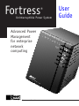
Fortress
®
Uninterruptible Power System
Advanced Power
Management
for enterprise
network
computing
The Answer in Power Protection
User
Guide
Contents
Introduction.................................................................................................................2
1. Getting to Know Your Fortress.............................................................................4
2. Startup .....................................................................................................................6
3. Lights and Display..................................................................................................9
3A. Lights..............................................................................................................9
3B. Display ..........................................................................................................11
4. Using the Keys ......................................................................................................12
4A. What the Keys Do ........................................................................................12
4B. Displaying the Input Voltage and Battery Charge Bar Graphs ....................12
5. Communicating with Fortress.............................................................................14
5A. CheckUPS Software .....................................................................................14
5B. Communication Modes.................................................................................14
5C. RS232 Communication Mode ......................................................................15
5D. Extended Signal Communication Mode ......................................................16
5E. Remote Shutdown.........................................................................................16
6. Alarms....................................................................................................................17
6A. Silencing Alarms ..........................................................................................17
6B. Reacting to Alarms .......................................................................................17
6C. Alarm Table ..................................................................................................18
7. Troubleshooting ....................................................................................................20
7A. Customer Support.........................................................................................20
7B. Troubleshooting Table ..................................................................................20
7C. Replacing the Fuse .......................................................................................22
7D. Replacing the Batteries.................................................................................22
7E. Changing the Fortress’ Sensitivity to Power Problems................................25
7F. Changing the Fortress’ Baud Rate ................................................................27
8. About Your Fortress.............................................................................................27
8A. General Specifications..................................................................................27
8B. 100-volt and 120-volt Specifications ...........................................................28
8C. 220/230/240-volt Specifications...................................................................29
8D. Runtime Table ..............................................................................................29
9. Warranty ...............................................................................................................30
Index...........................................................................................................................33
Best Power makes no claim on trade names of application products mentioned in this
publication. Best Power’s trademark ownership extends to its own products only. Best
Power reserves the right to change specifications without prior notice.
Listed models available:
FSS-0387A
© 1996-1997 Best Power. All rights reserved.
1
Introduction
Fortress provides complete, no-break power protection, including protection against brownouts,
high voltage, and surges. During a power outage, Fortress provides power from its battery.
Fortress uses its lights, two-digit display, and Morse Code alarms to keep you informed of the
UPS status.
If you have a question or problem, please call the nearest Best Power office. (See the list
on the next page.) You can also get more product information by visiting Best Power’s World
Wide Web site at http://www.bestpower.com.
SAVE THESE INSTRUCTIONS! THIS MANUAL CONTAINS IMPORTANT
INSTRUCTIONS FOR YOUR UPS.
The installation and use of this product must comply with all national, federal, state, municipal,
or local codes that apply. If you need help, please call the nearest Best Power office.
CAUTION
Whenever the UPS is on, there may be dangerous voltage present at the UPS outlets. This is
true because the UPS battery supplies power even if the UPS is not plugged into the wall
outlet. All UPS units contain dangerous voltages. Before maintenance, repair, or shipment,
all connections must be removed; the UPS must be completely switched off and unplugged
or disconnected. The power supply cord is intended to serve as the AC disconnect. The outlet must be near the equipment and easily
accessible.
In UPS models with an input plug, the UPS ground (earth) conductor carries the leakage
current from the loads in addition to any leakage current the UPS generates. This UPS
generates no more than 0.4 mA of leakage current. To limit the total leakage to 3.5 mA, the
load leakage current must be limited to 3.1 mA. If you do not know the load leakage
current, replace the UPS power cord with a cord that uses a locking plug with a minimum
rating of 10 A (such as IEC 309). If you do not have a matching receptacle, consult an
electrician to install the proper receptacle. The three-wire receptacle that you plug the UPS
into must have a good (low-impedance) ground (protective earth) connection to provide a
safe path for leakage current.
2
North America
Best Power
P.O. Box 280
Necedah, WI 54646 U.S.A.
Telephone: 1-608-565-7200
Toll-Free: 1-800-356-5794 (U.S.A. and Canada)
FAX: 1-608-565-2221 (U.S. and Canada)
International FAX: 1-608-565-7675
Europe
Best Power Technology Limited
BEST House
Wykeham Industrial Estate
Moorside Road
Winchester
Hampshire
SO23 7RX
ENGLAND
Telephone: (44) 1962-844414
Toll-free: 0800 378444
FAX: (44) 1962-841846
Worldwide Service
P.O. Box 11
Necedah, Wisconsin 54646 U.S.A.
Telephone: 1-800-356-5737 (U.S.A. and Canada)
or 1-608-565-2100
Best Power Technology GmbH
Am Weichselgarten 23
D-91058 Erlangen
GERMANY
Telephone: +(49)9131/77700
Toll-Free: 0130/84/7712 (in Germany)
FAX: +(49)9131/7770-444
Latin America
Best Power Technology Mexico, S.A. de C.V.
Golfo de Riga, 34
Colonia Tacuba
Mexico D.F. 11410
MEXICO
Telephone: (52)(5) 399-0369
FAX: (52)(5) 399-1320
Borri Elettronica Industriale Srl
Via dei Lavoratori, 124
20092 CINISELLO BALSAMO (Mi)
Milan, ITALY
Telephone: (39) 2-6600661-2
FAX: (39) 2-6122481
Asia
Best Power Technology Pte. Ltd.
30 Prinsep St. #07-00
LKN Prinsep House
SINGAPORE 188647
Telephone: (65) 430 6168
FAX: (65) 430 6170
Best Power Technology AG
Limmatstrasse 12
8957 Spreitenbach
SWITZERLAND
Telephone: (41)056/418-30-30
FAX: 056/418-30-33
Australia
Sola Australia Ltd.
13 Healey Road
Dandenong Victoria 3175
AUSTRALIA
Telephone: 61-3-9706-5022
FAX: 61-3-9794-9150
Best Power Technology sarl (PARIS)
Zone de Fret 5-SOGARIS
14 Rue de la Belle Borne
B.P. 10673/Tremblay en France
95725 ROISSY CDG CEDEX, FRANCE
Telephone: (33)1 48 62 50 42
FAX: (33) 1 48 62 49 96
3
1. Getting to Know Your Fortress
Make sure you have the following:
G Fortress UPS
G For all models except 220/230/240-volt IEC* models, UPS Power Cord
G For IEC* models, Equipment Cord and Plug
G CheckUPS® Software Package and Interface Cable
* The drawings on the next page will help you identify your model.
If the UPS has been damaged during shipping, call your vendor immediately. If you plan to store
the UPS, follow these guidelines:
•Charge the batteries right away.
When you first unpack the UPS, plug it in and press
to start the UPS. (As it starts, the
display will show “On.”) Leave the UPS on for 24 hours to charge the batteries completely.
Shut down the UPS by pressing and holding the
key; then, unplug the UPS and store it.
•Check the temperature.
Store the UPS between 0° and 40° Celsius (32° and 104° Fahrenheit). If you store the UPS
above 25° Celsius (77° Fahrenheit), battery life will be shorter.
•Recharge the batteries.
Every six months, charge the batteries again. If you store the UPS at temperatures above 25°
Celsius (77° Fahrenheit), charge the batteries more often.
Model Number
Display
On/Off Key and Line Light
Battery Light
Alarm Light
Scroll Key
4
Back View of LI 520 and 720 Models
100-volt and 120-volt Models
220/230/240-volt
IEC Models
220/230/240-volt
Australian Models
2
2
2
3
4
3
4
3
4
1
1
1
6
5
5
4
3
2
1
1 = Outlets
3 = Inlet (Connect Power Cord Here)
5 = DIP switches
5
4
3
2
1
4
3
2
1
2 = Fuse Drawer
4 = DB9 Communication Port
6 = Site Wiring Fault Light (120-volt Models
Only)
Back View of LI 1020 and 1420 Models
100-volt and 120-volt Models
1
220/230/240-volt
IEC Models
1
4
2
220/230/240-volt
Australian Models
4
2
3
2
3
3
4
3
2
1
4
1
5
4
3
2
1
1 = Outlets
3 = Inlet (Connect Power Cord Here)
5 = DIP switches
5
4
3
2
1
5
2 = Fuse Drawer
4 = DB9 Communication Port
6 = Site Wiring Fault Light (120-volt Models
Only)
5
2. Startup
1
Place the UPS near the equipment it will protect. Do not put the
UPS near a source of heat. Do not block the UPS’
ventilation holes.
2
See page 5 to decide whether your UPS is a 100-volt or 120-volt model, a 220/230/240volt IEC model, or a 220/230/240-volt Australian model.
All models except IEC models: Plug
the cord that came with your UPS into
the UPS as shown. Then, plug the UPS
into your wall outlet. (Note for 120-volt
models: if the “Site Wiring Fault” light
shown is on, see Section 3A.)
IEC Models:
I) The computer (or other equipment)
that you want to protect should have a
power cord that you can disconnect or
“unplug” as shown. Disconnect this cord
so you can use it for the UPS. If the cord
is permanently attached to the equipment
you want to protect, order a UPS power
cord from Best Power or buy a cord that
will plug into the UPS’ IEC 320 inlet
and your wall outlet. II) Plug the cord
into the UPS as shown.
3
I
Now, press the
key to start the UPS. The display should show
“On,” then the percent of the UPS’ power that is being used. (This
may show a small number now.) The green light (on the key) should
be on. If the red Alarm light is on and the display shows a two-letter
alarm message, go to the alarm section on page 17; if there is
another problem, go to the troubleshooting section on page 20. (If
you need to shut the UPS off, press and hold the
key.)
CAUTION
The UPS outlets now have power.
6
II
7
4
The battery charges automatically whenever the green
light is
on. To make sure the UPS’ batteries can supply power, let the
batteries charge for at least 10 hours, especially if you have stored
the UPS. To check the battery charge, see Section 4B.
5
To protect your equipment, turn it off and plug it into the
outlets on the back of the UPS.
IEC models only: You received a cord you can use to connect
your equipment to the UPS. If you cannot connect this cord to
the equipment you want to protect, an electrician can wire the
plug you received to the equipment’s power cord.
6
Switch on the equipment plugged into the UPS, one at a time. If
the display shows “OL” and the Alarm light comes on, your
equipment needs more power than the UPS can supply. Turn off
the UPS (if it has not shut itself down) and disconnect the least
important equipment. Then, restart the UPS. If the display still
shows “OL,” turn off more equipment until the alarm stops and
the display shows the percent load (99 or below).
7
The UPS includes a CheckUPS software package that monitors
power conditions; during a long power outage, CheckUPS
automatically shuts down a computer system connected to your
UPS just before the UPS runs out of battery time. CheckUPS
also provides basic UPS monitoring and control. Find the
interface cable that came with the software package. Plug the
end of the cable marked “UPS” into the port on the back of the
UPS as shown, and tighten the screws on the top and bottom of
the port. Then, connect the other end of the cable to the
computer system that the UPS is protecting.
7
71
8
If the UPS will protect a computer that uses Windows 95, shut the computer down and
insert the CheckUPS CD. Then, restart the computer. Follow the instructions that came
with your CheckUPS software package to get started; then, use the online instructions to
install CheckUPS.
If the UPS will protect a computer that is NOT using Windows 95, start the
computer system. Follow the instructions in the CheckUPS software package to load and
start CheckUPS. Once you have done this, you can use the online instructions to learn to
use CheckUPS.
9
Remember to fill out the Warranty registration card and return it to Best Power. This card
registers your warranty and helps Best Power provide better service.
You have finished starting the UPS. To learn more about the UPS front panel lights and
keys, please read on.
Protecting Telephone and Data Lines
To protect telephone or data lines, you can use a Best Power SpikeFree surge suppressor. SpikeFree
MAX modules connect to the TVSS (Transient Voltage Surge Suppression) ground terminal on the
back of the Fortress. This provides a common ground for the power lines and your data or
telephone lines. This connection is the key to the best surge protection from your SpikeFree MAX
modules. If you would like to order a SpikeFree, please call the nearest Best Power office for
information on the modules that are available for your equipment.
Note: If your SpikeFree modules are already connected to a SpikeFree Base, you do not need to
connect them to the Fortress TVSS ground. The Base unit provides the grounding the
modules need.
To connect the SpikeFree module to your Fortress, follow these steps:
1. Packed with your SpikeFree module, you will find a kit with the following parts:
• a metal clip
• a wire with a ring connector on each end
• two Phillips screws
• a star washer
• a nut
• a brass bushing
You will not be using the larger Phillips screw and the brass
Phillips
bushing.
Screwdriver
2. Figure 1 shows how you will connect the smaller screw and the wire,
washer, and nut to the metal clip. Start by sliding the smaller Phillips
screw into the clip, and let the bottom of the screw fall through the hole
in the clip. The screw head should rest inside the clip as shown in
Figure 1.
8
Metal Clip
Ring
Connector
Figure 1
Star
Washer
Nut
Screw
3. Now, use a Phillips screwdriver to pry the clip open as shown in
Figure 1. Insert the screwdriver into the screw head.
4. Next, find the wire with ring connectors on each end. Attach one ring
connector to the screw as shown in Figure 1. Place the washer on the
screw under the ring connector, and use the nut to fasten the
connection. Remove the Phillips screwdriver from the clip.
Figure 2
5. Now, turn your SpikeFree module upside-down. Notice that there are
two slots in the bottom of the surge protector — one on the side of the
protector that curves in, and the other on the side that curves out. See
Figure 2. Insert the metal clip into the slot on the side of the module
that curves out. (Using this slot will make the clip easier to remove
later.)
Note: If you have two or more SpikeFree modules connected
together, attach the metal clip to the end module as shown
in Figure 3.
6. Use a Phillips screwdriver to remove
the ground screw from the back of the
Fortress. (See Figure 4 to find the
ground screw.)
Figure 3
LI 1020 and 1420
LI 520 and 720
TVSS Ground
Connection
7. Place the ring connector on the ground
screw and reattach the screw to the
Fortress as shown.
TVSS Ground
Connection
Figure 4
3. Lights and Display
Fortress uses its lights and its display to let you know what it is doing. As you use the UPS, the
lights and display may change. This section shows you how to understand the UPS front panel.
3A. Lights
The UPS has three lights on the front panel: the green
light, the yellow
light, and the red
light. 120-volt models also have a small red Site Wiring Fault light above the DIP switches
on the back panel. The paragraphs below explain what each light means.
9
When this light is on (steady, not blinking), the UPS is using the utility power it
receives when you plug it in. The UPS conditions this power and protects your
equipment from power problems. The display shows the percent of the UPS’ power
that your equipment is using.
If the green light is blinking while the yellow light is on, utility power is available, but the UPS is
not using it because of high or low voltage or other power problems. If the input power problem
continues, the UPS will continue to run on battery power until it uses up its battery backup time.
To adjust the UPS’ sensitivity to utility power problems, see Section 7E.
When this light is on (steady, not blinking), the UPS is using its batteries to
provide power to your equipment. This happens during a power outage or when there
is a severe problem in the power your UPS is receiving. The display flashes the
number of minutes the UPS can provide battery power (backup time or runtime), and
the UPS beeps regularly.
If this light is on while the green light is blinking, the UPS is running on battery power because
of a problem in the input power, not because of a power outage. The UPS must run on battery
power to provide the best power to your equipment. To adjust the UPS’ sensitivity to these power
problems, see Section 7E.
When this light is blinking, the UPS is performing a battery test to make sure it can provide
enough backup time. The UPS does the battery test automatically every 30 days; you can also
start a test by pressing and holding the
key. (See Section 4A.)
When this light is on or flashing, the UPS is warning you that something is wrong.
The UPS helps you identify the source of the problem in two ways:
1) by flashing a two-letter alarm message, and
2) by sounding the Morse Code for an alarm letter.
The Alarm section on page 17 will help you identify the alarm using either the alarm message or
the Morse Code. To silence the alarm, press and hold
. The display will show “Sh” briefly, and
the red light will be steady (not blinking or flashing).
120-volt models have a light on the back panel in the lower right corner.
If this light is on, the outlet the UPS is plugged into needs repair. Plug
the UPS into another outlet and call an electrician to repair the faulty
outlet.
Site Wiring
Fault Light
4
3
2
1
10
3B. Display
The UPS uses the two-character display above the lights to show you the unit’s status. If the red
light is on, the UPS flashes a two-letter alarm message. Press the
key to silence the alarm;
then, find the alarm message in Section 6C to identify the alarm. If the display shows a “b” or
“U” (V) with a line after it, the display is showing a bar graph of the battery charge or input voltage. See Section 4C to display and interpret the bar graphs. The table below explains the other
displays you may see on the front panel.
71
If the green
light is on, the display is showing the percent of the UPS’ power your
equipment is using. If your equipment requires more than 100% of the power your model
can provide, the UPS will sound an Overload alarm. (See Section 6C.)
15
If the yellow
light is on, the display is showing the estimated battery backup time left
— in other words, the number of minutes the UPS can continue running on battery power
until it shuts down.
--
The UPS shows this display when you have shut it down using the off or shutdown
command. You can send this command if you have connected a computer to the UPS’
RS232 port and if the UPS is in RS232 mode. For more information, call Best Power for
document FTS 502.
The UPS displays “bt” when you have started a battery test by pressing and holding the
key. (See Section 4A.)This test determines whether the UPS is ready to run on battery
power. If the UPS fails the test, it sounds an “rb” (replace battery) alarm; see Section 6C.
Once the test starts, you can cancel it by pressing and holding the
key; the display will
show “tc” for “test cancel.”
L?
Some alarms cause the UPS to shut down; the UPS also shuts down when you use the off or
shutdown commands. (See the - - display above.) Once the UPS has shut down, you can
restart it using the
key on the front panel. However, if utility power is not available from
the outlet the UPS is plugged into, the UPS will not restart, and it will show this display.
OF
The UPS displays “OF” briefly when you turn the unit off.
The UPS displays “On” briefly when you turn the unit on.
When you silence an alarm, the UPS displays “Sh” briefly. You can silence an alarm by
pressing the
key. Once you silence the alarm, the red light will be steady instead of
flashing.
The UPS shows this display when you cancel a battery test. See the “bt” display above.
Normally, you can start a battery test by pressing and holding the
key. If the UPS cannot
do this test because the battery power is low, the display will show “t?.”
“Un” stands for “unsilence.” When you silence an alarm, the UPS shows the “Sh” display
shown above. If you want to hear the alarm again, you can press the
key; the UPS will
sound the alarm and show “Un” briefly on the display.
11
4. Using the Keys
4A. What the Keys Do
On/Off Key:
Pressing this key turns the UPS on or off. When you turn the unit off, you
must hold the key briefly; the display will show “OF” before the unit shuts
down.
If the UPS shuts itself down because of an alarm, or if you shut the UPS down using a
command or DB9 contact, you can press this key to restart the UPS. Utility power must be
available at the outlet the UPS is plugged into before the UPS can restart. (See Sections
5C and 5D for information on contacts. For information on sending commands from a
terminal or computer, call Best Power.)
Scroll Key (Silence, Display, and Test):
Pressing this key briefly displays the input voltage bar graph. (See Section
4B.) Pressing the key once more displays the battery charge bar graph.
Pressing the key briefly one more time switches the UPS back to the normal
display.
If the UPS is sounding an alarm, pressing and holding this key silences the Morse Code
alarm. The display shows “Sh” when you do this. If you need to hear the alarm again, press
this key again; the display will show “Un” for “unsilence.”
If the UPS is not sounding an alarm, pressing and holding this key starts a system test; the
display will show “bt” briefly for “battery test.” The test determines whether the UPS is
ready to run on battery power. (The UPS does this test automatically every 30 days.) If the
UPS fails the test, it sounds an “rb” alarm. (See Section 6C.) Once the test starts, you can
cancel it by pressing and holding this key; the display will show “tc” for “test cancel.” If
the UPS cannot do the battery test because battery power is low, the display will show
“t?.”
4B. Displaying the Input Voltage and Battery Charge Bar
Graphs
Displaying the Input Voltage Bar Graph:
The input voltage bar graph shows you whether the voltage coming into the UPS
is normal, high, or low. This information can help you (or a technician) identify
problems in your input power.
12
To display this bar graph, press once. This display shows a “V” on the left and a line on the
right. The line on the right is a bar graph that shows the level of the voltage available at your
wall outlet and how the UPS is using this voltage. Here is what the graph means:
The input voltage is too low, so the UPS is boosting the voltage before providing
output to your equipment.
The input voltage is normal. The UPS is conditioning the power from your input
voltage before providing output to your equipment.
The input voltage is too high, so the UPS is in “buck” mode. In this mode, the UPS
reduces the voltage before providing output to your equipment.
To switch back to the normal display, press
briefly twice. The first time you press this key,
the display will change to the Battery Charge bar graph. The second time you press the key, the
UPS will switch back to the normal display.
Displaying the Battery Charge Bar Graph:
The Battery Charge bar graph shows you how much the batteries are charged. To display this bar
graph, press to display the input voltage bar graph first; then, press once more to display the
battery charge bar graph. This display shows a “b” on the left and a line on the right. The line on
the right shows the battery charge. Here is what the graph means:
The battery charge is very low. If there is a power outage, the UPS will only run on
battery power for a short time before shutting down. If the UPS is receiving input
voltage from the wall outlet, it is charging its batteries.
The batteries are partly charged. If there is a power outage, the UPS can operate on
battery power for a short time. If the UPS is receiving input voltage from the wall
outlet, it is charging its batteries.
The batteries are fully charged (or close to being fully charged). If there is a power
outage, the UPS should be able to provide the full battery backup time (runtime) for the
equipment it is protecting. If the UPS is receiving input voltage from the wall outlet, it
is keeping the batteries charged.
To change back to the normal display, press the
key briefly.
Note: When the UPS switches from battery power operation to normal (AC line) operation, the
battery charge bar graph may not be accurate for a few seconds. The UPS will
correct the graph after a few seconds.
13
5. Communicating with Fortress
5A. CheckUPS Software
Your Fortress includes an interface cable and a CheckUPS software package for easy communication
and power monitoring. See the instructions that came with your software package to install
CheckUPS software and start the online instructions.
CheckUPS monitors power conditions and lets you display them on your computer screen. When
there is a long power outage and the UPS is running out of battery time, CheckUPS will ask the
users on your system to log out. Then, CheckUPS will do an orderly shutdown of the system
before the UPS shuts down. See the online CheckUPS manual for more information. CheckUPS
also lets you monitor power problems and display information about the UPS. The CheckUPS
CDROM Suite you received supports Novell NetWare, Windows (3.x, 95, and NT), UNIX and
compatible systems, OS/2, and DOS. For the latest information on CheckUPS or automatic shutdown kits, call 1-800-356-5794 (U.S. and Canada), 1-608-565-7200, or the nearest Best Power
office.
Even if you are not using CheckUPS, you can communicate with the UPS using a dumb terminal
or a terminal emulation program (such as CROSSTALK® or ProComm™); see Sections 5B and
5C. (Windows® includes a terminal program; see the icon labeled “Terminal.”)
5B. Communication Modes
The UPS has two communication modes:
RS232 Communication Mode
Your UPS is set to this mode when you receive it. This is the communication mode used
by CheckUPS software; see Section 5A. If you decide not to use CheckUPS, you can use
this mode to issue commands to the UPS and to display UPS settings and power
conditions. See Section 5C for pin information; if you would like more information on
two-way communication, commands, and UPS settings, call Best Power to request
document FTS 502.
Extended Signal Mode
In this mode, additional signal contacts are available for Remote Shutdown and On Battery
Status. You may decide to use this mode if you have your own UPS
monitoring software and you do not plan to use CheckUPS. Two-way
communication is not possible in this mode — you cannot send commands or
display or change parameters. See Section 5D.
14
RS232
Mode
Changing Communication Modes
1.
2.
Find the DIP switches on the back of the UPS (see the drawings
below); then, find DIP switch 4 (see the drawing to the right).
Use a nonmetal object such as a toothpick to move DIP switch 4
from one side to the other; if the UPS is on, it will beep. Make sure
you do not accidentally change the position of another DIP switch.
Extended
Signal Mode
4
3
2
1
LI 1020 and 1420
LI 520 and 720
DIP Switches
DIP Switches
5C. RS232 Communication Mode
When the UPS is in the RS232 communication mode, the pins at the DB9 communication port
perform these functions:
Pin 1: RS232 Receive Data. Receives incoming RS232 communication data.
Pin 2: RS232 Transmit Data. Sends outgoing RS232 communication data.
Pin 3: Normally Open On Battery Contact. A normally open contact that closes 15 seconds
after the UPS switches to battery power.
Pin 4: Common. The signal ground for all signal pins.
Pin 5: Normally Open Low Battery Alarm Contact. A normally open contact
that closes during a Low Battery, Near Low Battery, or Low Runtime
alarm. This tells CheckUPS and other shutdown software when to start a
computer shutdown. (You can enable this contact for other alarms; for
more information, call Best Power for document FTS 502.)
Pin 6: Plug and Play Sense for Windows 95.
Pin 7: Remote Shutdown. Shorting this pin to common turns the UPS off.
Pin 8: Unregulated +12 V isolated source.
Pin 9: Not Used.
Contacts consist of open collector circuits capable of switching up to +40 VDC 50 mA resistive
load. If you would like to communicate with the UPS without using CheckUPS software, call
Best Power to request document FTS 502.
15
5D. Extended Signal Communication Mode
In this mode, the UPS communication port acts as a source for signals for your computer software
or other external equipment. This mode does not allow for two-way RS232
communication. The functions of pins 1 and 2 change in this mode, but pins 3-9 have the same
functions. Contacts consist of open collector circuits capable of switching up to +40 VDC 50 mA
resistive load.
Pin 1: Remote Shutdown. If the UPS is using battery power and a +12-volt DC signal is applied
to this pin for 5 seconds, the UPS will shut down 30 seconds later. When the power outage
ends, the UPS will automatically restart. Signal and shutdown times and automatic restart
are programmable; see document FTS 502 for more information.
Pin 2: On Battery Status. When the UPS is using battery power, this pin produces a +12-volt DC
(RS232-level) signal.
Pin 3: Normally Open On Battery Contact. A normally open contact that closes 15
seconds after the UPS switches to battery power.
Pin 4: Common. The signal ground for all signal pins.
Pin 5: Normally Open Low Battery Alarm Contact. A normally open
contact that closes during a Low Battery, Near Low Battery, or Low
Runtime alarm. This pin tells CheckUPS and other shutdown
software when to start a computer shutdown. (You can enable this contact
for other alarms; for more information, call Best Power for document FTS
502.)
Pin 6: Plug and Play Sense for Windows 95.
Pin 7: Remote Shutdown. Shorting this pin to common turns the UPS off.
Pin 8: Unregulated +12 V isolated source.
Pin 9: Not Used.
5E. Remote Shutdown
You can set up the UPS for remote shutdown using contacts at the DB9 port. These contacts let
you shut down the UPS completely; it will not supply power to the equipment it protects. Your
remote shutdown switch must have a set of contacts that can short pin 7 on the UPS
communication port to pin 4 (common). This connection will shut down the UPS’ output power to
the protected equipment. When this happens, the UPS will sound alarm “Sd” for “shutdown”
(Morse code alarm H). When you are ready to restart the UPS, the shutdown switch must remove
the connection to pin 7 on the UPS communication port. Then, you can press the
key to
restart the UPS. You can change the type of Remote Shutdown signal that the UPS responds to and
how quickly it responds. Call Best Power’s Worldwide Service for more information.
16
6. Alarms
Sometimes Fortress detects a problem and warns you about it by sounding an alarm. When this
happens, the UPS lights the red
(Alarm) light, flashes a two-letter alarm
message on the display, and sounds a Morse code alarm.
6A. Silencing Alarms
OL
Press this
key to
silence
alarms.
To silence an alarm, press the bottom (arrow) key on the front
panel. The Morse-code alarm will stop, and the display will
show “Sh” for a short time. The red Alarm light will stop
blinking, but it will stay on unless you have solved the
problem that caused the alarm. The display will still show the
alarm message. Remember: Silencing the alarm does not
solve the problem that caused it. Go on to find out how to
react to the alarm.
If the alarm is still active and you would like to hear the alarm again, press the bottom key again.
The display will show “Un” for “unsilence,” and the unit will begin sounding the Morse Code
for the alarm.
6B. Reacting to Alarms
The UPS display switches between the normal display and an alarm message. Go to the Alarm
Table on the next few pages and find your alarm message in the left column. Follow the
instructions for that alarm. The UPS also sounds the alarm letter code in Morse Code; if you are
not near the UPS, you can use the Morse code and the table on the next few pages to identify the
alarm.
Example: If the display shows “OL” as shown, read the information next to “OL” in the Alarm
Table. The table shows that this is an overload alarm, and you must disconnect some of
the equipment plugged into your UPS.
17
6C. Alarm Table
Alarm
Message
Alarm
(Morse)
Code
What the Alarm Means
What to Do
CL
I
(• •)
Calibration Lost. This can happen when
you replace the batteries if the UPS is
off and you wait too long to install the
new batteries. The alarm means the UPS
has lost any changes you have made to
parameters via two-way communication;
it may also mean the UPS has lost
internal factory settings.
Call Best Power. If you have changed any
parameter values since you received the
UPS (including time and date), you must
set these parameters again.
FA
F
(• • – •)
Fan Malfunction. The fan in the LI 1420 Call Best Power’s Worldwide Service or
is not operating. If the problem
the nearest Best Power office.
continues, the UPS will shut down.
Hb
C
(– • – •)
High Battery. Battery voltage is high,
which could mean there are battery or
charger problems. When the UPS
sounds this alarm, it cannot charge the
batteries.
Call Best Power’s Worldwide Service or
the nearest Best Power office.
Lb
A
(• –)
Low Battery. The UPS has run on
battery power for a while and the
batteries are low, so the UPS has shut
down. The alarm will stay on until the
power outage (or power problem) ends
and the UPS can restart using AC input
power.
Shut down any equipment connected to
the UPS. After the power outage (or
power problem) ends, the UPS will restart
automatically; if you do not want it to do
this, call Best Power for help. When the
UPS restarts, you can start the equipment
connected to the UPS. Battery backup
time (runtime) will be low until the UPS
recharges its batteries.
Lo
B
(– • • •)
Near Low Battery. The UPS has run on
battery power for a while and the
batteries are near a Low Battery
shutdown. (See alarm “Lb.”) If the UPS
continues to run on battery, it will soon
shut down and sound a Low Battery
(Lb) alarm. If the UPS switches back to
AC input power before the Lb shutdown, it will recharge its batteries; the
“Lo” alarm will stop as batteries
recharge.
To prepare for the Low Battery
shutdown, switch off the equipment
connected to the UPS. If the power outage
ends before the “Lb” shutdown, you can
restart your equipment. If not, the UPS
will restart automatically when the power
outage or power problem ends. Restart the
equipment connected to the UPS. Battery
time will be low until the UPS recharges
its batteries.
18
Alarm
Message
Alarm What the Alarm Means
(Morse)
Code
What to Do
Lr
D
(– • •)
Low Runtime. The UPS has been
running on battery power; the batteries
are discharging, so the UPS can only
operate on battery for a short time before
shutting down. The alarm starts when the
UPS has three minutes of battery backup
time left; see the display for the
estimated battery time (runtime).
If you are using CheckUPs software,
CheckUPS will warn users to log out of the
system and will begin an automatic
shutdown. If you are not using CheckUPS,
switch off the equipment connected to the
UPS and switch off the UPS. When the
power outage ends, the UPS will restart
automatically, and you can restart the
equipment connected to the UPS. Battery
time will be low until the UPS recharges its
batteries.
LU
E
(•)
Low AC Output. The output voltage to
the loads is low, so the UPS shuts down.
Call Best Power’s Worldwide Service or the
nearest Best Power office.
OL
G
(– – •)
Output Overload. Your equipment needs a
larger UPS because it requires more than
100% of your model’s power. The display
shows the alarm number and then what
percent of the UPS’ power you are using.
Depending on the amount of overload,
the UPS may shut down soon.
• If the UPS is still running, decide which
equipment is least important, and shut off
one piece of equipment plugged into the
UPS. If the alarm does not stop, shut off
more equipment until the Morse code alarm
stops and the red light turns off. Then,
unplug the equipment you have shut off; for
now, you can plug it into the nearest wall
outlet.
• If the UPS has shut down, disconnect the
least important equipment from the UPS
and restart the UPS by pressing
. Then,
restart your equipment. If the UPS sounds
an overload alarm again, you must
disconnect more equipment.
rb
K
(– • –)
Replace Battery. The UPS batteries need
replacing; they have failed the system
test. (The UPS does this test
automatically every 30 days; you can also
start the test by pressing the bottom key.)
Call the nearest Best Power office
immediately to order new batteries. Then,
follow the instructions in Section 7D to
replace the batteries.
Sd
H
(• • • •)
External shutdown. A user started a
remote shutdown. (See Section 5E.)
To restart the UPS, reset the remote
shutdown switch and press
on the
UPS. The display will show “On,” and the
UPS will restart.
Ut
J
User Test Alarm. A user started an alarm
(• – – –) test by sending the alarmtest command
from a computer or terminal. (For more
information on commands, call Best
Power.)
19
To cancel the User Test alarm, send the
alarmtest cancel command from a
computer or terminal. (For more
information on commands, call Best
Power for document FTS 502.)
7. Troubleshooting
7A. Customer Support
The troubleshooting table in Section 7B provides solutions for some UPS problems. If you need
more help, please call the nearest Best Power office or Best Power’s Worldwide Service. (See
the beginning of this manual; you can reach Worldwide Service at 1-800-356-5737 in the
U.S. and Canada or at 1-608-565-2100.) Please have your UPS model number and serial
number when you call. The model number is printed on the UPS front panel; the serial number
is on the back panel label. Best Power’s service technicians have in-depth knowledge of the UPS
and power problems.
Best Power may tell you the UPS must be returned. If this happens, Best Power will give you a
Return Material Authorization (RMA) number. Do not return the UPS without contacting Best
Power first. If you return a UPS, please use the original packing material in which your
unit was shipped to you. If you do not use the original packing material and your unit is
damaged during shipping, you will be responsible for repair charges. Our freight carriers will not
accept responsibility for damage to units not packed in Best Power packing. If you have
discarded the original packing material, call the nearest Best Power office; we will send you new
packing material at no charge.
7B. Troubleshooting Table
If the UPS is sounding an alarm, see Section 6. For other problems, see the table on the next two
pages.
Problem
Possible Reason for Problem
The UPS always runs
on battery power (the
yellow Battery light is
always on).
• The detachable cord may not • Make sure the cord is
be completely plugged into the completely plugged into the UPS
back of the UPS or the wall
and the wall outlet.
outlet.
• The wall outlet may not be
providing power.
What to Do
• Try a different outlet.
• The fuse may need replacing. • Replace the fuse. (See Section
7C.)
• The input power available at
your outlet may be unstable.
• Try switching the DIP
switches that adjust Line
Sensitivity and the Input Voltage
Range. (See Section 7E.)
20
Problem
Possible Reason for Problem
What to Do
The UPS will not • The UPS may not be in the correct • See Section 5B for a description of the
communication mode.
modes and how to change the modes.
communicate.
• The UPS baud (communication)
rate (normally 1200) may not match
your computer’s baud rate.
• Change the baud rate of your computer
or terminal. To change the UPS’ baud
rate, see Section 7F.
• Extensions with incorrect pinouts
• Remove any extension cables. Use the
may have been added to the
cable Best Power provided to connect
interface cable Best Power provided. the UPS directly to the computer.
• The Best Power-supplied cable
may have been plugged in
incorrectly.
• Make sure the end of the cable marked
“UPS” is plugged into the UPS, and the
other end is plugged into the computer.
The green light is
blinking while
the yellow
Battery light is
on.
The input voltage the UPS is
receiving from your wall outlet is
either very high or very low, so the
UPS is running on battery power to
make sure your equipment receives
quality power.
The UPS will continue to run on battery
power until input voltage is normal or
until the UPS runs out of runtime and
sounds an “Lb” (Low Battery shutdown)
alarm. If the UPS runs on battery power
too often, try changing the UPS’
sensitivity to power problems. (See
Section 7E.)
The yellow light
is blinking.
The UPS is doing a system test to
make sure it can run on battery. The
unit does this test every 30 days; if it
finds a battery problem, it will sound
an “rb” alarm. You can also start this
test using the key.
Since this is a normal part of the UPS’
operation, you do not need to react to
this condition. If the UPS discovers a
problem, it will sound an alarm.
The UPS is
• The UPS may have shut down
because its batteries ran down
completely off
and will not start. during a long power outage.
• The UPS may have been
overloaded.
Shut down the equipment connected to
the UPS. Press the
key for a few
seconds. If the UPS does not start, leave
the UPS plugged in overnight. If the
UPS still does not start, call the nearest
Best Power office.
• There may be a UPS problem.
The UPS turns
itself off
immediately after
you start it.
The UPS’ batteries are completely
discharged, and utility (AC input)
power is not available to the UPS.
(The batteries may have been
discharged because the UPS was in
storage or because the UPS ran on
battery power for a long time.)
21
Make sure the UPS is plugged in, and
leave it plugged in overnight to recharge
the batteries. Then, restart the UPS.
Note: You cannot restart the UPS during
a power outage because it must have
utility power to operate and to recharge
the batteries.
7C. Replacing the Fuse
If you have any problems replacing the fuse, please call the nearest Best Power office. (See
the beginning of this manual.)
1. If you have never replaced the UPS fuse before, you can use the spare fuse in the fuse holder.
If you need a new fuse, you can order one by calling the nearest Best Power office; otherwise,
check the label on the back of the UPS for the fuse’s size and type. Make sure your new fuse
is the size and type shown on the UPS label.
2. Shut off all equipment plugged into the back of the UPS. Next, you must shut down the
UPS by pressing the
key on the front panel. Unplug the power cord from the back of
the UPS.
3. The drawing shows the 520 and 720 fuse holder. To find the
1020 or 1420 fuse holder, see page 5. To open the fuse holder,
push on the tab until the fuse holder pops out.
4. Pull the fuse holder out until you can see the fuse shown.
5. If you have not used the spare fuse yet, there will be two
fuses in the fuse holder. The used fuse is on the side with the
metal contacts. Remove this fuse from the fuse holder and put
the spare fuse (or a new fuse) in its place.
6. Push the fuse holder back in until it latches.
7. To test the UPS, plug it into the wall outlet. Press the
key on the front panel to restart the
UPS. Then, switch on the equipment plugged into your UPS. Battery backup time may be low
until the UPS recharges its batteries. If the UPS does not restart, call the nearest Best Power
office.
7D. Replacing the Batteries
Fortress’ batteries are user-replaceable and hot-swappable. This means that you can safely and
easily replace the batteries while the UPS is running. All you’ll need is a Phillips screwdriver.
Before you replace the batteries, make sure that you read the safety
information below.
NOTE: If you have a power outage while you are replacing the batteries, the UPS will not be
able to run on battery power, and your protected equipment will shut down.
22
CAUTION
1. The batteries used in the UPS and battery pack(s) can produce dangerous voltage and high
current. Therefore, the batteries may cause severe injury if their terminals contact a tool or
the UPS cabinet. Be very careful to avoid electrical shock and burns from contacting
terminals while you replace the batteries.
2. Batteries contain caustic acids and toxic materials and can rupture or leak if mistreated.
Remove rings and metal wristwatches or other jewelry. Do not carry metal objects in your
pockets; these objects could fall into the UPS.
3. Never allow any tool to contact both a battery terminal and the UPS cabinet or another
battery terminal. Do not lay tools or metal parts on top of batteries.
4. To ensure continued superior performance of your UPS and to maintain proper charger
operation, you must replace the UPS batteries with the same number and type of batteries.
These batteries must be the same type as the original batteries: valve-regulated, lowmaintenance. The replacement batteries should have the same voltage and ampere-hour rating
as the original batteries.
5. Assume that old batteries are fully charged. Use the same precautions you would use when
handling a new battery. Do not short battery terminals with a cable or tool! Batteries
contain lead. Many areas have regulations about disposing of used batteries. Please dispose
of old batteries properly. For help, please call the nearest Best Power office. DO NOT
dispose of batteries in a fire because the batteries could explode. Do not open or mutilate
batteries. Released electrolyte is harmful to the skin and eyes. It may be toxic.
LI 520 and LI 720
Make sure you have your unit’s model number and serial number. Then, call the nearest Best
Power office to order new batteries. Once you have the new batteries, follow the steps
below.
1. Turn the UPS on its side as shown. Make sure the arrow on the bottom panel is
pointing up.
2. Remove the screw (shown) from the bottom panel.
3. Once you have removed the screw, swing the panel out, away from the UPS.
23
THIS SIDE UP WHEN OPENING
DOOR TO REPLACE BATTERIES
Remove this screw
4. Find the red and black connector shown. This connects the batteries to the UPS. Disconnect
the connector to disconnect the batteries. Do not pull on the wires as you
disconnect the batteries; instead, pull on the connector.
Fortress has hot-swappable batteries. If the UPS is off for any reason during battery
replacement, make sure you connect the new batteries promptly once you have
disconnected the old batteries. This will help you avoid losing any parameter changes you
have made as well as some UPS settings. If the UPS loses parameter changes, it will sound
a “CL” (Calibration Lost) alarm when you restart it. If this alarm starts, see Section 6C.
Tab
CAUTION
Find the battery terminals that the cables are connected to. Make sure these
terminals do not contact any metal as you remove the batteries. Do not contact the
battery terminals with any tool or metal object.
5. Pull on the tab to slide the batteries out of the UPS. See page 23 for cautions about
battery disposal.
6. Your new batteries should already have the cables and the red and black connector attached.
Slide the new batteries in with the battery terminals up.
7. Reconnect the batteries’ red and black connector to the matching UPS connector, red to red,
black to black.
8. Swing the panel closed and reattach the screw to fasten it shut.
9. Set the UPS upright again.
24
LI 1020 and LI 1420
Make sure you have your unit’s model number and serial number. Then, call the nearest Best
Power office to order new batteries. Once you have the new batteries, follow these steps:
1. Find the battery drawer on the back of the UPS. Remove
the two screws in the drawer as shown. Then, pull the
drawer’s handle until it slides out of the UPS. The
drawer will stop moving just before it is out of the UPS.
Turn the drawer slightly to the left and pull it out the rest
of the way. Fortress has hot-swappable batteries. If
the UPS is off for any reason, install the new battery
drawer promptly once you have removed the old
drawer. This will help you avoid losing any parameter
changes you have made as well as some UPS settings.
If the UPS loses parameter changes, it will sound a
“CL” (Calibration Lost) alarm when you restart it. If
this alarm starts , see Section 6C.
2. Slide the new drawer you received completely into the
back of the UPS. (Turn the drawer slightly to the left as you put it in the UPS.)
3. Use the two screws you removed to fasten the new drawer to the UPS.
4. See page 23 for cautions about disposing of old batteries.
7E. Changing the Fortress’ Sensitivity to Power Problems
As shipped, your UPS is programmed to provide the best power protection possible. However, if
the voltage available to your UPS varies widely, or if it is unstable, you may need to adjust some
UPS settings to make the UPS less sensitive to power problems. Adjusting the settings is only
necessary if the power problems cause the UPS to run on
battery power often.
Input Voltage Range
As shipped, your UPS can accept a large amount of voltage variation without switching to
battery power. At the low end of this range, the UPS boosts the voltage before providing
output for your equipment. At the high end of this range, the UPS reduces the voltage before
providing output.
120-volt units can accept 88-149 VAC without switching to battery power.
220/230/240-volt units can accept 169-286 VAC without switching to battery power.
By changing a DIP switch position, you can set the UPS to accept even wider ranges:
120-volt units: 81-155 VAC.
220/230/240-volt units: 155-297 VAC.
25
Please note that if you change the DIP switch setting, the
Normal
output voltage range that your UPS provides to your equipment Range
is wider as well. To change the DIP switch setting, follow
these steps:
Wider
Range
4
1. Find the DIP switches on the back of the UPS. (See the
drawings below.) Then, find DIP switch 3.
3
2. Use a nonmetal object such as a toothpick to move DIP
switch 3 from one side to the other; if the UPS is on, it will
beep. Make sure you do not accidentally change the position of another DIP switch.
2
1
LI 1020 and 1420
LI 520 and 720
DIP Switches
DIP Switches
Sensitivity to “Glitches” in Input Power
The UPS is designed to protect your equipment from problems or “glitches” in input power.
If the glitches are very severe, the UPS may need to run on battery once in a while to protect
your equipment.
If the UPS must run on battery power often because of problems in your input power, you
may want to lower the UPS’ sensitivity to these problems to save battery power. To do this,
follow these steps:
1. Find the DIP switches on the back of the UPS. Then, find DIP
switch 2. (See the drawings above.)
2. Use a nonmetal object such as a toothpick to move DIP switch 2
from one side to the other; if the UPS is on, it will beep. Make
sure you do not accidentally change the
position of another DIP switch.
26
4
3
2
1
7F. Changing the Fortress’ Baud Rate
As shipped, your Fortress is set to communicate at a baud rate of 1200. If you want to use twoway communication, but your computer or terminal cannot communicate with the Fortress, make
sure the computer or terminal is also set to 1200 baud. If you want to change the Fortress’ baud
rate, you must establish two-way communication with the Fortress; for instructions, call Best
Power and request document FTS 502.
8. About Your Fortress
8A. General Specifications
Capacity
(VA, Watts)
Battery Voltage
Dimensions
Height:
Width:
Depth:
Weight
Audible Noise
LI 520
LI 720
LI 1020
LI 1420
520 VA,
340 Watts
720 VA,
470 Watts
1020 VA,
700 Watts
1420VA*,
975 Watts
*For 100-volt
models, 1200 VA.
24 VDC
24 VDC
36 VDC
48 VDC
6.5 in (165 mm)
5.5 in. (140 mm)
17 in. (435 mm)
6.5 in (165 mm) 9.25 in. (235 mm) 9.25 in. (235 mm)
5.5 in. (140 mm)
7 in. (180 mm)
7 in. (180 mm)
17 in. (435 mm) 17 in. (435 mm) 17 in. (435 mm)
30 lbs.
(13.6 kgs.)
30 lbs.
(13.6 kgs.)
45 lbs.
(20.4 kgs.)
55 lbs.
(25 kgs.)
40 dBA on line
40 dBA on line
44 dBA from
front on line,
48 dBA from
other sides on
line.
44 dBA from
front on line,
48 dBA from
other sides on
line.
27
Lightning and
Surge Suppression:
Passes ANSI/IEEE C62.41 Categories A and B2. Zero Surge
Clamping Response Time. 120-volt units are UL 1449 listed.
Surge Voltage
Let Through:
Lets through 0.7% of peak in ANSI/IEEE C62.41 1991 Category A
test.
Noise (RF) Isolation: Normal and common mode EMI/RFI suppression. Full-time
advanced multi-stage filter.
Efficiency:
95% on line.
Input Protection:
Fuse: See the label on the back of the UPS for size and type.
Section 7C describes how to replace the fuse.
Output Protection:
Automatic (current and overvoltage).
Output Waveform:
Sine-wave, 5% or less THD on inverter; same as line on AC line.
Output Frequency:
50 or 60 Hz ±0.5 Hz on battery. Frequency on line is the same as
line from 45 to 65 Hz.
Ventilation:
Air around UPS must be free of dust, chemicals, or other materials
that corrode or contaminate. Air must be free to move around the
UPS.
Battery:
Sealed, maintenance-free, valve-regulated operation. UL 924
recognized.
Battery Charger:
Temperature-compensated charger. Recharge time 10 hours
maximum to 85%.
Operating
Environment:
0° to 40° C (32° to 104° F). 0 to 95% relative humidity (without
condensation). 0-10,000 feet.
8B. 100-volt and 120-volt Specifications
Nominal Voltage:
100 VAC or 120 VAC.
Compliance:
100-volt models: UL listed.
120-volt models: UL listed, cUL, NOM certified, FCC.
Input Voltage Range: 100-volt models: 82-129 VAC, user-adjustable to 75- 134 VAC.
120-volt models: 88-149 VAC, user-adjustable to 81- 155 VAC.
Output Voltage
Range:
100-volt models: 93-113 VAC. For UJ models, the nominal output
voltage is 110 VAC.
120-volt models: 104-127 VAC.
Input Plug:
NEMA 5-15P.
Output Receptacles:
LI 520 and 720: Four NEMA 5-15R.
LI 1020 and 1420: Six NEMA 5-15R.
28
8C. 220/230/240-volt Specifications
Nominal Voltage:
230 VAC.
Compliance:
TÜV certified, CE certified.
Input Voltage Range:
169-286 VAC, user adjustable to 155-297 VAC.
Output Voltage Range:
200-243 VAC.
Inlet:
IEC 320
Output Receptacles (see
page 5):
LI 520 and 720:
Four IEC 320 or two Australian.
LI 1020 and 1420: Eight IEC 320 or three Australian.
8D. Runtime Table
Approximate Battery Time (in minutes)
Load
520
720
1020
1420
Typical Computer Load
50 VA
180
180
210
225
Typical ASCII terminal
75 VA
130
130
165
180
Macintosh SE/30
100 VA
100
100
135
150
IBM 3151 Display Station
150 VA
54
54
89
110
IBM PS/2 30 with VGA monitor
200 VA
40
40
74
94
Compaq Prolinea
250 VA
28
28
56
75
Typical Desktop PC
300 VA
22
22
38
56
IBM PS/2 95 with VGA monitor
350 VA
17
17
33
47
AT&T GIS 3350
400 VA
14
14
27
41
Dell Dimension with VGA monitor
450 VA
11
11
22
34
Compaq Proliant 2000
520 VA
8
8
17
27
Compaq Prosignia with VGA monitor
550 VA
—
7
16
25
DEC Station 5000-200
600 VA
—
6
13
21
DEC Alpha Series 3000 model 400 with VGA monitor
720 VA
—
5
11
17
IBM RS/6000 model 375 with 19-inch monitor
800 VA
—
—
8
14
Unisys U6000/35 (fully configured)
900 VA
—
—
7
12
AST Manhattan SMP with VGA monitor
1020 VA
—
—
5
10
2 Apple Quadra 900 with 21-inch monitor
1200 VA
—
—
—
7
HP 9000 series with 21-inch monitor
1420 VA
—
—
—
5
5 Zeos Pantera Pentiums
29
9. Warranty
LIMITED TWO YEAR WARRANTY
Standard Warranty For All Purchases
BEST POWER, a division of General Signal Power Systems, Inc. (hereinafter called BEST
POWER) warrants that each product sold by BEST POWER is compatible with existing
commercially available computer equipment with enclosed power supplies and is free from
defects in materials and workmanship under normal use and service. This warranty is applicable
only to the initial retail purchaser (PURCHASER), and is not transferable. The duration of this
warranty is two (2) years from the date of the first retail sale or the date of delivery to the
PURCHASER, whichever occurs first, subject to the following conditions.
If the PURCHASER discovers within the duration of this warranty a failure of the product to
perform compatibly with presently existing computer equipment or a defect in material or
workmanship, the PURCHASER must promptly notify BEST POWER in writing within the
duration of the warranty or not later than one month after expiration of the warranty. BEST
POWER’s obligation under this warranty is limited to the replacement or repair, subject to the
conditions specified below, of such product returned intact to BEST POWER which shall appear
to BEST POWER, upon inspection, to have been either incompatible or defective. Replacement
or repair will be made at BEST POWER’s Worldwide Service, Highway 80, Necedah, Wisconsin
54646, U.S.A. Such repair or replacement shall be at BEST POWER’s expense. This warranty
does not cover any taxes which may be due in connection with replacement or repair, nor any
installation, removal, transportation or postage costs. These expenses will be paid by
PURCHASER. If BEST POWER is unable to repair or replace the product to conform to this
warranty after a reasonable number of attempts, BEST POWER will refund the purchase price.
Remedies under this warranty are expressly limited to those specified above.
TO THE EXTENT ALLOWED BY LAW, BEST DISCLAIMS ALL OTHER WARRANTIES,
EXPRESS OR IMPLIED, INCLUDING, BUT NOT LIMITED TO, ANY IMPLIED
WARRANTIES OF MERCHANTABILITY OR FITNESS FOR A PARTICULAR PURPOSE,
AND ANY IMPLIED WARRANTY OF MERCHANTABILITY OR FITNESS FOR A
PARTICULAR PURPOSE ON THIS PRODUCT IS LIMITED IN DURATION TO THE
DURATION OF THIS WARRANTY. TO THE EXTENT ALLOWED BY LAW, BEST POWER
SHALL NOT BE LIABLE FOR ANY SPECIAL, INCIDENTAL, OR CONSEQUENTIAL
DAMAGES INCLUDING, BUT NOT LIMITED TO, LOSS OF PROFITS, INJURIES TO
PROPERTY, LOSS OF USE OF THE PRODUCT OR ANY ASSOCIATED EQUIPMENT.
Some states do not allow limitations on how long an implied warranty lasts, so that the above
limitation on duration of implied warranties may not apply to you. Some states do not allow the
exclusion or limitation of incidental or consequential damages, so the above limitation or
exclusion may not apply to you. This warranty gives you specific legal rights, and you may also
have other rights which vary from state to state. You are advised to consult applicable state laws.
30
No warranty is made with respect to other products sold by BEST POWER which do not bear
the name BEST POWER, and no recommendation of such other product shall imply or constitute
any warranty with respect to them. This warranty does not cover repair or replacement because
of damage from unreasonable use (for example only, damage from road hazard, accident, fire or
other casualty, misuse, negligence, or incorrect wiring) and any use or installation not in
conformance with instructions furnished by BEST POWER, or repairs or replacements needed
because of modifications or parts not authorized or supplied by BEST POWER.
LIMITED WARRANTY
Transient Voltage Surge Suppression Circuitry
(For U.S. and Canadian Purchasers Only)
BEST POWER, a division of General Signal Power Systems, Inc. (“BEST POWER”) hereby
warrants the transient voltage surge suppression circuitry in each FERRUPS®, FORTRESS®,
PATRIOT®, UNITY/I™, CITADEL®, or SPIKEFREE product (hereinafter called “Product”)
sold by it for installation in the United States of America and Canada to be free from defects in
material and workmanship under normal use and service for the lifetime of the Product,
beginning with the date of sale to the initial retail purchaser, subject to the following conditions.
This warranty is applicable only to the initial retail purchaser (hereinafter called PURCHASER),
is not transferable, and is limited to the following remedies:
1. The replacement or repair of the transient voltage surge suppression circuitry in each Product
that is returned intact to BEST POWER and which shall appear to BEST POWER upon
inspection to have been defective in material or workmanship or to have been damaged
through normal use;
2. The reimbursement to the PURCHASER of up to $25,000 per occurrence of documented
physical damage to specified computer equipment connected to a Product where such damage
could have been prevented by transient voltage surge suppression circuitry as detailed in
BEST POWER’s specification for the Product sold.
This warranty is made in addition to BEST POWER’s Limited Two Year Warranty.
This warranty does not include any taxes which may be due in connection with replacement or
repair nor any installation, transportation or postage costs. These expenses will be paid by
PURCHASER. Replacement or repair will be made at BEST POWER’s Worldwide Service,
Highway 80, Necedah, Wisconsin 54646, U.S.A.
This warranty does not cover repair or replacement because of damage from unreasonable use
(damage from road hazards, accident, fire or other casualty, misuse, negligence, incorrect wiring)
and any use or installation not in conformance with instructions furnished by BEST POWER, or
repairs or replacements needed because of modifications or parts not authorized or supplied by
BEST POWER.
31
This warranty is operable only upon the written acceptance by BEST POWER of an application
by the PURCHASER on BEST POWER’s standard form for the above warranty coverage for the
Product sold. In such application, the PURCHASER shall represent that the Product sold has
been properly installed and grounded in accordance with instructions received from BEST
POWER, and the PURCHASER shall also specify the computer equipment to which the Product
sold has been connected and the location of the computer equipment. This warranty will not
apply to any equipment not specified in the application by the PURCHASER as protected
equipment.
EXCEPT AS EXPRESSLY SET FORTH IN THIS WARRANTY AND BEST POWER’s
LIMITED TWO YEAR WARRANTY, BEST POWER MAKES NO OTHER WARRANTIES,
AND TO THE EXTENT ALLOWED BY LAW, BEST DISCLAIMS ALL OTHER
WARRANTIES, EXPRESS OR IMPLIED, INCLUDING, BUT NOT LIMITED TO, ANY
IMPLIED WARRANTIES OF MERCHANTABILITY OR FITNESS FOR A PARTICULAR
PURPOSE.
REMEDIES UNDER THIS WARRANTY ARE EXPRESSLY LIMITED TO THE REPAIR OR
REPLACEMENT OF PRODUCTS AND THE REIMBURSEMENT SPECIFIED ABOVE,
AND TO THE EXTENT ALLOWED BY LAW ANY CLAIMS FOR LOSS ARISING OUT OF
THE FAILURE OF PRODUCTS TO PERFORM FOR ANY PERIOD OF TIME, OR SPECIAL,
INDIRECT, INCIDENTAL OR CONSEQUENTIAL DAMAGES OR OTHER ECONOMIC
LOSS ARE EXPRESSLY EXCLUDED.
Some states do not allow limitations on how long an implied warranty lasts, so that the above
limitation on duration of implied warranties may not apply to you. Some states do not allow the
exclusion or limitation of incidental or consequential damages, so the above limitation or
exclusion may not apply to you. This warranty gives you specific legal rights, and you may also
have other rights which vary from state to state. You are advised to consult applicable state laws.
32
Index
Alarm Table ..........................................18-19
Alarms ..................................................17-19
Battery Backup Time...10, 11, 13, 18, 19, 29
Battery Replacement ............................22-25
Bar Graph .............................................12-13
Baud Rate.............................................21, 27
Cable ........................................................4, 7
Charge..........................................4. 7, 13, 28
CheckUPS......................................4, 7, 8, 14
CL ..............................................................18
Communication Modes ........................14-16
Customer Support ......................................20
Leakage Current...........................................2
Lo ...............................................................18
Lr................................................................19
LV (LU) .....................................................19
OL ..............................................................19
Pin Functions ........................................15-16
Power Cord....................................4, 5, 6, 20
Power Problems................................2, 25-26
rb ................................................................19
Remote Shutdown......................................16
RS232 Communication Mode ..............14-15
Runtime ...................... 10, 11, 13, 18, 19, 29
DIP switch .....................................15, 20, 26
Equipment Cord.......................................3, 6
Extended Signal Mode.........................14, 16
FA...............................................................18
Fuse......................................................20, 22
Glitches ......................................................26
Hb...............................................................18
Inlet ........................................................5, 29
Input Voltage Range...........20, 25-26, 28, 29
Sd ...............................................................19
Silence......................................10, 11, 12, 17
Site Wiring Fault ...............................5, 6, 10
Specifications........................................27-29
SpikeFree ..................................................8-9
Startup...................................................... 6-8
Temperature ...........................................4, 28
Troubleshooting....................................20-27
Troubleshooting Table ..........................20-21
Ut ...............................................................19
Ventilation..............................................6, 28
Keys............................................4, 12-13, 17
Warranty ...........................................8, 30-32
Lb ...............................................................18
33
120-volt Model s Only:
For Users in the United States Only
This equipment has been tested and found to comply with the limits for a Class A digital device, pursuant to Part 15 of the FCC rules. These limits are designed to provide reasonable protection against
harmful interference when the equipment is operated in a commercial environment. This equipment generates, uses, and can radiate radio frequency energy and, if not installed and used in accordance with the
instruction manual, may cause harmful interference to radio communications. Operation of this equipment in a residential area is likely to cause harmful interference in which case the user will be required
to correct the interference at his/her own expense.
For Users in Canada
This Class A interference causing equipment meets all requirements of the Canadian Interference
Causing Equipment Regulations ICES-003.
34