1
MPC-684 Programing tutorials
ACCEL
Last update May 24,2005
(MPC-684F)
This tutorial is an outline for MPC-684 programming.
Please see the “MPC-684 User’s manual” for details about products and commands.
For the newest information you should look at the web site http://www.accelmpc.co.jp
1
Index
MPC-684 family ............................................................................................................................................... 5
The feature of the MPC-684 ............................................................................................................................ 6
Program development environment................................................................................................................ 7
Hardware...................................................................................................................................................... 7
Software........................................................................................................................................................ 7
How to connect................................................................................................................................................. 8
Input commands ............................................................................................................................................ 10
I/O check..........................................................................................................................................................11
To check by command..................................................................................................................................11
Check by the “I/O checker” .........................................................................................................................11
How to input program ................................................................................................................................... 13
Multi statement.......................................................................................................................................... 13
Comment .................................................................................................................................................... 13
Label ........................................................................................................................................................... 13
Subroutine .................................................................................................................................................. 14
parameter of subroutine, return value...................................................................................................... 15
Edit of a program........................................................................................................................................... 16
LIST display ............................................................................................................................................... 16
Insert statement......................................................................................................................................... 17
Delete statement ........................................................................................................................................ 17
Other key operations.................................................................................................................................. 18
How to program save to the PC, load from the PC ...................................................................................... 19
Program save to the PC ............................................................................................................................. 19
Program load from the PC ......................................................................................................................... 20
Off line editing............................................................................................................................................ 20
Printing....................................................................................................................................................... 20
I/O control ...................................................................................................................................................... 21
Bit control ................................................................................................................................................... 21
Byte control ................................................................................................................................................ 21
Variable, Array variable, String variable, Memory I/O................................................................................ 22
Variable....................................................................................................................................................... 22
Local variable ............................................................................................................................................. 22
Array variable ............................................................................................................................................ 23
String array variable ................................................................................................................................. 23
2
Memory I/O................................................................................................................................................. 23
Calculation ..................................................................................................................................................... 24
Pulse generation ............................................................................................................................................ 25
Initial settings ............................................................................................................................................ 25
How to check operation by TEACHING MODE. ...................................................................................... 25
Setup of maximum high speed and acceleration. ..................................................................................... 26
Move to the origin (HOME) ....................................................................................................................... 27
Absolute coordinate movement.................................................................................................................. 28
Relative coordinate movement .................................................................................................................. 29
Continuous interpolation ........................................................................................................................... 30
PALET declaration..................................................................................................................................... 31
Conditional stop ......................................................................................................................................... 32
Multi-task....................................................................................................................................................... 33
The commands for multi-task.................................................................................................................... 33
RS-232 communication.................................................................................................................................. 34
Command for communication.................................................................................................................... 34
Debugging ...................................................................................................................................................... 35
Basic debugging (run/stop/check) .............................................................................................................. 35
Use the PRINT command .......................................................................................................................... 35
Subroutine execute..................................................................................................................................... 35
How to know the cause of machine stoppage............................................................................................ 36
How to read the programming port output log. ........................................................................................ 36
Special program ......................................................................................................................................... 37
Use touch panel ............................................................................................................................................. 38
When you use MBK-RS.............................................................................................................................. 38
When you use MBK-SH ............................................................................................................................. 39
Command List................................................................................................................................................ 40
I/O ............................................................................................................................................................... 40
MBK-SH/RS................................................................................................................................................ 40
MPG-314 Exclusive .................................................................................................................................... 40
MPG-3202 Exclusive .................................................................................................................................. 41
MPG-68K Compatible ................................................................................................................................ 41
RS-232 ........................................................................................................................................................ 42
Calendar ..................................................................................................................................................... 42
Floating Point Operation ........................................................................................................................... 43
System ........................................................................................................................................................ 43
3
Timer........................................................................................................................................................... 43
Task Operation ........................................................................................................................................... 43
Debug.......................................................................................................................................................... 43
Bus Access .................................................................................................................................................. 43
File Memory ............................................................................................................................................... 43
Memory Access ........................................................................................................................................... 44
Maintenance ............................................................................................................................................... 44
User Command........................................................................................................................................... 44
Arithmetic................................................................................................................................................... 44
Control Statement...................................................................................................................................... 44
String .......................................................................................................................................................... 45
Edit ............................................................................................................................................................. 45
4
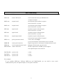
MPC-684 family
Outline of MPC-684 series
MPC-684
main CPU board
serial communication port (RS-232) 3ch
4 outputs 8 inputs
MOP-096
output board
96 transistor open-collector outputs
max 4 boards in a system.
MOP-048
output board
48 transistor open-collector outputs
max 8 boards in a system.
MIP-096
input board
96 photo-coupler isolated inputs
max 4 boards in a system.
MIP-048
input board
48 photo-coupler isolated inputs
max 8 boards in a system.
IOP-048
input/output board
24 photo-coupler isolated inputs,
24 transistor open-collector outputs.
MPG-314
pulse generation board
4-axis. max seed 4Mpps
s-curve acceleration / deceleration, max 10 boards
MBK-SH
touch panel interface
Digital corporation’s touch panel communication board.
MRS-402
serial communication board
RS-232 or RS-485 2ch. max 2 boards.
MPC-SLNK
remote I/O board
SUNX corporation’s S-LINK system support.
512 inputs/outputs. max 2 board.
RACK-68K3
system rack
3 slots
RACK-N6
system rack
6 slots
RACK-N13
system rack
13 slots
For example
If you combine MPC-684, IOP-048, MPG-314 and RAC-K-68K3 you can build 2 user serial
communication ports, 48 inputs/outputs, 4 axes pulse controller.
5
The feature of the MPC-684
Program capacity
500Kbytes( about 25000 lines)
Point data
4 by 13000 points
Global variable
2000
Local variable
26 ( each task )
Task
from 0 to 31
RS-232 buffer
256 bytes each ports
Real time clock
not supported but you can use the touch panel clock
I/O
8 inputs 4 outputs
Loading power supply
DC5V 2A (with assisted cooling modifications 3A)
Others
string variable, co-processor (option)
2-4M flash ROMs
2-4M static RAMs
co-processor
MC68882FN25 (option)
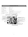
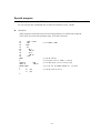
MPC-684F CEP-104B
ACCEL CORP
back up battery
RS-232 CH0
user or touch panel I/F
RS-232 CH1 programing
RS-232 CH2 user
CPU MC68340
I/O
DC24V power
DC5V power supply
6
Program development environment
Hardware
Personal computer
OS: Microsoft Windows supported
Programming cable
Connect to a MPC-684 and a personal computer by RS-232.
If the personal computer doesn’t have a RS-232 port, you should use a
USB-RS converter
Software
You can install software for MPC programming by “Setup Disk”.
You can down-load it from the ACCEL web site.
Main software
FTMW32E.EXE terminal software
FTMWE is the software which connects a MPC-684 and a personal computer
This is used for debugging your program it also reads/writes the program and point data for the PC.
This is indispensable to development.
SYSLDWE.EXE system loader
SYSLDWE is used for the MPC system version upgrade which rewrites flash-rom data to the MPC.
MPCEDE.EXE
off line editor
MPCEDE is an off-line editor only for the MPC.
It classifies control sentences, labels and comments by color.
7
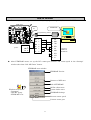
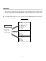
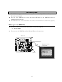
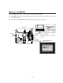
How to connect
Connect a personal computer to the MPC by the programming cable, then turn the MPC on.
MPC-684
FTMW32E
MPC-684F CEP-104B
ACCEL CORP
J1
Programming Cable
power
DC24V 1
2
GND 3
FG 4
SG
1
1 CD
TX0
2
2 RXD
RX0
3
3 TXD
SG
4
4 DTR
MAN
5
5 SG
P5
6
6 DSR
Windows PC
Computer
COM Port
(D-SUB 9)
7 RTS
8 CTS
9 CI
After FTMW32E starts, set up the PC’s comm port number and comm speed in the “Settings”
window after that click “MPC-684” button.
FTMW32E start window
FTMW32E Version
Connect to MPC-684
End of FTMW32E
Off line editor start
Windows start menu
“Programs”
“ACCEL” group
“FTMW32E” icon
System loader start
FTMW32E Settings
Current comm. speed
Current comm. port
8
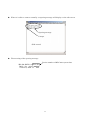
When it is able to connect normally, an opening message will display on the edit screen.
Opening message
Prompt
(Edit screen)
The meaning of the opening message
Version number of MPC-684 system data
MPC-684 ADVFSC(r)eREV-3.82r
BASIC like + multi tasking
Created by ACCEL Co.' 2001
9
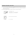
Input commands
There are 3 types of input control.
Direct executed commands: Single command statements executed immediately.
Program executed commands: A series of commands executed from a program after initiating the
run command.
Bilateral commands: Both directly executed commands and program executed commands. Most
commands are bilateral.
can use both
ON 0
OFF 0
PRINT A
MOVE
etc
#ON 0<Enter>
#GOTO 100<Enter>
#10 MPCINIT<Enter>
direct executed
LIST
MPCINIT
ERASE
RUN
etc
program executed
GOTO
GOSUB
IF ~
FOR ~ NEXT
etc
/* direct execution
10 ON 0<Enter> is program (attached number)
/* not happen anything
/* don't write
MPCINIT command in the program.
10
I/O check
There are 2 ways to check input and output conditions.
To check by command
The following are commands used to complete a basic I/O check.
#ON 0
#OFF 0
#PR SW(0)
1
#PG &H400
#PRX HPT(0)
0005
/*
/*
/*
/*
turn the OUTPUT 0 on
turn the OUTPUT 0 off
The state of an INPUT 0 ("PR" is short for "PRINT")
0=off,1=on
/* check of MPG-314 origin sensor port (connecter J4)
/* SX1(J4 No.11 pin) and SY1(J4 No.13 pin) are on
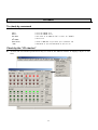
Check by the “I/O checker”
To start the I/O checker push the F8 key or click on the ‘Editor’ button. It displays 3bytes at one
time.
11
You can check about MPG-314's INPUT by "INCHK_314" command.
#INCHK_314
X_S1 ON
Z_S1 __
X_S2 __
Z_S2 __
XIN2 __
ZIN2 __
XIN3 __
ZIN3 __
X-INP __
Z-INP __
X-ALM __
Z-ALM __
XLMT+ __
YLMT+ __
ZLMT+ __
ULMT+ __
#
/* scan start
Y_S1
U_S1
Y_S2
U_S2
YIN2
UIN2
YIN3
UIN3
Y-INP
U-INP
Y-ALM
U-ALM
XLMTYLMTZLMTULMT-
ON
__
__
__
__
__
__
__
__
__
__
__
__
__
__
__
/* scan stop by any key
12
How to input program
To write a program include a line number before the command.
Press the enter key after writing each command, so it can be transmitted to the MPC.
If error messages come out, please check whether there is any mistake in grammar and input again.
10 'this is sample program<Enter>
20 DO<Enter>
30 FOR I=0 TO 48<Enter>
40 ON I : TIME 100<Enter>
50 NEXT I<Enter>
60 LOOP<Enter>
70 pri I<Enter>
.....This command is not supported. m(__)m
70 PRINT I<Enter>
/*
/*
/*
/*
comment
control statement
repeat
multi statement
if error then correct and input again
Multi statement
The MPC can differentiate between statements if they are separated by a colon (:)
1000
WAIT SW(0)==0 : ON 0 : TIME 100 : OFF 0 : TIME 500
Comment
You can write comments after the statements using single quotation marks.
If you write comments after the commands, the statement is automatically changed into a
multi-statement.
#40 ON 0 'COMMENT<Enter>
LIST 40 1<Enter>
40
ON 0 :
'COMMENT
multi-statement
<Caution> If you write a colon in a comment statement the MPC will execute it like other
commands.
10
'COMMENT
: ON 0
/*
ON 0
will execute
Label
The statement which has an asterisk (*) attached to the head is a label. Don’t use a space in it.
10
20
*MAIN
IF SW(0)==0 THEN : GOTO *MAIN : END_IF
/* label
13
Subroutine
A subroutine is a piece of code, much like any code in a program. A subroutine has an entry point
and an exit point. At the entry of a subroutine, the system remembers where to resume execution
when the subroutine finishes. When the subroutine finishes, the system resumes execution at this
location.
If you make subroutines for each job, you can access them from the main routine, it will be easier to
read and customize a program.
Subroutine
Main routine
100 GOSUB *HOME
110 GOSUB *CLAMP
120 GOSUB *UNCLAMP
2000
2010
2020
2030
2040
2050
2060
2070
*HOME
'move to origin
HOME X_A -1000 IN1_ON
WAIT RR(X_A)==0
STPS 0 0 0 0
PRSET_ACCEL X_A
FEED X_A 0
RETURN
3000
3010
3020
3030
3040
*CLAMP
'seize
ON 0
OFF 1
RETURN
4000
4010
4020
4030
4040
*UNCLAMP
'release
ON 1
OFF 0
RETURN
14
Parameter of subroutine, return value
You can set a subroutine with parameters. The parameter values are activated by the main routine
using the 'VAR' command. The command 'RETURN' ends the subroutine's program and commences
the main routines next step.
If the value combines with a local variable, some tasks can share the subroutine.
10
20
30
40
50
60
10
20
30
40
50
60
70
GOSUB *SUB 1 2 3
END
*SUB
_VAR A! B! C!
PRINT A! B! C!
RETURN
GOSUB *SUB
_RET_VAL A
PRINT A
END
*SUB
C!=123
RETURN C!
/* send parameter values
/* A!,B!,C! (with ! ) are local variables.
/* get parameter values in the subroutine.
/* get return value from the subroutine
/* C! = return value
15
Edit of a program
Explanation of useful operations for editing a program
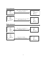
LIST display
‘LIST’ is the command used most.
LIST [n,m]
n: Start line number or LABEL
m: The number of lines to display
You can view the program's first block of code by entering 'LIST' ( figure 16-1), if you enter 'LIST'
once more it will display the next block. And so on consecutively.
You can specify a line number or label to view by inputting it in the first parameter. (figure
16-2,16-3)
You can specify the number of lines displayed in the 2nd parameter. (figure 16-4)
You can view the program from the beginning by entering 'LIST 0'. (figure 16-5)
[16-1]
#LIST
10
20
30
[16-4]
#LIST *MANU 2
100
*MANU
110
'MANUAL JOB
IF SW(192)==0 THEN
GOTO *MANU
ELSE
[16-5]
#LIST 0
10
20
30
40
50
100
110
200
210
[16-2]
#LIST 40
40
GOTO *AUTO
50
END_IF
100
*MANU
[16-3]
#LIST *MANU
100
*MANU
110
'MANUAL JOB
200
*AUTO
16
20
IF SW(192)==0 THEN
GOTO *MANU
ELSE
GOTO *AUTO
END_IF
*MANU
'MANUAL JOB
*AUTO
'AUTO JOB
Insert statement
10
20
30
40
*LOOP
ON 0
OFF 0
GOTO *LOOP
10
20
30
40
25 TIME
*LOOP
ON 0
OFF 0
GOTO *LOOP
50<Enter>
Move cousor to the 30th line
then press 'Ctrl+N'.
Input the new string and line number
that you want to insert.
10
20
25
30
40
*LOOP
ON 0
TIME 50<Enter>
OFF 0
GOTO *LOOP
LIST
10
20
25
30
40
*LOOP
ON 0
TIME 50
OFF 0
GOTO *LOOP
LIST
10
20
30
40
*LOOP
ON 0
OFF 0
GOTO *LOOP
LIST
10
20
30
40
*LOOP
ON 0
OFF 0
GOTO *LOOP
Delete statement
LIST
10
20
25
30
40
*LOOP
ON 0
TIME 50
OFF 0
GOTO *LOOP
LIST 0
10
*LOOP
20
ON 0
25
TIME 50
30
OFF 0
40
GOTO *LOOP
25<Enter>
Move cursor to the 25th line
then press 'Ctrl+Y'.
Input the line number.
The statement will be deleted.
17
Other key operations
18
How to program save to the PC, load from the PC
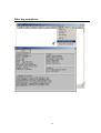
Program save to the PC
You can save the program to your PC by pushing 'F9' then selecting 'Program Save'
from the menu.
The program is saved under the extension 'F68'.
Saved programs don't have line numbers.
19
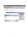
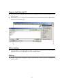
Program load from the PC
You can load the program from your PC by pushing 'F9' then selecting 'Program Load'
from the menu.
Line numbers are in intervals of ten by default. If it exceeds 6000 it will be 'RENUM' to
intervals of 5 automatically.
Off line editing
Unless FTMW is connected with the MPC, it cannot be used, however you can create a
program off-line using ‘MPCED’ or another common editor.
Printing
FTMW cannot print a program. Please print the file saved in the PC by MPCED or
another editor.
20
I/O control
You can control an I/O Port for every bit or byte.
Bit operating is for simple device control. ex. solenoid valves, relays and switches etc.
Byte operating is used for reading DSW, data exchange with external devices etc.
Bit control
ON 0
OFF 1
WAIT SW(192)==1
IF SW(1)==1 THEN : GOTO *LABEL : END_IF
ON -1
WAIT SW(-2)==0
/*
/*
/*
/*
/*
/*
output #0 turn on
output #1 turn off
wait for input #192 to turn on
conditional branch
negative number = memory I/O.
Byte control
OUT 170 0
/*
A=IN(0)
/*
OUT A B
/*
WAIT IN(1)==255
/*
IF IN(2)==&H0F THEN : GOTO *LABEL : END_IF
OUT &HFF -1
/*
WAIT IN(-1)==&HAA
/*
21
170(decimal) is outputted to bank #0.
the value of bank#0 loads to variable A.
the value of A loads to out-port B.
wait to reach 255.
/* conditional branch
negative number is memory I/O.
Variable, Array variable, String variable, Memory I/O
MPC-684 has a lot of variables, array variables, string variables and memory I/Os.
These are in integers of 4 bytes.
Variables and array variables are used for calculation, counting as usual. Memory I/Os
are usually used for interlocking tasks.
Most commands and functions can use constants, variables and array variables in their
parameters.
You can control memory I/Os as usual by using ON, OFF, OUT, SW commands.
You can view their current state by entering ‘VLIST’.
Variable
You can set the parameters of a command using variables or numbers.
Parameters, commands, functions, constants and reservation strings cannot share the
same name.
You don't need to define them in the program as ‘Language C’, but you have to initialize
variables in the program.
10
20
SOL1=0
ON SOL1
/* SOL1 is a variable
/* turn on
You can make constants by ‘CONST’.
10
20
CONST SOL1 0
ON SOL1
You can't change constant's value.
10
20
30
#RUN
#30
CONST SOL1 0
ON SOL1
SOL1=1
/* changes the value.
.....Attempted modification of a constant.
Local variable
The local variables are available for each task. They are assigned to the specific
memory areas of each of the individual tasks. Each of the tasks can share a subroutine.
A!=B!+C!
/*
! indicate local variable.
22
Array variable
A DIM command secures specific array variable partitions in the memory.
10
20
30
40
DIM ARRY(100)
FOR I=0 TO 99
ARRY(I)=I
NEXT I
/* secure ARRY(0) ARRY(99)
You can use two-dimensional arrays.
10
DIM ARRY(2,3)
Point data is also a kind of array variable.
You can save (load) the point data to the PC. The PLS command displays the point data list.
#NEWP
/* point data clear
#X(1)=999
#Y(1)=998
#U(1)=997
#Z(1)=996
#PLS
p1
X= 999 Y= 998 U= 997 Z= 996
--p21
X= 0 Y= 0 U= 0 Z= 0
p22
/* Q key quits display. other key continue
String array variable
There is a string array variable named 'AR$'.
A DIM_AR$ command secures memory for AR$.
10
20
730
#run
ACCEL
DIM_AR$ 35 4000
/* AR$(0) AR$(3999): 4000 variables
AR$(3000)="ACCEL"
PRINT AR$(3000)
Caution: A string array variable shares the point data memory area.
#DIM_AR$
Length=35 Count =4000 P(MAX)=4249
/* just 'DIM_AR$' = confirm using memory
/* 35 characters * 4000 arrays, 4249 available point data
Memory I/O
A negative number denotes memory I/O.
ON ‒ 1
WAIT SW(-1)==1
OUT 255 ‒ 2
/* turn on bit -1
/* wait for bit to turn on
/* 255 loads to bank -2 (bit ‒ 9 -16)
23
Calculation
+
*
/
%
&
|
¥
addition
substruction
multiplication
division
surplus
logical multiplication (AND)
logical addition (OR)
exclusive-OR (XOR)
A=B+C
A=B-C
A=B*C
A=B/C
A=B%C
A=B&C
A=B|C
A=B¥C
The integers are 4 bytes in value. The final value is always truncated to it’s decimal
point.
10
20
30
RUN
2
A=5
B=A/2
PRINT B
The calculation below is in accordance with general arithmetic operation.
10
20
30
RUN
14
A=2 : B=3 :
D=A*(B+C)
PRINT D
C=4
You can carry out floating-point operations and trigonometrical function operations
using a coprocessor (option).
24
Pulse generation
This chapter introduces pulse generating using the MPG-314 board.
It explains how to utilize the MPG-314 for an XY robot.
Initial settings
Initialize the setting on the MPG-314 board before using it.
At first you have to assign the MPG-314 board to any Tasks by using the PG command.
Next, you set the MPG-314 board using ACCEL, FEED etc.
You can do this by direct command, but you have to write the commands in your
program.
For example
PG &H400
ACCEL ALL_A 5000
FEED ALL_A 0
INSET_314 ALL_A ALM_ON¦INP_OFF
STPS 0 0 0 0
/*
/*
/*
/*
MPG-314(address is &H400,it sets by DSW)select.
maximum speed set
drive speed set
In port set. 'ALARM' enabled on signal 'ON', 'INPOSITION'
enabled on signal 'OFF'.
/* setting the present position
How to check operation by TEACHING MODE.
You can easily check about pulse generating by using the TEACHING MODE. FTMW is
set to TEACH MODE with the T key.
current PG address
value of each axes
inching distance
task number
PG[0,400] X= 500 Y= 500 U= 0 Z= 0
dx= 500 dy= 500 du= 500 dz= 500
'Inching' distance can be changed with the 0~3 key. (Their values are set by SET
command.)
[default] key0=10puls / key1=50puls / key2:100puls / key3:500puls
Each axis can be moved by using the X,x,Y,y,U,u,Z,z keys.
If you hit the P key, FTMW requires you to input a point number.
You can change the PG number by using the Tab, +, - keys.
Exit with the Q key from TEACH MODE.
25
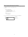
Setup of maximum high speed and acceleration.
Maximum high speed and acceleration can be set by using the ACCEL command. Drive
speed can be decided by using the FEED command.
Format
ACCEL [n] [s] max [long min]
n: axis constant X_A Z_A
s: S-curve acceleration parameter ‒ 1 -100
max: maximum high speed 1 4Mpps
long: acceleration / deceleration pulse count
min: start up pulse rate
FEED n m
n: axis constant X_A Z_A
m: drive speed 0 255
The relationship between ‘ACCEL [n] [s] max [long min]’ and ‘FEED n m’
max
FEED n 0
min
FEED n 255
long
26
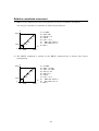
Move to the origin (HOME)
HOME is the command for programming the movement of a robot back to the staring
point of its action.
Format
HOME n rate cond [n1 rate1 cond]
n: axis constant X_A Z_A
rate: pulse rate (pps)
cond: input condition INx_ON INx_OFF
Y
CW
CCW
CW
X
CCW
YS1 (Y origin)
XS1 (X origin)
XS1=the 11th pin of J4 connector on the MPG-314 board.
YS1=the 13th pin of J4 connector on the MPG-314 board.
10
PG &H400
20
ACCEL ALL_A 5000
30
FEED ALL_A 0
40
GOSUB *HOME
50
END
60 *HOME
70
RMVL 500 500 0 0
/* move in an opposite direction from origin (CW)
80
WAIT RR(ALL_A)==0
/* wait until moving complete
90
HOME X_A -500 IN0_ON Y_A -500 IN0_ON
/* CCW movement until the sensor turns on
100 WAIT RR(ALL_A)==0
/* wait until movement complete
110 STPS 0 0 0 0
/* setting current position to ZERO
120 PRSET_ACCEL ALL_A
/* ACCEL parameters restore
130 FEED ALL_A 0
/* FEED reset
140 RETURN
27
Absolute coordinate movement
1) MOVL is the command for linear interpolation.
You can give variables or constants to define the parameters.
5000
Y
10
20
30
40
50
60
PG &H400
ACCEL 5000
/* acceleration/deceleration setting
FEED ALL_A 128 /* speed setting
CLRPOS
MOVL 5000 5000 VOID VOID
WAIT RR(ALL_A)==0
X
0
0
5000
2) Also, you can give a teaching point to the MOVE command parameter.
The teaching points are set by using the 'teaching mode' or by programming.
Y
P(2)
P(1)
0
10
20
30
40
50
60
70
80
X
PG &H400
ACCEL 5000
FEED ALL_A 128
CLRPOS
MOVL P(1)
WAIT RR(ALL_A)==0
MOVL P(2)
WAIT RR(ALL_A)==0
0
3) The MOVS command is similar to the MOVL command but it doesn't have linear
interpolation.
You can set different acceleration (speed) on each axis.
5000
0
Y
X
0
10
20
30
40
50
60
70
80
PG &H400
ACCEL X_A 5000 /*
ACCEL Y_A 10000 /*
FEED X_A 128
/*
FEED Y_A 0
/*
CLRPOS
MOVS 5000 5000 VOID
WAIT RR(ALL_A)==0
5000
28
X-axis
Y-axis
X-axis
Y-axis
VOID
acceleration/deceleration setting
acceleration/deceleration setting
speed setting
speed setting
Relative coordinate movement
1) RMVL is the command for linear interpolation of relative coordinate movement.
You can give variables or constants to define the parameters.
5000
Y
I=5
I=4
I=3
1000
0
I=2
I=1
0
1000
X
10
20
30
40
50
60
70
80
PG &H400
ACCEL 5000
FEED ALL_A 0
CLRPOS
FOR I=1 TO 5
RMVL 1000 1000 0 0
WAIT RR(ALL_A)==0
NEXT I
5000
2) The RMVS command is similar to the RMVL command but it doesn't have linear
interpolation.
5000
Y
I=5
I=4
I=3
I=2
1000
0
I=1
0
1000
X
5000
10
20
30
40
50
60
70
80
90
10
PG &H400
ACCEL X_A 5000
ACCEL Y_A 10000
FEED X_A 128
FEED Y_A 0
CLRPOS
FOR I=1 TO 5
RMVS 1000 1000 0 0
WAIT RR(ALL_A)==0
NEXT I
29
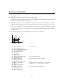
Continuous interpolation
The following figure is an example of continuous interpolation by using the MOVT
command.
It sets point data between the 10 line and the 50 line.
In this case, P(100) is the base point of the coordinates. P(101)~P(104) are local points
(relative coordinates to the base point).
The MPC interpreter reads a MOVT command then executes it. The MPC interpreter
reads the next program step while the previous step is being executed. If you use the
I/O port to control an action in the middle of any program step (that is being executed)
you have to consider the time gap between the working position and the next program
execution step.
The following program is output #0 turn on from P(101) to P(102).
Y
P(103)
P(104)
2000
P(102)
1000
0
P(100) P(101)
X
0
1000
10
20
30
40
50
60
70
80
90
100
110
120
130
140
150
160
170
180
190
200
SETP 100 0 0 0 0
SETP 101 2000 0 0 0
SETP 102 2000 1000 2000 500
SETP 103 1000 1000 0 0
SETP 104 0 1000 0 0
PG &H400
ACCEL 5000
STPS 0 0 0 0
MOVL 1000 1000 VOID VOID
WAIT RR(ALL_A)==0
HOUT X_A;DS_DACL
MOVT X_A¦Y_A P(101)
MOVT X_A¦Y_A P(102) CCW
MOVT X_A¦Y_A P(103)
ON 0
MOVT X_A¦Y_A P(104)
OFF 0
HOUT X_A;EN_DACL
WAIT RR(ALL_A)==0
MOVL 0 0 VOID VOID
3000
/* the base point
/* move to the base point
/* acceleration/deceleration disable
/* dummy point for output #0 turn off at P(102)
/* output #0 turn on from P(101) to P(102)
/* acceleration/deceleration enable
30
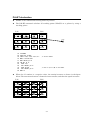
PALET declaration
PALET is the command for moving between palettes.
The PALET command calculate all working points (PLn(N)) on a palette by using 3
teaching points.
P(11)
PL1(1)
P(12)
PL1(2)
PL1(3)
PL1(4)
P(1)
PL1(5)
PL1(6)
PL1(7)
PL1(8)
PL1(9)
PL1(10)
PL1(11)
PL1(12)
P(13)
10
20
30
35
37
40
50
60
70
80
90
PG &H400
ACCEL ALL_A 5000
PALET1 P(11) P(12) P(13) 4 3
MOVL 0 0 VOID VOID
WAIT RR(ALL_A)==0
FOR N=1 TO 12
MOVL P(1)
WAIT RR(ALL_A)==0
MOVL PL1(N)
WAIT RR(ALL_A)==0
NEXT N
/* declare PALET
/* move to point (N) on the PALET
When the 'N' number is a negative value, the motion becomes as shown in the figure
below. The movement between columns becomes smaller, and thus the speed increases.
P(11)
P(12)
PL1(-1)
PL1(-2)
PL1(-3)
PL1(-4)
PL1(-8)
PL1(-7)
PL1(-6)
PL1(-5)
PL1(-9)
PL1(-10)
PL1(-11)
PL1(-12)
P(13)
31
Conditional stop
Pulse generation stops after sensors receive data indicating the need for the stop condition
to take effect.
1) The STOP command executes after the MOVL command. You can use normal input
ports (on the MIP, IOP board) for the stop parameters.
10
20
30
40
50
60
70
PG &H400
ACCEL 1000
FEED ALL_A 0
MOVL 5000 5000 VOID VOID
WAIT SW(192)==1
STOP ALL_A STP_I
WAIT RR(ALL_A)==0
/* STP_I : without deceleration, STP_D : with deceleration
2) You can set the stop conditions before executing the MOVL command. In this case
you have to define specific input ports (IN3, LMT, ALM) on the MPG-314 board for the
stop parameters.
10
20
30
40
50
60
70
80
PG &H400
ACCEL 1000
FEED ALL_A 0
STOP ALL_A IN3_ON
/* set stop condition. if X-IN3(J2 connecter pin1) turn on then stop.
MOVL 5000 5000 VOID VOID
WAIT RR(ALL_A)==0
IF RR(IN3_)<>0 THEN : PRINT "IN3stop" : END_IF
/* confirming reason for stop
STOP ALL_A VOID
/* reset stop condition
32
Multi-task
MPC-684 has 32 tasks ( task0 : Main-task. task1~31 : sub-tasks)
Main-task executes immediately after the RUN command (program mode) or MPC-684
power-on (auto mode). Sub-tasks are executed from main-task.
There isn't any prioritization of sub task. A sub task can execute or cancel out other sub
tasks.
The commands for multi-task
FORK,END,QUIT
The FORK command executes a sub-task.
The task is cancelled by the END command included in that task or by using the QUIT
command in a different task.
PAUSE,CONT
The PAUSE command pauses other tasks execution.
The CONT command enables the task to continue after it has been paused by the PUASE
command stop.
10 FORK 1 *TASK1
20 WAIT SW(192)==1
30 QUIT 1
40 OFF 0
50 END
60 *TASK1
70 DO
80
ON 0 : TIME 500
90
OFF 0 : TIME 500
100 LOOP
/* sub-task1 execute
/* sub-task1 destroy
33
RS-232 communication
MPC-684 has two RS-232 communication ports for interfacing to external devices.
You can control the ports by using commands.
One of the ports supports interfacing with the GP touch-panel (Digital corporation).
You can add more communication ports by using the MRS-402 board (max 4ch.)
Command for communication
CNFG#n
channel n initialize
PRINT#n
channel n transmit
INPUT#n
channel n receive
CNFG#0 "9600b8pns1XON"
INPUT#0 a$
b$="&H"+a$
v=VAL(b$)
PRINT "&H"+a$ "=" v
PRINT#0 HEX$(v)+"\n"
/*
/*
/*
/*
/*
/*
9600bps 8bit parity-none 1stop XON/OFF
string receive
string processing
conversion string to variable
display to monitor screen ( the FTMW )
transmit
34
Debugging
Basic debugging (run/stop/check)
One useful basic process of debugging of the MPC is by executing the program, stopping
it and then checking previous tasks program steps.
For instance, if a machine that is in operation stops, you can look for the cause of
stoppage.
FTMW displays the stop lines of each task by using 'Ctrl+M'.
10
20
30
#RUN
ON 0
WAIT SW(192)==1
OFF 0
/* RUN -> if the machine stopped -> program stop by using 'Ctrl+A'
*0
#
TASK0 20
[20]
WAIT SW(192)==1
/* Display stop line(s) by using 'Ctrl+M'
/* Why did program stop here?
Use the PRINT command
You can monitor the variables, I/O, etc. by using the PRINT command in the program.
10
20
30
40
50
#RUN
count=1
count=2
count=3
C=0
DO
C=C+1
PRINT "count=" C
LOOP WHILE C<3
/* monitoring variable C
Subroutine execute
You can execute any subroutine by using the RUN command.
10
DO
20
GOSUB *FLICK
30
LOOP
40
*FLICK
50
ON 0
60
TIME 50
70
OFF 0
80
TIME 50
90
RETURN
#RUN *FLICK
#90
.....Return not called from a subroutine
35
/* execute the subroutine *FLICK
/* end of the subroutine
How to know the cause of machine stoppage
When the machine stops while in automatic operation, please connect the MPC-684 to
FTMW without turning off the power supply of the machine.
<< The machine stopped! Why? Connect to FTMW soon! >>
VER
MPC-684 ADVFSC(r)eREV-3.82v
BASIC like + multi tasking
Created by ACCEL Co.' 2001
/* MPC-684 connecting to FTMW
#MON
/* You can know condition by using the MON command
*0 [20]
#
/* FTMW displays condition by using 'Ctrl+M'
TASK0 20
WAIT SW(192)==1
/* task0 stopped at 20, waiting switch 192 turns on
#LIST 0
10
ON 0
20
WAIT SW(192)==1
30
OFF 0
How to read the programming port output log.
The FTMW displays RS-232(ch1:program port) log data when you use the LOG
command. You can find runtime-errors by using it.
The MPC-684 has 1k byte memory for logging that ring-buffer.
You can buffer clear input 'LOG 0'.
The MPC-684 can't log runtime-errors that happened during a task0.
LIST
10
20
30
#LOG 0
#RUN
1
2
#LOG
1
2
FOR I=1 TO 2
PRINT I
NEXT I
/* clear log data
/* PRINT output under executing
/* watch log data
/* log data in the memory
#
36
Special program
The prompt returns to the FTMW when task 0 is ended using the END command. Then
you can execute the commands for an I/O and variable's value, checks.
<Caution>
*The program currently being executed stops when you modify the program.
*You can't use Ctrl+A for program stop. Use Ctrl+] instead.
10
FORK 1 *JOB1
20
END
30
*JOB1
35
DO
40
ON 0
50
TIME 50
60
OFF 0
70
TIME 50
80
LOOP
#RUN
#
TASK0 20
END
TASK1 70
TIME 50
#PRINT SW(0)
1
#
*0 [20]
*1 [50]
#
/* the TASK0 is END
/* program execute
/* The prompt returns. TASK1 is running
/* Crtl+M display current running steps
/* You can use the PRINT command for I/O check
/* program stops by Ctrl+]
37
Use touch panel
The MPC-684 supports the 'Direct access protocol' on the Digital Electron Corporation’s
GP series touch panel.
You can select MBK-RS (by using J2 on the MPC-684) or the MBK-SH board for
communication to the GP.
The MPC-684 has a 1000 words data area and a 100 words I/O area of memory capacity.
When you use MBK-RS
You have to write 'PROTOCOL MEWNET' at top of the program.
10 PROTOCOL MEWNET
You can't use the MBK-RS and the RS-232 CH0 at the same time.
ACCEL CORP
MPC-684F CEP-104B
MPC-684
J2 (RS-232 9600bps)
Digital GP series
touch panel
DC24V
38
When you use MBK-SH
The MBK-SH connects to the touch panel at RS-422 38400bps.
The MBK-SH board is an independent CPU board, therefore doesn't put strain on the
main CPU board.
You can use the MBK-SH for communication with another controller.
MBK-SH
RS-232/422 9600/19200/38400bps
Personal computer
Omron, Mitsubishi, Matsushita
controller
MBK-SH CEP-098A
MPC-684
ACCEL CORP.
DC24V
39
RS-232/422 38400bps
Digital GP series
Command List
I/O
?
ALT
CLR_OUTP
HIN
HIN
HOUT
HPT
HSW
IN
IO
IOR
IOW
OFF
ON
OUT
P_HSW
P_IN
P_IN
P_OFF
P_ON
P_OUT
P_SW
SENSE_SW
SETIO
SW
WS0
WS1
Reading of Bit (HSW Alternative)
Switch ON/OFF
Initialize Output (specified the board)
Parallel Input
Parallel Input (Read 4 bytes)
Pulse Board General Output
Pulse Board General Input
Read Bit
Parallel Input
I/O Monitor
Read BUS
Write BUS
Output off
Output on
Parallel Output
Output/Input of MPC-684 J4 Connector
Output/Input of MPC-684 J4 Connector
High Speed Input MPC-684 J4Connector
Output/Input of MPC-684 J4Connector
Output/Input of MPC-684 J4Connector
Output/Input of MPC-684 J4Connector
Output/Input of MPC-684 J4Connector
Output Operation on Input Detection
Initialize Output
Bit Input
Input with Time Out
Input with Time Out
MBK-SH/RS
ADD_MBK
CHR$
DIMCPY
LD_M
MBK
MBK
S_MBK
S_MBK
SV_M
Data Increment
Conversion from ASCII to String
Copy Arrays
Memory Bulk Copy (MPC to MBK)
Reading of Data Area
Verification of Backup Status
Write Data Area
String Forward
Memory Bulk Copy (MBK to MPC)
MPG-314 Exclusive
ACCEL
ERR_PAUSE
FEED
FEED
HOME
HOUT
HOUT
Creation of Acceleration/Deceleration Table
Control of Task on Error
Speed setting
Speed setting(Minute Setting)
Stated Low Speed Return to the origin
Port Output
Control Register
40
HPT
INCHK_314
INSET_314
M_RMVS
MOVL
MOVS
MOVT
PG
PLSC
PRSET_ACCEL
RANGE
RMVC
RMVL
RMVS
RMVT
RR
STOP
STPS
STPS
U
WARP
X
Y
Z
Read Input Port
Input Monitor
Set Input Port Function
Asymmetric Acceleration/Deceleration Move
Linear Interpolation (Absolute Coordinate Move)
Axis Independent Pulse Generation (Absolute Coordinate Move)
Continuous Interpolation (Absolute Coordinate Move)
PG Declaration
Pulse Generation at a Constant Speed
Reset ACCEL Parameter
Operative Restriction
Infinite Pulse Generation
Linear Interpolation (Relative Coordinate Move)
Axis Independent Pulse Generation (Relative Coordinate Move)
Continuous Interpolation (Relative Coordinate Move)
Read Register
Conditional Stop
Specify Current Position
Set Counter
Read Counter
Warp Jump
Counter Reading
Read Counter
Read Counter
MPG-3202 Exclusive
CMND
REG
REG3
ST_REG
X3202 Command Execution
Read X3202 Register
Read X3202 Register
X3202 Register Writing
MPG-68K Compatible
ACCEL
BSY
CLRPOS
CURPOS
FEDD
FEDH
FEDT
FEDZ
FEED
GO
HOME
HOMZ
JMPZ
JUMP
LIMZ
MOVE
MOVZ
P
PALET1
PALET2
PALET3
Creation of Acceleration/Deceleration Table
PULSE Generation Status Input
Clear current position
Display current position
Speed setting
Speed setting
Speed setting
Speed setting
Speed setting
4 axes simultaneous PULSE GENERATION
Return to the origin
Return to the origin
Gate motion move
Gate motion move
Limit of Gate Motion
XYU Absolute Coordinate Move
Z Absolute Coordinate Move
Point Data
PALET Declaration
PALET Declaration
PALET Declaration
41
PALET4
PG
PGSEL
PL1
PL2
PL3
PL4
PULSE
Q_PAUSE
RANGE
RM
RMOV
RMVZ
SET
SETP
SETPOS
SHMZ
SHOM
STOP
TEACH
U
X
Y
Z
PALET Declaration
PG Declaration
PG Declaration
Palette Point
Palette Point
Palette Point
Palette Point
Pulse Generation at a Constant Speed
Quick Pause
Operative Restriction
4-axis Relative Coordinate Move
XYU-axis Relative Coordinate Move
Z-axis Relative Coordinate Move
Setting Inching Amount
Sets point data
Change Current Value
Setting Return to the Origin
Setting Return to the Origin
Stop Pulse Generation
Teaching Mode
U-axis Point Data
X-axis Point Data
Y-axis Point Data
Z-axis Point Data
RS-232
CNFG#0
CNFG#2
INP$#0
INP$#2
INPBLK#
INPUT
INPUT#0
INPUT#2
INPUT$
LOF
PRINT
PRINT#0
PRINT#2
PROTOCOL
PRX
PUT
PUT#0
PUT#2
RS
RSE
RSE
SLOW
Setting of Communication Mode
Setting of Communication Mode
Read n Character
Read n Character
Binary Fixed Format Input
Data Input
Data Input
Data Input
Read n Character
Number of Character of Buffer
Data Output
Data Output
Data Output
MBK-RS (Digital GP Direct Access)
Data HEX Display
Data Output
Data Output
Data Output
Display Buffer
RS-232C ERROR
CH1 Character Input
CH1 Character Transmission Interval
Calendar
date$
time$
timer
Get Date String
Get Time String
Get Time
42
Floating Point Operation
CALF
GETF
PRF
SETF
Arithmetics
Retrieve Data
Display Internal Data
Delivery of Data
System
FCLK
MPC
Change Clock Speed
MPC-816 COMPATIBLE
Timer
SYSCLK
TIME
TMOUT
System Clock
Wait Time
Set Input Time
Task Operation
CONT
FORK
LIFE_TIME
PAUSE
QUIT
RLS
RSV
SWAP
TASKN
Continue Task
Task Execution
Set the Life Time of Task
Pause Task
Stop task
Release Semaphore
Semaphore capture
Abandonment of Execution
Task Number Get
Debug
CNT
DUMP
FIND
FIX
LOG
MON
RAM
ROM
RUN
TASK
TOFF
TON
Continue Execution
Display of Memory
Search String
Write to Flash ROM
Program Port Output Record
Verification of Stop Status
Receipt of Return Value
Flash Rom Mode
Execute Program
Task Status Display
Trace mode
Trace mode
Bus Access
WIR
WOW
Word Reading
Word Writing
File Memory
P_LD
P_SV
Read Point Data from Flash ROM
Write Point Data in Flash ROM
43
Memory Access
PEEK
POKE
Readout of User Memory
Write User Memory
Maintenance
ERASE
MEM
MPCINIT
TMON
VER
Clear Program of Flash ROM
Memory Test
Initialize RAM Area
Task Monitor
Version Data Display
User Command
ADR
COMSET
Obtain the address
Setting of Command Name
Arithmetic
@
ABS
AND
ATAN
ATAN2
CONST
COS
DIM
DIM
LET
NOT
OR
SFTL
SFTR
SIN
SQ
SQR
SWP
TAN
Logical Negation
Absolute value
Logical Sum Expression (Logical Multiplication)
Trigonometric Function
Trigonometric Function
Conversion from variable to constant
Trigonometric Functions
Arrays Declaration
Arrays Declaration (two dimensional)
Expression Execution
Complement
Logical Merge (Logical Sum)
Array Variables Rotate
Array Variables Rotate
Trigonometric Functions
Square
Square Root
Switch Upper/Lower Bytes
Trigonometric Functions
Control Statement
BREAK
BREAK
CASE
CASE_ELSE
DO
ELSE
END
END_IF
END_SELECT
FAST
FOR
GOSUB
End of Control Flow (BREAK from
End of Control Flow (BREAK from
Conditional Branch Dependent On
Conditional Branch Dependent On
Loop
Conditional Branch
End of Program
Conditional Branch
Conditional Branch Dependent On
Stop SWAP Function
Loop
Subroutine Call
IF Statement)
LOOP)
Value
Value
Value
44
GOSUB
GOTO
IF
LOOP
NEXT
_RET_VAL
RETURN
RETURN
SELECT_CASE
THEN
UNTIL
_VAR
WAIT
WEND
WHILE
Subroutine Call (Argument Pass)
Unconditional Branch
Conditional Branch
Loop
Loop
Receipt of Return Value
Return
Return Value Passing
Conditional Branch Dependent On Value
Conditional Branch
Conditional Statement
Receipt from Arguments
Wait for a condition
Condition Loop
Condition Loop
String
AR$
ASC
CHR$
DIM_AR$
DIMCPY
GET_VAL
HEX$
LEN
STR$
STRCPY
VAL
VER$
String Arrays
Conversion from String to ASCII
Conversion from ASCII to String
String Arrays Declaration
Copy Arrays
Automatic Numeric Numbers Retrieve from String
Conversion form String to Hex
Get Number of Character
Convert from Numeric Value to String
Copy String
Numbers from Numeric String
Version Data Get
Edit
DELETE
FREE
LIST
NEW
NEWP
PLIST
RENUM
TAIL
VLIST
Delete of Program
Display Available Memory
Display Program
Initialize Program
Initialization of point data
Display Point Data
Reset Sentence Number
Maximum of Statement Number
Program Reference Display
--- End Of Document ---
45


![[an2k-035] MPG-2314精度の高い同期動作](http://vs1.manualzilla.com/store/data/006544011_2-41f2cdf14e8aaa0d732a1963107d08bb-150x150.png)