1
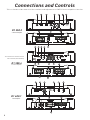
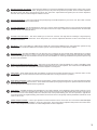
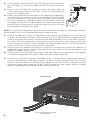
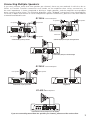
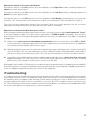
AMPLIFIER INSTALLATION MANUAL
D1 250.2 | D1 300.4 | D1 400.1
Congratulations!
Thank you for choosing a Diamond Audio Technologies D1 Series amplifier. We sincerely believe that DAT products offer you outstanding performance and value. DAT products are engineered and produced with the highest quality materials and incorporate the latest technology. We
think you will find your new DAT amplifier meets or exceeds your expectations and provides excellent value.
Properly installed, your new DAT D1 Series amplifier will provide years of high quality sonic reproduction. Before installing the DAT amplifier in
your vehicle, please read the entire manual carefully. It is required reading for the protection of your vehicle and for the maximum performance of
your mobile audio system. All DAT amplifiers have been extensively tested and “burned-in” for maximum reliability. If after reading this manual,
you still have questions regarding this product, we recommend that you contact your authorized DAT dealer for expert installation assistance.
If you need assistance with repair or warranty, detailed warranty and return/repair information is listed in the back of this manual. Be sure you
record your serial number, model number and date of purchase for your DAT amplifier as this will be necessary for any returns.
Please Practice Safe Sound!
Continuous exposure to sound pressure levels over 100 dB may cause permanent hearing loss. High powered mobile audio systems may produce
sound pressure levels well over 130dB. Use common sense and practice safe sound.
All Diamond Audio D1 Series Amplifiers Feature:
• Pulse Width Modulated (PWM) MOSFET Switching Power Supply
•Extruded Aluminum Heatsink
•Nickel Plated RCA Low Level Audio Inputs
•Nickel plated, low resistance power and speaker connector blocks
• Power ON and Protection LED Lighting for Easy Diagnostics
• Thermal, Short Circuit, and Overload (Low Impedance) Protection
• 6dB bass boost
• Chassis mounted ATC/ATO type automotive fuses
• Proudly Designed and Engineered in the USA
D1 250.2 / D1 300.4 Features
•Class AB Amplifier Topology
• Bridgeable Output Capability (4 Ohms)
• Stereo/Mono Mix Capability (Hybrid 3rd channel from 2 channels)
•Stable into 2 Ohm Stereo Loads
• Internal 12dB/Octave High Pass or Low Pass Filter (40-400Hz)
•Pass -Thru Line Output for Daisy Chaining Amplifiers
• Versatile for either full range or subwoofers
D1 400.1 Features
•Class AB Amplifier Topology
• Internal 12dB/Octave Low Pass Filter (40-250Hz)
• Bass Boost EQ (0 to +6dB) at 50Hz
• Remote Level Control for Dash Mounting
• Intended for use on subwoofers
Frequency Response:
20Hz to 20KHz +/-3 dB
Signal to Noise Ratio:
>95dBA (20 to 20kHz)
Channel Separation
50dB
THD+N(Total Harmonic Distortion + Noise)
<0.2% (Output-1W 4 Ohms)
RCA Input Sensitivity:
150mV to 4V
RCA Input Impedance:
>20K Ohms
Hi-Level Input Sensitivity:
1.5V to 14V
Hi-Level Input Impedance:
32 Ohms
Min to Max Voltage requirements 10.2V to 15.5V DC
High/Low Pass Crossover:
12dB/Oct, 40-400 Variable
Crossover Configuration:
Switchable (OFF/HP/LP)
Bass EQ
0 or 6dB @ 50Hz (Selectable)
Frequency Response:
20Hz to 20KHz +/-3 dB
Signal to Noise Ratio:
>90dBA (20 to 20kHz)
Channel Separation
50dB
THD+N(Total Harmonic Distortion + Noise)
<0.2% (Output-1W 4 Ohms)
RCA Input Sensitivity:
150mV to 4V
RCA Input Impedance:
>20K Ohms
Hi-Level Input Sensitivity:
1.5V to 14V
Hi-Level Input Impedance:
32 Ohms
Min to Max Voltage requirements 10.2V to 15.5V DC
High/Low Pass Crossover:
12dB/Oct, 40-400 Variable
Crossover Configuration:
Switchable (OFF/HP/LP)
Bass EQ
0 or 6dB @ 50Hz (Selectable)
Frequency Response:
20Hz to 20KHz +/-3 dB
Signal to Noise Ratio:
Channel Separation
D1 250.2
2-Channel Amplifier
250 Watts RMS Output Power
(All Channels Driven):
(Into 4 Ohms)
(Into 2 Ohms)
(Bridged into 4 Ohms)
75w x 2
125w x 2
250w x 1
D1 300.4
4-Channel Amplifier
300 Watts RMS Output Power
(All Channels Driven):
(Into 4 Ohms)
(Into 2 Ohms)
(Bridged into 4 Ohms)
50w x 4
75w x 4
150w x 2
>90dBA (20 to 20kHz)
50dB
THD+N(Total Harmonic Distortion + Noise)
<0.2% (Output-1W 4 Ohms)
RCA Input Sensitivity:
150mV to 4V
RCA Input Impedance:
>20K Ohms
Hi-Level Input Sensitivity:
1.5V to 14V
Hi-Level Input Impedance:
32 Ohms
Min to Max Voltage requirements 10.2V to 15.5V DC
Low Pass Crossover:
12dB/Oct, 40-250Hz Variable
Crossover Configuration:
Low Pass only
Bass EQ
0 to 6dB @ 50Hz
D1 400.1
Mono Amplifier
400 Watts RMS Output Power
(Single Channel Driven):
(Into 4 Ohms)
(Into 2 Ohms)
200w x 1
400w x 1
218
x
57.5mm
218
x
57.5mm
218 x 57.5mm
Connections and Controls
This section describes how all of the terminals and adjustments of DAT D1 Series amplifiers function.
3
Primex
3ptPrimex
3pt
10˚
slant
Primex
slant
.33pt
pt10˚line
.3 pt line
10˚ slant
.3 pt line
5
4
FILTER
X-OVER
X-OVER
40Hz 400Hz
X-OVER
40Hz 400Hz
D1.250.2
D1.250.2
D1 250.2
D1.250.2
BASS BOOST
FILTER
HP LP
FLAT
HP LP
FILTER
FLAT
R
L L INPUT
HIGH
L
R
L
ROUTPUT
INPUT
MIN MAX
R
HIGH INPUT
R
L L
INPUT
0dB +6dB
HIGH INPUT
OUTPUT
R
INPUT
OUTPUT
11
2
2-Channel Amplifier
8
L L
L
GAIN
MIN MAX
BASS0dB
BOOST+6dB
GAIN
MIN MAX
9
6
1
GAIN
BASS BOOST
0dB +6dB
HP LP
FLAT
40Hz 400Hz
1
30A FUSE
30A FUSE
+
30A FUSE
GND
+12V
GND REM
+12V
REM
GND
+12V
–
+
+ +L BRIDGE
– –
+ BRIDGE
+ L –
+
+ BRIDGE –
L
–
R
+
–
–
R
–
R
REM
5
BASS BOOST
4
3
10
2
LF
GAIN
X-OVER
LF
LP
HP
FILTER
FLAT
GAIN
X-OVER
LP
+6dB HP
HIGH INPUTFLAT40Hz 400Hz MIN MAX
LF
FILTER
GAIN
X-OVER
MIN
MAX
L
R
40Hz
400Hz
HIGH INPUT
RF
LP
+6dB HP
L FLAT
R
RF
HIGH INPUT 40Hz 400Hz MIN MAX
LR
FILTER
These Functions are Identical for Each
Pair of Channels (Front and Rear)
BASS BOOST
FRONT
D1.300.4
D1.300.4
D1 300.4
4-Channel
Amplifier
D1.300.4
L
R
RF
FRONT
RR
INPUT
6
8
GAIN
L
BASS BOOST
FILTER
X-OVER
LP
0dB
HP
FILTER+6dB
BASS BOOST
X-OVERFLAT
LP
0dB +6dB
HP
MIN MAX 40Hz 400Hz HIGH INPUT
FLAT
LR
L
FILTER
BASS BOOST
GAIN
MIN MAX X-OVER
L 400Hz HIGH INPUT
R
40Hz
RR
R
LP
0dB +6dB
HP
REAR
INPUT
OUTPUT
L FLAT
R
RR
R
MAX 40Hz 400Hz HIGH INPUT
INPUT
OUTPUT MIN REAR
0dB
FRONT 0dB
L
LR
0dBBOOST+6dB
BASS
L
R
OUTPUT
1
GAIN
R
REAR
1
11
25A FUSE
F
25A FUSE
25A
25A
+12V
F
R
25A
GND
25A
25A FUSE
F
+12V
25A
25A
GND REM
REM
+
+
R
GND
+12V
REM
+
9
7
6
1
–+ BRIDGE –+
2
–
REMOTE
L
R
L
HIGH INPUT
INPUT
REMOTE
INPUT
10
R
MIN MAX
BASS BOOST
X-OVER
BASS BOOST
40Hz 250Hz
GAIN
MIN MAX
R
5
X-OVER
GAIN
MIN MAX
L
HIGH INPUT
R
REMOTE L
3
GAIN
R
L INPUT
HIGH
D1.400.1
D1.400.1
–+ BRIDGE –+
–
–+ BRIDGE –+
–
10
L
D1D1.400.1
400.1
R
0dB +6dB
X-OVER
40Hz 250Hz
BASS0dB
BOOST+6dB
40Hz 250Hz
0dB +6dB
R
11
8
INPUT
Mono Amplifier
15A FUSE
15A FUSE
15A
15A
15A
15A
15A
15A
15A FUSE
+
+12V
-
15A
15A
15A
+12V
9
-
-
SUBWOOFER
+
GND
REM
-
+
SUBWOOFER
GND
REM
+
+
GND
+12V REM
+
-
SUBWOOFER
-
1
RCA Input and Pass-Thru Output - These RCA jacks allow for a normal Left and Right channel signal input. Simply connect to the
source unit using RCA type audio cables, keeping them away from power wiring wherever possible. On the 4 channel amplifiers
(D1 300.4) “Front” and “Rear” input jacks are present. The “Pass-Thru” output allows the signal to pass on to other amplifiers.
The Pass-Thru output is unaffected by the onboard crossover.
2
Input Gain Adjustment - This control matches the preamp stage of the DAT amplifier to your source unit. This is NOT a volume
control. The range is between 150mV and 4V.
3
Crossover Adjustment- Use this adjustment to select the crossover point. Remember that your choice will be directed to High
Pass or Low Pass depending upon the position of the adjacent switch. The range of adjustment is limited between 40-400 Hz (D1
250.2/D1 300.4) or 40-250Hz (D1 400.1)
4
Crossover Selection Switch - This switch allows you to select the crossover. Use High Pass for midrange or high frequency
speakers. Use Low Pass for subwoofers. In the OFF position, the crossover adjustment knob has no effect. The D1 400.1 is only
available as Low Pass.
5
Bass Boost - This control adds 0 to +6dB of boost at 50Hz. Be cautious when adding boost to some subwoofer systems as they
may not be able to handle the additional low frequency boost. In the OFF position, no bass boost is added.
6
High Level Input - This plug (included) is for use when the source unit does not have an RCA output. Although this is a popular
method of connecting a factory car stereo, some systems may require additional adapters. The far left side of the plug is the LEFT
channel; the far right side is for the RIGHT channel. The wire in the middle is for chassis ground ONLY if the system is experiencing
excessive noise problems.
7
Remote Level Adjustment (D1 400.1 Only) - This port is for the remote level control (included). The control is intended to allow
the user to control the level of gain up to the maximum adjustment level set on the amplifier. The control does not add additional
boost, it only attenuates the setting that is fixed at the amplifier’s control panel.
8
Status LED’s - These lights indicate when the amplifier is powered up normally and when there is a protection fault. See the
“Troubleshooting” section for details on what these useful indicators can tell you if there’s a problem.
9
Power Input Connections - These connections are for input power, chassis ground, and remote turn-on. Use a minimum of 4 gauge
wiring for power and ground connections. The terminals will handle up to 4 gauge wiring with no problem whatsoever. Be sure
any wiring that passes through metal has a grommet!
10
Power Fuses - Standard automotive type ATC/ATO fuses are used on DAT D1 Series Amplifiers. Always replace with the correct
fuse size. Never insert fuses of higher values. Doing so will void the warranty of your DAT amplifier. Also include a main fuse at
the connection to the vehicle battery within 18 inches (45.7 mm) of the positive battery post. It is also important to upgrade the
connection between the negative battery post and the chassis of the vehicle. This greatly reduces possibilities of weak electrical
“links” in the circuit.
11
Speaker Output Terminals - Connect your speakers to these terminals. Stereo connections are connected as labeled. Bridged
connections use the LEFT + and RIGHT - as the two connections. The 2 and 4 channel amplifiers will perform into 2 Ohm stereo
loads or 4 Ohm bridged loads. DO NOT run 2 Ohm bridged loads on these amplifiers!
Installation Guidelines
Tools and Supplies
Listed below are the tools and supplies needed to complete this installation:
•
•
•
•
•
•
•
•
•
•
Volt/Ohm Meter
Wire strippers and wire cutters
#2 Phillips screwdriver
Battery post wrench
Hand held drill w/assorted bits
High quality electrical tape or heatshrink tubing
Soldering iron and solder or assorted crimp connectors
Adequate Length— Power Wire (minimum 4 gauge recommended)
Adequate Length— Ground Wire (minimum 4 gauge recommended)
Adequate Length—Remote Turn-on Wire (minimum 22 gauge)
The Importance of Pre-Planning
This section focuses on some of the considerations for installing your new D1 amplifier. Pre-planning
your audio system layout and best wiring routes will save installation time. When deciding on the layout of
your new components, be sure that each component will be easily accessible for making adjustments.
CAUTION: lf you feel unsure about installing this system yourself, have it installed by a qualified technician.
CAUTION: Before installation, disconnect the negative (-) battery terminal to prevent damage to the
unit, fire and/or possible injury.
Before beginning any installation, follow these sensible guidelines:
1) Be sure to carefully read and understand the instructions before attempting to install the amplifier.
The instructions can only help you make the installation successful.
2) For safety, disconnect the negative lead from the battery prior to beginning the installation. It will
keep any unintended short circuits from damaging vehicle electronics during installation of the
amplifier.
3) For easier assembly, run all wires prior to mounting your amplifier in place.
4) Route all of the RCA cables close together and away from any high current wires or vehicle computers. This will greatly minimize the chances of unwanted noise.
5) Use high quality connectors for a reliable installation and to minimize signal or power loss.
6) Think before you drill! Be careful not to cut or drill into gas tanks, fuel lines, brake or hydraulic
lines, vacuum lines, or electrical wiring when working on any vehicle.
7) Never run wires underneath the vehicle. Running the wires inside the vehicle provides the best
protection.
8) Avoid running wires over or through sharp edges. ALWAYS use rubber or plastic grommets to protect
any wires routed through metal, especially the firewall.
9) ALWAYS protect the battery and electrical system from damage with proper fusing. Install the appropriate fuse holder and fuse on the +12V power wire within 18 inches (45.7 mm) of the positive
battery terminal. This is for protection of the wire running through the vehicle.
10) When grounding to the chassis of the vehicle, scrape all paint from the metal to ensure a good,
clean ground connection. Grounding connections should be as short as possible, yet be adequately
connected to metal that is welded to the main body, or chassis of the vehicle. Do not use seat bolts,
trunk hinges, or poorly joined metal for grounding points.
Mounting Locations
Engine Compartment
Never mount this unit in the engine compartment. Mounting the unit in the engine compartment will
void your warranty.
Trunk Mounting
Mounting the amplifier vertically will provide adequate cooling of the amplifier. If you will be mounting
it to an existing panel, be sure it’s not prone to excessive vibration (such as mounting to the back of a
subwoofer enclosure). Excess vibration is not recommended for electronic products, amplifiers included.
Mounting the amplifier flat on the floor of the trunk will provide the best cooling, however be cautious
not to deposit baggage and other items over the top of the amplifier. Mounting the amplifier upside
down to the rear deck of the trunk will NOT provide adequate heat dissipation and will severely affect
the performance of the amplifier and is not recommended.
Passenger Compartment Mounting
Mounting the amplifier in the passenger compartment will work as long as you provide a sufficient
amount of air for the amplifier to cool itself. If you are going to mount the amplifier under the seat of
the vehicle, you must have at least 1 inch (2.54cm) of air gap around the amplifier’s heatsink. Mounting
the amplifier with less than 1 inch (2.54cm) of air gap around the amplifier’s heatsink in the passenger
compartment will not provide proper cooling and will severely affect the performance of the amplifier
and is not recommended.
Vehicle Electrical System Requirements
Amplifiers (regardless of brand name) will put an increased load on the vehicle’s battery and charging
system. DAT recommends checking your alternator and battery condition to ensure that the electrical
system has enough capacity to handle the increased load of your stereo system. Original equipment
electrical systems which are in good condition should be able to handle the extra load of any DAT amplifier without problems, although battery and alternator life can be reduced depending on your individual
listening habits. To maximize the performance of your amplifier, we suggest the use of a reserve power
"Stiffening"capacitor.
Wiring the Amplifier
CAUTION: Avoid running power wires near the low level input cables, antenna, power leads, sensitive
equipment or harnesses. The power wires carry substantial current and could radiate noise into the
audio system through the audio cables.
1) Plan the wire routing as described in the “Importance of Pre-Planning” section. Keep RCA cables close together but isolated from
the amplifier’s power cables and any high power auto accessories,
especially electric motors. This is done to prevent coupling the
noise from radiated electrical fields into the audio signal.
When feeding the wires through the firewall or any
metal barrier, protect them with plastic or rubber
grommets to prevent short circuits. Leave the wires
long at this point to adjust for a precise fit at a later
time.
2) Prepare the power wire for attachment to the amplifier
by stripping 5/8 inch (15.9mm) of insulation from the
end of the wire. Insert the bare wire into the B+ terminal and tighten the set screw to secure the cable
in place.
NOTE: The B+ cable MUST be fused 18” or less from
the vehicle’s positive battery post. Choose a location
to install a waterproof fuseholder under the hood
and ensure connections are water tight. If you do not
use the appropriate fuseholder, the connection will
eventually suffer corrosion from moisture and heat.
Install
Main Fuse near
Battery
Wait to insert
fuse until last
Grommet in
Firewall
Upgraded Ground
3) Trim the power cable within 18 inches (45.7mm) of the positive battery
post and splice in a in-line fuse holder. DO NOT install the fuse at this
time.
4) Strip 1/2 inch (12.7mm) from the battery end of the power cable and
crimp a large ring terminal to the cable. Connect the ring terminal to
the positive (+) battery post.
5) Prepare the ground wire for attachment to the amplifier by stripping 5/8”
of insulation from the end of the wire, Insert the bare wire into the GND
terminal and tighten the set screw to secure the cable in place. Prepare
the chassis ground by scraping any paint from the metal surface and
thoroughly clean the area of all dirt and grease. Strip the other end of the
wire and attach a ring connector. Fasten the cable to the chassis using a
non-anodized screw and a star washer.
Power Connections
NOTE: It is important to upgrade the ground connection between the negative (-) battery post and the
vehicle body or chassis to achieve optimum electrical performance.
6) Prepare the REM turn-on wire for attachment to the amplifier by stripping 5/8 inch (15.9mm) of
insulation from the end of the wire. Insert the bare wire into the REM terminal and tighten the set
screw to secure the wire in place. Connect the other end of the REM wire to a switched 12 volt positive source. The switched voltage is usually taken from the source unit’s remote amp on lead. If the
source unit does not have this output available, the recommended solution is to wire a mechanical
switch in line with a 12 volt source to activate the amplifier.
7) Securely mount the amplifier to the vehicle or amp rack. Be careful not to mount the amplifier on
cardboard or plastic panels. Doing so may enable the screws to pull out from the panel due to road
vibration or sudden vehicle stops.
8) Connect from source signal by connecting the RCA audio cables to the input jacks at the amplifier
or by connecting speaker level signal to RCA audio cables and/or RCA jacks.
9) Connect the car speakers. Speakers should be 4 Ohms. If connecting one speaker per channel as
shown in the diagrams (except where noted on D1 400.1). Strip the speaker wires 1/2” (12.7mm)
and insert into the speaker terminal block, then tighten the set screw to secure into place. Be sure
to maintain proper speaker polarity. DO NOT chassis ground any of the speaker leads as unstable
operation or damage to the amplifier and/or speaker may result.
Audio Input Connections
Source Unit Audio Cables Connected
to the RCA Inputs
Connecting Multiple Speakers
If you must connect more than one speaker per channel, there are two methods in which to do so:
Series or Parallel. Parallel connections are harder on the amplifier than series connections, as
the total impedance is lower compared to driving a single speaker, and the amplifier must produce
more current to drive them. The following diagrams show “bridged” connections from the amplifier.
For more in depth information on series and parallel speaker connections, please visit the DAT website
at www.diamondaudio.com
D1 300.4 4-Channel Amplifier
-
LF Speaker
+
-
+
RF Speaker
LF Speaker
RF Speaker
25A FUSE
F
25A
25A
25A FUSE
R
F
GND
+12V
25A
25A
+
REM
–+ BRIDGE –+
–
R
GND
+12V
+
REM
–
-
+
-
LR Speaker
–+ BRIDGE –+
+
Subwoofer
RR Speaker
4 Channel Mode, 1 speaker per channel
3 Channel Mode, 1 pair stereo plus one bridged channel
25A FUSE
F
25A
25A
R
GND
+12V
+
REM
–+ BRIDGE –+
–
2 Channel Mode, both pairs of channels bridged
D1 250.2 2-Channel Amplifier
Left Speaker
Right Speaker
30A FUSE
30A FUSE
+
GND
+12V
L
–
+
+ BRIDGE –
R
+
–
GND
+12V
L
–
+
+ BRIDGE –
R
–
REM
REM
Bridged Mode
2 Channel Mode, 1 speaker per channel
D1 400.1 Mono Amplifiers
15A FUSE
15A
15A
15A
+
+12V
GND
+
-
-
SUBWOOFER
REM
Mono Mode (This is the only configuration for this amplifier)
If you are connecting more than one speaker per channel, please see the next section.
EVgVaaZa8dccZXi^dc
HZg^Zh8dccZXi^dc
For more wiring options, see the support section at www.diamondaudio.com
Installing the Remote Level Controller
The D1 400.1 comes packaged with a remote level control. This allows you to control the level by attenuating the amplitude or increasing (up to the maximum set-point) of the amplifier’s input gain control. This
control does not add additional bass boost, it simply allows you to control the level to suit your tastes.
1) Locate a position in the front of the vehicle where this will be easy to
reach. Common locations are on, in, or under the dash, in the center
console, or in the glove box.
2) If you will “surface mount” the unit, attach the bracket using the supplied hardware to your chosen location (See illustration). Proceed to
step 4
3) If you will be “flush mounting” the unit, you must remove the knob
and fascia assembly from the housing first. Then proceed to cut an
opening measuring 2” wide (5cm) x 5/8” high (2.2cm). You will need
to allow about 1 inch (2.5 cm) of clearance behind the opening for
installation and cable access. (See illustration)
4) Route the telephone style data cable back to the amplifier location and
connect into the remote level port. Test to make sure the operation
is functioning.
Connection to Amplifier
Get Ready to Listen!
Perform a final check of the completed system wiring to ensure that all
connections are accurate. Check all power and ground connections for
frayed wires and loose connections which could cause problems. Install
in-line fuse near battery connection at this time. Prepare to make some
adjustments to fine tune your audio system for optimum performance.
In-dash Mount
Adjustment of Input Gain
To adjust the gain setting, turn the amplifier gains all the way down (counterclockwise). Turn the source
unit volume up until distortion is audible and then turn it down a bit until the distortion is inaudible. This
will be NEARLY full volume on most source units, perhaps one
Adjusting the Input Gain
or two “clicks” down from maximum volume. Next, increase
the amplifier gain setting until adequate volume is achieved.
NOTE: Ideal signal to noise and dynamic range are achieved
with the gain at minimum. Most users find adequate gain
and volume is achieved at about halfway in the adjustment
range. Avoid setting the amplifier gain very high as noise and
distortion will increase significantly. For a more in depth level
setting (gain adjustment) procedure, visit the DAT website at
www.diamondaudio.com
10
Adjustment of Built-In Crossover (All Models)
Placing the switch in the HP position sets the amplifier to the High Pass mode, enabling frequencies
above the cutoff point to pass.
Placing the switch in the LP position sets the amplifier to the Low Pass mode, enabling frequencies
below the cutoff point to pass.
Placing the switch in the OFF position sets the amplifier to Full Range, preventing any crossover adjustment. This setting allows ALL frequencies to pass to the speakers. (Not available on D1 400.1).
Turn the crossover adjustment knob all the way down. With the system playing, turn the crossover
adjustment knob up slowly until the desired crossover point is achieved.
Adjustment of the Bass EQ (Bass Boost) on D1 400.1
After setting the input gain adjustment and crossover, you may choose to add a small amount of “boost”
in the low frequency region. This bass boost adjustment is FIXED at 45HZ. Remember that the Bass
Boost feature will not fix a poorly designed subwoofer enclosure or subwoofers that didn’t sound good
to begin with.
1) Make sure any bass boost or low frequency equalization from the source unit is set to OFF or FLAT.
If you have other outboard signal processors with equalization, you should use those to add boost
first and leave the amplifier’s bass boost alone.
2) While playing the same musical selections used during the gain setting process, slowly increase the
level of the Bass EQ. You should be able to notice a demonstrable change between 0 and +6dB. If
you do not notice much difference, then it will not serve any benefit to increase the boost further.
3) If the boost has audible benefits without adding appreciable distortion, find a level that suits your
taste. Remember: it’s much easier to construct the right subwoofer enclosure for your listening
preferences than relying on a bass boost control to do the job!
Remember that the Bass EQ feature has an optional dash mounted control included with the amplifier
that will function as an attenuator between the maximum level set at the amplifier and 0dB of attenuation.
It will not add boost beyond the level you choose at the amplifier.
Troubleshooting
It’s imperative that you read the manual fully to eliminate the possibility of mistakes made from assumptions about how you “think” the amplifier might work versus how it’s recommended to be installed. If
the amplifier does not appear to be working, check obvious things first such as blown fuses, incorrect
wiring configurations, poor or loose connections, crossover, Bass EQ, and gain controls set incorrectly,
etc. These elements are the most common cause of initial problems, so take your time and double check
all of your work before assuming there’s a serious problem.
11
Diamond Audio Warranty
Diamond Audio Technologies, LLC (DAT) warrants this product to be free from defects in material and workmanship for a period of one (1) year from the original date of purchase provided
it was purchased from an authorized DAT retailer within the United States. However, if this
product was installed by an authorized DAT retailer, the warranty period will be extended to
three (3) years.
This warranty is valid only to the original purchaser and is not extended to owners of the
product subsequent to the original purchaser. Any applicable implied warranties are limited
in duration to a period of the express warranty as provided herein beginning with the date of
the original purchase at retail, and no warranties, whether expressed implied, shall apply to
this product there after. Some states do not allow limitations on implied warranties; therefore
these exclusions may not apply to you.
This warranty gives you specific legal rights; however you may have other rights that vary from
state to state. If your DAT amplifier needs service, defective merchandise must be returned to
your local Authorized DAT dealer for warranty. Non-defective items received will be returned
freight collect. Freight damage and returns are not covered under warranty. Include proof-ofpurchase. Warranty expiration on items returned without proof-of-purchase will be determined
from the manufacturing date code. You can confirm that a dealer is authorized for service by
the display of a current authorized dealer window decal. Any questions can be directed to the
Warranty Department at (480) 813-6200 This warranty is valid only if the product is used for
the purpose for which it was designed. It does not cover:
•
•
•
•
•
•
The cost of shipping this product to DAT’s Service Department
Damage through negligence, misuse, abuse or accident
Damage caused by exposure to water and/or excessive heat
Items scratched, dented, or physically damaged due to abuse
Items returned from unauthorized individuals or dealers
Items previously repaired by any unauthorized repair facility
International customers: please contact your International DAT dealer or distributor concerning
specific procedures for your country’s warranty policies. If you are not able to locate your local
distributor, please contact DAT for assistance at +1(480) 813-6200.
Specifications subject to change without notice.
042007