1
Allen-Bradley
2-D Hand-Held
Bar Code
Scanners
(Cat. No. 2755-HTG-4)
User
Manual
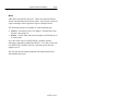
Important User Information
The illustrations, charts, sample programs and layout examples
shown in this guide are intended solely for purposes of example.
Since there are many variables and requirements associated with any
particular installation, Allen-Bradley does not assume responsibility
or liability (to include intellectual property liability) for actual use
based upon the examples shown in this publication.
Allen-Bradley publication SGI-1.1, Safety Guidelines for the
Application, Installation, and Maintenance of Solid-State Control
(available from your local Allen-Bradley office), describes some
important differences between solid-state equipment and
electromechanical devices that should be taken into consideration
when applying products such as those described in this publication.
Reproduction of the contents of this copyrighted publication, in
whole or in part, without written permission of Allen-Bradley
Company, Inc., is prohibited.
Throughout this manual we use notes to make you aware of safety
considerations:
!
ATTENTION: Identifies information about practices
or circumstances that can lead to personal injury or
death, property damage or economic loss.
Attention statements help you to:
• identify a hazard
• avoid the hazard
• recognize the consequences
Important:
Identifies information that is critical for successful
application and understanding of the product.
Table of Contents
Preface
Intended Audience . . . . . . . . . . . . . . . . . . . . . . . . . . . . . . . . . .
Contents of this Manual . . . . . . . . . . . . . . . . . . . . . . . . . . . . . . .
Related Publications . . . . . . . . . . . . . . . . . . . . . . . . . . . . . . . . .
Laser Warning Symbol . . . . . . . . . . . . . . . . . . . . . . . . . . . . . . . .
Chapter 1
P–1
P–2
P–4
P–4
Scanner Features
Scanner Features . . . . . . . . . . . . . . . . . . . . . . . . . . . . . . . . . . . 1–2
LED Indicators . . . . . . . . . . . . . . . . . . . . . . . . . . . . . . . . . . . . . 1–3
Safety Labels . . . . . . . . . . . . . . . . . . . . . . . . . . . . . . . . . . . . . . 1–4
Smart Raster . . . . . . . . . . . . . . . . . . . . . . . . . . . . . . . . . . . . . . 1–5
Scanning Options . . . . . . . . . . . . . . . . . . . . . . . . . . . . . . . . . . . 1–6
Aiming Dot . . . . . . . . . . . . . . . . . . . . . . . . . . . . . . . . . . . . . . 1–6
Slab Raster . . . . . . . . . . . . . . . . . . . . . . . . . . . . . . . . . . . . . . 1–6
Always Raster . . . . . . . . . . . . . . . . . . . . . . . . . . . . . . . . . . . . 1–6
Configuration Options . . . . . . . . . . . . . . . . . . . . . . . . . . . . . . . . 1–7
Decoding . . . . . . . . . . . . . . . . . . . . . . . . . . . . . . . . . . . . . . . . . 1–7
Scanning Ranges . . . . . . . . . . . . . . . . . . . . . . . . . . . . . . . . . . . 1–8
1-D Bar Codes . . . . . . . . . . . . . . . . . . . . . . . . . . . . . . . . . . . 1–8
2-D Bar Codes (PDF417) . . . . . . . . . . . . . . . . . . . . . . . . . . . . 1–10
Accessories . . . . . . . . . . . . . . . . . . . . . . . . . . . . . . . . . . . . . . . 1–11
Publication 2755-6.4
Publication 2755-6.4
toc–ii
Chapter 2
Table of Contents
Connecting the Scanner
Safety . . . . . . . . . . . . . . . . . . . . . . . . . . . . . . . . . . . . . . . . . . .
Overview . . . . . . . . . . . . . . . . . . . . . . . . . . . . . . . . . . . . . . . . .
Scanner Cable Connection . . . . . . . . . . . . . . . . . . . . . . . . . . . .
Scanner Cable to Synapse Cable Connection . . . . . . . . . . . . . . .
Scanner Emulation Synapse Cable Connections . . . . . . . . . . . . .
RS-232 Synapse Cable Connections . . . . . . . . . . . . . . . . . . . . .
Keyboard Wedge Synapse Cable Connections . . . . . . . . . . . . . .
Scanner to Enhanced Decoder Scanner Port Connection . . . . . . .
Scanner to Enhanced Decoder Aux Port Connection . . . . . . . . . .
Scanner to Flexible Interface (RB) Module Connection . . . . . . . . .
Scanner to PLC Connection . . . . . . . . . . . . . . . . . . . . . . . . . . . .
Scanner to SLC Connection . . . . . . . . . . . . . . . . . . . . . . . . . . . .
Chapter 3
2–1
2–2
2–3
2–4
2–5
2–6
2–8
2–10
2–11
2–12
2–13
2–14
Operating the Scanner
Scanning 1-D Bar Codes . . . . . . . . . . . . . . . . . . . . . . . . . . . . . .
Scanning 2-D Bar Codes . . . . . . . . . . . . . . . . . . . . . . . . . . . . . .
Scan the Entire Bar Code Symbol . . . . . . . . . . . . . . . . . . . . . . . .
Specular Reflection . . . . . . . . . . . . . . . . . . . . . . . . . . . . . . . . . .
Dead Zone . . . . . . . . . . . . . . . . . . . . . . . . . . . . . . . . . . . . . . . .
Beeper Indications . . . . . . . . . . . . . . . . . . . . . . . . . . . . . . . . . .
Beeper Indications During Normal Operation . . . . . . . . . . . . . .
Beeper Indications During Configuration . . . . . . . . . . . . . . . . .
Beeper Indications During Communication . . . . . . . . . . . . . . .
Publication 2755-6.4
3–2
3–3
3–4
3–7
3–8
3–9
3–9
3–9
3–9
Table of Contents
Chapter 4
toc–iii
Configuring the Scanner
Important Notes on Configuring Scanner . . . . . . . . . . . . . . . . . . . 4–1
Configuration Bar Codes for Scanner . . . . . . . . . . . . . . . . . . . . . 4–1
Configuring the Scanner . . . . . . . . . . . . . . . . . . . . . . . . . . . . . . 4–2
Scanner Default Settings . . . . . . . . . . . . . . . . . . . . . . . . . . . . . . 4–2
Set Defaults . . . . . . . . . . . . . . . . . . . . . . . . . . . . . . . . . . . . . . . 4–4
Select Symbologies . . . . . . . . . . . . . . . . . . . . . . . . . . . . . . . . . . 4–4
Code 39 Options . . . . . . . . . . . . . . . . . . . . . . . . . . . . . . . . . . . . 4–5
Code 39 Full ASCII . . . . . . . . . . . . . . . . . . . . . . . . . . . . . . . . 4–5
Code 39 Check Digit . . . . . . . . . . . . . . . . . . . . . . . . . . . . . . . 4–5
UPC / EAN Options . . . . . . . . . . . . . . . . . . . . . . . . . . . . . . . . . . 4–6
Transmit UPC-A Check Digit . . . . . . . . . . . . . . . . . . . . . . . . . 4–6
Transmit UPC-E Check Digit . . . . . . . . . . . . . . . . . . . . . . . . . 4–6
Convert UPC-E to UPC-A . . . . . . . . . . . . . . . . . . . . . . . . . . . 4–6
Decode UPC / EAN Supplemental . . . . . . . . . . . . . . . . . . . . . 4–6
Convert EAN-8 to EAN-13 . . . . . . . . . . . . . . . . . . . . . . . . . . . 4–7
UPC-A / UPC-E Preambles . . . . . . . . . . . . . . . . . . . . . . . . . . 4–7
Code Lengths . . . . . . . . . . . . . . . . . . . . . . . . . . . . . . . . . . . . . . 4–8
Any Length . . . . . . . . . . . . . . . . . . . . . . . . . . . . . . . . . . . . . . 4–8
Length Within Range . . . . . . . . . . . . . . . . . . . . . . . . . . . . . . . 4–8
One Discrete Length . . . . . . . . . . . . . . . . . . . . . . . . . . . . . . . 4–8
Two Discrete Lengths . . . . . . . . . . . . . . . . . . . . . . . . . . . . . . 4–8
Data Format Options . . . . . . . . . . . . . . . . . . . . . . . . . . . . . . . . . 4–9
Prefix / Suffix . . . . . . . . . . . . . . . . . . . . . . . . . . . . . . . . . . . . 4–9
Transmit No Read Message . . . . . . . . . . . . . . . . . . . . . . . . . . 4–9
Data Transmission Format . . . . . . . . . . . . . . . . . . . . . . . . . . . 4–10
Transmit LRC Checksum . . . . . . . . . . . . . . . . . . . . . . . . . . . . 4–10
Transmit Code ID Character . . . . . . . . . . . . . . . . . . . . . . . . . . 4–11
Publication 2755-6.4
Publication 2755-6.4
toc–iv
Table of Contents
Decode Options . . . . . . . . . . . . . . . . . . . . . . . . . . . . . . . . . . . .
Beep After Good Decode . . . . . . . . . . . . . . . . . . . . . . . . . . . .
Beeper Tone . . . . . . . . . . . . . . . . . . . . . . . . . . . . . . . . . . . . .
Decode Buffering . . . . . . . . . . . . . . . . . . . . . . . . . . . . . . . . .
Pause Duration . . . . . . . . . . . . . . . . . . . . . . . . . . . . . . . . . . .
Decode Attempt Duration . . . . . . . . . . . . . . . . . . . . . . . . . . . .
Scanning Options . . . . . . . . . . . . . . . . . . . . . . . . . . . . . . . . . . .
Smart Raster Mode . . . . . . . . . . . . . . . . . . . . . . . . . . . . . . . .
Hand-Held Options . . . . . . . . . . . . . . . . . . . . . . . . . . . . . . . .
Chapter 5
4–12
4–12
4–12
4–12
4–12
4–13
4–14
4–14
4–14
Configuring Communications (Synapse Cable)
Cable Defaults . . . . . . . . . . . . . . . . . . . . . . . . . . . . . . . . . . . . .
Setting RS-232 Synapse Cable Options . . . . . . . . . . . . . . . . . . .
Default Settings . . . . . . . . . . . . . . . . . . . . . . . . . . . . . . . . . . .
Host Selection . . . . . . . . . . . . . . . . . . . . . . . . . . . . . . . . . . . .
Baud Rate . . . . . . . . . . . . . . . . . . . . . . . . . . . . . . . . . . . . . .
Parity . . . . . . . . . . . . . . . . . . . . . . . . . . . . . . . . . . . . . . . . . .
Check Parity . . . . . . . . . . . . . . . . . . . . . . . . . . . . . . . . . . . . .
Number of Stop Bits . . . . . . . . . . . . . . . . . . . . . . . . . . . . . . .
Data Bits . . . . . . . . . . . . . . . . . . . . . . . . . . . . . . . . . . . . . . .
Hardware Handshaking . . . . . . . . . . . . . . . . . . . . . . . . . . . . .
RTS State . . . . . . . . . . . . . . . . . . . . . . . . . . . . . . . . . . . . . . .
Software Handshaking . . . . . . . . . . . . . . . . . . . . . . . . . . . . . .
Beep on BEL . . . . . . . . . . . . . . . . . . . . . . . . . . . . . . . . . . . .
Unknown Characters . . . . . . . . . . . . . . . . . . . . . . . . . . . . . . .
Response Timeout . . . . . . . . . . . . . . . . . . . . . . . . . . . . . . . .
Advanced Features . . . . . . . . . . . . . . . . . . . . . . . . . . . . . . . .
Publication 2755-6.4
5–1
5–2
5–2
5–3
5–3
5–4
5–4
5–4
5–4
5–5
5–5
5–6
5–7
5–7
5–7
5–8
Table of Contents
Setting IBM PC Keyboard Wedge Synapse Cable Options . . . . . .
Defaults Settings . . . . . . . . . . . . . . . . . . . . . . . . . . . . . . . . . .
Host Selection . . . . . . . . . . . . . . . . . . . . . . . . . . . . . . . . . . . .
Country Selection . . . . . . . . . . . . . . . . . . . . . . . . . . . . . . . . .
Unknown Characters . . . . . . . . . . . . . . . . . . . . . . . . . . . . . . .
Intercharacter Delay . . . . . . . . . . . . . . . . . . . . . . . . . . . . . . .
Advanced Features . . . . . . . . . . . . . . . . . . . . . . . . . . . . . . . .
Setting DEC VT520 Keyboard Wedge Synapse Cable Options . . .
Default Settings . . . . . . . . . . . . . . . . . . . . . . . . . . . . . . . . . . .
Host Selection . . . . . . . . . . . . . . . . . . . . . . . . . . . . . . . . . . . .
Country Selection . . . . . . . . . . . . . . . . . . . . . . . . . . . . . . . . .
Unknown Characters . . . . . . . . . . . . . . . . . . . . . . . . . . . . . . .
Intercharacter Delay . . . . . . . . . . . . . . . . . . . . . . . . . . . . . . .
Advanced Features . . . . . . . . . . . . . . . . . . . . . . . . . . . . . . . .
Setting DEC VT220/VT320/VT420 Keyboard Wedge
Synapse Cable Options . . . . . . . . . . .
Default Settings . . . . . . . . . . . . . . . . . . . . . . . . . . . . . . . . . . .
Host Selection . . . . . . . . . . . . . . . . . . . . . . . . . . . . . . . . . . . .
Country Selection . . . . . . . . . . . . . . . . . . . . . . . . . . . . . . . . .
Unknown Characters . . . . . . . . . . . . . . . . . . . . . . . . . . . . . . .
Intercharacter Delay . . . . . . . . . . . . . . . . . . . . . . . . . . . . . . .
Advanced Features . . . . . . . . . . . . . . . . . . . . . . . . . . . . . . . .
Setting Scanner Emulation Synapse Cable Options . . . . . . . . . . .
Default Settings . . . . . . . . . . . . . . . . . . . . . . . . . . . . . . . . . . .
Emulation . . . . . . . . . . . . . . . . . . . . . . . . . . . . . . . . . . . . . . .
Variable Leading Margin . . . . . . . . . . . . . . . . . . . . . . . . . . . .
Check for Decode LED . . . . . . . . . . . . . . . . . . . . . . . . . . . . .
Emulation Timeout . . . . . . . . . . . . . . . . . . . . . . . . . . . . . . . .
Polarity . . . . . . . . . . . . . . . . . . . . . . . . . . . . . . . . . . . . . . . . .
Unknown Characters . . . . . . . . . . . . . . . . . . . . . . . . . . . . . . .
Convert All to Code 39 . . . . . . . . . . . . . . . . . . . . . . . . . . . . . .
Code 39 to Code 39 Full ASCII . . . . . . . . . . . . . . . . . . . . . . . .
Advanced Features . . . . . . . . . . . . . . . . . . . . . . . . . . . . . . . .
toc–v
5–9
5–9
5–10
5–10
5–11
5–11
5–12
5–13
5–13
5–14
5–14
5–14
5–15
5–15
5–16
5–16
5–16
5–17
5–17
5–17
5–18
5–19
5–19
5–20
5–20
5–20
5–21
5–21
5–21
5–22
5–22
5–23
Publication 2755-6.4
Publication 2755-6.4
toc–vi
Chapter 6
Table of Contents
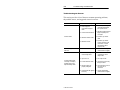
Troubleshooting and Maintenance
Troubleshooting the Scanner . . . . . . . . . . . . . . . . . . . . . . . . . . .
Cleaning the Scan Window . . . . . . . . . . . . . . . . . . . . . . . . . . . .
A-B Technical Support . . . . . . . . . . . . . . . . . . . . . . . . . . . . . . . .
Appendix A Specifications
Appendix B Scanner Pinout Connections
Appendix C ASCII Chart
Appendix D AIM Code Identifiers
Appendix E Advanced Data Formatting
Appendix F European Union Directive Compliance
Glossary
Index
Publication 2755-6.4
6–2
6–4
6–4
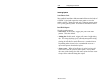
Preface
Read this preface to familiarize yourself with the rest of the manual.
This preface covers the following topics:
• intended audience
• contents of this manual
• related publications
• laser warning symbol
Intended Audience
No special knowledge is required to understand this document or use
the scanner. The 2-D (2-Dimensional) scanner may be used with a
variety of host devices. You should be familiar with the host’s
communication ports.
!
ATTENTION: Use of controls or adjustments or
performance of procedures other than those specified
herein may result in hazardous laser light exposure.
Important: You will need the Programming Guide for 2-D Bar
Code Scanners (Publication 2755-6.7) to scan configuration bar
codes for the scanners.
Publication 2755-6.4
Publication 2755-6.4
P–2
Preface
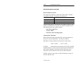
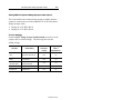
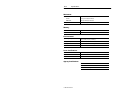
Contents of this Manual
Chapter
Title
Contents
Describes the purpose, background, and
scope of this manual. Also provides a list
of related publications.
Preface
Provides an overview of the scanner.
Includes read range charts and a
description of accessory items.
1
Scanner Features
2
Connecting the Scanner
Describes how to connect your scanner to
system hardware.
3
Operating the Scanner
Describes how to use the scanner to scan
1-Dimensional and 2-Dimensional
bar codes.
4
Configuring the Scanner
Describes how to configure the scanner
using the bar codes in the Programming
Guide for 2-D Scanners.
5
Configuring
Communications
(Synapse Cable)
Describes how to configure the
communication parameters for the
Synapse cable using the bar codes in the
Programming Guide for 2-D Scanners.
6
Maintenance and
Troubleshooting
Describes how to maintain and
troubleshoot your scanner system
hardware.
Appendix A
Specifications
Provides optical, electrical, mechanical
and environmental specifications. Also
lists agency certifications.
Appendix B
Cable Pinouts
Provides scanner pinout signal names and
a brief description of each.
Appendix C
ASCII Table
Publication 2755-6.4
Lists ASCII conversion chart including
Code 39 Full ASCII encoded characters.
Preface
Chapter
Title
Appendix D
AIM Code Identifiers
Appendix E
Advanced Data
Formatting
Appendix F
European Union
Directive Compliance
P–3
Contents
Describes the AIM Code Identifiers that
can be transmitted with decoded data.
Describes how to customize data before it
is transmitted to your host device.
Provides details for using the scanner in
industrial environments requiring
compliance with European Union
Directives.
Provides terms found within this
document.
Glossary
Related Publications
Below is a list of related publications you may need to refer to when
using the 2-D scanners.
Publication No.
Title
2755-6.7
Programming Guide for 2-D Bar Code Scanners
2755-921
Bar Code Basics
Laser Warning Symbol
Be aware of the following laser caution symbol.
CAUTION:
A laser caution symbol that appears
where laser light is present.
Publication 2755-6.4
Publication 2755-6.4
Chapter
1
Scanner Features
This chapter describes the features of the 2-D Bar Code Scanners,
including:
• major features
• LED indicators
• smart raster capability
• scanning options
• configuration options
• decoding options
• scanning ranges
• safety labels
• accessories
Publication 2755-6.4
1–2
Scanner Features
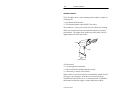
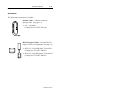
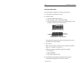
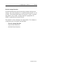
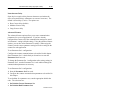
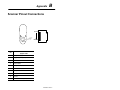
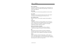
Scanner Features
The 2-D scanner emits a raster scanning pattern which is capable of
scanning both:
• One-dimensional bar codes
• Two-dimensional bar codes (PDF417 bar codes)
The scanners use a low power visible (red) laser diode for scanning,
which can read color bar codes and symbols printed on just about
any substrate. The trigger turns on the laser which scans a label at
approximately 560 scans per second.
LEDs
Trigger
Cable Connector
The laser beam:
• exits through the scan window
• reflects off the label back through the window
• is detected by a sensor in the scanner
When a label is read, the laser beam is automatically turned off until
the trigger is pressed again. If no label is read, the laser beam
automatically turns off after 0.5 to 3 seconds (timeout is adjustable)
and remains off until the trigger is released and pressed again.
Publication 2755-6.4
Scanner Features
1–3
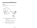
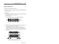
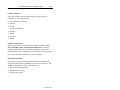
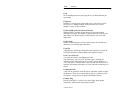
LED Indicators
On the back of the scanner there is a clear window through which
two LEDs are visible.
Green
Red
Green LED = Decode, indicating that a bar code symbol has been
scanned and decoded. LED remains on until the next
scan (trigger pressed).
The scanner indicates a successful decode through an
audible beep and the decocde (Green) LED.
Red LED = Scanning, indicating that the laser light is on and
alignment of the scanner with the bar code.
Publication 2755-6.4
1–4
Scanner Features
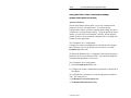
Safety Labels
The scanners use a low power visible laser diode. As with any bright
light source, you should avoid staring directly into the beam.
Momentary exposure to a CDRH Class II laser is not known to be
harmful.
The following figure shows the location of all safety labels as they
appear on the scanner.
LASER LIGHT
DO NOT STARE INTO BEAM
CLASS 2 LASER PRODUCT
680nm LASER
1.0 MILLIWATT MAX OUTPUT
AVOID EXPOSURE
LASER LIGHT IS
EMITTED FROM
THIS APERATURE.
Appears on both sides.
RAYONNEMENT LASER
NE PAS REGARDER DANS LE FAISCEAU
APPAREIL A LASER DE CLASSE 2
LASER–STRAHLUNG
NICHT IN DEN STRAHL BLICKEN !
LASER KLASSE 2
COMPLIES WITH
IEC 825–1:1993/EN 60825
CAUTION – LASER LIGHT WHEN OPEN –
DO NOT STARE INTO BEAM.
ATTENTION – RAYONNEMENT LASER EN
CAS DOUVERTURE. NE PAS REGARDER
DANS LE FAISCEAU
VORSICHT!
LASERSTRAHL, WENN ABDECKUNG GEOEFFNET
Publication 2755-6.4
Scanner Features
1–5
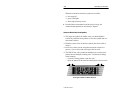
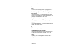
Smart Raster
The scanner has a programmable smart raster capability, which
causes the scanner to emit a raster pattern dynamically adjusted to
the height of a 2-D (PDF417) bar code. To increase scanning
efficiency and decrease decode time, the scanner determines the
height of the bar code and then opens the scan pattern to a size
optimal for decoding the bar code.
In normal smart raster operation, a trigger pull causes a slab raster
pattern to appear. If the target is a 1-D bar code, the pattern never
opens beyond a slab raster.
If the target bar code is a 2-D (PDF417) bar code, the scanning
pattern opens to a full, optimized raster pattern when the scanner is
poperly aligned over the bar code.
The scanner operates with a smart raster capability unless
programmed otherwise.
Aiming Dot Pattern
Slab Raster Pattern
Open Raster Pattern
Publication 2755-6.4
1–6
Scanner Features
Scanning Options
The scanner has 3 scanning options: aiming dot, slab raster and
always raster.
Aiming Dot
A trigger pull creates the single aiming dot pattern, which lasts for a
fixed interval. This dot is easily visible in outdoor or high ambient
light environments. After the aiming dot, a slab raster or open raster
pattern appears, depending on the configured scanning option. You
can select the aiming dot option with either a normal or extended
timeout period.
Slab Raster
A trigger pull creates the slab raster pattern. If the target is a 1-D bar
code, the pattern never opens beyond a slab raster. If the target is a
2-D (PDF417) bar code, the pattern opens to an optimized raster
pattern when the scanner is properly aligned over the bar code.
Always Raster
A trigger pull opens to a full raster pattern.
Publication 2755-6.4
Scanner Features
1–7
Configuration Options
The scanner is adaptable to a wide variety of applications by
scanning configuration bar codes. The configuration bar codes
control the operation of:
• decoding
• scanning
• communications
The 2-D scanner provides full host compatiblility through a Synapse
cable with programmable options.
Chapters 4 and 5 describe the configuration options.
Decoding
The scanner can decode the following symbologies:
• One-Dimensional Bar Codes
– UPC-A, UPC-E
– EAN-8, EAN-13
– Code 39, Code 39 Full ASCII
– Interleaved 2 of 5
– Code 128
– Codabar
– UCC/EAN 128
• Two-Dimensional Bar Codes
– PDF417
The scanner is autodiscriminating so that multiple symbologies may
be enabled at the same time. The only exception is the scanner
cannot discriminate between Code 39 and Code 39 Full ASCII.
Publication 2755-6.4
1–8
Scanner Features
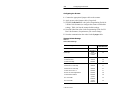
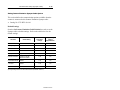
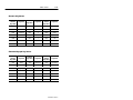
Scanning Ranges
The scanner can read bar code symbols at various distances
depending on the type of bar codes and the bar code width
(width of bars or spaces).
This section show the read ranges for both the:
• 1-D bar codes
• 2-D bar codes
Read Ranges
1-D Bar Codes
Minimum
Bar Code Width
Read Range
(Catalog No. 2755-HTG-4)
Inches / Centimeters
6.0 mil
(.15 mm)
2.0 in to 7.25 in
(5.1 cm to 18.4 cm)
7.5 mil
(.19 mm)
2.0 in to 8.0 in
(5.1 cm to 20.3 cm)
20.0 mil
(.51 mm)
2.25 in to 13.50 in
(5.7 cm to 34.3 cm)
40.0 mil
(1.02 mm)
2.5 in to 22.0 in
(6.35 cm to 55.9 cm)
55.0 mil
(1.40 mm)
2.5 in to 30.0 in
(6.35 cm to 76.2 cm)
Publication 2755-6.4
Scanner Features
1–9
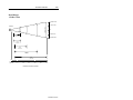
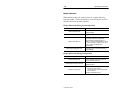
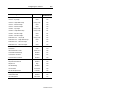
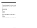
Read Ranges
1-D Bar Codes
10 (25.4 cm)
5 (12.7 cm)
Scan Width
Scanner
0
5 (12.7 cm)
6 mil
(0.15 mm)
10 (25.4 cm)
7.5 mil
(0.19 mm)
20 mil
(0.51 mm)
40 mil
(1.02 mm)
55 mil
(1.40 mm)
0
inches
centimeters
5
12.7
10
25.4
15
38.1
20
50.8
25
63.5
30
76.2
Distance From Front of Scanner
Publication 2755-6.4
1–10
Scanner Features
Read Ranges
2-D Bar Codes (PDF417)
Minimum Bar Code
Width
Read Range
(Catalog No. 2755-HTG-4)
Inches / Centimeters
6.0 mil
(.15 mm)
1.5 in to 5.75 in
(3.8 cm to 14.6 cm)
10.0 mil
(.26 mm)
1.25 in to 8.25 in
(3.2 cm to 21.0 cm)
15.0 mil
(.39 mm)
1.5 in to 11.50 in
(3.8 cm to 29.2 cm)
Read Ranges
2-D Bar Codes
5 (12.7)
2.5 (6.4)
Scan Width
Scanner
0
2.5 (6.4)
5 (12.7)
6 mil
(0.15 mm)
10 mil
(0.26 mm)
15 mil
(0.39 mm)
0
inches
1
centimeters 2.54
2
5.1
4
10.1
6
15.2
8
20.3
Distance From Front of Scanner
Publication 2755-6.4
10
25.4
12
30.5
Scanner Features
1–11
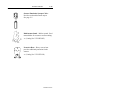
Accessories
The following accessories are available.
Scanner Cable – Connects scanner to
Synapse cable. See page 2–4.
• 8 ft. / 2.44 meter
(Catalog No. 2755-HTC-GS1-08)
RS-232 Synapse Cables – Provides RS-232
output. Cables are configurable. See page 2–6.
• RS-232-C, 25-pin DB, male, Txd on Pin 3
(Catalog No. 2755-HFC-SR2-01)
• RS-232-C, 9-pin DB, female, Txd on Pin 2
(Catalog No. 2755-HFC-SR3-01)
Publication 2755-6.4
1–12
Scanner Features
Power Supplies – Connects to RS-232,
keyboard wedge or scanner emulation
Synapse cable. Provides power to scanner➀.
• 100 - 240 VAC, 50 - 60 Hz
(Catalog No. 2755-HFP-D1)
• Power cable for power supply, IEC 320
terminated, US 110V AC
(Part No. 77121-801-01)
• Power cable for power supply, IEC 320
unterminated, US 240V AC
(Part No. 77121-801-02)
• Power cable for power supply, IEC 320
unterminated, European 240V AC
(Part No. 77121-801-03)
➀ Some applications may not require a power supply if the host provides adequate
power for the scanner. The ability of the host to provide power varies with system
configurations. Scanner with cable requires 390mA at 5 volts (typical).
Keyboard Wedge Synapse Cables –
Connects between keyboard and host device.
Host device receives decoded bar code data
the same as keyboard input. See page 2–8.
• For IBM XT/AT keyboard, 5-pin DIN
(Catalog No. 2755-HFC-SP1-01)
• For PS/2 keyboard, 6-pin Mini-DIN
(Catalog No. 2755-HFC-SP2-01)
• For DEC VT220, 320, 420 keyboards
(Catalog No. 2755-HFC-SV1-01)
• For DEC VT520 keyboards
(Catalog No. 2755-HFC-SV2-01)
Publication 2755-6.4
Scanner Features
1–13
Scanner Emulation Synapse Cable –
Provides undecoded scanner output.
See page 2–5.
Multi-mount Stand – Rubber coated, fixed
mount holder for counter or wall mounting.
• (Catalog No. 2755-HFN-K3)
Protective Boot – Heavy canvas boot
provides additional protection for the
scanner.
• (Catalog No. 2755-HTN-H1)
Publication 2755-6.4
Chapter
2
Connecting the Scanner
This chapter describes how to connect the scanner to various cables
and hardware. Sections include:
• Scanner cable connection
• Scanner Emulation Synapse cable connections
• RS-232 Synapse cable connections
• Keyboard Wedge Synapse cable connections
• Allen-Bradley Enhanced Decoder connection
• Flexible Interface Module (RB) connection
• PLC connection
• SLC connection
Safety
!
ATTENTION: Caution - use of controls or
adjustments or performance of procedures other than
those specified herein may result in hazardous laser
light exposure.
Publication 2755-6.4
2–2
Connecting the Scanner
Overview
The scanner may be connected to a variety of host devices through a
synapse cable. The communication parameters for the cables are
configured by scanning bar codes. The three types of cables are:
• RS-232 Synapse cable
• Keyboard Wedge Synapse cable
• Scanner Emulator Synapse cable
All configuration bar codes are in the Programming Guide for 2-D
Bar Code Scanners.
Publication 2755-6.4
Connecting the Scanner
2–3
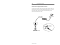
Scanner Cable Connection
The scanner cable (Catalog No. 2755-HTC-GS1-08) connects to the
bottom of the scanner handle. The other end of the scanner cable
connects to the Synapse cable.
Locking Collar
Connector
Cable Connector
Slot for Tab on Collar
To attach the cable to the scanner:
1. Pull back the locking collar from the connector.
2. Insert the cable connector into the scanner.
3. Align the tabs on the locking collar with the slots on the handle.
4. Push in and turn the locking collar counterclockwise to lock.
Connector is locked when flat edge of locking collar aligns with
the front edge of the scanner handle.
Remove a scanner cable from a scanner by rotating the locking collar
clockwise until the cable be pulled out of the scanner.
Publication 2755-6.4
2–4
Connecting the Scanner
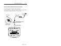
Scanner Cable to Synapse Cable Connection
To connect the scanner cable to a Synapse cable, push the cable into
the connector until you hear the connector snap in place. To remove
the scanner cable, press down on the small raised bump on the
connector end and remove cable.
Scanner
Scanner Cable
Press Here
to Remove
Synapse Cable
(2755-HFC-SR3-01 shown)
Publication 2755-6.4
Connecting the Scanner
2–5
Scanner Emulation Synapse Cable Connections
Use the Scanner Emulation Synapse cable to provide undecoded
output to a scanner input port of a bar code decoder (cable has
female 9-pin DB connector).
Catalog No. 2755-HFC-SA1-01
A separate power supply provides power to the scanner. The power
supply plugs into the Scanner Emulation Synapse cable.
Power Supply
Scanner Cable
Scanner
Scanner Emulation Synapse Cable
(2755-HFC-SA1-01)
Note: Connect the power
supply last.
To Bar Code Decoder
!
ATTENTION: Do not install the Scanner Emulation
Synapse cable with power applied to either the Synapse
cable or decoder. Failure to follow this caution may
result in damage to the scanner, Synapse cable, or
decoder.
Publication 2755-6.4
2–6
Connecting the Scanner
RS-232 Synapse Cable Connections
Use the RS-232 Synapse cable to connect the scanner to any host
RS-232C input port. Two types of RS-232 Synapse cables are
available:
Catalog No. 2755-HFC-SR2-01
Catalog No. 2755-HFC-SR3-01
RS-232 Synapse
Cable
Output Connector
Output Signal
2755-HFC-SR2-01
Male 25-pin DB
RS-232C, Txd on Pin #3
2755-HFC-SR3-01
Female 9-pin DB
RS-232C, Txd on Pin #2
!
ATTENTION: Do not install the RS-232 Synapse
cable with power applied to either the Synapse cable or
host device. Failure to follow this caution may result
in damage to the scanner, Synapse cable, or host
device.
Publication 2755-6.4
Connecting the Scanner
2–7
Connect the scanner to an RS-232 port as shown below. A separate
power supply provides power to the scanner. The power supply
plugs into the RS-232 Synapse cable.
Scanner
Scanner Cable
Power Supply
RS-232 Synapse Cable
(2755-HFC-SR3-01 shown)
Note: Connect the
power supply last.
To Host RS-232 Port
Host with RS-232 Port
Publication 2755-6.4
2–8
Connecting the Scanner
Keyboard Wedge Synapse Cable Connections
Use the Keyboard Wedge Synapse cable to connect the scanner
between a keyboard and a host device. The host device interprets the
decoded scanner output the same as keyboard data. Four types of
Keyboard Wedge Synapse cables are available:
Catalog No. 2755-HFC-SP1-01
Catalog No. 2755-HFC-SP2-01
Catalog No. 2755-HFC-SV1-01
Catalog No. 2755-HFC-SV2-01
Keyboard Wedge
Synapse Cable
For Keyboard Type:
2755-HFC-SP1-01
IBM AT/XT Keyboard (5-pin DIN)
2755-HFC-SP2-01
PS/2 Keyboard (6-pin Mini-DIN)
2755-HFC-SV1-01
DEC VT220/320/420
2755-HFC-SV2-01
DEC VT520
A separate power supply plugs into the Synapse cable and provides
power to the scanner. The following wedge cable applications may
not require the power supply if the host provides adequate power for
the scanner (depends on system configuration):
• IBM PC/AT
• IBM PS / 2-50, 55SX, 60, 70, 80
• IBM PC/XT and compatibles
• IBM PS/2-30
Publication 2755-6.4
Connecting the Scanner
Power Supply
(May not be required,
see previous page.)
2–9
Scanner
Scanner Cable
Wedge Synapse Cable
(2755-HFC-SP1-01 shown)
Note: Connect the
power supply last.
To Host
Keyboard Connector
To Keyboard
To connect the scanner cable to the keyboard wedge cable, push the
cable into the connector until you hear the connector snap in place.
To remove the scanner cable, press down on the small raised bump
on the connector end and remove cable.
!
ATTENTION: Do not install the wedge cable or
disconnect/connect the keyboard with power applied to
either the wedge cable or host device. Failure to
follow this caution may result in damage to the
scanner, wedge interface cable, or host device.
The Wedge Synapse cable connects between the keyboard and the
host device. Unplug the keyboard and connect one end of the wedge
cable to the host keyboard input. Connect the other end of the wedge
interface cable to the keyboard.
Publication 2755-6.4
2–10
Connecting the Scanner
Scanner to Enhanced Decoder Scanner Port Connection
Use the Scanner Emulation Synapse cable (Catalog No.
2755-HFC-SA1-01) and Gun Adapter (Catalog No. 2755-NC16,
Series B) to connect the scanner cable to a scanner port on the
Allen-Bradley Enhanced Decoders (2755-DS1/DD1).
Scanner
Power Supply
Scanner Cable
Scanner Emulation Synapse Cable
(2755-HFC-SA1-01)
Note: Connect the
power supply last.
Gun Adapter
(Catalog No. 2755-NC16)
Allen-Bradley Enhanced Decoder
(2755-DS1/DD1)
Publication 2755-6.4
Connecting the Scanner
2–11
Scanner to Enhanced Decoder Aux Port Connection
Use the 25-pin RS-232 Synapse cable (Catalog No.
2755-HFC-SR2-01) to connect the scanner cable to Aux port on the
Allen-Bradley Enhanced Decoders (2755-DS1/DD1).
Scanner
Scanner Cable
Power Supply
25-pin RS-232 Synapse Cable
(2755-HFC-SR2-01)
Note: Connect the
power supply last.
Null Modem Adapter
Allen-Bradley Enhanced Decoder
(2755-DS1/DD1)
Publication 2755-6.4
2–12
Connecting the Scanner
Scanner to Flexible Interface (RB) Module Connection
Use the 25-Pin RS-232 Synapse cable (Catalog No.
2755-HFC-SR2-01) to connect the scanner cable to a port on the
Flexible Interface Module (Catalog No. 2760-RB). The protocol
cartridges (Catalog No. 2760-SFC1, -SFC2) support RS-232
communications.
Scanner
Scanner Cable
Power Supply
RS-232 Synapse Cable
(2755-HFC-SR2-01)
Note: Connect the
power supply last.
SFC1, SFC2 Protocol Cartridge
To RB Module Communications Port
Flexible Interface Module
Refer to the user manual for the Flexible Interface Module for the
proper configuration. Make sure the Synapse cable communications
settings match the Flexible Interface Module settings for the port.
Publication 2755-6.4
Connecting the Scanner
2–13
Scanner to PLC Connection
Use the 25-Pin RS-232 Synapse cable (Catalog No.
2755-HFC-SR2-01) to connect the scanner cable to the Channel 0
port of a PLC-5. The Channel 0 port must be configured for RS-232
communications.
Scanner
Power Supply
Scanner Cable
RS-232 Synapse Cable
(2755-HFC-SR2-01)
Note: Connect the
power supply last.
PLC-5
To Channel 0 Port
Refer to the user manuals for the Allen-Bradley 6200 Series
Programming Software to make sure the Channel 0 settings match
the Synapse cable settings.
Publication 2755-6.4
2–14
Connecting the Scanner
Scanner to SLC Connection
Use the 9-Pin RS-232 Synapse cable (Catalog No.
2755-HFC-SR3-01) to connect the scanner cable to the Channel 0
port on an SLC-5/03 or 5/04. The Channel 0 port must be
configured for RS-232 communications.
Scanner
Scanner Cable
Power Supply
RS-232 Synapse Cable
(2755-HFC-SR3-01)
Note: Connect the
power supply last.
SLC 5/04
To Channel 0 Port
Channel 0
Refer to the user manuals for the Allen-Bradley Advanced
Programming Software (APS) to make sure the Channel 0 settings
match the Synapse cable settings.
Publication 2755-6.4
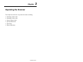
Chapter
3
Operating the Scanner
This chapter describes how to operate the scanner, including:
• Scanning 1-D bar codes
• Scanning 2-D bar codes
• Scan the Entire Label
• Specular Reflection
• Dead Zone
• Beeper Indications
Publication 2755-6.4
3–2
Operating the Scanner
Scanning 1-D Bar Codes
Any scan pattern is adequate for scanning 1-D bar codes.
1. Verify that all connections are secure.
2. Aim the scanner.
• Aim the scanner at the bar code.
• Press the trigger. The red LED should light.
• For proper orientation, while using a scanning pattern, center
the beam on the bar code as shown below.
Aiming Dot on Code 39 Bar Code
Slab Raster Pattern on a Code 39 Bar Code
If you hold the scanner in a position which makes the bar code
unreadable, the red LED blinks.
3. Scan a label.
Make sure the symbol you want to scan is within the scanning
range (3 to 11 inches). See page 1–8.
When the scanner has decoded a symbol successfully:
• laser turns off
• green LED lights
• short, high-tone beep occurs
4. Decoded data is transmitted to the host device using the
communication parameters described in Chapter 5.
Publication 2755-6.4
Operating the Scanner
3–3
Scanning 2-D Bar Codes
1. Verify that all connections are secure.
2. Aim the scanner. Try to keep the nose of the scanner parallel with
the symbol’s rows.
3. Scan a label.
• Make sure the symbol you want to scan is within the scanning
range (3 to 8 inches). See page 1–10.
• Press the trigger.
The scan pattern first covers the symbol horizontally.
Slab Raster Pattern on a PDF417 Bar Code
• Make sure the scan pattern extends at least three quarters of
an inch beyond the edges of the bar code.
If the pattern is parallel to the symbol’s rows, the pattern
spreads vertically to cover the symbol. If the pattern does not
cover the top and bottom of the symbol, pull the scanner back
until it does.
3/4”
3/4”
Scan Pattern Spreading over PDF417 Bar Code
Publication 2755-6.4
3–4
Operating the Scanner
When the scanner has decoded a symbol successfully:
• laser turns off
• green LED lights
• short, high-tone beep occurs
4. Decoded data is transmitted to the host device using the
communication parameters described in Chapter 5.
Scan the Entire Bar Code Symbol
• The larger the symbol, the farther away you should hold the
scanner to permit the raster pattern to cover the symbol (but not
more than 8 inches).
• Hold the scanner close for denser symbols (but not less than 2
inches).
• In all cases, make sure the scan pattern extends at least three
quarters of an inch beyond each edge of the bar code.
• The PDF417 bar code symbol has multiple rows, but the raster
pattern also has multiple scanning rows. Do three basic things
when scanning:
– Center the aiming pattern on the bar code.
– Keep the pattern in the same horizontal plane as the bar code.
3/4”
3/4”
Orienting Scan Pattern on PDF417 Bar Code
Publication 2755-6.4
Operating the Scanner
3–5
– The vertical scan pattern is not high enough to cover a tall
PDF417 symbol. Move the scanner slowly down toward the
bottom of the symbol, keeping the beam horizontal to the
rows, and then slowly back upward toward the top.
Moving Scan Pattern Up and Down on Tall PDF Symbol
– The scan beam does not have to be perfectly parallel with the
top and bottom of the symbol (up to a 4_ tilt will work).
Publication 2755-6.4
3–6
Operating the Scanner
Specular Reflection
When the laser beam reflects directly back into the scanner from the
decode, it can blind the scanner and make decoding difficult. This is
called specular reflection.
To avoid this, scan the bar code so that the beam does not bounce
directly back. Do not scan at too oblique an angle; the scanner needs
to collect scattered reflections from the scan to make a successful
decode. Simple practice shows what tolerances to work within.
Tilt Back at Slight Angle (up to 30_)
Bar Code
1. Specular reflection; reflected
beam interferes.
Bar Code
2. No specular reflection. Decode
can occur.
Avoiding Specular Reflection
Publication 2755-6.4
Operating the Scanner
3–7
Dead Zone
When scanning a 1-D bar code, there is only a small specular dead
zone to avoid (+2_ from the direct laser beam). The specular dead
zone is larger when scanning PDF417 (+9_ from the direct laser
beam). At the same time, the scanner is not effective if its beam hits
the bar code’s surface at an angle greater than 30_ from normal to
that surface.
1. Successful Scanning
2. Successful Scanning
Tilted 0_ – 30_ back from surface
Tilted 20_ – 50_ forward toward surface
0_ – 30_
Scan Beam
20_ – 50_
Normal
Scan Beam
Right Angle
Bar Code
Angles for Good Decodes
You can also scan successfully by tilting the scanner forward from
parallel about 20_ to 50_ toward the scanning surface.
Publication 2755-6.4
3–8
Operating the Scanner
Beeper Indications
When scanning a bar code symbol, listen for a single, short beep
from the scanner. This beep indicates a successful decode. Refer to
the tables below for all other responses.
Beeper Indications During Normal Operation
This Response
Indicates
1 Beep (short high tone)
Bar code symbol decoded. Beeper Tone
must be enabled.
1 Beep (long high tone)
Thermal shutdown.
3 Beeps (short high tone)
4 Beep (high/high/high/high tone)
Power-on or reset. Occurs immediately after
the scanner is turned on, indicating the
system software is working properly. If 3
beeps occur during normal operation, it is due
to a reset; any work in progress is lost. If this
occurs, contact your Allen-Bradley
representative.
Low battery power. A trill sound following a
decode attempt.
Beeper Indications During Configuration
This Response
Indicates
1 Beep (short high tone)
Correct configuration bar code scanned or
correct sequence performed.
1 Beep (high / low / high / low tone)
Exited configuration mode without changing
parameter setting.
2 Beeps (low / high tone)
Publication 2755-6.4
Input error. Possible causes are:
Incorrect bar code scanned.
Incorrect sequence of bar codes scanned.
Cancel scanned.
Remain in configuration mode.
Operating the Scanner
3–9
Beeper Indications During Communication
This Response
4 Beeps (short high tone)
4 Beeps (high / high / high / low tone)
3 Beeps (low / high / low tone)
Indicates
Communication error in the indication field.
Receive error.
ADF transmit error.
Publication 2755-6.4
Chapter
4
Configuring the Scanner
This chapter describes the scanner configuration options.
Important Notes on Configuring Scanner
• Bar codes for configuring the scanner and Synapse cable are
located in the Programming Guide for 2-D Bar Code Scanners
(Publication 2755-6.7).
• Configure the scanner.
• Configure the Synapse cable. Separate configuration codes are
scanned to configure the cable.
Chapter 5 describes the communication setup (cable
configuration) codes for the RS-232, keyboard wedge cable,
scanner emulation.
Configuration Bar Codes for Scanner
All configuration bar codes are found in the Programming Guide for
2-D Bar Code Scanners (Publication 2755-6.7). The scanner is
always enabled to read Code 128 configuration bar codes since all
configuration codes use this symbology.
Publication 2755-6.4
4–2
Configuring the Scanner
Configuring the Scanner
1. Connect the appropriate Synapse cable to the scanner.
2. Apply power to the Synapse cable (if required).
3. Scan the Set Defaults bar code (in the Programming Guide for
2-D Bar Code Scanners) to configure the scanner with default
settings. Table 4.A lists the scanner default settings.
4. Scan individual bar codes (in the Programming Guide for 2-D
Bar Code Scanners) for parameters you want to change.
5. Scan the communication bar codes for the Synapse cable.
Scanner Default Settings
Table 4.A
Scanner Default Settings
Configuration Parameters
Default Setting
Programming
Guide Reference
1-1
Set Default
Set Defaults
Symbologies
All Enabled,
except
I 2 of 5, and
Codabar
1-3
Code 39 Full ASCII
Enabled
1-6
Code 39 Check Digit
Disabled
1-6
Transmit UPC-A Check Digit
Enabled
1-7
Transmit UPC-E Check Digit
Enabled
1-7
Convert UPC-E to UPC-A
Disabled
1-7
Decode UPC / EAN Supplemental
Disabled
1-8
Convert EAN-8 to EAN-13
Disabled
1-8
UPC-A Preamble
System
Character
1-9
UPC-E Preamble
System
Character
1-9
Code 39 Options
UPC/EAN Options
Publication 2755-6.4
Configuring the Scanner
Configuration Parameters
4–3
Default Setting
Programming
Guide Reference
None
1-10
Code Lengths
Code 39 – Any Length
Code 39 – Length Within Range
Range (1-55)
1-10
Code 39 – 1 Discrete Length
None
1-10
Code 39 – 2 Discrete Lengths
None
1-10
Codabar – Any Length
Range (2-55)
1-11
Codabar – Length Within Range
Range (2-55)
1-11
Codabar – 1 Discrete Length
None
1-11
Codabar – 2 Discrete Lengths
None
1-11
Range (2-54)
1-12
Interleaved 2 of 5 – Any Length
Interleaved 2 of 5 – Length Within Range
None
1-12
Interleaved 2 of 5 – 1 Discrete Length
14
1-12
Interleaved 2 of 5 – 2 Discrete Lengths
None
1-12
Enter
1-14
Data Transmission Format
<Data> As Is
1-16
Transmit No Read Message
Disabled
1-17
Transmit LRC Checksum
Disabled
1-17
Transmit Code ID Character
Disabled
1-18
Enabled
1-19
High
1-19
Data Format Options
Prefix/Suffix
Decode Options
Beep After Good Decode
Beeper Tone
Decode Buffering
Disabled
1-19
0.0 seconds
1-20
5 seconds
1-20
Smart Raster Mode
Enabled
1-22
Hand-Held Options
Slab Raster
1-22
Pause Duration
Decode Attempt Duration
Scanning Options
Publication 2755-6.4
4–4
Configuring the Scanner
Set Defaults
Scan the Set Defaults bar code to return all parameters to the default
values listed in Table 4.A.
Select Symbologies
Scan the bar code labels for the symbologies you want the scanner to
decode. Only enable the symbologies you expect to read. The
scanner automatically discriminates between all of the symbologies
below. The only exception is that the scanner cannot discriminate
between Code 39 and Code 39 Full ASCII.
•
•
•
•
•
•
•
UPC Versions A and E (EAN 8 and 13)
Code 39 (Code 39 Full ASCII)
Codabar
UCC/EAN 128
Interleaved 2 of 5
Discrete 2 of 5
PDF417
By default, all symbologies are enabled except Interleaved 2 of 5 and
Codabar.
To enable a symbology, scan the Enable bar code for the symbology.
To disable a symbology, scan the Disable bar code. You can enable
all code types (only Code 39 Full ASCII is disabled).
Publication 2755-6.4
Configuring the Scanner
4–5
Code 39 Options
Code 39 Full ASCII
The ASCII character set assigns a code to letters, punctuations
marks, numerals, and most control keystrokes on the keyboard.
The first 32 codes are non-printable and are assigned to keyboard
control keys, such as Backspace and Return. The other 96 are
called printable codes because all but Space and Delete produce
visible characters.
Code 39 Full ASCII interprets the bar code control characters ($ + %
/) preceding a Code 39 symbol and assigns an ASCII character value.
For example, when +B is scanned, it is interpreted as b, %J as ?, and
$H emulates the keystroke BACKSPACE. Scanning ABC$M
outputs the keystroke equivalent ABC ENTER.
Refer to Appendix C for a list of the Code 39 Full ASCII codes.
The scanner cannot autodiscriminate between Code 39 and Code 39
Full ASCII symbols.
Code 39 Check Digit
When enabled, this parameter checks the integrity of a Code 39
symbol to ensure that is complies with specified algorithms.
Publication 2755-6.4
4–6
Configuring the Scanner
UPC / EAN Options
The section defines options available for UPC-A and UPC-E codes.
Transmit UPC-A Check Digit
When enabled, UPC-A symbol data is transmitted with the check
digit. Enabled is the default.
Transmit UPC-E Check Digit
When enabled, UPC-E symbol data is transmitted with the check
digit. Enabled is the default.
Convert UPC-E to UPC-A
When enabled, this option converts UPC-E (zero suppressed)
decoded data to a UPC-A format before transmission. After
conversion, the output data follows UPC format and follows UPC-A
programming selections (e.g., preamble, check digit). Disabled is
the default.
Decode UPC / EAN Supplemental
The options for decoding UPC/EAN supplemental digits are:
• Enabled – supplemental digits are decoded (2 or 5 according to
specific code format conventions, e.g., UPC A+2, UPC E+2,
EAN 8+2). Only symbols with supplemental digits are decoded.
• Disabled – supplemental digits are ignored even if present.
Disabled is the default.
• Autodiscriminate – codes with and without supplemental digits
are decoded.
To minimize the risk of invalid data transmission, we recommend
that you select whether to read or ignore supplemental characters.
Publication 2755-6.4
Configuring the Scanner
4–7
UPC / EAN Options (Continued)
Convert EAN-8 to EAN-13
When enabled, five leading zeros are added to decoded EAN 8
symbols. The five zeros make the EAN 8 symbols compatible with
the EAN 13 format. Disabled is the default.
UPC-A / UPC-E Preambles
Three options are available for the lead-in characters of decoded
UPC-A or UPC-E symbols transmitted to the host device. Select one
preamble for UPC-A decodes and one for UPC-E decodes. The
preamble is considered a part of the symbol. The three options are:
• system character only
• country code and system character
• no preamble
The system character is the the first character on the left side of the
symbol. The country code for UPC is always 0, and cannot be
transmitted without the system character. System character is the
default.
Publication 2755-6.4
4–8
Configuring the Scanner
Code Lengths
The length of a code refers to the number of characters (human
readable characters) the code contains. You can set the code length
for certain one-dimensional code types (Code 39, Codabar,
Interleaved 2 of 5) to any length, one or two disrete lengths, or
lengths within a specific range. You cannot set a discrete length for
Code 128.
Any Length
Select this option to decode a one-dimensional code containing any
number of characters. For example, to scan a Codabar symbol
containing any number of characters, scan Codabar Any Length.
Length Within Range
Select this option to decode a one-dimensional code containing a
length within a specified range. For example, to decode Code 39
codes containing between 4 and 12 characters, scan the Code 39
Length Within Range code. Then scan, 0, 4, 1, 2. Single digit
numbers must be preceded with a zero.
One Discrete Length
Select this option to decode only one-dimensional codes containing a
selected length. For example, to decode Codabar codes containing
14 characters, scan Codabar – One Discrete Length. Then scan 1
and 4.
Two Discrete Lengths
Select this option to decode only one-dimensional codes containing
two selected lengths. For example, to decode Interleaved 2 of 5
codes containing 2 or 14 characters, scan Interleaved 2 of 5 – Two
Discrete Lengths. Then scan 0, 2, 1, 4. Single digit numbers must
be preceded with a zero.
Publication 2755-6.4
Configuring the Scanner
4–9
Data Format Options
Prefix / Suffix
You can add a prefix/suffix to bar code data. To enter a prefix/suffix,
you must scan a four digit number (four bar codes) that represents
the ASCII equivalent value for each character (See ASCII Characters
in Appendix C). When you enter the last digit of a prefix or suffix,
the scanner lets you know that you have entered a valid value by
providing a high-low-high beep.
The default prefix/suffix is the ENTER key (ASCII equivalent
1073).
For example, to add the prefix < (ASCII equivalent 1060) to bar
code data, scan these labels:
–
–
–
–
–
Prefix
1 (under Prefix/Suffix Values)
0 (under Prefix/Suffix Values)
6 (under Prefix/Suffix Values)
0 (under Prefix/Suffix Values)
For example, to add the suffix > (ASCII equivalent 1062) to bar code
data, scan these labels:
–
–
–
–
–
Suffix
1 (under Prefix/Suffix Values)
0 (under Prefix/Suffix Values)
6 (under Prefix/Suffix Values)
2 (under Prefix/Suffix Values)
Transmit No Read Message
When enabled, this option transmits “NR” when a symbol does not
decode. Enabled prefixes and suffixes are appended around this
message. The default is disabled.
Publication 2755-6.4
4–10
Configuring the Scanner
Data Format Options (continued)
Data Transmission Format
You can specify whether or not the prefix and/or suffix is added to
decoded bar code data. The options are listed below.
<Data>
Sends only bar code data.
<Prefix><Data>
Sends bar code data with a prefix
<Data><Suffix>
Sends bar code data with a suffix
<Prefix><Data><Suffix>
Sends bar code data with a prefix and suffix
The prefix and suffix are user defined. For example, the prefix [ and
suffix ] are defined for bar code data. To send the decoded bar code
data with the prefix only, scan these labels:
– Scan This Symbol First
– <Prefix><Data>
– Scan Enter After Selecting Option
Transmit LRC Checksum
When enabled, this option appends an LRC checksum character at
the end of a decode transmission. The default is disabled.
With LRC Checksum enabled, the format of the output data is:
<STX> <DATA . . . > <ETX> <LRC> .
If <DATA . . . > contains the special characters STX, ETX, and DLE,
the DLE character is used as an escape character and is added before
each of those characters so that the receiving side knows not to
interpret the special characters in the data as control characters.
The LRC character is the exclusive OR of all characters except for
the LRC character itself.
Publication 2755-6.4
Configuring the Scanner
4–11
Transmit Code ID Character
When enabled, this option transmits a code ID character or an AIM
ID character to identify the code type of the symbol scanned. This
option is useful if you are scanning more than one code type. If a
prefix is defined, the code ID character is sent after the prefix and
before the decoded symbol. The default is to not transmit a Code ID
character.
Code ID characters are listed below. AIM ID characters are listed in
Appendix D.
Code Type
Code Identifier (ID)
UPC-A, UPC-E, EAN-13, EAN-8
A
Code 39
B
Codabar
C
Code 128
D
Code 93
E
Interleaved 2 of 5
F
Discrete 2 of 5, D 2 of 5 IATA
G
UCC/EAN 128
K
PDF417
X
Publication 2755-6.4
4–12
Configuring the Scanner
Decode Options
Beep After Good Decode
When enabled, the beeper sounds during scanning. We recommend
that you operate the unit with the beeper enabled. The default is
enabled.
The beeper always operates during parameter menu scanning and
indicates error conditions. See page 3–8 for beeper indications.
Beeper Tone
Sets the decode beep frequency or tone to low, medium or high. The
default is high.
Decode Buffering
When enabled, this option allows the scanner to store decoded data
until the host device is ready to receive them. If the scanner reaches
its capacity for storing decoded symbols before the host is ready,
subsequent triggers have no effect until the buffer is available. The
default is disabled.
Pause Duration
This parameter inserts a pause after a bar code is scanned to allow
time for the data to be decoded and transferred to the host. You can
set a pause duration in .1 (1/10) second intervals from 0.1 to 9.9
seconds. Pauses are set by scanning a two digit number. The default
is 0.0 seconds.
For example, to set a .5 (1/2) second delay, scan the following labels:
– Pause Duration
– 0 (under Pause Duration)
– 5 (Under Pause Duration)
Publication 2755-6.4
Configuring the Scanner
4–13
Decode Attempt Duration
Sets the maximum time decode processing continues during a scan
attempt. You set the duration in .1 second increments from 0.1 to 9.9
seconds. The recommended interval is between 1.0 and 5.0 seconds.
The default is 5.0 seconds. A longer interval is appropriate for
PDF417 symbols that are hard to decode.
The duration is set by scanning a two digit number. For example, to
set the interval to 6.0 seconds, scan the labels:
– Decode Attempt Duration
– 6 (under Pause Duration)
– 0 (Under Pause Duration)
Publication 2755-6.4
4–14
Configuring the Scanner
Scanning Options
Smart Raster Mode
When enabled, Smart Raser Mode automatically detects the height of
the PDF417 symbol and expands the raster pattern to cover the
symbol vertically. Change this mode only if the raster pattern cannot
cover a poorly printed symbol. The default is Smart Raster enabled.
Hand–Held Options
Select the scanning pattern.
• Slab raster – In this mode, a trigger pull yields a slab raster
pattern. This is the default.
• Aiming dot – In this mode, a trigger pull creates a bright aiming
dot. The aiming dot helps you to center the pattern while aiming
the scanner, especially in bright light conditions. You can select
aiming dot with either a normal timeout or an extended timeout.
Depending on the selected option, a standard slab raster or an
open raster appears when the dot expires.
• Always raster – When Always Raster is enabled, a trigger pull
causes the scanner to open a full raster pattern. Always Raster
does not exclude aiming dot or slab raster options because a raster
always follows when the aiming dot expires.
Publication 2755-6.4
Chapter
5
Communication Setup (Synapse
Cable)
This chapter describes how to configure scanner communication
parameters. The types of options available depends on the synapse
cable you are using.
For This Cable:
See These Pages:
RS-232 Synapse Cables
5–2 through 5–8
IBM PC Keyboard Wedge Synapse Cables
5–9 through 5–12
DEC VT520 Keyboard Wedge Synapse Cable
5–13 through 5–15
DEC VT220, VT320, VT420 Keyboard Wedge Synapse Cable
5–16 through 5–18
Scanner Emulation Synapse Cable
5–19 through 5–23
Important: All programming codes are located in the
Programming Guide for 2-D Bar Code Scanners (Publication
2755-6.7).
Cable Defaults
To set cable defaults, scan the default label for the synapse cable you
are using. Refer to each cable section for a table listing the defaults.
The selections for cable defaults are:
•
•
•
•
Set RS-232 Synapse Cable Defaults
Set IBM PC Keyboard Wedge Synapse Cable Defaults
Set DEC VT 520 Keyboard Wedge Synapse Cable Defaults
Set DEC VT VT220, VT320, VT420 Wedge Synapse Cable
Defaults
Publication 2755-6.4
5–2
Communication Setup (Synapse Cable)
Setting RS-232 Synapse Cable Options
This section defines the communication options available when the
scanner is connected to one of these RS-232 Synapse cables:
• Catalog No. 2755-HFC-SR2-01
• Catalog No. 2755-HFC-SR3-01
Default Settings
Scanning the Set RS-232 Synapse Cable Defaults bar code sets the
following parameters:
Parameter
Default Setting
Refer to
Description
on Page:
Programming
Guide ➀
Page Reference
Host
Standard RS-232
5–3
2-3
Baud Rate
9600
5–3
2-4
Parity
None
5–4
2-5
Check Parity
Enabled
5–4
2-6
Stop Bits
1
5–4
2-6
Data Bits
8
5–4
2-6
Hardware
Handshaking
None
5–5
2-7
RTS State
Low
5–5
2-7
Software
Handshaking
None
5–6
2-8
Beep on BEL
Enabled
5–7
2-9
Unknown Characters Send Bar Codes With
Unknown Characters
5–7
2-9
Response Timeout
2 seconds
5–7
2-10
Parameter Set
Set #1
5–8
2-12
➀ Programming Guide for 2-D Bar Code Scanners (Publication 2755-6.7).
Publication 2755-6.4
Communication Setup (Synapse Cable)
5–3
Host Selection
Currently, the only host selection is for standard RS-232
communications. Additional host selections may be added in the
future.
• Standard RS-232 (default)
Baud Rate
Sets the rate (bits per second) at which the scanner transmits data.
The scanner baud rate setting must match the host setting.
The selections are:
•
•
•
•
•
•
•
•
110
300
600
1200
2400
4800
9600 (default)
19200
Publication 2755-6.4
5–4
Communication Setup (Synapse Cable)
Setting RS-232 Synapse Cable Options (Continued)
Parity
Set the parity of each ASCII coded character that is transmitted.
Make sure the parity matches the requirements of the host. The
selections are:
•
•
•
•
•
Odd
Even
Mark (parity bit always set to 1)
Space (parity bit always set to 0)
None (default)
Check Parity
When enabled, the scanner checks the parity bit.
Number of Stop Bits
The stop bit marks the end of each character transmitted. Set the
number of stop bits to match the host device. The selections are:
• 1 Stop Bit (default)
• 2 Stop Bits
Data Bits
Determines the number of data bits for each ASCII character. The
selections are:
• 7 data bits
• 8 data bits (default)
Publication 2755-6.4
Communication Setup (Synapse Cable)
5–5
Hardware Handshaking
When enabled, handshaking verifies the readiness of a receiving
device before data is transmitted. You can enable or disable the
hardware handshaking lines. The DTR (Data Terminal Ready)
signal is either active high or low (see below).
This is how the scanner handshaking functions:
1. The scanner checks the Clear to Send (CTS) line. If CTS is
active, the scanner will wait for up to 2 seconds and check the
line again. If the line is still active, the scanner will provide an
audible beep and any scanned data will be lost.
2. If the CTS line is not active, the scanner will assert the Request to
Send (RTS) line and wait for two seconds for the host to assert
the CTS line. When the host asserts the CTS line, the scanner
transmits the data.
3. After the transmission is completed, the scanner negates the RTS.
4. The host device should then negate CTS. The scanner checks the
CTS line on the next transmission.
RTS State
Selects the active state for the Request to Send (RTS) signal.
Make sure that this setting matches the requirements of the host
device. The selections are:
• RTS State Low (default)
• RTS State High
Publication 2755-6.4
5–6
Communication Setup (Synapse Cable)
Setting RS-232 Synapse Cable Options (Continued)
Software Handshaking
Software handshaking controls the transmission of data. Use
software handshaking instead of (but not with) hardware
handshaking. The four options are:
•
•
•
•
•
None (default)
ACK/NAK Only
ENQ Only
ACK/NAK with ENQ
XON/XOFF
ACK/NAK Only checks the result of a transmission. The scanner
waits for one of two response from the host: ACK which means a
successful transmission or NAK which means there was a problem.
Whenever the scanner receives a NAK, it retransmits the data up to
three times. If an ACK is still not received after three attempts, the
transmission is aborted and the scanner will provide four short beeps.
ENQ Only requires that the scanner receive an enquire character
(ENQ) from the host before sending data. With ENQ enabled, the
scanner must receive an ENQ from the host within a two second
period after the last scan or a transmission error occurs. The scanner
will provide four short beeps to indicate the error.
ACK/NAK with ENQ combines both ACK/NAK and ENQ options.
With XON/ XOFF enabled, the Synapse cable assumes an XON for
the first transmission. The scanner will transmit data until an XOFF
is received from the host device. If an XON is not received within
30 seconds after an XOFF, a transmission error occurs.
Publication 2755-6.4
Communication Setup (Synapse Cable)
5–7
Beep on BEL
When enabled, the scanner will beep when a <BEL> character is
detected on the RS-232 link. <BEL> may be used to indicate an
event such as an illegal entry.
Unknown Characters
Unknown characters are characters not recognized by the scanner.
When Send Bar Codes with Unknown Characters is enabled, all
decoded bar code data is transmitted except for the unknown
characters. If this option is disabled, bar codes containing one or
more unknown characters are not transmitted.
Response Timeout
The response timeout determines the maximum amount of time the
scanner will wait before it assumes the end of a transmission. The
timeout period may be from 0.0 to 9.9 seconds in 0.1 second
increments. The default is 2.0 seconds.
To enter a new timeout, scan the timeout label followed by the two
digit timeout. The decimal point is fixed between the first and
second digits.
Publication 2755-6.4
5–8
Communication Setup (Synapse Cable)
Setting RS-232 Synapse Cable Options (Continued)
Advanced Features
The advanced feature options allow you to store communication
parameters for up to two applications. If you have already
configured the scanner, all of the communication settings are stored
as Parameter 1 settings (default setting). Using the advanced feature
options, you can also create Parameter 2 settings. When using the
scanner, scan the correct parameter setting bar code to configure the
scanner for each application.
To set Parameter Set 1 configuration:
Configure the scanner communications as described in this chapter.
Since Parameter Set 1 is the default you do not have to scan the
Parameter Set 1 bar code.
To change the Parameter Set 1 configuration after storing settings in
Parameter Set 2, scan the Parameter Set 1 code and then change the
communication parameters as necessary.
To set Parameter Set 2 configuration:
1. Scan the Parameter Set 2 bar code.
2. Configure the scanner communication parameters as described in
this chapter.
To set defaults for a parameter set, scan the appropriate default bar
code. The selections are:
• Set Cable Defaults Current Parameter Set
• Set Cable Defaults Both Parameter Sets
Publication 2755-6.4
Communication Setup (Synapse Cable)
5–9
Setting IBM PC Keyboard Wedge Synapse Cable Options
This section defines the communication options available when the
scanner is connected to one of these IBM AT/XT or PS/2 Keyboard
Wedge Synapse cables:
• Catalog No. 2755-HFC-SP1-01
• Catalog No. 2755-HFC-SP2-01
Defaults Settings
Scan the Set PC Wedge Synapse Cable Defaults bar code to set the
synapse cable to default settings. The following table lists the
default settings.
Refer to
Description
on Page:
Programming
Guide ➀
Page Reference
IBM PC/AT
IBM PS/2-50, 55SX, 60, 70,
80
5–10
3-2
Country
North American
5–10
3-3
Bar Codes with
Unknown Labels
Send Bar Codes With
Unknown Characters
5–11
3-4
Intercharacter Delay
5 milliseconds
5–11
3-4
Parameter Set
Parameter Set 1
5–12
3-5
Parameter
Host
Default Setting
➀ Programming Guide for 2-D Bar Code Scanners (Publication 2755-6.7)
Publication 2755-6.4
5–10
Communication Setup (Synapse Cable)
Setting IBM PC Keyboard Wedge
Synapse Cable Options (Continued)
Host Selection
Select the type of host the scanner will be communicating with.
The selections are:
•
•
•
•
IBM PC/AT , PS/2-50, 55SX, 60, 70, 80 (default)
IBM PC/XT
IBM PS/2-30
NCR 7052
Country Selection
Select the country for the keyboard type the synapse cable is
connected to. The selections are:
•
•
•
•
•
•
•
•
North American (default)
German
French
French International
Spanish
Italian
Swedish
British
Publication 2755-6.4
Communication Setup (Synapse Cable)
5–11
Unknown Characters
Unknown characters are characters not recognized by the scanner.
When Send Bar Codes with Unknown Characters is enabled
(default), all decoded bar code data is transmitted except for the
unknown characters. If this option is disabled, bar codes containing
one or more unknown characters are not transmitted.
Intercharacter Delay
Setting an intercharacter delay provides the host time to perform
processing tasks between characters. The default is short delay (5
msec). The options are:
• Short 5 msec delay (default)
• Medium 50 msec delay
• Long 99 msec delay
Publication 2755-6.4
5–12
Communication Setup (Synapse Cable)
Setting IBM PC Keyboard Wedge
Synapse Cable Options (Continued)
Advanced Features
The advanced feature options allow you to store communication
parameters for up to two applications. If you have already
configured the scanner, all of the communication settings are stored
as Parameter 1 settings (default setting). Using the advanced feature
options, you can also create Parameter 2 settings. When using the
scanner, scan the correct parameter setting bar code to configure the
scanner for each application.
To use and/or set Parameter Set 1 configuration:
Configure the scanner communications as described in this chapter.
Since Parameter Set 1 is the default you do not have to scan the
Parameter Set 1 bar code.
To change the Parameter Set 1 configuration after storing settings in
Parameter Set 2, scan the Parameter Set 1 code and then change the
communication parameters as necessary.
To use and/or set Parameter Set 2 configuration:
1. Scan the Parameter Set 2 bar code.
2. Configure the scanner communication parameters as described in
this chapter.
To set defaults for a parameter set, scan the appropriate default bar
code. The selections are:
• Set Cable Defaults Current Parameter Set
• Set Cable Defaults Both Parameter Sets
Publication 2755-6.4
Communication Setup (Synapse Cable)
5–13
Setting DEC VT520 Keyboard Wedge Synapse Cable Options
This section defines the communication options available when the
scanner is connected to this DEC Keyboard Wedge Synapse cable:
• Catalog No. 2755-HFC-SV2-01
Default Settings
Scan the Set DEC VT 520 Keyboard Wedge Synapse Cable
Defaults bar code to set the Synapse cable to default settings. Refer
to the table below for the default settings.
Parameter
Default Setting
Refer to
Description
on Page:
Programming
Guide➀
Page Reference
Host
DEC VT520
5–14
4-2
Country
North American
5–14
4-2
Unknown Characters
Send Bar Codes With
Unknown Characters
5–14
4-4
Intercharacter Delay
5 Millisecond
5–14
4-4
Parameter Set
Parameter Set 1
5–15
4-5
➀ Programming Guide for 2-D Bar Code Scanners (Publication 2755-6.7)
Publication 2755-6.4
5–14
Communication Setup (Synapse Cable)
Setting DEC VT520 Keyboard Wedge
Synapse Cable Options (Continued)
Host Selection
Select the type of host the scanner will be communicating with.
The selections are:
• DEC VT520 (default)
• DEC VT520 with PS/2 Keyboard
Country Selection
Select the country for the keyboard type the Synapse cable is
connected to. The selections are:
•
•
•
•
•
•
•
•
North American (default)
German
French
French International
Spanish
Italian
Swedish
British
Unknown Characters
Unknown characters are characters not recognized by the scanner.
When Send Bar Codes with Unknown Characters is enabled
(default), all decoded bar code data is transmitted except for the
unknown characters. If this option is disabled, bar codes containing
one or more unknown characters are not transmitted.
Publication 2755-6.4
Communication Setup (Synapse Cable)
5–15
Intercharacter Delay
Some devices require a delay between characters to simulate the
effect of keystroke delays (characters are sent at a lower rate). The
default is short delay (5 msec). The options are:
• Short 5 msec delay (default)
• Medium 50 msec delay
• Long 99 msec delay
Advanced Features
The advanced feature options allow you to store communication
parameters for up to two applications. If you have already
configured the scanner, all of the communication settings are stored
as Parameter 1 settings (default setting). Using the advanced feature
options, you can also create Parameter 2 settings. When using the
scanner, scan the correct parameter setting bar code to configure the
scanner for each application.
To set Parameter Set 1 configuration:
Configure the scanner communications as described in this chapter.
Since Parameter Set 1 is the default you do not have to scan the
Parameter Set 1 bar code.
To change the Parameter Set 1 configuration after storing settings in
Parameter Set 2, scan the Parameter Set 1 code and then change the
communication parameters as necessary.
To set Parameter Set 2 configuration:
1. Scan the Parameter Set 2 bar code.
2. Configure the scanner communication parameters as described in
this chapter.
To set defaults for a parameter set, scan the appropriate default bar
code. The selections are:
• Set Defaults Current Parameter Set
• Set Defaults Both Parameter Sets
Publication 2755-6.4
5–16
Communication Setup (Synapse Cable)
Setting DEC VT220 / VT320 / VT420 Keyboard Wedge
Synapse Cable Options
This section defines the communication options available when the
scanner is connected to this DEC Keyboard Wedge Synapse cable:
• Catalog No. 2755-HFC-SV1-01
Default Settings
Scan the Set DEC VT 20/320/420 Wedge Synapse Cable Defaults
bar code to set the Synapse cable to default settings. The table below
lists the defaults.
Parameter
Default Setting
Refer to
Description
on Page:
Programming
Guide ➀
Page Reference
Host
DEC VT220 / 320
5–16
5-2
Country
North American
5–17
5-2
Unknown Characters
Send Bar Codes With
Unknown Characters
5–17
5-4
Intercharacter Delay
5 Millisecond
5–17
5-4
Parameter Set
Parameter Set 1
5–18
5-5
➀ Programming Guide for 2-D Bar Code Scanners (Publication 2755-6.7)
Host Selection
Select the type of host the scanner will be communicating with.
The selections are:
• DEC VT 220/320 (default)
• DEC VT420
Publication 2755-6.4
Communication Setup (Synapse Cable)
5–17
Country Selection
Select the country for the keyboard type the Synapse cable is
connected to. The selections are:
•
•
•
•
•
•
•
•
North American (default)
German
French
French International
Spanish
Italian
Swedish
British
Unknown Characters
Unknown characters are characters not recognized by the scanner.
When Send Bar Codes with Unknown Characters is enabled
(default), all decoded bar code data is transmitted except for the
unknown characters. If this option is disabled, bar codes containing
one or more unknown characters are not transmitted.
Intercharacter Delay
Some devices require a delay between characters to simulate the
effect of keystroke delays (characters are sent at a lower rate). The
default is short delay (5 msec). The options are:
• Short 5 msec delay (default)
• Medium 50 msec delay
• Long 99 msec delay
Publication 2755-6.4
5–18
Communication Setup (Synapse Cable)
Setting DEC VT220 / VT320 / VT420 Keyboard Wedge
Synapse Cable Options (Continued)
Advanced Features
The advanced feature options allow you to store communication
parameters for up to two applications. If you have already
configured the scanner, all of the communication settings are stored
as Parameter 1 settings (default setting). Using the advanced feature
options, you can also create Parameter 2 settings. When using the
scanner, scan the correct parameter setting bar code to configure the
scanner for each application.
To set Parameter Set 1 configuration:
Configure the scanner communications as described in this chapter.
Since Parameter Set 1 is the default you do not have to scan the
Parameter Set 1 bar code.
To change the Parameter Set 1 configuration after storing settings in
Parameter Set 2, scan the Parameter Set 1 code and then change the
communication parameters as necessary.
To set Parameter Set 2 configuration:
1. Scan the Parameter Set 2 bar code.
2. Configure the scanner communication parameters as described in
this chapter.
To set defaults for a parameter set, scan the appropriate default bar
code. The selections are:
• Set Defaults Current Parameter Set
• Set Defaults Both Parameter Sets
Publication 2755-6.4
Communication Setup (Synapse Cable)
5–19
Setting Scanner Emulation Synapse Cable Options
This section defines the communication options available when the
scanner is connected to this Scanner Emulation Synapse cable:
• Catalog No. 2755-HFC-SA1-01
Default Settings
Scan the Set Scanner Emulation Cable Defaults bar code to set the
Synapse cable to default settings. Refer to the table below for the
default settings.
Parameter
Default Setting
Refer to
Description
on Page:
Programming
Guide➀
Page Reference
Emulation
Standard
5–20
6-2
Leading Margin
80 Millisecond
5–20
6-3
Decode LED
Enabled
5–20
6-3
Emulation Timeout
3 Seconds
5–21
6-4
Polarity
Margin Low / Bar High
5–21
6-5
Unknown Characters
Send Bar Codes with
Unknown Characters
5–21
6-5
Convert All to Code 39
Disabled
5–22
6-6
Code 39 to Code 39
Full ASCII
Disabled
5–22
6-6
Parameter Set
Parameter Set 1
5–23
6-7
➀ Programming Guide for 2-D Bar Code Scanners (Publication 2755-6.7)
Publication 2755-6.4
5–20
Communication Setup (Synapse Cable)
Setting Scanner Emulation Synapse Cable Options (Continued)
Emulation
Select the type of emulation your decoder requires.
The selections are:
•
•
•
•
Standard Emulation (default)
MSI Wand Emulation
Texlon Wand Emulation
Norand Wand Emulation
Variable Leading Margin
Sets the leading margin for wand emulation. The leading margin can
be varied to allow more time for the decoder to wake up before the
bar code data is received. The selections are:
• 80 msec (default)
• 140 msec
• 200 msec
Check for Decode LED
When enabled (default), a transmission error occurs if the decode
LED line from the host is not active.
Publication 2755-6.4
Communication Setup (Synapse Cable)
5–21
Emulation Timeout
Determines how long:
• the Synapse cable waits for the laser on signal from the scanner
after the trigger is pulled.
• the scanner waits for a decode LED (check if Decode LED is
enabled).
The options:
•
•
•
•
•
3 second timeout (default)
4 second timeout
5 second timeout
10 second timeout
30 second timeout
Polarity
Sets the polarity of the wand emulation signal. The selections are:
• Margin Low / Bar High (default)
• Margin High / Bar Low
Unknown Characters
Unknown characters are characters not recognized by the scanner.
When Send Bar Codes with Unknown Characters is enabled, all
decoded bar code data is transmitted except for the unknown
characters. If this option is disabled, bar codes containing one or
more unknown characters are not transmitted.
Publication 2755-6.4
5–22
Communication Setup (Synapse Cable)
Setting Scanner Emulation Synapse Cable Options (Continued)
Convert All to Code 39
When enabled, decoded data is converted and transmitted as Code 39
data.
Note: ASCII from the scanner is transmitted as Code 39 data.
Code 39 to Code 39 Full ASCII
When enabled, Code 39 data is transmitted as Code 39 Full ASCII.
The full ASCII option allows the scanner to output any ASCII
character or control code (including non-printable characters). Refer
to Appendix C for a list of the Code 39 Full ASCII codes.
Publication 2755-6.4
Communication Setup (Synapse Cable)
5–23
Advanced Features
The advanced feature options allow you to store communication
parameters for 2 separate applications. If you have already
configured the scanner, all of the communication settings are stored
as Parameter 1 settings (default setting). Using the advanced feature
options, you can also create Parameter 2 settings. When using the
scanner, scan the correct parameter setting bar code for each
application.
To select and/or set Parameter Set 1 configuration:
Configure the scanner communications as described in this chapter.
Since Parameter Set 1 is the default you do not have to scan the
Parameter Set 1 bar code.
To change the Parameter Set 1 configuration after storing settings in
Parameter Set 2, scan the Parameter Set 1 code and then change the
communication parameters as necessary.
To set Parameter Set 2 configuration:
1. Scan the Parameter Set 2 bar code.
2. Configure the scanner communication parameters as described in
this chapter.
To select and/or set defaults for a parameter set, scan the appropriate
default bar code. The selections are:
• Set Defaults Current Parameter Set
• Set Defaults Both Parameter Sets
Publication 2755-6.4
Chapter
6
Troubleshooting and Maintenace
This chapter describes how to troubleshoot and maintain the scanner.
• troubleshooting chart
• cleaning the scan window
• Allen-Bradley Global Technical Support
Publication 2755-6.4
6–2
Troubleshooting and Maintenace
Troubleshooting the Scanner
This section provides a list of the most common operating problems,
the probable causes, and suggested corrective actions.
Problem
Probable Cause(s)
1. Power supply not
connected to Synapse
cable.
1. Make sure power supply is
connected and plugged
into a power source.
2. Scan beam has timed out.
2. Normal operation. Release
trigger completely and
scan again.
3. Defective interface cable.
3. If possible, try another
cable.
4. Defective scanner.
4. If possible, try another
scanner using the same
connections. Contact
Allen-Bradley Global
Support (GTS).
1. Defective scanner.
1. Contact Allen-Bradley
Global Technical Support.
1. Scanner not configured for
correct wedge cable.
1. Make sure scanner is
configured for correct
wedge cable.
2. Caps lock is on.
2. Turn Caps lock off.
3. Incorrect interface cable.
3. Check that you are using
the proper cable.
4. Decoder options not
properly configured.
4. Check all options such as
UPC-E to UPC-A
conversion.
5. Scanned data still appears
incorrectly.
5. Contact Allen-Bradley
Global Technical Support.
No Scan Beam.
Scan Beam Appears as a Dot
Not a line
Scanned data appears
incorrectly on a display
terminal when using a
keyboard wedge cable.
Publication 2755-6.4
Corrective Action
Troubleshooting and Maintenace
Problem
Scan Beam Present,
Symbols Not Read
Data is decoded but not
transmitted to host.
6–3
Probable Cause(s)
Corrective Action
1. Scanner not set to decode
symbol type scanned.
1. Verify the scanner decoder
settings.
2. Scanner not held at slight
angle to symbol.
2. Hold scanner at an angle
to the symbol.
3. Scan beam not crossing
entire symbol.
3. Make sure scan beam
crosses every bar and
space on the symbol.
4. Poor quality bar code
symbols.
4. Use the symbols provided
on the inside back cover
for testing.
5. Loose cable connections.
5. Check for loose cable
connections.
6. Incorrect interface cable.
6. Check that you are using
the proper cable.
1. Scanner is not configured
for the proper cable.
1. Make sure the scanner is
configured for the correct
cable (standard RS-232 or
smart cable).
2. Loose connections
2. Check all cable
connections.
3. Scanner communication
settings do not match host
requirements.
3. Verify cable
communication settings
such as baud rate.
Publication 2755-6.4
6–4
Troubleshooting and Maintenace
Cleaning the Scan Window
You may need to clean the window of the scanner. Carefully clean
the window by first removing loose particles of dirt with clean air.
Then use an optical quality cloth moistened with an optical quality
cleaning fluid for plastic lenses and wipe the window in a single
direction (don’t wipe cloth back and forth across window). Do not
leave streaks.
!
!
ATTENTION: Do not use abrasive materials such as
disposable wipes and facial tissue. Do not use solvents
like alcohol or acetone. These materials will damage
the window or the finish on the scanner.
ATTENTION: The scanner has no serviceable parts.
Do not open the housing of the scanner.
A-B Technical Support
If you should require assistance or need additional information on
operating the scanner or Allen-Bradley decoder, contact
Allen-Bradley Global Technical Services (GTS) at (216) 646-6800.
Publication 2755-6.4
Appendix
A
Specifications
Optical
Scan Pattern
Start Time
Pattern Size
0.065 sec. to 75% of steady state horizontal amplitude;
0.50 sec. to 90% of steady state vertical amplitude
At 9.5 in. (24.13 cm) from the nose of the scanner, the
pattern is 7.2 in. (18.3 cm) horizontally and 2.4 in. (6.1
cm ) vertically.
Scan Rate
560 scans/second 280 Hz 10 horizontal
Frame Rate
25 frames/second 12.5 Hz 1 horizontal
Optical Resolution
Can decode a 6.6 mil (minimum X-dimension) symbol
(PDF417); Y-dimension must be 3X.
Angular Orientation Tolerances
Pitch Tolerance
30_ front-to-back
Skew
15_ from plane parallel to symbol (side-to-side)
Rotational Tolerance
4_ (for scanning benchmark label, assuming 3:1
codeword aspect ratio)
Dead Zone/Optical Throw
1-D Labels
2_ from beam direction
2-D (PDF417) Labels
9_ from beam direction
Print Contrast Resolution
1-D Labels
2-D (PDF417) Labels
Ambient Light Immunity
25% absolute dark/light reflectance differential,
measured at 675 nm.
35% absolute dark/light reflectance differential,
measured at 675 nm.
8000 ft. candles (86,112 lux) of sunlight
Electrical
Laser Diode Power
1.2 mW, maximum
Power Requirements
+5V dc, 390 mA (typical)
A–2
Specifications
Mechanical
Dimensions
Inches
4.4 (L) x 2.5 (W) x 6.72 (H)
Millimeters
112 (L) x 64 (W) x 170 (H)
Weight
9.0 oz (252 g) without scanner cable
Memory
RAM
64K, 128K or 256K
Flash
256K
Environmental
Operating Temperature
-20_ to 40_C (-4_ to 104_F)
Storage Temperature
-40_ to 60_C (-40_ to 140_F)
Humidity
5% to 95% (noncondensing)
Shock
5ft (1.5 meter) to concrete
Laser Certifications
CDRH
Class II laser product
IEC
825 Class II
FCC
Class A
Agency Certifications
UL Listed
CSA Listed
CE marked for all applicable directives
Publication 2755-6.4
Appendix
B
Scanner Pinout Connections
Pin #1
Pin #10
Function
Synapse Cable
Pin
1
+5V power supply
2
Trigger Signal output/input
3
Transmit (TxD)
4
Receive (RxD)
5
Ready to Send (RTS)
6
Clear to Send (CTS)
7
Synapse Control Data
8
Synapse Control Clock
9
Ground
10
Data Terminal Ready (DTR)
Publication 2755-6.4
Appendix
C
ASCII Chart
This appendix lists:
•
•
•
•
•
ASCII chart
ALT key values
Miscellaneous key values
Numeric key values
Numeric Keypad key values
ASCII
Value
Full ASCII
Code 39
Encode
Char.
Character
(Control Code)
ASCII
Value
Full ASCII
Code 39
Encode
Char.
Character
(Control Code)
1000
%U
NULL (CTRL 2)
1016
$P
DLE (CTRL P)
1001
$A
SOH (CTRL A)
1017
$Q
DC1 (CTRL Q)
1002
$B
STX (CTRL B)
1018
$R
DC2 (CTRL R)
1003
$C
ETX (CTRL C)
1019
$S
DC3 (CTRL S)
1004
$D
EOT (CTRL D)
1020
$T
DC4 (CTRL T)
1005
$E
ENQ (CTRL E)
1021
$U
NAK (CTRL U)
1006
$F
ACK (CTRL F)
1022
$V
SYN (CTRL V)
1007
$G
BEL (CTRL G)
1023
$W
ETB (CTRL W)
1008
$H
BS (CTRL H)
1024
$X
CAN (CTRL X)
1009
$I
HT (CTRL I)
1025
$Y
EM (CTRL Y)
1010
$J
LF (CTRL J)
1026
$Z
SUB (CTRL Z)
1011
$K
VT (CTRL K)
1027
%A
ESC (CTRL[)
1012
$L
FF (CTRL L)
1028
%B
FS (CTRL \)
1013
$M
CR (CTRL M)
1029
%C
GS (CTRL ])
1014
$N
SO (CTRL N)
1030
%D
RS (CTRL 6)
1015
$O
SI (CTRL O)
1031
%E
US (CTRL –)
Publication 2755-6.4
C–2
ASCII Chart
ASCII
Value
Full ASCII
Code 39
Encode
Char.
Character
ASCII
Value
Full ASCII
Code 39
Encode
Char.
Character
1032
SP
SP
1057
9
9
1033
/A
!
1058
/Z
:
1034
/B
”
1059
%F
;
1035
/C
#
1060
%G
<
1036
/D
$
1061
%H
=
1037
/E
%
1062
%I
>
1038
/F
&
1063
%J
?
1039
/G
‘
1064
%V
@
1040
/H
(
1065
A
A
1041
/I
)
1066
B
A
1042
/J
*
1067
C
C
1043
/K
+
1068
D
D
1044
/L
,
1069
E
E
1045
-
-
1070
F
F
1046
.
.
1071
G
G
1047
/
/
1072
H
H
1048
0
0
1073
I
I
1049
1
1
1074
J
J
1050
2
2
1075
K
K
1051
3
3
1076
L
L
1052
4
4
1077
M
M
1053
5
5
1078
N
N
1054
6
6
1079
O
O
1055
7
7
1080
P
P
1056
8
8
1081
Q
Q
Publication 2755-6.4
ASCII Chart
ASCII
Value
Full ASCII
Code 39
Encode
Char.
1082
C–3
Character
ASCII
Value
Full ASCII
Code 39
Encode
Char.
Character
R
R
1105
+I
i
1083
S
S
1106
+J
j
1084
T
T
1107
+K
k
1085
U
U
1108
+L
l
1086
V
V
1109
+M
m
1087
W
W
1110
+N
n
1088
X
X
1111
+O
o
1089
Y
Y
1112
+P
p
1090
Z
Z
1113
+Q
q
1091
%K
[
1114
+R
r
1092
%L
\
1115
+S
s
1093
%M
]
1116
+T
t
1094
%N
^
1117
+U
u
1095
%O
_
1118
+V
v
1096
%W
‘
1119
+W
w
1097
+A
a
1120
+X
x
1098
+B
b
1121
+Y
y
1099
+C
c
1122
+Z
z
1100
+D
d
1123
%P
{
1101
+E
e
1124
%Q
|
1102
+F
f
1125
%R
}
1103
+G
g
1126
%S
~
1104
+H
h
1127
Undefined
Publication 2755-6.4
C–4
ASCII Chart
ALT Key Values
ALT Key
Value
Keystroke
ALT Key
Value
Keystroke
ALT Key
Value
Keystroke
2064
ALT 2
2075
ALT K
2086
ALT V
2065
ALT A
2076
ALT L
2087
ALT W
2066
ALT B
2077
ALT M
2088
ALT X
2067
ALT C
2078
ALT N
2089
ALT Y
2068
ALT D
2079
ALT O
2090
ALT Z
2069
ALT E
2080
ALT P
2091
ALT [
2070
ALT F
2081
ALT Q
2092
ALT \
2071
ALT G
2082
ALT R
2093
ALT ]
2072
ALT H
2083
ALT S
2094
ALT 6
2073
ALT I
2084
ALT T
2095
ALT -
2074
ALT J
2085
ALT U
Keystroke
Miscellaneous Key Values
Misc. Key
Value
Keystroke
Misc. Key
Value
Keystroke
Misc. Key
Value
3001
PA 1
3009
CMD 7
3017
_
3002
PA 2
3010
CMD 8
3018
1/
2
3003
CMD 1
3011
CMD 9
3019
W
3004
CMD 2
3012
CMD 10
3020
w
3005
CMD 3
3013
O
3021
|
3006
CMD 4
3014
o
3022
0/00
3007
CMD 5
3015
h
3008
CMD 6
3016
–
Publication 2755-6.4
ASCII Chart
C–5
Numeric Key Values
Numeric
Key Value
Keystroke
Numeric
Key Value
Keystroke
Numeric
Key Value
Keystroke
6042
*
6049
1
6056
8
6043
+
6050
2
6057
9
6044
Undefined
6051
3
6058
Enter
6045
–
6052
4
6059
Num Lock
6046
.
6053
5
6060
00
6047
/
6054
6
6048
0
6055
7
Extended Keyapd Key Values
Numeric
Key Value
Keystroke
Numeric
Key Value
Keystroke
Numeric
Key Value
Keystroke
7001
Break
7008
Backspace
7015
Up Arrow
7002
Delete
7009
Tab
7016
Down Arrow
7003
Page Up
7010
Print Screen
7017
Left Arrow
7004
End
7011
Insert
7018
Right Arrow
7005
Page Down
7012
Home
7019
Back Tab
7006
Pause
7013
Enter
7007
Scroll Lock
7014
Escape
Publication 2755-6.4
Appendix
D
AIM Code Identifiers
Each AIM Code Identifier contains the 3-character string ]cm where:
]
=
Flag Character (ASCII 93)
c
=
Code Character (see table below)
m
=
Modifier (see table on next pages)
Code Character /
Generic Identifier
Code Type
A / ]A0
Code 39
C / ]C0
Code 128
E / ]E0
UPC/EAN
I / ]I0
Interleaved 2 of 5
L / ]L0
PDF417
The modifier character is the sum of the applicable option values
based on the following table.
Code Type
Code 39
Option Value
Option
0
1
2
No Check character or Full ASCII processing.
Reader has checked one check character.
Reader has stripped check character.
Reader has performed Full ASCII character
conversion.
A Full ASCII bar code 1234 with check character
W, A+I+MI+DW, can be transmitted as
]A71234 where 7 = (1+2+4).
4
Example:
Publication 2755-6.4
D–2
AIM Code Identifiers
Code Type
Option Value
0
1
Code 128
2
Example:
0
EAN/UPC
1
2
4
Example:
0
1
Interleaved
2 of 5
2
Example:
Option
Standard data packet. No Function code 1 in first
symbol position.
Function code 1 in first symbol character position.
Function code 1 in second symbol character
position.
A Code (EAN) 128 bar code 1234 with Function 1
character in the first position, Fcnt112345 will
transmitted as ]C112345.
Standard packet in full EAN country code format,
which is 13 digits for UPC-A and UPC-E (not
including supplemental data).
Two digit supplement data only.
Five digit supplement data only.
EAN-8 data packet.
A UPC-A bar code 012345678905 will be
transmitted as ]E00012345678905.
No check digit processing.
Reader has checked check digit.
Reader has stripped check digit before
transmission.
An I 2 of 5 bar code without check digit, 4123 will
be transmitted as ]I04123.
According to AIM standards, a UPC with supplemental bar code is
transmitted in one of the following formats:
]E0 (UPC chars) (terminator) ]E2 (supplemental) (terminator) or
]E2 (supplemental) (terminator) ]E0 (UPC chars) (terminator)
In the 2755-HTG-4, however, this format is changed to:
]E0 (UPC chars) ]E2 (supplemental)
Therefore, a UPC with two supplemental characters,
01234567890510, will be transmitted as a 21-character string
]E00012345678905]E110.
Publication 2755-6.4
Appendix
E
Advanced Data Formatting
Advanced Data Formatting (ADF) provides a way to customize data
before transmitting it to a host device. Scan data can be edited to
meet your particular requirements. Topics in this appendix include:
•
•
•
•
•
•
•
•
•
Rules
Programming a Rule
Criteria
Actions
ADF Formatting Example
Alternate Rule Sets
Default Rules
Rules Hierarchy (in Bar Codes)
Beeper Definitions
Publication 2755-6.4
E–2
Advanced Data Formatting
ADF can be implemented by scanning a related series of bar codes,
which appear in the Programming Guide (Publication 2755-6.7).
The table below references the page location of the ADF bar codes.
ADF Bar Codes
Page
Special Commands
Start/Save Rule
A-2
Erase/Quite Rule
A-3
Disable Rule Sets
A-4
Criteria
Code Types
A-5
Code Lengths
A-7
Specific Data String / Numeric Keypad
A-10
Rule Belongs to Set
A-13
Actions
Send Characters/Data
A-14
Skip Ahead/Back
A-18
Spaces and Zeros
A-22
Send Value
A-23
Beeps
A-24
Pad Spaces
A-25
Pad Zeros
A-29
Send Control Characters
A-33
Send Keyboard Characters
A-37
AlphaNumeric Keyboard
A-49
Turn on Rule Set
A-60
Publication 2755-6.4
Advanced Data Formatting
E–3
Rules
ADF data is customized using rules. These rules perform detailed
actions when the data meets certain criteria. One rule may consist of
single or multiple criteria applied to single or multiple actions.
The following describes an example of a data formatting rule:
• Criteria – Scan data is Code 39, Length 12, and data at the start
position is the string 129.
• Actions – Pad all sends with zeros to length 8, send all data up to
X, send a space.
If a Code 39 bar code of 1299X1559828 is scanned, then the
following is transmitted: 00001299<SPACE>. If a Code 39 bar code
of 1299X15598 is scanned, this rule is ignored because the code
length is not 12.
The rule specifies the editing conditions and requirements before
data transmission occurs.
Publication 2755-6.4
E–4
Advanced Data Formatting
Programming a Rule
When programming a rule, the rule must follow a specific format.
Plan ahead before you start scanning.
To program each data formatting rule:
• Start the Rule. Scan the Start New Rule bar code.
• Criteria. Scan the bar codes for all pertinent criteria.
Criteria can include code type (e.g., Code 128), code length, or
data that contains a specific character string (e.g., the digits 129).
These options are described in the Criteria section.
• Actions. Scan all actions related to, or affecting, these criteria.
The actions of a rule specify how to format the data for
transmission. These options are describe in the Actions section.
• Save the Rule. Scan the Save Rule bar code. This places the rule
in the top position in the rule buffer.
• If you make errors during this process, the following bar codes
may be use useful:
– Erase Criteria and Start Again
– Erase Actions and Start Again
– Erase Previously Saved Rule
The table on pages E–13 and E–14 provides beeper indications to
help guide you through the programming steps.
Publication 2755-6.4
Advanced Data Formatting
E–5
Criteria
Code Types
Select any number of code types to be affected. All selected codes
must be scanned in succession, prior to selecting other criteria. If
you don’t select a code type, all code types will be ignored.
Code Length
Define the number of characters the selected code type must contain.
If you don’t select a code length, selected code types of any length
will be affected.
Message Containing a Specific Data String
Select whether the formatting will affect data that begins with a
specific character or data string, or contains a specific character or
data string.
• Specific String at Start – Scan this bar code, than scan the
desired character or characters (up to 8) from the Alphanumeric
Keyboard bar codes.
• Specific String Any Location – Scan this bar code, then, using
the the Numeric Keypad bar codes, scan a 2-digit number
representing the position (using a leading zero if necessary). Then
scan the desired characters (up to 8) on the Alphanumeric
Keyboard, followed by the End of Message bar code.
• Any Message OK – By not scanning any bar code, all selected
code types will be formatted, regardless of information contained.
Publication 2755-6.4
E–6
Advanced Data Formatting
Actions
Select how to format the data for transmission.
• Send Data – Send all data that follows, send all data up to a
specific character selected from the Alphanumeric Keyboard
bar codes, or send the next N characters. N= any number from 1
to 254, selected from the Alphanumeric Keyboard.
• Setup Fields – Define fields as follows:
– Move Cursor To Character – Scan this bar code, then any
–
–
–
–
–
printable ASCII character from the Alphanumeric
Keyboard. The cursor moves to the position after the
matching character. If the character is not there, the rule fails
and ADF tries the next rule.
Move Cursor to Start – Scan this bar code to move cursor to
the beginning of the data.
Move Cursor to Position “N” – Scan this bar code, then
select the position to which you want to move (1 to 254) from
the Numeric Keypad bar codes.
Move Cursor Ahead “N” Positions – Scan this bar code,
then select the number of positions ahead you want to move (0
to 254) from the Numeric Keypad bar codes.
Move Cursor Back “N” Positions – Scan this bar code, then
select the number of positions back you want to move (0 to
254) from the Numeric Keypad bar codes.
Move Cursor Past Character – This parameter will move
the cursor past all occurrences of a selected character. Scan
this bar code, then select a character from the Alphanumeric
Keyboard bar codes. If the character is not there, the cursor
does not move (has no affect).
Publication 2755-6.4
Advanced Data Formatting
E–7
• Send Keystroke – Scan the Send “___ ” bar code for the
keystroke you want to send.
• Send Preset Value – Send Values 1 through 6 by scanning the
appropriate bar code. These values must be set using the Scan
Prefix or Scan Suffix bar codes located on page 1-16.
• Modify Data – Modify data in the ways listed. The following
actions work for all send commands that follow it within a rule.
If you program pad zeros to length 6, send next 3 characters, stop
padding, send next 5 characters, three zeros are added to the first
send, and the next send is unaffected by the padding. These
options do not apply to the Send Keystroke or Send Preset
Value options.
– Remove All Spaces – To remove all spaces in the send
–
–
–
–
–
–
commands that follow, scan this bar code.
Crunch All Spaces – To leave one space between words, scan
this bar code. This also removes all leading and trailing
spaces.
Turn Off Space Removal – Scan this bar code to disable
space removal.
Pad Data on Left With Spaces – To pad data to the left, scan
the bar code containing the desired number of spaces. This
parameter is activated by Send commands.
Remove Leading Zeros – Scan this bar code to remove all
leading zeroes.
Turn Off Zero Removal – Scan this bar code to disable the
removal of zeros.
Pad Data on Left With Zeros – To pad data to the left, scan
the bar code containing the desired number of zeros. This
parameter is activated by Send commands.
Publication 2755-6.4
E–8
Advanced Data Formatting
ADF Formatting Example
This section shows how ADF rules are entered and used for scan
data.
An auto parts distributor wants to encode manufacturer ID, part
number, and destination code into their own Code 128 bar codes.
The distribution center also has products that carry UPC bar codes,
placed there by the manufacturer. The Code 128 bar codes have the
following format:
MMMMMPPPPPDD
where:
M= Manufacturer ID
P = Part Number
D = Destination Code
The distribution center uses a personal computer with dedicated
control characters for manufacturer ID [CTRL M], part number
[CTRL P], and destination code [CTRL D]. At the center, the UPC
data is treated as manufacturer ID code.
The following rules need to be entered:
• When scanning data of code type Code 128, send the next 5
characters, send the manufacturer ID key [CTRL M], send the
next 5 characters, send the part number key [CTRL P], send the
next 2 characters, send the destination code key [CTRL D].
• When scanning data of code type UPC/EAN, send all data, send
the manufacturer ID key [CTRL M].
Publication 2755-6.4
Advanced Data Formatting
E–9
Rule 1 – The Code 128 Scanning Rule
Step
Bar Code
On Page
Beeper Indication
1
Scanner Port
2
Code 128
G-5
High High
High High
3
Send next 5 characters
G-15
High High
4
Send [CTRL M]
G-34
High High
5
Send next 5 characters
G-15
High High
6
Send [CTRL P]
G-35
High High
7
Send next 2 characters
G-15
High High
8
Send [CTRL D]
G-33
High High
9
Save Rule
G-2
High Low High Low
On Page
Beeper Indication
Rule 2 – The UPC Scanning Rule
Step
Bar Code
1
Scanner Port
2
UPC/EAN
G-5
High High
High High
3
Send all remaining data
G-15
High High
4
Send [CTRL M]
G-34
High High
5
Save Rule
G-2
High Low High Low
If you made any mistakes while entering the rule, scan Quit
Entering Rules bar code.
Publication 2755-6.4
E–10
Advanced Data Formatting
Alternate Rule Sets
ADF rules may be grouped into one of four alternate sets which can
be turned on and off as needed. This is useful when you want to
format the same message in different ways. For example, a Code
128 bar code contains the following information:
Class (2 digits), Stock Number (8 digits), Price (5 digits)
This bar code might look like this:
Class = 24
Stock Number = 56712437
Price = 01500
Ordinarily you would send the data as follows:
24 (class key)
56712437 (stock key)
01500 (enter key)
But, when there is a sale, you may want to send only the following:
24 (class key)
56712437 (stock key)
and the cashier will key the price manually.
To implement this, you would first enter and ADF rule that applies to
the normal situation. This rule may look like this:
When scanning a bar code of length 15:
–
–
–
–
–
–
send the next 2 characters
send the class key
send the next 8 characters
send the stock key
send the data that remains
send the ENTER key
Publication 2755-6.4
Advanced Data Formatting
E–11
The sale rule may look like this.
When scanning a bar code of length 15:
–
–
–
–
send the next 2 characters
send the class key
send the next 8 characters
send the stock key
To switch between the two sets of rules, a “switching rule” you must
program a switch rule. This rule specifies what type of bar code
must be scanned to switch between the two rule sets. For example,
in the case of the “sale” rule above, you want the cashier to scan the
bar code “M” before a sale. To do this rule, you can enter a rule as
follows:
When scanning a bar code of length 1 that begins with “M”,
select rule set number 1.
You can program another rule to switch back.
When scanning a bar code length of 1 that begins with “N”,
turn off rule set number 1.
The switching back to normal rules can also be done on the “sale”
rule. For example:
When scanning a bar code length of 15:
–
–
–
–
–
send the next 2 characters
send the class key
send the next 8 characters
send the stock key
turn off rule set 1
We recommend that you scan the Disable All Rules Sets bar code
after programming a rule belonging to an alternate rule set.
Besides enabling and disabling rule sets within rules, you can enable
or disable them by scanning the appropriate bar codes.
Publication 2755-6.4
E–12
Advanced Data Formatting
Rules Hierarchy (in Bar Codes)
In addition to the correct programming of rules, you must be aware
of the order of programming individual rules. Program the most
general rule last.
All programmed rules are stored in a buffer. As they are
programmed, they are stored at the top of a rules list. If three rules
have been created, the list would be configured as follows:
• Third Rule
• Second Rule
• First Rule
When data is scanned, the rules list is checked from top to bottom to
determine if the criteria matches (and the actions should occur).
Input is modified into the data format specified by the first matching
set of criteria it finds.
Important: The order of rules in the buffer is very important. Be
sure that your most general rule is the last one programmed.
For example, if the Third Rule states:
When scanning a bar code of any length, send all data, then
send the ENTER key.
And the Second Rule states:
When scanning a 128 bar code of length 12, send the first four
characters, then send the ENTER key, then send remaining
data.
If a code 128 bar code of length 12 were scanned, the Third rule
would be in affect. The Second rule would appear not to function.
Note also that ADF rules are actually created when you use the
standard data editing functions. Scan options are entered as ADF
rules, and the hierarchy mentioned above also applies to them. For
the LS 4800 scanner, this applies to prefix/suffix programming when
selecting the Data Transmission Format.
Publication 2755-6.4
Advanced Data Formatting
E–13
Default Rules
Every unit has a default rule to send all scan data. Units with custom
software may have one or more default rules burned in. The rules
hierarchy will check user programmable rules first, then the default
rules. Default rules can be disabled by entering the following
general rule in the user programmable buffer:
When receiving scan data, send all data.
Since this rule always applies, ADF will never go into the default
rules.
Beeper Definitions – Normal Data Entry
During normal data entry, the duration of tones is short.
Beeper Sequence
Indication
High–Low
Entry of a number is expected. Enter another digit.
Add leading zeros if necessary.
Low–Low
Entry of an alphabetic character is expected. Enter
another character or scan the End of Message bar
code.
High–High
Entry of Criterion/Action is expected. Enter another
criterion or action, or scan the Save Rule bar code.
High–Low–High–Low
Rule saved. Rule entry mode exited.
High–Low–Low
All criteria or actions were cleared for rule currently
being entered; continue entry of rule.
Low
Last saved rule was successfully deleted. The rule
presently being entered is left intact.
Low–High–High
All rules are now deleted. The rule presently being
entered is left intact. (This beep sequence has a
different meaning outside of ADF).
Publication 2755-6.4
E–14
Advanced Data Formatting
Beeper Definitions – Error Indications
When errors occur, the duration of tones very long.
Beeper Sequence
Indication
Low–High–Low–High
Out of rule memory. Erase some existing rules,
then try to save rule again. (The current rule need
not be re-entered).
Low–Low
Cancel rule entry. Rule entry mode exited because
of an error or you asked to exit rule entry.
Low–High
Entry error, wrong bar code scanned. Re-enter
criterion or action. All previously entered criteria
and actions are retained. Criteria or action list is
too long for a rule.
Publication 2755-6.4
Appendix
F
European Union Directives
If the 2-D Hand-Held Bar Code Scanner is installed within the
European Union or EEA regions and has the CE mark, the following
regulations apply.
EMC Directive
2-D Hand-Held Bar Code Scanners
This apparatus is tested to meet EMC Directive 89/336/EEC and
Low Voltage Directive 73/23/EEC using the following standards, in
whole or in part:
• EN 55 022 : 1988
• EN 50 082-1 : 1992
IEC 801.2 : 1988
IEC 801.3 : 1988
IEC 801.4 : 1988
• EN 60 950 : 1992 + A1:1993 + A2:1993
The product described is intended for use in an industrial
environment.
Declarations of Conformity
A copy of the Declaration of Conformity is provided on the next
page. This document declares that the terminals conform to the
applicable directives.
Publication 2755-6.4
F–2
European Union Directives
Publication 2755-6.4
Glossary
A
ASCII
American Standard Code for Information Interchange.
A 7 bit-plus-parity code representing 128 letters, numerals,
punctuation marks, and control characters. It is a standard data
transmission code in the U.S.
Asymmetric Width Growth
Non-uniform growth of elements in a printer symbol.
Autodiscrimination
The ability of an interface controller to determine the code type of a
scanned bar code. After this determination is made, the information
content can be decoded.
Average Bar Width Growth
Average deviation of bars from nominal value widths over the entire
symbol.
B
Bad Check Digit
Error message resulting from failure of the check digit to calculate
properly.
Bad Data Character
Error message caused by failure of one or more data characters to
decode properly.
Bad Print Contrast
Error message due to lack of contrast between the background and
the bars of the symbol.
Bar
The dark element in a printed bar code symbol.
Publication 2755-6.4
G–2
Glossary
Bar Code Density
The number of characters represented per unit of measurement (e.g.,
characters per inch in one-dimensional symbologies, characters per
square inch in PDF417).
Bar Height
The dimension of a bar measured perpendicular to the bar width.
Bar Width
Thickness of a bar measured from the edge closest to the symbol
start character to the trailing edge of the same bar code.
Bar Width Deviation
Increase or decrease in bar width as compared with nominal bar
width.
Baud Rate
A measure of data flow or number signaling events occurring per
second. When one bit is the standard event, this is the measure of
bits per second (bps). For example, a baud rate of 50 means
transmission of 50 bits of data per second.
Bidirectional Reading Capability
The ability to decode a symbol successfully by reading in
complementary (opposite) directions across bars and spaces.
Bit
Binary digit. One bit is the basic unit of binary information.
Generally, eight consecutive bits compose one byte of data. The
pattern of 0 and 1 values within the byte determines its meaning.
Buffer
An area of memory allocated for data storage. In this context, a
buffer’s data storage capacity is needed when data can flow into the
device more quickly than the device can process that data. Buffering
the data preserves it until it can be processed.
Publication 2755-6.4
Glossary
G–3
Byte
On an addressable boundary, eight adjacent binary digits (0 and 1)
combined in a pattern to represent a specific character or numeric
value. Bits are numbered from the right, 0 through 7, with bit 0 the
low-order bit. One byte in memory can be used to store one ASCII
character.
C
Character
A pattern of bars and spaces which either directly represents data or
indicates a control function, such as a number, letter, punctuation
mark, or communications control contained in a message.
Character Set
Those characters available for encodation in a particular bar code
symbology.
CDRH
Center for Devices and Radiological Health. A federal agency
responsible for regulating laser product safety. This agency specifies
various laser operation classes based on power output during
operation.
Check Digit
A digit used to verify a correct symbol decode. The scanner inserts
the decoded data into an arithmetic formula and checks that the
resulting number matches the encoded check digit. Check digits are
required for UPC but are optional for other symbologies. Using
check digits decreases the chance of substitution errors when a
symbol is decoded.
Cluster
One of three subsets of mutually exclusive codeword definitions in
PDF417.
Codabar
A discrete self-checking code with a character set consisting of
start/stop characters (A B C D or * T N E), digits 0 to 9 and six
additional characters: (- $ : / , +).
Publication 2755-6.4
G–4
Glossary
Code
Set of unambiguous rules specifying the way in which data may be
represented.
Codeword
In PDF417, a single group of bars and spaces (4 bars and 4 spaces,
for a total of 17 module widths) which represents one or more
numbers, letters, or other symbols.
Codeword PD (Codeword Percent Decode)
Within a PDF417 symbol, the percentage of codewords which
decoded successfully; the number of good codewords divided by the
total number of codewords (data codewords plus error correction
codewords).
Code Length
Number of data characters in a bar code between the start and stop
characters, not including those characters.
Code 128
A high density symbology which allows the controller to encode all
128 ASCII characters without adding extra symbol elements.
Code 3 of 9 (Code 39)
A versatile and widely used alphanumeric bar
code symbology with a set of 43 character types, including all
uppercase letters, numerals from 0 to 9, and 7 special characters (- . /
+ % $ and space). The code name is derived from the fact that 3 of 9
elements representing a character are wide, while the remaining 6 are
narrow.
Continuous Code
A bar code or symbol in which all spaces within the symbol are parts
of characters. There are no intercharacter gaps in a continuous code.
The absence of gaps allows for greater information density.
Country Flag
In EAN-8 and EAN-13 codes, two or three digits which appear
immediately following the left guard bar pattern.
Publication 2755-6.4
Glossary
G–5
D
Dead Zone
An area within a scanner’s field of view, in which specular reflection
may prevent a successful decode.
Decode
To recognize a bar code symbology (e.g., UPC/EAN) and then
analyze the content of the specific bar code scanned. To translate the
bar/space pattern into defined characters within a defined symbology.
Discrete Code
A bar code or symbol in which the spaces between characters
(intercharacter gaps) are not part of the code.
Decode Algorithm
A decoding scheme that converts pulse widths into data
representation of the letters or numbers encoded within a bar code
symbol.
Depth of Field
The range between minimum and maximum distances at which a
scanner can read a symbol with a certain minimum element width.
Discrete Code
A bar code or symbol in which spaces between characters
(intercharacter gaps) are not part of the code (e.g., Code 39).
Discrete 2 of 5
A binary bar code symbology representing each character by a group
of five bars, two of which are wide. The location of wide bars in the
group determines which character is encoded; spaces are
insignificant. Only numeric characters (0 to 9) and START/STOP
characters may be encoded.
Publication 2755-6.4
G–6
Glossary
E
EAN
European Article Number. This European/International version of
the UPC provides its own coding format and symbology standards.
Element dimensions are specified metrically. EAN is used primarily
in retail.
Edge Roughness
Edge irregularities as compared with a nominal bar edge.
Element
Generic term for a bar or space.
Encoded Area
Total linear dimension occupied by all characters of a code pattern,
including start/stop characters and data.
Error Correction
In addition to error detection, the recovery ability of PDF417 over
missing, destroyed, or misdecoded codewords. Error correction
capability is based on the level of security (0 – 8) selected when the
PDF417 label is printed.
Extraneous Ink
Ink in a scan area not intended to be there (e.g., tracking and
splatter).
F
First Read Rate
Percentage of correct readings obtainable by one pass of a scanning
device over a bar code.
G
Guard Bars
The start, stop and center delimiting bars of UPC and EAN symbols.
Publication 2755-6.4
Glossary
G–7
H
Host Computer
A computer that serves other terminals in a network, providing such
services as computation, database access, supervisory programs, and
network control.
I
IEC
International Electrotechnical Commission. This international
agency regulates laser safety by specifying various laser operation
classes based on power output during operation.
Intercharacter Gap
The space between two adjacent bar code characters in a discrete
code.
Interleaved Bar Code
A bar code in which characters are paired together, using bars to
represent the first character and the intervening spaces to represent
the second.
Interleaved 2 of 5
A binary bar code symbology representing character pairs in groups
of five bars and five interleaved spaces. Interleaving provides
for greater information density. The location of wide elements
(bar/spaces) within each group determines which characters
are encoded. This continuous code type uses no intercharacter
spaces. Only numeric (0 to 9) and START / STOP characters
may be encoded.
Publication 2755-6.4
G–8
Glossary
L
Laser
An acronym for Light Amplification by Stimulated Emission of
Radiation. The laser is an intense light source. Light from a laser is
all the same frequency, unlike the output of an incandescent bulb.
Laser light is typically coherent and has a high energy density.
Laser Spot Size
The diameter of the spot of laser light scanning the bar code, as
measured at a given distance from the bar code. Smaller spot sizes
yield higher resolution but power depth of focus.
Laser Diode
A gallium-arsenide semiconductor type of laser connected to a power
source to generate a laser beam. This laser type is a compact source
of coherent light.
LED Indicator
A semiconductor diode (LED – Light Emitting Diode) used as an
indicator, often in digital displays.
M
Mil
1 mil = 1 thousandth of an inch.
Minimum Reflectance Difference (MRD)
The difference in percentage between light reflected from spaces
(Rs) and light reflected from bars (RB). MRD = %RS – %RB.
Misread
A condition which occurs when the data output of a reader or
interface controller does not agree with the data decoded within a bar
code symbol.
Publication 2755-6.4
Glossary
G–9
Module
The narrowest bar or space (unit of measure) in a code. The term is
used by the Uniform Code Council in its description of UPC/EAN
code; it is also used in the description of Code 128. Contiguous
modules are used to form bars or spaces which are wider than one
unit.
Module Aspect Ratio
The ratio of height to width of the narrowest bar or space, or unit of
measure, in a bar code.
N
Nanometer
A unit of measure used to define the wavelength of light. Equal to
10–9 meter.
Nominal
The exact (or ideal) intended value for a specified parameter.
Tolerances are specified as positive and negative deviations from this
value.
Nominal Size
Standard size for a bar code symbol. Most UPC/EAN codes can be
used over a range of magnifications (e.g., from 0.80 to 2.00 of
nominal).
Publication 2755-6.4
G–10
Glossary
O
One-Dimensional Symbology
Symbologies which encode data only in a linear or horizontal
dimension (X-dimension); the symbol’s vertical height
(Y-dimension) is redundant (e.g., UPC/EAN, Code 39).
Opacity
The capacity for material to interfere with transmission of light.
Overhead
The number of characters required for start, stop, and checking for a
given symbol (in PDF417, also left and right row indicators and error
correction codewords). For example, a one-dimensional symbol
requiring start/stop and two check characters contains four characters
of overhead. Thus, to encode three data characters, seven characters
are required.
P
Parameter
A variable that can have different values assigned to it.
PDF417
A two-dimensional, or stacked, bar code symbology which can
encode over one kilobyte of data per label and which represents data
in the form of codewords (values 0 - 928). Each codeword consists
of four bars and four spaces, for a total of 17 module widths;
modules vary in width from one to six element widths. The
symbology permits encoding up to 30 data columns and from 3 to 90
data rows. For ease of reading while still maintaining high data
density, codewords are encoded in three mutually exclusive
encodation sets, or clusters, with the same cluster repeating
sequentially each third row.
Percent Decode
The average probability that single scan of a bar code would result in
a successful decode. In a well-designed bar code scanning system,
that probability should appear near 100%.
Publication 2755-6.4
Glossary
G–11
Programming Mode
The state in which a scanner is configured for parameter values.
Q
Quiet Zone
A clear space, containing no dark marks, which precedes the start
character of a bar code symbol and follows the stop character.
R
Reflectance
Amount of light returned from an illuminated surface.
Resolution
The narrowest element dimension which can be distinguished by a
particular reading device or printed with a particular device or
method.
Row Indicators
To help synchronize a PDF417 symbol’s structure, codewords which
collectively indicate which row a particular one is, which is the left
and right side of that row, how many rows are in the symbol, what
security level is encoded in the symbol, and how many data columns
are in the rows. Left Row Indicators occur in each row immediately
after the Start pattern; Right Row Indicators occur in each row
immediately after the Stop pattern.
Publication 2755-6.4
G–12
Glossary
S
Scan
Search for a symbol to be optically recognized.
Scan Area
Area intended to contain a symbol.
Scanner
An electronic device used to scan bar code symbols and produce a
digitized pattern that corresponds to the bars and spaces of the
symbol. Its three main components are:
1. Light source (laser or photoelectric cell) - illuminates a bar
code.
2. Photodetector - registers the difference in reflected light
(more light reflected from spaces).
3. Signal conditioning circuit - transforms optical detector
output into a digitized bar pattern.
Scanning Mode
The scanner is energized, programmed, and ready to read a bar code.
Scanning Sequence
A method of programming or configuring parameters for a bar code
reading system by scanning bar code menus.
Self-Checking Code
A symbology that uses a checking algorithm to detect encoding
errors within the characters of a bar code symbol.
Space
The lighter element of a bar code formed by the background between
bars.
Specular Reflection
The mirror-like reflection of light from a surface, which can blind a
scanner.
Publication 2755-6.4
Glossary
G–13
Start / Stop Character
A pattern of bars and spaces that provides the scanner with start and
stop reading instructions and scanning direction. The start and stop
characters are normally to the left and right margins of a horizontal
code.
Symbol
A scannable unit that encodes data within the conventions of a
certain symbology, usually including start/stop characters, quiet
zones, data characters, and check characters.
Symbol Aspect Ratio
The ratio of symbol height to symbol width.
Symbol Height
The distance between the outside edges of the quiet zones of the first
row and the last row.
Symbol Width
Length of symbol measured from the beginning of the quiet zone
(margin) adjacent to the start character to the end of the quiet zone
(margin) adjacent to a stop character.
Symbology
The structural rules and conventions for representing data within a
particular bar code type (e.g. UPC/EAN, Code 39).
Symmetric Bar Width Growth
Uniform growth of bars evenly distributed.
T
Tolerance
Allowable deviation from the nominal bar or space width.
Two-Dimensional Symbology
Designed for high information density and higher encoding
capability than one-dimensional bar codes, a symbology which
encodes data in both the horizontal (X-dimension) and vertical
dimensions, usually in a stacked or multi-row arrangement.
Publication 2755-6.4
G–14
Glossary
U
UPC
Universal Product Code. A relatively complex numeric symbology.
Each character consists of two bars and two spaces, each of which
can be any of four widths. The standard symbology for retail food
packages in the United States.
V
Visible Laser Diode (VLD)
A solid state device which produces visible laser light. Laser light
emitted from the diode has a wavelength of 670 to 680 nanometers.
X
X-Dimension
Width of the narrowest element (bar or space) in a bar code symbol.
Y
Y-Dimension
Element height, as applied to a two-dimensional symbology, which
must equal or exceed a required minimum.
Z
Zero-Suppressed Code
A version of UPC/EAN which reduces the number of characters in
the code. The resulting code combines the manufacturer’s code and
the product’s code of Version A in a retail application.
Publication 2755-6.4
Index
C
2-Dimensional Bar Codes
PDF417, 1–2, 1–7
Scanning, 3–3
Accessories
Keyboard Wedge Synapse Cable,
1–12
Power Supplies, 1–12
Protective Boot, 1–13
RS-232 Synapse Cable, 1–11
Scanner Cable, 1–11
Scanner Emulation Synapse Cable,
1–13
Stands, 1–13
Cables
Connecting Keyboard Wedge
Synapse, 2–9
Connecting RS–232 Synapse, 2–7
Connecting Scanner Emulation
Synapse, 2–5
DEC VT220/320/420, 5–16, 5–18
DEC VT520, 5–13
Defaults, 5–1
IBM PC Wedge, 5–9
Keyboard Wedge, 1–12, 2–8
Overview, 2–2
RS-232 Synapse, 1–11, 2–6, 5–2
Scanner, 1–11, 2–3, 2–4
Scanner Emulation Synapse, 1–13,
2–5, 5–19
Advanced Data Formatting, E-1
Certifications, A–2
AIM Code Identifiers, 4-11, D-1
Cleaning, 6–4
Aiming Dot, 1–5, 1–6, 4–14
Code 39
Check Digit, 4–5
Full ASCII, 4–5
A
Always Raster, 1–6, 4–14
ASCII Chart, C–1
B
Bar Codes, Configuration, 4–1
Beeper
Beep After Good Decodes, 4–12
Beeper Tone, 4–12
Indications, 3–9
Code ID Character, 4–11
Code Lengths
Any Length, 4–8
Length Within Range, 4–8
One Discrete Length, 4–8
Two Discrete Lengths, 4–8
Configuration
Bar Codes, 4–1
Beeper, 4–12
Code 39 Options, 4–5
Code Lengths, 4–8
Data Format Options, 4–9
Important Notes On, 4–1
Scanning Options, 4–14
Publication 2755-6.4
Index
I–2
Selecting Symbologies, 4–4
UPC / EAN Options, 4–6
Connecting Scanner
to AUX Port of Enhanced Decoder,
2–11
to Flexible Interface Module, 2–12
to PLC, 2–13
to RS-232 Synapse Cable, 2–7
to Scanner Cable, 2–3
to Scanner Emulation Synapse, 2–5
to Scanner Port of Enhanced
Decoder, 2–10
to SLC, 2–14
to Synapse Cable, 2–4
to Wedge Synapse Cable, 2–9
Decode Attempt Duration, 4–13
Decode Buffering, 4–12
Default Scanner Configuration, 4–2
Defaults
Cable, 5–1
DEC VT220/320/420 Wedge Cable,
5–16
DEC VT520 Wedge Cable, 5–13
IBM PC Wedge Cable, 5–9
Scanner, 4–2
Scanner Emulation Synapse, 5–19
E
Electrical Specifications, A–1
D
Enhanced Decoder, Connecting to
Scanner, 2–10, 2–11
Data Transmission Formats, 4–10
Environmental Specifications, A-1
Dead Zone, 3–8
Error, Beep Codes, 3–9
DEC VT220/320/420 Wedge Cable
Advanced Features, 5–18
Country Selection, 5–17
Defaults, 5–16
Host Selection, 5–16
Intercharacter Delay, 5–17
Unknown Characters, 5–17
DEC VT520 Wedge Cable
Advanced Features, 5–15
Country Selection, 5–14
Defaults, 5–13, 5–14
Host Selection, 5–14
Intercharacter Delay, 5–15
Unknown Characters, 5–14
Publication 2755-6.4
F
Features, 1–2
Flexible Interface Module, Connecting
to Scanner, 2–12
Full ASCII, Code 39, 4–5
G
Global Technical Support, 6–4
Index
I
IBM PC Wedge Cable
Advanced Features, 5–12
Country Selection, 5–10
Defaults, 5–9
Host Selection, 5–10
Intercharacter Delay, 5–11
Unknown Characters, 5–11
I–3
P
Pause Duration, 4–12
PDF417 Bar Codes
2-Dimensional Codes, 1–2
Scanning, 1–7, 3–3
PLC Controller, Connecting to Scanner,
2–13
Power Supplies, 1–12
K
Keyboard Wedge Synapse Cable,
1–12, 2–8
Connecting, 2–9
L
Laser, Certification, A–2
Laser, Warning Label, 1–4
LEDs
Decode, 1–3
Green, 1–3
Location, 1–2
Red, 1–3
LRC Checksum, 4–10
M
Mechanical Specifications, A–2
N
No Read Message, 4–9
O
Operation, 3–1
Optical Specifications, A–1
Prefix Data, 4–9
Protective Boot, 1–13
R
Raster Scanning
Aiming Dot, 1–5
Open Raster Pattern, 1–5
Slab Raster Pattern, 1–5
Smart Raster, 1–5
Read Ranges
1-Dimensional Codes, 1–8
2-Dimensional Bar Codes, 1–10
RS-232 Synapse Cable, 1–11, 2–6
Advanced Features, 5–8
Baud Rate, 5–3
Beep on BEL, 5–7
Check Parity, 5–4
Connecting to PLC, 2–13
Connecting to RS-232 Host, 2–7
Connecting to SLC, 2–14
Data Bits, 5–4
Defaults, 5–2
Hardware Handshaking, 5–5
Host Selection, 5–3
Parity, 5–4
Response Timeout, 5–7
RTS State, 5–5
Software Handshaking, 5–6
Stop Bits, 5–4
Unknown Characters, 5–7
Publication 2755-6.4
Index
I–4
S
Scan Stands
Multi-Mount Stand, 1–13
Scanner
1-Dimensional Codes, 1–2, 1–7
2-Dimensional Codes, 1–2, 1–7
Beep Codes, 3–9
Cable, 1–11, 2–3
Cleaning, 6–4
Configuration, 4–1
Connecting to Enhanced Decoder,
2–10, 2–11
Connecting to Flexible Interface
Module, 2–12
Connecting to PLC Controller, 2–13
Connecting to SLC Controller, 2–14
Default Settings, 4–2
Emulation Cable, 1–13, 2–5
Features, 1–2
Operation, 3–1
Pinout Connections, B–1
Raster Scanning, 1–2
Read Ranges, 1–8
Safety Labels, 1–4
Setting Defaults, 4–4
Smart Raster, 1–5
Specifications, A–1
Synapse Cable, 2–4
Troubleshooting, 6–2
Scanner Emulation Synapse Cable,
1–13
Advanced Features, 5–23
Convert to Code 39, 5–22
Convert to Full ASCII, 5–22
Decode LED, 5–20
Defaults, 5–19
Emulation Type, 5–20
Leading Margin, 5–20
Polarity, 5–21
Timeout, 5–21
Unknown Characters, 5–21
Publication 2755-6.4
Scanning
1-Dimensional Codes, 3–2
2-Dimensional Bar Codes, 3–3
Beep Codes, 3–9
Dead Zone, 3–8
Entire Bar Code Symbol, 3–4
Slab Raster, 1–5, 1–6, 4–14
SLC Controller, Connecting to Scanner,
2–14
Smart Raster, 4–14
2-Dimensional Codes, 1–5
PDF417 Codes, 1–5
Specifications, A–1
Electrical, A–1
Environmental, A–2
Mechanical, A–2
Optical, A–1
Specular Reflection, 3–7
Suffix Data, 4–9
Support, GTS, 6–4
Symbologies
Available, 1–7
Selecting, 4–4
Synapse Cable Connection, 2–4
Index
T
Technical Support, GTS, 6–4
Telephone No., Technical Support, 6–4
Timeout Between Decodes
Different Symbols, 4–15
Same Symbol, 4–15
Troubleshooting, 6–2
I–5
U
UPC / EAN
Convert UPC-E to UPC-A, 4–6
Decode Supplementals, 4–6
EAN 8 Zero Extend, 4–7
Preambles, 4–7
UPC-A Check Digit, 4–6
UPC-E Check Digit, 4–6
W
Warning, Safety Label, 1–4
Publication 2755-6.4
Synapset is a trademark of Symbol Technologies Inc.
AdaptaScant is a trademark of Allen-Bradley
Worldwide representation.
Argentina • Australia • Austria • Bahrain • Belgium • Brazil • Bulgaria • Canada • Chile • China, PRC •
Colombia • Costa Rica • Croatia • Cyprus • Czech Republic • Denmark • Ecuador • Egypt • El Salvador •
Finland • France • Germany • Greece • Guatemala • Honduras • Hong Kong • Hungary • Iceland • India •
Indonesia • Ireland • Israel • Italy • Jamaica • Japan • Jordan • Korea • Kuwait • Lebanon • Malaysia •
Mexico • Netherlands • New Zealand • Norway • Pakistan • Peru • Philippines • Poland • Portugal •
Puerto Rico • Qatar • Romania • Russia–CIS • Saudi Arabia • Singapore • Slovakia • Slovenia • South
Africa, Republic • Spain • Sweden • Switzerland • Taiwan • Thailand • Turkey • United Arab Emirates •
United Kingdom • United States • Uruguay • Venezuela • Yugoslavia
Allen-Bradley Headquarters, 1201 South Second Street, Milwaukee, WI 53204 USA, Tel: (1)
414 382-2000 Fax: (1) 414 382-4444
Publication 2755-6.4 – November 1996
40062-331-01(A)
Copyright 1996 Allen-Bradley Company, Inc. Printed in USA
October 1995
1784-6.5.19-RN1