1
VS 4000 Series Imager
Product Reference Guide
VS 4000 Series Imager Product Reference Guide
72-40336-02
Revision A — November 2000
2 Symbol Technologies, Inc. One Symbol Plaza, Holtsville N.Y. 11742-1300
VS 4000 Series
Product Reference Guide
72-40336-02
Revision A
November 2000
2000 by Symbol Technologies, Inc. All rights reserved.
No part of this publication may be reproduced or used in any form, or by any electrical or
mechanical means, without permission in writing from Symbol. This includes electronic or
mechanical means, such as photocopying, recording, or information storage and retrieval
systems. The material in this manual is subject to change without notice.
The software is provided strictly on an “as is” basis. All software, including firmware,
furnished to the user is on a licensed basis. Symbol grants to the user a non-transferable
and non-exclusive license to use each software or firmware program delivered hereunder
(licensed program). Except as noted below, such license may not be assigned,
sublicensed, or otherwise transferred by the user without prior written consent of Symbol.
No right to copy a licensed program in whole or in part is granted, except as permitted under
copyright law. The user shall not modify, merge, or incorporate any form or portion of a
licensed program with other program material, create a derivative work from a licensed
program, or use a licensed program in a network without written permission from Symbol.
The user agrees to maintain Symbol’s copyright notice on the licensed programs delivered
hereunder, and to include the same on any authorized copies it makes, in whole or in part.
The user agrees not to decompile, disassemble, decode, or reverse engineer any licensed
program delivered to the user or any portion thereof.
Symbol reserves the right to make changes to any software or product to improve reliability,
function, or design.
Symbol does not assume any product liability arising out of, or in connection with, the
application or use of any product, circuit, or application described herein.
No license is granted, either expressly or by implication, estoppel, or otherwise under any
Symbol Technologies, Inc., intellectual property rights. An implied license only exists for
equipment, circuits, and subsystems contained in Symbol products.
Symbol, Spectrum One, and Spectrum24 are registered trademarks of Symbol
Technologies, Inc. Other product names mentioned in this manual may be trademarks or
registered trademarks of their respective companies and are hereby acknowledged.
Symbol Technologies, Inc.
One Symbol Plaza
Holtsville, New York 11742-1300
http://www.symbol.com
The JPEG image compression software used in this product is based in part on the work
of the Independent JPEG Group.
ii
Contents
About This Guide
Introduction . . . . . . . . . . . . . . . . . . . . . . . . . . . . . . . . . . . . . . . . . . . . . . . . . . . . . . . . . . . . . . . . . . . . ix
Chapter Descriptions . . . . . . . . . . . . . . . . . . . . . . . . . . . . . . . . . . . . . . . . . . . . . . . . . . . . . . . . . . . . . ix
Notational Conventions . . . . . . . . . . . . . . . . . . . . . . . . . . . . . . . . . . . . . . . . . . . . . . . . . . . . . . . . . . . x
Related Publications . . . . . . . . . . . . . . . . . . . . . . . . . . . . . . . . . . . . . . . . . . . . . . . . . . . . . . . . . . . . . x
Service Information . . . . . . . . . . . . . . . . . . . . . . . . . . . . . . . . . . . . . . . . . . . . . . . . . . . . . . . . . . . . . . x
Symbol Support Centers . . . . . . . . . . . . . . . . . . . . . . . . . . . . . . . . . . . . . . . . . . . . . . . . . . . . . . xi
Warranty . . . . . . . . . . . . . . . . . . . . . . . . . . . . . . . . . . . . . . . . . . . . . . . . . . . . . . . . . . . . . . . . . . . . . xiii
Warranty Coverage and Procedure . . . . . . . . . . . . . . . . . . . . . . . . . . . . . . . . . . . . . . . . . . . . . xiv
General . . . . . . . . . . . . . . . . . . . . . . . . . . . . . . . . . . . . . . . . . . . . . . . . . . . . . . . . . . . . . . . . . . . xiv
Chapter 1. Getting Started
Introduction . . . . . . . . . . . . . . . . . . . . . . . . . . . . . . . . . . . . . . . . . . . . . . . . . . . . . . . . . . . . . . . . . . 1-1
Unpacking . . . . . . . . . . . . . . . . . . . . . . . . . . . . . . . . . . . . . . . . . . . . . . . . . . . . . . . . . . . . . . . . . . . 1-2
Setting Up the Imager . . . . . . . . . . . . . . . . . . . . . . . . . . . . . . . . . . . . . . . . . . . . . . . . . . . . . . . . . . 1-2
Connecting the Interface Cable to the VS 4000 . . . . . . . . . . . . . . . . . . . . . . . . . . . . . . . . . . . 1-2
Standard RS-232 Interface . . . . . . . . . . . . . . . . . . . . . . . . . . . . . . . . . . . . . . . . . . . . . . . . . . . 1-4
Keyboard Wedge Interface . . . . . . . . . . . . . . . . . . . . . . . . . . . . . . . . . . . . . . . . . . . . . . . . . . . 1-5
Connecting to Symbol Hand-Held Terminals . . . . . . . . . . . . . . . . . . . . . . . . . . . . . . . . . . . . . 1-6
Accessories . . . . . . . . . . . . . . . . . . . . . . . . . . . . . . . . . . . . . . . . . . . . . . . . . . . . . . . . . . . . . . . . . . 1-7
Standard Accessories. . . . . . . . . . . . . . . . . . . . . . . . . . . . . . . . . . . . . . . . . . . . . . . . . . . . . . . 1-7
Optional Accessories . . . . . . . . . . . . . . . . . . . . . . . . . . . . . . . . . . . . . . . . . . . . . . . . . . . . . . . 1-7
Scanning . . . . . . . . . . . . . . . . . . . . . . . . . . . . . . . . . . . . . . . . . . . . . . . . . . . . . . . . . . . . . . . . . . . . 1-8
Aiming the Imager . . . . . . . . . . . . . . . . . . . . . . . . . . . . . . . . . . . . . . . . . . . . . . . . . . . . . . . . . 1-8
Operational Modes . . . . . . . . . . . . . . . . . . . . . . . . . . . . . . . . . . . . . . . . . . . . . . . . . . . . . . . . 1-10
Beeper Definitions . . . . . . . . . . . . . . . . . . . . . . . . . . . . . . . . . . . . . . . . . . . . . . . . . . . . . . . . . . . . 1-12
Standard Beeper Definitions. . . . . . . . . . . . . . . . . . . . . . . . . . . . . . . . . . . . . . . . . . . . . . . . . 1-12
Special Beeper/Status LED Definitions . . . . . . . . . . . . . . . . . . . . . . . . . . . . . . . . . . . . . . . . 1-13
ADF Beeper/Status LED Definitions. . . . . . . . . . . . . . . . . . . . . . . . . . . . . . . . . . . . . . . . . . . 1-13
iii
VS 4000 Series Product Reference Guide
Chapter 2. Programming the VS 4000
Introduction . . . . . . . . . . . . . . . . . . . . . . . . . . . . . . . . . . . . . . . . . . . . . . . . . . . . . . . . . . . . . . . . . . . 2-1
Scanning Sequence Examples . . . . . . . . . . . . . . . . . . . . . . . . . . . . . . . . . . . . . . . . . . . . . . . . . . . . 2-2
Errors While Scanning . . . . . . . . . . . . . . . . . . . . . . . . . . . . . . . . . . . . . . . . . . . . . . . . . . . . . . . 2-2
Set Default Parameter. . . . . . . . . . . . . . . . . . . . . . . . . . . . . . . . . . . . . . . . . . . . . . . . . . . . . . . . . . . 2-3
Parameter Selections and Defaults . . . . . . . . . . . . . . . . . . . . . . . . . . . . . . . . . . . . . . . . . . . . . 2-4
Host Type . . . . . . . . . . . . . . . . . . . . . . . . . . . . . . . . . . . . . . . . . . . . . . . . . . . . . . . . . . . . . . . . . . . 2-13
Parameter Scanning . . . . . . . . . . . . . . . . . . . . . . . . . . . . . . . . . . . . . . . . . . . . . . . . . . . . . . . . . . . 2-14
Power Mode . . . . . . . . . . . . . . . . . . . . . . . . . . . . . . . . . . . . . . . . . . . . . . . . . . . . . . . . . . . . . . . . . 2-14
Beeper Options . . . . . . . . . . . . . . . . . . . . . . . . . . . . . . . . . . . . . . . . . . . . . . . . . . . . . . . . . . . . . . . 2-15
Beep After Good Decode. . . . . . . . . . . . . . . . . . . . . . . . . . . . . . . . . . . . . . . . . . . . . . . . . . . . 2-15
Beeper Volume . . . . . . . . . . . . . . . . . . . . . . . . . . . . . . . . . . . . . . . . . . . . . . . . . . . . . . . . . . . 2-16
Beeper Tone . . . . . . . . . . . . . . . . . . . . . . . . . . . . . . . . . . . . . . . . . . . . . . . . . . . . . . . . . . . . . 2-17
Imaging Options . . . . . . . . . . . . . . . . . . . . . . . . . . . . . . . . . . . . . . . . . . . . . . . . . . . . . . . . . . . . . . 2-18
Decoding Autoexposure . . . . . . . . . . . . . . . . . . . . . . . . . . . . . . . . . . . . . . . . . . . . . . . . . . . . 2-19
Decoding Illumination. . . . . . . . . . . . . . . . . . . . . . . . . . . . . . . . . . . . . . . . . . . . . . . . . . . . . . . 2-19
Image Capture Autoexposure . . . . . . . . . . . . . . . . . . . . . . . . . . . . . . . . . . . . . . . . . . . . . . . . 2-20
Image Capture Illumination . . . . . . . . . . . . . . . . . . . . . . . . . . . . . . . . . . . . . . . . . . . . . . . . . . 2-20
Decode Aiming Pattern . . . . . . . . . . . . . . . . . . . . . . . . . . . . . . . . . . . . . . . . . . . . . . . . . . . . . 2-23
Snapshot Mode Timeout . . . . . . . . . . . . . . . . . . . . . . . . . . . . . . . . . . . . . . . . . . . . . . . . . . . . 2-23
Snapshot Aiming Pattern . . . . . . . . . . . . . . . . . . . . . . . . . . . . . . . . . . . . . . . . . . . . . . . . . . . . 2-24
Image Cropping . . . . . . . . . . . . . . . . . . . . . . . . . . . . . . . . . . . . . . . . . . . . . . . . . . . . . . . . . . . 2-24
Crop to Pixel Addresses . . . . . . . . . . . . . . . . . . . . . . . . . . . . . . . . . . . . . . . . . . . . . . . . . . . . 2-25
Image Resolution . . . . . . . . . . . . . . . . . . . . . . . . . . . . . . . . . . . . . . . . . . . . . . . . . . . . . . . . . . 2-27
JPEG Image Options . . . . . . . . . . . . . . . . . . . . . . . . . . . . . . . . . . . . . . . . . . . . . . . . . . . . . . . 2-28
JPEG Quality and Size Value . . . . . . . . . . . . . . . . . . . . . . . . . . . . . . . . . . . . . . . . . . . . . . . . 2-28
Image File Format Selector . . . . . . . . . . . . . . . . . . . . . . . . . . . . . . . . . . . . . . . . . . . . . . . . . . 2-29
Bits per Pixel . . . . . . . . . . . . . . . . . . . . . . . . . . . . . . . . . . . . . . . . . . . . . . . . . . . . . . . . . . . . . 2-30
Video Options . . . . . . . . . . . . . . . . . . . . . . . . . . . . . . . . . . . . . . . . . . . . . . . . . . . . . . . . . . . . . . . . 2-31
Video View Finder . . . . . . . . . . . . . . . . . . . . . . . . . . . . . . . . . . . . . . . . . . . . . . . . . . . . . . . . . 2-31
Target Video Frame Size . . . . . . . . . . . . . . . . . . . . . . . . . . . . . . . . . . . . . . . . . . . . . . . . . . . . 2-32
Video View Finder Image Size. . . . . . . . . . . . . . . . . . . . . . . . . . . . . . . . . . . . . . . . . . . . . . . . 2-32
Bar Code Symbologies . . . . . . . . . . . . . . . . . . . . . . . . . . . . . . . . . . . . . . . . . . . . . . . . . . . . . . . . . 2-33
1D Symbologies . . . . . . . . . . . . . . . . . . . . . . . . . . . . . . . . . . . . . . . . . . . . . . . . . . . . . . . . . . . . . . 2-34
UPC-A . . . . . . . . . . . . . . . . . . . . . . . . . . . . . . . . . . . . . . . . . . . . . . . . . . . . . . . . . . . . . . . . . . 2-34
UPC-E . . . . . . . . . . . . . . . . . . . . . . . . . . . . . . . . . . . . . . . . . . . . . . . . . . . . . . . . . . . . . . . . . . 2-34
UPC-E1 . . . . . . . . . . . . . . . . . . . . . . . . . . . . . . . . . . . . . . . . . . . . . . . . . . . . . . . . . . . . . . . . . 2-34
EAN-8 . . . . . . . . . . . . . . . . . . . . . . . . . . . . . . . . . . . . . . . . . . . . . . . . . . . . . . . . . . . . . . . . . . 2-35
EAN-13 . . . . . . . . . . . . . . . . . . . . . . . . . . . . . . . . . . . . . . . . . . . . . . . . . . . . . . . . . . . . . . . . . 2-35
Bookland EAN . . . . . . . . . . . . . . . . . . . . . . . . . . . . . . . . . . . . . . . . . . . . . . . . . . . . . . . . . . . . 2-35
Code 39 . . . . . . . . . . . . . . . . . . . . . . . . . . . . . . . . . . . . . . . . . . . . . . . . . . . . . . . . . . . . . . . . . 2-36
Code 39 Full ASCII . . . . . . . . . . . . . . . . . . . . . . . . . . . . . . . . . . . . . . . . . . . . . . . . . . . . . . . . 2-36
Trioptic Code 39 . . . . . . . . . . . . . . . . . . . . . . . . . . . . . . . . . . . . . . . . . . . . . . . . . . . . . . . . . . 2-36
iv
Contents
Code 93 . . . . . . . . . . . . . . . . . . . . . . . . . . . . . . . . . . . . . . . . . . . . . . . . . . . . . . . . . . . . . . . .
Code 128 . . . . . . . . . . . . . . . . . . . . . . . . . . . . . . . . . . . . . . . . . . . . . . . . . . . . . . . . . . . . . . .
UCC/EAN 128 . . . . . . . . . . . . . . . . . . . . . . . . . . . . . . . . . . . . . . . . . . . . . . . . . . . . . . . . . . .
ISBT 128. . . . . . . . . . . . . . . . . . . . . . . . . . . . . . . . . . . . . . . . . . . . . . . . . . . . . . . . . . . . . . . .
Codabar . . . . . . . . . . . . . . . . . . . . . . . . . . . . . . . . . . . . . . . . . . . . . . . . . . . . . . . . . . . . . . . .
Interleaved 2 of 5 . . . . . . . . . . . . . . . . . . . . . . . . . . . . . . . . . . . . . . . . . . . . . . . . . . . . . . . . .
Discrete 2 of 5 . . . . . . . . . . . . . . . . . . . . . . . . . . . . . . . . . . . . . . . . . . . . . . . . . . . . . . . . . . .
MSI Plessey . . . . . . . . . . . . . . . . . . . . . . . . . . . . . . . . . . . . . . . . . . . . . . . . . . . . . . . . . . . . .
Postal Codes . . . . . . . . . . . . . . . . . . . . . . . . . . . . . . . . . . . . . . . . . . . . . . . . . . . . . . . . . . . . . . . .
US Postnet . . . . . . . . . . . . . . . . . . . . . . . . . . . . . . . . . . . . . . . . . . . . . . . . . . . . . . . . . . . . . .
US Planet . . . . . . . . . . . . . . . . . . . . . . . . . . . . . . . . . . . . . . . . . . . . . . . . . . . . . . . . . . . . . . .
UK Postal . . . . . . . . . . . . . . . . . . . . . . . . . . . . . . . . . . . . . . . . . . . . . . . . . . . . . . . . . . . . . . .
Japan Postal . . . . . . . . . . . . . . . . . . . . . . . . . . . . . . . . . . . . . . . . . . . . . . . . . . . . . . . . . . . . .
Australian Postal. . . . . . . . . . . . . . . . . . . . . . . . . . . . . . . . . . . . . . . . . . . . . . . . . . . . . . . . . .
2D Symbologies. . . . . . . . . . . . . . . . . . . . . . . . . . . . . . . . . . . . . . . . . . . . . . . . . . . . . . . . . . . . . .
PDF417 . . . . . . . . . . . . . . . . . . . . . . . . . . . . . . . . . . . . . . . . . . . . . . . . . . . . . . . . . . . . . . . .
MicroPDF417 . . . . . . . . . . . . . . . . . . . . . . . . . . . . . . . . . . . . . . . . . . . . . . . . . . . . . . . . . . . .
Data Matrix . . . . . . . . . . . . . . . . . . . . . . . . . . . . . . . . . . . . . . . . . . . . . . . . . . . . . . . . . . . . . .
Maxicode . . . . . . . . . . . . . . . . . . . . . . . . . . . . . . . . . . . . . . . . . . . . . . . . . . . . . . . . . . . . . . .
QR Code. . . . . . . . . . . . . . . . . . . . . . . . . . . . . . . . . . . . . . . . . . . . . . . . . . . . . . . . . . . . . . . .
Code Lengths . . . . . . . . . . . . . . . . . . . . . . . . . . . . . . . . . . . . . . . . . . . . . . . . . . . . . . . . . . . . . . .
Code 39 Lengths . . . . . . . . . . . . . . . . . . . . . . . . . . . . . . . . . . . . . . . . . . . . . . . . . . . . . . . . .
Code 93 Lengths . . . . . . . . . . . . . . . . . . . . . . . . . . . . . . . . . . . . . . . . . . . . . . . . . . . . . . . . .
Codabar Lengths . . . . . . . . . . . . . . . . . . . . . . . . . . . . . . . . . . . . . . . . . . . . . . . . . . . . . . . . .
Interleaved 2 of 5 Lengths . . . . . . . . . . . . . . . . . . . . . . . . . . . . . . . . . . . . . . . . . . . . . . . . . .
Discrete 2 of 5 Lengths. . . . . . . . . . . . . . . . . . . . . . . . . . . . . . . . . . . . . . . . . . . . . . . . . . . . .
MSI Plessey Lengths . . . . . . . . . . . . . . . . . . . . . . . . . . . . . . . . . . . . . . . . . . . . . . . . . . . . . .
Decode Options . . . . . . . . . . . . . . . . . . . . . . . . . . . . . . . . . . . . . . . . . . . . . . . . . . . . . . . . . . . . . .
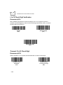
Transmit UPC-A Check Digit . . . . . . . . . . . . . . . . . . . . . . . . . . . . . . . . . . . . . . . . . . . . . . . .
Transmit UPC-E Check Digit . . . . . . . . . . . . . . . . . . . . . . . . . . . . . . . . . . . . . . . . . . . . . . . .
Transmit UPC-E1 Check Digit . . . . . . . . . . . . . . . . . . . . . . . . . . . . . . . . . . . . . . . . . . . . . . .
Convert UPC-E to UPC-A. . . . . . . . . . . . . . . . . . . . . . . . . . . . . . . . . . . . . . . . . . . . . . . . . . .
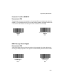
Convert UPC-E1 to UPC-A. . . . . . . . . . . . . . . . . . . . . . . . . . . . . . . . . . . . . . . . . . . . . . . . . .
Decode UPC/EAN Supplementals . . . . . . . . . . . . . . . . . . . . . . . . . . . . . . . . . . . . . . . . . . . .
Decode UPC/EAN Supplemental Redundancy . . . . . . . . . . . . . . . . . . . . . . . . . . . . . . . . . .
EAN-8 Zero Extend . . . . . . . . . . . . . . . . . . . . . . . . . . . . . . . . . . . . . . . . . . . . . . . . . . . . . . .
Convert EAN-8 to EAN-13 Type. . . . . . . . . . . . . . . . . . . . . . . . . . . . . . . . . . . . . . . . . . . . . .
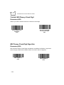
UPC/EAN Coupon Code . . . . . . . . . . . . . . . . . . . . . . . . . . . . . . . . . . . . . . . . . . . . . . . . . . .
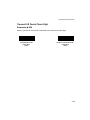
UPC-A/UPC-E Preamble . . . . . . . . . . . . . . . . . . . . . . . . . . . . . . . . . . . . . . . . . . . . . . . . . . .
Code 39 Check Digit Verification . . . . . . . . . . . . . . . . . . . . . . . . . . . . . . . . . . . . . . . . . . . . .
Transmit Code 39 Check Digit . . . . . . . . . . . . . . . . . . . . . . . . . . . . . . . . . . . . . . . . . . . . . . .
Convert Code 39 to Code 32 . . . . . . . . . . . . . . . . . . . . . . . . . . . . . . . . . . . . . . . . . . . . . . . .
Code 32 Prefix . . . . . . . . . . . . . . . . . . . . . . . . . . . . . . . . . . . . . . . . . . . . . . . . . . . . . . . . . . .
I 2 of 5 Check Digit Verification. . . . . . . . . . . . . . . . . . . . . . . . . . . . . . . . . . . . . . . . . . . . . . .
2-37
2-37
2-37
2-38
2-38
2-38
2-39
2-39
2-39
2-39
2-40
2-40
2-40
2-41
2-41
2-41
2-41
2-42
2-42
2-42
2-43
2-44
2-45
2-46
2-47
2-48
2-49
2-50
2-50
2-50
2-51
2-51
2-52
2-53
2-54
2-54
2-55
2-55
2-56
2-58
2-58
2-59
2-59
2-60
v
VS 4000 Series Product Reference Guide
Transmit I 2 of 5 Check Digit . . . . . . . . . . . . . . . . . . . . . . . . . . . . . . . . . . . . . . . . . . . . . . . . . 2-60
Convert I 2 of 5 to EAN-13. . . . . . . . . . . . . . . . . . . . . . . . . . . . . . . . . . . . . . . . . . . . . . . . . . . 2-61
MSI Plessey Check Digits . . . . . . . . . . . . . . . . . . . . . . . . . . . . . . . . . . . . . . . . . . . . . . . . . . . 2-61
Transmit MSI Plessey Check Digit. . . . . . . . . . . . . . . . . . . . . . . . . . . . . . . . . . . . . . . . . . . . . 2-62
MSI Plessey Check Digit Algorithm . . . . . . . . . . . . . . . . . . . . . . . . . . . . . . . . . . . . . . . . . . . . 2-62
Transmit US Postal Check Digit. . . . . . . . . . . . . . . . . . . . . . . . . . . . . . . . . . . . . . . . . . . . . . . 2-63
CLSI Editing . . . . . . . . . . . . . . . . . . . . . . . . . . . . . . . . . . . . . . . . . . . . . . . . . . . . . . . . . . . . . . 2-64
NOTIS Editing . . . . . . . . . . . . . . . . . . . . . . . . . . . . . . . . . . . . . . . . . . . . . . . . . . . . . . . . . . . . 2-64
Code 128 Emulation . . . . . . . . . . . . . . . . . . . . . . . . . . . . . . . . . . . . . . . . . . . . . . . . . . . . . . . 2-65
Transmit Code ID Character . . . . . . . . . . . . . . . . . . . . . . . . . . . . . . . . . . . . . . . . . . . . . . . . . 2-66
Transmit “No Decode” Message . . . . . . . . . . . . . . . . . . . . . . . . . . . . . . . . . . . . . . . . . . . . . . 2-68
LRC Checksum . . . . . . . . . . . . . . . . . . . . . . . . . . . . . . . . . . . . . . . . . . . . . . . . . . . . . . . . . . . 2-68
Prefix/Suffix Values . . . . . . . . . . . . . . . . . . . . . . . . . . . . . . . . . . . . . . . . . . . . . . . . . . . . . . . . 2-69
Data Transmission Formats. . . . . . . . . . . . . . . . . . . . . . . . . . . . . . . . . . . . . . . . . . . . . . . . . . 2-70
Security Options . . . . . . . . . . . . . . . . . . . . . . . . . . . . . . . . . . . . . . . . . . . . . . . . . . . . . . . . . . . . . . 2-72
Linear Code Type Security Level. . . . . . . . . . . . . . . . . . . . . . . . . . . . . . . . . . . . . . . . . . . . . . 2-72
UPC/EAN Security Level . . . . . . . . . . . . . . . . . . . . . . . . . . . . . . . . . . . . . . . . . . . . . . . . . . . . 2-74
Host Communication Options . . . . . . . . . . . . . . . . . . . . . . . . . . . . . . . . . . . . . . . . . . . . . . . . . . . . 2-76
Baud Rate . . . . . . . . . . . . . . . . . . . . . . . . . . . . . . . . . . . . . . . . . . . . . . . . . . . . . . . . . . . . . . . 2-76
Parity . . . . . . . . . . . . . . . . . . . . . . . . . . . . . . . . . . . . . . . . . . . . . . . . . . . . . . . . . . . . . . . . . . . 2-78
Check Parity . . . . . . . . . . . . . . . . . . . . . . . . . . . . . . . . . . . . . . . . . . . . . . . . . . . . . . . . . . . . . 2-78
Stop Bit Select . . . . . . . . . . . . . . . . . . . . . . . . . . . . . . . . . . . . . . . . . . . . . . . . . . . . . . . . . . . . 2-79
Hardware Handshaking . . . . . . . . . . . . . . . . . . . . . . . . . . . . . . . . . . . . . . . . . . . . . . . . . . . . . 2-79
Software Handshaking. . . . . . . . . . . . . . . . . . . . . . . . . . . . . . . . . . . . . . . . . . . . . . . . . . . . . . 2-82
Decode Data Packet Format . . . . . . . . . . . . . . . . . . . . . . . . . . . . . . . . . . . . . . . . . . . . . . . . . 2-84
Intercharacter Delay. . . . . . . . . . . . . . . . . . . . . . . . . . . . . . . . . . . . . . . . . . . . . . . . . . . . . . . . 2-85
Host Serial RTS Line State . . . . . . . . . . . . . . . . . . . . . . . . . . . . . . . . . . . . . . . . . . . . . . . . . . 2-86
Serial Response Timeout. . . . . . . . . . . . . . . . . . . . . . . . . . . . . . . . . . . . . . . . . . . . . . . . . . . . 2-87
Beep On <BEL>. . . . . . . . . . . . . . . . . . . . . . . . . . . . . . . . . . . . . . . . . . . . . . . . . . . . . . . . . . . 2-88
Data Transmission - 7 or 8-Bit ASCII Data Format . . . . . . . . . . . . . . . . . . . . . . . . . . . . . . . . 2-88
Report Version . . . . . . . . . . . . . . . . . . . . . . . . . . . . . . . . . . . . . . . . . . . . . . . . . . . . . . . . . . . . 2-89
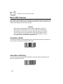
Macro PDF Features. . . . . . . . . . . . . . . . . . . . . . . . . . . . . . . . . . . . . . . . . . . . . . . . . . . . . . . . . . . 2-90
Flush Macro Buffer. . . . . . . . . . . . . . . . . . . . . . . . . . . . . . . . . . . . . . . . . . . . . . . . . . . . . . . . . 2-90
Abort Macro PDF Entry . . . . . . . . . . . . . . . . . . . . . . . . . . . . . . . . . . . . . . . . . . . . . . . . . . . . . 2-90
Numeric Bar Codes. . . . . . . . . . . . . . . . . . . . . . . . . . . . . . . . . . . . . . . . . . . . . . . . . . . . . . . . . . . . 2-91
Chapter 3. Advanced Data Formatting (ADF)
Introduction . . . . . . . . . . . . . . . . . . . . . . . . . . . . . . . . . . . . . . . . . . . . . . . . . . . . . . . . . . . . . . . . . . . 3-1
Rules: Criteria Linked to Actions. . . . . . . . . . . . . . . . . . . . . . . . . . . . . . . . . . . . . . . . . . . . . . . . . . . 3-1
Using ADF Bar Codes. . . . . . . . . . . . . . . . . . . . . . . . . . . . . . . . . . . . . . . . . . . . . . . . . . . . . . . . . . . 3-2
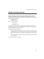
ADF Bar Code Menu Example . . . . . . . . . . . . . . . . . . . . . . . . . . . . . . . . . . . . . . . . . . . . . . . . . . . . 3-3
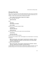
Alternate Rule Sets . . . . . . . . . . . . . . . . . . . . . . . . . . . . . . . . . . . . . . . . . . . . . . . . . . . . . . . . . 3-5
Rules Hierarchy (in Bar Codes) . . . . . . . . . . . . . . . . . . . . . . . . . . . . . . . . . . . . . . . . . . . . . . . . 3-6
vi
Contents
Default Rules . . . . . . . . . . . . . . . . . . . . . . . . . . . . . . . . . . . . . . . . . . . . . . . . . . . . . . . . . . . . . 3-7
Beeper Definitions for ADF . . . . . . . . . . . . . . . . . . . . . . . . . . . . . . . . . . . . . . . . . . . . . . . . . . . . . . 3-8
ADF Bar Codes . . . . . . . . . . . . . . . . . . . . . . . . . . . . . . . . . . . . . . . . . . . . . . . . . . . . . . . . . . . . . . . 3-9
Special Commands . . . . . . . . . . . . . . . . . . . . . . . . . . . . . . . . . . . . . . . . . . . . . . . . . . . . . . . . . . . 3-11
Begin New Rule . . . . . . . . . . . . . . . . . . . . . . . . . . . . . . . . . . . . . . . . . . . . . . . . . . . . . . . . . . 3-11
Save Rule . . . . . . . . . . . . . . . . . . . . . . . . . . . . . . . . . . . . . . . . . . . . . . . . . . . . . . . . . . . . . . . 3-11
Erase . . . . . . . . . . . . . . . . . . . . . . . . . . . . . . . . . . . . . . . . . . . . . . . . . . . . . . . . . . . . . . . . . . 3-12
Quit Entering Rules . . . . . . . . . . . . . . . . . . . . . . . . . . . . . . . . . . . . . . . . . . . . . . . . . . . . . . . 3-12
Disable Rule Set. . . . . . . . . . . . . . . . . . . . . . . . . . . . . . . . . . . . . . . . . . . . . . . . . . . . . . . . . . 3-13
Criteria . . . . . . . . . . . . . . . . . . . . . . . . . . . . . . . . . . . . . . . . . . . . . . . . . . . . . . . . . . . . . . . . . . . . . 3-14
Code Types . . . . . . . . . . . . . . . . . . . . . . . . . . . . . . . . . . . . . . . . . . . . . . . . . . . . . . . . . . . . . 3-14
Code Lengths . . . . . . . . . . . . . . . . . . . . . . . . . . . . . . . . . . . . . . . . . . . . . . . . . . . . . . . . . . . . 3-18
Message Containing A Specific Data String . . . . . . . . . . . . . . . . . . . . . . . . . . . . . . . . . . . . . 3-24
Numeric Keypad . . . . . . . . . . . . . . . . . . . . . . . . . . . . . . . . . . . . . . . . . . . . . . . . . . . . . . . . . . 3-25
Rule Belongs To Set. . . . . . . . . . . . . . . . . . . . . . . . . . . . . . . . . . . . . . . . . . . . . . . . . . . . . . . 3-27
Actions . . . . . . . . . . . . . . . . . . . . . . . . . . . . . . . . . . . . . . . . . . . . . . . . . . . . . . . . . . . . . . . . . . . . . 3-28
Send Data. . . . . . . . . . . . . . . . . . . . . . . . . . . . . . . . . . . . . . . . . . . . . . . . . . . . . . . . . . . . . . . 3-28
Pause Duration . . . . . . . . . . . . . . . . . . . . . . . . . . . . . . . . . . . . . . . . . . . . . . . . . . . . . . . . . . . 3-32
Setup Field(s) . . . . . . . . . . . . . . . . . . . . . . . . . . . . . . . . . . . . . . . . . . . . . . . . . . . . . . . . . . . . 3-32
Set Preset Value. . . . . . . . . . . . . . . . . . . . . . . . . . . . . . . . . . . . . . . . . . . . . . . . . . . . . . . . . . 3-40
Send Preset Value . . . . . . . . . . . . . . . . . . . . . . . . . . . . . . . . . . . . . . . . . . . . . . . . . . . . . . . . 3-41
Modify Data . . . . . . . . . . . . . . . . . . . . . . . . . . . . . . . . . . . . . . . . . . . . . . . . . . . . . . . . . . . . . 3-42
Beeps . . . . . . . . . . . . . . . . . . . . . . . . . . . . . . . . . . . . . . . . . . . . . . . . . . . . . . . . . . . . . . . . . . 3-54
Send Keystroke (Control Characters and Keyboard Characters) . . . . . . . . . . . . . . . . . . . . . 3-55
Turn On/Off Rule Sets . . . . . . . . . . . . . . . . . . . . . . . . . . . . . . . . . . . . . . . . . . . . . . . . . . . . . 3-90
Alphanumeric Keyboard. . . . . . . . . . . . . . . . . . . . . . . . . . . . . . . . . . . . . . . . . . . . . . . . . . . . . . . . 3-91
Chapter 4. Maintenance and Troubleshooting
Maintenance . . . . . . . . . . . . . . . . . . . . . . . . . . . . . . . . . . . . . . . . . . . . . . . . . . . . . . . . . . . . . . . . . 4-1
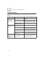
Troubleshooting . . . . . . . . . . . . . . . . . . . . . . . . . . . . . . . . . . . . . . . . . . . . . . . . . . . . . . . . . . . . . . . 4-2
Appendix A. Programming Reference
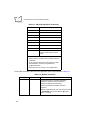
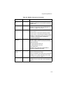
AIM Code Identifiers . . . . . . . . . . . . . . . . . . . . . . . . . . . . . . . . . . . . . . . . . . . . . . . . . . . . . . . . . . .
Enable AIM ID Characters . . . . . . . . . . . . . . . . . . . . . . . . . . . . . . . . . . . . . . . . . . . . . . . . . . .
Prefix / Suffix Values . . . . . . . . . . . . . . . . . . . . . . . . . . . . . . . . . . . . . . . . . . . . . . . . . . . . . . . . . . .
Host Qualification of Trigger, RS-232 Host Mode . . . . . . . . . . . . . . . . . . . . . . . . . . . . . . . . . . . . .
A-1
A-5
A-7
A-9
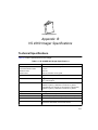
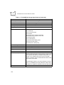
Appendix B. VS 4000 Imager Specifications
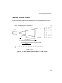
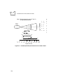
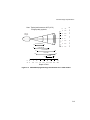
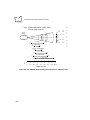
Technical Specifications. . . . . . . . . . . . . . . . . . . . . . . . . . . . . . . . . . . . . . . . . . . . . . . . . . . . . . . . . B-1
VS 4000 Decode Zones. . . . . . . . . . . . . . . . . . . . . . . . . . . . . . . . . . . . . . . . . . . . . . . . . . . . . . . . . B-3
Cable Pinouts . . . . . . . . . . . . . . . . . . . . . . . . . . . . . . . . . . . . . . . . . . . . . . . . . . . . . . . . . . . . . . . . B-7
vii
VS 4000 Series Product Reference Guide
Glossary
Index
Feedback
viii
About This Guide
Introduction
This manual provides general instructions for setting up, operating, troubleshooting,
maintaining, and programming your VS 4000 Series Imager. The target audience is a
system administrator or other personnel responsible for getting the imager up and running
in its intended environment.
Chapter Descriptions
The manual includes the following chapters.
•
Chapter 1, Getting Started, provides a product overview and information on
connecting the imager to the host. It also provides scanning instructions and
beeper definitions.
•
Chapter 2, Programming the VS 4000, provides all the bar codes necessary to
program your imager.
•
Chapter 3, Advanced Data Formatting (ADF), describes how to customize scanned
data in your imager before transmitting it to the host.
•
Chapter 4, Maintenance and Troubleshooting , includes tips on maintaining and
troubleshooting your imager.
•
Appendix A, Programming Reference, provides information on AIM identifiers and
prefix/suffix values.
•
Appendix B, VS 4000 Imager Specifications, lists the imager’s technical
specifications and provides decode ranges.
ix
VS 4000 Series Product Reference Guide
Notational Conventions
The following conventions are used in this document:
•
“You” refers to the administrator who is using this manual as a reference aid to
install, configure, operate, maintain, and troubleshoot the VS 4000 Series Imager.
•
Bold type is used to highlight specific items in the general text.
•
Italics are used to identify chapters and sections in this and related documents.
•
Bullets (♦) indicate:
•
•
action items
•
lists of alternatives
•
lists of required steps that are not necessarily sequential
Sequential lists (e.g., those that describe step-by-step procedures) appear as
numbered lists.
Related Publications
•
VS 4000 Series Quick Reference Guide
p/n 72-38485-xx
This document provides general information to help the user get started with the
imager, and includes basic operation instructions.
Service Information
If you have a problem with your equipment, contact the Symbol Support Center for your
region. Refer to page xi for information. Before calling, have the model number, serial
number, and several of your bar code symbols at hand.
Call the Support Center from a phone near the scanning equipment so that the service
person can try to talk you through the problem. In order to help troubleshoot a scanning
problem, the Support Center may request to capture a picture of test patterns or bar codes
with your imager and E-Mail to our plant for analysis. If the equipment is found to be working
properly and the problem is symbol readability, the Support Center may also request
samples of your bar codes for further analysis.
If your problem cannot be solved over the phone, you may need to return your equipment
for servicing. If that is necessary, you will be given specific directions.
x
About This Guide
Note:Symbol Technologies is not responsible for any damages incurred
during shipment if the approved shipping container is not used.
Shipping the units improperly can possibly void the warranty. If the
original shipping container was not kept, contact Symbol to have
another sent to you.
Symbol Support Centers
For service information, warranty information or technical assistance contact or call the
Symbol Support Center in:
United States
Symbol Technologies, Inc.
One Symbol Plaza
Holtsville, New York 11742-1300
1-800-653-5350
Canada
Symbol Technologies Canada, Inc.
2540 Matheson Boulevard East
Mississauga, Ontario, Canada L4W 4Z2
905-629-7226
United Kingdom
Symbol Technologies
Symbol Place
Winnersh Triangle, Berkshire RG41 5TP
United Kingdom
0800 328 2424 (Inside UK)
+44 208 945 7529 (Outside UK)
Asia/Pacific
Symbol Technologies Asia, Inc.
230 Victoria Street #04-05
Bugis Junction Office Tower
Singapore 188024
337-6588 (Inside Singapore)
+65-337-6588 (Outside Singapore)
Australia
Symbol Technologies Pty. Ltd.
432 St. Kilda Road
Melbourne, Victoria 3004
1-800-672-906 (Inside Australia)
+61-3-9866-6044 (Outside Australia)
Austria
Symbol Technologies Austria GmbH
Prinz-Eugen Strasse 70
Suite 3
2.Haus, 5.Stock
1040 Vienna, Austria
1-505-5794 (Inside Austria)
+43-1-505-5794 (Outside Austria)
xi
VS 4000 Series Product Reference Guide
Denmark
Symbol Technologies AS
Gydevang 2,
DK-3450 Allerod, Denmark
7020-1718 (Inside Denmark)
+45-7020-1718 (Outside Denmark)
Finland
Oy Symbol Technologies
Kaupintie 8 A 6
FIN-00440 Helsinki, Finland
9 5407 580 (Inside Finland)
+358 9 5407 580 (Outside Finland)
Germany
Symbol Technologies GmbH
Waldstrasse 68
D-63128 Dietzenbach, Germany
6074-49020 (Inside Germany)
+49-6074-49020 (Outside Germany)
Europe/Mid-East Distributor Operations
Contact your local distributor or call
+44 118 945 7360
France
Symbol Technologies France
Centre d'Affaire d'Antony
3 Rue de la Renaissance
92184 Antony Cedex, France
01-40-96-52-21 (Inside France)
+33-1-40-96-52-50 (Outside France)
Italy
Symbol Technologies Italia S.R.L.
Via Cristoforo Columbo, 49
20090 Trezzano S/N Navigilo
Milano, Italy
2-484441 (Inside Italy)
+39-02-484441 (Outside Italy)
Latin America Sales Support
7900 Glades Road
Suite 340
Boca Raton, Florida 33434 USA
1-800-347-0178 (Inside United States)
+1-561-483-1275 (Outside United States)
Mexico
Symbol Technologies Mexico Ltd.
Torre Picasso
Boulevard Manuel Avila Camacho No 88
Lomas de Chapultepec CP 11000
Mexico City, DF, Mexico
5-520-1835 (Inside Mexico)
+52-5-520-1835 (Outside Mexico)
Netherlands
Symbol Technologies
Kerkplein 2, 7051 CX
Postbus 24 7050 AA
Varsseveld, Netherlands
315-271700 (Inside Netherlands)
+31-315-271700 (Outside Netherlands)
Norway
Symbol Technologies
Trollasveien 36
Postboks 72
1414 Trollasen, Norway
66810600 (Inside Norway)
+47-66810600 (Outside Norway)
xii
About This Guide
South Africa
Symbol Technologies Africa Inc.
Block B2
Rutherford Estate
1 Scott Street
Waverly 2090 Johannesburg
Republic of South Africa
11-4405668 (Inside South Africa)
+27-11-4405668 (Outside South Africa)
Spain
Symbol Technologies S.A.
Edificioi la Piovera Azul
C. Peonias, No. 2 - Sexta Planta
28042 Madrid, Spain
9-1-320-39-09 (Inside Spain)
+34-9-1-320-39-09 (Outside Spain)
Sweden
Symbol Technologies AB
Albygatan 109D
Solna
Sweden
84452900 (Inside Sweden)
+46 84452900 (Outside Sweden)
If you purchased your Symbol product from a Symbol Business Partner, contact that
Business Partner for service.
Warranty
Symbol Technologies, Inc. (“Symbol”) manufactures its hardware products in accordance with
industry-standard practices. Symbol warrants that for a period of twelve (12) months from date of
shipment, products will be free from defects in materials and workmanship.
This warranty is provided to the original owner only and is not transferable to any third party. It shall
not apply to any product (i) which has been repaired or altered unless done or approved by Symbol,
(ii) which has not been maintained in accordance with any operating or handling instructions supplied
by Symbol, (iii) which has been subjected to unusual physical or electrical stress, misuse, abuse,
power shortage, negligence or accident or (iv) which has been used other than in accordance with
the product operating and handling instructions. Preventive maintenance is the responsibility of
customer and is not covered under this warranty.
Wear items and accessories having a Symbol serial number, will carry a 90-day limited warranty. Nonserialized items will carry a 30-day limited warranty.
xiii
VS 4000 Series Product Reference Guide
Warranty Coverage and Procedure
During the warranty period, Symbol will repair or replace defective products returned to Symbol’s
manufacturing plant in the US. For warranty service in North America, call the Symbol Support Center
at 1-800-653-5350. International customers should contact the local Symbol office or support center.
If warranty service is required, Symbol will issue a Return Material Authorization Number. Products
must be shipped in the original or comparable packaging, shipping and insurance charges prepaid.
Symbol will ship the repaired or replacement product freight and insurance prepaid in North America.
Shipments from the US or other locations will be made F.O.B. Symbol’s manufacturing plant.
Symbol will use new or refurbished parts at its discretion and will own all parts removed from repaired
products. Customer will pay for the replacement product in case it does not return the replaced
product to Symbol within 3 days of receipt of the replacement product. The process for return and
customer’s charges will be in accordance with Symbol’s Exchange Policy in effect at the time of the
exchange.
Customer accepts full responsibility for its software and data including the appropriate backup
thereof.
Repair or replacement of a product during warranty will not extend the original warranty term.
Symbol’s Customer Service organization offers an array of service plans, such as on-site, depot, or
phone support, that can be implemented to meet customer’s special operational requirements and
are available at a substantial discount during warranty period.
General
Except for the warranties stated above, Symbol disclaims all warranties, express or implied, on
products furnished hereunder, including without limitation implied warranties of merchantability and
fitness for a particular purpose. The stated express warranties are in lieu of all obligations or liabilities
on part of Symbol for damages, including without limitation, special, indirect, or consequential
damages arising out of or in connection with the use or performance of the product.
Seller’s liability for damages to buyer or others resulting from the use of any product, shall in no way
exceed the purchase price of said product, except in instances of injury to persons or property.
Some states (or jurisdictions) do not allow the exclusion or limitation of incidental or consequential
damages, so the proceeding exclusion or limitation may not apply to you.
xiv
Chapter 1
Getting Started
Introduction
The VS 4000 Series hand-held imager is a high-performance, durable solution for a wide
variety of data collection applications using the latest digital camera technology. This
system features:
•
omnidirectional reading of a variety of bar code symbologies, including the most
popular linear, postal, PDF417, and 2D matrix code types.
•
the ability to capture and download images to a host for a variety of imaging
applications.
•
advanced intuitive laser aiming for easy point-and-shoot operation.
•
a tough, ergonomic thermoplastic housing for comfort and durability.
The VS 4000 supports the following interfaces:
•
Standard RS-232 interface for serial connection to a host. The imager
communicates with the host through scanned bar codes.
•
Keyboard wedge via Symbol’s Synapse cables, where scanned data is interpreted
by the host as keystrokes.
This chapter describes how to set up the imager with your host system, how to operate the
imager, and defines beeper indications.
1-1
VS 4000 Series Product Reference Guide
Unpacking
Remove the imager from its packing and inspect it for damage. If the scanner was damaged
in transit, call the Symbol Support Center at one of the telephone numbers listed on page
xi. KEEP THE PACKING. It is the approved shipping container and should be used if you
ever need to return your equipment for servicing.
Setting Up the Imager
This section provides instructions first on connecting the interface cable to the imager, then
to each supported interface.
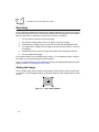
Connecting the Interface Cable to the VS 4000
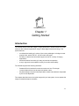
To attach the supplied interface cable to your imager:
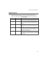
1. Pull the boot up over the cable until just the connector is protruding.
Figure 1-1. Connector on Cable
1-2
Getting Started
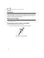
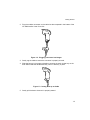
2. Plug the modular connector on the cable into the receptacle in the bottom of the
VS 4000 handle. Listen for a click.
Figure 1-2. Plugging Connector into Imager
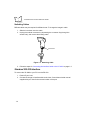
3. Gently tug the cable to ensure the connector is properly secured.
4. Slide the boot up in its proper orientation, ensuring the semi-circular key on the
boot slides inside the handle assembly, until it is securely in place.
Figure 1-3. Sliding Boot up on Cable
5. Gently pull the boot to be sure it is properly seated.
1-3
VS 4000 Series Product Reference Guide
Switching Cables
Different cables may be required for different hosts. To change the imager’s cable:
1. Slide the boot down over the cable.
2. Unplug the modular connector by depressing the connector clip (through the
access hole), and remove the existing cable.
Access Hole
Figure 1-4. Removing Cable
3. Follow the steps for Connecting the Interface Cable to the VS 4000 on page 1-2.
Standard RS-232 Interface
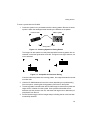
To connect the VS 4000 to your PC host via RS-232:
1. Power off your host.
2. Connect the imager’s interface cable to the host. Consult the technical manual
supplied with your host for the correct location of the port.
1-4
Getting Started
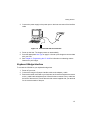
3. Connect the power supply to the power port on the host connector of the interface
cable.
Figure 1-5. Standard RS-232 Host Interface
4. Power up the host. The imager powers on automatically.
5. Scan the appropriate Host Type on page 2-13 to set up the imager to communicate
with your host.
6. See Chapter 2, Programming the VS 4000 for information on selecting custom
features for your imager.
Keyboard Wedge Interface
To connect the VS 4000 to your keyboard wedge host:
1. Power off your host.
2. Connect the imager’s Synapse interface cable to the adapter y-cable.
3. Remove the cable connected to your keyboard, and insert the keyboard connector
on the y-cable into that keyboard port. Insert the other connector of the y-cable into
the back of the terminal. Consult the technical manual supplied with your terminal
for the correct location of the port.
1-5
VS 4000 Series Product Reference Guide
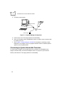
4. Connect a power supply.
Synapse Smart
Synapse Adapter
Cable
Power Supply
Figure 1-6. Keyboard Wedge Configuration
5. Power up the host. The imager powers on automatically.
6. Since your Synapse host is autodetected, there’s no need to scan a host bar code
to choose your host.
7. See Chapter 2, Programming the VS 4000 for information on selecting custom
features for your imager, and your Synapse Interface Guide for interface options
specific to your Synapse cable.
Connecting to Symbol Hand-Held Terminals
To connect the VS 4000 to your Symbol terminal, connect the mini-D adapter to the
imager’s interface cable, and insert the adapter into the 15-pin port on your terminal.
Power up the terminal. The imager powers on automatically.
1-6
Getting Started
Accessories
Depending on your host system’s configuration, the following items may be included in your
imager system. These items are also available through contacting your local Symbol
representative or business partner.
Standard Accessories
These items may be included in your system.
•
9-Pin Host interface cable, Female, D Connector/PC AT: TxD on Pin 2
•
100-240VAC (50/60Hz) Universal Power Supply
•
User Documentation
•
VS 4000 Series Product Reference Guide
•
VS 4000 Series Quick Reference Guide
Optional Accessories
Optional accessories are not included in the standard configuration, and are available
through contacting your local Symbol representative or business partner.
•
15-Pin host interface cable, Male, Mini-D Connector/PC AT: TxD on Pin 2
•
Synapse keyboard wedge interface and adapter cables
•
Desk stand
•
Hands-free stand
1-7
VS 4000 Series Product Reference Guide
Scanning
The VS 4000 uses digital camera technology to take a digital picture of a bar code. It stores
the resulting image in its memory, and executes software decoding algorithms to extract the
data from the image. A typical bar code decoding process is as follows:
1. The user aims the imager and pulls the trigger.
2. The red laser aiming pattern turns on to assist in aiming the imager.
3. If necessary, the imager turns on its red LEDs to illuminate the target bar code.
4. The imager takes a digital picture (image) of the bar code and stores it in memory
for decoding.
5. A decode beep occurs and the imager transmits the bar code data to the host.
6. The user releases the trigger.
This process usually occurs instantaneously. Steps 2 - 4 are repeated on poor or difficult
bar codes, for as long as the trigger remains pressed.
You may customize features in the VS 4000 by scanning the appropriate programming bar
codes in Chapter 2, Programming the VS 4000.
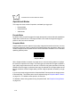
Aiming the Imager
The VS 4000 Imager projects a laser aiming pattern (shown below) similar to those used
on cameras. The aiming pattern allows you to position the bar code or object within the field
of view.
Figure 1-7. Laser Aiming Pattern
1-8
Getting Started
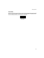
To scan a symbol with the VS 4000:
1. Center the symbol in any orientation within the aiming pattern. Be sure the entire
symbol is within the rectangular area formed by the brackets in the pattern.
Linear bar code
PDF417 symbol
Symbol
Aiming Pattern
Figure 1-8. Centering Symbol in Aiming Pattern
The imager can also read a bar code presented within the aiming pattern but not
centered, such as the figure below on the left. The figure on the right, however, can
not be decoded.
Figure 1-9. Acceptable and Incorrect Aiming
If two bar codes are present in the aiming pattern, the imager decodes the centralmost bar code.
2. Hold the VS 4000 between two and nine inches (depending on symbol density)
from the symbol, centering the aiming pattern cross hairs on the symbol.
3. The aiming pattern is smaller when the VS 4000 Imager is closer to the symbol and
larger when it is farther from the symbol. Scan symbols with smaller bars or
elements (mil size) closer to the unit, and those with larger bars or elements (mil
size) farther from the unit.
4. Pull and hold the trigger until the imager beeps, indicating the bar code has been
successfully decoded.
1-9
VS 4000 Series Product Reference Guide
Operational Modes
The imager has three modes of operation, activated by a trigger pull:
•
Decode Mode
•
Snapshot Mode
•
Video Mode.
Decode Mode
By default, when you pull the trigger the imager attempts to locate and decode enabled bar
codes within its field of view. The imager remains in this mode as long as the trigger is
pulled or until a bar code is decoded.
Snapshot Mode
Snapshot Mode is used to capture a high-quality image and transmit it to the host. You may
temporarily enter this mode by scanning the Snapshot Mode bar code below. While in this
mode the imager blinks the yellow LED at 1-second intervals to indicate it is not in standard
operating (decode) mode.
Snapshot Mode
When Snapshot Mode is entered, the imager turns on its laser aiming pattern to highlight
the area to be captured in the image. The next trigger pull instructs the imager to capture a
high quality image and transmit it to the host. A short time may pass (less than 2 seconds)
between when the trigger is pulled and the image is captured as the imager adjusts to the
lighting conditions. Hold the imager steady until the image is captured, denoted by a single
beep.
If you do not press the trigger within the Snapshot Mode Timeout period, the imager returns
to Decode Mode. This timeout period can be adjusted using the Snapshot Mode Timeout
on page 2-23. The default timeout period is 30 seconds.
To disable the laser aiming pattern during Snapshot Mode, see Snapshot Aiming Pattern
on page 2-24.
1-10
Getting Started
Video Mode
While in this mode the imager behaves as a video camera as long as the trigger is pressed.
When the trigger is released, the imager returns to Decode Mode. You may temporarily
enter Video Capture Mode by scanning the bar code below.
Video Mode
1-11
VS 4000 Series Product Reference Guide
Beeper Definitions
The imager communicates with the user by emitting different beep tones and patterns. The
following tables define what each beep sequence means.
Standard Beeper Definitions
Table 1-1 defines general beep sequences that occur during both normal scanning and
while programming the imager.
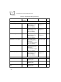
Table 1-1. Standard Beeper Definitions
Beeper Sequence
Indication
Standard Use
Short high tone
A bar code symbol was decoded (if decode beeper is enabled).
Low/medium/high tone
Power-on or reset. Occurs immediately after the unit is turned on,
indicating that the system software is working properly.
Three beeps which occur during normal operation indicate a
reset. Any work in progress may be lost. If this occurs often,
contact the Symbol Support Center.
Parameter Menu Scanning
Short high tone
Correct entry scanned or correct menu sequence performed.
High/low/high/low tone
Successful program exit with change in the parameter setting.
Low/high tone
Input error, incorrect bar code, or “Cancel” scanned, wrong entry,
incorrect bar code programming sequence; remain in program
mode.
Communication
4 short high tones
Communication error.
High/high/high/low tone
Receive error.
Low/high/low tone
ADF transmit error.
1-12
Getting Started
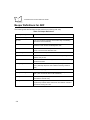
Special Beeper/Status LED Definitions
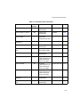
Table 1-2 define beeper and Status LED activity indicating special events.
Table 1-2. Special Beeper and Status LED Indications
Event
Beep Tone
Status LEDs
Decode
Middle
Green Flash
Trigger pull
No sound
No Lights
Bootup
Low, Middle, High
No Lights
Transmission error
Four Low
No Lights
Parity error
Three Low, Two Extra Low
No Lights
Start snapshot
Low
Blinking Yellow
Complete snapshot
Low
No Lights
Entry error
Low, High
Green Flash
Parameter entered
High, Low, High, Low
Green Flash
Defaults set
Low High, High
Green Flash
No Decode message
No sound
No Lights
Video Mode enabled
No sound
Yellow Light
Video Mode disabled
No sound
No Lights
Wakeup (from low power)
No sound
No Lights
CCD failure
Two Very Low Long
Blinking Red
Parameter scanned
Middle
Green Flash
Synapse - Invalid parameter
High, Low, High, Low
No Lights
Synapse failure
Very Low, Low, Very Low, High
Red Flash
ADF Beeper/Status LED Definitions
See Table 3-3 on page 3-8 for beeper and status LED events that occur during ADF
programming.
1-13
VS 4000 Series Product Reference Guide
1-14
Chapter 2
Programming the VS 4000
Introduction
The VS 4000 Imager can be programmed to perform various functions, or activate different
features. This chapter describes each feature and provides the programming bar codes
necessary for selecting these features for your imager. Before programming, follow the
setup instructions in Chapter 1, Getting Started.
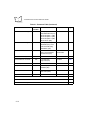
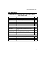
Table 2-1 on page 2-4 shows selectable programming options and their default values for
the VS 4000. Throughout the programming bar code menus, default values are indicated
with asterisks (*), and the hex value of the option is provided for serial programming
purposes.
Indicates Default
Feature
*Enable Feature
(01h)
Hex Value
2-1
VS 4000 Series Product Reference Guide
If the default values suit your requirements, no programming is necessary. Features other
than default values can be set by scanning single bar codes or short bar code sequences.
These features may also be set from the host through the serial interface. Note that these
settings are stored in non-volatile memory and are retained after powerdown.
To return all features (except Host Type) to their default values, all you need to do is scan
the Set Defaults bar code on page 2-3.
Scanning Sequence Examples
In most cases you need only scan one bar code to set a specific parameter. For example,
if you want to set the baud rate to 9600, simply scan the 9600 bar code listed under Baud
Rate on page 2-76. The imager issues a warble tone, signifying a successful parameter
entry.
If you want to set specific code lengths or specify Serial Response Time-Out, you have to
scan several bar codes. This procedure is described later in this chapter.
Errors While Scanning
If you make an error during a scanning sequence, just rescan the correct parameter.
2-2
Programming the VS 4000
Set Default Parameter
Scan the Set Defaults bar code to return all parameters to the default values listed in
Table 2-1.
Set Defaults
2-3
VS 4000 Series Product Reference Guide
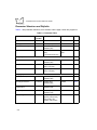
Parameter Selections and Defaults
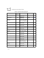
Table 2-1 lists parameter selections, their defaults, and the page number they appear on.
Table 2-1. Parameter Tabl e
Parameter
Param.
Number
Set Defaults
Selection
Default
Page
None
Set Default Values
2-3
Host Type
8Eh
RS-232 (37h)
RS-232
2-13
Parameter Scanning
ECh
Enabled (01h)
Disabled (00h)
Enabled
2-14
Power Mode
80h
Continuous On Mode
(00h)
Low Power Mode (01h)
Continuous On
Mode
2-14
Beeper Options
2-15
Beep After Good Decode
38h
Enabled (01h)
Disabled (00h)
Enabled
2-15
Beeper Volume
8Ch
High (09h), Medium
(03h), Low (00h)
Medium
2-16
Beeper Tone
91h
High (00h), Medium
(01h), Low (02h)
Medium
2-17
Imaging Options
2-18
Decoding Autoexposure
F0h,29h
Enabled (01h)
Disabled (00h)
Enabled
2-19
Decoding Illumination
F0h,2Ah
Enabled (01h)
Disabled (00h)
Enabled
2-19
Image Capture
Autoexposure
F0h,68h
Enabled (01h)
Disabled (00h)
Enabled
2-20
Image Capture Illumination
F0h,69h
Enabled (01h)
Disabled (00h)
Disabled
2-20
Gain Setting
F0h,37h
128 (0080h), 192
(00C0h), 256 (0100h),
320 (0140h), 384
(0180h), 448 (01C0h)
192
2-21
2-4
Programming the VS 4000
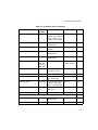
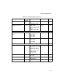
Table 2-1. Parameter Table (Continued)
Parameter
Param.
Number
Selection
Default
Page
Exposure Time
F0h,38h
20 ms
5 ms (004Fh), 10 ms
(009Dh), 15 ms (00ECh),
20 ms (013Bh), 25 ms
(018Ah), 30 ms (01D8h)
2-22
Decode Aiming Pattern
F0h,32h
Enabled (02h)
Disabled (00h)
Enabled
2-23
Snapshot Mode Timeout
F0h,43h
0 - 9 (30 seconds - 300
seconds)
0 (30 seconds)
2-23
Snapshot Aiming Pattern
F0h,2Ch
Enabled (01h)
Disabled (00h)
Enabled
2-24
Image Cropping
F0h,2Dh
Enabled (01h)
Disabled (00h)
Disabled
2-24
Crop to Pixel Addresses
F0h,3Bh;
F0h,3Ch;
F0h,3D;
F0h,3Eh
(0,0) to (639,479)
0 top, 0 left, 479
bottom, 639 right
2-25
Image Resolution
F0h,2Eh
Full (00h), 1/2 (01h),
1/3 (02h), 1/4 (03h)
Full
2-27
JPEG Image Options
F0h,2Bh
Quality (01h), Size (00h) Quality
2-28
JPEG Quality Value
F0h,31h
5 to 100
(5 to 100 decimal)
65
2-28
JPEG Size Value
F0h,33h
1 to 150 where value is
multiple of 1024 bytes
(1K) (1 to 150 decimal)
40 (41K)
2-28
Image File Format Selection
F0h,30h
BMP (03h), TIF (04h),
JPEG (01h)
JPEG
2-29
Bits per Pixel (BPP)
F0h,2Fh
1 (00h), 4 (01h), 8 (02h)
8 BPP
2-30
Video Options
2-31
Video View Finder
F0h,44h
Enabled (01h)
Disabled (00h)
Disabled
2-31
Target Video Frame Size
F0h,48h
800 to 3300 bytes
2200 bytes
2-32
2-5
VS 4000 Series Product Reference Guide
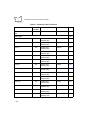
Table 2-1. Parameter Table (Continued)
Parameter
Video View Finder Image
Size
Param.
Number
Selection
F0h,49h
800 to 3300 bytes
Default
1700 bytes
Code Types
Page
2-32
2-33
UPC-A
01h
Enabled (01h)
Disabled (00h)
Enabled
2-34
UPC-E
02h
Enabled (01h)
Disabled (00h)
Enabled
2-34
UPC-E1
0Ch
Enabled (01h)
Disabled (00h)
Disabled
2-34
EAN-8
04h
Enabled (01h)
Disabled (00h)
Enabled
2-35
EAN-13
03h
Enabled (01h)
Disabled (00h)
Enabled
2-35
Bookland EAN
53h
Enabled (01h)
Disabled (00h)
Disabled
2-35
Code 39
00h
Enabled (01h)
Disabled (00h)
Enabled
2-36
Code 39 Full ASCII
11h
Enabled (01h)
Disabled (00h)
Disabled
2-36
Trioptic Code 39
0Dh
Enabled (01h)
Disabled (00h)
Disabled
2-36
Code 93
09h
Enabled (01h)
Disabled (00h)
Disabled
2-37
Code 128
08h
Enabled (01h)
Disabled (00h)
Enabled
2-37
UCC/EAN 128
0Eh
Enabled (01h)
Disabled (00h)
Enabled
2-37
ISBT 128
54h
Enabled (01h)
Disabled (00h)
Enabled
2-38
Codabar
07h
Enabled (01h)
Disabled (00h)
Disabled
2-38
2-6
Programming the VS 4000
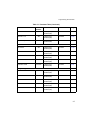
Table 2-1. Parameter Table (Continued)
Parameter
Param.
Number
Selection
Default
Page
Interleaved 2 of 5
06h
Enabled (01h)
Disabled (00h)
Disabled
2-38
Discrete 2 of 5
05h
Enabled (01h)
Disabled (00h)
Disabled
2-39
MSI Plessey
0Bh
Enabled (01h)
Disabled (00h)
Disabled
2-39
Postal Codes
2-39
US Postnet
59h
Enabled (01h)
Disabled (00h)
Enabled
2-39
US Planet
5Ah
Enabled (01h)
Disabled (00h)
Enabled
2-40
UK Postal
5Bh
Enabled (01h)
Disabled (00h)
Enabled
2-40
Japan Postal
F0h,22h
Enabled (01h)
Disabled (00h)
Enabled
2-40
Australian Postal
F0h,23h
Enabled (01h)
Disabled (00h)
Enabled
2-41
2D Symbologies
2-41
PDF417
0Fh
Enabled (01h)
Disabled (00h)
Enabled
2-41
MicroPDF417
E3h
Enabled (01h)
Disabled (00h)
Disabled
2-41
Data Matrix
F0h,24h
Enabled (01h)
Disabled (00h)
Enabled
2-42
Maxicode
F0h,26h
Enabled (01h)
Disabled (00h)
Enabled
2-42
QR Code
F0h,25h
Enabled (01h)
Disabled (00h)
Enabled
2-42
2-7
VS 4000 Series Product Reference Guide
Table 2-1. Parameter Table (Continued)
Parameter
Param.
Number
Selection
Default
Code Lengths
Page
2-43
Code 39 Lengths
12h, 13h
Any Length, Length
Within Range, 1 or 2
Discrete Lengths
(all 0 - 55 decimal)
Length Within
Range: 01-55
2-44
Code 93 Lengths
1Ah, 1Bh
Any Length, Length
Within Range, 1 or 2
Discrete Lengths
(all 0 - 55 decimal)
Length Within
Range: 04-55
2-45
Codabar Lengths
18h, 19h
Any Length, Length
Within Range, 1 or 2
Discrete Lengths
(all 0 - 55 decimal)
Length Within
Range: 05-55
2-46
Interleaved 2 of 5 Lengths
16h, 17h
Any Length, Length
Within Range (2 to 54
characters),
1 or 2 Discrete Lengths
(all 0 - 55 decimal)
1 Discrete Length
14
2-47
Discrete 2 of 5 Lengths
14h, 15h
Any Length, Length
Within Range (2 to 54
characters),
1 or 2 Discrete Lengths
(all 0 - 55 decimal)
1 Discrete Length
12
2-48
MSI Plessey Lengths
1Eh, 1Fh
Any Length, Length
Within Range, 1 or 2
Discrete Lengths
(all 0 - 55 decimal)
Length Within
Range: 01-55
2-49
Decode Options
2-50
Transmit UPC-A Check Digit
28h
Enabled (01h)
Disabled (00h)
Enabled
2-50
Transmit UPC-E Check Digit
29h
Enabled (01h)
Disabled (00h)
Enabled
2-50
Transmit UPC-E1 Check
Digit
2Ah
Enabled (01h)
Disabled (00h)
Enabled
2-50
2-8
Programming the VS 4000
Table 2-1. Parameter Table (Continued)
Parameter
Param.
Number
Selection
Default
Page
Convert UPC-E to UPC-A
25h
Enabled (01h)
Disabled (00h)
Disabled
2-51
Convert UPC-E1 to UPC-A
26h
Enabled (01h)
Disabled (00h)
Disabled
2-51
Decode UPC/EAN
Supplementals
10h
Decode (01h),
Ignore (00h),
Autodiscriminate (02h)
Ignore
2-53
UPC/EAN Supplemental
Redundancy
50h
2 - 20 times
20
2-54
EAN-8 Zero Extend
27h
Enabled (01h)
Disabled (00h)
Disabled
2-54
Convert EAN-8 to EAN-13
Type
E0h
Type is EAN-8 (01h)
Type is EAN-13 (00h)
Type is EAN-13
2-55
UPC/EAN Coupon Code
55h
Enabled (01h)
Disabled (00h)
Disabled
2-55
UPC-A Preamble
22h
None (00h)
System Character (01h)
System Character &
Country Code (02h)
System Character
2-56
UPC-E Preamble
23h
None (00h)
System Character (01h)
System Character &
Country Code (02h)
System Character
2-57
UPC-E1 Preamble
24h
None (00h)
System Character (01h)
System Character &
Country Code (02h)
System Character
2-57
Code 39 Check Digit
Verification
30h
Enabled (01h)
Disabled (00h)
Disabled
2-58
Transmit Code 39 Check
Digit
2Bh
Enabled (01h)
Disabled (00h)
Disabled
2-58
2-9
VS 4000 Series Product Reference Guide
Table 2-1. Parameter Table (Continued)
Parameter
Param.
Number
Convert Code 39 to Code 32
56h
Enabled (01h)
Disabled (00h)
Disabled
2-59
Code 32 Prefix
E7h
Enabled (01h)
Disabled (00h)
Enabled
2-59
I 2 of 5 Check Digit
Verification
31h
Disabled
Disabled (00h)
USS Check Digit (01h)
OPCC Check Digit (02h)
2-60
Transmit I 2 of 5 Check Digit
2Ch
Enabled (01h)
Disabled (00h)
Disabled
2-60
Convert I 2 of 5 to EAN-13
52h
Enabled (01h)
Disabled (00h)
Disabled
2-61
MSI Plessey Check Digits
32h
One (00h), Two (01h)
One
2-61
Transmit MSI Plessey Check
Digit
2Eh
Enabled (01h)
Disabled (00h)
Disabled
2-62
MSI Plessey Check Digit
Algorithm
33h
Mod 10/Mod 10 (01h)
Mod 11/Mod 10 (00h)
Mod 10/Mod 10
2-62
Transmit US Postal Check
Digit
5Fh
Enabled (01h)
Disabled (00h)
Enabled
2-63
CLSI Editing
36h
Enabled (01h)
Disabled (00h)
Disabled
2-64
NOTIS Editing
37h
Enabled (01h)
Disabled (00h)
Disabled
2-64
Code 128 Emulation
7Bh
Enabled (01h)
Disabled (00h)
Disabled
2-65
Transmit Code ID Character
2Dh
Disabled (00h)
AIM Standard (01h)
Symbol Standard (02h)
Disabled
2-66
Transmit “No Decode”
Message
5Eh
Enabled (01h)
Disabled (00h)
Disabled
2-68
Transmit LRC Checksum
7Eh
Enabled (01h)
Disabled (00h)
Disabled
2-68
2-10
Selection
Default
Page
Programming the VS 4000
Table 2-1. Parameter Table (Continued)
Parameter
Param.
Number
Prefix/Suffix Values
69h, 68h
Scan Data Transmission
Format
EBh
Selection
Default
Page
Prefix, Suffix
(4-Digit ASCII Value)
Enter
2-69
<Data> (00h)
<Data><Suffix> (01h)
<Prefix><Data><Suffix>
(05h)
<Prefix><Data> (04h)
<Data>
2-70
Security Options
2-72
Linear Code Type Security
Levels
4Eh
Level 1 (01h)
Level 2 (02h)
Level 3 (03h)
Level 4 (04h)
Level 2
2-72
UPC/EAN Security Levels
4Dh
Level 0 (00h)
Level 1 (01h)
Level 2 (02h)
Level 3 (03h)
0
2-74
Host Communication Options
2-76
Baud Rate
9Ch
9600
600 (2 dec), 1200 (3
dec), 2400 (4 dec), 4800
(5 dec), 9600 (6 dec),
19.2K (7 dec), 28.8 K
(9 dec), 38.4 K (8 dec),
57.6K (10 dec),
115.2K (11 dec)
2-76
Parity
9Eh
Even (01h), Odd (00h),
None (04h)
None
2-78
Check Parity
97h
Enabled (01h)
Disabled (00h)
Enabled
2-78
Stop Bit Select
9Dh
One (01h), Two (02h)
One
2-79
2-11
VS 4000 Series Product Reference Guide
Table 2-1. Parameter Table (Continued)
Parameter
Param.
Number
Selection
Default
Page
Hardware Handshaking
A0h
None
None (00h)
Standard RTS/CTS (01h)
RTS/CTS Option 1 (02h)
RTS/CTS Option 2 (03h)
RTS/CTS Option 3 (04h)
RTS/CTS PC (05h)
2-79
Software Handshaking
9Fh
None (00h), ENQ (03h),
ACK/NAK (01h), ACK/
NAK with ENQ (02h),
XON/XOFF (04h)
None
2-82
Decode Data Packet Format
EEh
Send Raw Decode Data
(00h), Send Packeted
Decode Data (01h)
Send Packeted
Decode Data
2-84
Intercharacter Delay
6Eh
00 - 99 ms.
0
2-85
Host Serial RTS Line State
9Ah
Low RTS (00h)
High RTS (01h)
Low RTS
2-86
Serial Response Time-out
9Bh
00 - 8.0 seconds
2.0 seconds
2-87
Beep on <BEL>
96h
Enabled (01h)
Disabled (00h)
Disabled
2-88
ASCII Format
A2h
7-Bit ASCII (07h)
8-Bit ASCII (08h)
8-Bit ASCII
2-88
Report Version
--
Software version
--
2-89
Macro PDF
2-90
Flush Macro Buffer
2-90
Abort Macro PDF Entry
2-90
2-12
Programming the VS 4000
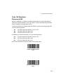
Host Type
Parameter # 8Eh
If you are using a Synapse cable, there’s no need to scan a host bar code, as the imager
autodetects your host.
*RS-232 Host
(37h)
2-13
VS 4000 Series Product Reference Guide
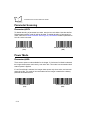
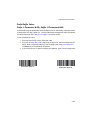
Parameter Scanning
Parameter # ECh
To disable decoding of parameter bar codes, scan the bar code below. Note that the Set
Defaults parameter bar code will still be decoded. To enable decoding of parameter bar
codes, either scan Enable Parameter Scanning (01h), Set Defaults or set this parameter to
01h via a serial command.
Enable Parameter Scanning
(01h)
Disable Parameter Scanning
(00h)
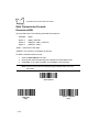
Power Mode
Parameter # 80h
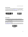
There are two power modes available for the imager. If Continuous On Mode is selected,
the imager draws power continuously, even when idle. This mode is recommended when
external power is applied.
If Low Power Mode is selected, the imager draws power only when active, and removes
power when idle. This mode is recommended when the imager is attached to a batterypowered hand-held terminal.
Low Power Mode
(01h)
2-14
*Continuous On Mode
(00h)
Programming the VS 4000
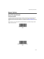
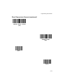
Beeper Options
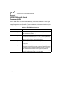
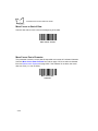
Beep After Good Decode
Parameter # 38h
This parameter determines if the imager’s beeper sounds during normal scanning. By
default, the beeper sounds after a decode. In all cases, the beeper operates during
parameter menu scanning and indicates error conditions. See Beeper Definitions on page
1-12.
Select whether or not to beep after a successful decode. If you select to beep, set the
beeper volume and tone.
*Beep After Good Decode
(01h)
Do Not Beep After Good Decode
(00h)
2-15
VS 4000 Series Product Reference Guide
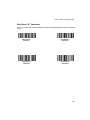
Beeper Volume
Parameter # 8Ch
This parameter sets the decode beep volume — low, medium, or high.
Low
(00h)
*Medium
(03h)
High
(09h)
2-16
Programming the VS 4000
Beeper Tone
Parameter # 91h
This parameter sets the decode beep frequency or tone — low, medium, or high.
Low Tone
(02h)
*Medium Tone
(01h)
High Tone
(00h)
2-17
VS 4000 Series Product Reference Guide
Imaging Options
The following parameters control image capture characteristics. Image capture occurs in
all modes of operation, including decode, video, and snapshot.
Generally, to brighten an image turn on illumination first, increase exposure time second,
then increase gain. To darken an image, reduce gain first, remove illumination second, and
reduce exposure time last.
To determine the optimal setting for manual exposure control:
1. Set the exposure time to 20 ms, the gain to 256, and the illumination on.
2. If these settings are too bright, reduce the gain. If it is still too bright, remove
illumination. If it is still too bright, reduce the exposure time.
3. If the settings are too dark, increase the exposure time if this does not result in
blurred images (e.g., if the VS 4000 is in a fixed mount). If the images are blurry,
restore the exposure time to 20 ms. If the images are still too dark, increase the
gain.
This procedure produces images that are optimized to only one light setting, so if the
amount of ambient light changes, the quality of the images change. To avoid these
problems, we recommend that you enable the Autoexposure feature. When Autoexposure
is enabled, you can still control illumination.
2-18
Programming the VS 4000
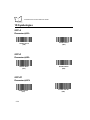
Decoding Autoexposure
Parameter # F0h,29h
Select Enable Autoexposure to allow the imager to control gain settings and exposure
(integration) time to best capture an image for the selected operation mode.
Select Disable Autoexposure to manually adjust the gain and exposure time (see the
following pages). This option is only recommended for advanced users with difficult image
capture situations.
*Enable Decoding Autoexposure
(01h)
Disable Decoding Autoexposure
(00h)
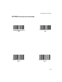
Decoding Illumination
Parameter # F0h,2Ah
If you select Enable Illumination, the imager flashes on every image capture. Select Disable
Illumination to prevent the imager from using artificial illumination.
Enabling illumination usually results in superior images. The effectiveness of the
illumination decreases as the distance to the target is increased.
*Enable Decoding Illumination
(01h)
Disable Decoding Illumination
(00h)
2-19
VS 4000 Series Product Reference Guide
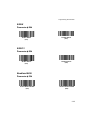
Image Capture Autoexposure
Parameter # F0h,68h
Select Enable Autoexposure to allow the imager to control gain settings and exposure
(integration) time to best capture an image for the selected operation mode.
Select Disable Autoexposure to manually adjust the gain and exposure time (see the
following pages). This option is only recommended for advanced users with difficult image
capture situations.
*Enable Image Capture
Autoexposure
(01h)
Disable Image Capture
Autoexposure
(00h)
Image Capture Illumination
Parameter # F0h,69h
If you select Enable Illumination, the imager flashes on every image capture. Select Disable
Illumination to prevent the imager from using artificial illumination.
Enabling illumination usually results in superior images. The effectiveness of the
illumination decreases as the distance to the target is increased.
*Enable Image Capture
Illumination
(01h)
2-20
Disable Image Capture
Illumination
(00h)
Programming the VS 4000
Gain
Parameter # F0h,37h
This parameter only applies when Decoding or Image Capture Autoexposure is disabled.
Gain is a means of amplifying the raw image data before it is converted into 256 gray-scale
values. Increasing the gain increases brightness and contrast, but also increases noise
(undesired electrical fluctuations in the image) which makes the image less attractive and/
or harder to decode. You may set the manual gain to one of the following values: 128, 192,
256, 320, 384 or 448.
Gain 128
(0080h)
*Gain 192
(00C0h)
Gain 256
(0100h)
Gain 320
(0140h)
Gain 384
(0180h)
Gain 448
(01C0h)
2-21
VS 4000 Series Product Reference Guide
Exposure Time
Parameter # F0h,38h
This parameter is only available when Decoding or Image Capture Autoexposure is
disabled. Exposure Time controls the amount of time the CCD is allowed to collect light,
much like the shutter speed for a camera. Generally, the brighter the environment, the lower
the exposure time. You may set the manual exposure time to one of the following values:
5 ms, 10 ms, 15 ms, 20 ms, 25 ms or 30 ms. As the exposure time is increased past 20 ms,
there is a risk of blurring the image due to hand jitter.
2-22
5 ms
(004Fh)
10 ms
(009Dh)
15 ms
(00ECh)
*20 ms
(013Bh)
25 ms
(018Ah)
30 ms
(01D8h)
Programming the VS 4000
Decode Aiming Pattern
Parameter # F0h,32h
This parameter only applies when in Decode Mode. Select Enable Decode Aiming Pattern
to project the aiming pattern during bar code capture, or Disable Decode Aiming Pattern to
turn the aiming pattern off.
Disable Decode Aiming Pattern
(00h)
*Enable Decode Aiming Pattern
(02h)
Snapshot Mode Timeout
Parameter # F0h,43h
This parameter sets the amount of time the imager remains in Snapshot Mode. The imager
exits Snapshot Mode when you pull the trigger, or when the Snapshot Mode Timeout
elapses. To set this timeout value, scan the bar code below followed by a bar code from
Numeric Bar Codes on page 2-91. The default value is 0 which represents 30 seconds;
values increment by 30. For example, 1 = 60 seconds, 2 = 90 seconds, etc.
Snapshot Mode Timeout
2-23
VS 4000 Series Product Reference Guide
Snapshot Aiming Pattern
Parameter # F0h,2Ch
Select Enable Snapshot Aiming Pattern to project the aiming pattern when in Snapshot
Mode, or Disable Snapshot Aiming Pattern to turn the aiming pattern off.
*Enable Snapshot Aiming Pattern
(01h)
Disable Snapshot Aiming Pattern
(00h)
Image Cropping
Parameter # F0h,2Dh
This parameter allows you to crop a captured image. If Disable Image Cropping is selected,
the full 640 x 480 pixels are presented. If Enable is selected, the imager crops the image
to the pixel addresses set in Crop to Pixel Addresses on page 2-25.
Enable Image Cropping
(01h)
2-24
*Disable Image Cropping
(Use Full 640 x 480 Pixels)
(00h)
Programming the VS 4000
Crop to Pixel Addresses
Parameter # F0h,3Bh (Top)
Parameter # F0h,3Ch (Left)
Parameter # F0h,3Dh (Bottom)
Parameter # F0h,3Eh (Right)
If Enable Image Cropping is selected, set the pixel addresses from (0,0) to (639,479) to
crop to.
Columns are numbered from 0 to 639, rows from 0 to 479. Specify four values for Top, Left,
Bottom, and Right, where Top and Bottom correspond to row pixel addresses, and Left and
Right correspond to column pixel addresses. For example, for a 4 row x 8 column image in
the extreme bottom-right section of the image, set the following values:
Top = 476, Bottom = 479, Left = 631, Right = 639
To set the pixel address to crop to, scan each Pixel Address bar code followed by three bar
codes from Numeric Bar Codes, beginning on page 2-91, which represent the value.
Leading zeros are required, so to enter a value of 3, for example, scan 0, 0, 3.
2-25
VS 4000 Series Product Reference Guide
Crop to Pixel Addresses (continued)
Top Pixel Address
(0 - 479 Decimal)
Left Pixel Address
(0 - 639 Decimal)
Bottom Pixel Address
(0 - 479 Decimal)
Right Pixel Address
(0 - 639 Decimal)
2-26
Programming the VS 4000
Image Resolution
Parameter # F0h,2Eh
This option alters image resolution before compression. Multiple pixels are combined to
one pixel, resulting in a smaller image containing the original content with reduced
resolution.
The following values can be selected:
*Full Resolution
(00h)
1/3 Resolution
(02h)
Resolution
Value
Image Size
Full
640 x 480
1/2
320 x 240
1/3
214 x 160
1/4
160 x 120
1/2 Resolution
(01h)
1/4 Resolution
(03h)
2-27
VS 4000 Series Product Reference Guide
JPEG Image Options
Parameter # F0h,2Bh
JPEG images may be optimized for either size or for quality. Scan the Quality Selector bar
code to enter a quality value; the imager then selects the corresponding image size. Scan
the Size Selector bar code to enter a size value; the imager then selects the best image
quality.
*JPEG Quality Selector
(01h)
JPEG Size Selector
(00h)
JPEG Quality and Size Value
JPEG Quality = Parameter # F0h,31h
JPEG Size = Parameter # F0h,33h
If JPEG Quality Selector is selected, scan the JPEG Quality Value bar code followed by 3
bar codes from Numeric Bar Codes, beginning on page 2-91, corresponding to a value from
5 to 100, where 100 represents the highest quality image.
If JPEG Size Selector is selected, scan JPEG Size Value followed by 3 bar codes from
Numeric Bar Codes, beginning on page 2-91, corresponding to a value from 1 to 150 which
represents the file size in multiples of 1024 bytes (1K). For example, setting this value to 8
(008) permits the file size to be as large as 8192 bytes.
JPEG Quality Value
(Default: 065)
(5 - 100 Decimal)
2-28
JPEG Size Value
(Default: 040)
(1 - 150 Decimal)
Programming the VS 4000
Image File Format Selector
Parameter # F0h,30h
Select an image format appropriate for your system (BMP, TIFF, or JPEG). The imager
stores captured images in the format you select.
BMP File Format
(03h)
*JPEG File Format
(01h)
TIFF File Format
(04h)
2-29
VS 4000 Series Product Reference Guide
Bits per Pixel
Parameter # F0h,2Fh
Select the number of significant bits per pixel (BPP) to use when capturing an image. Select
1BPP for a black and white image, 4BPP to assign 1 of 16 levels of grey to each pixel, or
8BPP to assign 1 of 256 levels of grey to each pixel. The imager ignores these settings for
JPEG files, which always use 8BPP.
1 BPP
(00h)
4 BPP
(01h)
*8 BPP
(02h)
2-30
Programming the VS 4000
Video Options
Video View Finder
Parameter # F0h,44h
Select Enable Video View Finder to project the video view finder while in Video Mode, or
Disable Video View Finder to turn the video view finder off.
*Disable Video View Finder
(00h)
Enable Video View Finder
(01h)
2-31
VS 4000 Series Product Reference Guide
Target Video Frame Size
Parameter # F0h,48h
Select the number of 100-byte blocks to be transmitted per second. Selecting a smaller
value allows more frames to be transmitted per second but reduces video quality; selecting
a larger value increases video quality but slows transmission.
To set the Target Video Frame Size, scan the bar code below followed by 2 bar codes from
Numeric Bar Codes, beginning on page 2-91, corresponding to the 100-byte value from 800
to 3300 bytes. For example, to select 1500 bytes, enter 1, 5. To select 900 bytes, enter 0, 9.
Target Video Frame Size
Video View Finder Image Size
Parameter # F0h,49h
Select the number of 100-byte blocks. Values range from 800 to 3300 bytes. Selecting a
smaller value allows more frames to be transmitted per second; selecting a larger value
increases video quality.
To set the Target Video Frame Size, scan the bar code below followed by 2 bar codes from
Numeric Bar Codes, beginning on page 2-91, corresponding to the 100-byte value from 800
to 3300 bytes. For example, to select 1500 bytes, enter 1, 5. To select 900 bytes, enter 0, 9.
Video View Finder Image Size
2-32
Programming the VS 4000
Bar Code Symbologies
The imager can decode any or all of the following symbologies. Select the symbologies you
need to scan using the bar codes in this section.
•
UPC Versions A and E (EAN 8 and 13) ♦
•
Code 39
♦
UCC/EAN 128
•
Code 39 Full ASCII
♦
ISBT 128
•
Trioptic Code 39
♦
Interleaved 2 of 5
•
Code 93
♦
Discrete 2 of 5
•
MSI Plessey
♦
Codabar
•
PDF417
♦
US Postnet
•
MicroPDF
♦
US Planet
•
Australian Postal
♦
Australian Postal
•
Japan Postal
♦
Maxicode
•
QR Code
♦
Data Matrix (ECC 200)
•
Bookland EAN
Code 128
The integrated decoder autodiscriminates between all these symbologies, except between
Code 39 and Code 39 Full ASCII.
Code 39/Code 39 Full ASCII
The ASCII character set assigns a code to letters, punctuation marks, numerals, and most
control keystrokes on the keyboard.
The first 32 codes are non-printable and are assigned to keyboard control characters, such
as BACKSPACE and RETURN. The other 96 are called printable codes because all but
SPACE and DELETE produce visible characters.
Code 39 Full ASCII interprets the bar code control character ($ + % /) preceding a Code 39
symbol and assigns an ASCII character value. For example, when Code 39 Full ASCII is
enabled and a +B is scanned, it is interpreted as b, %J as ?, and $H emulates the keystroke
BACKSPACE. Scanning ABC$M outputs the keystroke equivalent of “ABC ENTER”.
2-33
VS 4000 Series Product Reference Guide
1D Symbologies
UPC-A
Parameter # 01h
*Enable UPC-A
(01h)
Disable UPC-A
(00h)
UPC-E
Parameter # 02h
*Enable UPC-E
(01h)
Disable UPC-E
(00h)
UPC-E1
Parameter # 0Ch
Enable UPC-E1
(01h)
2-34
*Disable UPC-E1
(00h)
Programming the VS 4000
EAN-8
Parameter # 04h
*Enable EAN-8
(01h)
Disable EAN-8
(00h)
EAN-13
Parameter # 03h
*Enable EAN-13
(01h)
Disable EAN-13
(00h)
Bookland EAN
Parameter # 53h
Enable Bookland EAN
(01h)
*Disable Bookland EAN
(00h)
2-35
VS 4000 Series Product Reference Guide
Code 39
Parameter # 00h
*Enable Code 39
(01h)
Disable Code 39
(00h)
Code 39 Full ASCII
Parameter # 11h
Enable Code 39 Full ASCII
(01h)
*Disable Code 39 Full ASCII
(00h)
Trioptic Code 39
Parameter # 0Dh
Enable Trioptic Code 39
(01h)
2-36
*Disable Trioptic Code 39
(00h)
Programming the VS 4000
Code 93
Parameter # 09h
Enable Code 93
(01h)
*Disable Code 93
(00h)
Code 128
Parameter # 08h
*Enable Code 128
(01h)
Disable Code 128
(00h)
UCC/EAN 128
Parameter # 0Eh
*Enable UCC/EAN-128
(01h)
Disable UCC/EAN-128
(00h)
2-37
VS 4000 Series Product Reference Guide
ISBT 128
Parameter # 54h
*Enable ISBT 128
(01h)
Disable ISBT 128
(00h)
Codabar
Parameter # 07h
Enable Codabar
(01h)
*Disable Codabar
(00h)
Interleaved 2 of 5
Parameter # 06h
Enable I 2 of 5
(01h)
2-38
*Disable I 2 of 5
(00h)
Programming the VS 4000
Discrete 2 of 5
Parameter # 05h
Enable Discrete 2 Of 5
(01h)
*Disable Discrete 2 Of 5
(00h)
MSI Plessey
Parameter # 0Bh
Enable MSI Plessey
(01h)
*Disable MSI Plessey
(00h)
Postal Codes
US Postnet
Parameter # 59h
*Enable US Postnet
(01h)
Disable US Postnet
(00h)
2-39
VS 4000 Series Product Reference Guide
US Planet
Parameter # 5Ah
*Enable US Planet
(01h)
Disable US Planet
(00h)
UK Postal
Parameter # 5Bh
*Enable UK Postal
(01h)
Disable UK Postal
(00h)
Japan Postal
Parameter # F0h,22h
*Enable Japan Postal
(01h)
2-40
Disable Japan Postal
(00h)
Programming the VS 4000
Australian Postal
Parameter # F0h,23h
*Enable Australian Postal
(01h)
Disable Australian Postal
(00h)
2D Symbologies
PDF417
Parameter # 0Fh
*Enable PDF417
(01h)
Disable PDF417
(00h)
MicroPDF417
Parameter # E3h
Enable MicroPDF417
(01h)
*Disable MicroPDF417
(00h)
2-41
VS 4000 Series Product Reference Guide
Data Matrix
Parameter # F0h,24h
*Enable Data Matrix
(01h)
Disable Data Matrix
(00h)
Maxicode
Parameter # F0h,26h
*Enable Maxicode
(01h)
Disable Maxicode
(00h)
QR Code
Parameter # F0h,25h
*Enable QR Code
(01h)
2-42
Disable QR Code
(00h)
Programming the VS 4000
Code Lengths
Code lengths for certain one-dimensional code types (i.e., Code 39, Codabar, etc.) may be
set for any length, one or two discrete lengths, or lengths within a specific range. The length
of a code refers to the number of characters (i.e., human readable characters) the code
contains.
Table 2-2. Code Length Options
Length Option
Description
Length Within Range
This option allows you to decode a 1D symbol within a specified range. For
example, to decode a Code 39 symbol containing between 4 and 12
characters, first scan Code 39 Length Within Range. Then scan 0, 4, 1 and
2 (single-digit numbers must always be preceded by a leading zero).
One Discrete Length
This option allows you to decode only 1D codes containing a selected
length. For example, if you select Codabar - One Discrete Length, then
scan 1 and 4, only Codabar codes containing 14 characters are decoded.
No discrete lengths can be set for Code 128.
Two Discrete Lengths
This option allows you to decode only 1D codes containing two selected
lengths. For example, if you select I 2 Of 5 Two Discrete Lengths, then
scan 0, 2, 1, 4, only Interleaved 2 of 5 codes containing 2 or 14 characters
are decoded. No discrete lengths can be set for Code 128.
Any Length
Scanning this option allows you to decode the selected 1D code type
containing any number of characters. For example, if you scan Codabar
Any Length, you can decode a Codabar symbol containing any number of
characters.
To select lengths for each code type:
1. Scan the desired option.
2. Scan two Numeric Bar Codes, beginning on page 2-91, for each desired length.
For example, for a length of “12”, scan “1” then “2”. For a length of “3”, scan “0”,
then “3”. You must always scan two bar codes for each length.
3. If you make an error, or wish to change your selection, scan Cancel on page 2-92.
2-43
VS 4000 Series Product Reference Guide
Code 39 Lengths
L1 = Parameter # 12h; L2 = Parameter # 13h
Code 39 Any Length
*Code 39 Length Within Range
(0 - 55 decimal)
Code 39 1 Discrete Length
(0 - 55 decimal)
Code 39 2 Discrete Lengths
(0 - 55 decimal)
2-44
Programming the VS 4000
Code 93 Lengths
L1 = Parameter # 1Ah; L2 = Parameter # 1Bh
Code 93 Any Length
*Code 93 Length Within Range
(0 - 55 decimal)
Code 93 1 Discrete Length
(0 - 55 decimal)
Code 93 2 Discrete Lengths
(0 - 55 decimal)
2-45
VS 4000 Series Product Reference Guide
Codabar Lengths
L1 = Parameter # 18h; L2 = Parameter # 19h
Codabar Any Length
*Codabar Length Within Range
(0 - 55 decimal)
Codabar 1 Discrete Length
(0 - 55 decimal)
Codabar 2 Discrete Lengths
(0 - 55 decimal)
2-46
Programming the VS 4000
Interleaved 2 of 5 Lengths
L1 = Parameter # 16h; L2 = Parameter # 17h
I 2 Of 5 - Any Length
I 2 Of 5 - Length Within Range
(0 - 55 decimal)
*I 2 Of 5 1 Discrete Length
(14 Characters)
(0 - 55 decimal)
I 2 Of 5 2 Discrete Lengths
(0 - 55 decimal)
2-47
VS 4000 Series Product Reference Guide
Discrete 2 of 5 Lengths
L1 = Parameter # 14h; L2 = Parameter # 15h
D 2 Of 5 Any Length
D 2 Of 5 Length Within Range
(0 - 55 decimal)
*D 2 Of 5 1 Discrete Length
(12 Characters)
(0 - 55 decimal)
D 2 Of 5 2 Discrete Lengths
(0 - 55 decimal)
2-48
Programming the VS 4000
MSI Plessey Lengths
L1 = Parameter # 1Eh; L2 = Parameter # 1Fh
MSI Plessey - Any Length
*MSI Plessey - Length Within Range
(0 - 55 decimal)
MSI Plessey 1 Discrete Length
(0 - 55 decimal)
MSI Plessey 2 Discrete Lengths
(0 - 55 decimal)
2-49
VS 4000 Series Product Reference Guide
Decode Options
Transmit UPC-A Check Digit
Parameter # 28h
Select if decoded UPC-A symbols are transmitted with or without a check digit.
*Transmit UPC-A Check Digit
(01h)
Do Not Transmit UPC-A Check Digit
(00h)
Transmit UPC-E Check Digit
Parameter # 29h
Select if decoded UPC-E symbols are transmitted with or without a check digit.
*Transmit UPC-E Check Digit
(01h)
2-50
Do Not Transmit UPC-E Check Digit
(00h)
Programming the VS 4000
Transmit UPC-E1 Check Digit
Parameter # 2Ah
Select if decoded UPC-E1 symbols are transmitted with or without a check digit.
*Transmit UPC-E1 Check Digit
(01h)
Do Not Transmit UPC-E1 Check Digit
(00h)
Convert UPC-E to UPC-A
Parameter # 25h
This parameter converts UPC-E (zero suppressed) decoded data to UPC-A format before
transmission. After conversion, data follows UPC format and is affected by UPC-A
programming selections (e.g., Preamble, Check Digit).
Convert UPC-E To
UPC-A
(01h)
*Do Not Convert
UPC-E To UPC-A
(00h)
2-51
VS 4000 Series Product Reference Guide
Convert UPC-E1 to UPC-A
Parameter # 26h
This parameter converts UPC-E1 (zero suppressed) decoded data to UPC-A format before
transmission. After conversion, data follows UPC format and is affected by UPC-A
programming selections (e.g., Preamble, Check Digit).
Convert UPC-E1
To UPC-A
(01h)
2-52
*Do Not Convert
UPC-E1 To UPC-A
(00h)
Programming the VS 4000
Decode UPC/EAN Supplementals
Parameter # 10h
Supplementals are additionally appended characters (2 or 5) according to specific code
format conventions (e.g., UPC A+2, UPC E+2, EAN 8+2). Three options are available.
•
If UPC/EAN with supplemental characters is selected, the imager does not decode
UPC/EAN symbols without supplemental characters.
•
If UPC/EAN without supplemental characters is selected, and the imager is
presented with a UPC/EAN plus supplemental symbol, it decodes the UPC/EAN
and ignores the supplemental characters.
•
An autodiscriminate option is also available. If you scan this option, also select a
value for Decode UPC/EAN Supplemental Redundancy on page 2-54. A value of
5 or more is recommended.
Note: To minimize the risk of invalid data transmission, we recommend
that you select whether to read or ignore supplemental characters.
Select the desired option by scanning one of the following bar codes.
Decode UPC/EAN With
Supplementals
(01h)
*Ignore UPC/EAN With
Supplementals
(00h)
Autodiscriminate UPC/EAN Supplementals
(02h)
2-53
VS 4000 Series Product Reference Guide
Decode UPC/EAN Supplemental Redundancy
Parameter # 50h
With Autodiscriminate UPC/EAN Supplementals selected, this option adjusts the number
of times a symbol without supplementals is decoded before transmission. The range is from
2 to 20 times. Five or above is recommended when decoding a mix of UPC/EAN symbols
with and without supplementals.
Scan the bar code below to select a decode redundancy value. Next scan two numeric bar
codes beginning on page 2-91. Single digit numbers must have a leading zero. If you make
an error, or wish to change your selection, scan the Cancel bar code on page 2-92.
Decode UPC/EAN
Supplemental Redundancy
EAN-8 Zero Extend
Parameter # 27h
This parameter adds five leading zeros to decoded EAN-8 symbols to make them
compatible in format to EAN-13 symbols.
Enable EAN-8
Zero Extend
(01h)
2-54
*Disable EAN-8
Zero Extend
(00h)
Programming the VS 4000
Convert EAN-8 to EAN-13 Type
Parameter # E0h
When EAN Zero Extend is enabled, this parameter gives you the option of labeling the
extended symbol as either an EAN-13 bar code, or an EAN-8 bar code. This affects
Transmit Code ID Character and DECODE_DATA message.
When EAN Zero Extend is disabled, this parameter has no effect on bar code data.
Type Is EAN-8
(01h)
Type Is EAN-13
(00h)
UPC/EAN Coupon Code
Parameter # 55h
When enabled, this parameter decodes UPC-A, UPC-A with 2 supplemental characters,
UPC-A with 5 supplemental characters, and UPC-A/EAN128 bar codes.
Autodiscriminate UPC/EAN Supplementals must be selected.
Enable UPC/EAN
Coupon Code
(01h)
*Disable UPC/EAN
Coupon Code
(00h)
2-55
VS 4000 Series Product Reference Guide
UPC-A/UPC-E Preamble
There are three options for the lead-in characters of decoded UPC-A, UPC-E, or UPC-E1
symbols transmitted to the host device. Select a preamble for each of the UPC decodes
(UPC-A, UPC-E, and UPC-E1). These lead-in characters are considered part of the symbol
itself. The three options are:
•
a system character only
•
the country code and system character
•
no preamble.
The system character is the digit printed to the extreme left of a UPC symbol. The country
code for UPC is always zero, and it cannot be transmitted without the system character.
UPC-A Preamble
Parameter # 22h
Select an option for the UPC-A preamble by scanning the appropriate bar code.
None
(00h)
*System Character
(01h)
2-56
System Character &
Country Code
(02h)
Programming the VS 4000
UPC-E Preamble
Parameter # 23h
Select an option for the UPC-E preamble by scanning the appropriate bar code.
None
(00h)
System Character &
Country Code
(02h)
*System Character
(01h)
UPC-E1 Preamble
Parameter # 24h
Select an option for the UPC-E1 preamble by scanning the appropriate bar code.
None
(00h)
*System Character
(01h)
System Character &
Country Code
(02h)
2-57
VS 4000 Series Product Reference Guide
Code 39 Check Digit Verification
Parameter # 30h
When enabled, this parameter checks the integrity of a Code 39 symbol to ensure that it
complies with specified algorithms. Only those Code 39 symbols which include a modulo
43 check digit are decoded when this parameter is enabled.
Enable Code 39
Check Digit
(01h)
*Disable Code 39
Check Digit
(00h)
Transmit Code 39 Check Digit
Parameter # 2Bh
When Code 39 Check Digit Verification is enabled, select if you want to transmit data with
or without the check digit.
Transmit Code 39 Check
Digit (Enable)
(01h)
2-58
*Do Not Transmit Code 39
Check Digit (Disable)
(00h)
Programming the VS 4000
Convert Code 39 to Code 32
Parameter # 56h
Scan the appropriate bar code below to enable or disable converting Code 39 to Code 32.
Note: Code 39 must be enabled in order for this parameter to function.
Convert Code 39 to Code 32
(01h)
Do Not Convert Code 39 to Code 32
(00h)
Code 32 Prefix
Parameter # E7h
Scan the appropriate bar code below to enable or disable adding the prefix character “A”
to all Code 32 bar codes.
Note: Convert Code 39 to Code 32 must be enabled for this parameter to
function.
*Code 32 Prefix Enable
(01h)
Code 32 Prefix Disable
(00h)
2-59
VS 4000 Series Product Reference Guide
I 2 of 5 Check Digit Verification
Parameter # 31h
When enabled, this parameter checks the integrity of an I 2 of 5 symbol to ensure it
complies a specified algorithm, either Uniform Symbology Specification (USS), or Optical
Product Code Council (OPCC).
USS Check Digit
(01h)
*Disable
(00h)
OPCC Check Digit
(02h)
Transmit I 2 of 5 Check Digit
Parameter # 2Ch
Select if decoded I 2 of 5 symbols are transmitted with or without a check digit.
Transmit I 2 Of 5
Check Digit
(01h)
2-60
*Do Not Transmit
I 2 Of 5 Check Digit
(00h)
Programming the VS 4000
Convert I 2 of 5 to EAN-13
Parameter # 52h
This parameter converts a 14 character I 2 of 5 code into EAN-13, and transmits to the host
as EAN-13. To accomplish this, the I 2 of 5 code must be enabled, one length must be set
to 14, and the code must have a leading zero and a valid EAN-13 check digit.
Convert I 2 Of 5 To
EAN-13
(01h)
*Do Not Convert I 2 Of 5 To
EAN-13
(00h)
MSI Plessey Check Digits
Parameter # 32h
These check digits at the end of the bar code verify the integrity of the data. At least one
check digit is always required. Check digits are not automatically transmitted with the data.
*One MSI Plessey
Check Digit
(00h)
Two MSI Plessey
Check Digits
(01h)
2-61
VS 4000 Series Product Reference Guide
Transmit MSI Plessey Check Digit
Parameter # 2Eh
Select if you want to transmit data with or without the check digit.
Transmit MSI Plessey
Check Digit
(01h)
*Do Not Transmit MSI
Plessey Check Digit
(00h)
MSI Plessey Check Digit Algorithm
Parameter # 33h
When two MSI Plessey Check Digits are selected, an additional verification is required to
ensure integrity. Select either the Mod 10/Mod 10 or Mod 11/Mod 10 algorithm.
MOD 11/MOD 10
(00h)
2-62
*MOD 10/MOD 10
(01h)
Programming the VS 4000
Transmit US Postal Check Digit
Parameter # 5Fh
Select if you want to transmit US Postal data with or without the check digit.
*Transmit US Postal
Check Digit
(01h)
Do Not Transmit US Postal
Check Digit
(00h)
2-63
VS 4000 Series Product Reference Guide
CLSI Editing
Parameter # 36h
When enabled, this parameter strips the start and stop characters and inserts a space after
the first, fifth, and tenth characters of a 14-character Codabar symbol.
Note: Symbol length does not include start and stop characters.
Enable CLSI Editing
(01h)
*Disable CLSI Editing
(00h)
NOTIS Editing
Parameter # 37h
When enabled, this parameter strips the start and stop characters from a decoded Codabar
symbol.
Enable NOTIS Editing
(01h)
2-64
*Disable NOTIS Editing
(00h)
Programming the VS 4000
Code 128 Emulation
Parameter # 7Bh
When this parameter is enabled, the imager transmits data from certain MicroPDF417
symbols as if it was encoded in Code 128 symbols. Transmit AIM Symbology Identifiers
must be enabled for this parameter to work.
If Code 128 Emulation is enabled, these MicroPDF417 symbols are transmitted with the
one of the following prefixes:
]C1
if the first codeword is 903-907, 912, 914, 915
]C2
if the first codeword is 908 or 909
]C0
if the first codeword is 910 or 911
If disabled, they are transmitted with one of the following prefixes:
]L3
if the first codeword is 903-907, 912, 914, 915
]L4
if the first codeword is 908 or 909
]L5
if the first codeword is 910 or 911
Scan a bar code below to enable or disable Code 128 Emulation.
Enable Code 128 Emulation
(01h)
Disable Code 128 Emulation
(00h)
2-65
VS 4000 Series Product Reference Guide
Transmit Code ID Character
Parameter # 2Dh
A code ID character identifies the code type of a scanned bar code. This may be useful
when the imager is decoding more than one code type. If a prefix is selected, the code ID
character is sent after the prefix and before the decoded symbol.
You may select no code ID character, a Symbol code ID character, or an AIM ID character.
Symbol code ID characters are listed below. AIM ID characters are listed in AIM Code
Identifiers on page A-1.
Table 2-3. Symbol Code ID Characters
Code Type
2-66
Symbol Identifier
UPC-A, UPC-E, UPC-E1, EAN-13, EAN-8
A
Code 39, Code 39 Full ASCII, Code 32
B
Codabar
C
Code 128, ISBT 128
D
Code 93
E
Interleaved 2 of 5
F
Discrete 2 of 5, D 2 of 5 IATA
G
MSI Plessey
J
EAN 128
K
Bookland EAN
L
Trioptic Code 39
M
Coupon Code
N
PDF417, Micro PDF
X
Data Matrix
P00
QR Code
P01
MaxiCode
P02
US Postnet
P03
US Planet
P04
Japan Postal
P05
UK Postal
P06
Australian Postal
P09
Programming the VS 4000
Transmit Code ID Character (continued)
Transmit Symbol Code ID Character
(02h)
Transmit AIM Code ID Character
(01h)
*Do Not Transmit Code ID Character
(00h)
2-67
VS 4000 Series Product Reference Guide
Transmit “No Decode” Message
Parameter # 5Eh
When this feature is enabled, the imager transmits “NR” (No Read), along with enabled
prefixes and suffixes, if the trigger is released before a successful decode.
Transmit “No Decode” Message
(01h)
*Do Not Transmit
“No Decode” Message
(00h)
LRC Checksum
Parameter # 7Eh
When this option is enabled, it allows an LRC checksum character to be appended at the
end of a decode transmission. The format of output data is as follows:
<STX> <DATA...> <ETX> <LRC>.
If <DATA...> contains the special characters STX, ETX, and DLE, a DLE character is added
as an escape character before each special character, to instruct the host not to interpret
the special characters in the data as control characters. The LRC character is the exclusive
OR of all characters (including STX, ETX, and any DLE escape characters inserted) except
for the LRC character itself.
Enable LRC Checksum
(01h)
2-68
*Disable LRC Checksum
(00h)
Programming the VS 4000
Prefix/Suffix Values
Prefix = Parameter # 69h; Suffix = Parameter # 68h
A prefix/suffix may be appended to scanned data for use in data editing. Set these values
by scanning a four digit number (i.e., four bar codes) that correspond to ASCII characters
for various terminals. See Table A-3 on page A-7 for ASCII values.
To set a Prefix/Suffix value:
1. Scan the Scan Suffix or Scan Prefix bar code.
2. Scan four Numeric Bar Codes, beginning on page 2-91, which correspond to the
ASCII value or keystroke value you wish to assign (see Table A-3 on page A-7).
The Enter key is the default for all options.
3. If you make an error, or wish to change your selection, scan Cancel on page 2-92.
Scan Suffix (Value 1)
Scan Prefix (Value 2)
2-69
VS 4000 Series Product Reference Guide
Data Transmission Formats
Parameter # EBh
You may select one of the following scan data format options:
Standard:
<data>
Option 1:
<data> <SUFFIX>
Option 2:
<PREFIX> <data> <SUFFIX>
Option 3:
<PREFIX> <data>
<data> = scanned bar code data
<PREFIX> and <SUFFIX> as selected by the user.
To select a data transmission format:
1. Scan the Scan Options bar code.
2. Scan the bar code corresponding to the desired converted data format.
3. Scan Enter. If you make a mistake, scan Cancel on the next page.
Note: RS-232C hosts treat the extended keypad default suffix (7013) as
ASCII data.
Scan Options
*Data As Is
(00h)
2-70
<DATA> <SUFFIX>
(01h)
Programming the VS 4000
Data Transmission Formats (continued)
<PREFIX> <DATA> <SUFFIX>
(05h)
<PREFIX> <DATA>
(04h)
Enter
Cancel
2-71
VS 4000 Series Product Reference Guide
Security Options
Linear Code Type Security Level
Parameter # 4Eh
Note: This option does not apply to Code 128.
The VS 4000 offers four levels of decode security for linear code types (e.g., Code 39,
Interleaved 2 of 5). Select higher security levels for decoding poor quality bar codes. As
security levels increase, the imager’s aggressiveness decreases to prevent misdecodes.
Select the security level appropriate for your bar code quality.
Linear Security Level 1
The following code types must be successfully read twice before being decoded:
Code Type
Length
Codabar
All
MSI Plessey
4 or less
D 2 of 5
8 or less
I 2 of 5
8 or less
Linear Security Level 1
(01h)
2-72
Programming the VS 4000
Linear Security Level 2
All code types must be successfully read twice before being decoded.
*Linear Security Level 2
(02h)
Linear Security Level 3
Code types other than the following must be successfully read twice before being decoded.
The following codes must be read three times:
Code Type
Length
MSI Plessey
4 or less
D 2 of 5
8 or less
I 2 of 5
8 or less
Codabar
8 or less
Linear Security Level 3
(03h)
Linear Security Level 4
All code types must be successfully read three times before being decoded.
Linear Security Level 4
(04h)
2-73
VS 4000 Series Product Reference Guide
UPC/EAN Security Level
Parameter # 4Dh
The VS 4000 offers four levels of decode security for UPC/EAN bar codes. Select higher
security levels for decoding poor quality bar codes. As security levels increase, the
imager’s aggressiveness decreases to prevent misdecodes, so be sure to choose only that
level of security necessary for your application.
Table 2-4. UPC/EAN Security Levels
UPC/EAN Security Level
Description
UPC/EAN Security Level 0
This is the default setting which allows the imager to operate in its most
aggressive state, while providing sufficient security in decoding “inspec” UPC/EAN bar codes.
UPC/EAN Security Level 1
As bar code quality levels diminish, certain characters become prone
to misdecodes before others (i.e., 1, 2, 7, 8). If you are experiencing
misdecodes of poorly printed bar codes, and the misdecodes are
limited to these characters, select this security level.
UPC/EAN Security Level 2
If you are experiencing misdecodes of poorly printed bar codes, and
the misdecodes are not limited to characters 1, 2, 7, and 8, select this
security level.
UPC/EAN Security Level 3
If you have tried Security Level 2, and are still experiencing
misdecodes, select this security level. Be advised, selecting this option
is an extreme measure against misdecoding severely out of spec bar
codes. Selection of this level of security significantly impairs the
decoding ability of the imager. If this level of security is necessary, you
should try to improve the quality of your bar codes.
2-74
Programming the VS 4000
UPC/EAN Security Level (continued)
*UPC/EAN Security Level 0
(00h)
UPC/EAN Security Level 2
(02h)
UPC/EAN Security Level 1
(01h)
UPC/EAN Security Level 3
(03h)
2-75
VS 4000 Series Product Reference Guide
Host Communication Options
Baud Rate
Parameter # 9Ch
Baud rate is the number of bits of data transmitted per second. The imager's baud rate
settings should match the data rate settings of the host and auxiliary devices. If not, data
may not reach the devices or may reach them in distorted form.
Set the baud rate for transmission.
2-76
600
(2 decimal)
1200
(3 decimal)
2400
(4 decimal)
4800
(5 decimal)
Programming the VS 4000
Baud Rate (continued)
*9600
(6 decimal)
28800
(9 decimal)
57600
(10 decimal)
19200
(7 decimal)
38400
(8 decimal)
115200
(11 decimal)
2-77
VS 4000 Series Product Reference Guide
Parity
Parameter # 9Eh
A parity check bit is the most significant bit of each ASCII coded character and is helpful in
detecting transmission errors.
If you select Odd parity, the parity bit has a value 0 or 1, based on data, to ensure that an
odd number of 1 bits are contained in the coded character. If you select Even parity, the
parity bit has a value 0 or 1, to ensure that an even number of 1 bits are contained in the
coded character.
Set the type of parity for data transmission.
Odd
(00h)
Even
(01h)
*None
(04h)
Check Parity
Parameter # 97h
Select whether or not the parity of received characters is checked. The type of parity used
is selectable through the Parity parameter.
*Check Parity
(01h)
2-78
Do Not Check Parity
(00h)
Programming the VS 4000
Stop Bit Select
Parameter # 9Dh
The stop bit(s) at the end of each transmitted character marks the end of transmission of
one character and prepares the receiving device for the next character in the serial data
stream. The number of stop bits (one or two) selected depends on the number the receiving
terminal is programmed to accommodate. Set the number of stop bits to match host device
requirements.
Select the desired number of stop bits for serial communications.
*1 Stop Bit
(01h)
2 Stop Bits
(02h)
Hardware Handshaking
Parameter # A0h
The host exchanges data with the imager via a serial port, either with or without the
hardware handshaking lines, Request to Send (RTS), and Clear to Send (CTS).
Standard RTS/CTS
If Standard RTS/CTS handshaking is selected, scanned data is transmitted according to
the following sequence:
•
The CTS line must initially be deasserted by the host. If the imager detects that
CTS is asserted (indicating that the host may still be receiving a previous
transmission), the imager waits up to 2 seconds for the host to deassert the CTS
line. If, after 2 seconds (default), the CTS line is still asserted, the imager sounds
a transmit error and any scanned data is lost.
•
When the CTS line is deasserted, the imager asserts the RTS line and waits up to
2 seconds for the host to assert CTS. When the host asserts CTS, the imager
transmits the data. If, after 2 seconds (default), the CTS line is not asserted, the
imager sounds a transmit error and discards the data.
2-79
VS 4000 Series Product Reference Guide
•
When data transmission is complete, the imager deasserts RTS 10 msec after
sending the last character.
•
The host responds by deasserting CTS. The imager checks for a deasserted CTS
upon the next transmission of data.
During data transmission, the CTS line is asserted. If CTS is asserted for less than 50 ms
between characters, the transmission is aborted, the imager sounds a transmission error,
and the data is discarded.
If the previous communications sequence fails, the imager issues an error beep. In this
case, the data is lost and must be rescanned.
Note: The DTR signal is jumpered active.
Other RTS/CTS Options
The following options offer alternatives to Standard RTS/CTS Handshaking.
•
RTS/CTS Option 1: The imager asserts RTS before transmitting and ignores the
state of CTS. The imager deasserts RTS when the transmission is complete.
•
RTS/CTS Option 2: RTS is always high or low (user-programmed logic level).
However, the imager waits for CTS to be asserted before transmitting data. If CTS
is not asserted within two seconds, the imager issues an error beep and discards
the data.
•
RTS/CTS Option 3: The imager asserts RTS before transmitting, regardless of the
state of CTS. The imager waits up to two seconds for CTS to be asserted. If CTS
is not asserted during this time, the imager issues an error beep and discards the
data. The imager deasserts RTS when transmission is complete.
•
RTS/CTS PC: Standard RTS/CTS hardware handshaking used by the PC. The
host can deassert CTS to prevent the imager from transmitting, and the imager can
deassert RTS to prevent the host from transmitting.
2-80
Programming the VS 4000
Hardware Handshaking
*None
(00h)
RTS/CTS Option 1
(02h)
RTS/CTS Option 3
(04h)
Standard RTS/CTS
(01h)
RTS/CTS Option 2
(03h)
RTS/CTS PC
(05h)
2-81
VS 4000 Series Product Reference Guide
Software Handshaking
Parameter # 9Fh
This parameter offers control of the data transmission process, and may be used in
conjunction with hardware handshaking. ACK/NAK handshaking may be combined with
ENQ handshaking.
Select the type of software handshaking protocol:
•
No Software Handshaking: Data is transmitted immediately.
•
ACK/NAK Only: When this option is selected, after transmitting data, the imager
expects either an ACK or NAK response from the host. If a NAK is received, the
imager transmits the same data again and waits for either an ACK or NAK. After
three unsuccessful attempts to send data when NAKs are received, the imager
issues an error beep and discards the data.
•
ENQ Only: When this option is selected, the imager waits for an ENQ character
from the host before transmitting data. If an ENQ is not received within 2 seconds,
the imager issues an error beep and discards the data. The host must transmit an
ENQ character at least every 2 seconds to prevent transmission errors.
•
ACK/NAK with ENQ: This combines the two previous handshaking options.
•
XON/XOFF: An XOFF character turns the imager transmission off until the imager
receives an XON character. There are two situations for XON/XOFF:
2-82
•
XOFF is received before the imager has data to send. When the imager has
data to send, it then waits for an XON character before transmission. The
imager waits up to 2 seconds to receive the XON. If the XON is not received
within this time, the imager issues an error beep and discards the data.
•
XOFF is received during a transmission. Data transmission then stops after
sending the current byte. When the imager receives an XON character, it sends
the rest of the data message. The imager waits indefinitely for the XON.
Programming the VS 4000
Software Handshaking (continued)
*None
(00h)
ACK/NAK
(01h)
ACK/NAK with ENQ
(02h)
ENQ Only
(03h)
XON/XOFF
(04h)
2-83
VS 4000 Series Product Reference Guide
Decode Data Packet Format
Parameter # EEh
This parameter selects whether decoded data is transmitted in raw format (unpacketed), or
transmitted with the packet format defined by the serial protocol.
If the raw format is chosen, ACK/NAK handshaking is disabled for decode data.
Send Raw Decode Data
(00h)
*Send Packeted Decode Data
(01h)
2-84
Programming the VS 4000
Intercharacter Delay
Parameter # 6Eh
Select the intercharacter delay option matching host device requirements. The
intercharacter delay gives the host system time to service its receiver and perform other
tasks between characters. Select from no delay to a 99 ms delay between the transmission
of each character.
To set a host communications intercharacter delay:
1. Scan the Intercharacter Delay bar code below.
2. To set the desired delay, scan two Numeric Bar Codes on page 2-91. You must
always scan two bar codes.
3. If you make an error, or wish to change your selection, scan Cancel on page 2-92.
Intercharacter Delay
(Default: 0)
2-85
VS 4000 Series Product Reference Guide
Host Serial RTS Line State
Parameter # 9Ah
This parameter sets the default host serial RTS line state to either high or low.
To select Low RTS, scan the bar code below.
*Host: Low RTS
(00h)
To select High RTS, scan the bar code below.
Host: High RTS
(01h)
2-86
Programming the VS 4000
Serial Response Timeout
Parameter # 9Bh
This parameter specifies how long the imager waits for an ACK, NAK or CTS from the host
before determining that a transmission error has occurred. This only applies when one of
the ACK/NAK software handshaking modes, or RTS/CTS hardware handshaking options,
is selected. The delay period can range from 0.0 to 8.0 seconds in 0.1 second increments.
To set a serial response timeout:
1. Scan the Serial Response Timeout bar code below.
2. Scan two Numeric Bar Codes, beginning on page 2-91, to select the desired
timeout. You must always scan two bar codes.
3. If you make an error, or wish to change your selection, scan Cancel on page 2-92.
Serial Response Timeout
(Default: 2.0)
2-87
VS 4000 Series Product Reference Guide
Beep On <BEL>
Parameter # 96h
When this parameter is enabled, the imager issues a beep when a <BEL> character is
detected on the serial data line. <BEL> is used to alert the user of an illegal entry or other
important event.
Select whether to enable or disable this parameter.
Beep On <BEL> Character
(01h)
*Do Not Beep On <BEL> Character
(00h)
Data Transmission - 7 or 8-Bit ASCII Data Format
Parameter # A2h
This parameter determines whether data transmissions occur in the 7-bit or 8-bit ASCII
format. Select this parameter according to the requirement of the receiving device. The
default value is 8-bit ASCII.
7-Bit
(07h)
2-88
*8-Bit
(08h)
Programming the VS 4000
Report Version
Scan the bar code below to report the version of software currently installed in the imager.
³
S
T
I
R
E
V
Report Software Version
2-89
VS 4000 Series Product Reference Guide
Macro PDF Features
Macro PDF is a special feature for concatenating multiple PDF symbols into one file. The
imager can decode symbols that are encoded with this feature, however, the 64K version
cannot buffer large sets of macro PDF symbols.
Caution
When printing, keep each Macro PDF sequence separate, as each sequence has unique identifiers. Do not mix bar codes from several Macro
PDF sequences, even if they encode the same data. When scanning Macro PDF sequences, scan the entire Macro PDF sequence without interruption. If you scan a mixed sequence, you get two long low beeps (Lo Lo) for
inconsistent file ID or inconsistent symbology error.
Flush Macro Buffer
This flushes the buffer of all decoded Macro PDF data stored to that point, transmits it to
the host device, and aborts from Macro PDF mode.
Flush Macro PDF Buffer
Abort Macro PDF Entry
This clears all currently-stored Macro PDF data in the buffer without transmission and
aborts from Macro PDF mode.
Abort Macro PDF Entry
2-90
Programming the VS 4000
Numeric Bar Codes
0
1
2
3
4
5
2-91
VS 4000 Series Product Reference Guide
Numeric Bar Codes
6
7
8
9
Cancel
2-92
Chapter 3
Advanced Data Formatting (ADF)
Introduction
Advanced Data Formatting (ADF) is a means of customizing, or editing, the data scanned
by the imager before transmitting the data to your host device. Scanned data can be edited
to suit your particular requirements.
ADF is implemented by scanning a related series of bar codes to create rules to apply to
the scanned data. These bar codes appear later in this chapter.
Rules: Criteria Linked to Actions
In ADF, data is customized through rules. These rules perform specific actions when the
data meets certain criteria. One rule may consist of single or multiple actions applied to
single or multiple criteria.
For instance, a data formatting rule could be the following:
Criteria:
When scan data is Code 39, length 12,
and data at the start position is the string “129”,
Actions: pad all sends with zeros to length 8,
send all data up to X,
send a space.
In this example, if a Code 39 bar code of 1299X1559828 is scanned, the following is
transmitted: 00001299<space>. If a Code 39 bar code of 1299X15598 is scanned, this rule
is ignored because the length (10 characters) does not pass the criteria.
The rule specifies the editing conditions and requirements before data transmission occurs.
3-1
VS 4000 Series Product Reference Guide
Using ADF Bar Codes
When you program a rule, make sure the rule is logically correct. Plan ahead before you
start scanning.
To program each data formatting rule:
1. Start the Rule. Scan the Begin New Rule bar code on page 3-11.
2. Criteria. Scan the bar codes for all pertinent criteria. Criteria can include code type
(e.g., Code 128), code length, or data that contains a specific character string (e.g.,
the digits “129”). These options are described in Criteria on page 3-14.
3. Actions. Scan all actions related to, or affecting, these criteria. The actions of a
rule specify how to format the data for transmission. These options are described
in Actions on page 3-27.
4. Save the Rule. Scan the Save Rule bar code on page 3-11. This places the rule
in the “top” position in the rule buffer.
If you make errors during this process, some special-purpose bar codes may be useful:
Erase Criteria and Start Again, Erase Actions and Start Again, Erase Previously
Saved Rule, and Erase All Rules. See Erase on page 3-12.
Beeper Definitions for ADF on page 3-8 help guide you through the programming steps.
3-2
Advanced Data Formatting (ADF)
ADF Bar Code Menu Example
This section provides an example of how to enter an ADF rule to apply to scanned data.
An auto parts distribution center wants to encode manufacturer ID, part number, and
destination code into their own Code 128 bar codes. The distribution center also has
products that carry UPC bar codes, placed there by the manufacturer. The Code 128 bar
codes have the following format:
MMMMMPPPPPDD
Where:
M = Manufacturer ID
P = Part Number
D = Destination Code
The distribution center uses a PC with dedicated control characters for manufacturer ID
<CTRL M>, part number <CTRL P>, and destination code <CTRL D>. At this center the
UPC data is treated as manufacturer ID code.
The following rules need to be entered:
When scanning data of code type Code 128, send the next 5 characters, send the
manufacturer ID key <CTRL M>, send the next 5 characters, send the part number
key <CTRL P>, send the next 2 characters, send the destination code key <CTRL
D>.
When scanning data of code type UPC/EAN, send all data, send the manufacturer
ID key <CTRL M>.
To enter these rules, follow these steps:
3-3
VS 4000 Series Product Reference Guide
Rule 1: The Code 128 Scanning Rule
Table 3-1. Code 128 Scanning Ru le
Step
Bar Code
On Page
Beep Indication
1
Begin New Rule
3-11
High High
2
Code 128
3-14
High High
3
Send next 5 characters
3-28
High High
4
Send <CTRL M>
3-56
High High
5
Send next 5 characters
3-28
High High
6
Send <CTRL P>
3-56
High High
7
Send next 2 characters
3-27
High High
8
Send <CTRL D>
3-54
High High
9
Save Rule
3-11
High Low High Low
Rule 2: The UPC Scanning Rule
Table 3-2. UPC Scanning Rule
Step
Bar Code
On Page
Beep Indication
1
Begin New Rule
3-11
High High
2
UPC/EAN
3-17
High High
3
Send all remaining data
3-27
High High
4
Send <CTRL M>
3-56
High High
5
Save Rule
3-11
High Low High Low
If you made any mistakes while entering this rule, scan the Quit Entering Rules bar code
on page 3-12. If you already saved the rule, scan the Erase Previously Saved Rule bar
code on page 3-12.
3-4
Advanced Data Formatting (ADF)
Alternate Rule Sets
ADF rules may be grouped into one of five alternate sets that can be turned on and off when
needed. This is useful when you want to format the same message in different ways. For
example, a Code 128 bar code contains the following information:
Class (2 digits), Stock Number (8) digits, Price (5 digits)
This bar code might look like this:
245671243701500
where:
Class = 24
Stock Number = 56712437
Price = 01500
Ordinarily you would send this data as follows:
24 (class key)
56712437 (stock key)
01500 (enter key)
But, when there is a sale, you may want to send only the following:
24 (class key)
56712437 (stock key)
and the cashier keys the price manually.
To implement this, first enter an ADF rule that applies in the normal situation. This rule may
look like this:
When scanning a bar code of length 15, send the next 2 characters, send the
class key, send the next 8 characters, send the stock key, send the data that
remains, send the Enter key.
The “sale” rule may look like this:
When scanning a bar code of length 15, send the next 2 characters, send the
class key, send the next 8 characters, send the stock key.
To switch between the two sets of rules, a “switching rule” must be programmed. This rule
specifies what type of bar code must be scanned to switch between the rule sets. For
3-5
VS 4000 Series Product Reference Guide
example, in the case of the “sale” rule above, the rule programmer wants the cashier to
scan the bar code “M” before a sale. To do this, a rule can be entered as follows:
When scanning a bar code of length 1 that begins with “M”, select rule set
number 1.
Another rule could be programmed to switch back.
When scanning a bar code of length 1 that begins with “N”, turn off rule set
number 1.
The switching back to normal rules can also be done in the “sale” rule. For example, the
rule may look like this:
When scanning a bar code of length 15, send the next 2 characters, send the
class key, send the next 8 characters, send the stock key, turn off rule set 1.
It is recommended that you scan the Disable All Rule Sets bar code after programming a
rule belonging to an alternate rule set.
In addition to enabling and disabling rule sets within the rules, you can disable them by
scanning the appropriate bar codes in Disable Rule Set on page 3-13.
Rules Hierarchy (in Bar Codes)
The order of programming individual rules is important. The most general rule should be
programmed first.
All programmed rules are stored in a buffer. As they are programmed, they are stored at
the “top” of a rules list. If three rules have been created, the list would be configured as
follows:
Third Rule
Second Rule
First Rule
When data is scanned, the rules list is checked from top to bottom to determine if the criteria
matches (and therefore, if the actions should occur). Input is modified into the data format
specified by the first matching set of criteria it finds. Be sure that your most general rule is
the first one programmed.
For example, if the THIRD rule states:
When scanning a bar code of any length, send all data, then send the ENTER key.
3-6
Advanced Data Formatting (ADF)
And the SECOND rule states:
When scanning a Code 128 bar code of length 12, send the first four characters,
then send the ENTER key, then send all remaining data.
If a Code 128 bar code of length 12 were scanned, the THIRD rule would be in effect. The
SECOND rule would appear to not function.
Note also that ADF rules are actually created when you use the standard data editing
functions. Scan options are entered as ADF rules, and the hierarchy mentioned above also
applies to them. For the VS 4000, this applies to prefix/suffix programming in the parameter
Scan Data Transmission Format.
These rules reside in the same “rule list” as ADF Rules, so the order of their creation is also
important.
Default Rules
Every unit has a default rule to send all scan data. Units with custom software may have
one or more default rules burned in. The rules hierarchy checks user programmable rules
first, then the default rules. Default rules can be disabled by entering the following general
rule in the user programmable buffer:
When receiving scan data, send all data.
Since this rule always applies, ADF will never go into the default rules.
3-7
VS 4000 Series Product Reference Guide
Beeper Definitions for ADF
The following table defines beep sequences that occur during rule entry.
Table 3-3. Beeper Definition s
Beeper Sequence
Indication
Normal Data Entry. Duration of tones are short.
High-Low
Entry of a number is expected. Enter another digit. Add leading
zeros to the front if necessary.
Low-Low
Entry of an alphabetic character is expected. Enter another
character or scan the End of Message bar code.
High-High
Entry of Criterion/Action is expected. Enter another criterion or
action, or scan the Save Rule bar code.
High-Low-High-Low
Rule saved. Rule entry mode exited.
High-Low-Low
All criteria or actions were cleared for rule currently being entered;
continue entry of rule.
Low
Last saved rule was successfully deleted. The rule presently being
entered is left intact.
Low-High-High
All rules are now deleted. The rule presently being entered is left
intact. (This beep sequence has a different meaning outside of
ADF.)
Error Indications. Duration of tones are very long.
Low-High-Low-High
Out of rule memory. Erase some existing rules, then try to save rule
again. (The current rule need not be re-entered.)
Low-High-Low
Cancel rule entry. Rule entry mode exited because of an error or the
user asked to exit rule entry.
Low-High
Entry error, wrong bar code scanned. Re-enter criterion or action.
All previously entered criteria and actions are retained. Criteria or
action list is too long for a rule.
3-8
Advanced Data Formatting (ADF)
ADF Bar Codes
The following table helps you locate the bar codes you need to create an ADF rule.
Table 3-4. ADF Bar Codes
Bar Code
Description
Page
Special Commands
Begin New Rule
Starts data formatting rule.
3-11
Save Rule
Completes and saves rule.
3-11
Erase
Erases criteria, actions, or rules.
3-12
Quit Entering Rules
Quits entering rules.
3-12
Disable Rule Set
Disables rule sets.
3-13
Code Types
Selects code types to be affected by rule.
3-14
Code Lengths
Defines the number of characters each code type must
contain.
3-18
Message Containing A
Specific Data String
Select whether formatting affects data that begins with or
contains a specific character or data string.
3-23
Numeric Keypad
Used for specifying a data string.
3-24
Rule Belongs To Set
Selects which set a rule belongs to.
3-26
Send Data
Sends all data that remains, sends all data up to a specific
character, or sends N characters.
3-27
Setup Field(s)
Moves the cursor in relation to a specified character.
3-31
Set Preset Value
Sends prefix and suffix values.
3-39
Criteria
Actions
3-9
VS 4000 Series Product Reference Guide
Table 3-4. ADF Bar Codes
Bar Code
Modify Data
! Remove All Spaces
! Crunch All Spaces
! Stop Space Removal
! Remove Leading Zeros
! Stop Zero Removal
! Pad Data With Spaces
! Pad Data With Zeros
Beeps
Description
Page
Modifies data as follows:
Removes all spaces in the send commands.
! Leaves one space between words.
! Stops space removal.
! Removes all leading zeros.
! Stops removal of zeros.
! Pads data to the left with spaces.
! Pads data to the left with zeros.
3-41
3-41
3-41
3-41
3-42
3-42
3-43
3-48
Selects beep sequence for each rule.
3-53
!
Specifies control and keyboard characters to send.
Send Keystroke
Control Characters
! Sends control characters.
! Keyboard Characters
! Sends keyboard characters.
! Send ALT Characters
! Sends ALT characters.
! Send Command
! Sends command characters.
Characters
! Send Special Characters
! Sends special characters.
! Send Keypad Characters ! Sends keypad characters.
! Send Function Keys
! Sends function keys.
3-54
3-54
3-59
3-71
3-75
Turn On/Off Rule Sets
Turns rule sets on and off.
3-88
Alphanumeric Keyboard
Used to specify characters and strings when creating a rule. 3-89
!
3-10
3-77
3-78
3-82
Advanced Data Formatting (ADF)
Special Commands
Bar codes and explanations of the following special commands are provided on the next
few pages.
•
Begin New Rule
•
Save Rule
•
Erase
•
Quit Entering Rules
•
Disable Rule Set
Begin New Rule
Scan this bar code to start entering a new data formatting rule.
Begin New Rule
Save Rule
Scan this bar code to complete and save the rule you entered.
Save Rule
3-11
VS 4000 Series Product Reference Guide
Erase
Use these bar codes to erase criteria, actions, or rules.
Erase Actions And
Start Again
Erase Criteria And
Start Again
Erase Previously
Saved Rule
Erase All Rules
Quit Entering Rules
Scan this bar code to quit entering rules.
Quit Entering Rules
3-12
Advanced Data Formatting (ADF)
Disable Rule Set
Use these bar codes to disable rule sets.
Disable Rule Set 1
Disable Rule Set 2
Disable Rule Set 3
Disable Rule Set 4
Disable All Rule Sets
3-13
VS 4000 Series Product Reference Guide
Criteria
Code Types
Select any number of code types to be affected. All selected codes must be scanned in
succession, prior to selecting other criteria. If you don't select a code type, all code types
are affected.
Codabar
Code 39
EAN 128
Code 128
Discrete 2 Of 5
I 2 Of 5
UPC-A
3-14
Advanced Data Formatting (ADF)
Code Types (continued)
UPC-E1
EAN-8
EAN-13
PDF417
MSI/Plessey
Code 93
Bookland EAN
3-15
VS 4000 Series Product Reference Guide
Code Types (continued)
US Postnet
US Planet
UK Postal
Japan Postal
MaxiCode
Australian Postal
Datamatrix
3-16
Advanced Data Formatting (ADF)
Code Types (continued)
UPC-E
IATA 2 of 5
Trioptic 39
QR Code
3-17
VS 4000 Series Product Reference Guide
Code Lengths
Define the number of characters the selected code type must contain. Select one length
per rule only. If you don't select a code length, selected code types of any length are
affected.
Note: These codes are used to set the code length only; this is not a
keypad.
3-18
1
2
3
4
5
6
Advanced Data Formatting (ADF)
Code Lengths (continued)
7
8
9
10
11
12
3-19
VS 4000 Series Product Reference Guide
Code Lengths (continued)
13
15
17
3-20
14
16
18
Advanced Data Formatting (ADF)
Code Lengths (continued)
19
20
21
22
23
24
3-21
VS 4000 Series Product Reference Guide
Code Lengths (continued)
25
3-22
26
27
28
29
30
Advanced Data Formatting (ADF)
Message Containing A Specific Data String
Select whether the formatting affects data that begins with a specific character or data
string, or contains a specific character or data string.
Specific String at Start
To apply formatting to data that begins with a specific character or data string:
1. Scan the bar code below.
2. Enter a string representing the desired character or characters (up to a total of 8)
using the Alphanumeric Keyboard beginning on page 3-89.
3. Scan End Of Message on page 3-98.
Specific String At Start
Specific String, Any Location
To apply formatting to data that contains a specific character or data string:
1. Scan the bar code below.
2. Scan a two-digit number representing the position (include a leading “zero” if
necessary) using the Numeric Keypad on page 3-24.
3. Enter the desired character or characters (up to a total of 8) using the
Alphanumeric Keyboard beginning on page 3-89.
4. Scan End Of Message on page 3-98.
Specific String Any Location
Any Message OK
By not scanning any bar code, all selected code types are formatted, regardless of
information contained.
3-23
VS 4000 Series Product Reference Guide
Numeric Keypad
Bar codes on this page should not be confused with those on the alphanumeric keyboard.
0
2
4
3-24
1
3
5
Advanced Data Formatting (ADF)
Numeric Keypad (continued)
Bar codes on this page should not be confused with those on the alphanumeric keyboard.
7
6
8
9
Cancel
3-25
VS 4000 Series Product Reference Guide
Rule Belongs To Set
Scan a bar code below to select which set a rule belongs to.
Rule Belongs To Set 1
Rule Belongs To Set 2
Rule Belongs To Set 3
Rule Belongs To Set 4
3-26
Advanced Data Formatting (ADF)
Actions
Select how to format the data meeting the defined criteria before transmission.
Send Data
Use the following bar codes to send all data that remains, send all data up to a specific
character selected from the Alphanumeric Keyboard on page 3-89, or send the next N
characters. N = any number from 1 to 254, selected from the Alphanumeric Keyboard on
page 3-89.
Send Data Up To
Character
Send All Data
That Remains
Send Next 2 Characters
Send Next Character
Send Next 3 Characters
3-27
VS 4000 Series Product Reference Guide
Send Data (continued)
Send Next 4 Characters
Send Next 6 Characters
Send Next 8 Characters
Send Next 10 Characters
3-28
Send Next 5 Characters
Send Next 7 Characters
Send Next 9 Characters
Send Next 11 Characters
Advanced Data Formatting (ADF)
Send Data (continued)
Send Next 12 Characters
Send Next 14 Characters
Send Next 16 Characters
Send Next 13 Characters
Send Next 15 Characters
Send Next 17 Characters
3-29
VS 4000 Series Product Reference Guide
Send Data (continued)
Send Next 18
Characters
Send Next 19
Characters
Send Next 20
Characters
Send Next 50
Characters
Send Next 100
Characters
Send Next 150
Characters
Send Next 200
Characters
3-30
Send Next 250
Characters
Advanced Data Formatting (ADF)
Pause Duration
For transmissions using Synapse, use the following bar codes to insert a pause at any point
in the data transmission. Scan the Send Pause bar code, then the Pause Duration bar
code, and then two bar codes from the Numeric Bar Codes on page 2-91. A pause is
measured in 1/10 second intervals. For example, scanning bar codes “0” and “1” inserts a
1/10 second pause; “0” and “5” inserts a 1/2 second pause.
Pause Duration
Send Pause
Setup Field(s)
Use the following bar codes to move the cursor in relation to a specified character.
Note: If there is no match when the rule is interpreted and the rule fails, the
next rule is checked.
Move Cursor To a Character
Scan the Move Cursor To Character bar code, then any printable ASCII character from
the Alphanumeric Keyboard on page 3-89. This moves the cursor to the position after the
matching character. If the character is not there, the rule fails and ADF tries the next rule.
Move Cursor To
Character
3-31
VS 4000 Series Product Reference Guide
Move Cursor to Start of Data
Scan this bar code to move cursor to the beginning of the data.
Move Cursor To Start
Move Cursor Past a Character
This parameter moves the cursor past all sequential occurrences of a selected character.
Scan the Move Cursor Past Character bar code on page 3-32, then select a character
from the Alphanumeric Keyboard on page 3-89. If the character is not there, the cursor
does not move (i.e., has no effect).
Move Cursor Past
Character
3-32
Advanced Data Formatting (ADF)
Skip Ahead “N” Characters
Scan one of these bar codes to select the number of positions ahead you wish to move the
cursor.
Skip Ahead 1
Character
Skip Ahead 2
Characters
Skip Ahead 3
Characters
Skip Ahead 4
Characters
3-33
VS 4000 Series Product Reference Guide
Skip Ahead (continued)
Skip Ahead 5
Characters
Skip Ahead 7
Characters
Skip Ahead 9
Characters
3-34
Skip Ahead 6
Characters
Skip Ahead 8
Characters
Skip Ahead 10
Characters
Advanced Data Formatting (ADF)
Skip Ahead (continued)
Skip Ahead 50
Characters
Skip Ahead 100
Characters
Skip Ahead 150
Characters
Skip Ahead 200
Characters
Skip Ahead 250
Characters
3-35
VS 4000 Series Product Reference Guide
Skip Back “N” Characters
Scan one of these bar codes to select the number of positions back you wish to move the
cursor.
3-36
Skip Back 1
Characters
Skip Back 2
Characters
Skip Back 3
Characters
Skip Back 4
Characters
Advanced Data Formatting (ADF)
Skip Back (continued)
Skip Back 5
Characters
Skip Back 7
Character
Skip Back 9
Characters
Skip Back 6
Characters
Skip Back 8
Characters
Skip Back 10
Characters
3-37
VS 4000 Series Product Reference Guide
Skip Back (continued)
Skip Back 50
Characters
Skip Back 100
Characters
Skip Back 150
Characters
Skip Back 200
Characters
Skip Back 250
Characters
3-38
Advanced Data Formatting (ADF)
Set Preset Value
Set Values 1 through 6 by scanning the appropriate bar code and send the preset value by
scanning a bar code in Send Preset Value on page 3-40.
Value 1 = Scan Suffix
Value 2 = Scan Prefix
Value 3 = Scan Suffix 2
Use these bar codes to set the preset values.
Set Value 1
Set Value 2
Set Value 3
Set Value 4
Set Value 5
Set Value 6
3-39
VS 4000 Series Product Reference Guide
Send Preset Value
Send Values 1 through 6 by scanning the appropriate bar code. These values must be set
using Prefix / Suffix Values on page A-7 and bar codes in Set Preset Value on page 3-39.
Values 1, 2, and 3 are reserved for the following:
Value 1 = Scan Suffix
Value 2 = Scan Prefix
Value 3 = Scan Suffix 2
Use these bar codes to send preset values.
Send Value 1
Send Value 2
Send Value 3
Send Value 4
Send Value 5
3-40
Send Value 6
Advanced Data Formatting (ADF)
Modify Data
Modify data in the ways listed. The following actions work for all send commands that follow
it within a rule. If you program pad zeros to length 6, send next 3 characters, stop padding,
send next 5 characters, three zeros are added to the first send, and the next send is
unaffected by the padding. These options do not apply to the Send Keystroke or Send
Preset Value options.
Remove All Spaces
To remove all spaces in the send commands that follow, scan this bar code.
Remove All Spaces
Crunch All Spaces
To leave one space between words, scan this bar code. This also removes all leading and
trailing spaces.
Crunch All Spaces
Stop Space Removal
Scan this bar code to disable space removal.
Stop Space Removal
3-41
VS 4000 Series Product Reference Guide
Remove Leading Zeros
Scan this bar code to remove all leading zeros.
Remove Leading
Zeros
Stop Zero Removal
Scan this bar code to disable the removal of zeros.
Stop Zero Removal
3-42
Advanced Data Formatting (ADF)
Pad Data With Spaces
To pad data to the left, scan the bar code containing the desired number of spaces. This
parameter is activated by Send commands.
Pad Spaces To
Length 1
Pad Spaces To
Length 2
Pad Spaces To
Length 3
Pad Spaces To
Length 4
Pad Spaces To
Length 5
Pad Spaces To
Length 6
3-43
VS 4000 Series Product Reference Guide
Pad Data with Spaces (continued)
Pad Spaces To
Length 7
3-44
Pad Spaces To
Length 8
Pad Spaces To
Length 9
Pad Spaces To
Length 10
Pad Spaces To
Length 11
Pad Spaces To
Length 12
Advanced Data Formatting (ADF)
Pad Data with Spaces (continued)
Pad Spaces To
Length 13
Pad Spaces To
Length 14
Pad Spaces To
Length 15
Pad Spaces To
Length 16
Pad Spaces To
Length 17
Pad Spaces To
Length 18
3-45
VS 4000 Series Product Reference Guide
Pad Data with Spaces (continued)
Pad Spaces To
Length 19
3-46
Pad Spaces To
Length 20
Pad Spaces To
Length 21
Pad Spaces To
Length 22
Pad Spaces To
Length 23
Pad Spaces To
Length 24
Advanced Data Formatting (ADF)
Pad Data with Spaces (continued)
Pad Spaces To
Length 25
Pad Spaces To
Length 26
Pad Spaces To
Length 27
Pad Spaces To
Length 28
Pad Spaces To
Length 29
Pad Spaces To
Length 30
Stop Pad Spaces
3-47
VS 4000 Series Product Reference Guide
Pad Data With Zeros
To pad data to the left, scan the bar code containing the desired number of zeros. This
parameter is activated by Send commands. Use these bar codes to pad data with zeros.
3-48
Pad Zeros To
Length 1
Pad Zeros To
Length 2
Pad Zeros To
Length 3
Pad Zeros To
Length 4
Pad Zeros To
Length 5
Pad Zeros To
Length 6
Advanced Data Formatting (ADF)
Pad Data With Zeros (continued)
Pad Zeros To
Length 7
Pad Zeros To
Length 9
Pad Zeros To
Length 11
Pad Zeros To
Length 8
Pad Zeros To
Length 10
Pad Zeros To
Length 12
3-49
VS 4000 Series Product Reference Guide
Pad Data With Zeros (continued)
Pad Zeros To
Length 13
Pad Zeros To
Length 15
Pad Zeros To
Length 17
3-50
Pad Zeros To
Length 14
Pad Zeros To
Length 16
Pad Zeros To
Length 18
Advanced Data Formatting (ADF)
Pad Data With Zeros (continued)
Pad Zeros To
Length 19
Pad Zeros To
Length 20
Pad Zeros To
Length 21
Pad Zeros To
Length 22
Pad Zeros To
Length 23
Pad Zeros To
Length 24
3-51
VS 4000 Series Product Reference Guide
Pad Data With Zeros (continued)
Pad Zeros To
Length 25
Pad Zeros To
Length 26
Pad Zeros To
Length 27
Pad Zeros To
Length 28
Pad Zeros To
Length 30
Pad Zeros To
Length 29
Stop Pad Zeros
3-52
Advanced Data Formatting (ADF)
Beeps
Select a beep sequence for each ADF rule.
Beep Once
Beep Twice
Beep Three Times
3-53
VS 4000 Series Product Reference Guide
Send Keystroke (Control Characters and Keyboard
Characters)
Scan the “Send __” bar code for the keystroke you wish to send.
Control Characters
Scan these bar codes to send control characters.
3-54
Send Control 2
Send Control A
Send Control B
Send Control C
Send Control D
Send Control E
Advanced Data Formatting (ADF)
Control Characters (continued)
Send Control F
Send Control H
Send Control J
Send Control G
Send Control I
Send Control K
3-55
VS 4000 Series Product Reference Guide
Control Characters (continued)
Send Control L
Send Control N
Send Control P
3-56
Send Control M
Send Control O
Send Control Q
Advanced Data Formatting (ADF)
Control Characters (continued)
Send Control R
Send Control S
Send Control T
Send Control U
Send Control V
Send Control W
Send Control X
3-57
VS 4000 Series Product Reference Guide
Control Characters (continued)
Send Control Y
Send Control Z
Send Control [
Send Control \
Send Control ]
Send Control 6
Send Control -
3-58
Advanced Data Formatting (ADF)
Keyboard Characters
Use these bar codes to send keyboard characters.
Send Space
Send “
Send !
Send #
Send $
Send %
Send &
Send ‘
3-59
VS 4000 Series Product Reference Guide
Keyboard Characters (continued)
Send (
3-60
Send )
Send *
Send +
Send ,
Send -
Send .
Send /
Advanced Data Formatting (ADF)
Keyboard Characters (continued)
Send 0
Send 1
Send 2
Send 3
Send 4
Send 5
Send 6
Send 7
3-61
VS 4000 Series Product Reference Guide
Keyboard Characters (continued)
Send 8
Send 9
Send :
Send ;
Send <
Send =
Send >
3-62
Send ?
Advanced Data Formatting (ADF)
Keyboard Characters (continued)
Send @
Send A
Send B
Send C
Send D
Send E
Send F
Send G
3-63
VS 4000 Series Product Reference Guide
Keyboard Characters (continued)
Send H
3-64
Send I
Send J
Send K
Send L
Send M
Send N
Send O
Advanced Data Formatting (ADF)
Keyboard Characters (continued)
Send P
Send Q
Send R
Send S
Send T
Send U
Send V
Send W
3-65
VS 4000 Series Product Reference Guide
Keyboard Characters (continued)
3-66
Send X
Send Y
Send Z
Send [
Send \
Send ]
Send ^
Send _
Advanced Data Formatting (ADF)
Keyboard Characters (continued)
Send ‘
Send a
Send b
Send c
Send d
Send e
Send f
Send g
3-67
VS 4000 Series Product Reference Guide
Keyboard Characters (continued)
3-68
Send h
Send i
Send j
Send k
Send l
Send m
Send n
Send o
Advanced Data Formatting (ADF)
Keyboard Characters (continued)
Send p
Send q
Send r
Send s
Send t
Send u
Send v
Send w
3-69
VS 4000 Series Product Reference Guide
Keyboard Characters (continued)
Send y
Send x
Send z
Send {
Send |
Send }
Send ~
3-70
Advanced Data Formatting (ADF)
Send ALT Characters
Use these bar codes to send ALT characters
Send ALT 2
Send ALT A
Send ALT B
Send ALT C
Send ALT D
Send ALT E
Send ALT F
Send ALT G
3-71
VS 4000 Series Product Reference Guide
Send ALT Characters (continued)
3-72
Send ALT H
Send ALT I
Send ALT J
Send ALT K
Send ALT L
Send ALT M
Send ALT N
Send ALT O
Advanced Data Formatting (ADF)
Send ALT Characters (continued)
Send ALT P
Send ALT Q
Send ALT R
Send ALT S
Send ALT T
Send ALT U
Send ALT V
Send ALT W
3-73
VS 4000 Series Product Reference Guide
Send ALT Characters (continued)
3-74
Send ALT X
Send ALT Y
Send ALT Z
Send ALT [
Send ALT \
Send ALT ]
Send ALT 6
Send ALT -
Advanced Data Formatting (ADF)
Send Command Characters
Send PA 1
Send CMD 1
Send CMD 3
Send PA 2
Send CMD 2
Send CMD 4
3-75
VS 4000 Series Product Reference Guide
Send Command Characters (continued)
Send CMD 5
Send CMD 7
Send CMD 9
3-76
Send CMD 6
Send CMD 8
Send CMD 10
Advanced Data Formatting (ADF)
Send Special Characters
Send Pound Sterling Character
Send Yen
Character
Send Hook
Character
Send Bomb
Character
Send Bullet
Character
Send 1/2
Character
Send Paragraph
Character
Send Section
Character
Send Vertical
Character
3-77
VS 4000 Series Product Reference Guide
Send Keypad Characters
3-78
Send Keypad *
Send Keypad +
Send Keypad -
Send Keypad .
Send Keypad /
Send Keypad 0
Send Keypad 1
Send Keypad 2
Send Keypad 3
Send Keypad 4
Advanced Data Formatting (ADF)
Send Keypad Characters (continued)
Send Keypad 5
Send Keypad 6
Send Keypad 7
Send Keypad 8
Send Keypad 9
Send Keypad ENTER
Send Keypad
NUM LOCK
3-79
VS 4000 Series Product Reference Guide
Send Keypad Characters (continued)
Send Break Key
Send Delete Key
Send Page Up Key
Send End Key
Send Page Down Key
Send Pause Key
Send Scroll Lock Key
Send Backspace Key
Send Tab Key
Send Print Screen Key
3-80
Advanced Data Formatting (ADF)
Send Keypad Characters (continued)
Send Insert Key
Send Home Key
Send Enter Key
Send Escape Key
Send Up Arrow Key
Send Down Arrow Key
Send Left Arrow Key
Send Right Arrow Key
Send Back Tab
Character
3-81
VS 4000 Series Product Reference Guide
Send Function Keys
3-82
Send F1 Key
Send F2 Key
Send F3 Key
Send F4 Key
Send F5 Key
Send F6 Key
Send F7 Key
Send F8 Key
Send F9 Key
Send F10 Key
Advanced Data Formatting (ADF)
Send Function Keys (continued)
Send F11 Key
Send F12 Key
Send F13 Key
Send F14 Key
Send F15 Key
Send F16 Key
Send F17 Key
Send F18 Key
Send F19 Key
Send F20 Key
3-83
VS 4000 Series Product Reference Guide
Send Function Keys (continued)
3-84
Send F21 Key
Send F22 Key
Send F23 Key
Send F24 Key
Send F25 Key
Send F26 Key
Send F27 Key
Send F28 Key
Send F29 Key
Send F30 Key
Advanced Data Formatting (ADF)
Send Function Keys (continued)
Send PF1 Key
Send PF2 Key
Send PF3 Key
Send PF4 Key
Send PF5 Key
Send PF6 Key
Send PF7 Key
Send PF8 Key
Send PF9 Key
Send PF10 Key
3-85
VS 4000 Series Product Reference Guide
Send Function Keys (continued)
3-86
Send PF11 Key
Send PF12 Key
Send PF13 Key
Send PF14 Key
Send PF15 Key
Send PF16 Key
Send PF17 Key
Send PF18 Key
Send PF19 Key
Send PF20 Key
Advanced Data Formatting (ADF)
Send Function Keys (continued)
Send PF21 Key
Send PF22 Key
Send PF23 Key
Send PF24 Key
Send PF25 Key
Send PF26 Key
Send PF27 Key
Send PF28 Key
Send PF29 Key
Send PF30 Key
3-87
VS 4000 Series Product Reference Guide
Turn On/Off Rule Sets
Use these bar codes to turn rule sets on and off within a rule.
Turn On Rule Set 1
Turn On Rule Set 2
Turn On Rule Set 3
Turn On Rule Set 4
Turn Off Rule Set 1
Turn Off Rule Set 2
Turn Off Rule Set 3
Turn Off Rule Set 4
3-88
Advanced Data Formatting (ADF)
Alphanumeric Keyboard
Space
#
$
%
*
+
-
.
3-89
VS 4000 Series Product Reference Guide
Alphanumeric Keyboard (continued)
/
!
“
&
‘
(
)
3-90
:
Advanced Data Formatting (ADF)
Alphanumeric Keyboard (continued)
;
<
=
>
?
@
3-91
VS 4000 Series Product Reference Guide
Alphanumeric Keyboard (continued)
\
[
]
_
3-92
^
`
Advanced Data Formatting (ADF)
Alphanumeric Keyboard (continued)
Bar codes on this page should not be confused with those on the numeric keypad.
0
1
3
2
4
5
3-93
VS 4000 Series Product Reference Guide
Alphanumeric Keyboard (continued)
Bar codes on this page should not be confused with those on the numeric keypad.
3-94
6
7
8
9
Advanced Data Formatting (ADF)
Alphanumeric Keyboard (continued)
A
B
C
D
E
F
G
H
3-95
VS 4000 Series Product Reference Guide
Alphanumeric Keyboard (continued)
3-96
I
J
K
L
M
N
O
P
Advanced Data Formatting (ADF)
Alphanumeric Keyboard (continued)
Q
R
S
T
U
V
3-97
VS 4000 Series Product Reference Guide
Alphanumeric Keyboard (continued)
W
Y
Cancel
3-98
X
Z
End Of Message
Advanced Data Formatting (ADF)
Alphanumeric Keyboard (continued)
a
b
c
d
e
f
g
h
3-99
VS 4000 Series Product Reference Guide
Alphanumeric Keyboard (continued)
3-100
i
j
k
l
m
n
o
p
Advanced Data Formatting (ADF)
Alphanumeric Keyboard (continued)
q
r
s
t
u
v
w
x
3-101
VS 4000 Series Product Reference Guide
Alphanumeric Keyboard (continued)
3-102
y
z
{
|
}
~
Chapter 4
Maintenance and Troubleshooting
Maintenance
The only maintenance required for the imager is periodic cleaning of the exit window.
•
Do not allow any abrasive material to touch the window.
•
Do not spray water or other cleaning liquids directly into the window.
•
Remove any dirt particles with a damp cloth.
•
Wipe the window using a tissue moistened with ammonia/water.
4-1
VS 4000 Series Product Reference Guide
Troubleshooting
If your imager is not functioning properly, review the following table to try to identify the
problem.
Problem
The aiming pattern in
the imager does not
illuminate when the
trigger is pressed.
The imager is having
trouble reading
symbols.
Possible Cause
Probable Solution
The interface cable is loose.
Check that the cable is connected
properly.
Power is not applied.
Be sure that power is supplied to the
imager via the host or a power supply.
The aiming pattern is not
enabled in the imager.
Enable the laser aiming parameter.
The symbology you are
scanning is not enabled.
Enable that the symbology.
The symbol is damaged.
Be sure the symbols aren’t smeared,
rough, scratched, or exhibiting voids.
Environmental conditions
inhibit the symbol’s quality.
Be sure the symbols aren’t coated with
frost or water droplets on the surface.
The symbol is not within the
aiming pattern.
Be sure the symbol is completely within
the area outlined by the aiming pattern.
Communication parameters Check that the communication parameters
The imager operates
but scanned data is not are inconsistent between the (baud rate, parity, stop bits, etc.) are set
properly for your host device.
imager and host.
displayed, or displays
incorrectly.
4-2
Appendix A
Programming Reference
AIM Code Identifiers
AIM is the industry standard for identifying the code type of a scanned bar code. You may
choose to transmit the AIM identifier with each bar code scanned using the Transmit Code
ID Character on page 2-66. Each AIM Code Identifier contains the three-character string
]cm where:
]
c
m
=
=
=
Flag Character (ASCII 93)
Code Character
Modifier Character
Table A-1. AIM Code Identifiers
Code Character
Code Type
A
Code 39, Code 32, Code 39 Full
ASCII
C
Code 128, ISBT 128
d
Data Matrix
E (note 1)
E + E (note 2)
UPC/EAN
EAN 8+2, EAN 8+5, EAN 13+2,
EAN 13+5, UPCA+2, UPCA+5,
UPCE+2, UPCE+5, UPCE1+2,
UPCE1+5
A-1
VS 4000 Series Product Reference Guide
Table A-1. AIM Code Identifiers (Continued)
Code Character
Code Type
F
Codabar
G
Code 93
I
Interleaved 2 of 5
L
PDF417, Micro PDF
M (note 3)
MSI Plessey
Q
QR Code
S
D 2 of 5, IATA 2 of 5
U
MaxiCode
X
Code 39 Trioptic, Bookland EAN,
Planet, Postal Codes, Coupon
Code
Notes:
1. UPCE, UPCE1, and UPCA are converted to EAN-13
for AIM ID.
2. E + E requires 2 AIM IDs; one ID prefixes the main
UPC/EAN block, the second ID prefixes the
supplemental block.
3. Presently does not conform to any AIM standard.
The modifier character is the sum of the applicable option values based on Table A-2.
Table A-2. Modifier Characters
Code Type
Code 39
A-2
Option Value
0
1
2
4
Option
No Check character or Full ASCII processing.
Reader has checked one check character.
Reader has stripped check character.
Reader has performed Full ASCII character
conversion.
Example: A Full ASCII bar code with check character
W, A+I+MI+DW, can be transmitted as ]A7AimId
where 7 = (1+2+4).
Programming Reference
Table A-2. Modifier Characters (Continued)
Code Type
Option Value
Option
Trioptic Code
39
0
No option specified at this time. Always transmit 0.
Example: A Trioptic bar code 412356 is transmitted
as ]X0412356.
Code 93
0
No option specified at this time. Always transmit 0.
Example: A Code 39 bar code 012345678905 is
transmitted as ]G0012345678905.
Code 128
0
Standard data packet, No Function code 1 in first
symbol position.
Function code 1 in first symbol character position.
Function code 1 in second symbol character position.
Example: A Code (EAN) 128 bar code with Function
1 character in the first position, Fcnt1AimId is
transmitted as ]C1AimId.
1
2
EAN/UPC
0
1
2
4
Standard packet in full EAN country code format,
which is 13 digits for UPC-A and UPC-E (not including
supplemental data).
Two digit supplement data only.
Five digit supplement data only.
EAN-8 data packet.
Example:A UPC-A bar code 012345678905 is
transmitted as ]E00012345678905.
Interleaved
2 of 5
0
1
2
No check digit processing.
Reader has checked check digit.
Reader has stripped check digit before transmission.
Example: An I 2 of 5 bar code without check digit,
4123, will be transmitted as ]I04123.
Discrete 2 of 5
0
No option specified at this time. Always transmit 0.
Example: A D 2 of 5 bar code 4123 is transmitted as
]S04123.
A-3
VS 4000 Series Product Reference Guide
Table A-2. Modifier Characters (Continued)
Code Type
MSI Plessey
Option Value
0
1
2
3
Single check digit checked.
Two check digits checked.
Single check digit verified and stripped before
transmission.
Two check digits verified and stripped before
transmission.
Example: An MSI Plessey bar code 4123, with a
single check digit checked, is transmitted as
]M04123.
Bookland EAN
0
No option specified at this time. Always transmit 0.
Example: A Bookland EAN bar code 123456789X is
transmitted as ]X0123456789X.
PDF417
0
Reader set to conform to protocol defined in 1994
PDF417 symbology specifications. Note: When this
option is transmitted, the receiver cannot reliably
determine whether ECIs have been invoked or
whether data byte 92DEC has been doubled in
transmission.
Reader set to follow the ECI protocol (Extended
Channel Interpretation). All data characters 92 DEC are
doubled.
Reader set for Basic Channel operation (no escape
character transmission protocol). Data characters
92DEC are not doubled. Note: When decoders are set
to this mode, unbuffered Macro symbols and symbols
requiring the decoder to convey ECI escape
sequences cannot be transmitted.
The bar code contains a UCC/EAN-128 symbol, and
the first codeword is 903-907, 912, 914, 915.
The bar code contains a UCC/EAN-128 symbol, and
the first codeword is in the range 908-909.
The bar code contains a UCC/EAN-128 symbol, and
the first codeword is in the range 910-911.
Example: A PDF417 bar code ABCD, with no
transmission protocol enabled, is transmitted as
]L2ABCD
1
2
3
4
5
A-4
Option
Programming Reference
Table A-2. Modifier Characters (Continued)
Code Type
Option Value
Option
MaxiCode
0
1
2
3
Mode 4 or
Mode 2 or
Mode 4 or
Mode 2 or
Data Matrix
0
1
2
3
4
5
ECC 000-140 (not supported).
ECC 200.
ECC 200, FNC1 in first or fifth position.
ECC 200, FNC1 in second or sixth position.
ECC 200 supporting ECI protocol.
ECC 200, FNC1 in first or fifth position, supporting
ECI protocol.
ECC 200, FNC1 in second or sixth position,
supporting ECI protocol.
6
5.
3.
5 with ECI.
3 with ECI.
Enable AIM ID Characters
To enable or disable AIM code ID characters, scan a bar code below. These bar codes can
also be found in Transmit Code ID Character on page 2-66.
A-5
VS 4000 Series Product Reference Guide
<FN3>2051701
Transmit AIM Code ID Character
<FN3>2051700
*Do Not Transmit Code ID Character
A-6
Programming Reference
Prefix / Suffix Values
The following values can be assigned as ASCII prefixes or suffixes to scanned data (see
Prefix/Suffix Values on page 2-69, and Set Preset Value on page 3-39).
Table A-3. Prefix/Suffix Values
Prefix/Suffix Value
1000
1001
1002
1003
1004
1005
1006
1007
1008
1009
1010
1011
1012
1013
1014
1015
1016
1017
1018
1019
1020
1021
1022
1023
1024
1025
1026
1027
1028
1029
Full ASCII Code
39 Encode Char.
%U
$A
$B
$C
$D
$E
$F
$G
$H
$I
$J
$K
$L
$M
$N
$O
$P
$Q
$R
$S
$T
$U
$V
$W
$X
$Y
$Z
%A
%B
%C
ASCII
Character
NUL
SOH
STX
ETX
EOT
ENQ
ACK
BELL
BCKSPC
HORIZ TAB
LF/NW LN
VT
FF
CR/ENTER
SO
SI
DLE
DC1
DC2
DC3
DC4
NAK
SYN
ETB
CAN
EM
SUB
ESC
FS
GS
Prefix/Suffix Value
1030
1031
1032
1033
1034
1035
1036
1037
1038
1039
1040
1041
1042
1043
1044
1045
1046
1047
1048
1049
1050
1051
1052
1053
1054
1057
1056
1057
1058
1059
Full ASCII Code
39 Encode Char.
%D
%E
Space
/A
/B
/C
/D
/E
/F
/G
/H
/I
/J
/K
/L
.
/
0
1
2
3
4
5
6
7
8
9
/Z
%F
ASCII
Character
RS
US
Space
!
"
#
$
%
&
‘
(
)
*
+
,
.
/
0
1
2
3
4
5
6
7
8
9
:
;
A-7
VS 4000 Series Product Reference Guide
Table A-3. Prefix/Suffix Values (Continued)
Prefix/Suffix Value
1060
1061
1062
1063
1064
1065
1066
1067
1068
1069
1070
1071
1072
1073
1074
1075
1076
1077
1078
1079
1080
1081
1082
1083
1084
1085
1086
1087
1088
1089
1090
1091
1092
1093
1094
A-8
Full ASCII Code
39 Encode Char.
%G
%H
%I
%J
%V
A
B
C
D
E
F
G
H
I
J
K
L
M
N
O
P
Q
R
S
T
U
V
W
X
Y
Z
%K
%L
%M
%N
ASCII
Character
<
=
>
?
@
A
B
C
D
E
F
G
H
I
J
K
L
M
N
O
P
Q
R
S
T
U
V
W
X
Y
Z
[
\
]
^
Prefix/Suffix Value
1095
1096
1097
1098
1099
1100
1101
1102
1103
1104
1105
1106
1107
1108
1109
1110
1111
1112
1113
1114
1115
1116
1117
1118
1119
1120
1121
1122
1123
1124
1125
1126
1127
7013
Full ASCII Code
39 Encode Char.
%O
%W
+A
+B
+C
+D
+E
+F
+G
+H
+I
+J
+K
+L
+M
+N
+O
+P
+Q
+R
+S
+T
+U
+V
+W
+X
+Y
+Z
%P
%Q
%R
%S
ASCII
Character
_
`
a
b
c
d
e
f
g
h
i
j
k
l
m
n
o
p
q
r
s
t
u
v
w
x
y
z
{
|
}
~
Undefined
ENTER
Programming Reference
Host Qualification of Trigger, RS-232 Host Mode
When enabled, the host application controls when the imager responds to a physical trigger
pull by sending a SYN (ASCII 22) character to the imager. This ensures that the imager only
responds to the trigger when the host is expecting data.
Note: If this mode is enabled accidentally or when not connected to a host that
provides the SYN character, hold the trigger for 5 seconds to override the
SYN character requirement, and enable scanning.
<FN3>14B0071
Enable Host Qualification
of Trigger
<FN3>14B0070
*Disable Host Qualification
of Trigger
A-9
VS 4000 Series Product Reference Guide
A-10
Appendix B
VS 4000 Imager Specifications
Technical Specifications
Table 2-1 lists the specifications for the imager.
Table 2-1. VS 4004HD-I000 Imager Specification s
Item
Description
Power Requirements:
Low Power Mode Current
Normal Current
Peak Current
+4.75V to 5.25V, 400 mA Typical
1.5 ma
400 ma
930 ma, duration 10 ms typical
Laser Diode Output Power
0.8 mW, max.
Field of View
32o horizontal typical
24o vertical typical
Optical Resolution
VS 4004: Can decode a 6.6 mil (minimum x-dimension)
PDF417 symbol; y-dimension must be 2X or greater.
VS 4004HD: Can decode a 5 mil (minimum x-dimension)
PDF417 symbol; y-dimension must be 2X or greater.
Angular Orientation Tolerances:
Pitch Tolerance
± 60o (“front to back”)
Skew
± 60o from plane parallel to symbol (“side-to-side”)
Rotational Tolerance
± 180 o
Print Contrast Resolution
25% (1-D symbologies) or 35% (PDF417) absolute dark/light
reflectance differential, measured at 650 nm.
B-1
VS 4000 Series Product Reference Guide
Table 2-1. VS 4004HD-I000 Imager Specifications (Continued)
Item
Description
Ambient Light Immunity
Up to 9000 ft-candles of sunlight
Humidity
5 - 70% (non-condensing)
Shock
Multiple 4-ft / 1.2m drops to concrete
Operating Temperature
0o to 40o C; 32o to 104o F
Storage Temperature
-20 o to 60 o C; -4o to 140o F
Imager Connector
10-pin modular connector at base of handle
Pin 1: Reserved
Pin 2: +5V power supply
Pin 3: Ground
Pin 4: Reserved for Synapse control data
Pin 5: Reserved for Synapse control clock
Pin 6: Receive (RxD)
Pin 7: Transmit (TxD)
Pin 8: Data Terminal Ready (DTR)
Pin 9: Clear to Send (CTS)
Pin 10: Request to Send (RTS)
Coil Cable Length
6 ft. / 1.8m
Weight
7.3 oz / 205 g (without cable)
Height
6.3 in. / 16 cm
Length
5 in. / 12.7 cm
Width
2.8 in. / 7.1 cm
Decode Capability
1-D Symbologies: UPC-A, UPC-E, UPC-E1, EAN-8, EAN-13,
Code 39, Code 39 Full ASCII, Trioptic Code 39, Code 93, Code
128, UCC/EAN 128, ISBT 128, Codabar, Interleaved 2 of 5,
Discrete 2 of 5, Bookland EAN, UPC Coupon Code, MSI
Plessey, US Postnet. Cannot autodiscriminate between Code
39 and Code 39 Full ASCII.
2-D Symbologies: PDF417 (up to 928 codewords at security
level 0 - 8), DataMatrix (ECC 200), Maxicode, Postal Codes
(US Planet, UK, Japanese, Australian), QR Code, Micro PDF.
Memory
B-2
4MB RAM, 1MB Flash
VS 4000 Imager Specifications
VS 4000 Decode Zones
The following illustrations provide the decode ranges for the standard and high-density
imager models, for both 1D and 2D bar code types.
Note: Typical performance at 68˚F (20˚C)
on high quality symbols.
Top of
imager
5 mil Code 39
4.2
7.5
13 mil UPC
2.3
4.4
In.
cm
0
0
2
5.1
4
10.1
Postnet
6
8
15.2 20.3
6
15.2
4
10.1
2
5.1
0
0
2
5.1
4
10.1
6
15.2
W
i
d
t
h
o
f
F
i
e
l
d
15.4
20 mil Code 39
3.1
cm
14.7
14 mil Code 128
3.1
In.
20.2
11.2
10
12
14
25.4 30.5 35.6
16
40.6
18
45.7
20
22
50.8 55.9
Depth of Field
Figure 2-1. VS 4004 (Standard) Decode Zone for 1-D Bar Codes
B-3
VS 4000 Series Product Reference Guide
Note: Typical performance at 68˚F (20˚C)
on high quality symbols.
Top of
imager
6.6 mil PDF
7.9
4.0
3.4
2.8
3.3
0
0
2
5.1
cm
4
10.1
2
5.1
0
0
2
5.1
4
10.1
10 mil QR
6.2
10 mil MicroPDF
9.5
10 mil PDF/Data Matrix
9.3
Maxicode
3.2
In.
cm
In.
4
10.1
6
8
15.2 20.3
14.0
10
12
14
25.4 30.5 35.6
16
40.6
Depth of Field
Figure 2-2. VS 4004 (Standard) Decode Zone for 2-D Bar Codes
B-4
W
i
d
t
h
o
f
F
i
e
l
d
VS 4000 Imager Specifications
Note: Typical performance at 68˚F (20˚C)
on high quality symbols.
Top of
imager
1.6
3.3 mil Code 39
In.
cm
3
7.6
2
5.0
1
2.5
0
0
1
2.5
2
5.0
3
7.6
3.7
5 mil Code 39
1.3
W
i
d
t
h
o
f
F
i
e
l
d
5.1
10 mil Code 39
7.0
2.1
13 mil UPC
1.8
4.5
In.
cm
0
0
1
2.5
2
5.1
3
7.6
4
10.1
Postnet
7.2
6.6
5
6
7
12.7 15.2 17.8
8
20.3
Depth of Field
Figure 2-3. VS 4004HD (High Density) Decode Zone for 1-D Bar Codes
B-5
VS 4000 Series Product Reference Guide
Note: Typical performance at 68˚F (20˚C)
on high quality symbols.
Top of
imager
10 mil QR
4.5
1.1
5 mil Micro PDF
3.3
1.8
In.
cm
2.5
6.2
1.25
3.2
0
0
1.25
3.2
2.5
6.2
W
i
d
t
h
o
f
F
i
e
l
d
5 mil PDF 417/Data Matrix
4.0
2.2
2.3
10 mil PDF417
1.7
0
0
1
2.5
2
5.1
5.6
Maxicode
2.3
In.
cm
5.3
10 mil Data Matrix
3
7.6
4
10.1
5
6
12.7 15.2
7.4
7
17.8
8
20.3
Depth of Field
Figure 2-4. VS 4004HD (High Density) Decode Zone for 2-D Bar Codes
B-6
VS 4000 Imager Specifications
Cable Pinouts
The following table describes the pinouts for the host end of the interface cable.
Table 2-2. Single-Port RS-232C, 9-Pin Female D-Type Connector (PC/AT)
P/N 25-16456-05
Pin
Signal
Function
2
TxD
Serial data transmit output. It drives the serial data receive
input on the device communicating with the imager.
3
RxD
Serial data receive input. It is driven by the serial data
transmit output on the device communicating with the
imager.
5
Ground
Power supply input ground pin and reference for both
output signals. It must be capable of sinking all return
current.
7
CTS
Clear-to-send handshaking input line. It may be used
optionally by another device to signal the imager that it
may begin transmitting data. It can be used only in
conjunction with the RTS line.
8
RTS
Request-to-send handshaking output line. It may be used
optionally by the imager to signal another device that data
is available to send. It can be used only in conjunction with
the CTS line.
B-7
VS 4000 Series Product Reference Guide
B-8
Glossary
ASCII
American Standard Code for Information Interchange. A 7
bit-plus-parity code representing 128 letters, numerals,
punctuation marks, and control characters. It is a standard
data transmission code in the U.S.
Asymmetric Width Growth
Non-uniform growth of elements in a printed symbol.
Autodiscrimination
The ability of an imager to determine the code type of a
scanned bar code. After this determination is made, the
information content can be decoded.
Average Bar Width Growth
Average deviation of bars from nominal widths over the
entire symbol.
Bad Check Digit
Error message resulting from failure of the check digit to
calculate properly.
Bad Data Character
Error message caused by failure of one or more data
characters to decode properly.
Bar
The dark element in a printed bar code symbol.
Bar Code Data Density
The number of characters represented per unit of
measurement (e.g., characters per inch in one-dimensional
symbologies, characters per square inch in PDF417).
Bar Code Print Density
The bar width of the smallest (thinnest) element in the bar
code.
Bar Height
The dimension of a bar measured perpendicular to the bar
width.
Glossary-1
VS 4000 Series Product Reference Guide
Bar Width
Thickness of a bar measured from the edge closest to the
symbol start character to the trailing edge of the same bar.
Bar Width Deviation
Increase or decrease in bar width as compared with
nominal bar width.
Baud Rate
A measure of the data flow or number of signaling events
occurring per second. When one bit is the standard "event,"
this is a measure of bits per second (bps). For example, a
baud rate of 50 means transmission of 50 bits of data per
second.
Bidirectional Reading
Capability
The ability to decode a symbol successfully by reading in
complementary (opposite) directions across bars and
spaces.
Bit
Binary digit. One bit is the basic unit of binary information.
Generally, eight consecutive bits compose one byte of data.
The pattern of 0 and 1 values within the byte determines its
"meaning."
Buffer
An area of memory allocated for data storage. In this
context, a buffer's data storage capacity is needed when
data can flow into the device more quickly than the device
can process that data. Buffering the data preserves it until
it can be processed.
Byte
On an addressable boundary, eight adjacent binary digits (0
and 1) combined in a pattern to represent a specific
character or numeric value. Bits are numbered from the
right, 0 through 7, with bit 0 the low-order bit. One byte in
memory can be used to store one ASCII character.
Character
A pattern of bars and spaces which either directly
represents data or indicates a control function, such as a
number, letter, punctuation mark, or communications
control contained in a message.
Character Set
Those characters available for encodation in a particular
bar code symbology.
Glossary-2
Glossary
Check Digit
A digit used to verify a correct symbol decode. The scanner
inserts the decoded data into an arithmetic formula and
checks that the resulting number matches the encoded
check digit. Check digits are required for UPC and Code
128 but are optional for other symbologies. Using check
digits decreases the chance of substitution errors when a
symbol is decoded.
Cluster
One of three subsets of mutually exclusive codeword
definitions within PDF417.
Codabar
A discrete self-checking code with a character set
consisting of start/stop characters (A B C D or * T N E),
digits 0 to 9, and these additional characters: ( - $ : / , +).
Code
Set of unambiguous rules specifying the way in which data
may be represented.
Codeword
In PDF417, a single group of bars and spaces (4 bars and
4 spaces, for a total of 17 module widths) which represents
one or more numbers, letters, or other symbols.
Codeword Pd (Codeword
Percent Decode)
Within a PDF417 symbol, the percentage of codewords
which decoded successfully; the number of good
codewords divided by the total number of codewords (data
codewords plus error correction codewords).
Code Length
Number of data characters in a bar code between the start
and stop characters, not including those characters.
Code 128
A high density symbology which allows the interface
controller to encode all 128 ASCII characters without
adding extra symbol elements.
Code 3 Of 9 (Code 39)
A versatile and widely used alphanumeric bar code
symbology with a set of 43 character types, including all
uppercase letters, numerals from 0 to 9, and 7 special
characters (- . / + % $ and space). The code name is
derived from the fact that 3 of 9 elements representing a
character are wide, while the remaining 6 are narrow.
Glossary-3
VS 4000 Series Product Reference Guide
Continuous Code
A bar code or symbol in which all spaces within the symbol
are parts of characters. There are no intercharacter gaps in
a continuous code. The absence of gaps allows for greater
information density.
Country Flag
In EAN-8 and EAN-13 codes, two or three digits which
appear immediately following the left guard bar pattern.
Dead Zone
An area within a scanner's field of view, in which specular
reflection may prevent a successful decode.
Decode
To recognize a bar code symbology (e.g., UPC/EAN) and
then analyze the content of the specific bar code scanned.
To translate the bar/space pattern into defined characters
within a defined symbology.
Decode Algorithm
A decoding scheme that converts pulse widths into data
representation of the letters or numbers encoded within a
bar code symbol.
Depth Of Field
The range between minimum and maximum distances at
which a scanner can read a symbol with a certain minimum
element width.
Discrete Code
A bar code or symbol in which the spaces between
characters (intercharacter gaps) are not part of the code
(e.g., Code 39).
Discrete 2 Of 5
A binary bar code symbology representing each character
by a group of five bars, two of which are wide. The location
of wide bars in the group determines which character is
encoded; spaces are insignificant. Only numeric characters
(0 to 9) and START/STOP characters may be encoded.
EAN
European Article Number. This European/International
version of the UPC provides its own coding format and
symbology standards. Element dimensions are specified
metrically. EAN is used primarily in retail. Main variants are
EAN-8 and EAN-13.
Edge Roughness
Edge irregularities as compared with a nominal bar edge.
Element
Generic term for a bar or space.
Glossary-4
Glossary
Encoded Area
Total linear dimension occupied by all characters of a code
pattern, including start/stop characters and data.
Error Correction
In addition to error detection, the recovery capability of
PDF417 over missing, destroyed, or misdecoded
codewords. Error correction capability is based on the level
of security (0 - 8) selected when the PDF417 label is
printed.
Extraneous Ink
Ink in a scan area not intended to be there (i.e., tracking and
splatter).
First Read Rate
Percentage of correct readings obtainable by one pass of a
scanning device over a bar code.
Flash
Derived from EEPROM, this is a type of memory that holds
its content without power but must be erased in bulk — or
in a “flash.” Typically, these memory chips are less
expensive and provide higher bit densities.
Guard Bars
The start, stop, and center delimiting bars of UPC and EAN
symbols.
Host Computer
A computer that serves other terminals in a network,
providing such services as computation, database access,
supervisory programs, and network control.
Intercharacter Gap
The space between two adjacent bar code characters in a
discrete code.
Interleaved Bar Code
A bar code in which characters are paired together, using
bars to represents the first character and the intervening
spaces to represent the second.
Interleaved 2 Of 5
A binary bar code symbology representing character pairs
in groups of five bars and five interleaved spaces.
Interleaving provides for greater information density. The
location of wide elements (bar/spaces) within each group
determines which characters are encoded. This continuous
code type uses no intercharacter spaces. Only numeric (0
to 9) and START/STOP characters may be encoded.
Glossary-5
VS 4000 Series Product Reference Guide
Laser
An acronym for Light Amplification by Stimulated Emission
of Radiation. The laser is an intense light source. Light from
a laser is all the same frequency, unlike the output of an
incandescent bulb. Laser light is typically coherent and has
a high energy density.
Led Indicator
A semiconductor diode (LED - Light Emitting Diode) used
as an indicator, often in digital displays. The semiconductor
uses applied voltage to produce light of a certain frequency
determined by the semiconductor's particular chemical
composition.
Mil
1 mil = 1 thousandth of an inch.
Minimum Reflectance
Difference (MRD)
The difference in percentage between light reflected from
spaces (RS) and light reflected from bars (RB). MRD =
%R S - %RB.
Misread (Misdecode)
A condition which occurs when the data output of a reader
or interface controller does not agree with the data encoded
within a bar code symbol.
Module
The narrowest bar or space (unit of measure) in a code.
The term is used by the Uniform Code Council in its
description of UPC/EAN code; it is also used in the
description of Code 128. Contiguous modules are used to
form bars or spaces which are wider than one unit.
Module Aspect Ratio
The ratio of height to width of the narrowest bar or space,
or unit of measure, in a bar code.
Nanometer
A unit of measure used to define the wavelength of light.
Equal to 10 -9 metre.
Nominal
The exact (or ideal) intended value for a specified
parameter. Tolerances are specified as positive and
negative deviations from this value.
Nominal Size
Standard size for a bar code symbol. Most UPC/EAN codes
can be used over a range of magnifications (e.g., from 0.80
to 2.00 of nominal).
Glossary-6
Glossary
Number System Character
In the UPC/EAN code used in a retail application, the
mandatory, first encoded character, after the left guard
bars. The corresponding human readable character
identifies the coded character and appears at the bottom
left-hand margin of the symbol. The assigned system
number corresponds to a usage category for the bar coded
item.
One-dimensional Symbology
Symbologies which encode data only in a linear or
horizontal dimension (X-dimension); the symbol’s vertical
height (Y-dimension) is redundant (e.g., UPC/EAN, Code
39).
Opacity
The capacity for material to interfere with transmission of
light.
Overhead
The number of characters required for start, stop, and
checking for a given symbol (in PDF417, also left and right
row indicators and error correction codewords). For
example, a one-dimensional symbol requiring start/stop
and two check characters contains four characters of
overhead. Thus, to encode three data characters, seven
characters are required.
Parameter
A variable that can have different values assigned to it.
Parity Type
A parity check bit is the most significant bit of each ASCII
coded character. The parity should be set to help detect
transmission errors. The parity should be set to match that
of the receiving device. If even parity is selected, the parity
bit has a value (0 or 1) to ensure that an even number of 1
bits are contained in the coded character. If odd parity is
selected, the parity bit will have a value (0 or 1) to ensure
that an odd number of 1 bits are contained in the coded
character. If 0 parity is selected, the parity bit always will be
set to 0. If 1 parity is selected, the parity bit always will be
set to 1.
Glossary-7
VS 4000 Series Product Reference Guide
PDF417
A two-dimensional, or stacked, bar code symbology which
can encode over one kilobyte of data per label and which
represents data in the form of codewords (values 0 - 928).
Each codeword consists of four bars and four spaces, for a
total of 17 module widths; modules vary in width from one
to six element widths. The symbology permits encoding up
to 30 data columns and from 3 to 90 data rows. For ease of
reading while still maintaining high data density, codewords
are encoded in three mutually-exclusive encodation sets, or
clusters, with the same cluster repeating sequentially each
third row.
Percent Decode
The average probability that a single scan of a bar code
would result in a successful decode. In a well-designed bar
code scanning system, that probability should approach
near 100%.
Print Contrast Signal (PCS)
Measurement of the contrast (brightness difference)
between the bars and spaces of a symbol. A minimum PCS
value is needed for a bar code symbol to be scannable.
PCS = (RL - RD) / RL, where RL is the reflectance factor of
the background and RD the reflectance factor of the dark
bars.
Prom
Acronym for Programmable Read Only Memory. An
integrated circuit which can be programmed through
special processes and accessed at random during normal
operation. Reprogramming is possible, but only through
processes such as ultraviolet light erasing and electrical
rewriting of data.
Protocol
For a specific signaling type, a set of recognized rules
governing the format and timing of message exchange.
Between data communications devices, this includes an
exchange of predetermined signals arranged for both
establishing connection and for disconnecting.
Quiet Zone
A clear space, containing no dark marks, which precedes
the start character of a bar code symbol and follows the
stop character.
Reflectance
Amount of light returned from an illuminated surface.
Glossary-8
Glossary
Resolution
The narrowest element dimension which can be
distinguished by a particular reading device or printed with
a particular device or method.
Row Indicators
To help synchronize a PDF417 symbol’s structure,
codewords which collectively indicate which row a
particular one is, which is the left and right side of that row,
how many rows are in the symbol, what security level is
encoded in the symbol, and how many data columns are in
the rows. Left Row Indicators occur in each row
immediately after the Start pattern; Right Row Indicators
occur in each row immediately before the Stop pattern.
Scan
Search for a symbol to be optically recognized.
Scan Area
Area intended to contain a symbol.
Scanner
An electronic device used to scan bar code symbols and
produce a digitized pattern that corresponds to the bars and
spaces of the symbol. Its three main components are:
1. Light source (laser or photoelectric cell) - illuminates a
bar code.
2. Photodetector - registers the difference in reflected light
(more light reflected from spaces).
3. Signal conditioning circuit - transforms optical detector
output into a digitized bar pattern.
Self-checking Code
A symbology that uses a checking algorithm to detect
encoding errors within the characters of a bar code symbol.
Show-through
The generally undesirable property of a substrate that
permits underlying markings to be seen.
Space
The lighter element of a bar code formed by the background
between bars.
Specular Reflection
The mirror-like reflection of light from a surface, which can
“blind” a scanner.
Spot Size
Size of the scanning aperture.
Spots
The presence of ink in a bar code's spaces or clear areas.
These generally reduce the percent decode.
Glossary-9
VS 4000 Series Product Reference Guide
Start/stop Character
A pattern of bars and spaces that provides the scanner with
start and stop reading instructions and scanning direction.
The start and stop characters are the first and last encoded
characters of a bar code.
Substrate
A foundation material on which a substance or image is
placed.
Substrate Scattering
Optical phenomenon which causes bars to appear larger
and spaces narrower than they are actually printed. It is
caused by the scattering of incident light rays within the
medium.
Symbol
A scannable unit that encodes data within the conventions
of a certain symbology, usually including start/stop
characters, quiet zones, data characters, and check
characters.
Symbol Aspect Ratio
The ratio of symbol height to symbol width.
Symbol Height
The distance between the outside edges of the quiet zones
of the first row and the last row.
Symbol Length
Length of symbol measured from the beginning of the quiet
zone (margin) adjacent to the start character to the end of
the quiet zone (margin) adjacent to a stop character.
Symbology
The structural rules and conventions for representing data
within a particular bar code type (e.g. UPC/EAN, Code 39).
Symmetric Bar Width Growth
Uniform growth of bars evenly distributed.
Tolerance
Allowable deviation from the nominal bar or space width.
Two-dimensional Symbology
Designed for high information density and higher encoding
capability than one-dimensional bar codes, a symbology
which encodes data in both the horizontal (X-dimension)
and vertical dimensions, usually in a “stacked” or multi-row
arrangement.
Glossary-10
Glossary
UPC
Universal Product Code. A relatively complex numeric
symbology. Each character consists of two bars and two
spaces, each of which can be any of four widths. The
standard symbology for retail food packages in the United
States.
Visible Laser Diode (VLD)
A solid state device which produces visible laser light.
Depending on the type of diode used, the emitted laser light
has a wavelength between 635 to 670 nanometers.
Void
Absence of ink within printed bars.
X-dimension
Width of the narrowest element (bar of space) in a bar code
symbol.
Y-dimension
Element height, as applied to a two-dimensional
symbology, which must equal or exceed a required
minimum.
Zero-suppressed Code
A version of UPC/EAN which reduces the number of
characters in the code. The resulting code combines the
manufacturer's code and the product's code of Version A in
a retail application.
Glossary-11
VS 4000 Series Product Reference Guide
Glossary-12
Index
A
accessories . . . . . . . . . . . . . . . . . . . . . . . . . 1-7
host interface cables . . . . . . . . . . . . . . 1-7
optional . . . . . . . . . . . . . . . . . . . . . . . . 1-7
power supply . . . . . . . . . . . . . . . . . . . . 1-7
standard . . . . . . . . . . . . . . . . . . . . . . . . 1-7
actions . . . . . . . . . . . . . . . . . . . . . . . . . . . 3-28
ADF . . . . . . . . . . . . . . . . . . . . . . . . . . . . . . . 3-1
actions . . . . . . . . . . . . . . . . . . . . 3-1, 3-28
alphanumeric keyboard . . . . . . . . . . . 3-91
alternate rule sets . . . . . . . . . . . . . . . . 3-5
bar code menu example . . . . . . . . . . . 3-3
beeper definitions . . . . . . . . . . . . . . . . 3-8
code length . . . . . . . . . . . . . . . . . . . . 3-18
code types . . . . . . . . . . . . . . . . . . . . . 3-14
criteria . . . . . . . . . . . . . . . . . . . . . . . . . 3-1
default rules . . . . . . . . . . . . . . . . . . . . . 3-7
numeric keypad . . . . . . . . . . . . 3-25, 3-26
rule belongs to set . . . . . . . . . . . . . . . 3-27
rules . . . . . . . . . . . . . . . . . . . . . . . . . . . 3-1
rules hierarchy . . . . . . . . . . . . . . . . . . . 3-6
send control characters . . . . . . . . . . . 3-56
advanced data formatting . . . . . . . . . . . . . . 3-1
actions . . . . . . . . . . . . . . . . . . . . 3-1, 3-28
alphanumeric keyboard . . . . . . . . . . . 3-91
alternate rule sets . . . . . . . . . . . . . . . . 3-5
bar code menu example . . . . . . . . . . . 3-3
beeper definitions . . . . . . . . . . . . . . . . 3-8
code length . . . . . . . . . . . . . . . . . . . . 3-18
code types . . . . . . . . . . . . . . . . . . . . . 3-14
criteria . . . . . . . . . . . . . . . . . . . . . . . . . 3-1
default rules . . . . . . . . . . . . . . . . . . . . . 3-7
numeric keypad . . . . . . . . . . . . 3-25, 3-26
rule belongs to set . . . . . . . . . . . . . . . 3-27
rules . . . . . . . . . . . . . . . . . . . . . . . . . . 3-1
rules hierarchy . . . . . . . . . . . . . . . . . . 3-6
send control characters . . . . . . . . . . 3-56
AIM code identifiers . . . . . . . . . . . . . . . . . . A-1
aiming options
decode aiming pattern . . . . . . . . . . . 2-23
snapshot aiming pattern . . . . . . . . . . 2-24
snapshot mode timeout . . . . . . . . . . 2-23
video view finder . . . . . . . . . . . . . . . . 2-31
aiming pattern . . . . . . . . . . . . . . . . . 2-23, 2-24
autoexposure . . . . . . . . . . . . . . . . . . 2-19, 2-20
B
baud rate . . . . . . . . . . . . . . . . . . . . . . . . . 2-76
beep on BEL . . . . . . . . . . . . . . . . . . . . . . 2-88
beeper
ADF definitions . . . . . . . . . . . . . . . . . . 3-8
after good decode . . . . . . . . . . . . . . . 2-15
definitions . . . . . . . . . . . . . . . . . . . . . 1-12
tone . . . . . . . . . . . . . . . . . . . . . . . . . . 2-17
volume . . . . . . . . . . . . . . . . . . . . . . . 2-16
beeper definitions . . . . . . . . . . . . . . . . . . . 1-12
C
cable
switching . . . . . . . . . . . . . . . . . . . . . . . 1-4
cable pinouts . . . . . . . . . . . . . . . . . . . . . . . B-7
cables
host interface . . . . . . . . . . . . . . . . . . . 1-7
chapter descriptions . . . . . . . . . . . . . . . . . . . . ix
check parity . . . . . . . . . . . . . . . . . . . . . . . 2-78
CLSI editing . . . . . . . . . . . . . . . . . . . . . . . 2-64
Code 39 check digit . . . . . . . . . . . . . . . . . 2-58
Index-1
VS 4000 Series Product Reference Guide
Code 39 check digit verification . . . . . . . . 2-58
Code 39 / Code 39 Full ASCII . . . . . . . . . 2-33
code ID characters
AIM . . . . . . . . . . . . . . . . . . . . . . . . . . . A-1
modifier characters . . . . . . . . . . . . . . . A-2
Symbol . . . . . . . . . . . . . . . . . . . . . . . 2-66
code lengths . . . . . . . . . . . . . . . . . . . . . . . 2-43
code types . . . . . . . . . . . . . . . . . . . . . 2-33, B-2
convert I 2 of 5 to EAN-13 . . . . . . . . . . . . 2-61
convert UPC-E to UPC-A . . . . . . . . . 2-51, 2-52
criteria . . . . . . . . . . . . . . . . . . . . . . . . . . . 3-14
cropping . . . . . . . . . . . . . . . . . . . . . . 2-24, 2-25
D
data transmission format . . . . . . . . . . . . . 2-70
data transmission
(7 or 8-bit ASCII format) . . . . . . . 2-88
decode capability . . . . . . . . . . . . . . . . . . . . B-2
decode options . . . . . . . . . . . . . . . . . . . . . 2-50
decode zones . . . . . . . . . . . . . . . . . . . . . . . B-3
1-D bar codes . . . . . . . . . . . . . . . B-3, B-5
PDF417 bar codes . . . . . . . . . . . B-4, B-6
defaults . . . . . . . . . . . . . . . . . . . . . . . . . . . 2-2
parameter defaults . . . . . . . . . . . . . . . 2-4
setting . . . . . . . . . . . . . . . . . . . . . . . . . 2-3
E
EAN-8 zero extend . . . . . . . . . . . . . . . . . . 2-54
exposure options
autoexposure . . . . . . . . . . . . . . 2-19, 2-20
exposure time . . . . . . . . . . . . . . . . . . 2-22
gain . . . . . . . . . . . . . . . . . . . . . . . . . . 2-21
illumination . . . . . . . . . . . . . . . . 2-19, 2-20
exposure time . . . . . . . . . . . . . . . . . . . . . . 2-22
G
gain . . . . . . . . . . . . . . . . . . . . . . . . . . . . . 2-21
H
hardware handshaking . . . . . . . . . . . . . . . 2-79
host
Index-2
trigger control . . . . . . . . . . . . . . . . . . . . A-9
host serial RTS line state . . . . . . . . . . . . . 2-86
host type . . . . . . . . . . . . . . . . . . . . . . . . . . 2-13
I
I 2 of 5 check digit . . . . . . . . . . . . . . . . . . . 2-60
illumination . . . . . . . . . . . . . . . . . . . 2-19, 2-20
image cropping . . . . . . . . . . . . . . . . 2-24, 2-25
image options
bits per pixel . . . . . . . . . . . . . . . . . . . . 2-30
cropping . . . . . . . . . . . . . . . . . . 2-24, 2-25
file formats . . . . . . . . . . . . . . . . . . . . . 2-29
image resolution . . . . . . . . . . . . . . . . . 2-27
JPEG . . . . . . . . . . . . . . . . . . . . . . . . . 2-28
JPEG size/quality . . . . . . . . . . . . . . . . 2-28
power mode . . . . . . . . . . . . . . . . . . . . 2-14
video frame size . . . . . . . . . . . . . . . . . 2-32
image resolution . . . . . . . . . . . . . . . . . . . . 2-27
imaging options . . . . . . . . . . . . . . . . . . . . . 2-18
information, service . . . . . . . . . . . . . . . . . . . . . x
intercharacter delay . . . . . . . . . . . . . . . . . . 2-85
J
JPEG image options . . . . . . . . . . . . . . . . . 2-28
size/quality . . . . . . . . . . . . . . . . . . . . . 2-28
L
LRC checksum . . . . . . . . . . . . . . . . . . . . . 2-68
M
Macro PDF . . . . . . . . . . . . . . . . . . . . . . . . 2-90
macro PDF
flush buffer/abort PDF entry . . . . . . . . 2-90
maintenance . . . . . . . . . . . . . . . . . . . . . . . . 4-1
memory . . . . . . . . . . . . . . . . . . . . . . . . . . . . B-2
MSI Plessey check digit algorithm . . . . . . 2-62
MSI Plessey check digits . . . . . . . . . . . . . 2-61
N
NOTIS editing . . . . . . . . . . . . . . . . . . . . . . 2-64
Index
O
orientation tolerances . . . . . . . . . . . . . . . . . B-1
P
parameter table . . . . . . . . . . . . . . . . . . . . . . 2-4
parity . . . . . . . . . . . . . . . . . . . . . . . . . . . . . 2-78
power mode . . . . . . . . . . . . . . . . . . . . . . . 2-14
power requirements . . . . . . . . . . . . . . . . . . B-1
power supply . . . . . . . . . . . . . . . . . . . . . . . . 1-7
prefix values . . . . . . . . . . . . . . . . . . . 2-69, A-7
prefix/suffix values . . . . . . . . . . . . . . 2-69, A-7
programming . . . . . . . . . . . . . . . . . . . . . . . . 2-1
programming parameters . . . . . 2-1, 2-66, 2-67
autoexposure . . . . . . . . . . . . . . 2-19, 2-20
baud rate . . . . . . . . . . . . . . . . . . . . . . 2-76
beep after good decode . . . . . . . . . . . 2-15
beep on BEL . . . . . . . . . . . . . . . . . . . 2-88
beeper tone . . . . . . . . . . . . . . . . . . . . 2-17
beeper volume . . . . . . . . . . . . . . . . . . 2-16
bits per pixel . . . . . . . . . . . . . . . . . . . 2-30
check parity . . . . . . . . . . . . . . . . . . . . 2-78
CLSI editing . . . . . . . . . . . . . . . . . . . . 2-64
Code 128 emulation . . . . . . . . . . . . . 2-65
code 32 prefix . . . . . . . . . . . . . . . . . . 2-59
Code 39 check digit verification . . . . . 2-58
Code 39/Code 39 Full ASCII . . . . . . . 2-33
code lengths . . . . . . . . . . . . . . . . . . . 2-43
convert code 39 to 32 . . . . . . . . . . . . 2-59
convert I 2 of 5 to EAN-13 . . . . . . . . . 2-61
convert UPC-E to UPC-A . . . . . 2-51, 2-52
crop to address . . . . . . . . . . . . . . . . . 2-25
data packet format . . . . . . . . . . . . . . . 2-84
data transmission format . . . . . 2-70, 2-88
decode aiming pattern . . . . . . . . . . . . 2-23
decode options . . . . . . . . . . . . . . . . . 2-50
decode UPC/EAN supplementals . . . 2-53
defaults . . . . . . . . . . . . . . . . . . . . . . . . 2-4
EAN zero extend type . . . . . . . . . . . . 2-55
EAN-8 zero extend . . . . . . . . . . . . . . 2-54
exposure time . . . . . . . . . . . . . . . . . . 2-22
flush macro buffer/abort macro
PDF entry . . . . . . . . . . . . . . . . . . 2-90
gain . . . . . . . . . . . . . . . . . . . . . . . . . . 2-21
hardware handshaking . . . . . . . . . . . 2-79
host serial RTS line state . . . . . . . . . 2-86
host trigger control . . . . . . . . . . . . . . . A-9
host type . . . . . . . . . . . . . . . . . . . . . . 2-13
I 2 of 5 check digit verification . . . . . . 2-60
illumination . . . . . . . . . . . . . . . . 2-19, 2-20
image cropping . . . . . . . . . . . . . . . . . 2-24
image file format . . . . . . . . . . . . . . . . 2-29
image resolution . . . . . . . . . . . . . . . . 2-27
intercharacter delay . . . . . . . . . . . . . 2-85
JPEG image options . . . . . . . . . . . . . 2-28
linear code type security level . . . . . . 2-72
LRC checksum . . . . . . . . . . . . . . . . . 2-68
MSI Plessey check digit algorithm . . 2-62
MSI Plessey check digits . . . . . . . . . 2-61
multipacketing . . . . . . . . . . . . . . . . . . 2-85
NOTIS editing . . . . . . . . . . . . . . . . . . 2-64
parameter scanning . . . . . . . . . . . . . 2-14
parity . . . . . . . . . . . . . . . . . . . . . . . . . 2-78
power mode . . . . . . . . . . . . . . . . . . . 2-14
prefix/suffix values . . . . . . . . . . . . . . 2-69
security options . . . . . . . . . . . . . . . . . 2-72
serial response timeout . . . . . . . . . . . 2-87
set default . . . . . . . . . . . . . . . . . . . . . . 2-3
snapshot aiming pattern . . . . . . . . . . 2-24
snapshot mode timeout . . . . . . . . . . 2-23
software handshaking . . . . . . . . . . . . 2-82
stop bits . . . . . . . . . . . . . . . . . . . . . . 2-79
symbologies . . . . . . . . . . . . . . . . . . . 2-33
transmit Code 39 check digit . . . . . . 2-58
transmit I 2 of 5 check digit . . . . . . . . 2-60
transmit MSI Plessey
check digit . . . . . . . . . . . . . 2-62, 2-63
transmit UPC-E/UPC-A
check digit . . . . . . . . . . . . . 2-50, 2-51
transmit “No Decode” message . . . . 2-68
UPC-A preamble . . . . . . . . . . . . . . . . 2-56
UPC-A/UPC-E preamble . . . . . . . . . 2-56
UPC-E preamble . . . . . . . . . . . . . . . . 2-57
UPC-E1 preamble . . . . . . . . . . . . . . . 2-57
UPC/EAN coupon code . . . . . . . . . . 2-55
UPC/EAN security level . . . . . . . . . . 2-74
UPC/EAN supplemental
redundancy . . . . . . . . . . . . . . . . 2-54
Index-3
VS 4000 Series Product Reference Guide
postal codes . . . . . . . . . . . . . . . . . . . . 2-39
video frame size . . . . . . . . . . . . . . . . 2-32
video view finder . . . . . . . . . . . . . . . . 2-31
S
scanning
errors . . . . . . . . . . . . . . . . . . . . . . . . . 2-2
sequence examples . . . . . . . . . . . . . . 2-2
security options . . . . . . . . . . . . . . . . . . . . 2-72
linear code type security level . . . . . . 2-72
UPC/EAN security level . . . . . . . . . . 2-74
serial response timeout . . . . . . . . . . . . . . 2-87
service information . . . . . . . . . . . . . . . . . . . . . x
setting up . . . . . . . . . . . . . . . . . . . . . . . . . . 1-2
unpacking . . . . . . . . . . . . . . . . . . . . . . 1-2
snapshot mode timeout . . . . . . . . . . . . . . 2-23
software handshaking . . . . . . . . . . . . . . . 2-82
specifications . . . . . . . . . . . . . . . . . . . . . . . B-1
stop bits . . . . . . . . . . . . . . . . . . . . . . . . . . 2-79
suffix values . . . . . . . . . . . . . . . . . . . . 2-69, A-7
Symbol code ID characters . . . . . . . . . . . 2-66
symbol support center . . . . . . . . . . . . . . . . . . xi
symbologies . . . . . . . . . . . . . . . . . . . . . . . 2-33
1D . . . . . . . . . . . . . . . . . . . . . . . . . . . 2-34
2D . . . . . . . . . . . . . . . . . . . . . . . . . . . 2-41
Index-4
T
temperature
operating . . . . . . . . . . . . . . . . . . . . . . . B-2
storage . . . . . . . . . . . . . . . . . . . . . . . . . B-2
transmit Code 39 check digit . . . . . . . . . . . 2-58
transmit code ID character . . . . . . . 2-66, 2-67
transmit I 2 of 5 check digit . . . . . . . . . . . . 2-60
transmit MSI Plessey check digit . . 2-62, 2-63
transmit UPC-E/UPC-A check digit . 2-50, 2-51
transmit “No Decode” message . . . . . . . . 2-68
U
unpacking . . . . . . . . . . . . . . . . . . . . . . . . . . 1-2
UPC-A preamble . . . . . . . . . . . . . . . . . . . . 2-56
UPC-A/UPC-E preamble . . . . . . . . . . . . . . 2-56
UPC-E preamble . . . . . . . . . . . . . . . . . . . . 2-57
UPC-E1 preamble . . . . . . . . . . . . . . . . . . . 2-57
V
video view finder . . . . . . . . . . . . . . . . . . . . 2-31
Tell Us What You Think...
We’d like to know what you think about this Manual. Please take a moment
to fill out this questionnaire and fax this form to: (631) 738-3318, or mail to:
Symbol Technologies, Inc.
One Symbol Plaza M/S B-4
Holtsville, NY 11742-1300
Attention: Technical Publications Manager
IMPORTANT: If you need product support, please call the appropriate
customer support number provided. Unfortunately, we cannot provide
customer support at the fax number above.
User’s Manual Title:___________________________________________
(please include revision level)
How familiar were you with this product before using this manual?
Very familiar
Slightly familiar
Not at all familiar
Did this manual meet your needs? If not, please explain.
___________________________________________________________
___________________________________________________________
What topics need to be added to the index, if applicable?
___________________________________________________________
___________________________________________________________
What topics do you feel need to be better discussed? Please be specific.
___________________________________________________________
___________________________________________________________
What can we do to further improve our manuals?
___________________________________________________________
___________________________________________________________