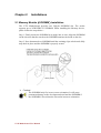
1
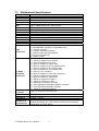
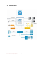
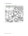
V270 Motherboard Mini-ITX Fan/Fanless SBC w/ VIA C7 NanoBGA2 processors, VGA, LCD, Giga Ethernet, Mini-PCI and PCMCIA Slot Interface. USER MANUAL Version 1.0 FCC Statement This device complies with part 15 FCC rules. Operation is subject to the following two conditions: This device may not cause harmful interference. This device must accept any interference received including interference that may cause undesired operation. This equipment has been tested and found to comply with the limits for a class "a" digital device, pursuant to part 15 of the FCC rules. These limits are designed to provide reasonable protection against harmful interference when the equipment is operated in a commercial environment. This equipment generates, uses, and can radiate radio frequency energy and, if not installed and used in accordance with the instruction manual, may cause harmful interference to radio communications. Operation of this equipment in a residential area is likely to cause harmful interference in which case the user will be required to correct the interference at him own expense. z z V270 Motherboard User Manual II Copyright Notice No part of this document may be reproduced, copied, translated, or transmitted in any form or by any means, electronic or mechanical, for any purpose, without the prior written permission of the original manufacturer. Trademark Acknowledgement Brand and product names are trademarks or registered trademarks of their respective owners. Disclaimer We reserves the right to make changes, without notice, to any product, including circuits and/or software described or contained in this manual in order to improve design and/or performance. We assume no responsibility or liability for the use of the described product(s), conveys no license or title under any patent, copyright, or masks work rights to these products, and makes no representations or warranties that these products are free from patent, copyright, or mask work right infringement, unless otherwise specified. Applications that are described in this manual are for illustration purposes only. We make no representation or warranty that such application will be suitable for the specified use without further testing or modification. Warranty Our warranty that each of its products will be free from material and workmanship defects for a period of one year from the invoice date. If the customer discovers a defect, we will, at its option, repair or replace the defective product at no charge to the customer, provided it is returned during the warranty period of one year, with transportation charges prepaid. The returned product must be properly packaged in it’s original packaging to obtain warranty service. If the serial number and the product shipping data differ by over 30 days, the in-warranty service will be made according to the shipping date. In the serial numbers the third and fourth two digits give the year of manufacture, and the fifth digit means the month (e. g., with A for October, B for November and C for December). For example, the serial number 1W08Axxxxxxxx means October of year 2008. V270 Motherboard User Manual III Packing List Before using this Motherboard, please make sure that all the items listed below are present in your package: ¾ V270 Motherboard ¾ V270 SBC User Manual ¾ HDD IDE Cable ¾ User’s Manual & Driver CD If any of these items are missing or damaged, contact your distributor or sales representative immediately. Customer Service We provide service guide for any problem as follow steps:First, visit the website of distributor to find the update information about the product. Second, contact with your distributor, sales representative, or our customer service center for technical support if you need additional assistance. You may have the following information ready before you call: ¾ Product serial number ¾ Peripheral attachments ¾ Software (OS, version, application software, etc.) ¾ Description of complete problem ¾ The exact wording of any error messages In addition, free technical support is available from our engineers every business day. We are always ready to give advice on application requirements or specific information on the installation and operation of any of our products. Please do not hesitate to call or e-mail us. V270 Motherboard User Manual IV Safety Precautions Warning! Always completely disconnect the power cord from your chassis whenever you work with the hardware. Do not make connections while the power is on. Sensitive electronic components can be damaged by sudden power surges. Only experienced electronic personnel should open the PC chassis. Caution! Always ground yourself to remove any static charge before touching the CPU card. Modern electronic devices are very sensitive to static electric charges. As a safety precaution, use a grounding wrist strap at all times. Place all electronic components in a static-dissipative surface or static-shielded bag when they are not in the chassis. 7 V270 Motherboard User Manual V Safety and Warranty 1. 2. 3. 4. 5. 6. 7. 8. 9. 10. 11. 12. 13. 14. 15. Please read these safety instructions carefully. Please keep this user's manual for later reference. Please disconnect this equipment from any AC outlet before cleaning. Do not use liquid or spray detergents for cleaning. Use a damp cloth. For pluggable equipment, the power outlet must be installed near the equipment and must be easily accessible. Keep this equipment away from humidity. Put this equipment on a reliable surface during installation. Dropping it or letting it fall could cause damage. The openings on the enclosure are for air convection. Protect the equipment from overheating. DO NOT COVER THE OPENINGS. Make sure the voltage of the power source is correct before connecting the equipment to the power outlet. Position the power cord so that people cannot step on it. Do not place anything over the power cord. All cautions and warnings on the equipment should be noted. If the equipment is not used for a long time, disconnect it from the power source to avoid damage by transient over-voltage. Never pour any liquid into an opening. This could cause fire or electrical shock. Never open the equipment. For safety reasons, only qualified service personnel should open the equipment. If any of the following situations arises, get the equipment checked by service personnel: A. The power cord or plug is damaged. B. Liquid has penetrated into the equipment. C. The equipment has been exposed to moisture. D. The equipment does not work well, or you cannot get it to work according to the user’s manual. E. The equipment has been dropped and damaged. F. The equipment has obvious signs of breakage. Do not leave this equipment in an uncontrolled environment where the storage temperature is below -20° C (-4°F) or above 60° C (140° F). It may damage the equipment. V270 Motherboard User Manual VI Revision History Version 1.0 Date 2008.07.15 9 V270 Motherboard User Manual Note First version VII Author Tim Lai Contents CHAPTER 1 1.1 1.2 1.3 1.4 1.5 CHAPTER 2 GENERAL INFORMATION.......................................1 INTRODUCTION ...............................................................................1 FEATURE .........................................................................................1 MOTHERBOARD SPECIFICATIONS ....................................................2 FUNCTION BLOCK ...........................................................................3 BOARD DIMENSIONS........................................................................4 INSTALLATIONS.........................................................6 2.1 MEMORY MODULE(SODIMM)INSTALLATION...........................6 2.2 2.3 2.4 2.5 I/O EQUIPMENT INSTALLATION .......................................................7 JUMPERS AND CONNECTORS ...........................................................8 JUMPER SETTING.............................................................................9 CONNECTORS AND PIN ASSIGNMENT ............................................12 CHAPTER 3 GRAPHIC DRIVER INSTALLATION ....................19 3.1 GRAPHIC DRIVER INSTALLATION.........................................................19 CHAPTER 4 CHIPSET DRIVER INSTALLATION .....................22 4.1 CHIPSET DRIVER INSTALLATION .......................................................22 CHAPTER 5 5.1 CHAPTER 6 ETHERNET DRIVER INSTALLATION..................27 INSTALLATION OF ETHERNET DRIVER ...........................................27 AUDIO DRIVER INSTALLATION..........................31 6.1 INTRODUCTION .................................................................................31 6.2 INSTALLATION OF AUDIO DRIVER .................................................31 CHAPTER 7 AMI BIOS INSTALLATION .........................................36 7.1 7.2 7.3 7.4 7.5 7.6 7.7 BIOS INTRODUCTION ...................................................................36 BIOS SETUP .................................................................................36 MAIN SETUP .................................................................................37 ADVANCED BIOS SETUP ...............................................................38 BOOT SETTING ..............................................................................42 SECURITY SETUP ...........................................................................44 SECURITY SETUP ...........................................................................46 V270 Motherboard User Manual VIII CHAPTER General Information 1 This chapter includes V270 Motherboard background information. Sections include: z Introduction z Feature z Motherboard Specification z Function Block z Board Dimensions V270 Motherboard User Manual 1 Chapter 1 1.1 General Information Introduction V270 SBC is equipped VIA VX700 All-in-One System Processor, is designed to enable high quality digital video streaming and DVD playback in a new generation of fanless, small form factor PCs and IA devices. The VX700 features the embedded VIA UniChrome™ Pro II 2D/3D MPEG-2, MPEG-4 and WMV9 video decoding acceleration, DDR2 533MHz support, dual-display support to ensure a rich overall entertainment experience. Outstanding connectivity features include USB 2.0, Giga LAN and ATA/133. In peripheral connectivity, V270 SBC with flexible I/O ports, as one PCMCIA slot, Mini-PCI, four serial ports, one PATA connector, one SATA II connector, and six Hi-Speed USB connectors. Thus, V270 SBC is designed to satisfy most of the applications in the industrial computer market, such as Gaming, POS, KIOSK, Industrial Automation, and Programmable Control System. It is a compact design to meet the demanding performance requirements of today’s business and industrial applications. 1.2 Feature ¾ ¾ ¾ ¾ ¾ ¾ ¾ ¾ ¾ ¾ Mini-ITX Form Factor ( 170mm x 170mm) Onboard VIA C7-M ULV/ C7-M NanoBGA2 processors, up to 1.6GHz 1 x DDR2 533 MHz SO-DIMM supporting up to 1GB Integrated VIA VX 700 Chipset VIA UniChrome Pro II AGP graphics with MPEG-2 / 4, WMV9 decoding acceleration Realtek RTL8110SC Gigabit Ethernet VT1708A High Definition Audio Controller, up to 8 high definition audio channels. 1 x PCMCIA slot, 1 x Mini PCI slot, 4 x COM, 6 x USB2.0, 1 x 40 pins IDE, 1 x SATA II, Graphic Output : 1 x VGA, 1 x S-Video(Optional), 1 x LVDS(or DVI) V270 Motherboard User Manual 1 1.3 Motherboard Specifications CPU Type CPU FSB CPU Socket Chipset BIOS VGA LVDS LAN Memory Type LPC I/O Keyboard/Mouse IDE Interface Sound USB Serial Edge Connectors On Board Pin-Header Connectors Power Connector Expansion Slots Form Factor Dimensions Mechanical & environmental Onboard VIA C7-M ULV/ C7-M NanoBGA2 processors, up to 1.6GHz 400 MHz / 800 MHz Onboard VIA NanoBGA2 package VIA VX 700 AMI 8Mbit Flash VIA VX 700 integrated VIA UniChrome™ Pro II Graphics Engine Up to 128MB shared with system memory Built in single- or Dual-channel LVDS, support up to 1600 x 1200, 24bit 1 x Giga LAN (Realtek RTL8110SC Controller ) 1 x DDR2 SODIMM socket, supports up to 1GB DDR2 533 SDRAM Winbond W83627EHG integrated hardware monitoring 1 x Mini-DIN connector supports PS/2 Keyboard/Mouse connectors Dual channels; supports Ultra DMA 33/66/100 VIA VT1708A (Line-in, Line-out, Mic in) 6 ports, USB 2.0 (2 x USB Connector, 4 x USB pin-header ) 4 serial ports(1 x RS-232/422/485 Connector, 3 x RS-232 pin-header) 1 x 12V DC-IN Jack 1 x Mini-DIN PS/2 connector for keyboard/mouse 1 x VGA out connector 1 x S-Video Connector (Optional) 1 x DB9 for COM1 (RS-232/422/485) 1 x RJ-45 for Gigabit LAN 2 x USB 2.0 ports 1 x 40 pins box-header 1 x 10pins pin-header for Front Panel 1 x 3pins pin-header for CPU Fan 1 x 3pins pin-header for System FAN 1 x 8pins pin-header for 5V/12V external power 1 x 2pins pin-header for 5V external power 1 x 2pins pin-header for 12V external power 1 x 4pins ATX 12V connector 2 x 2pins pin-header for Front Audio (with Amp.) 1 x 12pins pin-header for Front Audio 2 x 8pins pin-header for USB 3/4/5/6 1 x 20pins pin-header for COM 2/3 1 x 10pins pin-header for COM 4 1 x 40pins DF13 Connector for LVDS 1 x 3pins digital panel backlight brightness controller 1 x 7pins digital panel backlight controller 1 x 10pins pin-header for Digital IO Input: Din-4Pin DC 12V Power input 1 x PCMCIA type II, 1 x Mini-PCI Mini-ITX 170mm x 170mm Operating temperature: 0 deg. C to 60 deg. C Operating Humidity: 30 ~ 90% Relative humidity, non-condensing Certification: CE, FCC, RoHS V270 Motherboard User Manual 2 1.4 Function Block V270 Motherboard User Manual 3 1.5 Board dimensions V270 Motherboard User Manual 4 CHAPTER Installations 2 This chapter provides information on how to use the jumps and connectors on V270Motherboard. The Sections include: z Memory Module Installation z I / O Equipment Installation z Setting the Jumpers z Connectors on V270Motherboard V270 Motherboard User Manual 5 Chapter 2 Installations 2.1 Memory Module(SODIMM)Installation The V270 Motherboard provides one 200-pin SODIMM slot. The socket supports up to 2GB DDR2 533 SDRAM. When installing the Memory device, please follow the steps below: Step.1. Firmly inserts the SODIMM at an angle into its slot. Align the SODIMM on the slot such that the notch on the SODIMM matches the break on the slot. Step.2. Press downwards on SODIMM until the retaining clips at both ends fully snap back in place and the SODIMM is properly seated. ¾ Caution! The SODIMM only fits in one correct orientation. It will cause permanent damage to the development board and the SODIMM if the SODIMM is forced into the slot at the incorrect orientation. V270 Motherboard User Manual 6 2.2 I/O Equipment Installation 2.2.1 12V DC-IN The Motherboard allows plugging 12V DC-IN jack on the board without another power module converter under power consumption by VIA C7-M NanoBGA2 processor in VX700 chipset. 2.2.2 PS/2 Keyboard and PS/2 Mouse The Motherboard provides one Mini-DIN connector supports PS/2 interface. Mini-DIN connector supports Keyboard or Mouse. In other cases, especially in embedded applications, a mouse is not used. Therefore, the BIOS standard setup menu allows you to select* “All, But Keyboard” under the “Halt On”. This allows no-keyboard operation in embedded system applications without the system halting under POST. 2.2.3 Serial COM ports One serial connector build in the rear I/O supports RS232/422/485 selection through jumper setting and three internal RS-232 ports pin-header. When an optional touch-screen is ordered with PPC, serial com port can connect to a serial or an optional touch-screen. 2.2.4 Internal VGA The Motherboard has one VGA port that can be connected to an external CRT/ LCD monitor. Use VGA cable to connect to an external CRT / LCD monitor, and connect the power cable to the outlet. The VGA connector is a standard 15-pin D-SUB connector. 2.2.5 Ethernet interface The Motherboard is equipped with one Realtek RTL8110SC chipsets which is fully compliant with the PCI 10/100/1000 Mbps Ethernet protocol compatible. It is supported by major network operating systems. The Ethernet ports provide one standard RJ-45 jacks. 2.2.6 USB ports Six USB devices (four with pin headers) may be connected to the system though an adapter cable. Various adapters may come with USB ports. USB usually connect the external system to the system. The USB ports support hot plug-in connection. Whatever, you should install the device driver before you use the device. 2.2.7 Audio Jack ( Pin-header) The Audio 7.1 channel capabilities are provided by a VIA VT1708A chipset supporting digital audio outputs. The audio interface includes Mic-in, line-in and line-out. V270 Motherboard User Manual 7 2.3 Jumpers and Connectors TOP J1 JP1 FAN 1 CON 1 SATA 1 J7 FAN 2 IDE 1 J2 J3 FAN 2 J4 CON 2 / CON 3 Panel 1 J5 USB 1 / USB 2 CN2 J6 CN4 Mini PCI BOTTOM JP2 J7 J8 J9 J10 CON 5 DC Jack PS/2 VGA V270 Motherboard User Manual S-Video (Optional) 8 COM RJ-45 USB 2.4 Jumper Setting A pair of needle-nose pliers may be helpful when working with jumpers. If you have any doubts about the best hardware configuration for your application, contact your local distributor or sales representative before you make any changes. Generally, you simply need a standard cable to make most connections. The jumper setting diagram is as below. If a jumper shorts pin 1 and pin 2, the setting diagram is shown as the right one. 1 2 3 The following tables list the function of each of the board's jumpers. Label Function Note JP1 Clear CMOS 3x1 header , pitch 2.0mm JP2 LVDS / DVI Selector 3x1 header , pitch 2.0mm J2 RS232 / RS422 / RS485 Selector 3x4 header , pitch 2.0mm J3 RS232 / RS422 / RS485 Selector 3x2 header , pitch 2.0mm CN2 Panel Voltage Selector 2x3 header , pitch 2.0mm V270 Motherboard User Manual 9 2.4.1 JP1: Clear CMOS User must make sure the power supply to turn off the power supply before setting Clear CMOS. Users remember to setting jumper back to Normal before turning on the power supply. Default: 2 short 3. Clear CMOS 2.4.2 Normal 1 1 2 2 3 3 DVI 1 1 2 2 3 3 Pin No. 1 Short 2 2 Short 3 Functions LVDS DVI J2: RS232 / RS422 / RS485 Selector The jumper can be configured to operate COM1 in RS-232/422/485 mode. And the setting must be cooperated with J3 settings. RS232 RS422/485 1 3 1 3 4 6 4 6 7 9 7 9 10 2.4.4 Functions Clear CMOS Normal JP2: LVDS / DVI Selector The jumper can select CN4 connector providing LVDS or DVI signal. Default: 1 short 2. LVDS 2.4.3 Pin No. 1 Short 2 2 Short 3 12 10 RS232 1-2 4-5 7-8 10-11 12 RS422/485 2-3 5-6 8-9 11-12 J3: COM1 RS232 / RS422 / RS485 Function Selector The jumper can be configured to operate COM1 in RS-232/422/485 mode. And the setting must be cooperated with the 2.4.3 settings. Default 1 short 2. RS232 RS422 RS485 1 2 1 2 1 2 3 4 3 4 3 4 5 6 5 6 5 6 V270 Motherboard User Manual Pin No. 1 Short 2 3 Short 4 5 Short 6 10 Functions RS232 RS422 RS485 2.4.5 CN2: Panel Voltage Select CN2 can be configured to operate in 3.3Volts / 5Volts / 12Volts mode. 3.3Volts 5Volts 12Volts 1 2 1 2 1 2 3 4 3 4 3 4 5 6 5 6 5 6 V270 Motherboard User Manual Pin No. 1 Short 2 3 Short 4 5 Short 6 11 Functions 3.3Volts Selected 5Volts Selected 12Volts Selected 2.5 Connectors and Pin Assignment The table below lists the function of each of the board’s connectors. Rear I/O connectors: Label Function Note CON6 12V DC Jack 4x1 Pin Jack PSKBM1 PS2 Keyboard/Mouse Connector PS/2 Conn. CN8 VGA Output Connector D-sub 15pin VGA CN6 S-Video CN7 RS-232/422/485 Connector D-sub 9pin COM LAN1 RJ-45 Connector RJ-45 Giga LAN J11 Dual USB Connector USB 2.0 Internal I/O Pin-headers: Label Function Note CN4 LVDS LCD Output Connector DF13-40DP-1.25V J7 Backlight Brightness Control 3x1 header, pitch 2.54mm J6 Inverter Connecter 7x1 header, pitch 2.54mm J4 COM2/COM3 Serial Port 2x10 header, pitch 2.0mm J5 COM4 Serial Port 2x5 header, pitch 2.0mm IDE2 IDE Connector 40Pin IDE Conn. SATA1 SATA Connector SATA Conn. USB1 USB 3/USB 4 4x2 header, pitch 2.0 mm USB2 USB 5/USB 6 4x2 header, pitch 2.0 mm FAN1 FAN Connector 3x1 header, pitch 2.54mm FAN1 FAN Connector 1x3 header, pitch 2.54mm PANEL1 System Function Connector 2x5 header ,pitch 2.0mm J8 Front Audio (Right) 1x2 header ,pitch 2.54mm J9 Front Audio (Left) 1x2 header ,pitch 2.54mm CON2 12V External Power 2x1 header, pitch 2.54mm CON3 5V External Power 2x1 header, pitch 2.54mm CON1 5V/12V External Power 4x2 header ,pitch 2.54mm J10 Audio Function Connector 6x2 header ,pitch 2.0mm CON4 Digital I/O 2x5 header ,pitch 2.0mm CON5 12V DC Jack 4 Pin Jack V270 Motherboard User Manual 12 2.5.1 CN4: LVDS Connector Pin No. 1 3 5 7 9 11 13 15 17 19 21 23 25 27 29 31 33 35 37 39 2.5.2 SYMBOL LCDVDD LCDVDD LCDVDD GND GND GND GND GND GND GND GND GND GND GND GND GND GND GND GND GND Pin No. 2 4 6 8 10 12 14 16 18 20 22 24 26 28 30 32 34 36 38 40 SYMBOL LVDS_LTX0LVDS_LTX0+ LVDS_LTX1LVDS_LTX1+ LVDS_LTX2LVDS_LTX2+ LVDS_LCLKLCDS_LCLK NC NC LVDS_UTX0LVDS_UTX0+ LVDS_UTX1LVDS_UTX1+ LVDS_UTX2LVDS_UTX2+ LVDS_UCLKLVDS_UCLK NC NC J7: Digital Panel Backlight Brightness Control Pin No. 1 2 3 V270 Motherboard User Manual SYMBOL VCC Black Light Control GND 13 2.5.3 J6: Inverter Power connector Pin No. 1 2 3 4 5 6 7 SYMBOL +12V +12V +12V GND Black Light Control GND Black Light EN 5V 2.5.4 J4: COM2/COM3 serial Ports The J4 serial port, which provides dual RS-232 function. Pin No. SYMBOL 20 GND Pin No. SYMBOL 19 GND 18 FK NRI2 17 FK NDTR2 16 FK NCTS2 15 FK NSOUT2 14 FK NRTS2 13 FK NSIN2 12 FK NDSR2 11 FK NDCD2 10 GND 9 GND 8 FK NRI1 7 FK NDTR1 6 FK NCTS1 5 FK NSOUT1 4 FK NRTS1 3 FK NSIN1 2 FK NDSR1 1 FK NDCD1 V270 Motherboard User Manual 14 2.5.5 J5: COM4 Serial port The J5 serial port, which provides one RS-232 function. 2 4 6 8 10 2.5.6 1 3 5 7 9 Pin 2 4 6 8 10 SYMBOL NDSR1A NRTS1A NCTS1A NRI1A GND Pin 1 3 5 7 9 SYMBOL NDCD1A NRXD1A NTXD1A NDTR1A GND IDE1: 40 pins IDE Connector Signal Name Reset IDE Host data 7 Host data 6 Host data 5 Host data 4 Host data 3 Host data 2 Host data 1 Host data 0 Ground DRQ0 Host IOW Host IOR IOCHRDY DACK0 IRQ14 Address 1 Address 0 Chip select 0 Activity V270 Motherboard User Manual Pin # 1 3 5 7 9 11 13 15 17 19 21 23 25 27 29 31 33 35 37 39 Pin # 2 4 6 8 10 12 14 16 18 20 22 24 26 28 30 32 34 36 38 40 15 Signal Name Ground Host data 8 Host data 9 Host data 10 Host data 11 Host data 12 Host data 13 Host data 14 Host data 15 Protect pin Ground Ground Ground Host ALE Ground No connect No connect Address 2 Chip select 1 Ground 2.5.7 USB1 / USB2: USB PIN HEADER 2 2.5.8 1 4 3 6 5 8 7 Pin 2 4 6 8 USB1 / USB2 SYMBOL Pin USBVCC 1 USB_P63 USB_P6+ 5 GND 7 FAN1/ FAN2: FAN CONNECTOR FAN1 2.5.9 2 4 6 8 10 SYMBOL USBVCC USB_P7USB_P7+ GND FAN2 PANEL1: Front Panel System Function Connector Pin 2 4 6 8 10 1 3 5 7 9 SYMBOL HD_LED+ HD_LEDRT_BT1 RT_BT2 5VSB Pin 1 3 5 7 9 2.5.10 J8/J9: Front Audio J8 V270 Motherboard User Manual J9 16 SYMBOL PW_LED+ PW_LEDPW_BT1 PW_BT2 RSEV 2.5.11 CON2/CON3/CON1: External Power CON2 CON3 CON1 2.5.12 J10: Audio Connector 2 1 12 11 Pin SYMBOL Pin SYMBOL 2 4 6 8 10 12 GND GND Mic in Sensor Line in Sensor Line out Sensor Line in L 1 3 5 7 9 11 Mic in L Mic in R Line out R Front IO Sensor Line out L Line in R 2.5.13 CON4: Digital: Digital I/O Connector 2 4 6 8 10 1 3 5 7 9 Pin 2 4 6 8 10 SYMBOL Vcc Out1 Out0 IN1 IN0 Pin 1 3 5 7 9 2.5.14 ATX12V1: 12V DC Connector Pin 1 2 3 4 V270 Motherboard User Manual SYMBOL Ground Ground +12V +12V 17 SYMBOL GND Out3 Out2 IN3 IN2 CHAPTER 3 Graphic Driver Installation This chapter offers information on the chipset software Installation utility z z Installation of Graphic Driver Panel Resolution Setting V270 Motherboard User Manual 18 Chapter 3 Graphic Driver Installation 3.1 Graphic Driver Installation V270 Motherboard is equipped with VIA VX 700 integrated VIA UniChrome™ Pro II Graphics Engine. The VIA Graphic Drivers should be installed first, and it will enable “Video Controller (VGA compatible). Follow the instructions below to complete the installation. You will quickly complete the installation. Step.1. Insert the CD that comes with the Motherboard. Open the file document “Graphic_VX700_Driver “. Step.2. Click on “Setup.exe” to execute the setup. V270 Motherboard User Manual 19 Step.3. It will be auto-install Graphic Driver. Step.4. Click on “Finish“ to install Driver. V270 Motherboard User Manual 20 CHAPTER 4 Chipset Driver Installation This chapter offers information on the chipset software Installation utility z z Installation of Chipset Driver Further information V270 Motherboard User Manual 21 Chapter 4 4.1 Chipset Driver Installation Chipset Driver Installation Setp.1. Insert the CD that comes with the motherboard. Open the file document “Chipset_VX700_Driver”. Setp.2. Click on “Setup“ to install driver. V270 Motherboard User Manual 22 Setp.3. Click on “Next“ to install driver. V270 Motherboard User Manual 23 Setp.4. Click on “Next“ to install driver. Setp.5. Click on “Next“ to install driver. V270 Motherboard User Manual 24 Step.6. Click on “Yes, I want to restart this computer now“ to go on. V270 Motherboard User Manual 25 CHAPTER 5 Ethernet Driver Installation This chapter offers information on the Ethernet software installation utility. Sections include: z Introduction z Installation of Ethernet Driver V270 Motherboard User Manual 26 Chapter 5 Ethernet Driver Installation 5.1 Installation of Ethernet Driver The Users must make sure which operating system you are using in the V270Motherboard before installing the Ethernet drivers. Follow the steps below to complete the installation of the Realtek RTL8110SC LAN drivers. You will quickly complete the installation. Step.1. Insert the CD that comes with the motherboard. Open the file document “LAN Driver”. Step.2 Click on “Setup” to execute the setup. V270 Motherboard User Manual 27 Step.3. Click on “Next“ to install driver. Step.3. Click on “Install“ to install driver. V270 Motherboard User Manual 28 Setp.3. Click on “Finish“ and go on. V270 Motherboard User Manual 29 CHAPTER 6 Audio Driver Installation This chapter offers information on the Audio software installation utility. Sections include: z Introduction z Installation of Audio Driver V270 Motherboard User Manual 30 Chapter 6 6.1 Audio Driver Installation Introduction The V270Motherboard is equipped with the VIA Vinyl VT1708 chipset. The VIA VT1708 series deliver top quality audio performance, supporting the latest 8-channel, 24-bit, 192KHz audio content for an all-round high fidelity experience. 6.2 Installation of Audio Driver The users must make sure which operating system you are using in the V270 Motherboard before installing the Audio drivers. Follow the steps below to complete the installation of the VIA Vinyl VT1708 Audio drivers. You will quickly complete the installation. Step.1. Insert the CD that comes with the motherboard. Open the file document “Audio_VT708A_Driver” to execute the setup. V270 Motherboard User Manual 31 Step.2. Click on “Setup” to execute the setup V270 Motherboard User Manual 32 Step.3. Click on “Next“ to install driver. Step.4. Click on “Next“ to install driver. V270 Motherboard User Manual 33 Step.5. Click on “Next“ to install driver. Step.6. Click on “Yes, I want to restart this computer now“ to go on. V270 Motherboard User Manual 34 CHAPTER 7 AMI BIOS Installation This chapter describes the different settings available in the AMI BIOS that comes with the board. This chapter offers information on the AMI BIOS installation utility. Sections include: z z z z z z z z z z z z z BIOS Introduction BIOS Setup Standard CMOS Setup Advanced BIOS Features Advanced Chipset Features Integrated Peripherals Power Management Setup PC Health Status Load Fail-Safe Defaults Load Optimized Defaults Set Supervisor/User Password Save & Exit Setup Exit Without Saving V270 Motherboard User Manual 35 Chapter 7 AMI BIOS Installation 7.1 BIOS Introduction AMI BIOS (Basic Input/Output System) installed in your computer system’s ROM supports Intel processors. The BIOS provides critical low-level support for a standard device such as disk drives, serial ports and parallel ports. It also adds virus and password protection as well as special support for detailed fine-tuning of the chipset controlling the entire system. 7.2 BIOS Setup The Main BIOS setup menu screen has two main frames. The left frame displays all the options that can be configured. “Grayed-out” options cannot be configured. Options is blue can be. The right frame displays the key legend. Above the key legend is an area reserved for a text message. When an option is selected in the left frame, it is highlighted in white. Often a text message will accompany it. The BIOS setup/utility uses a key-based navigation system called hot keys. Most of the BIOS setup utility hot keys can be used at any time during the setup navigation process. These keys include <F1>, <F10>, <Enter>, <ESC>, <Arrow> keys, and so on. V270 Motherboard User Manual 36 7.3 Main Setup When you first enter the Setup Utility, you will enter the Main setup screen. You can always return to the Main setup screen by selecting the Main tab. There are two Main Setup options. They are described in this section. The Main BIOS Setup screen is shown below. 9 System Time/System Date Use this option to change the system time and date. Highlight System Time or System Date using the <Arrow> keys. Enter new values through the keyboard. Press the <Tab> key or the <Arrow> keys to move between fields. The date must be entered in MM/DD/YY format. The time is entered in HH:MM:SS format. Note: The time is in 24-hour format. For example, 5:30 A.M. appears as 05:30:00, and 5:30 P.M. as 17:30:00. V270 Motherboard User Manual 37 7.4 Advanced BIOS Setup Select the Advanced tab from the setup screen to enter the Advanced BIOS Setup screen. You can select any of the items in the left frame of the screen, such as CPU Configuration, to go to the sub menu for that item. You can display an Advanced BIOS Setup option by highlighting it using the <Arrow> keys. All Advanced BIOS Setup options are described in this section. The Advanced BIOS Setup screen is shown below. The sub menus are described on the following pages. 9 CPU Configuration You can use this screen to show the information for processor detail specifications. An example of the CPU Configuration screen is shown below. V270 Motherboard User Manual 38 9 IDE Configuration Settings You can use this screen to select options for the IDE Configuration Settings. Use the up and down <Arrow> keys to select an item. Use the <Plus> and <Minus> keys to change the value of the selected option. A description of the selected item appears on the right side of the screen. The settings are described on the following pages. An example of the IDE Configuration screen is shown below. SATA Device, IDE Master, IDE Slave Select one of the hard disk drives to configure it. Press <Enter> to access its’ the sub menu. The options on the sub menu are described in the following sections. V270 Motherboard User Manual 39 9 APM Configuration You can use this screen to select options for the ACPI Advanced Configuration Settings. Use the up and down <Arrow> keys to select an item. Use the <Plus> and <Minus> keys to change the value of the selected option. A description of the selected item appears on the right side of the screen. The settings are described on this page. The screen is shown below. ACPI Version Features Set this value to allow or prevent the system to be complaint with the ACPI 3.0 specification. ACPI APIC support APIC stands for Advanced Programmable Interrupt Controller. The default setting is Enabled. AMI OEMB table Set this value to allow the ACPI BIOS to add a pointer to an OEMB table in the Root System Description Table (RSDT) table. The default setting is Enabled. Headless mode This option is used to update the ACPI FACP table to indicate headless operations. The default setting is Disabled. V270 Motherboard User Manual 40 9 APM Configuration Set this value to allow Power Management/APM support. The Optimal and Fail-Safe default setting is Enabled. Power Button Mode This option specifies how the externally mounted power button on the front of the computer chassis is used. The default setting is On/Off. Suspend Power Saving Type Set this value to allow the Suspend Power Saving type to be specified. The default setting is C3. Restore on AC/Power Loss Set the system status after AC power loss. The default setting is Power on. Option Power Off Keep Current Last State Description System always Powers Off System always Powers On System returns to the last state before AC power loss V270 Motherboard User Manual 41 7.5 Boot Setting 9 Boot Device Priority Use this screen to specify the order in which the system checks for the device to boot from. To access this screen, select Boot Device Priority on the Boot Setup screen and press <Enter>. The following screen displays: 1st Boot Device Set the boot device options to determine the sequence in which the computer checks which device to boot from. The settings are Removable Dev., Hard Drive, or USB-CDROM. V270 Motherboard User Manual 42 To change the boot order, select a boot category type such as Hard disk drives, USB devices, or SATA devices from the boot menu. For example, if the 1st boot device is set to SATA devices, then BIOS will try to boot to SATA devices first. Note: When you select a boot category from the boot menu, a list of devices in that category appears. For example, if the system has three hard disk drives connected, then the list will show all three hard disk drives attached. V270 Motherboard User Manual 43 7.6 Security Setup Two Levels of Password Protection provides both a Supervisor and a User password. If you use both passwords, the Supervisor password must be set first. The system can be configured so that all users must enter a password every time the system boots or when Setup is executed, using either or either the Supervisor password or User password. The Supervisor and User passwords activate two different levels of password security. If you select password support, you are prompted for a one to six character password. Type the password on the keyboard. The password does not appear on the screen when typed. Make sure you write it down. If you forget it, you must drain NVRAM and reconfigure. Select Security Setup from the Setup main BIOS setup menu. All Security Setup options, such as password protection and virus protection, are described in this section. To access the sub menu for the following items, select the item and press <Enter>: Change Supervisor Password Change User Password Clear User Password V270 Motherboard User Manual 44 The Security Setup screen is shown below. The sub menus are documented on the following pages. Supervisor Password Indicates whether a supervisor password has been set. If the password has been installed, Installed displays. If not, Not Installed displays. User Password Indicates whether a user password has been set. If the password has been installed, Installed displays. If not, Not Installed displays. Change Supervisor Password Select this option and press <Enter> to access the sub menu. You can use the sub menu to change the supervisor password. Change User Password Select this option and press <Enter> to access the sub menu. You can use the sub menu to change the user password. Clear User Password Select this option and press <Enter> to access the sub menu. You can use the sub menu to clear the user password. V270 Motherboard User Manual 45 7.7 Security Setup Select the Exit tab from the setup screen to enter the Exit BIOS Setup screen. You can display an Exit BIOS Setup option by highlighting it using the <Arrow> keys. All Exit BIOS Setup options are described in this section. The Exit BIOS Setup screen is shown below. Saving Changes and Exit When you have completed the system configuration changes, select this option to leave Setup and reboot the computer so the new system configuration parameters can take effect. Select Exit Saving Changes from the Exit menu and press <Enter>. Save Configuration Changes and Exit Now? [Ok] [Cancel] appears in the window. Select Ok to save changes and exit. Discarding Changes and Exit Select this option to quit Setup without making any permanent changes to the system configuration. Select Exit Discarding Changes from the Exit menu and press <Enter>. Discard Changes and Exit Setup Now? [Ok] [Cancel] appears in the window. Select Ok to discard changes and exit. Discard Changes Select Discard Changes from the Exit menu and press <Enter>. V270 Motherboard User Manual 46 Load Optimal Defaults Automatically sets all Setup options to a complete set of default settings when you select this option. The Optimal settings are designed for maximum system performance, but may not work best for all computer applications. In particular, do not use the Optimal Setup options if your computer is experiencing system configuration problems. Select Load Optimal Defaults from the Exit menu and press <Enter>. V270 Motherboard User Manual 47