1
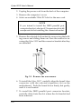
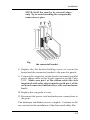
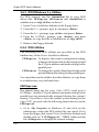
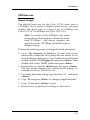
Installation
Chapter 2
Installation
This chapter will guide you through the installation of your
Cyber 2S1P. There are no jumpers or switches to set for this
PCI Plug-n-Play board.
2-1 Installing the Cyber 2S1P
Proceed with the following instructions to install the card in
your computer. General installation instructions are given
since the design of computer cases varies. Refer to your
computer’s reference manual whenever in doubt.
NOTE: Leave the Cyber 2S1P board in its staticresistant bag until you are ready to install it.
1. Turn OFF the power to your computer and any other
connected peripheral devices. Follow the precautions for
static electricity discharge.
CAUTION: STATIC ELECTRICITY DISCHARGE
may permanently damage your system. In order to
avoid possible static electricity discharge during
installation procedures, please follow the guidelines
below:
• Discharge any static electricity build up in your body by
touching a large grounded metal surface such as the
computer case (if plugged in), a metal window frame,
refrigerator, or water tap for a few seconds.
• During installation procedures, avoid any contact with
internal parts. Handle cards only by their edges.
CAUTION: Disconnect the AC power source
before removing the cover.
2-1
Cyber 2S1P User's Manual
2. Unplug the power cord from the back of the computer.
3. Remove the computer’s cover.
4. Select an available 32-bit PCI slot for the new card.
NOTE
If you intend to install the DB25 parallel port
connector bracket, select an I/O expansion slot with
an adjacent slot for installing the connector bracket.
5. Remove the selected slot brackets by unscrewing the holding screws and sliding them out. Save the screws for securing the Cyber 2S1P and the connector bracket after they
are installed.
Fig. 2-1. Remove the Slot Bracket
6. To install the Cyber 2S1P, carefully align the board’s bus
connector with the selected expansion slot on the
motherboard. Push the board down firmly, but gently,
until it is well seated.
7. To install the DB25 parallel port connector bracket,
carefully slide it into the slot where the slot bracket had
been removed.
2-2
Installation
NOTE: Hold the card by its external edges
only. Try to avoid touching the components,
connectors or pins.
Fig. 2-2. Install the Cyber 2S1P and
the connector bracket
8. Replace the slot bracket holding screws to secure the
board and the connector bracket to the rear slot panels.
9. Connect the connector on the bracket mounted parallel
port's ribbon cable to the 26-pin connector on the Cyber
2S1P. Make sure pin 1 of the ribbon cable (the side
imprinted with color stripe) matches with pin 1 of the
on-board connector (indicated by a silk screened number 1).
10. Replace the computer's cover.
11. Reconnect the power cord and make new connections to
the ports.
The hardware installation is now complete. Continue to the
next section for the installation of the driver and utility files.
2-3
Cyber 2S1P User's Manual
2-2 Installing the Drivers and Utilities
This section provides information on how to install the
Cyber 2S1P's drivers and utilities for the following
operating systems:
Windows 95/98
Windows NT 4.0
DOS/Windows 3.x
IMPORTANT
Make sure you have installed the Cyber 2S1P
in your system BEFORE installing the software.
2-2.1 Windows 95 & 98 Driver Installation
Perform the following steps to install the drivers for
Windows 95/98:
1.
When you first turn on your computer after installing the
Cyber 2S1P, Windows will notify you of “New Hardware
Found”. From the choices listed on the screen, select:
“• Driver from disk provided by hardware manufacturer”
and click OK.
2.
Insert the Driver Installation diskette in the floppy drive
and click OK.
3.
Make sure the path in the command line window is
A:\. Then, click on OK to install the driver files.
4.
Remove the diskette and select Yes to restart your
computer to finish setting up the new hardware.
To verify successful installation:
1. From the main desktop, click on My Computer, then doubleclick on Control Panel, System, and Device Manager.
2. Double-click on SIIG Cyber PCI device options. SIIG
Cyber 2S1P Board should be displayed when successfully
installed. The port is ready to connect your new device.
2-4
Installation
2-2.2 Windows NT 4.0 Driver Installation
The Windows NT 4.0 drivers and associated files reside in
the NT subdirectory on the Driver Installation diskette.
Perform the following steps to install the Windows NT 4.0
drivers.
1
Boot up from Microsoft Windows NT 4.0.
2.
Insert the Driver Installation diskette in the floppy drive.
3.
From the desktop, double-click on My Computer, then
3 1/2 Floppy (A:) and NT subdirectory.
4.
Double-click on the setup icon. When the program
opens to the “SIIG Cyber PCI Welcome” window, click on
Next to continue.
5.
From the “Choose Destination Location” window, click
Next to install the driver files in the default folder. Or
click Browse to change, then click Next to proceed.
6.
From the next “Setup Complete” window, click Finish.
7.
Remove the diskette and click on Finish to reboot your
system.
To verify successful installation:
1.
From the main desktop, click on My Computer, then
Control Panel.
2.
Double-click on the SIIG Cyber PCI icon. The assigned
system configuration will be displayed.
Note: During system startup after installing the
board, a non-conflicting system setting such as
COM port and base I/O address will be assigned.
If you like to change it to a specific setting, you can
override the assigned setting by going into the
Control Panel, SIIG Cyber PCI, Settings, then
Advanced to change it.
2-5
Cyber 2S1P User's Manual
2-2.3 DOS/Windows 3.x Utilities
For DOS support, run the dosinst.bat file to copy DOS
driver files cb10xpc.exe, cb10xsu.exe and dosinst.bat to
subdirectory c:\siig\cb10x> on drive C.
1. Insert Driver Installation diskette in the floppy drive.
2. From the C:\> prompt, type a: and press <Enter>.
3. From the A:\> prompt, type cd dos and press <Enter>.
4. From the A:\DOS> prompt, type dosinst and press
<Enter> to copy the files to subdirectory c:\siig\cb10x.
5. Remove the floppy diskette.
2-2.4 DOS Utilities
The following two DOS utilities are provided in the DOS
subdirectory of the Driver Installation diskette:
CB10xpc.exe To display the current configuration setting
of the speed of baud rate for the serial port and
the I/O port address and mode setting for the
parallel port.
CB10xsu.exe To change the speed of baud rate for the serial
port and the mode setting for the parallel port.
You can either run the utilities from the diskette, or copy them
to a subdirectory on your hard drive.
CB10xpc.exe
The default baud rate for your Cyber 2S1P's serial port is
115.2Kbps. And the I/O port address and mode setting for the
parallel port are automatically assigned during the system's
startup. If you like to view the current system setting for the
Cyber 2S1P, proceed with the following instruction to run the
CB10xpc.exe:
• Go to My Computer in Windows 95 and click on the
subdirectory where the DOS utility files are stored. If it is
from the floppy disk, insert Driver Installation diskette and
double-click on “3 1/2 Floppy (A:)”, “DOS” folder and the
file cb10xpc.exe to display the current settings.
2-6
Installation
CB10xsu.exe
Speed Change
The default baud rate for the Cyber 2S1P's serial port is
115.2Kbps. If you connect a higher speed device, you may
change the baud rate to support up to 460Kbps for
Cyber 2S1P PCI or 920Kbps for Cyber 2S1P Plus.
Note: To switch to 460/920Kbps only when
using a device that supports a baud rate faster
than 115.2Kbps. Any device supports the
speed less than 115.2Kbps should be kept at
default setting.
Perform the following steps to change the baud rate speed:
1. Go to My Computer in Windows 95 and click on the
subdirectory where the DOS utility files are stored. If it is
from the floppy disk, insert Driver Installation diskette and
double-click on “3 1/2 Floppy (A:)”and press <Enter>. Then
double-click on the “DOS” folder and press <Enter>.
2. Double-click on the file cb10xsu.exe and press <Enter>.
The first screen displays the current mode setting, for
example: Serial port, Baud Rate=Low
3. To change the mode setting, type the letter “C” and press
<Enter>.
4. Type "H" and press <Enter> to change to high baud rate.
5. Type "Q" and press <Enter> to quit.
6. Restart your system for the change to take effect.
2-7
Cyber 2S1P User's Manual
Mode Change
Your Cyber 2S1P supports EPP/ECP, ECP, EPP, and
BPP/SPP modes. The default mode setting is EPP/ECP.
You can change the mode by running cb10xsu.exe.
1. Go to My Computer in Windows 95 and click on the
subdirectory where the DOS utility files are stored. If it is
from the floppy disk, insert Driver Installation diskette and
double-click on “3 1/2 Floppy (A:)”and press <Enter>. Then
double-click on the “DOS” folder and press <Enter>.
2. Double-click on the file cb10xsu.exe and press <Enter>.
The first screen displays the current mode setting, for
example: Parallel 1, EPP(1.9)/ECP.
3. To change the mode setting, type the letter “C” and press
<Enter>.
4. Type in the number corresponding to the mode you want to
change to, such as “4” for BPP/SPP and press <Enter>. The
screen will display the change.
5. Type “Q” and press <Enter> to quit.
6. Restart your system for the change to take effect.
2-8