1
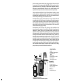
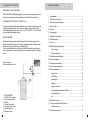
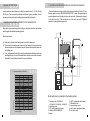
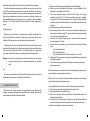
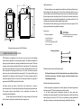
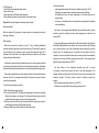
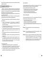
®
®
e-mail: [email protected]
www.eko-vimar.com.pl
tel.: +48 77/ 400 55 80÷81, 400 55 91
fax: +48 77/ 439 05 03, 400 55 96
EKO-VIMAR ORLAÑSKI ul. Nyska 17b
48-385 Otmuchów / woj. opolskie
POLSKA
Boiler connected in cascade enables heating of bigger buildings. Boilers should be of
the same output. Such system gives better possibilities of heat source dynamics than
system with one boiler only. Particularly in .transition period. (springtime or autumn)
boilers may be serviced alternately. Boilers with such connection enables for its
exploitation with the output close to nominal, what warrants boiler longer durability.
Heat accumulation tanks allows for boilers' better adjustment according to actual
weather conditions. In transition period (the spring, autumn) any boiler without heat
accumulation set is switched on and off very often. If the set is connected, the boiler
works constantly and the energy is cumulated into the vessels.
Each boiler switching on and off means fuel losses. It may be avoided if the heat
accumulation set is used. Simultaneously, in transition period (the lowest temperature
in winter time) the accumulation set helps to reheat the whole central heating system.
Also it should be mentioned that few heat sources such as solar collector , heating
pump or similar may be connected to the heat accumulation set.Boiler connected in
cascade enables heating of bigger buildings.
Boilers should be of the same output. Such system gives better possibilities of heat
source dynamics than system with one boiler only. Particularly in .transition period.
(springtime or autumn) boilers may be serviced alternately. Boilers with such
connection enables for its exploitation with the output close to nominal, what warrants
boiler longer durability. Heat accumulation tanks allows for boilers' better adjustment
according to actual weather conditions. In transition period (the spring, autumn) any
boiler without heat accumulationset is switched on and off very often. If the set is
connected, the boiler works constantly and the energy is cumulated into the vessels.
Each boiler switching onand off means fuel losses. It may be avoided if the heat
accumulation set is used. Simultaneously, in transition period (the lowest temperature
in winter time) the accumulation set helps to reheat the whole central heating system.
Also it should be mentioned that few heat sources such as solar collector , heating
pump or similar may be connected to the heat accumulation set.
1 ORLAN STANDARD or
SUPER 1 with RK 2001
regulator
2. LADDOMAT 21 thermoregulator
3. Accumulation tank
NADO 2
4. Electrical heater
5. Three-way mixing valve MIX C
6. Circulating pump
7. Room temperature sensor
12
10
7
9
6
CWU
1
5
3
11
13
8
Programmable
room thermostat
8. Theating system exit
9. Opened compensating vessel
10. Mixing value DHW.
11. Coil
12. Solar panel
13. Heating medium pump
220V
380V
LADDOMAT 21
4
2
Connection scheme of the heat
accumulation set with one vessel and the solar panel.
2
19
18. ORLAN SUPER APPENDIX
MANUAL CONTENS:
ADDITIONALLY IN ORLAN SUPER
ORLAN SUPER is additionally equipped with mechanical clearing system of the
smoke tube exchanger and thermal safety device built into the boiler body.
1. Appropriation .....................................................................................4
2. General requirements ...................................................................... . 4
THERMAL SAFETY DEVICE ( COOLING COIL )
Cooling coil together with thermal safety drain are to protect the boiler against its
overheating during operation. The cooling coil shall be connected to the cold
water installation by thermal safety drain ( e.g. STS 20 WATTS ). Coil outlet shall
be connected to the sewage system.
BOILER CLEANING
3. Boiler technical specification ..............................................................6
4. Technical data ....................................................................................8
5. Start-up ............................................................................................8
6. Programming .....................................................................................9
7. Regulator characteristic......................................................................9
8. Regulator set-up ................................................................................9
Mechanical cleaning system helps to keep smoke tube heat exchanger clean.
Cleaning elements are produced of springs, axially placed into exchanger tubes.
And they are moved up and down by outside handle.
Cleaning handle should be used after each boiler feeling with wood to protect
them from wood tar or carbon deposit which is accumulated inside of exchanger
tubes.
9. Service ............................................................................................9
10. Regulator working description ..................................................... .....10
fuel shortage................................................................................10
boiler overheating ............................................................... .........11
11. Room thermostat setting-up.................................................... .........12
12. Regulator damage ..........................................................................12
Boiler connection
with thermal safety device.
13. Regulator technical data ..................................................................12
14. Fan working characteristic ...............................................................12
15. Boiler exploitation............................................................................13
boiler fire-up ........................... .....................................................13
fuel filling-up ....................................................................... .........13
switching off............................................................... ..................14
cleaning ......................................................................................14
tightness assertion ................................................... ...................15
most favorable temperature assertion ....................... ...................15
feeding shortage....................................................... ...................16
1. ORLAN BOILER
with RK 2001 regulator
2. Compensating vessel
3. Radiator
4. Thermal safety drain
5. Four-way mixing valve
6. Circulating pump
7. Differential valve
18
fan
..........................................................................................16
16. Boiler preservation ..........................................................................16
17. Faults caused by improper boiler use
and their removing .......................................................................17
18. Orlan Super appendix ......................................................................18
3
1. BOILER APPROPRIATION
17. FAULTS CAUSED BY IMPROPER BOILER USE AND THEIR REMOVING
Low temperature water boilers (up to 95ºC) are produced as 18, 25, 40, 60 and|
80 kW units. They can work on gravitation and in forced (pump) circulation. It is not
necessary to change the whole existing system especially for the boiler.
If boiler temperature achieves 90ºC safety device will switch of the fan. To burn
the boiler again - see point “BOILER OVERHEATING”. In case of power shortage in
regulator please check the safety device on his back wall if is damaged, change it
for the same one (2A). If the smoke gets out of the boiler see point “Tightness
assertion” or change the insulation cord.
2. GENERAL REQUIREMENS REFERRED TO THE ORLAN BOILERS
Boiler start-up, programming and first setting up should be carried out by qualified
staff, being familiar with this operating manual.
Main requirements:
a) Boiler can be placed on the heating room level or at the basement
b) There should be enough space foreseen for fuel storage; fuel can be stored in
the same boiler room or in separate room but special care should be taken with
fire-fighting rules
c) Floor, ceiling and walls should be made of nonflammable materials according to
the obligatory rules. In case of flammable floor it should be covered by the metal
sheet with 0,7 mm thickness at least 0,5 m around the boiler
Boiler Power
Required chimney draught [Pa]
1.1 Chimney assortment on DIN 4705
Chimney height (m)
4
Boiler with mixer connecting to the heating system.
1.Four-way mixer DUOMIX-C
(DUOMAX-AP, DUOMIX-A0, DUOMIX-Z)
2.circulating pump
3.CP1 room temperature sensor
4.Standard ORLAN BOILER
5.heater
6.OKCV operational water heater
7.Differential valve
8.compensating vessel
9.exit for warm operational water
10.cold water entry
17
(gasification process totally fade). In result a wood tar seats on the boiler walls.
To avoid a/m situation we recommend to install the four-way mixing valve on boiler
outlet. This valve mixes hot water with return water from installation. If hot and return
water jets, flowing through the valve have proper water temperature on boiler return,
then any drastic temperature decrease has no place in gasification chamber and
whole gasification process is on expected level. In spite of it, water temperature
difference 15 - 20ºC does not affect in boiler materials, then boiler exploitation is
longer.
Feeding shortage
Sometimes a power deficiency can take place during boiler exploitation. Then
boiler fuel filling should be stopped. If boiler works - an opened chimney flap is
forbidden. The wood may burn very fast and boiler will get overheated.
In forced (pump) system, in case of power deficiency, fan and circulating pump will
be switched off automatically. Insufficient heat reception from the boiler by radiators
may cause water boiling into the boiler. To avoid this situation, we recommend
connecting an additional heat receiver, for example operational water heater.
Warning! To protect the boiler regulator or other boiler electrical wiring of voltage
excess in network, use some constant-voltage regulator (e.g. computer
strip).
Fan
Fan is very important boiler part. Its blades shall always stay clean. Fan should be
cleaned periodically using of small brush with soft horse hair.
16. BOILER PRESERVATION
Boiler should be exactly preserved for unserviceable season. Boiler inside
chamber, exchanger, and chimney flap should be carefully cleaned. After cleaning,
boiler should stay opened for its better ventilation.
16
d) Boiler room should be equipped with both natural and artificial light
e) Boiler room must be equipped with unclosed supply ventilation 400 cm2
channel (min. permissible section 300 cm2)
f) The exhaust ventilation channel should have 50% surface of the supply
ventilation surface (200 m2). The exhaust ventilation and supply ventilation
outlet should be of the same dimensions and be placed close ceiling. Both
ventilation outlets should be performed of non-flammable materials and cannot
be closed
g) Mechanical exhaust ventilation is inadmissible
h) Flue channel should be of 20 x 20 cm section and should be high enough to
assure proper chimney draught. The system should be prepared accordingly
to the environmental protection rules.
I) The boiler room should be large enough to assure the boiler cleaning and
should be minimum 2,2 m high
j) There should be enough space around the boiler surface to get to the boiler
parts :
· 1,5 m from the boiler front
· 0,8 m from the boiler sides
· 1,0 m from the boiler back to be able to easily clean the boiler
k) There shouldn't be any cables or wiring system inside boiler room, not destined
for the boiler operating
l) The central heating system shouldn't be directly connected in any way to the
water supply system
Before combustion duct connection to the main collecting pipe in the living quarters
a special chimney sweep permission is required
Boiler service rules and other important indications concerning central heating
system should be placed in a noticeable place.
In case of exploitation of two boilers or more the following should be concerned:
a) The boiler room should be equipped with a sink and a bib-valve
b) Catch basin should be of one boiler volume
c) Boiler room entry door should be performed of non-flammable material and
shall be opened externally
d) The boiler room ceiling should be performed of gas-tight material with heat
and sound insulation and meet the requirements of the refractoriness rules
e) Boiler room outside thermometer is recommended
5
Tightness assertion
The boiler tightness is very important especially if we are thinking of boiler's door,
heat exchanger lid and chimney flap. If one of these is leaky the smoke can come
out of the boiler room but first of all it may be the reason of uncontrolled burning into
the boiler what may also overheat the boiler. That's why the insulation cord should
be lubricated (every second week) with graphitic oil (or any other machine oil). The
cord fibre is more flexible and adheres better to the surface.
After some time of boiler working (e.g. one season) the cord may be pressed. That
is why a special boiler door regulation is foreseen.
Conservation
!
Door hinge regulation
ATTENTION!
Door regulation shall be done parallel
on lower and upper hinge.
1.. take off the door
2.. release the nut
3.. turn lower hinge part by 360°
4.. turn on the nut
Schematic dimensions of the ORLAN boiler
Cleaning elements
3. BOILER TECHNICAL SPECIFICATION
ORLAN boilers are designed to be used as a source of heat in central heating
system either in gravitation or in forced (pump) system. The boilers are adapted for
burning any kind of waste wood, ranging from sawdust to chunks of wood. The boiler
casing is made of welded metal sheets that form a water jacket. The internal boiler
walls, which are exposed to the flue gas, are made of metal sheets that are 6 mm
thick, whereas the remaining walls are only 4 mm thick. The boiler convection
surface is made of vertical smoke tubes measuring 57 x 4 mm where the flue gas is
transported to the chimney via the chimney flue. The external casing consists of
metal sheet panels that are 0,8 mm thick. The thermal insulation is composed of
glass wool of the NOBASIL type that is 20 mm thick.
All boilers nozzles are made of steel tubes. The chimney flue is made of
4mm thick steel tube. The chimney flap is produced of the high constructional sheet.
The accurate chimney flap adhesion to the combustion duct assures the
combustion chamber tightness.
The fan is placed in front of the boiler. Fan casing is made of 0,8 mm metal
sheet. Boiler control panel is located on the boiler's upper cover.
6
Please remember to clean up the chimney flap!
All threaded elements shall be lubricated with some lubricant before
each bolt unscrewing. The boiler hinges and locks should be also
lubricated periodically.
Most favourable temperature assertion
Water temperature is important due to boiler capacity. Outer water temperature
should be around 75ºC then the boiler works most favourable.
In the heat demand period, temperature decrease of return water from
installation is sometimes possible. If return water temperature is lower than feeding
water temperature more than 20ºC, there is a possibility of partial gasification
chamber pre-cooling, and consequently decreasing of gasification efficiency
15
To fill the boiler up:
1.switch off the fan using boiler master switch
2.open chimney flap
3.open upper door and fill up the boiler with wood
4.close chimney flap, door, and wood switch on the master switch
Remark! Boiler fuel shortage is indicated by yellow indicator
The system works by:
- water temperature setup on the boiler exit ( wide temp. range 65 - 80º C)
- signaling of excessive water increase and also excessive water drop
- fan switching off when the water temperature on the boiler achieves the
assigned value
- reduction of fan rotations when water temperature approaches the assigned
value (modulation)
Boiler switching off
Boiler is switched off by pressing of master switch or automatically during fuel
shortage. See above.
The boiler is also equipped with additional safe guard thermometer (sensor)
needed for entire fan switching off when water temperature on the boiler exit
achieves 90ºC.
Boiler cleaning
Boiler ash pit should be cleaned of every 3- 5 days. Loading (gasification)
chamber should be cleaned before each boiler burning. The ash shall be swept out
by the boiler nozzle of refractory concrete special care should be taken not to
damage of the boiler bottom. Onyl original cleaning tools shall be used (always
delivered together with the boiler).
A wood tar is produced during gasification process. Its issuing degree depends
on: wood type, its humidity but also inlet and outlet water temperature. Gasification
chamber should be cleaned of wood tar once a month by using of delivered scraper.
Also, inside exchanger tubes a carbon deposit is settled. It causes tubes diameter
decrease. Due to this, exchanger tubes should be cleaned every second week to
assure their permeability.
To clean out the exchanger you should:
Drying and gasifying of wood takes place in the boiler container. Wood glows in
the air-tight loading chamber; the chimney exit is closed, while the fan is feeding
only a scarce amount of air; all gas components released during the pyrolysis
process reach the elongated burner of refractory concrete placed under the
container. The burner (nozzle) is also fed some secondary air which mixes with the
wood gas in such a way that the burning process is perfect. The burning of wood
gas in the lower chamber achieves 1200ºC.
The steel bottom of the combustion chamber (ash pit) is covered
by refractory concrete which protect the steel of the high temperature. The
chamber bottom and internal side of the boiler's door are also covered with the
refractory concrete. The boiler nozzle is made of refractory concrete as
a whole.
Above mentioned elements can work even in 1600ºC.
All boilers' door is sealed with a heat-resisting, glass wool cord.
1.Take off the boiler back upper casing
2.Turn on the nuts with M13 - M17spanners (depending on boiler type). Important!
Before nuts turning on and turning off the thread should be preserved with a
special anticorrosion agent; do not turn on nuts with exertion.
3.Precisely clean out each tube with cleaning shield (disk, target) up and down to
avoid setting of the furnance black down in the tube.
4.Sweep all of the furnance black settled on the boiler back wall.
14
7
4. Technical specification of the Orlan boilers
15. BOILER EXPLOITATION
Boiler dimensions
91
91
91
91
Before first boiler start-up you should check all of threaded connections (if there is
no leakage) and also water level into central heating system - then set-up boiler
working parameters.
It is recommended to be familiar with this instruction manual before boiler
setting-up.
Proper boiler burning:
5. BOILER START-UP
1.The boiler room should meet the rules shown in GENERAL BOILER
REQUIREMENTS (see point 2).
2.The boiler should be connected to the central heating system whose heating
capacity is equal of the boiler power range.
3.If the boiler is connected into the forced (pump) system it has to be protected in
case of power deficiency (boiler and pump disconnection) min. power
collection must be assured, e.g. for boiler 25 kW ca. 5 kW.
4.Boiler has to be connected to the chimney duct as shortly as possible,
a straight tube is preferred.
5.The tube connection flue with chimney should slightly rise over the chimney side
to reduce the pressure drop ( lift min. 5º ).
6.The chimney should have the section and height assuring required chimney
draught. Recommended chimney section is 20 x 20 cm.
7.Stable boiler connection to the water supply system is not recommended in case
of valve leakage it does not allow for pressure increase in boiler.
8.Boiler setting up should be carried out by qualified staff.
1. Push the chimney flap (gas pass opened)
2. Place splinters and some bigger wood pieces using boiler upper chamber
3. Burn paper
4. Open lower door (natural draught)
5. Wait about 15 - 20 min for better wood burning
6. Place more wood to cover the boiler bottom (ca. 10 cm)
7. Switch on the master switch
8.fill up the whole boiler with wood
9.close upper and lower door
10. pull the chimney flap (gas pass closed)
11. if boiler temperature achieves 60ºC, fan begins to work
Warning! It is forbidden to switch on the fan if the upper door is opened
Important! Pay attention during boiler filling up with chunk of wood. They should be
of suitable size. Chunks bigger than required may cause door damage.
Maximum chunks dimensions:
Boiler type
Max. chunk diameter
Max. chunk length
mm
mm
18
200
500
80
25 40 60
200 200 300 300
500 500 750 1000
Important! Wood has its permissible humidity when is seasoned at least 1 year.
Recommended humidity level is achieved after 2 years of wood seasoning.
Fuel filling up
Each boiler is always delivered with: boiler filling up valve, room temperature
sensor and cleaning up elements.
Cleaning elements are: poker (fire iron), scraper, exchanger tube cleaner (bar ).
If boiler is well-chosen, one full loading is sufficient for 6 to 12 hours of heating.
However, to avoid repeating of boiler burning it's good to check the boiler every 57 hours.
Remark! It is your duty to check delivery completeness.
8
13
11. ROOM THERMOSTAT SETTING-UP
6. PROGRAMMING
RK 2001E regulator is equipped with a special input, placed on its back wall,
enabling room thermostat connecting (always delivered with each boiler). When
room temperature is lower than assigned one then the boiler indicator begins to
shine what means that the boiler should keep ordered temperature. When room
temperature gets assigned value the indicator is switched off and the boiler keeps
the temperature of 65ºC
2.0 RK 2001 R4E Regulator
1. master switch
1
2
3
4
Warning! If we do not want to use a room thermostat, the input contact should
stay closed
6
3. boiler fire-up mode indicator
4. boiler overheating indicator
o
C
65
6. boiler thermostat knob
TEMPERATURE
o
7. circulating pump indicator
C
15
C
75
o
5. room thermostat indicator
Warning! Any room thermostat equipped with contact output is to be connected to
the regulator
5
2. boiler temperature indicator
80
20 22
25
10
!
27
THERMOSTAT
8. fuel shortage indicator
9. room thermostat knob
9
8
7
10
12. REGULATOR DAMAGE
7. REGULATOR CHARACTERISTIC
After regulator damage is detected the fan and circulating pump is automatically
switched off; an appropriate note is shown on the regulator screen
In case of your regulator damage, please switch it off and contact service.
13. REGULATOR TECHNICAL DATA
Feeding
Power input
Temperature measurement range
Temperature measurement indicator
Temperature regulation range
Current -carring cappacity
230V+/- 10%
< 4 VA
0-99 +/- 10C
KTY 81 - 210
65 - 800C
1A / 220V
The regulator is destined for boiler temperature setting-up. The regulator
continues water temperature measurement then shows it on small screen and
operates the circulating pump as well.
The regulator is also equipped with room thermostat to assure the precise temperature regulation in the heated room space.
8. REGULATOR SET-UP
Before feeding plug connection into the socket (230V/50Hz) it should be decided
if regulator works with circulating pump or not. If first option is chosen the regulator should be taken of the boiler frame and after opening, properly connect the
pump power lead to the place named “CENTRAL HEATING PUMP”.
Before regulator insertion into the casing it should be assured that the temperature
sensor has not came out of the measurement casing.
14. FAN WORKING CHARACTERISTIC
The fan adapts its capacity to water temperature into the boiler. 10ºC before
assigned temperature, fan works in modulation mode, decreasing of its rotation
together with temperature increase.
Warning! Before regulator setting up it should be checked out if the wiring
system is correctly connected to the ground.
Warning! A fan and pump of max. 250W can be connected to one regulator.
9. REGULATOR SERVICE
Connecting strip as well as the safety device socket is placed on the regulator
12
9
back wall. On the same wall there is also placed room thermostat socket and time
regulation handwheels
10. REGULATOR WORKING DESCRIPTION
Regulator's work is based on suitable controlling of the fan and heating system
circulating pump to achieve assigned boiler and room temperature. After regulator
switching on or after switching off the boiler overheating indicator, the regulator
begins boiler burning; it is shown by green indicator.
The burning process is finished if boiler temperature achieves assigned value and
green indicator will switch off.
If boiler temperature does not achieve 65ºC during 2 hours of boiler working, the
regulator will switch on the fan and shows fuel shortage indicator.
During its work regulator shows an actual boiler temperature and controls fan
speed as below:
Ø If during of the burning process boiler temperature is lower than 60ºC
the fan works in 40 - 100% ; if temperature is higher than 60ºC the fan
works in 100% of its power
Ø If boiler temperature during its normal work is lower than assigned value more
than 10ºC then fan works in 100% of its power
Ø If boiler temperature during its normal work is lower than assigned value less
than 10ºC then regulator reduce the fan speed but not less than 40% of its
power
Ø If boiler temperature is higher or equal of assigned thermostat tempe-rature the
fan switches off
Ø The fan will switch on again when boiler temperature gets down about 5ºC of
assigned value
Ø To avoid gasses accumulation during boiler outage, the regulator makes 5secunds blows through the boiler every 1÷9 minute. The blows can be set-up
after regulator switching on when you can see (P1….P9, P-) on the regulator
screen; pressing (P-) you will switch off the blows.
FUEL SHORTAGE
If boiler temperature gets down under 65ºC and it is continued by 30 min., then
regulator switch off the fan and switch on the fuel shortage indicator.
In case of regulation repeated switching off, you should:
Ø fill up the boiler with wood or to burn the boiler again if necessary
Ø turn the thermostat handweel to the left as much as possible
Ø wait until the fuel shortage indicator starts to blink
Ø set-up boiler temperature using of thermostat handwheel
BOILER OVERHEATING
If boiler temperature achieves over 85ºC, the regulator switches off the fan and
switch on the boiler overheating indicator. Then you should:
Ø wait until boiler temperature gets down
Ø remove boiler overheating reason (e.g. water shortage )
Ø wait until the overheating boiler indicator begins to blink
Ø set-up of boiler assigned temperature turning the thermostat handweel to the
right
Warning! Filling up with water should be done if boiler temperature gets
under 40ºC
Warning! If boiler temperature gets under 60ºC before cancelling of boiler
overheating - regulator begins boiler burning
Warning! Regulator is equipped with additional internal protecting thermostat
avoiding the boiler high temperature excess. When water temperature
in the boiler increase10ºC more than assigned one - regulator
automatically disconnect the fan then disconnecting of protection
follows after temperature gets down lower than assigned value.
If circulating pump works:
Ø during boiler burning , until boiler achieves 65ºC, pump is switched off
Ø if, boiler temperature is higher than 65ºC pump starts to work and works until
boiler temperature gets down to 60ºC to avoid excessive boiler pre-cooling
Ø if, during boiler operation the temperature temporarily gets down to 60ºC the
pump starts to work again after temperature achieves 65ºC
10
11