1
ESIE09-08A
Service Manual
Daikin ALTHERMA HT
ERSQ 011/014/016 AA V1, Y1
ERRQ 011/014/016 AA V1, Y1
EKHBRD 011/014/016 AA/AB/AC V1, Y1
R-410A, R-134a
EKHTS(U) 200/260 A, AB, AC
EKBUHAA6 V3, W1
ESIE09-08A
Table of Contents
Table of Contents ............................................................................ i
1. Introduction........................................................................................................vi
1.1
1.2
Safety Cautions....................................................................................................vi
PREFACE.............................................................................................................x
Part 1 - General Information .......................................................... 1
1. Model Names of Indoor/Outdoor Units & Tanks ............................................... 2
Part 2 - Specifications.................................................................... 5
1. Specifications ...................................................................................................... 6
1.1
1.2
Outdoor Units .......................................................................................................6
Indoor Unit............................................................................................................8
Part 3 - Refrigerant Circuit & Functional Parts ........................... 11
1. Refrigerant Circuit ............................................................................................ 12
1.1
1.2
Outdoor Unit.......................................................................................................12
Indoor Unit..........................................................................................................14
2. Functional Parts Layout .................................................................................... 17
2.1
2.2
2.3
2.4
2.5
2.6
ERRQ 011/014/016 AAV1, ERSQ 011/014/016 AAV1....................................17
ERRQ 011/014/016 AAY1, ERSQ 011/014/016 AAY1....................................19
EKHBRD 011/014/016 AA(V1/Y1) ..................................................................21
EKHBRD 011/014/016 AB/AC(V1/Y1)............................................................23
EKHTS 200/260 A/AB/AC ................................................................................24
EKHTSU 200/260 A/AB/AC .............................................................................26
Part 4 - Electrical Circuit ............................................................. 29
1. Switch Box Layout - Indoor Unit EKHBRD .................................................... 30
2. PCB Layout for EKHBRD 011/014/016 AA/AB/AC V1/Y1 .......................... 34
2.1
2.2
2.3
2.4
2.5
2.6
2.7
2.8
2.9
Main PCB - A1P.................................................................................................34
Control - PCB - A3P...........................................................................................36
Inverter PCB - A4P.............................................................................................38
Filter PCB - A6P.................................................................................................41
QA PCB - A5P....................................................................................................43
Inverter Control PCB - Three Phase - A4P ........................................................44
Inverter PCB - Three Phase - A5P......................................................................46
Digital I/O PCB (Option PCB A7P)...................................................................48
Demand PCB (Option PCB A8P).......................................................................50
Part 5 - Function ........................................................................... 53
1. Operation Mode ................................................................................................ 54
2. Basic Control..................................................................................................... 55
Table of Contents
i
ESIE09-08A
2.1
2.2
2.3
2.4
Normal Operation ...............................................................................................55
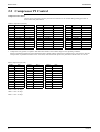
Compressor PI Control .......................................................................................56
Electronic Expansion Valve PI Control R-410A circuit.....................................57
Electronic Expansion Valve PI Control R-134a circuit......................................57
3. Special Control.................................................................................................. 58
3.1
3.2
3.3
3.4
Startup Control....................................................................................................58
Defrosting Operation ..........................................................................................59
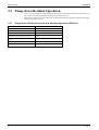
Pump-down Residual Operation.........................................................................60
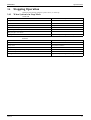
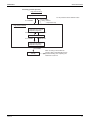
Stopping Operation.............................................................................................61
4. Protection Control ............................................................................................. 62
4.1
4.2
4.3
4.4
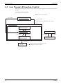
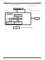
High Pressure Protection Control .......................................................................62
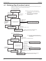
Low Pressure Protection Control........................................................................64
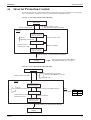
Discharge Pipe Protection Control .....................................................................66
Inverter Protection Control .................................................................................67
5. Other Control .................................................................................................... 69
5.1
5.2
5.3
Heating Operation Prohibition............................................................................69
Inverter Fan Control (Switch Box Fan) ..............................................................69
Crankcase Heater ................................................................................................69
6. Outline of Control (Indoor Unit)....................................................................... 70
6.1
6.2
Freeze Prevention ...............................................................................................70
Simultaneous demand of space heating and domestic water heating .................71
Part 6 - Test Operation................................................................. 77
1. Test Operation................................................................................................... 78
1.1
1.2
1.3
1.4
Procedure and Outline ........................................................................................78
Air Tight Test and Vacuum Drying....................................................................80
Additional Refrigerant Charge ...........................................................................81
Operation when Power is Turned On .................................................................85
2. Outdoor Unit PC Board Layout ........................................................................ 86
3. Field Setting ...................................................................................................... 87
3.1
3.2
Field Setting from remote control.......................................................................87
Field Setting from Outdoor Unit.......................................................................115
Part 7 - Troubleshooting............................................................. 127
1. Symptom-based Troubleshooting ................................................................... 129
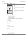
2. Troubleshooting by Remote Control............................................................... 131
2.1
2.2
2.3
2.4
2.5
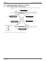
The INSPECTION / TEST Button ...................................................................131
Self-diagnosis by Wired Remote Control.........................................................132
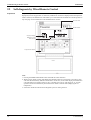
Operation of the Remote Controller’s Inspection / Test Operation Button......133
Remote Control Service Mode .........................................................................134
Remote Controller Self-Diagnosis Function ....................................................136
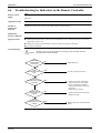
3. Troubleshooting by Indication on the Remote Controller .............................. 142
3.1
3.2
3.3
3.4
3.5
3.6
ii
“A1” Indoor Unit: PC Board Defect ..................................................................142
“A6” Indoor Unit: Pump Error (M1P) or Other Water System Error...............143
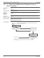
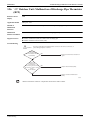
“A9” Indoor Unit: Malfunction of Moving Part of Electronic Expansion Valve
(K1E) R-410A circuit144
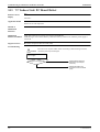
“AE” Indoor Unit: Water Circuit Error .............................................................146
“AJ” Indoor Unit: Malfunction of Capacity Determination Device.................147
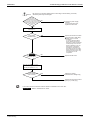
“C1” Indoor Unit: Failure of Transmission (Between Indoor unit PC Board and
Control PC Board)148
Table of Contents
ESIE09-08A
3.7
3.8
3.9
3.10
3.11
3.12
3.13
3.14
3.15
3.16
3.17
3.18
3.19
3.20
3.21
3.22
3.23
3.24
3.25
3.26
3.27
3.28
3.29
3.30
3.31
3.32
3.33
3.34
3.35
3.36
3.37
3.38
3.39
3.40
3.41
3.42
3.43
3.44
3.45
3.46
3.47
3.48
Table of Contents
“C4” Indoor Unit: Malfunction of Thermistor (R3T) Liquid Thermistor R-410A
150
“C5” Indoor Unit: Malfunction of Tank Thermistor (R2T)..............................151
“C9” Indoor Unit: Return Water Thermistor (R4T) .........................................152
“CA” Indoor Unit: Leaving Water Thermistor Error (R5T)..............................153
“CJ” Indoor Unit: Malfunction of Thermostat Sensor in Remote Controller ..154
“E1” Outdoor Unit: PC Board Defect................................................................155
“E1” Indoor Unit: PC Board Defect ..................................................................156
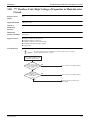
“E3” Outdoor Unit: Actuation of High Pressure Switch ..................................157
“E3” Indoor Unit: Actuation of High Pressure Switch .....................................159
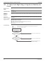
“E4” Outdoor Unit: Actuation of Low Pressure Sensor ...................................162
“E4” Indoor Unit: Actuation of Low Pressure Sensor......................................164
“E5” Outdoor Unit: Inverter Compressor Motor Lock.....................................166
“E5” Indoor Unit: Inverter Compressor Motor Lock .......................................167
“E7” Malfunction of Outdoor Unit Fan Motor .................................................168
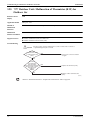
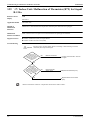
“E9” Outdoor Unit: Malfunction of Moving Part of Electronic Expansion Valve.
170
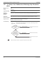
“E9” Indoor Unit: Malfunction of Moving Part of Electronic Expansion Valve
(K2E) R-134a circuit172
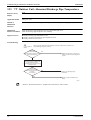
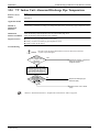
“F3” Outdoor Unit: Abnormal Discharge Pipe Temperature ...........................174
“F3” Indoor Unit: Abnormal Discharge Pipe Temperature ..............................175
“H9” Outdoor Unit: Malfunction of Thermistor (R1T) for Outdoor Air..........176
“J3” Outdoor Unit: Malfunction of Discharge Pipe Thermistor (R2T) ...........177
“J3” Indoor Unit: Malfunction of Discharge Pipe Thermistor (R6T)..............178
“J5” Outdoor Unit: Malfunction of Thermistor (R3T, R5T) for Suction Pipe 1, 2
179
“J5” Indoor Unit: Malfunction of Thermistor (R7T) for Liquid R-134a.........180
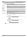
“J6” Outdoor Unit: Malfunction of Thermistor (R6T) for Outdoor Unit Heat Exchanger181
“J7” Outdoor Unit: Malfunction of Thermistor (R7T) for Outdoor Unit Liquid
Pipe182
“J9” Outdoor Unit: Malfunction of Thermistor (R4T) for Subcooling Heat Exchanger Gas Pipe183
“JA” Outdoor Unit: Malfunction of High Pressure Sensor ..............................184
“JA” Indoor Unit: Malfunction of High Pressure Sensor.................................185
“JC” Outdoor Unit: Malfunction of Low Pressure Sensor ...............................186
“JC” Indoor Unit: Malfunction of Low Pressure Sensor..................................187
“L1” Outdoor Unit: Malfunction of PC Board ..................................................188
“L1” Indoor Unit: Malfunction of PC Board .....................................................189
“L4” Outdoor Unit: Malfunction of Inverter Radiating Fin Temperature Rise 190
“L4” Indoor Unit: Malfunction of Inverter Radiating Fin Temperature Rise (R8T)
191
“L5” Outdoor Unit: Inverter Compressor Abnormal -
R-410A192
“L5” Indoor Unit: Inverter Compressor Abnormal -
R-134a193
“L8” Outdoor Unit: Inverter Current Abnormal ...............................................194
“L8” Indoor Unit: Inverter Current Abnormal..................................................195
“L9” Outdoor Unit: Inverter Start up Error ......................................................196
“L9” Indoor Unit: Inverter Start up Error .........................................................197
“LC” Outdoor Unit: Malfunction of Transmission between Inverter and Control
PC Board198
“LC” Indoor Unit: Malfunction of Transmission between Inverter and Control PC
iii
ESIE09-08A
3.49
3.50
3.51
3.52
3.53
3.54
3.55
3.56
3.57
3.58
3.59
3.60
3.61
3.62
3.63
Board199
“LH” Indoor Unit: Converter Error ...................................................................200
“P1” Outdoor Unit: High Voltage of Capacitor in Main Inverter Circuit .........201
“P1” Indoor Unit: High Voltage of Capacitor in Main Inverter Circuit............202
“PJ” Indoor Unit: Faulty Combination of PCB ...............................................203
“U0” Low Pressure Drop Due to Refrigerant Shortage or Electronic Expansion
Valve Failure204
“U2” Power Supply Insufficient or Instantaneous Failure................................206
“U2” Power Supply Insufficient or Instantaneous Failure................................208
“U4” Malfunction of Transmission between Indoor Unit and Outdoor Unit ...210
“U4” Malfunction of Transmission Indoor Unit...............................................212
“U5” Malfunction of Transmission between Remote Control and Indoor Unit .....
213
“U7” Indoor Unit: Malfunction of Transmission Outdoor Unit........................214
“U8” Malfunction of Transmission between Main and Sub Remote Controls.215
“UA” Communication Error between Outdoor Unit and Indoor Unit...............216
“UF” System is not Set yet ................................................................................217
“UH” Malfunction of System, Refrigerant System Address Undefined ...........218
Part 8 - Appendix ........................................................................ 223
1. Piping Diagrams.............................................................................................. 224
1.1
1.2
1.3
Outdoor Unit.....................................................................................................224
Indoor Unit........................................................................................................226
Switch Box Layout ...........................................................................................229
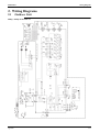
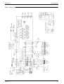
2. Wiring Diagrams............................................................................................. 233
2.1
2.2
2.3
3.
4.
5.
6.
Outdoor Unit.....................................................................................................233
Field Wiring Connection Diagram ...................................................................237
Indoor Unit........................................................................................................238
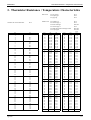
Thermistor Resistance / Temperature Characteristics .................................... 251
Pressure Sensor ............................................................................................... 254
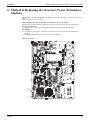
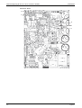
Method of Replacing the Inverter’s Power Transistors Modules ................... 255
External Backup Heater Kit ............................................................................ 258
6.1
6.2
6.3
6.4
6.5
6.6
6.7
6.8
6.9
Model Name .....................................................................................................258
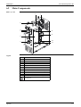
Main Components.............................................................................................259
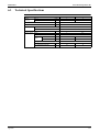
Technical Specifications...................................................................................261
Detailed Explanation of Setting Modes............................................................262
External Backup Heater Control.......................................................................263
Troubleshooting by Indication on the Remote Controller................................265
Troubleshooting: General Symptoms ...............................................................266
Switch Box Layout ...........................................................................................267
Wiring Diagrams ..............................................................................................269
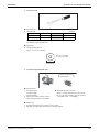
7. 3-Way Valve ................................................................................................... 273
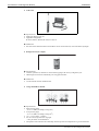
7.1
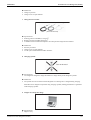
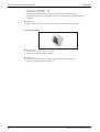
7.2
7.3
Build-Up of 3-Way Valve ................................................................................273
Troubleshooting Overview 3-Way Valve.........................................................274
How to Verify If 3-Way Valve is Installed Correctly ......................................275
Part 9- Precautions for New Refrigerant (R-410A) .................... 279
1. Precautions for New Refrigerant (R-410A) .................................................... 280
1.1
1.2
iv
Outline ..............................................................................................................280
Refrigerant Cylinders........................................................................................282
Table of Contents
ESIE09-08A
1.3
Service Tools ....................................................................................................283
Index ................................................................................................ i
Drawings & Flow Charts ............................................................... iii
Table of Contents
v
Introduction
ESIE09-08A
1. Introduction
1.1
Safety Cautions
Cautions and
Warnings
1.1.1
Be sure to read the following safety cautions before conducting repair work.
The caution items are classified into “
Warning” and “
Caution”. The “
Warning” items
are especially important since they can lead to death or serious injury if they are not followed closely.
Caution” items can also lead to serious accidents under some conditions if they are not
The “
followed. Therefore, be sure to observe all the safety caution items described below.
About the pictograms
This symbol indicates an item for which caution must be exercised.
The pictogram shows the item to which attention must be paid.
This symbol indicates a prohibited action.
The prohibited item or action is shown inside or near the symbol.
This symbol indicates an action that must be taken, or an instruction.
The instruction is shown inside or near the symbol.
After the repair work is complete, be sure to conduct a test operation to ensure that the equipment
operates normally, and explain the cautions for operating the product to the customer
Caution in Repair
Warning
Be sure to disconnect the power cable plug from the plug socket before disassembling
the equipment for a repair.
Working on the equipment that is connected to a power supply can cause an electrical
shock.
If it is necessary to supply power to the equipment to conduct the repair or inspecting
the circuits, do not touch any electrically charged sections of the equipment. Be careful
as the capacitors (top surfaces) can hold up to 220V.
If the refrigerant gas discharges during the repair work, do not touch the discharging
refrigerant gas.
The refrigerant gas can cause frostbite.
When disconnecting the suction or discharge pipe of the compressor at the welded
section, release the refrigerant gas completely at a well-ventilated place first.
If there is a gas remaining inside the compressor, the refrigerant gas or refrigerating
machine oil discharges when the pipe is disconnected, and it can cause injury.
If the refrigerant gas leaks during the repair work, ventilate the area. The refrigerant
gas can generate toxic gases when it contacts flames.
The step-up capacitor supplies high-voltage electricity to the electrical components of
the outdoor unit and indoor unit.
Be sure to discharge the capacitor completely before conducting repair work.
A charged capacitor can cause an electrical shock as the capacitors (top surfaces) can
hold up to 220V.
Do not start or stop the heat pump operation by plugging or unplugging the power cable
plug.
Plugging or unplugging the power cable plug to operate the equipment can cause an
electrical shock or fire.
vi
ESIE09-08A
Introduction
Caution
Do not repair the electrical components with wet hands.
Working on the equipment with wet hands can cause an electrical shock.
Do not clean the heat pump by splashing water.
Washing the unit with water can cause an electrical shock.
Be sure to provide the grounding when repairing the equipment in a humid or wet
place, to avoid electrical shocks.
Be sure to turn off the power switch and unplug the power cable when cleaning the
equipment.
The internal fan rotates at a high speed, and cause injury.
Do not tilt the unit when removing it.
The water inside the unit can spill and wet the furniture and floor.
Be sure to check that the refrigerating cycle section has cooled down sufficiently before
conducting repair work.
Working on the unit when the refrigerating cycle section is hot can cause burns.
Use the welder in a well-ventilated place.
Using the welder in an enclosed room can cause oxygen deficiency.
1.1.2
Cautions Regarding Products after Repair
Warning
Be sure to use parts listed in the service parts list of the applicable model and
appropriate tools to conduct repair work. Never attempt to modify the equipment.
The use of inappropriate parts or tools can cause an electrical shock, excessive heat
generation or fire.
When relocating the equipment, make sure that the new installation site has sufficient
strength to withstand the weight of the equipment.
If the installation site does not have sufficient strength and if the installation work is
not conducted securely, the equipment can fall and cause injury.
Be sure to use an exclusive power circuit for the equipment, and follow the technical
standards related to the electrical equipment, the internal wiring regulations and the
instruction manual for installation when conducting electrical work.
Insufficient power circuit capacity and improper electrical work can cause an electrical
shock or fire.
Be sure to use the specified cable to connect between the indoor and outdoor units.
Make the connections securely and route the cable properly so that there is no force
pulling the cable at the connection terminals.
Improper connections can cause excessive heat generation or fire.
When connecting the cable between the indoor and outdoor units, make sure that the
terminal cover does not lift off or dismount because of the cable.
If the cover is not mounted properly, the terminal connection section can cause an
electrical shock, excessive heat generation or fire.
vii
Introduction
ESIE09-08A
Warning
Do not damage or modify the power cable.
Damaged or modified power cable can cause an electrical shock or fire.
Placing heavy items on the power cable, and heating or pulling the power cable can
damage the cable.
Do not mix air or gas other than the specified refrigerant (R-410A / R-134a) in the
refrigerant system.
If air enters the refrigerating system, an excessively high pressure results, causing
equipment damage and injury.
If the refrigerant gas leaks, be sure to locate the leak and repair it before charging the
refrigerant. After charging refrigerant, make sure that there is no refrigerant leak.
If the leak cannot be located and the repair work must be stopped, be sure to perform
pump-down and close the service valve, to prevent the refrigerant gas from leaking into
the room. The refrigerant gas itself is harmless, but it can generate toxic gases when it
contacts flames, such as fan and other heaters, stoves and ranges.
Caution
Installation of a leakage breaker is necessary in some cases depending on the
conditions of the installation site, to prevent electrical shocks.
Do not install the equipment in a place where there is a possibility of combustible gas
leaks.
If a combustible gas leaks and remains around the unit, it can cause a fire.
Be sure to install the packing and seal on the installation frame properly.
For integral units only
If the packing and seal are not installed properly, water can enter the room and wet the
furniture and floor.
1.1.3
Inspection after Repair
Warning
Check to make sure that the power cable plug is not dirty or loose, then insert the plug
into a power outlet all the way.
If the plug has dust or loose connection, it can cause an electrical shock or fire.
If the power cable and lead wires have scratches or deteriorated, be sure to replace
them.
Damaged cable and wires can cause an electrical shock, excessive heat generation or
fire.
Do not use a joined power cable or extension cable, or share the same power outlet with
other electrical appliances, since it can cause an electrical shock, excessive heat
generation or fire.
Caution
Check to see if the parts and wires are mounted and connected properly, and if the
connections at the soldered or crimped terminals are secure.
Improper installation and connections can cause excessive heat generation, fire or an
electrical shock.
If the installation platform or frame has corroded, replace it.
Corroded installation platform or frame can cause the unit to fall, resulting in injury.
viii
ESIE09-08A
Introduction
Caution
Check the grounding, and repair it if the equipment is not properly grounded.
Improper grounding can cause an electrical shock.
Be sure to measure the insulation resistance after the repair, and make sure that the
resistance is 1 Mohm or higher.
Faulty insulation can cause an electrical shock.
Be sure to check the drainage of the indoor unit after the repair.
Faulty drainage can cause the water to enter the room and wet the furniture and floor.
1.1.4
Using Icons
Icons are used to attract the attention of the reader to specific information. The meaning of each icon is
described in the table below:
1.1.5
Using Icons List
Icon
Type of
Information
Note
Description
Caution
A “caution” is used when there is danger that the reader, through
incorrect manipulation, may damage equipment, loose data, get an
unexpected result or has to restart (part of) a procedure.
Warning
A “warning” is used when there is danger of personal injury.
Reference
A “reference” guides the reader to other places in this binder or in this
manual, where he/she will find additional information on a specific
topic.
A “note” provides information that is not indispensable, but may
nevertheless be valuable to the reader, such as tips and tricks.
Note:
Caution
Warning
ix
Introduction
1.2
ESIE09-08A
PREFACE
Thank you for your continued patronage of Daikin products.
This is the new service manual for Daikin's Year 2009 Daikin Altherma HT (high temperature) air to
water heat pump.
Daikin offers a wide range of models to respond to the residential heating market. We are confident that
customers will be able to find the models that best suit their needs.
This service manual contains information regarding the servicing of Daikin Altherma HT (R-410A & R134a) Heat Pump System.
August, 2009
After Sales Service Division
x
ESIE09-08A
Part 1 - General Information
1. Model Names of Indoor/Outdoor Units & Tanks ............................................... 2
General Information
1
Model Names of Indoor/Outdoor Units & Tanks
ESIE09-08A
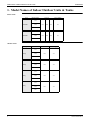
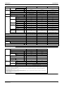
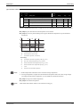
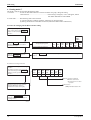
1. Model Names of Indoor/Outdoor Units & Tanks
Indoor Units
Type
Model Name
Version
Power Supply
011
EKHBRD
014
AA
AB
AC
V1
AA
AB
AC
Y1
016
011
EKHBRD
014
016
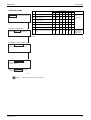
Outdoor Units
Type
Model Name
Version
Power Supply
AA
V1
AA
Y1
AA
V1
AA
Y1
011
ERRQ
014
016
011
ERRQ
014
016
011
ERSQ
014
016
011
ERSQ
014
016
2
General Information
ESIE09-08A
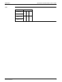
Model Names of Indoor/Outdoor Units & Tanks
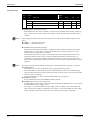
Tank
Model Name
Version
EKHTS 200
AA
AB
AC
AA
AB
AC
EKHTS 260
EKHTSU 200
EKHTSU 260
General Information
3
Model Names of Indoor/Outdoor Units & Tanks
4
ESIE09-08A
General Information
ESIE09-08A
Part 2 - Specifications
1. Specifications ...................................................................................................... 6
1.1
1.2
Specifications
Outdoor Units .......................................................................................................6
Indoor Unit............................................................................................................8
5
Specifications
ESIE09-08A
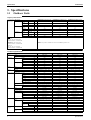
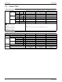
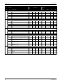
1. Specifications
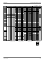
1.1
Outdoor Units
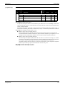
Capacity Information
For combination Indoor Units
indoor units +
Condition 1
outdoor units
Condition 2
Condition 3
Heating
capacity
Nominal
kW
Heating PI
Nominal
kW
COP
Nominal
Heating
capacity
Nominal
kW
Heating PI
Nominal
kW
COP
Nominal
Heating
capacity
Nominal
kW
Heating PI
Nominal
kW
COP
Nominal
EKHBRD011AA/AB/AC(V1/Y1)
EKHBRD014AA/AB/AC(V1/Y1)
EKHBRD016AA/AB/AC(V1/Y1)
11
14
16
3,57
4,66
5,57
3,08
3,00
2,88
11
14
16
4,40
5,65
6,65
2,50
2,48
2,41
11
14
16
2,61
3,55
4,31
4,22
3,94
3,72
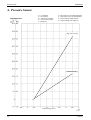
Notes
Condition 1
EW: 55°C, LW: 65°C, ΔT=10°C
Ambient conditions: 7°CDB/6°CWB
Condition 2
EW: 70°C, LW: 80°C, ΔT=10°C
Ambient conditions: 7°CDB/6°CWB
Remark:
This data is only valid in combination of indoor unit with ER(R/S)Q outdoor unit
Condition 3
EW: 30°C, LW: 35°C, ΔT=5°C
Ambient conditions: 7°CDB/6°CWB
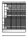
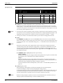
Technical Specifications
Outdoor units
Casing
Colour
Material
Dimensions
Unit
Packing
Painted galvanised steel
Painted galvanised steel
1345
1345
1345
900
900
900
Depth
mm
320
320
320
Height
mm
1524
1524
1524
Width
mm
980
980
980
Depth
mm
420
420
420
Unit
kg
120
120
120
Packed Unit
kg
130
130
130
Cardboard + Wood + EPS
Cardboard + Wood + EPS
Cardboard + Wood + EPS
Material
Length
Fin Pitch
kg
8
8
8
mm
857
857
857
2
2
2
2
2
2
10
10
10
mm
Nr of Passes
Face Area
1,131
1,131
1,131
Nr of Stages
m²
60
60
60
Empty Tubeplate Hole
0
0
0
Hi-XSS
Hi-XSS
Hi-XSS
Non-symmetric waffle louvre
Non-symmetric waffle louvre
Non-symmetric waffle louvre
Corrosion resistant
Corrosion resistant
Corrosion resistant
Propellor
Propellor
Propellor
2
2
2
Horizontal
Horizontal
Horizontal
Tube type
Fin
Type
Treatment
Type
Quantity
Discharge direction
Motor
Quantity
Model
Output
W
2
Brushless DC motor
70
70
70
Direct drive
Direct drive
1
1
1
Type
Hermetically sealed scroll
compressor
Hermetically sealed scroll
compressor
Hermetically sealed scroll
compressor
Direct on line
Direct on line
Direct on line
1
1
1
W
33
33
33
Minimum ambient
°C
-20
-20
-20
Maximum ambient
°C
20
20
20
Minimum ambient
°C
-20
-20
-20
Maximum ambient
°C
35
35
35
Crankcase
Heater
Domestic hot
water
2
Brushless DC motor
Direct drive
Starting Method
Heating
2
Brushless DC motor
Drive
Quantity
Motor
6
Daikin White
Painted galvanised steel
mm
Nr of Rows
Operation
Range (1)
ER(S/R)Q016AA(V1/Y1)
mm
Weight
Compressor
Daikin White
Width
Heat Exchanger Specifications
Fan
ER(S/R)Q014AA(V1/Y1)
Daikin White
Height
Packing
Weight
ER(S/R)Q011AA(V1/Y1)
Quantity
Output
Specifications
ESIE09-08A
Specifications
Outdoor units
ER(S/R)Q011AA(V1/Y1)
Sound Level
(nominal)
Heating
Refrigerant
Type
Sound Power
dBA
Sound Pressure
dBA
Charge
kg
Control
Nr of Circuits
Refrigerant Oil
Type
Charged Volume
Piping
Connections
Liquid
l
Quantity
Type
Diameter (OD)
Gas
mm
Quantity
Type
Diameter (OD)
Drain
Piping Length
mm
Quantity
ER(S/R)Q014AA(V1/Y1)
ER(S/R)Q016AA(V1/Y1)
See technical data
R-410A
R-410A
4,5
4,5
R-410A
4,5
Expansion valve (electronic)
Expansion valve (electronic)
Expansion valve (electronic)
1
1
1
Daphne FVC68D
Daphne FVC68D
Daphne FVC68D
1,5
1,5
1,5
1
1
1
Flare
Flare
Flare
9,52
9,52
9,52
1
1
1
Flare
Flare
Flare
15,9
15,9
15,9
3
3
3
26 x 3
26 x 3
26 x 3
Diameter (OD)
mm
Minimum
m
3
3
3
Maximum
m
50
50
50
Equivalent
m
63
63
63
Chargeless
m
10
10
10
see installation manual
see installation manual
see installation manual
30
30
30
Both liquid and gas pipes
Additional Refrigerant Charge
kg/m
Installation
height
difference
m
Maximum
Both liquid and gas pipes
Both liquid and gas pipes
Defrost Method
Heat Insulation
Reversed cycle
Reversed cycle
Reversed cycle
Defrost Control
Sensor for outdoor heat exchanger
temperature
Sensor for outdoor heat exchanger
temperature
Sensor for outdoor heat exchanger
temperature
Capacity Control Method
Inverter controlled
Inverter controlled
Inverter controlled
Safety Devices (pressure)
HPS
HPS
HPS
Safety Devices (fan)
Fan motor thermal protector
Fan motor thermal protector
Fan motor thermal protector
Safety Devices (inverter)
Inverter overload protector
Inverter overload protector
Inverter overload protector
PC board fuse
PC board fuse
PC board fuse
Installation manual
Installation manual
Installation manual
Safety Devices (pcb)
Standard
Accessories
Item
Quantity
1
1
1
40
40
40
Name
ER(S/R)Q(011/014/016)AAV1
ER(S/R)Q(011/014/016)AAY1
Phase
1~
3~
Design pressure (high pressure side)
bar
Notes
(1): for details see operation range TW drawing
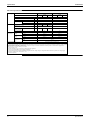
Electrical Specifications
Power Supply
Frequency
Hz
50
50
Voltage
V
220-240
380-415
Minimum
V
198
342
Maximum
V
254
440
Z-max (2)
Ω
0,28
-
Minimum Ssc (3) value
kVa
Equipment complying with EN/IEC
61000-3-12 (1)
-
Maximum
Heating
running Current
A
27
13,5
Recommended fuses
A
32
16
Quantity
2G
4G
Wire type
Note (4)
Voltage Range
Current
Wiring
Connections
For power
supply
For connection Quantity
with indoor unit
Remark
Power Supply Intake
Note (4)
2
F1+F2
Both indoor and outdoor unit
Notes
(1): European/International Technical Standard setting the limits for harmonic currents produced by equipment connected to public low-voltage systems
with input current > 16A and 75A per phase
(2): In accordance with EN/IEC 61000-3-11 (5), it may be necessary to consult the distribution network operator to ensure that the equipment is
connected only to a supply with Zsys (6) Zmax
(3): Short-circuit power
(4): Select diameter and type according to national and local regulations
(5): European/International Technical Standard setting the limits for voltage changes, voltage fluctuations and flicker in public low-voltage supply
systems for equipment with rated current 75A
(6): System impedance
Specifications
7
Specifications
1.2
ESIE09-08A
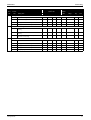
Indoor Unit
Capacity Information
For combination Indoor Units
indoor units +
Condition 1
outdoor units
Condition 2
Condition 3
EKHBRD011AA/AB/AC(V1/Y1)
Heating
capacity
Nominal
kW
Heating PI
Nominal
kW
COP
Nominal
Heating
capacity
Nominal
kW
Heating PI
Nominal
kW
COP
Nominal
Heating
capacity
Nominal
kW
Heating PI
Nominal
kW
COP
Nominal
EKHBRD014AA/AB/AC(V1/Y1)
EKHBRD016AA/AB/AC(V1/Y1)
11
14
16
3,57
4,66
5,57
3,08
3,00
2,88
11
14
16
4,40
5,65
6,65
2,50
2,48
2,41
11
14
16
2,61
3,55
4,31
4,22
3,94
3,72
Notes
Condition 1
EW: 55°C, LW: 65°C, ΔT=10°C
Ambient conditions: 7°CDB/6°CWB
Condition 2
EW: 70°C, LW: 80°C, ΔT=10°C
Ambient conditions: 7°CDB/6°CWB
Remark:
This data is only valid in combination of indoor unit with ER(R/S)Q outdoor unit
Condition 3
EW: 30°C, LW: 35°C, ΔT=5°C
Ambient conditions: 7°CDB/6°CWB
Technical Specifications
Indoor units
EKHBRD011AA/AB/AC(V1/Y1)
AA
Casing
Colour
Material
Dimensions
Packing
EKHBRD014AA/AB/AC(V1/Y1)
AA
AB
AC
EKHBRD016AA/AB/AC(V1/Y1)
AA
AB
Metallic Grey
Metallic Grey
Metallic Grey
pre coated sheetmetal
pre coated sheetmetal
pre coated sheetmetal
mm
860
860
860
Width
mm
680
680
680
Depth
mm
800
800
800
Height
mm
705
705
705
Width
mm
600
600
600
Depth
mm
695
695
695
Machine weight
kg
144,25 / 147,25
144,25 / 147,25
144,25 / 147,25
Gross weight
kg
Material
Weight
8
AC
Height
Packing
Unit
Weight
AB
kg
AC
153 / 156
153 / 156
153 / 156
EPS, Cardboard, MDF, Wood
(pallet), Metal
EPS, Cardboard, MDF, Wood
(pallet), Metal
EPS, Cardboard, MDF, Wood
(pallet), Metal
8,75
8,75
8,75
Specifications
ESIE09-08A
Specifications
Indoor units
Main
components
EKHBRD011AA/AB/AC(V1/Y1)
AA
Refrigerant side Type
heat exchanger
Quantity
AB
Cascade
compressor
Pump
Quantity
Crankcase
Heater
Output
W
Power input
W
Water filter
Refrigerant oil
Sound Level (3)
AISI 316
PPE foam
EPDM
type
Thermal
felt/foam
PPE foam
1
1
1
Hermetically sealed scroll
compressor
Hermetically sealed scroll
compressor
Hermetically sealed scroll
compressor
Direct online
94,0
Direct online
Direct online
1
1
1
1
1
33
33
33
33
33
DC motor
DC motor
DC motor
inverter controlled
inverter controlled
inverter controlled
92
92
91,9
88
88
89,7
85
87
95
101
Plate heat exchanger
Plate heat exchanger
Plate heat exchanger
1 (50 plates)
1 (50 plates)
1 (50 plates)
AISI 316
AISI 316
AISI 316
2,78
2,78
2,78
Water flow rate Nom. (1)
l/min
15,8
20,1
22,9
Water flow rate Max. (2)
l/min
31,6
40
EPDM
type
Thermal
felt/foam
PPE
EPDM
type
Thermal
felt/foam
PPE
Thermal
felt/foam
l
12
12
12
Max. water pressure
bar
3
3
3
Pre pressure
bar
1
1
1
Diameter perforations
mm
1
1
1
Brass
Brass
Brass
Piping connections diameter
inch
G 1”1/4 (female)
G 1”1/4 (female)
G 1”1/4 (female)
Piping
inch
1”
1”
1”
Safety valve
bar
3
3
3
Manometer
Y/N
Y
Y
Y
Drain valve / Fill valve
Y/N
Y
Y
Y
Shut off valve
Y/N
Y
Y
Y
Air purge valve
Y/N
Y
Y
Y
20
20
20
Heating water system maximum water volume l
400
400
400
Gas side diameter
mm
15,9
15,9
15,9
Liquid side diameter
mm
Type
Casc.
Charged amount
Casc.
Design pressure (high pressure side)
bar
38
38
38
Type
Casc.
Daphne FVC68D
Daphne FVC68D
Daphne FVC68D
Charged amount
Casc.
1,5l
1,5l
1,5l
Sound Pressure at 55 - 65 °C [EW - LW] (4)
dBA
43
45
46
Sound Pressure at 70 - 80 °C [EW - LW] (4)
dBA
46
46
46
Sound Pressure low sound mode n° 1 at 55 - 65 dBA
°C [EW - LW] (4)
40
43
45
Operation range Ambient
(5)
Waterside
Installation place
85
45,8
EPDM
type
Volume
Heating water system minimum water volume l
Refrigerant
Circuit
PPE foam
Thermal
felt/foam
l
Material
Water circuit
Thermal
felt/foam
EPDM
type
Water volume
Insulation material
AC
1 (60 plates)
Material
Expansion
vessel
AB
AISI 316
Nr. of speed
Water side Heat Type
exchanger
Quantity
AA
1 (60 plates)
Type
kPa
EKHBRD016AA/AB/AC(V1/Y1)
AISI 316
33
Nominal ESP Heating
unit (1)
AC
1 (60 plates)
Starting Method
Crankcase
Heater
AB
Plate heat exchanger
EPDM
type
Type
AA
Plate heat exchanger
Quantity
Motor
EKHBRD014AA/AB/AC(V1/Y1)
Plate heat exchanger
Material
Insulation material
AC
9,52
9,52
9,52
R134a
R134a
R134a
Minimum
°C
-20
-20
-20
Maximum
°C
20/(35)(6)
20/(35)(6)
20/(35)(6)
Minimum LW
°C
25
25
25
Maximum LW
°C
80
80
80
Indoor
Indoor
Indoor
PPE
Notes
(1): for ΔT = 10°C
(2): for ΔT = 5°C
(3): The data mentioned is valid in free field condition because it is measured in a semi-anechoic room. Measured value under actual installation conditions will be higher due to environmental
noise and sound reflections. These values are sound pressure levels measured at all sides (front / back / left / right / top) at 1m distance (see engineering data book for more details). The values
do not occur simultaneously on all mentioned sides
(4): EW = entering water temperature - LW = leaving water temperature
(5): for details see operation range TW drawing
(6): for DHW operation
Specifications
9
Specifications
ESIE09-08A
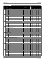
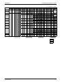
Electrical Specifications
Power Supply
Name
EKHBRD(011/014/016)AA/AB/
ACV1
11
Phase
Wiring
Connections
16
11
14
1~
Hz
50
50
Voltage
V
220-240
380-415
Minimum
V
198
342
Maximum
V
254
Z-max (2)
Ω
Minimum Ssc (3) value
kVa
Maximum
Heating
running Current
A
Recommended fuses
A
0,34
440
0,32
0,32
-
Equipment complying with EN/IEC
61000-3-12 (1)
22,5
23,8
-
23,8
12,5
25
16
2G
4G
For power
supply
Quantity
Wire type
Note (4)
Note (4)
For power
supply (5)
Quantity
2G + 2G
4G + 2G
Wire type
Note (4)
For connection
with outdoor
unit
Quantity
Power Supply Intake
Remark
16
3~
Frequency
Voltage Range
Current
14
EKHBRD(011/014/016)AA/AB/
ACY1
Note (4)
2
F1+F2
Both indoor unit and outdoor unit
Notes
(1): European/International Technical Standard setting the limits for harmonic currents produced by equipment connected to public low-voltage systems
with input current > 16A and 75A per phase
(2): In accordance with EN/IEC 61000-3-11 (6), it may be necessary to consult the distribution network operator to ensure that the equipment is
connected only to a supply with Zsys (7) Zmax
(3): Short-circuit power
(4): Select diameter and type according to national and local regulations
(5): In case of benefit kWh rate power supply installations
(6): European/International Technical Standard setting the limits for voltage changes, voltage fluctuations and flicker in public low-voltage supply
systems for equipment with rated current 75A
(7): System impedance
10
Specifications
ESIE09-08A
Part 3 - Refrigerant Circuit
& Functional Parts
1. Refrigerant Circuit ............................................................................................ 12
1.1 Outdoor Unit............................................................................................ 12
1.2 Indoor Unit .............................................................................................. 14
2. Functional Parts Layout .................................................................................... 17
2.1
2.2
2.3
2.4
2.5
2.6
Refrigerant Circuit
ERRQ 011/014/016 AAV1, ERSQ 011/014/016 AAV1....................................17
ERRQ 011/014/016 AAY1, ERSQ 011/014/016 AAY1....................................19
EKHBRD 011/014/016 AA(V1/Y1) ..................................................................21
EKHBRD 011/014/016 AB/AC(V1/Y1)............................................................23
EKHTS 200/260 A/AB/AC ................................................................................24
EKHTSU 200/260 A/AB/AC .............................................................................26
11
Refrigerant Circuit
ESIE09-08A
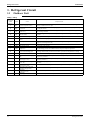
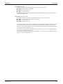
1. Refrigerant Circuit
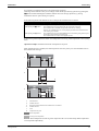
1.1
Outdoor Unit
ERRQ - ERSQ
No. in
refrigerant
system
diagram
Symbol
A
M1C
Inverter compressor (INV)
Inverter compressor is operated on frequencies between 36 Hz and 195 Hz by using the
inverter. In total there are 31 steps.
B
M1F
M2F
Inverter fan
Since the system is of air heat exchanging type, the fan is operated at 8 (9)-step rotation speed
by using the inverter.
C
Y1E
Electronic expansion valve
(Main: EV1)
While in heating operation, PI control is applied to keep the outlet superheated degree of air
heat exchanger constant.
D
Y3E
Electronic expansion valve
(Subcool: EV3)
Pl control is applied to keep the outlet superheated degree of subcooling heat exchanger
constant.
E
Y2S
Solenoid valve (Hot gas: SVP)
Used to prevent the low pressure from transient falling.
F
Y3S
Solenoid valve (Unload circuit
SVUL)
Used to the unloading operation of compressor.
G
Y1S
Four way valve
Used to switch the operation mode between defrosting and heating. Activated during heating
(opposite concerning indoor unit).
12
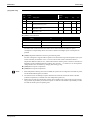
Name
Major Function
H
S1NPH High pressure sensor
Used to detect high pressure.
I
S1NPL
Low pressure sensor
Used to detect low pressure.
In order to prevent the increase of high pressure when a malfunction occurs, this switch is
activated at high pressure of 4.0 MPa or more to stop the compressor operation.
J
S1PH
HP pressure switch (For INV
compressor)
K
—
Pressure regulating valve 1
(Receiver to discharge pipe)
This valve opens at a pressure of 4.0 MPa for prevention of pressure increase, thus resulting in
no damage of functional parts due to the increase of pressure in transportation or storage.
1
R1T
Thermistor (Outdoor air: Ta)
Used to detect outdoor temperature, correct discharge pipe temperature, and others.
2
R2T
Thermistor (INV discharge pipe:
Tdi)
used to detect discharge pipe temperature, make the temperature protection control of
compressor, and others.
3
R3T
Thermistor
(Suction pipe1: Ts1)
used to detect suction pipe temperature, keep the suction superheated degree constant in heating
operation, and others.
4
R4T
Thermistor (Heat exchanger
deicer: Tb)
Used to detect liquid pipe temperature of air heat exchanger, determine defrosting operation,
and others.
5
R5T
Thermistor
(Suction pipe2: Ts2)
Used to the calculation of superheat and internal temperature of compressor etc.
6
R6T
Thermistor (Subcooling heat
exchanger gas pipe: Tsh)
Used to control of subcooling electronic expansion valve.
7
R7T
Thermistor
(Liquid pipe1: Tl1)
Liquid thermistor (internal control), and others.
8
R8T
Thermistor
(Liquid pipe2: Tl2)
Liquid thermistor (internal control), and others.
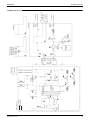
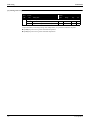
Refrigerant Circuit
R5T
A
COMPRESSOR
(M1C)
Low pressure
I sensor (S1NPL)
R6T
SP
K
F
SV
R2T
DEFROST
HEATING
J
FILTER
SOLENOID VALVE
(Y3S)
R3T
G
CAPILLARY
TUBE
HIGH
PRESSURE
SWITCH
(S1PH)
PRESSURE REGULATING
VALVE
ELECTRONIC
EXPANSION
VALVE (Y1E)
STOP VALVE (WITH SERVICE PORT ON FIELD PIPING SIDE ø 7.9MM FLARE CONNECTION)
ACCUMULATOR
FILTER
R7T
DOUBLE PIPE
HEAT EXCHANGER
C
p>
Refrigerant Circuit
4-WAY VALVE
(Y1S)
FILTER
R8T
R4T
CAPILLARY
TUBE
FILTER
M2F
SOLENOID VALVE
(Y2S)
SV
E
FANS B
M1F
R1T
SERVICE PORT
HIGH PRESSURE
H
SENSOR (S1NPH)
SP
HEAT
EXCHANGER
OIL SEPARATOR
ELECTRONIC
EXPANSION D
VALVE (Y3E)
ESIE09-08A
Refrigerant Circuit
13
Refrigerant Circuit
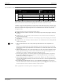
1.2
ESIE09-08A
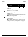
Indoor Unit
EKHBRD 011/014/016 AA/AB/AC(V1/Y1)
No. in
refrigerant
system
diagram
Symbol
A
M1C
Inverter compressor on R-134a
Inverter compressor is operated on frequencies between 40 Hz and 210 Hz by using the
inverter. Max. of 30 steps.
B
Y1R
Four way valve
Used to switch the operation mode between heating and defrost. Not activated during heating
(opposite concerning outdoor unit).
C
B1PL
Low pressure sensor
Used to detect low pressure.
D
B1PH
High pressure sensor
Used to detect high pressure.
E
S1PH
High pressure switch
In order to prevent the increase of high pressure when a malfunction occurs, this switch is
activated at high pressure of 3.8 MPa or more to stop the compressor operation.
14
Name
Major Function
F
K2S
2-way valve
Used during defrost operation.
G
K1E
Electronic expansion valve
Used to regulate the refrigerant flow of R-410A.
H
K2E
Electronic expansion valve
Used to regulate the refrigerant flow of R-134a.
I
E1HC
Crankcase heater
Used to prevent migration (when the unit is OFF) and condensation of refrigerant in the
crankcase of compressor.
J
M1P
DC inverter pump
Used to regulate water flow to achieve a constant ΔT.
K
Q2L
Thermistor protector water
piping
Used to protect the water system against high temperatures.
L
K1S
3 way valve (option for water
tank)
Used to switch over between space heating and domestic hot water.
1
R3T
Liquid thermistor R-410A
Subcool calculation.
2
R6T
Discharge thermistor
Used to detect discharge pipe temperature, make the temperature protection control of
compressor, and others.
3
R7T
Liquid thermistor R-134a
Subcool calculation.
4
R4T
Returning water thermistor
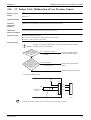
Used to control and protect the water system.
5
R5T
Leaving water thermistor
Used to control and protect the water system.
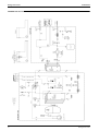
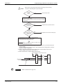
Refrigerant Circuit
Refrigerant Circuit
C
ACCUMULATOR
M1C
A
HEATING
DEFROST
REFRIGERANT SIDE
B1PL
2
R6T
B1PH
I E1HC
D
E
SERVICE PORT
5/16”
S1PH
FILTER
PLATE HEAT
EXCHANGER
R-410A /
R-134a
SERVICE PORT
5/16”
FILTER
1 R3T
F
K2E H
FIELD PIPING ø9.5 C 1220T-0
FILTER
FILTER
CHECK
VALVE
FIELD PIPING ø15.9 C 1220T-0
R7T 3
K2S
K1E G
SV
CHECK
VALVE
B
Y1R
*R*Q011~016**
OUTDOOR UNIT
PLATE
HEAT
EXCHANGER
R-134a
5
K
4
R4T
Q2L
R5T
1
J
EXPANSION
VESSEL
DRAIN VALVE
M1P
3-WAY
M K1S L
VALVE
FIELD INSTALLATION
(DELIVERED WITH
OPTION DOMESTIC
HOT WATER TANK)
PRESSURE
GAUGE
AIR
PURGE
SAFETY
VALVE
BLOW
OFF
1
1
FILTER
SHUT OFF
VALVE
SHUT OFF
VALVE
WATER SIDE
STANDARD
G 1”1/4 (female)
WATER INLET
G 1”1/4 (female)
*KHTS*
200~270*
OPTION DOMESTIC HOT
WATER TANK
WATER OUTLET
ESIE09-08A
Refrigerant Circuit
EKHBRD 011/014/016 AA(V1/Y1)
15
Refrigerant Circuit
ESIE09-08A
EKHBRD 011/014/016 AB/AC(V1/Y1)
16
Refrigerant Circuit
ESIE09-08A
Functional Parts Layout
2. Functional Parts Layout
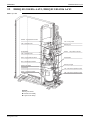
2.1
ERRQ 011/014/016 AAV1, ERSQ 011/014/016 AAV1
Bird’s-eye view
Y2S Solenoid valve
S1NPH High pressure sensor
Oil separator
Y1S 4-way valve
Service port
S1NPL Low pressure sensor
Accumulator
Y3S Solenoid valve
S1HP High pressure switch
R2T Discharge thermistor
Service port liquid
Service port gas
Y1E Electric expansion valve
Y3E Electric expansion valve
E1HC Crankcase heater
Compressor
Remark:
Bottom plate heater:
Standard for ERRQ
Optional for ERSQ
Refrigerant Circuit
17
Functional Parts Layout
ESIE09-08A
Back view
R6T Subcool thermistor
R3T Suction 1 thermistor
R5T Suction 2 thermistor
R1T Ambient thermistor
R8T Liquid pipe 2 thermistor
R4T Coil thermistor
R7T Liquid pipe 1 thermistor
18
Refrigerant Circuit
ESIE09-08A
2.2
Functional Parts Layout
ERRQ 011/014/016 AAY1, ERSQ 011/014/016 AAY1
Bird’s-eye view
S1NPH High pressure sensor
Y1S 4-way valve
Y2S Solenoid valve
Oil separator
Service port
S1NPL
Low pressure sensor
Y3S Solenoid valve
S1PH High pressure switch
Accumulator
R2T Discharge thermistor
Service port liquid
Compressor
E1HC Crankcase heater
Service port gas
Y1E Electronic expansion valve
Y3E Electronic expansion valve
Remark:
Bottom plate heater:
Standard for ERRQ
Optional for ERSQ
Refrigerant Circuit
19
Functional Parts Layout
ESIE09-08A
Back view
R6T Subcool gas pipe thermistor
R3T Suction thermistor
R1T
Ambient thermistor
R8T Liquid pipe thermistor
R7T
20
Liquid pipe thermistor
Refrigerant Circuit
ESIE09-08A
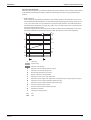
2.3
Functional Parts Layout
EKHBRD 011/014/016 AA(V1/Y1)
Front view
15
14
13 12
11
1
2
10
A
9
8
3
7
4
5
6
Top view
20
19
18
17
E
16
Refrigerant Circuit
21
Functional Parts Layout
ESIE09-08A
Bird’s-eye view
D
28
27
21
22
23
7
A
26
25
C
B
24
Legend
No.
1
2
3
4
5
6
7
8
9
10
11
12
13
14
15
16
17
22
Name
High pressure sensor
High pressure switch
Compressor R-134a
Outlet water connection
Inlet water connection
Filter
Solenoid valve
Expansion vessel 12 l
DC inverter pump
Pressure relief valve
Manometer
High pressure service port R-134a
Low pressure service port R-134a
Heat exchanger: refrigerant - water
Heat exchanger: refrigerant - refrigerant
(Q2L) Thermal protector water piping
Air purge valve
No.
18
19
20
21
22
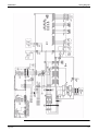
23
24
25
26
27
28
A
B
C
D
E
Name
Refrigerant liquid connection R-410A
Refrigerant gas connection R-410A
Return water connection from tank
Low pressure sensor
4-way valve (R-134a)
Accumulator R-134a
Drain
Electronic expansion valve R-134a
Electronic expansion valve R-410A
Refrigerant gas connection R-410A
Refrigerant liquid connection R-410A
R6T Discharge thermistor
R7T Liquid thermistor R-134a
R3T Liquid thermistor R-410A
R4T Returning water thermistor
R5T Leaving water thermistor
Refrigerant Circuit
ESIE09-08A
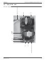
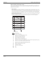
2.4
Functional Parts Layout
EKHBRD 011/014/016 AB/AC(V1/Y1)
Overview
Legend
No.
1
2
3
4
5
6
7
8
9
10
11
12
Refrigerant Circuit
Name
Air purge valve
Thermistors
Switchbox
Heat exchangers
Refrigerant liquid connection R410A
Refrigerant gas connection R410A
Shut-off valves
Water inlet connection
Water outlet connection
Drain valve
Water filter
Expansion vessel (12l)
No.
13
14
15
16
17
18
19
20
21
22
23
24
Name
Manometer
Pump
Pressure relieve valve
Service ports R134a
Compressor R-134a
Accumulator
3-way valve (option, with EKHTS tank))
4-way valve
2-way valve
Thermal cut-out
Electronic expansion valve
T-piece (option, with EKHTS tank)
23
Functional Parts Layout
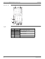
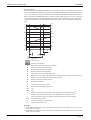
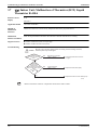
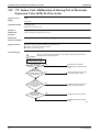
2.5
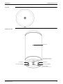
ESIE09-08A
EKHTS 200/260 A/AB/AC
Front view
Tank sensor
Bottom view
Tank sensor
Recirculation connection
Hot water out
Coil in
from EKHBRD
24
Cold water in
Coil out
towards EKHBRD
Refrigerant Circuit
ESIE09-08A
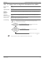
Functional Parts Layout
Top view
Worm’s-eye view
Tank sensor
Recirculation connection
Hot water out
Coil in (from EKHBRD)
Cold water in
Coil out (to EKHBRD)
Bottom adaptor
Refrigerant Circuit
25
Functional Parts Layout
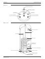
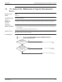
2.6
ESIE09-08A
EKHTSU 200/260 A/AB/AC
Front view
Tank sensor
26
Refrigerant Circuit
ESIE09-08A
Functional Parts Layout
Bottom view
Pressure relief connection
Recirculation connection
Hot water out
Coil in (from EKHBRD)
Cold water in
Coil out (towards EKHBRD)
Bird’s-eye view
Pressure relief connection
Anode
Hot water pipe
Heat exchanger
Recirculation pipe
Coil out connection towards EKHBRD
Coil in connection from EKHBRD
Cold water in connection
Recirculation connection
Hot water out connection
Refrigerant Circuit
27
Functional Parts Layout
28
ESIE09-08A
Refrigerant Circuit
ESIE09-08A
Part 4 - Electrical Circuit
1. Switch Box Layout - Indoor Unit EKHBRD .................................................... 30
2. PCB Layout for EKHBRD 011/014/016 AA/AB/AC V1/Y1 .......................... 34
2.1
2.2
2.3
2.4
2.5
2.6
2.7
2.8
2.9
Refrigerant Circuit
Main PCB - A1P.................................................................................................34
Control - PCB - A3P...........................................................................................36
Inverter PCB - A4P.............................................................................................38
Filter PCB - A6P.................................................................................................41
QA PCB - A5P....................................................................................................43
Inverter Control PCB - Three Phase - A4P ........................................................44
Inverter PCB - Three Phase - A5P......................................................................46
Digital I/O PCB (Option PCB A7P)...................................................................48
Demand PCB (Option PCB A8P).......................................................................50
29
Switch Box Layout - Indoor Unit EKHBRD
ESIE09-08A
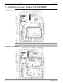
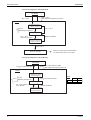
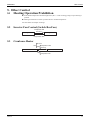
1. Switch Box Layout - Indoor Unit EKHBRD
EKHBRD 011/014/016 AAV1
EKHBRD 011/014/016 AAY1
30
Refrigerant Circuit
ESIE09-08A
Switch Box Layout - Indoor Unit EKHBRD
Legend
No.
1
2
3
4
5
6
7
8
9
10
11
12
13
14
15
16
17
18
19
20
21
22
23
Refrigerant Circuit
Name
Main PCB (A1P)
Control PCB (A3P)
Inverter PCB (A5P)
Inverter control PCB (A4P) (only Y1)
QA PCB (A5P) (only V1)
Filter PCB (A6P)
Digital I/O PCB (A7P ) (Optional)
Demand PCB (A8P) (Optional)
Terminal block X1M: Main power supply
Terminal block X2M: AC connections
Terminal block X3M: DC connections
DC connector X1Y
Pump connector X2Y
AC connectory X3Y
Cable tie mountings
Power wiring entry
AC field wiring entry
DC field wiring entry
Compressor cable entry
Interface relay K1A
Wiring bridges
Fuse F1 (Only Y1)
Fuse F2 (Only Y1)
31
Switch Box Layout - Indoor Unit EKHBRD
ESIE09-08A
EKHBRD 011/014/016 AB/AC V1
EKHBRD 011/014/016 AB/AC Y1
32
Refrigerant Circuit
ESIE09-08A
Switch Box Layout - Indoor Unit EKHBRD
Legend
No.
1
2
3
4
5
6
7
8
9
10
11
12
13
14
15
16
17
18
19
20
21
22
23
Refrigerant Circuit
Name
Main PCB (A1P)
Control PCB (A3P)
Inverter PCB (A5P)
Inverter control PCB (A4P) (only Y1)
QA PCB (A5P) (only V1)
Filter PCB (A6P)
Digital I/O PCB (A7P ) (Optional)
Demand PCB (A8P) (Optional)
Terminal block X1M: Main power supply
Terminal block X3M: DC connections
Terminal block X2M: AC connections
DC connector X1Y
Pump connector X2Y
AC connectory X3Y
Cable tie mountings
Power wiring entry
AC field wiring entry
DC field wiring entry
Compressor cable entry
Interface relay K1A
Wiring bridges
Fuse F1 (Only Y1)
Fuse F2 (Only Y1)
33
PCB Layout for EKHBRD 011/014/016 AA/AB/AC V1/Y1
ESIE09-08A
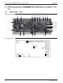
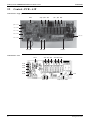
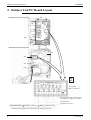
2. PCB Layout for EKHBRD 011/014/016 AA/AB/AC V1/
Y1
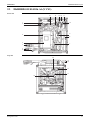
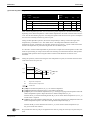
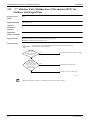
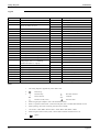
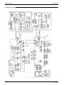
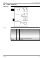
2.1
Main PCB - A1P
Main PCB - single phase
Fuse
3,15A 250V
X60A X19A X35A X33A
blue white white white
green
X6A
yellow
X85A
white
X50A X7A
white white
X36A red
black X27A
X16A white
X17A yellow
X12A
X18A
X24A
X15A
yellow
red
black
white
X23A blue
white X25A
X30A white
X65A
white
X20A
white
X38A
white
SS1
X70A
yellow
X65A
34
X20A
X38A
X23A
X25A
X24A
EMG
X36A
X16A
NORMAL
X15A X18A
X50A
X7A
X85A
X30A
SS1
X6A
X12A X17A
X60AX19AX35A X33A
X70A
X27A
Main PCB - A1P
Refrigerant Circuit
ESIE09-08A
PCB Layout for EKHBRD 011/014/016 AA/AB/AC V1/Y1
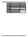
Legend
Connector
SS1
X6A
X7A
X12A
X15A
X16A
X17A
X18A
X19A
X20A
X23A
X24A
X25A
X27A
X30A
X33A
X35A
X36A
X38A
X50A
X60A
X65A
X70A
X85A
Connected to
Emergency switch
K1E: electronic expansion valve
R4T: returning water thermistor
R5T: leaving water thermistor
R3T: liquid thermistor R-410A
M1P: DC inverter pump
X803A of PCB A5P
X3M
[3; 4 -> F1 F2]
[7; 8 -> P1 P2]
X2A of PCB A7P*
X10A of PCB A3P
X15A of PCB A3P
X80A of PCB A8P*
Color
Yellow
White
Yellow
White
White
Yellow
Red
White
White
Blue
Black
White
Black
White
White
White
Red
White
White
Blue
White
Yellow
White
*: A7P, A8P= option PCB; connection not standard
Refrigerant Circuit
35
PCB Layout for EKHBRD 011/014/016 AA/AB/AC V1/Y1
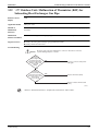
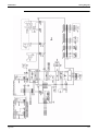
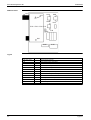
2.2
ESIE09-08A
Control - PCB - A3P
Control PCB - single phase
X21A
white
X3A
X4A
orange yellow
X5A
black
X7A
pink
X8A X23A
green white
yellow X11A
blue X12A
white X25A
white X13A
X1A blue
white X14A
X15A X16A
black yellow
X10A X9A
white white
Fuse
3,15A 250V
Control PCB - A3P
X21A
X3A X4A X5A
X7A X8A X23A
X11A
X12A
X25A
X13A
EB0750
X14A
X10A X9A
36
X1A
Fuse= 3,15A 250V
Refrigerant Circuit
ESIE09-08A
PCB Layout for EKHBRD 011/014/016 AA/AB/AC V1/Y1
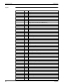
Legend
Connector
X1A
X3A
X4A
X5A
X7A
X8A
X9A
X10A
X11A
X12A
X13A
X14A
X15A
X16A
X21A
X23A
X25A
Color
Blue
Orange
Yellow
Black
Pink
Green
White
White
Yellow
Blue
White
White
Black
Yellow
White
White
White
Connected to
X2M [12 - 13]
X2M [3 - 4]
2-way valve (R-410A)
Bridge with filter capacitors
X35A of PCB A1P -> 16V power supply
R2T*1
X3M [7 - 8]*2
X15A of PCB A1P
Bridge
X2M [14 - 15 -16]
-
*1: Only for EKHTS
*2: Only for benefit kWh rate power supply installation
Refrigerant Circuit
37
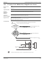
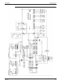
38
X27A
X51A
pink
blue
X77A
LD
yellow
orange
Fuse 2 6,3A 250V for Y1S/ECHC
X28A
grey
HAP= LED
X25A
LC
red
NC
blue
X21A
white
X5A
white
U
V
W
red white blue
X9A
white
N
grey
X6A
white
blue
white
orange
P
white
LE
X111A
Fuse 1 5A 250V for 111F/112F
X107A white
X41A
X106A red
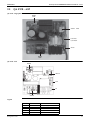
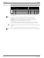
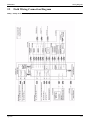
2.3
blue
X32A X17A X18A X12A X11A X13A
white red blue blue white white
PCB Layout for EKHBRD 011/014/016 AA/AB/AC V1/Y1
ESIE09-08A
Inverter PCB - A4P
Inverter PCB - single phase
Refrigerant Circuit
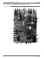
ESIE09-08A
PCB Layout for EKHBRD 011/014/016 AA/AB/AC V1/Y1
Inverter PCB
X106A X107A
F6U
X111A
P
EC09008
X6A
N
WVU
X9A
X5A
LE
X21A
X13A
X11A
X12A
X51A
X41A
X18A
NC
X17A
X32A
LC
X25A
HAP X28A X77A
LD
F4U
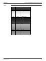
Legend
Refrigerant Circuit
Connector
X5A
X6A
X9A
X11A
Color
White
White
White
White
X12A
Blue
X13A
X17A
X18A
X21A
X25A
X27A
X28A
X32A
X41A
White
Red
Blue
White
Blue
Pink
Grey
White
Blue
Connected to
Function
X809A of PCB A5P
R6T by connector X1Y [13, 14]
R7T by connector X1Y [15, 16]
B1PH by connector X1Y [17, 18, 19]
B1PL by connector X1Y [20 - 21 - 22]
K2E by connector X1Y [25 - 26 - 27 - 28 - 29 - 30]
Y1R by connector X3Y [7 - 8]
M1F & M2F
E1HC by connector X3Y [5 - 6]
K1A
-
QA PCB
Discharge & liquid [R-134a]
thermistor
High pressure sensor
Low pressure sensor
Electronic expansion valve
4-way valve
Switch box cooling fan
Crankcase heater
Interface relay of S1PH & Q2L
Service purpose
39
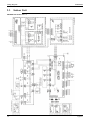
PCB Layout for EKHBRD 011/014/016 AA/AB/AC V1/Y1
X51A
X77A
X106A
X107A
X111A
HAP
Fuse 1
Fuse 2
LC
LD
LE
NC
N
P
U
V
W
40
Blue
Yellow
Red
White
White
LED
Red
Orange
White
Blue
Grey
Orange
Red
White
Blue
ESIE09-08A
K1A & connector X3Y [9, 10]
R8T
LB of PCB A6P
Interface relay of S1PH & Q2L
Fin thermistor
Indication power supply
5A, 250V for M1F, M2F
6,3A, 250V for Y1S, ECHC
Filter PCB
R1L by connector X4Y [1, 2]
Reactor
NB of PCB A6P
C1C1+
U of M1C
V of M1C
W of M1C
Capacitor C1
Compressor
Refrigerant Circuit
ESIE09-08A
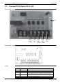
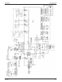
2.4
PCB Layout for EKHBRD 011/014/016 AA/AB/AC V1/Y1
Filter PCB - A6P
LB
red
NB blue
Refrigerant Circuit
LA
red
green cable + white connector earth
LB
blue
LF
NF
Fuse F1U
6,3A 250V
Connector of LF - NF white
Filter PCB - single phase
41
PCB Layout for EKHBRD 011/014/016 AA/AB/AC V1/Y1
ESIE09-08A
Filter PCB - A6P
NB
LB
F1U
NF
LF
NA
LA
E
Legend
Connector
LA
NA
LB
NB
LF
NF
E
F1U
42
Color
Red
Blue
Red
Blue
Red
Blue
Green cable,
white connector
-
Connected to - function
X1M [L - N] Power supply 1~230V
LC - NC Inverter PCB
X2M [10 - 11] via V5C
Earth
6,3A 250V [fuse]
Refrigerant Circuit
ESIE09-08A
2.5
PCB Layout for EKHBRD 011/014/016 AA/AB/AC V1/Y1
QA PCB - A5P
QA PCB - single phase
X809A
white
X801A
white
Fuse F3U
6,3A 250V
Green
X803A
black
QA PCB - A5P
X809A
X801A
F3U
E3
X803A
Legend
Connector
X801A
X803A
X809A
F3U
E3
Refrigerant Circuit
Color
White
Black
White
Green
Connected to - function
X2M [8 - 9] by V5C
X27A of main PCB A1P
X9A of invertor PCB A4P
Fuse 6,3A / 250V
Earth
43
PCB Layout for EKHBRD 011/014/016 AA/AB/AC V1/Y1
2.6
ESIE09-08A
Inverter Control PCB - Three Phase - A4P
Inverter control PCB - three phase
X803A
X77A
X25A X28A X27A
NA
L3A
L2A
L1A
F2U
F1U
X6A
F5U
X21A
X41A
X12A
L11A
X11A
X13A
N1A
X17A
L21A
X18A
L31A
X5A
44
X4A
X9A
X8A
F4U
F3U
Refrigerant Circuit
ESIE09-08A
PCB Layout for EKHBRD 011/014/016 AA/AB/AC V1/Y1
Legend
Connector
L1A
L2A
L3A
NA
L11A
L12A
L13A
N1A
X4A
X5A
X6A
X8A
X9A
X11A
X12A
X13A
X17A
X18A
X21A
X25A
X27A
X28A
X41A
X77A
X803A
F1U, F2U
F3U, F4U
F5U
Refrigerant Circuit
Color
Ivory
White
White
White
Orange
Ivory
Blue
Ivory
Red
Blue
Ivory
Blue
Pink
Grey
Blue
Yellow
Black
-
Connected to - function
Phase L1
Phase L2
Phase L3
Phase N
L11B - filter PCB
L21B - filter PCB
L31B - filter PCB
N1B - filter PCB
Inverter PCB X104A
Inverter PCB X105A
Inverter PCB X108A
Inverter PCB X109A
R1T
R2T, R3T, R4T and R5T
R6T
S1NPH
S1NPL
EV - Y1E
Y1S
Y3S
E1HC
ENE - 200V
Fuse 31,5A - 250V
Fuse 6,3A - 250V
Fuse 6,3A - 250V
45
PCB Layout for EKHBRD 011/014/016 AA/AB/AC V1/Y1
2.7
ESIE09-08A
Inverter PCB - Three Phase - A5P
Inverter PCB - three phase
X104A
X108A
X32A
L32A
L12A
L22A
X105A
U
V
W
X111A
X142A
X141A
X191A
X109A
TP1
TP2
X107A
46
X106A
Refrigerant Circuit
ESIE09-08A
PCB Layout for EKHBRD 011/014/016 AA/AB/AC V1/Y1
Legend
Connector
L12A
L22A
L32A
U
V
W
X32A
X104A
X105A
X106A
X107A
X108A
X109A
X111A
X141A
X142A
X191A
T1
T2
Refrigerant Circuit
Color
White
Ivory
White
Red
Ivory
White
Orange
White
White
White
Blue
-
Connected to - function
Reactor - phase 1
Reactor - phase 2
Reactor - phase 3
Compressor - phase U
Compressor - phase V
Compressor - phase W
HPS
Control PCB X4A
Control PCB X5A
Fan motor M1F
Fan motor M2F
Control PCB X8A
Control PCB X9A
Fin thermistor
Fan reactor
Test pin DC+
Test pin DC-
47
PCB Layout for EKHBRD 011/014/016 AA/AB/AC V1/Y1
2.8
ESIE09-08A
Digital I/O PCB (Option PCB A7P)
Digital I/O PCB (option PCB A7P)
X2A / CN2
X1
X2
X3
X4
X1A
YC
Y1
Digital I/O PCB (option PCB A7P)
X2A/CN2
X2M
X1
X2
OFF ON
X3
SS1
X4
F1U
F2U
X1M
YC
Y1
Y2
Y3
Y4
X1A
48
Refrigerant Circuit
ESIE09-08A
PCB Layout for EKHBRD 011/014/016 AA/AB/AC V1/Y1
Legend
Connector
X1A
X2A
X1
X2
X3
X4
Y1 - YC
Y3 - YC
Refrigerant Circuit
Color
White
White
-
Connected to - function
X2M [6 - 7]
X33A of main PCB (A1P)
Cooling/heating ON/OFF output (optional power supply)
Alarm output (optional power supply)
Domestic hot water mode ON/OFF output
Solar priority
49
PCB Layout for EKHBRD 011/014/016 AA/AB/AC V1/Y1
2.9
ESIE09-08A
Demand PCB (Option PCB A8P)
Demand PCB (option PCB A8P)
X80A
used in
combination
with 5 for
thermostat
safety
feedback
BUH
mixing
station 1
used in
combination with 5
used together
mixing
with 1, 2, 3
station 2
and/or 4
used in
combination with 5
Demand PCB (option PCB A8P)
Legend
50
Connector
X80A
1-5
1-5
Color
White
-
2-5
3-5
4-5
-
Connected to - function
X85A of main PCB A1P
2 core cable for EKRTW on X1M [H - COM] of PCB A10P
2 core cable for EKRTR on X1M [H - COM] of PCB A11P + X2M
[6 - 7] to X2M [L - N] of A11P + X1M [1 - 3] of A10P to R2T
2 core cable for BUH
2 core cable for mixing station 1
2 core cable for mixing station 2
Refrigerant Circuit
ESIE09-08A
Refrigerant Circuit
PCB Layout for EKHBRD 011/014/016 AA/AB/AC V1/Y1
51
PCB Layout for EKHBRD 011/014/016 AA/AB/AC V1/Y1
52
ESIE09-08A
Refrigerant Circuit
ESIE09-08A
Part 5 - Function
1. Operation Mode ................................................................................................ 54
2. Basic Control..................................................................................................... 55
2.1
2.2
2.3
2.4
Normal Operation ...............................................................................................55
Compressor PI Control .......................................................................................56
Electronic Expansion Valve PI Control R-410A circuit.....................................57
Electronic Expansion Valve PI Control R-134a circuit......................................57
3. Special Control.................................................................................................. 58
3.1
3.2
3.3
3.4
Startup Control....................................................................................................58
Defrosting Operation ..........................................................................................59
Pump-down Residual Operation.........................................................................60
Stopping Operation.............................................................................................61
4. Protection Control ............................................................................................. 62
4.1
4.2
4.3
4.4
High Pressure Protection Control .......................................................................62
Low Pressure Protection Control........................................................................64
Discharge Pipe Protection Control .....................................................................66
Inverter Protection Control .................................................................................67
5. Other Control .................................................................................................... 69
5.1
5.2
5.3
Heating Operation Prohibition............................................................................69
Inverter Fan Control (Switch Box Fan) ..............................................................69
Crankcase Heater ................................................................................................69
6. Outline of Control (Indoor Unit)....................................................................... 70
6.1
6.2
Function
Freeze Prevention ...............................................................................................70
Simultaneous demand of space heating and domestic water heating .................71
53
Operation Mode
ESIE09-08A
1. Operation Mode
Operation in
stop mode
Indoor unit stop or
thermostat OFF
Indoor unit thermostat ON
Malfunction/Standby
Restart standby
(Compressor stop)
Pressure
equalization
prior to startup
Malfunction /
Standby
Indoor unit stop or
thermostat OFF
Startup control
• Heating startup
control
Indoor unit thermostat ON
Pump-down
residual
operation
Malfunction/Standby
Indoor unit stop or
thermostat OFF
Normal operation
• Compressor PI control
• Electronic expansion
valve PI control
• Protection control
• Pump PI control
Heating operation
Malfunction /
Standby
Defrost IN
conditions are met.
Yes
3-way valve change
over between DHW
and SPH
Defrosting operation
No
Operation
mode change
No
Yes
Note:
In the event indoor unit stops or the thermostat
turns OFF while in defrosting operation,
pump-down residual operation is performed on
completion of defrosting operation.
(V3152)
54
Function
ESIE09-08A
Basic Control
2. Basic Control
2.1
Normal Operation
Heating Operation Outdoor Unit
Actuator
Operation
Compressor
Compressor PI control
Outdoor unit fan
Four way valve
Main electronic expansion valve (EV1)
Subcooling electronic expansion valve
(EV3)
Hot gas bypass valve (SVP)
STEP 7 or 8
ON
PI control
Remarks
Used for high pressure protection control, low pressure
protection control, discharge pipe temperature
protection control, and compressor operating frequency
upper limit control with inverter protection control.
All steps possible, mainly STEP 7 OR 8
PI control
OFF
This valve turns on with low pressure protection control.
Heating operation is not functional at an outdoor air temperature of field setting [9-02]. Default [20°C - 24°C].
Heating Operation Indoor Unit
Actuator
Operation
Compressor
Compressor PI control
Four way valve (Y1R)
Two way valve (K2S) = solenoid valve
Electronic expansion valve (K1E)
Electronic expansion valve (K2E)
DC inverter pump
OFF
CLOSED
PI control
PI control
PI control
Function
Remarks
Used for high pressure protection control, low pressure
protection control, discharge pipe temperature
protection control, and compressor operating frequency
upper limit control with inverter protection control.
Only activated during defrost.
Only open during defrost.
55
Basic Control
ESIE09-08A
2.2 Compressor PI Control
Compressor PI Control
Carries out the compressor capacity PI control to maintain Tc at constant during heating operation to
ensure stable unit performance.
Outdoor compressor (R-410A)
STn INV(Fullload) INV(Unload)
1
36.0Hz
2
39.0Hz
3
43.0Hz
4
47.0Hz
5
52.0Hz
6
52.0Hz
57.0Hz
7
57.0Hz
64.0Hz
8
62.0Hz
71.0Hz
9
68.0Hz
78.0Hz
10
74.0Hz
STn
11
12
13
14
15
16
17
18
19
20
INV(Fullload) INV(Unload)
80.0Hz
86.0Hz
92.0Hz
98.0Hz
104.0Hz
110.0Hz
116.0Hz
122.0Hz
128.0Hz
134.0Hz
STn
21
22
23
24
25
26
27
28
29
30
INV(Fullload) INV(Unload)
140.0Hz
146.0Hz
152.0Hz
158.0Hz
164.0Hz
170.0Hz
175.0Hz
180.0Hz
185.0Hz
190.0Hz
Compressors may operate in a pattern other than those listed in above tables subject to the operating conditions.
Selection of full load operation to/from unload operation is made with the unload circuit solenoid valve (Y3S=SVUL). The full
load operation is performed with the SVUL set to OFF, while the unload operation is performed with the SVUL set to ON.
Indoor compressor (R-134a)
STEP
INV
1
40.0Hz
2
46.0Hz
3
52.0Hz
4
57.0Hz
5
62.0Hz
6
68.0Hz
7
74.0Hz
8
80.0Hz
9
86.0Hz
10
92.0Hz
STEP
11
12
13
14
15
16
17
18
19
20
INV
98.0Hz
104.0Hz
110.0Hz
116.0Hz
122.0Hz
128.0Hz
134.0Hz
138.0Hz
144.0Hz
152.0Hz
STEP
21
22
23
24
25
26
27
28
29
30
INV
158.0Hz
164.0Hz
170.0Hz
174.0Hz
182.0Hz
188.0Hz
194.0Hz
200.0Hz
206.0Hz
210.0Hz
11kW -> max. 21 steps
14kW -> max. 26 steps
16kW -> max. 30 steps
56
Function
ESIE09-08A
2.3
Basic Control
Electronic Expansion Valve PI Control R-410A
circuit
Main Electronic Expansion Valve EV1 Control - Outdoor Unit
Carries out the electronic expansion valve (Y1E) PI control to maintain the evaporator outlet superheated
degree (SH) at constant during heating operation to make maximum use of the outdoor unit heat
exchanger (evaporator).
SH = Ts1 - Te
SH : Evaporator outlet superheated degree (°C)
Ts1 : Suction pipe temperature detected by thermistor R3T
(°C)
Te : Low pressure equivalent saturation temperature (°C)
The optimum initial value of the evaporator outlet superheated degree is 3°C, but varies depending on the
discharge pipe superheated degree of inverter compressor.
Subcooling Electronic Expansion Valve EV3 Control - Outdoor Unit
Makes PI control of the electronic expansion valve (Y3E) to keep the superheated degree (SH) of the
outlet gas pipe on the evaporator side for the full use of the subcooling heat exchanger.
SH = Tsh- Te
SH : Outlet superheated degree of evaporator (C)
Tsh : Suction pipe temperature detected with the
thermistor R4T (C)
Te : Low pressure equivalent saturation temperature (C)
Electronic Expansion Valve K1E Control - Indoor Unit
Carries out the electronic expansion valve (K1E) PI control to maintain the condensor outlet subcooled
degree (SC) at constant during heating operation to make maximum use of the indoor unit heat exchanger
(condensor).
SC = Tc - R3T
2.4
Electronic Expansion Valve PI Control R-134a
circuit
Electronic Expansion Valve K2E Control - Indoor Unit
Carries out the electronic expansion valve (K1E) PI control to maintain the condensor outlet subcooled
degree (SC) at constant during heating operation to make maximum use of the indoor unit heat exchanger
(condensor).
SC = Tc - R7T
Function
57
Special Control
ESIE09-08A
3. Special Control
3.1 Startup Control
This control is used to equalize the pressure in the front and back of the compressor prior to the startup of the compressor, thus
reducing startup loads. Furthermore, the inverter is turned ON to charge the capacitor.
In addition, to avoid stresses to the compressor after the startup, the following control is made and the position of the four way valve
is also determined. To position the four way valve, the master and slave units simultaneously start up.
3.1.1
Startup Control in Heating Operation
Outdoor
Thermostat ON
Startup control
Pressure equalization control
prior to startup
STEP1
STEP2
Compressor
0 Hz
57 Hz Unload
57 Hz Unload
+2 steps/20 sec.
(until Pc - Pe>0.39MPa is achieved)
Outdoor unit fan
From starting
~ 1 min. : STEP 7
1 ~ 3 min. : STEP 3
3 ~ 5 min. : OFF
STEP8
STEP8
Four way valve
Holds
ON
ON
Main electronic expansion
valve (EV1)
0 pls
0 pls
0 pls
Subcooling electronic
expansion valve (EV3)
0 pls
0 pls
0 pls
Hot gas bypass valve (SVP)
OFF
OFF
OFF
Ending conditions
OR
A lapse of 10 sec.
OR
Pc - Pe<0.3MPa
A lapse of 1 to 5 min.
A lapse of 130 sec.
Pc>2.70MPa
Pc - Pe>0.39MPa
Indoor
STEP1
STEP2
Indoor compressor
First 10 minutes -> maximum 128 Hz*
To maximum frequency
4-way valve
OFF
OFF
Pump
HOT START
High pressure side > 14 bar
OR
Maximum 5 minutes
Gradual to PI control
* Always after POWER ON/OFF, compressor frequency is limited. This is not the case after thermo ON/OFF/ON.
Remark: A thermostat ON demand will activate the outdoor fan, followed by the outdoor compressor and finally indoor
compressor.
58
Function
ESIE09-08A
Special Control
3.2 Defrosting Operation
The defrost operation is performed to solve frost on the outdoor unit heat exchanger when heating mode
is active to recover the heating capacity.
[Conditions to start]
The defrost operation is started referring following conditions.
Outdoor heat exchanger heat transfer co-efficient
Temperature of heat-exchange (Tb) < Tdef*
Timer (25 min. the minimum)
In addition, outdoor heat-exchanger co-efficient is derived from Tc, Te, and the compressor load.
*Tdef can vary but is at least -10°C
[Fan defrosting]
When compressor stops, 80 sec. at low RPM
At start up compressor, 30 sec. at 950 RPM (step 9)
Then goes back to normal RPM
Function
59
Special Control
ESIE09-08A
3.3 Pump-down Residual Operation
When activating compressor, if the liquid refrigerant remains in the heat-exchanger, the liquid enters into
the compressor and dilutes oil therein resulting in decrease of lubricity.
Therefore, the pump-down residual operation is performed to collect the refrigerant in the heat-exchanger
when the compressor is down.
3.3.1
Pump-down Residual Operation in Heating Operation [R-410A]
Actuator
Pump-down residual operation
Compressor
124 Hz Full load
Outdoor unit fan
STEP7
Four way valve
ON
Main electronic expansion valve (EV1)
0 pls
Subcooling electronic expansion valve
(EV3)
0 pls
Hot gas bypass valve (SVP)
OFF
Ending conditions
4 sec.
60
Function
ESIE09-08A
3.4
Special Control
Stopping Operation
Operation of the actuator when the system is down, is cleared up.
3.4.1
When System is in Stop Mode
OUTDOOR
Actuator
Operation
Compressor
OFF
Outdoor unit fan
OFF
Four way valve
Keep former condition.
Main electronic expansion valve (EV1)
0 pls
Subcooling electronic expansion valve (EV3)
0 pls
Hot gas bypass valve (SVP)
OFF
Ending conditions
Request for space heating OR hot water production
INDOOR
Actuator
Operation
Compressor
OFF
4-way valve
Keep former condition.
Pump
OFF
Electronic expansion valve K1E - R-410A
0 pls
Electronic expansion valve K2E - R-134a
0 pls
Ending conditions
Request for space heating OR hot water production
Function
61
Protection Control
ESIE09-08A
4. Protection Control
4.1 High Pressure Protection Control
This high pressure protection control is used to prevent the activation of protection devices due to
abnormal increase of high pressure and to protect compressors against the transient increase of high
pressure.
In heating operation [R-410A]
High-pressure drop
Pc>3.04MPa
High pressure not limited
Pc: HP pressure sensor detection value
Pc<2.89MPa
High pressure limited
INV upper limit frequency :
1-step down from current
compressor frequency
After 10 sec.
Pc>3.04MPa
Keeping the current step
After 60 sec.
Pc<2.94MPa
INV upper limit frequency :
1-step up from current
compressor frequency
Pc>3.64MPa
High pressure
standby
62
When occurring 10 times within 60
minutes, HPS is activated without
high pressure standby, thus
outputting the malfunction code "E3".
Function
ESIE09-08A
Protection Control
In heating operation [R-134a]
High pressure drop
High pressure not limited
Pc: HP pressure sensor detection value
or
Pc>2.85MPa
Pc<2.7MPa
during - defrost
- compressor stop
High pressure limited
INV upper limit frequency :
1-step down from current
compressor frequency
After 10 sec.
Pc>2.85MPa
Keep the current step
Pc<2.75MPa
After 60 sec.
INV upper limit frequency :
1-step up from current
compressor frequency
Pc>3.2MPa
High pressure
standby
Function
When occurring 3 times within 60
minutes, HPS is activated without high
pressure standby, thus outputting the
malfunction code "E3".
63
Protection Control
ESIE09-08A
4.2 Low Pressure Protection Control
This low pressure protection control is used to protect compressors against the transient decrease of low
pressure.
In heating operation [R-410A]
Pe: LP pressure sensor detection
value
Pe<0.17MPa
Low pressure not limited
• Pe>2.3MPa
or
Reach INV freq = MAX INV freq for each HP
Low pressure limited
INV upper limit frequency :
3-step down from current
compressor frequency
Pe<0.17MPa
After 10 sec.
Hot gas SVP = OFF
Current step limited
Pe>0.20MPa
After 15 sec.
INV upper limit frequency :
1-step up from current
compressor frequency
Pe<0.12MPa
Pe>0.17MPa
Hot gas SVP = ON
Pe< 0.07MPa
Low pressure
standby
64
When occurring 3 times within 30 min., the
malfunction code "E4" is output.
Function
ESIE09-08A
Protection Control
In heating operation [R-134a]
Pe: LP pressure sensor detection value
Low pressure not limited
and
Pe<0.17MPa
Pe>0.23MPa
Max INV freq = max RPS for each HP
Low pressure limited
INV upper limit frequency :
3-step down from current
compressor frequency
Pe<0.17MPa
Pe>0.28MPa
within 10 min.
after defrost
After 10 sec.
Pe<0.13MPa
INV = 20 RPS
Current step limited
After 15 sec.
Pe>0.20MPa
After 15 sec.
After 10 sec.
INV max upper limit
frequency :
3-step up from current
compressor frequency
INV upper limit frequency :
1-step up from current
compressor frequency
Pe<0.7bar
Low pressure
standby
Function
When occurring 3 times within 30 min.,
the malfunction code "E4" is output.
65
Protection Control
ESIE09-08A
4.3 Discharge Pipe Protection Control
This discharge pipe protection control is used to protect the compressor internal temperature against a
malfunction or transient increase of discharge pipe temperature.
INV compressor [R-410A]
Discharge pipe protection
control not limited
or
HTdi : Value of INV compressor discharge pipe
temperature (Tdi) compensated with outdoor
air temperature
Tp : Value of compressor port temperature
calculated by Tc and Te, and suction
superheated degree.
HTdi>115°C
Tp>135°C
&
INV upper limit frequency:
1-step down from current
compressor frequency
HTdi<100°C
Tp<110°C
After 30 sec.
or
HTdi>115°C
Tp>135°C
&
HTdi>130°C
HTdi>120°C
or for 90 sec.
or more.
HTdi<110°C
Tp<125°C
In discharge pipe temp.
protection control
INV upper limit frequency: 1-step up
from current compressor frequency
After 20 sec.
or
36 Hz Unload
HTdi>135°C
HTdi>120°C for 10 min. or more.
Discharge pipe
temperature standby
When occurring 3 times within 100 minutes,
the malfunction code “F3” is output.
INV compressor [R-134a]
Discharge pipe protection
control not limited
HTdi>115°C
or
INV upper limit frequency:
1-step down from current
compressor frequency
HTdi : Value of INV compressor discharge pipe
temperature (Tdi) compensated with outdoor
air temperature
HTdi<100°C
max INV freq = max RPS for each HP
After 30 sec.
or
HTdi<110°C
INV upper limit frequency: 1-step up
from current compressor frequency
HTdi>115°C
After 20 sec.
In discharge pipe temp.
protection control
or
and
HTdi>130°C
HTdi>120°C for more than
90 sec.
After 20 sec.
frequency match
min frequency
or
INV upper limit frequency: 3-step up
from current compressor frequency
HTdi>135°C
HTdi>120°C for 10 min. or more
Discharge pipe
temperature standby
66
HTdi<100°C
within 10 min after defrosting
When occurring 3 times within 100 minutes,
the malfunction code “F3” is output.
Function
ESIE09-08A
4.4
Protection Control
Inverter Protection Control
Inverter current protection control and inverter fin temperature control are performed to prevent tripping
due to a malfunction, or transient inverter overcurrent, and fin temperature increase.
Inverter overcurrent protection control [R-410A]
Not limited
& • Inverter current ⱕ 12A
• INV upper limit frequency=max Hz
Inverter current >12A
Limited
INV upper limit frequency:
1-step down from current
compressor frequency
• 10 sec.
& • Matching of frequency
Inverter current > 12A
Status quo
Inverter current ⱕ 12A
continues for 3 min.
Without conditions
INV upper limit frequency:
1-step up from current
compressor frequency
Inverter current ⱖ 13.1A continues for 260 sec.
Inverter current
standby
• When occurring 4 times within 60 min.,
the malfunction code “L8” is output.
Inverter overcurrent protection control [R-134a]
Not limited
Inverter current > see table
or
and • Inverter current < see table
• INV upper limit frequency = max Hz
compressor stop
Limited
INV upper limit frequency:
1-step down from current
compressor frequency
or
• 10 sec.
and • Matching of frequency
15 sec.
Inverter current > see table for 90 sec.
current value
Status quo
Inverter current < see table
continues for 3 min.
Table
230V
23,8A
400V
9,5A
Without conditions
INV upper limit frequency:
1-step up from current
compressor frequency
Inverter current > 13.1A continues for 260 sec.
Inverter current
standby
Function
67
Protection Control
ESIE09-08A
Inverter fin temperature control [R-410A]
Not limited
• Tfin < 76°C
& •
INV upper limit frequency=max Hz
Tfin ⱖ 79°C
Limited
INV upper limit frequency:
1-step down from current
compressor frequency
Tfin ⱖ 79°C
•10 sec.
•Macthing of frequency
&
Status quo
Tfin ⱕ 76°C
continues for 3 min.
Without conditions
INV upper limit frequency:
1-step up from current
compressor frequency
Tfin ⱖ 84°C
• When occurring 4 times within 60 min.,
the malfunction code “L4” is output.
Fin temp. standby
Inverter fin temperature control [R-134a]
Not limited
Tfin > see value H in table
H
and
• Tfin < see value L in table
•INV upper limit frequency=max Hz
Limited
INV upper limit frequency:
1-step down from current
compressor frequency
and
or
Table
•10 sec.
•Matching of frequency
Tfin > see value H in table
H
L
Status quo
15 sec.
Tfin < see value L in table
for 3 minutes
L
230V
78°
75°
400V
79°
76°
Without conditions
INV upper limit frequency:
1-step up from current
compressor frequency
68
Function
ESIE09-08A
Other Control
5. Other Control
5.1 Heating Operation Prohibition
If the ambient temperature becomes higher than (24°C + value of setting [9-02]) no space heating is
possible
Heating for domestic hot water is possible till 35°C ambient temperature.
For more details see chapter of settings.
5.2
Inverter Fan Control (Switch Box Fan)
Compressor ON
Tfin>50°C
Cooling fan OFF
Cooling fan ON
Tfin<30°C
Compressor OFF
5.3
Crankcase Heater
Tdi error
OR
AND
Crankcase heater OFF
Compressor OFF
Tdi<70°C
Crankcase heater ON
OR Tdi>75°C
Compressor ON
Function
69
Outline of Control (Indoor Unit)
ESIE09-08A
6. Outline of Control (Indoor Unit)
6.1 Freeze Prevention
Freeze-up
Prevention by
Thermo Off
Condition
The freeze-up prevention is only active when the unit is in thermo OFF condition.
[Start condition]
AND/OR*:
Outdoor ambient temperature < 4°C
Leaving or return water temperature < 7°C
* AND/OR depending of setting [8 - 04] for further details see chapter of setting.
[Operation]
Pump will operate and if leaving OR return water < 5°C for 5 minutes, the unit will start up the freeze-up
prevention function to prevent too low temperatures.
70
Function
ESIE09-08A
6.2
Outline of Control (Indoor Unit)
Simultaneous demand of space heating and domestic water
heating
Space heating operation can be executed in 3 different ways:
Remote controller leaving water temperature control
External room thermostat
Remote controller room temperature control
The domestic water heating operation can be controlled in 2 different ways:
Reheat operation:
The reheat mode will prevent the domestic hot water from cooling down lower than a certain
temperature. When enabled the indoor unit will deliver hot water to the domestic hot water tank if the
minimum value is reached and this according below described settings. *1
Storage operation:
In this mode, the indoor unit will deliver hot water to the domestic hot water tank based on a daily
pattern (day and/or night). The heated water is stored at a higher temperature so it can fulfill the
domestic hot water requirements throughout the day. *2
*1 Remark: This function can only be activated by the shower button. Shower icon should be led.
*2 Remark: This function can only be set by field settings. This function can only be activated by the
schedule timer button and this icon should be led.
Remote controller leaving water temperature control
When the reheat temperature is reached, the further heat up till storage temperature of the domestic hot
water tank will be decided by the running timers which are programmed by the installer.
1. Reheat operation
When requesting space heating and domestic water heating (reheat) at the same time, this involves
that the minimum reheat temperature is reached (setting [b-00]) during space heating operation. The
3-way valve will switch over to the domestic hot water side. Now, the domestic water will be heated
till maximum reheat temperature (setting [b-01]). The 3-way valve will switch back to original
position, then space heating will start again. When a domestic hot water tank is installed, the reheat
function is always available. The minimum domestic hot water reheat temperature is 35°C and the
maximum value is 75°C.
ON
OFF
D
G 75°C
J
C
H
F 35°C
ON
OFF
B
A
M
A
N
Operation
Space heating
Domestic water heating
Function
B
Domestic hot water reheat thermo-on request
C
Domestic hot water tank temperature
D
Leaving water thermo-on request
F
Domestic hot water lower limit temperature
G
Domestic hot water upper limit temperature (maximum possible storage temperature) [b-03]
71
Outline of Control (Indoor Unit)
ESIE09-08A
H
Domestic hot water reheat minimum temperature [b-00]
J
Domestic hot water reheat maximum temperature [b-01]
M
Simultaneous demand
N
ONLY space heating request
ON
ON
OFF
OFF
2. Storage operation
When requesting space heating and domestic water heating (storage) at the same time, this involves
that the storage function is active and the start timer is reached (setting 1) during space heating
operation. The 3-way valve will switch over to domestic water heating operation. Now domestic
water will be produced till set point is reached or according to the running timer (setting [d-01]). The
3-way valve will switch back to space heating mode for the interval period (setting [d-02]). After this
interval the 3-way valve will go back to domestic water mode. This will continue till set point is
reached. At that moment, simultaneous request is finished and the system goes back to space heating
mode.
ON
OFF
D
G 75°C
C
F 35°C
ON
OFF
B
A
M
O P
N3
2
1
A
Operation
Space heating
Domestic water heating
72
B
Domestic hot water storage thermo-on request
C
Domestic hot water tank temperature
D
Leaving water thermo-on request
F
Domestic hot water lower limit temperature
G
Domestic hot water upper limit temperature (maximum possible storage temperature) [b-03]
M
Simultaneous demand
N
ONLY space heating request
O
Start of interval period
P
Stop of interval period
ON
ON
OFF
OFF
1
Maximum operation time for 1 cycle of domestic water heating (initial 30 minutes [d-01])
2
Interval minimum stop time for domestic water heating (initial 15 minutes [d-02])
3
Maximum operation time for domestic water heating (initial 30 minutes [d-01])
Function
ESIE09-08A
Outline of Control (Indoor Unit)
External room thermostat
When the reheat temperature is reached, the further heat up of the domestic hot water tank will be decided
by the external room thermostat thermo conditions and running timers which are programmed by the
installer.
1. Reheat operation
When requesting space heating and domestic water heating (reheat) at the same time. This involves
that the minimum reheat temperature is reached (setting [b-00]) during space heating operation. The
3-way valve will switch over to the domestic hot water side. The domestic water will be heated till
maximum reheat temperature (setting [b-01]). The 3-way valve will switch back to original position,
then space heating will start again.
During the reheat operation, the system does not take care about the room temperature. This means
that during simultaneous demand, the reheat operation has priority over the room temperature.
E
K
+X°C
–X°C
L
ON
OFF
D
G 75°C
J
C
H
F 35°C
ON
OFF
B
A
M
A
N
Operation
Space heating
Domestic water heating
Function
B
Domestic hot water reheat thermo-on request
C
Domestic hot water tank temperature
D
Room temperature thermo-on request
E
Remote controller room temperature
F
Domestic hot water lower limit temperature
G
Domestic hot water upper limit temperature (maximum possible storage temperature) [b-03]
H
Domestic hot water reheat minimum temperature [b-00]
J
Domestic hot water reheat maximum temperature [b-01]
K
External room thermostat set point
L
External room thermostat ON/OFF hysteresis
M
Simultaneous demand
N
ONLY space heating request
ON
ON
OFF
OFF
73
Outline of Control (Indoor Unit)
ESIE09-08A
2. Storage operation
When requesting space heating and domestic water heating (storage) at the same time, this involves
that the storage function is active and the start timer is reached (setting 1) during space heating
operation. The 3-way valve will switch over to domestic water heating operation. Now domestic
water will be produced till set point is reached or according to the running timer (setting [d-01]). The
3-way valve will switch back to space heating mode for the interval period (setting [d-02]). After this
interval the 3-way valve will go back to domestic water mode. This will continue till set point is
reached. At that moment, simultaneous request is finished and the system goes back to space heating
mode.
During the storage operation, the system does not take care off the room temperature. This means that
during simultaneous demand, the space only will be heated during the intervals of domestic water
production.
+X°C
K
E
–X°C
L
ON
OFF
D
G 75°C
C
F 35°C
ON
OFF
B
A
M
O P N
3
Q
2
1
A
Operation
Space heating
Domestic water heating
74
B
Domestic hot water storage thermo-on request
C
Domestic hot water tank temperature
D
Room temperature thermo-on request
E
Remote controller room temperature
F
Domestic hot water lower limit temperature
G
Domestic hot water upper limit temperature (maximum possible storage temperature) [b-03]
K
External room thermostat set point
L
External room thermostat ON/OFF hysteresis
M
Simultaneous demand
N
ONLY space heating request
O
Start off interval period
P
Stop off interval period
Q
Space heating OFF
ON
ON
OFF
OFF
1
Maximum operation time for 1 cycle of domestic water heating (initial 30 minutes [d-01])
2
Interval minimum stop time for domestic water heating (initial 15 minutes [d-02])
3
Maximum operation time for domestic water heating (initial 30 minutes [d-01])
Function
ESIE09-08A
Outline of Control (Indoor Unit)
Remote controller room temperature control
When the reheat temperature is reached, the further heat up till storage temperature of the domestic hot
water tank will be decided by the remote controller room thermostat in order to prevent that the room
temperature drops too much.
1. Reheat operation
When requesting space heating and domestic water heating (reheat) at the same time. This involves
that the minimum reheat temperature is reached (setting [b-00]) during space heating operation. The
3-way valve will switch over to the domestic hot water side. The domestic water will be heated till
maximum reheat temperature (setting [b-01]). The 3-way valve will switch back to original position,
then space heating will start again.
During the reheat operation, the system does not take care about the room temperature. This means
that during simultaneous demand, the reheat operation has priority over the room temperature.
+0.5°C
K
–0.5°C
E
–3.0°C
ON
OFF
D
G 75°C
J
C
H
F 35°C
ON
OFF
B
A
M
A
N
Operation
Space heating
Domestic water heating
Function
B
Domestic hot water reheat thermo-on request
C
Domestic hot water tank temperature
D
Room temperature thermo-on request
E
Remote controller room temperature
F
Domestic hot water lower limit temperature
G
Domestic hot water upper limit temperature (maximum possible storage temperature) [b-03]
H
Domestic hot water reheat minimum temperature [b-00]
J
Domestic hot water reheat maximum temperature [b-01]
K
Remote controller thermostat set point
M
Simultaneous demand
N
ONLY space heating request
ON
ON
OFF
OFF
75
Outline of Control (Indoor Unit)
ESIE09-08A
2. Storage operation
When requesting space heating and domestic water heating (storage) at the same time, this involves
that the minimum reheat temperature is reached (setting [b-00]) during space heating operation. The
3-way valve will switch over to the domestic hot water side, then the domestic water will be heated,
but as soon as the room temperature drops 3°C from set point (smart logic), the 3-way valve will go to
original position and start space heating till 0.5°C above set point, then the 3-way valve will switch
over to the domestic hot water side and then the domestic water will be heated again till storage set
point.
+0.5°C
K
–0.5°C
E
–3.0°C
ON
OFF
D
G 75°C
C
J
F 35°C
ON
OFF
B
A
M
R
1
N
4
3
6
2
5
A
Operation
Space heating
Domestic water heating
B
Domestic hot water storage thermo-on request
C
Domestic hot water tank temperature
D
Room temperature thermo-on request
E
Remote controller room temperature
F
Domestic hot water lower limit temperature
G
Domestic hot water upper limit temperature (maximum possible storage temperature) [b-03]
J
Domestic hot water reheat maximum temperature [b-01]
K
Remote controller thermostat set point
M
Simultaneous demand
N
ONLY domestic hot water request
R
Point where space heating gets priority
ON
ON
OFF
OFF
1
Minimum operation time for domestic water heating (initial 10 minutes [d-00]) (a)
2
Maximum operation time for domestic water heating (initial 30 minutes [d-01]) (b)
3
Interval minimum stop time for domestic water heating (initial 15 minutes [d-02])
N=4
No simultaneous operation
5
Timers for domestic water heating start
6
Timer for space heating start
Remark:
a. The minimum operation time is only valid when room temperature is more than 3°C lower as set point
and set point J is reached.
b. The maximum operation time is only valid when room temperature is more than 0.5°C lower as set point
and set point J is reached.
76
Function
ESIE09-08A
Part 6 - Test Operation
1. Test Operation................................................................................................... 78
1.1
1.2
1.3
1.4
Procedure and Outline ........................................................................................78
Air Tight Test and Vacuum Drying....................................................................80
Additional Refrigerant Charge ...........................................................................81
Operation when Power is Turned On .................................................................85
2. Outdoor Unit PC Board Layout ........................................................................ 86
3. Field Setting ...................................................................................................... 87
3.1
3.2
Test Operation
Field Setting from remote control.......................................................................87
Field Setting from Outdoor Unit.......................................................................115
77
Test Operation
ESIE09-08A
1. Test Operation
1.1
Procedure and Outline
Follow the following procedure to conduct the initial test operation after installation.
1.1.1
Check Work Prior to Turn Power Supply On
Check the below items.
Power wiring
Control transmission wiring
between units
Earth wire
Check on refrigerant piping
Check air tight test and vacuum
drying
Check on amount of refrigerant
charge
Check on water piping
(V3180)
78
Test Operation
ESIE09-08A
1.1.2
Test Operation
Turn Power On
Turn outdoor unit p ower on .
Be sure to turn the power on 6 hours before starting operation to
protect compressors.
Close outside panels of the outdoor unit.
Turn indoor unit p ower on .
Carry out field setting, if
necessary
Wait until initialization period is over (up to 12 min).
(Can be known by checking leds on outdoor PCB - see “Field
Settings from Outdoor unit” for details.
Car ry out the test run as
desc ribed in the installation
manual of the indoor unit
(V3056)
Test Operation
79
Test Operation
1.2
ESIE09-08A
Air Tight Test and Vacuum Drying
Air tight test: Make sure to use nitrogen gas.
Do this before powering the unit. (If the power has been turned on before the vacuuming has
been done, first setting 2-21 must be used. See “Setting of Vacuuming Mode” on page 124.)
Setup:
7
1
3
6
5
8
2
4
1
Pressure reducing valve
2
Nitrogen
3
Siphon system
4
Vacuum pomp
5
Valve A
6
Gas line stop valve
7
Liquid line stop valve
8
Stop valve service port
9
Charge hose
9
R-410A
The leak test must satisfy specification EN 378-2.
1. Vacuum leak test
Evacuate the system from the liquid and gas piping to –100.7 kPa (5 Torr).
Once reached, turn off the vacuum pump and check that the pressure does not rise for at least
1 minute.
Should the pressure rise, the system may either contain moisture (see vacuum drying below)
or have leaks.
2. Pressure leak test
Break the vacuum by pressurizing with nitrogen gas to a minimum gauge pressure of 0.2 MPa
(2 bar).
Never set the gauge pressure higher than the maximum operation pressure of the unit, i.e.
4.0 MPa (40 bar).
Test for leaks by applying a bubble test solution to all piping connections.
Make sure to use a recommended bubble test solution from your wholesaler.
Do not use soap water, which may cause cracking of flare nuts (soap water may contain salt,
which absorbs moisture that will freeze when the piping gets cold), and/or lead to corrosion of
flared joints (soap water may contain ammonia which causes a corrosive effect between the
brass flare nut and the copper flare).
3. Discharge all nitrogen gas.
Pressurize the liquid and gas pipes to 4.0 MPa (40 bar) (do not pressurize more than 4.0 MPa (40
bar)). If the pressure does not drop within 24 hours, the system passes the test. If the pressure drops,
check where the nitrogen leaks from.
Vacuum drying: Use a vacuum pump which can evacuate to –100.7 kPa (5 Torr, –755 mm Hg).
Connect the vacuum pump to both service port of the gas stop valve and the liquid stop valve to
increase efficiency.
1. Evacuate the system from the liquid and gas pipes by using a vacuum pump for more than 2 hours
and bring the system to –100.7 kPa. After keeping the system under that condition for more than 1
hour, check if the vacuum gauge rises or not. If it rises, the system may either contain moisture
inside or have leaks.
2. Following should be executed if there is a possibility of moisture remaining inside the pipe (if
piping work is carried out during the raining season or over a long period of time, rainwater may
80
Test Operation
ESIE09-08A
Test Operation
enter the pipe during work).
After evacuating the system for 2 hours, pressurize the system to 0.05 MPa (vacuum break) with nitrogen
gas and evacuate the system again using the vacuum pump for 1 hour to –100.7 kPa (vacuum drying). If
the system cannot be evacuated to –100.7 kPa within 2 hours, repeat the operation of vacuum break and
vacuum drying.
Then, after leaving the system in vacuum for 1 hour, confirm that the vacuum gauge does not rise.
If the indoor unit is changed by another indoor unit, do the above described leaktest again.
1.3
Additional Refrigerant Charge
Refrigerant cannot be charged until field wiring has been completed.
Refrigerant may only be charged after performing the leak test and the vacuum drying (see above).
When charging a system, care shall be taken that its maximum permissible charge is never exceeded,
in view of the danger of liquid hammer.
Charging with an unsuitable substance may cause explosions and accidents, so always ensure that the
appropriate refrigerant (R-410A) is charged for outdoor unit, use (R-134a) for indoor unit.
Refrigerant containers shall be opened slowly.
Always use protective gloves and protect your eyes when charging refrigerant.
When performing service on the unit requiring the refrigerant system to be opened, refrigerant must
be evacuated according to local regulations.
When the power is on, please close the front panel when leaving the unit.
To avoid compressor breakdown. Do not charge the refrigerant more than the specified amount.
This outdoor unit is factory charged with refrigerant and depending on pipe sizes and pipe lengths
some systems require additional charging of refrigerant.
In case re-charge is required, refer to the nameplate of the unit. The nameplate states the type of
refrigerant and necessary amount.
Precautions when recharging/adding R-410A & recharging R-134a
Be sure to charge the specified amount of refrigerant in liquid state to the liquid pipe.
Since this refrigerant is a mixed refrigerant, adding it in gas form may cause the refrigerant composition
to change, preventing normal operation.
Before charging, check whether the refrigerant cylinder is equipped with a siphon tube or not.
Charge the liquid
refrigerant with the cylinder
in upright position.
Charge the liquid
refrigerant with the cylinder
in up-side-down position.
Filling using a cylinder with a syphon attached.
Remark for R-134a: Never recharge more than mentioned on factory name plate.
Test Operation
81
Test Operation
1.3.1
ESIE09-08A
Important information regarding the refrigerant used
This product contains fluorinated greenhouse gases covered by the Kyoto Protocol. Do not vent gases
into the atmosphere.
Refrigerant type:
R-410A
GWP(1) value:
1975
(1)
GWP = global warming potential
Please fill in with indelible ink,
the factory refrigerant charge of the product,
the additional refrigerant amount charged in the field and
+ the total refrigerant charge
on the refrigerant charge label supplied with the product.
The filled out label must be adhered in the proximity of the product charging port (e.g. onto the inside of
the service cover).
Contains fluorinated greenhouse gases covered by the Kyoto Protocol
Contains fluorinated greenhouse gases
covered by the Kyoto Protocol
factory refrigerant charge of the product:
see unit name plate
additional refrigerant amount charged
in the field
total refrigerant charge
outdoor unit
refrigerant cylinder and
manifold for charging
1.3.2
Procedures for adding refrigerant
How to connect the tank?
4
7
4
1 2
5
1 2
6
3
Caution
82
1
Liquid line stop valve
2
Gas line stop valve
3
To indoor unit
4
Valve A
5
R-410A tank
6
Measuring instrument
7
Pipe fixing plate
5
6
3
Automatic refrigerant charging is NOT POSSIBLE.
Make sure to turn ON the power 6 hours before starting the operation. This is necessary to warm the
crankcase by the electric heater.
Test Operation
ESIE09-08A
Test Operation
Procedure: Charging while the outdoor unit is at a standstill
1. Determine the weight of refrigerant to be charged additionally.
Piping length is the one way length of gas or liquid piping whichever is the longest.
It is not necessary to charge additionally if the piping length is under 10 m.
If the piping length is over 10 m please determine the additional amount of refrigerant to be charged
using the table below.
Table: Additional charging of refrigerant <unit: kg>
3~10 m
(a)
Refrigerant piping length
10~20 m
20~30 m
30~40 m
0.54
1.08
1.62
40~50 m
2.16
(a) Additional charge not required
Complete recharging
In case complete recharging is required (after a leak, etc.), refer to the table below to determine the
necessary amount of refrigerant.
Before recharging, make sure to execute vacuum drying of the internal piping of the unit as well. To
do so, use the internal service port of the unit. Do NOT use the service ports located on the stop valve,
since vacuum drying can not be performed properly from these ports.
Outdoor units have 1 port on the piping. It is between the heat exchanger and the 4-way valve.
Table: Total charging amount <unit: kg>
3~10 m
4.5
Refrigerant piping length
10~20 m
20~30 m
30~40 m
5.0
5.6
6.1
40~50 m
6.7
2. After the vacuum drying is finished, open valve A (5) and charge the additional refrigerant in its
liquid state through the service port on the liquid stop valve taking into account following
instructions:
- Turn on the power of the outdoor unit and indoor units.
- Check that gas and liquid stop valves are closed.
- Stop the compressor and charge the specified weight of refrigerant.
To avoid compressor breakdown. Do not charge the refrigerant more than the specified amount.
Test Operation
83
Test Operation
1.3.3
ESIE09-08A
Check Operation
During check operation, mount front panel to avoid misjudging.
Check operation is mandatory for normal unit operation.
During this check operation different temperature should be read out.
A procedure for space heating and domestic water heating should be followed.
If forced operation should be started during a test operation, the test run will be aborted.
Temperature read-out mode
On the remote controller, the actual temperatures can be displayed.
1. Push and hold the ba button for 5 seconds.
The leaving water temperature is displayed (icons l and = and are blinking).
2. Use the pi and pj buttons to display:
The entering water temperature (icons l and = are blinking and the icon is flashing slowly).
The indoor temperature (icons l and = are blinking).
The outdoor temperature (icons l and u are blinking).
The hot water supply tank temperature (icons l and w are blinking).
3. Push the ba button again to leave this mode. If no button is pressed, the remote controller leaves the
display mode after 10 seconds.
Procedure for space heating
1. Check the leaving water and entering water temperature through the remote controller read-out mode
and write down the displayed values. See “Temperature read-out mode” on page 84.
2. Push the z button 4 times so the t icon will be displayed.
3. Perform the test as follows (when no action is performed, the user interface will return to normal
mode after 10 seconds or by pressing the z button once):
To test the space heating operation push the y button to start the test run operation.
4. The test run operation will end automatically after 30 minutes or when reaching the set temperature.
The test run operation can be stopped manually by pressing the z button once. If there are
misconnections or malfunctions, an error code will be displayed on the user interface. Otherwise, the
user interface will return to normal operation.
5. To resolve the error codes, see "Error codes".
6. Check the leaving water and entering water temperature through the remote controller read-out mode
and compare them with the values noted with step 1. After 20 minutes of operation an increase of the
values should confirm the space heating operation.
Procedure for domestic water heating
1. Check the domestic hot water tank temperature through the remote controller read-out mode. See
“Temperature read-out mode” on page 84.
2. Push the w button for 5 seconds.
The w icon will start blinking with 1 second intervals.
3. Keep the unit operating for 20 minutes and check the domestic hot water tank temperature through the
remote controller again.
An increase of the value with 5°C should confirm the domestic water heating operation.
4. The operation will stop if the tank storage temperature has been reached.
84
Test Operation
ESIE09-08A
Test Operation
1.4
Operation when Power is Turned On
1.4.1
When Turning On Power First Time
The unit cannot be run for up to 12 minutes to automatically set the master power and address (indooroutdoor address, etc.).
Status
1.4.2
Outdoor unit
Test lamp H2P & H8P .... Blinks
Can also be set during operation described above.
Indoor unit
If ON button is pushed during operation described above, the “UH” malfunction
indicator blinks.
(Returns to normal when automatic setting is complete.)
When Turning On Power the Second Time and Subsequent
Tap the RESET(BS5) button on the outdoor unit PC board. Operation becomes possible for about 2
minutes. If you do not push the RESET button, the unit cannot be run for up to 10 minutes to
automatically set master power.
Status
1.4.3
Outdoor unit
Test lamp H2P & H8P .... Blinks
Can also be set during operation described above.
Indoor unit
If ON button is pushed during operation described above, the operation lamp lights but
the compressor does not operate. (Returns to normal when automatic setting is
complete.)
When an Indoor or Outdoor Unit PC Board has been Changed
Be sure to push and hold the RESET button for 5 seconds. If not, the addition cannot be recognized. In
this case, the unit cannot be run for up to 12 minutes to automatically set the address (indoor-outdoor
address, etc.)
Status
Test Operation
Outdoor unit
Test lamp H2P & H8P .... Blinks
Can also be set during operation described above.
Indoor unit
If ON button is pushed during operation described above, the “UH” or “U4”
malfunction indicator blinks. (Returns to normal when automatic setting is complete.)
85
Outdoor Unit PC Board Layout
ESIE09-08A
2. Outdoor Unit PC Board Layout
ER(S/R)Q (011/014/016) AAY1
A1P
A2P
X2M
X1M
ER(S/R)Q (011/014/016) AAV1
A3P
A2P
A4P
X2M
H8P
X1M
Page
Changeover between
cooling and heating
Test
Error
Individual
Batch
(master)
Batch
(slave)
Low
noise Demand
DIP switches
(DS1-1 and DS1-2)
MODE
SET
RETURN
TEST
RESET
ON
OFF
Sets the address again when the wiring
is changed or an indoor unit is added.
Used at field set.
Changes the set mode.
LED indicator status
Turn off
Turn on
Flicker
Turn on or off
(The LED indicator status shown at left indicates the status at factory set.)
86
Test Operation
ESIE09-08A
Field Setting
3. Field Setting
3.1
Field Setting from remote control
Individual function of indoor unit can be changed from the remote control. At the time of installation or
after service inspection / repair, make the local setting in accordance with the following description.
Wrong setting may cause malfunction.
(When optional accessory is mounted on the indoor unit, setting for the indoor unit may be required to
change. Refer to information in the option handbook.)
3.1.1
Wired remote control
EKRUAHTA(BRC21A51)
EKRUAHTB(BRC21A52))
c
a
b
1
To change one or more field settings, proceed as follows.
1. Press the z button for a minimum of 5 seconds to enter FIELD SET MODE.
The $ icon (c) will be displayed. The current selected field setting code is indicated ; (b),
with the set value displayed to the right - (a).
2. Press the bi button to select the appropriate field setting first code (8-).
3. Press the bj button to select the appropriate field setting second code (-88).
4. Press the pfi button and pfj button to change the set value of the select field setting.
5. Save the new value by pressing the pr button.
6. Repeat step 2 through 4 to change other field settings as required.
7. When finished, press the z button to exit FIELD SET MODE.
Test Operation
87
Field Setting
ESIE09-08A
Notes :
88
1. Changes made to a field setting are only stored when the pr button is pressed. Pressing the z
button, without pressing the pr button before, will discard the change made.
2. When you save a field setting by pressing the pr button, the complete field setting group will be
saved. For example, when you save field setting 8-00, the other field settings of group 8 (8-01, 8-02,
8-03, 8-04) will be saved as well.
3. Before shipping, the set values have been set as shown in the field settings table.
4. When exiting FIELD SET MODE, "88" may be displayed on the remote controller LCD while the
unit initializes itself.
5. When running through the field settings you may notice that there are some more field settings as
mentioned in the field settings table. THESE SETTINGS ARE NOT APPLICABLE AND MAY
NOT BE CHANGED!
6. If you want to leave the setting mode without saving, press the test button.
Test Operation
ESIE09-08A
3.1.2
Field Setting
Setting Contents and Code No. – EKHBRD – Indoor unit
EKHBRD*AA
First
code
0
1
2
3
4
5
6
Second
code
Installer setting at variance with
default value
Setting name
Date
Value
Date
Value
Default
value
Range
Step
Unit
Remote control setup
00
User permission level
2
2~3
1
—
01
Room temperature compensation value
0
–5~5
0.5
°C
02
Not applicable. Do not change the default value.
1 (ON)
0/1
—
—
03
Status: space heating schedule timer mode
1 (ON)
0/1
—
—
1 (ON)
0/1
—
—
1:00
0:00~
23:00
1:00
hour
0 (OFF)
0/1
—
—
15:00
0:00~
23:00
1:00
hour
Automatic storage timing for domestic water heating
00
Status: night time storage
01
Night time storage start time
02
Status: day time storage
03
Day time storage start time
Automatic setback function
00
Status: setback operation
1 (ON)
0/1
—
—
01
Setback operation start time
23:00
0:00~
23:00
1:00
hour
02
Setback operation stop time
5:00
0:00~
23:00
1:00
hour
Weather dependent set point
00
Low ambient temperature (Lo_A)
–10
–20~5
1
°C
01
High ambient temperature (Hi_A)
15
10~20
1
°C
02
Set point at low ambient temperature (Lo_Ti)
70
25~80
1
°C
03
Set point at high ambient temperature (Hi_Ti)
45
25~80
1
°C
1 (ON)
0/1
—
—
Fri
Mon~Sun
—
—
23:00
0:00~
23:00
1:00
hour
Disinfection function
00
Status: disinfection operation
01
Disinfection operation day selection
02
Disinfection operation start time
Automatic setback and disinfection set point
00
Set point: disinfection operation temperature
70
60~70
5
°C
01
Disinfection operation time duration
10
5~60
5
min
02
Leaving water setback temperature
5
0~10
1
°C
03
Room setback temperature
18
17~23
1
°C
Option setup
00
Domestic hot water tank installed
0 (OFF)
0/1
—
—
01
Optional room thermostat installed
0 (OFF)
0/1
—
—
02
Backup heater kit activation
0 (OFF)
0/1
—
—
03
Solar kit activation
0 (OFF)
0/1
—
—
04
Benefit kWh power supply mode
0
0/2
1
—
Test Operation
89
Field Setting
First
code
7
8
9
A
B
90
Second
code
ESIE09-08A
Installer setting at variance with
default value
Setting name
Date
Value
Date
Value
Default
value
Range
Step
Unit
Option setup
00
Optional bottom plate heater installed
0 (OFF)
0/1
—
—
01
Not applicable. Do not change the default value.
0 (OFF)
0/1
—
—
02
Multiple set point pattern
0 (A)
0/1
—
—
03
Multiple set point 1
0 (OFF)
0/1
—
—
04
Multiple set point 2
0 (OFF)
0/1
—
—
Option setup
00
Remote controller temperature control
1 (ON)
0/1
—
—
01
Status: automatic restart function
1 (ON)
0/1
—
—
02
Emergency mode
0 (OFF)
0/1
—
—
03
Status: low noise level
1
1~3
1
—
04
Status: freeze up prevention
0
0~2
1
—
Automatic temperature compensation
00
Leaving water temperature compensation value
0
–5~5
0.5
°C
01
Domestic hot water tank compensation value
0
–5~5
0.5
°C
02
Thermo ON/OFF admission
0
–5~5
0.5
°C
Option setup
00
Not applicable. Do not change the default value.
0
0~2
1
—
01
Not applicable. Do not change the default value.
0
0~2
1
—
02
Set point: required temperature difference for
leaving and returning water
10
5~15
1
°C
03
Set point: multiple set point 1 required
temperature value
35
25~80
1
°C
04
Set point: multiple set point 2 required
temperature value
65
25~80
1
°C
Domestic hot water set points
00
Set point: reheat minimum temperature
35
35~65
1
°C
01
Set point: reheat maximum temperature
45
35~75
1
°C
02
Status: weather dependent domestic water
heating
1 (ON)
0/1
—
—
03
Set point: storage temperature
70
45~75
1
°C
Test Operation
ESIE09-08A
First
code
C
D
E
Second
code
Field Setting
Installer setting at variance with
default value
Setting name
Date
Value
Date
Value
Default
value
Range
Step
Unit
Leaving water temperature limits
00
Set point: leaving water maximum temperature
80
37~80
1
°C
01
Set point: leaving water minimum temperature
25
25~37
1
°C
02
Not applicable. Do not change the default value.
20
18~22
1
°C
03
Not applicable. Do not change the default value.
5
5~18
1
°C
Domestic water heating retention times
00
Set point: minimum time for domestic water
heating
10
5~20
1
—
01
Set point: maximum time for domestic water
heating
30
10~60
5
—
02
Set point: interval minimum stop time of
domestic water heating
15
5~30
5
—
0
0/1
—
—
Service mode
00
Vacuum mode
01
Not applicable. Do not change the default value.
0 (OFF)
0/1
—
—
02
Not applicable. Do not change the default value.
0 (OFF)
0/1
—
—
03
Not applicable. Do not change the default value.
1
0~2
1
—
04
Pump only operation
0
0~2
1
—
Test Operation
91
Field Setting
ESIE09-08A
EKHBRD*AB/AC
First
code
0
1
2
3
4
5
6
7
92
Second
code
Installer setting at variance with
default value
Setting name
Date
Value
Date
Value
Default
value
Range
Step
Unit
Remote control setup
00
User permission level
2
2~3
1
—
01
Room temperature compensation value
0
–5~5
0.5
°C
02
Not applicable. Do not change the default value.
1 (ON)
0/1
—
—
03
Status: space heating schedule timer mode
1 (ON)
0/1
—
—
1 (ON)
0/1
—
—
1:00
0:00~
23:00
1:00
hour
0 (OFF)
0/1
—
—
15:00
0:00~
23:00
1:00
hour
Automatic storage timing for domestic water heating
00
Status: night time storage
01
Night time storage start time
02
Status: day time storage
03
Day time storage start time
Automatic setback function
00
Status: setback operation
1 (ON)
0/1
—
—
01
Setback operation start time
23:00
0:00~
23:00
1:00
hour
02
Setback operation stop time
5:00
0:00~
23:00
1:00
hour
Weather dependent set point
00
Low ambient temperature (Lo_A)
–10
–20~5
1
°C
01
High ambient temperature (Hi_A)
15
10~20
1
°C
02
Set point at low ambient temperature (Lo_Ti)
70
25~80
1
°C
03
Set point at high ambient temperature (Hi_Ti)
45
25~80
1
°C
1 (ON)
0/1
—
—
Fri
Mon~Sun
—
—
23:00
0:00~
23:00
1:00
hour
Disinfection function
00
Status: disinfection operation
01
Disinfection operation day selection
02
Disinfection operation start time
Automatic setback and disinfection set point
00
Set point: disinfection operation temperature
70
60~70
5
°C
01
Disinfection operation time duration
10
5~60
5
min
02
Leaving water setback temperature
5
0~10
1
°C
03
Room setback temperature
18
17~23
1
°C
Option setup
00
Domestic hot water tank installed
0 (OFF)
0/1
—
—
01
Optional room thermostat installed
0 (OFF)
0/1
—
—
02
Backup heater kit activation
0 (OFF)
0/1
—
—
03
Solar kit activation
0 (OFF)
0/1
—
—
04
Benefit kWh power supply mode
0
0/2
1
—
Option setup
00
Optional bottom plate heater installed
1 (ON)
0/1
—
—
01
Not applicable. Do not change the default value.
0 (OFF)
0/1
—
—
02
Multiple set point pattern
0 (A)
0/1
—
—
03
Multiple set point 1
0 (OFF)
0/1
—
—
04
Multiple set point 2
0 (OFF)
0/1
—
—
Test Operation
ESIE09-08A
First
code
8
9
A
B
C
D
E
Second
code
Field Setting
Installer setting at variance with
default value
Setting name
Date
Value
Date
Value
Default
value
Range
Step
Unit
Option setup
00
Remote controller temperature control
1 (ON)
0/1
—
—
01
Backup heater kit optional setting
1 (ON)
0/1
—
—
02
Emergency mode
0 (OFF)
0/1
—
—
03
Status: low noise level
1
1~3
1
—
04
Status: freeze up prevention
0
0~2
1
—
Automatic temperature compensation
00
Leaving water temperature compensation value
0
–5~5
0.5
°C
01
Domestic hot water tank compensation value
0
–5~5
0.5
°C
02
Thermo ON/OFF admission
0
–5~5
0.5
°C
Option setup
00
Current limitation
0
0~2
1
—
01
Not applicable. Do not change the default value.
0
0~2
1
—
02
Set point: required temperature difference for
leaving and returning water
10
5~15
1
°C
03
Set point: multiple set point 1 required
temperature value
35
25~80
1
°C
04
Set point: multiple set point 2 required
temperature value
65
25~80
1
°C
Domestic hot water set points
00
Set point: reheat minimum temperature
35
35~65
1
°C
01
Set point: reheat maximum temperature
45
35~75
1
°C
02
Status: weather dependent domestic water
heating
1 (ON)
0/1
—
—
03
Set point: storage temperature
70
45~75
1
°C
04
Automatic maximum domestic hot water storage
temperature
70
55~75
1
°C
Leaving water temperature limits
00
Set point: leaving water maximum temperature
80
37~80
1
°C
01
Set point: leaving water minimum temperature
25
25~37
1
°C
02
Not applicable. Do not change the default value.
20
18~22
1
°C
03
Not applicable. Do not change the default value.
5
5~18
1
°C
Domestic water heating retention times
00
Set point: minimum time for domestic water
heating
10
5~20
1
—
01
Set point: maximum time for domestic water
heating
30
10~60
5
—
02
Set point: interval minimum stop time of
domestic water heating
15
5~30
5
—
0
0/1
—
—
Service mode
00
Vacuum mode
01
Not applicable. Do not change the default value.
0 (OFF)
0/1
—
—
02
Not applicable. Do not change the default value.
0 (OFF)
0/1
—
—
03
Not applicable. Do not change the default value.
1
0~2
1
—
04
Pump only operation
0
0~2
1
—
Test Operation
93
Field Setting
3.1.3
ESIE09-08A
Detailed Explanation of Setting Modes
[0] Remote control setup
First
code
0
Second
code
Setting name
Default
value
Range
Step
Unit
Remote control setup
00
User permission level
2
2~3
1
—
01
Room temperature compensation value
0
–5~5
0.5
°C
03
Status: space heating schedule timer mode
1 (ON)
0/1
—
—
[0-00] User permission level
The remote controller can be programmed to make certain buttons and functions unavailable for the
user. There are 2 permission levels defined. Both levels (level 2 and level 3) are basically the same,
the only difference is that for level 3 no water temperature settings are possible (see table below).
Permission
level 2
level 3
Operation ON/OFF
Operable
Operable
Domestic water heating operation ON/OFF
Operable
Operable
Setting the leaving water temperature
Operable
—
Setting the room temperature
Operable
Operable
Quiet mode ON/OFF
—
—
Weather dependent set point operation ON/OFF
Operable
—
Setting the clock
—
—
Programming the schedule timer
—
—
Schedule timer operation ON/OFF
Operable
Operable
Field settings
—
—
Error code display
Operable
Operable
Test operation
—
—
By default no level is defined so all buttons and functions are operable (no level enabled). The actual
permission level is determined by field setting. For permission level 2, set field setting [0-00] is to 2,
for permission level 3, set field setting [0-00] to 3.
Once the field setting is set, the chosen permission level is not yet active. Enabling the selected
permission level is done by simultaneously pressing buttons pi and pj immediately
followed by simultaneously pressing buttons s and ba, and keeping all 4 buttons pressed for at
least 5 seconds. Note that no indication on the remote controller is given. After the procedure the
blocked buttons will not be available anymore.
Deactivating the selected permission level is done on the same way. Here the default level becomes
active again. All buttons and functions are operable.
[0-01] Room temperature compensation value
If needed, it is possible to adjust some thermistor value of the unit by a correction value. This can be
used as countermeasure for thermistor tolerances or capacity shortage.
The compensated temperature (= measured temperature plus compensation value) is then used for
controlling the system and will be displayed in the temperature read-out mode. See also
"[9] Automatic temperature compensation" setting for compensation values for leaving water
temperature and domestic hot water temperature.
[0-03] Status: defines whether the ON/OFF instruction can be used in the schedule timer for
space heating.
The schedule timer for space heating can be programmed on 2 different ways: based on the
temperature set point (both leaving water temperature and room temperature) and based on the ON/
OFF instruction.
Notes :
94
By default space heating based on temperature set point (method 1) is enabled, so only temperature shifts
Test Operation
ESIE09-08A
Field Setting
are possible (no ON/OFF instruction). The system keeps operating.
Advantage of this method is that you can simply switch off the space heating operation by pushing the
y button without disabling the automatic domestic hot water storage operation (e.g. during
summertime when no space heating is required).
In the following tables both methods on how to interpret the schedule timer are shown.
Method 1
Space heating based on temperature set point(a)
During operation
During schedule timer operation the operation LED is lit continuously.
When pushing the y button
The schedule timer for space heating will stop and will not start again.
The controller will be switched off (operation LED will stop working).
However, the schedule timer icon will stay displayed which means that the domestic
water heating stays enabled.
When pushing the r/p button
The schedule timer for space heating and domestic water heating along with the quiet
mode will be stopped and will not start again.
The schedule timer icon will not be displayed anymore.
(a) For leaving water temperature and/or room temperature see leaving water temperature control (setting
8-00).
Operation example: Schedule timer based on temperature set points.
When setback function is enabled, the setback operation will have priority over the scheduled action in
the schedule timer setting 2.
T
22
22°C
21
21°C
65
65°C
1
19°C
19
19
19°C
64
64°C
19
19°C
62°C
62
62
62°C
62°C
62
t
0:30
16:00
6:30
9:00
T
2
18
18°C
60°C
60
t
57°C
57
23:00
A
5:00
T
22
22°C
21
21°C
65°C
65
3
64°C 19°C
19 64
19°C
19
19°C
19
18
18°C
62°C
62
62°C
62
62°C
62
60
60°C
t
57°C
57
16:00
23:00 0:30
1
Schedule timer
2
Setback function
5:00 6:30
9:00
3
When both setback function and schedule timer are enabled
A
Setback function
t
Time
T
Temperature set point
Room temperature
Leaving water temperature
Remark: Room temperature and leaving water temperature have no fix relationship. Both temperatures
can be adjusted independently.
Test Operation
95
Field Setting
ESIE09-08A
Method 2
Space heating based on ON/OFF instruction
During operation
When the schedule timer switches space heating OFF, the controller will be switched
off (operation LED will stop working). Note that this has no influence on the domestic
water heating.
When pushing the y button
The schedule timer for space heating will stop (when active at that moment) and will
start again at the next scheduled ON function.
The "last" programmed command overrules the "preceding" programmed command
and will remain active until the "next" programmed command occurs.
Example: imagine the actual time is 17:30 and actions are programmed at 13:00, 16:00
and 19:00. The "last" programmed command (16:00) overruled the "previous"
programmed command (13:00) and will remain active until the "next" programmed
command (19:00) occurs.
So in order to know the actual setting, one should consult the last programmed
command. It is clear that the "last" programmed command may date from the day
before. Refer to the operation manual.
The controller will be switched off (operation LED will stop working).
However the schedule timer icon will stay displayed which means that the domestic
heating stays enabled.
When pushing the r/p button
The schedule timer for space heating and domestic water heating along with the quiet
mode will be stopped and will not start again.
The schedule timer icon will not be displayed anymore.
Operation example: Schedule timer based on ON/OFF instruction.
When setback function is enabled, the setback operation will have priority over the scheduled action in
the schedule timer if ON instruction is active. If OFF instruction is active this will have priority over the
setback function. At any time the OFF instruction will have the highest priority.
ON
B
OFF
ON
22°C
22
21°C
21
65
65°C
1
19°C
19
64°C
64
19°C
19
62°C
62
62°C
62
t
0:30
16:00
6:30
9:00
18
18°C
2
60°C
60
23:00
ON
B
t
5:00
A
OFF
ON
22°C
22
21
21°C
65
65°C
64
64°C
19°C
19
19
19°C
18°C
18
62
62°C
3
62
62°C
60°C
60
16:00
23:00
1
Schedule timer
2
Setback function
t
6:30
9:00
3
When both setback function and schedule timer are enabled
A
Setback function
B
ON/OFF instruction
t
Time
T
Temperature set point
Room temperature
Leaving water temperature
96
Test Operation
ESIE09-08A
Field Setting
[1] Automatic storage timing for domestic water heating
First
code
1
Second
code
Setting name
Default
value
Range
Step
Unit
1 (ON)
0/1
—
—
1:00
0:00~23:00
1:00
hour
0 (OFF)
0/1
—
—
15:00
0:00~23:00
1:00
hour
Automatic storage timing for domestic water heating
00
Status: night time storage
01
Night time storage start time
02
Status: day time storage
03
Day time storage start time
In this mode, the indoor unit will deliver hot water to the domestic hot water tank based on the daily fixed
pattern. This mode will continue until storage temperature is reached, no times are involved.
Automatic storage is the advised domestic hot water mode. In this mode water heats up during the night
(when space heating requirements are lower) until the storage set point. The heated water is stored in the
domestic hot water tank at a higher temperature so it can fulfil the domestic hot water requirements
throughout the day.
The storage temperature set point and timing are field settings.
[1-00] Status: defines whether the domestic water heating (storage mode) during night is enabled (1)
or not (0).
[1-01] Start time: time of the night at which the domestic water should be heated. The ending time
will variate for each system.
[1-02] Status: defines whether the domestic water heating (storage mode) during daytime is enabled
(1) or not (0).
[1-03] Start time: time of the day at which the domestic water should be heated. The ending time will
variate for each system.
Notes :
1. Make sure the domestic hot water is only heated up to the domestic hot water temperature you
require.
Start with a low domestic hot water storage temperature set point, and only increase if you feel that
the domestic hot water supply temperature is not sufficient for your needs (this depends on your water
using pattern).
2. Make sure the domestic hot water is not heated unnecessary. Start with activating automatic storage
during night (default setting). If it seems that the domestic hot water night storage operation is not
sufficient for your needs, an additional storage during daytime can be set.
3. For energy-saving purposes, it is advised to enable the weather dependent domestic water heating.
Refer to setting “[b-02] Status: defines whether the weather dependent domestic water heating is
turned ON (1) or OFF (0).” on page 110.
4. Manual storage is possible: to activate push 5 seconds on the w button. The w icon starts to blink,
the water will be heated up till storage set point (one time action). It can also be stopped manually by
pushing the w button.
5. Be aware that despite the automatic storage is a pre-programmed schedule timer, it is only active
when the schedule timer is enabled. This means that you have to push the rp button and confirm that
the p is displayed to make sure that the automatic storage will operate.
Refer to "[b] Domestic hot water set points" for temperature set points.
Test Operation
97
Field Setting
ESIE09-08A
[2] Automatic setback function
First
code
2
Second
code
Setting name
Default
value
Range
Step
Unit
Automatic setback function
00
Status: setback operation
1 (ON)
0/1
—
—
01
Setback operation start time
23:00
0:00~23:00
1:00
hour
02
Setback operation stop time
5:00
0:00~23:00
1:00
hour
Setback function provides the possibility to lower the room temperature. The setback function can for
instance be activated during the night because the temperature demands during night and day are not the
same.
Notes :
1.
2.
3.
4.
By default the setback function is enabled, if it’s not needed, it should be disabled.
The setback function can be combined with the automatic weather dependent set point operation.
Setback function is an automatic daily scheduled function.
It is advised to set the start time of automatic storage during night [1-01] on the moment that the
setback function starts [2-01].
[2-00] Status: defines whether the setback function is turned ON (1) or OFF (0)
[2-01] Start time: time at which setback is started
[2-02] Stop time: time at which setback is stopped
* Setback operation for room temperature control
T
A 21°C
[5-03] 18°C
t
[2-01]
[2-02]
A
Normal room temperature set point
t
Time
T
Temperature
[5-03]
Room setback temperature (actual temperature)
* Setback operation for leaving water control
T
A 65°C
5°C [5-02]
B 60°C
t
[2-01]
A
Normal leaving water temperature set point
B
Leaving water setback temperature
t
Time
T
Temperature
[5-02]
Notes :
98
[2-02]
Leaving water setback value (shift value)
1. In setback operation for room temperature control, immediately a setback temperature is set.
2. In setback operation for leaving water control, a shift down value is chosen. This value should be
lowered from the normal set point.
Test Operation
ESIE09-08A
Field Setting
[3] Weather dependent set point
First
code
3
Second
code
Setting name
Default
value
Range
Step
Unit
Weather dependent set point
00
Low ambient temperature (Lo_A)
–10
–20~5
1
°C
01
High ambient temperature (Hi_A)
15
10~20
1
°C
02
Set point at low ambient temperature (Lo_Ti)
70
25~80
1
°C
03
Set point at high ambient temperature (Hi_Ti)
45
25~80
1
°C
When weather dependent operation is active, the leaving water temperature is determined automatically
depending on the outdoor temperature: colder outdoor temperatures will result in warmer water and vice
versa. The unit has a floating set point. Activating this operation will result in a lower power consumption
than use with a manually fixed leaving water set point.
During weather dependent operation, the user has the possibility to shift up or down the target water
temperature by a maximum of 5°C. This "Shift value" is the temperature difference between the
temperature set point calculated by the controller and the real set point. E.g. a positive shift value means
that the real temperature set point will be higher than the calculated set point.
It is advised to use the weather dependent set point because it adjusts the water temperature to the actual
needs for space heating. It will prevent the unit from switching too much between thermo ON operation
and thermo OFF operation when using the remote controller room thermostat or external room
thermostat.
Note :
During this operation, instead of showing the water temperature set point, the controller shows the shift
value which can be set by the user.
Tt
Lo_Ti
+ 05
00
Hi_Ti
Shift value
– 05
Lo_A
Hi_A
Tt
Target water temperature
TA
Ambient (outdoor) temperature
TA
= Shift value
[3-00] Low ambient temperature (Lo_A): low outdoor temperature.
[3-01] High ambient temperature (Hi_A): high outdoor temperature.
[3-02] Set point at low ambient temperature (Lo_Ti): the target outgoing water temperature when the
outdoor temperature equals or drops below the low ambient temperature (Lo_A).
Note that the Lo_Ti value should be higher than Hi_Ti, as for colder outdoor temperatures (i.e. Lo_A)
warmer water is required.
[3-03] Set point at high ambient temperature (Hi_Ti): the target outgoing water temperature when the
outdoor temperature equals or rises above the high ambient temperature (Hi_A).
Note that the Hi_Ti value should be lower than Lo_Ti, as for warmer outdoor temperatures (i.e.
Hi_A) less warm water suffices.
Note :
Test Operation
If by mistake the value of [3-03] is set higher than the value of [3-02], the value of [3-03] will always be
used.
99
Field Setting
ESIE09-08A
[4] Disinfection function
First
code
4
Second
code
Setting name
Default
value
Range
Step
Unit
1 (ON)
0/1
—
—
Fri
Mon~Sun
—
—
23:00
0:00~23:00
1:00
hour
Disinfection function
00
Status: disinfection operation
01
Disinfection operation day selection
02
Disinfection operation start time
This mode will disinfect the domestic hot water tank by periodically heating the domestic water to a
specific temperature.
Note :
If a domestic hot water tank is installed, the disinfection function is enabled by default.
[4-00] Status: defines whether the disinfection function is turned ON (1) or OFF (0).
[4-01] Operation interval: day of the week at which the domestic water should be heated.
[4-02] Start time: time at which the disinfection operation is started.
Even if all schedule timers are de-activated and there is no reheat function active, the disinfection
function will operate if a domestic hot water tank is installed and field setting [4-00] is set to ON.
The disinfection function field settings must be configured by the installer according to national and local
regulations.
Refer to “[5] Automatic setback and disinfection set point” on page 102 for temperature set points.
Note :
100
This function may be disabled if the set point storage temperature is higher than the disinfection set point.
Test Operation
ESIE09-08A
Field Setting
[5] Automatic setback and disinfection set point
First
code
5
Second
code
Setting name
Default
value
Range
Step
Unit
Automatic setback and disinfection set point
00
Set point: disinfection operation temperature
70
60~75
5
°C
01
Disinfection operation time duration
10
5~60
5
min
02
Leaving water setback temperature
5
0~10
1
°C
03
Room setback temperature
18
17~23
1
°C
See also “[4] Disinfection function” on page 101 for more information about the disinfection operation.
[5-00] Set point: disinfection water temperature to be reached.
[5-01] Interval: time period defining how long the disinfection temperature set point should be
maintained.
T
A
B
C
D
E
F
G
t
A
Storage operation (if activated)
B
Reheat operation (if activated)
C
Disinfection operation (if activated)
Field settings
Notes :
D
Disinfection operation temperature [5-00] (e.g. 70°C)
E
Hot water storage temperature [b-03] (e.g. 60°C)
F
Reheat maximum water temperature [b-01] (e.g. 45°C)
G
Reheat minimum water temperature [b-00] (e.g. 35°C)
t
Time
T
Domestic hot water tank temperature
1. Reheat temperature should have lower value than storage temperature.
2. If storage temperature is higher than the disinfection temperature and if this value is high enough
according national and local regulations, you can disable the disinfection function.
[5-02] Leaving water setback temperature.
[5-03] Room setback temperature.
Note :
Test Operation
More details about setback function can be found in setting [2].
101
Field Setting
ESIE09-08A
[6] Option setup
First
code
6
Second
code
Setting name
Default
value
Range
Step
Unit
Option setup
00
Domestic hot water tank installed
0 (OFF)
0/1
—
—
01
Optional room thermostat installed
0 (OFF)
0/1
—
—
04
Benefit kWh power supply mode
0
0/2
1
—
[6-00] Domestic hot water tank option
If the domestic hot water tank is installed, its operation must be enabled by field setting. Default [600] = 0 which means no tank is installed. Set [6-00] to 1 if the optional domestic hot water tank is
installed.
Note :
When enabling the domestic hot water tank option be aware that the advised default settings become
active:
[1-00] = 1 = automatic night storage
[4-00] = 1 = disinfection function
[6-01] External room thermostat option
If the optional external room thermostat is installed, its operation must be enabled by field setting.
Default [6-01] = 0, which means no external room thermostat is installed. Set [6-01] to 1 if the
optional external room thermostat is installed.
The external room thermostat only gives an ON/OFF signal to the heat pump based on the room
temperature. Because it does not give continuous feedback information to the heat pump, it is
supplementary to the remote controller room thermostat function. To have a good control of the
system and avoiding frequent ON/OFF it is advised to use the automatic weather dependent set point
operation.
Note :
102
By using an external room thermostat, the smart logic of the standard remote controller is overruled.
[6-02] Heater kit
Once installed, you can activate the heater kit by changing field setting [6-02]=1.
From that moment on, the heat pump system will take the heater kit into account whilst deciding
operation. When the heater is actually operating, the heater symbol is shown on the remote controller.
There is no step 1-2 indication.
For more information see “Part 9 - External Backup Heater Kit” on page 255.
[6-03] Solar support
For more information refer to the EKHWP installation manual.
[6-04] Benefit kWh rate power supply mode
If benefit kWh rate power supply is used, the mode must be selected. Default [6-04] = 0 which means
no benefit kWh rate power supply is used.
Set [6-04] to 1 to use benefit kWh rate power supply mode 1 (normally closed contact which will
open when the power supply is interrupted), or set [6-04] to 2 to use benefit kWh rate power supply
mode 2 (normally opened contact which will close when the power supply is interrupted).
Test Operation
ESIE09-08A
Field Setting
[7] Option setup
First
code
7
Second
code
Setting name
Default
value
Range
Step
Unit
0 (OFF)
0/1
—
—
0 (A)
0/1
—
—
Option setup
00
Optional bottom plate heater installed
02
Multiple set point pattern
03
Multiple set point 1
0 (OFF)
0/1
—
—
04
Multiple set point 2
0 (OFF)
0/1
—
—
[7-00] Bottom plate heater option
An optional bottom plate heater can be installed in your outdoor unit. In case an ERRQ* outdoor unit
(special model with freeze-up countermeasures) is installed, the unit will have the bottom plate heater
already standard installed.
If the bottom plate heater is installed, its operation must be enabled by field setting. Default [7-00] = 0
which means no bottom plate heater is installed. Set [7-00] to 1 if the bottom plate heater is installed.
[7-02] Select multiple set point pattern A or B
Multi set point control according pattern A
During normal operation, domestic water heating and space heating modes are separated and
activated intermittent to fulfil a simultaneous request. Therefor multiple set point pattern A can be
configured to allow simultaneous domestic water and space heating without intermission.
Multi set point control according pattern B
The basic setup of multiple set point pattern B is the same as a normal classic design, so AGAIN
no domestic water heating and space heating is possible simultaneously. Multiple set point pattern
B is focussed on space heating operation and allows using multiple water set points in
combination with the remote controller or external room thermostat. The configuration of pattern
B allows space heating set points and the domestic hot water set point.
[7-03] Activation for multiple set point 1
[7-04] Activation for multiple set point 2
Test Operation
103
Field Setting
ESIE09-08A
[8] Option setup
First
code
8
Second
code
Setting name
Default
value
Range
Step
Unit
Option setup
00
Remote controller temperature control
1 (ON)
0/1
—
—
01
Automatic restart function/Backup heater optional
setting
1 (ON)
0/1
—
—
02
Emergency operation
0 (OFF)
0/1
—
—
03
Status: low noise level
1
1~3
1
—
04
Status: freeze up prevention
0
0~2
1
—
[8-00] Remote controller temperature control - leaving water control
When using the remote control delivered with the unit, 2 types of temperature control are possible.
Default [8-00] = 1 which means that the remote controller is used as room thermostat, so the remote
controller can be placed in the living room to control the room temperature. Set [8-00] to 0 to use the
unit in leaving water temperature control.
Notes :
1. In leaving water control: the heating will be activated as required by the water temperature set point.
The set point can be set manually, through the schedule timer or weather dependent (automatic). The
temperature range is between 25°C and 80°C and can be set by bi and bj buttons.
2. Leaving water control is not allowed when multi set point control according pattern B is used.
[8-01]
For EKHBRD*AA: [8-01] Auto restart. For EKHBRD*AB/AC auto restart can not be disabled.
When a power failure occurred and the power returns to the unit, the system will automatically restore
it's settings and restart. This is the default setting [8-01] = 1. To disable this auto restart function, set
[8-01] to 0.
Note :
When power returns after a power supply failure, the auto restart function reapplies the remote
controller settings at the time of the power supply failure. It is therefore recommended to leave the
auto restart function enabled. Note that with the function disabled the schedule timer will not be
activated when power returns to the unit after a power supply failure. Press the pr button to enable
the schedule timer again.
For EKHBRD*AB/AC: [8-01] Backup heater optional setting
[8-01]=0 (default)
During benefit kWh rate power supply mode the backup heater will not operate. No autmatic heat
pump operation stop is performed at lower ambient temperatures.
[8-01]=1
During benefit kWh rate power supply mode the backup heater will operate automatically in
emergency mode. If the ambient temperatures is lower than -25°C, the heat pump operation will
stop and the unit will atumatically change to emergency operation.
For more information about the backup heater, refer to “Part 9 - External Backup Heater Kit” on
page 255.
[8-02] Emergency mode
During emergency mode, heating is only done by the heater kit, not by the heat pump.
Activation of emergency mode is done by changing field setting [8-02]=1.
Activating the emergency mode will stop the heat pump operation. The pump of the indoor unit will
be started, but heating itself is done by the heaeter kit. If there are no error conditions in leaving or
returning water thermistor, the heater kit can start to follow emergency ooperation.
Note :
104
Before activating emergency operation, be sure to activate theat hetaer kit. The heater will stay in
emergency mode unit the field setting is set back to default [8-02]=0.
Test Operation
ESIE09-08A
Field Setting
[8-03] Quiet mode
The unit has a quiet mode functionality for which 3 levels can be selected:
[8-03] = 1 low noise level 1 (default)
[8-03] = 2 low noise level 2
[8-03] = 3 low noise level 3
Activating this quiet mode is done by pushing the QUIET MODE button on the remote controller or
through the schedule timer.
[8-04] Freeze-up prevention
The unit has a freeze-up prevention functionality for which 3 levels can be selected:
[8-04] = 0 prevention level 0 (default: no prevention)
[8-04] = 1 prevention level 1
[8-04] = 2 prevention level 2
The freeze-up prevention is only active when the unit is in thermo OFF condition. If prevention level
1 is enabled, the freeze-up prevention will start if the outdoor ambient temperature <4°C and if
leaving or return water temperature <7°C. For prevention level 2, the freeze-up prevention will start
as soon as the ambient temperature <4°C.
For both cases the pump will operate and if leaving or return water <5°C for 5 minutes the unit will
start up to prevent too low temperatures.
It is advised to enable freeze-up prevention if the indoor unit is located in a colder ambient room (e.g.
garage, ...) to prevent water freeze-up.
Test Operation
105
Field Setting
ESIE09-08A
[9] Automatic temperature compensation
First
code
Second
code
9
Setting name
Default
value
Range
Step
Unit
Automatic temperature compensation
00
Leaving water temperature compensation value
0
–5~5
0.5
°C
01
Domestic hot water tank compensation value
0
–5~5
0.5
°C
02
Thermo ON/OFF admission
0
–5~5
0.5
°C
If needed, it is possible to adjust some thermistor value of the unit by a correction value. This can be used
as countermeasure for thermistor tolerances or capacity shortage.
The compensated temperature (= measured temperature plus compensation value) is then used for
controlling the system and will be displayed in the temperature read-out mode.
[9-00] Leaving water temperature compensation value
[9-01] Domestic hot water tank compensation value
[9-02] Thermo ON/OFF admission
By changing this value the operation range for space heating operation can be modified.
If the ambient temperature becomes higher than (24°C + the value of [9-02]) no space heating is
possible.
Space heating can be requested as long as the ambient temperature is lower than (20°C + the value of
[9-02]).
Example: [9-02] = –2°C
T
A
24°C–2°C = 22°C
C
20°C–2°C = 18°C
B
106
A
No space heating operation possible
B
Request for space heating possible
C
Hysteresis area
T
Ambient temperature
Test Operation
ESIE09-08A
Field Setting
[A] Option setup
First
code
A
Second
code
Setting name
Default
value
Range
Step
Unit
Option setup
00
Current limitation
0
0~2
1
—
02
Set point: required temperature difference for
leaving and returning water
10
5~15
1
°C
03
Set point: multiple set point 1 required
temperature value
35
25~80
1
°C
04
Set point: multiple set point 2 required
temperature value
65
25~80
1
°C
[A-01] Current limitation
Settting
V1
Y1
[A-01]=0 (default)
23 A
13 A
[A-01]=1
18.4 A
10.4 A
[A-02]=2
15 A
8.5 A
The indoor unit current is limited, the outdoor unit is slave and will also reduce its power
consumption consequentially. However transient conditions with higher power consumption are
possible.
[A-02] Temperature difference for leaving and returning water
The unit is designed to support radiator operation. The advised leaving water temperature (set by the
remote controller) for radiators is 65°C. In such a case the unit will be controlled to realize a
temperature difference (ΔT) of 10°C, which means that the returning water to the unit is around 55°C.
Depending on the installed application (radiators, fan coil units, ...) or situation, it can be required to
change the ΔT. This can be done by changing field setting [A-02].
[A-03] Multi set point 1 temperature.
[A-04] Multi set point 2 temperature.
Notes :
Test Operation
1. When temperature reducing devices are installed, the system can be configured to use multi set points,
also the demand PCB (option) is needed.
2. The selected values for multiple set point should be lower than the value from remote controller
(reference temperature) or domestic hot water temperature (pattern A).
3. Daikin does not offer any temperature reducing device (TRD). This system (multi set point control)
only provides the possibility to use multi set point. It’s than also the installers responsibility to make
sure that the whole system is operating well.
107
Field Setting
ESIE09-08A
[B] Domestic hot water set points
First
code
B
Second
code
Setting name
Default
value
Range
Step
Unit
Domestic hot water set points
00
Set point: reheat minimum temperature
35
35~65
1
°C
01
Set point: reheat maximum temperature
45
35~75
1
°C
02
Status: weather dependent domestic water heating
1 (ON)
0/1
—
—
03
Set point: storage temperature
70
45~75
1
°C
04
Automatic maximum domestic hot water storage
temperature
70
55~75
1
°C
The reheat mode will prevent the domestic hot water from cooling down lower than a certain temperature.
When enabled the indoor unit will deliver hot water to the domestic hot water tank if the reheat minimum
value is reached. The domestic water heating will continue until the reheat maximum temperature is
reached. In this way always a minimum of domestic hot water is available.
[b-00] Set point: reheat minimum temperature (see figure below).
[b-01] Set point: reheat maximum temperature (see figure below).
T
A
B
C
D
E
F
G
t
A
Storage operation (if activated)
B
Reheat operation (if activated)
C
Disinfection operation (if activated)
Field settings
Notes :
108
D
Disinfection operation temperature [5-00] (e.g. 70°C)
E
Hot water storage temperature [b-03] (e.g. 60°C)
F
Reheat maximum water temperature [b-01] (e.g. 45°C)
G
Reheat minimum water temperature [b-00] (e.g. 35°C)
t
Time
T
Domestic hot water tank temperature
1. Remark that the w icon will only be blinking during effective automatic storage operation. Presence
of the permanently lit w icon does not mean that automatic storage is enabled, but only means that
reheat is enabled.
2. During operation it is always possible to cancel the operation by pushing the w button once.
3. Pushing the y button has no influence on the domestic water heating. Domestic hot water heating
is only switched on or off by means of the w button and/or disabling the storage schedule timer.
Test Operation
ESIE09-08A
Field Setting
[b-02] Status: defines whether the weather dependent domestic water heating is turned ON (1) or OFF
(0).
If enabled, the storage set point will be set weather dependent.
In case of a higher ambient temperature (e.g. during summertime), the cold supply water to the
mixing tap (e.g. shower, bath) will also have a higher temperature. This makes that the temperature of
the hot water from the domestic hot water tank may be lower to reach the same water mixing
temperature from the shower or bath mixing tap. In this way, with a lower domestic hot water tank
temperature setting the comfort level can be kept the same but with a lower energy consumption.
T
70°C
[b-04] (*)
55°C
A
15°C
Note :
25°C
A
Ambient temperature
T
Domestic hot water storage temperature
(*) For EKHBRD*AA: Fixed at 70°C
For EKHBRD*AB/AC: [b-04]
The temperatures for weather dependent domestic water heating (see figure) are fixed and can not be
changed.
[b-03] Set point: storage temperature (see figure above)
Note :
If weather dependent domestic water heating is enabled [b-02], the storage temperature will be set
automatically and the field setting [b-03] will be of no importance.
[b-04]
For EKHBRD*AA: Not applicable.
For EKHBRD*AB/AC: Automatic maxium domestic hot water storage temperature: default=70°C.
Test Operation
109
Field Setting
ESIE09-08A
[C] Leaving water temperature limits
First
code
C
Second
code
Setting name
Default
value
Range
Step
Unit
Leaving water temperature limits
00
Set point: leaving water maximum temperature
80
37~80
1
°C
01
Set point: leaving water minimum temperature
25
25~37
1
°C
To prevent misuse concerning leaving water temperatures, it is possible to limit the set points.
[C-00] Set point: leaving water maximum temperature
[C-01] Set point: leaving water minimum temperature
110
Test Operation
ESIE09-08A
Field Setting
[D] Domestic water heating retention times
First
code
D
Second
code
Setting name
Default
value
Range
Step
Unit
Domestic water heating retention times
00
Set point: minimum time for domestic water
heating
10
5~20
1
—
01
Set point: maximum time for domestic water
heating
30
10~60
5
—
02
Set point: interval minimum stop time of domestic
water heating
15
5~30
5
—
The heat pump can only work in either space heating operation or domestic water heating operation. No
simultaneous operation is possible, except when using multiple set point control.
[d-00] Set point: minimum operation time for domestic water heating
[d-01] Set point: maximum operation time for domestic water heating
[d-02] Set point: interval minimum stop time of domestic water heating
Changing the timer values can have an impact on space heating and domestic water heating heat up
timers. The default values are proposed but can be changed depending on the complete system
installation.
For a detailed explanation about simultaneous request of space heating and domestic water heating, see
control chapter.
Test Operation
111
Field Setting
ESIE09-08A
[E] Service mode
First
code
E
Second
code
Setting name
Default
value
Range
Step
Unit
Service mode
00
Vacuum mode
0
0/1
—
—
04
Pump only operation
0
0~2
1
—
[E-00] Vacuum mode
When recovering/vacuuming of the indoor unit is needed, field setting [E-00] should be activated. It
will force the unit into thermo OFF and will open the expansion valve of the indoor unit R-134a
circuit so full vacuuming is possible.
By default [E-00] = 0, set to 1 to enable the vacuum mode.
Note :
Notes :
112
Do not forget to restore the field setting [E-00] to the default value when vacuuming is finished!
When [E-00]=0 is set to 1 (recovery mode), [E-04] can be set to 2 to enhance recovery of the refrigerant.
[E-04] Pump only operation
When commissioning and installing the unit it is very important to get all air out of the water circuit.
Through this field setting the pump can be operated without actual operation of the unit. By doing so
this will enhance the air removal from the circuit. The pump can operate at different speed:
[E-04] = 0 normal operation of the unit (default)
[E-04] = 1 low pump speed operation (pump only, unit is not operating)
[E-04] = 2 high pump speed operation (pump only, unit is not operating)
1. If you select [E-04]=1 or 2 and [6-00]=1, the unit will activate the domestic hot water 3-way valve.
This function is a helpful feature to get all air removed out of the system (as well in space heating as
in domestic hot water heating).
[E-04]=1 or 2 & [6-00]=0 => Pump operation of 20 minutes. 3-Way valve in space heating mode.
[E-04]=1 or 2 & [6-00]=1 => Pump operation of 10 minutes. 3-Way valve in domestic hot water
heating mode.
2. Do not forget to restore the field setting [E-04] to the default value when commissioning is finished!
3. When using thermostatic radiator valves, make sure to open all valves during air purging operation.
Test Operation
ESIE09-08A
Test Operation
Field Setting
113
Field Setting
3.2
ESIE09-08A
Field Setting from Outdoor Unit
Caution
Capacity Setting after changing the main outdoor PC Board (A1P) to spare parts PC Board
When you change the main PC Board (A1P) to spare parts PC Board, please carry out the following setting.
Please Attach the Capacity Setting Adapter corresponding to Capacity Class (ex. 112, 140, 160) in connector X51A.
(See Below)
Capacity Setting Adapter
Capacity Class
Note
1
4 (112)
CAPACITY SETTING ADAPTER (for 11kW/J112)
2
5 (140)
CAPACITY SETTING ADAPTER (for 14kW/J140)
3
6 (160)
CAPACITY SETTING ADAPTER (for 16kW/J160)
Position of Attaching the Capacity Setting Adapter
ERRQ 011/014/016 AAY1
ERSQ 011/014/016 AAY1
X51A
ERRQ 011/014/016 AAV1
ERSQ 011/014/016 AAV1
X51A
114
Test Operation
ESIE09-08A
Caution
Field Setting
Capacity Setting after changing the main indoor PC Board (A1P) to spare parts PC Board
When you change the main indoor PC Board (A1P) to spare parts PC Board, please carry out the following
setting.
Please Attach the Capacity Setting Adapter corresponding to Capacity Class (ex. 112, 140, 160) in connector X23A.
(See Below)
Capacity Setting Adapter
Capacity Class
Note
1
011 (112)
CAPACITY SETTING ADAPTER (for 011/J112)
2
014 (140)
CAPACITY SETTING ADAPTER (for 014/J140)
3
016 (160)
CAPACITY SETTING ADAPTER (for 016/J160)
X23A
Test Operation
115
Field Setting
ESIE09-08A
LED’S DURING initializing: first 12 minutes after power starting
H1P
H2P
H3P
H4P
H5P
c
Wait until initializing period is over before pressing buttons.
LED indication
H6P
H7P
H8P
c
H6P
H7P
Setting by pushbutton switches
The following settings are made by pushbutton switches on PC board.
LED indication
H1P
H2P
H3P
H4P
BS1
BS2
BS3
BS4
BS5
MODE
SET
RETURN
TEST
RESET
H5P
(Factory setting = normal operation)
(V2760)
There are the following three setting modes.
Setting mode 1 (H1P off)
Initial status (when normal): Also indicates during “abnormal”.
Setting mode 2 (H1P on)
Used to modify the operating status and to set program addresses, etc. Usually used in servicing the
system.
Monitor mode (H1P blinks)
Used to check the program made in Setting mode 2.
Mode changing procedure
Using the MODE button, the modes can be changed as follows.
Setting mode 2
(Normal)
Push and hold the BS1
(MODE button) for 5 seconds.
Setting mode 1
Push the BS1(MODE button) one time. MODE
MODE
Monitor mode
MODE
Off
On
H1P
Push the BS1(MODE button)
one time.
H1P
Blinking
H1P
(V2761)
Mode changing procedure
116
Test Operation
ESIE09-08A
Field Setting
(Set): Select mode with BS2 (SET button) in each selection step.
Press BS1 (MODE button) for more than 5 sec.
to activate setting mode 2
Setting mode 2
Press xx times BS2 button to select setting
Press 1 time BS3 button to enter setting
Setting mode 1
(Initial condition)
Press BS1(MODE button).
Monitor mode
Check item selection (Set)
Press BS3
(RETURN button).
Contents display
Press 1 time BS2 button to change setting
Press BS3
(RETURN button).
Press 1 time BS3 button to confirm setting
Press 1 time BS3 button to activate setting
Press BS1
(MODE button).
Press BS1 to leave mode
(MODE button).
(V2762)
Test Operation
117
Field Setting
ESIE09-08A
a. “Setting mode 1”
This mode is used to set and check the following items.
1. Set items ················In order to make IND selection in a batch of outdoor unit group, change the setting.
• IND selection···················································· If this setting is changed, U7 error will appear, ONLY
FACTORY SETTING IS ALLOWED.
2. Check items ···········The following items can be checked.
(1) Current operating conditions (Normal / Abnormal / In check operation)
(2) Setting conditions of COOL/HEAT selection (Individual / Batch master / Batch slave)
Procedure for changing COOL/HEAT selection setting
“Normally, “Setting mode 1” is set. In
case of other status, push MODE (BS1)
button one time and set to “Setting
mode 1”.
w ON
x OFF
c Blink
Push the SET (BS2) button to set the
blinking of LED to any of conditions
shown on the right.
Setting (displaying) item
MODE
H1P
TEST
H2P
IND
H3P
x
x
c
For selection by individual outdoor unit (factory set)
MASTER SLAVE
H4P
H5P
x
x
Low
Demand
noise
H7P
H6P
x
x
Pushing the RETURN (BS3) button will return the system to the initial condition of "Setting
mode 1".
Push the RETURN (BS3) button to
determine the setting.
Procedure for checking check items
The system is normally set to "Setting
mode 1".
Should the system be set to any mode
other than that, push the MODE (BS1)
button to set the system to "Setting
mode 1".
MODE
H1P
TEST
H2P
IND
H3P
x
x
w
MASTER SLAVE
H4P
H5P
x
x
Low
Demand
noise
H7P
H6P
x
x
Current operating conditions
xNormal wAbnormal
cIn preparation or in check
operation
Check the system for each condition
through LED displays. (Refer to
information in table on the right.)
IND selection
wxxBy individual outdoor unit
Pushing the RETURN (BS3) button will
bring the system to the initial state of
"Setting mode 1".
(V2763)
118
Test Operation
ESIE09-08A
Field Setting
b. “Setting mode 2”
No.
Push and hold the MODE (BS1)
button for 5 seconds and set to
“Setting mode 2”.
21
61
Setting item
Description
Refrigerant recovery /
vacuuming mode
Sets to refrigerant recovery or vacuuming mode.
setting of R-410A
circuit
An automatic pump down operation which will collect all
Automatic pump
refrigerant from the field piping and indoor unit in the outdoor
down operation
unit.
The numbers in the "No." column represent the number of times to press the SET (BS2)
button.
<Selection of setting items>
Push the SET (BS2) button and set
the LED display to a setting item
shown in the table on the right.
↓
Push the RETURN (BS3) button and
decide the item. (The present setting
condition is blinked.)
Remark: Pump down operation is ONLY ALLOWED when the refrigerant charge is
less than 4,5kg.
<Selection of setting conditions>
Push the SET (BS2) button and set
to the setting condition you want.
↓
Push the RETURN (BS3) button and
decide the condition.
Push the RETURN (BS3) button and
set to the initial status of “Setting
mode 2”.
∗ If you become unsure of how to
proceed, push the MODE (BS1)
button and return to setting mode 1.
(V2764)
Test Operation
119
Field Setting
ESIE09-08A
Setting item display
No.
Setting item
Refrigerant recovery /
vacuuming mode
21 setting of R-410A
circuit
61
Automatic pump down
operation
MODE
H1P
TEST
H2P
IND
H3P
C/H selection
Master
Slave
H4P
H5P
Setting condition display
Low noise Demand
H6P
H7P
Refrigerant recovery /
vacuuming: OFF
Factory set
Refrigerant recovery /
vacuuming: ON
Pump down: OFF
Pump down: ON
The numbers in the "No." column represent the number of times to press the SET (BS2) button.
Note :
120
8HP not important to change settings.
Test Operation
ESIE09-08A
Field Setting
c. Monitor mode
No.
To enter the monitor mode, push the
MODE (BS1) button when in “Setting
mode 1”.
Setting item
LED display
H1P
H2P
H3P
H4P
H5P
H6P
H7P
Contents of malfunction (the latest)
Contents of malfunction
(2 cycle before)
20
Contents of retry (the latest)
21
Contents of retry (1 cycle before)
22
Contents of retry (2 cycle before)
25
Normal judgment of outdoor units PC
board
14
15
16
(1 cycle before)
Contents of malfunction
<Selection of setting item>
Push the SET (BS2) button and set
the LED display to a setting item.
c
Data display
Malfunction code
table
Refer to page
138.
Lower 2 digits:
Abnormal
Normal
Unjudgment
The numbers in the "No." column represent the number of times to press the SET (BS2)
button.
<Confirmation on setting contents>
Push the RETURN (BS3) button to
display different data of set items.
Push the RETURN (BS3) button and
switches to the initial status of
“Monitor mode”.
∗ Push the MODE (BS1) button and
returns to “Setting mode 1”.
(V2765)
Note :
Test Operation
8HP not important to change settings.
121
Field Setting
ESIE09-08A
Push the SET button and match with the LEDs No. 1 - 15, push the RETURN button, and confirm the
data for each setting.
Data such as addresses and number of units is expressed as binary numbers; the two ways of
expressing are as follows:
The No. 1 cool/heat unified address is expressed as a binary number
consisting of the lower 6 digits. (0 - 63)
9 797997
16
32
122
4
8
1
2
In the address is 010110 (binary number), which translates to 16 + 4 +
2 = 22 (base 10 number). In other words, the address is 22.
Test Operation
ESIE09-08A
3.2.1
Field Setting
Setting of Refrigerant Recovery Mode
When carrying out the refrigerant collection on site, fully open the respective expansion valve of indoor
and outdoor units
All indoor and outdoor unit’s operation are prohibited.
[Operation procedure]
In “Setting Mode 2” with units in stop mode, set “B Refrigerant Recovery / Vacuuming mode”
(setting 21) to ON. The respective expansion valve of indoor and outdoor units are fully opened.
“TEST OPERATION” and “UNDER CENTRALIZED CONTROL” are displayed on the remote
control, and the indoor / outdoor unit operation is prohibited.
After setting, do not cancel “Setting Mode 2” until completion of refrigerant recovery operation.
Collect the refrigerant using a refrigerant recovery unit. (See the operation manual attached to the
refrigerant recovery unit for more detail.)
When finished collecting refrigerant, press Mode button “BS1” once and reset “Setting Mode 2”.
Test Operation
123
Field Setting
3.2.2
ESIE09-08A
Setting of Vacuuming Mode
In order to perform vacuuming operation at site, fully open the expansion valves of indoor and outdoor
units and turn on some solenoid valves.
[Operating procedure]
In “Setting Mode 2” with units in stop mode, set “B Refrigerant Recovery / Vacuuming mode”
(setting 21) to ON. The respective expansion valve of indoor and outdoor units are fully opened.
“TEST OPERATION” and “UNDER CENTRALIZED CONTROL” are displayed on the remote
control, and the indoor / outdoor unit operation is prohibited.
After setting, do not cancel “Setting Mode 2” until completion of Vacuuming operation.
Use the vacuum pump to perform vacuuming operation.
When finished vacuuming, press Mode button “BS1” once and reset “Setting Mode 2”.
3.2.3
Setting of Automatic Pump Down Operation
When carrying out the automatic pump down operation, follow below operation procedure.
[Operating procedure]
Turn on the main power supply.
Make sure the liquid stop valve is closed and the gas stop valve is open and that the low pressure
switch is working.
In “Setting Mode 2”, set “Automatic Pump Down” (setting 61) to ON. After setting, do not cancel
“Setting Mode 2” until completion of pump down operation.
The compressor and outdoor unit fan will start operating automatically. During operation, the LED’s
are showing the progress.
(w: ON x: OFF c: BLINK)
H1P
H2P
H3P
H4P
H5P
H6P
H7P
Step 1
w
c
w
w
w
w
w
Step 2
w
c
x
w
w
w
w
Step 3
w
c
x
x
w
w
w
Step 4
w
c
x
x
x
w
w
Step 5
w
c
x
x
x
x
w
Step 6
w
c
x
x
x
x
c
If step 6 is reached (pressure drops below 3 bar) or if operation stops, close the gas stop valve.
Turn off the main power supply.
Remark: Make sure to re-open both stop valves before restarting the unit.
124
Test Operation
ESIE09-08A
Part 7 - Troubleshooting
1. Symptom-based Troubleshooting ................................................................... 129
2. Troubleshooting by Remote Control............................................................... 131
2.1
2.2
2.3
2.4
2.5
The INSPECTION / TEST Button ...................................................................131
Self-diagnosis by Wired Remote Control.........................................................132
Operation of the Remote Controller’s Inspection / Test Operation Button......133
Remote Control Service Mode .........................................................................134
Remote Controller Self-Diagnosis Function ....................................................136
3. Troubleshooting by Indication on the Remote Controller .............................. 142
3.1
3.2
3.3
3.4
3.5
3.6
3.7
3.8
3.9
3.10
3.11
3.12
3.13
3.14
3.15
3.16
3.17
3.18
3.19
3.20
3.21
3.22
3.23
3.24
3.25
3.26
3.27
3.28
3.29
3.30
3.31
Troubleshooting
“A1” Indoor Unit: PC Board Defect.................................................................142
“A6” Indoor Unit: Pump Error (M1P) or Other Water System Error ..............143
“A9” Indoor Unit: Malfunction of Moving Part of Electronic Expansion Valve
(K1E) R-410A circuit144
“AE” Indoor Unit: Water Circuit Error ............................................................146
“AJ” Indoor Unit: Malfunction of Capacity Determination Device.................147
“C1” Indoor Unit: Failure of Transmission (Between Indoor unit PC Board and
Control PC Board)148
“C4” Indoor Unit: Malfunction of Thermistor (R3T) Liquid Thermistor R-410A
150
“C5” Indoor Unit: Malfunction of Tank Thermistor (R2T) .............................151
“C9” Indoor Unit: Return Water Thermistor (R4T) .........................................152
“CA” Indoor Unit: Leaving Water Thermistor Error (R5T) ............................153
“CJ” Indoor Unit: Malfunction of Thermostat Sensor in Remote Controller ..154
“E1” Outdoor Unit: PC Board Defect ..............................................................155
“E1” Indoor Unit: PC Board Defect .................................................................156
“E3” Outdoor Unit: Actuation of High Pressure Switch ..................................157
“E3” Indoor Unit: Actuation of High Pressure Switch.....................................159
“E4” Outdoor Unit: Actuation of Low Pressure Sensor...................................162
“E4” Indoor Unit: Actuation of Low Pressure Sensor......................................164
“E5” Outdoor Unit: Inverter Compressor Motor Lock.....................................166
“E5” Indoor Unit: Inverter Compressor Motor Lock .......................................167
“E7” Malfunction of Outdoor Unit Fan Motor.................................................168
“E9” Outdoor Unit: Malfunction of Moving Part of Electronic Expansion Valve
170
“E9” Indoor Unit: Malfunction of Moving Part of Electronic Expansion Valve
(K2E) R-134a circuit172
“F3” Outdoor Unit: Abnormal Discharge Pipe Temperature ...........................174
“F3” Indoor Unit: Abnormal Discharge Pipe Temperature..............................175
“H9” Outdoor Unit: Malfunction of Thermistor (R1T) for Outdoor Air .........176
“J3” Outdoor Unit: Malfunction of Discharge Pipe Thermistor (R2T)............177
“J3” Indoor Unit: Malfunction of Discharge Pipe Thermistor (R6T) ..............178
“J5” Outdoor Unit: Malfunction of Thermistor (R3T, R5T) for Suction Pipe 1, 2
179
“J5” Indoor Unit: Malfunction of Thermistor (R7T) for Liquid R-134a..........180
“J6” Outdoor Unit: Malfunction of Thermistor (R6T) for Outdoor Unit Heat Exchanger181
“J7” Outdoor Unit: Malfunction of Thermistor (R7T) for Outdoor Unit Liquid
Pipe182
127
ESIE09-08A
3.32 “J9” Outdoor Unit: Malfunction of Thermistor (R4T) for Subcooling Heat Exchanger Gas Pipe183
3.33 “JA” Outdoor Unit: Malfunction of High Pressure Sensor ..............................184
3.34 “JA” Indoor Unit: Malfunction of High Pressure Sensor.................................185
3.35 “JC” Outdoor Unit: Malfunction of Low Pressure Sensor ...............................186
3.36 “JC” Indoor Unit: Malfunction of Low Pressure Sensor..................................187
3.37 “L1” Outdoor Unit: Malfunction of PC Board .................................................188
3.38 “L1” Indoor Unit: Malfunction of PC Board....................................................189
3.39 “L4” Outdoor Unit: Malfunction of Inverter Radiating Fin Temperature Rise190
3.40 “L4” Indoor Unit: Malfunction of Inverter Radiating Fin Temperature Rise (R8T)
191
3.41 “L5” Outdoor Unit: Inverter Compressor Abnormal -
R-410A192
3.42 “L5” Indoor Unit: Inverter Compressor Abnormal -
R-134a193
3.43 “L8” Outdoor Unit: Inverter Current Abnormal...............................................194
3.44 “L8” Indoor Unit: Inverter Current Abnormal .................................................195
3.45 “L9” Outdoor Unit: Inverter Start up Error ......................................................196
3.46 “L9” Indoor Unit: Inverter Start up Error.........................................................197
3.47 “LC” Outdoor Unit: Malfunction of Transmission between Inverter and Control
PC Board198
3.48 “LC” Indoor Unit: Malfunction of Transmission between Inverter and Control PC
Board199
3.49 “LH” Indoor Unit: Converter Error ..................................................................200
3.50 “P1” Outdoor Unit: High Voltage of Capacitor in Main Inverter Circuit ........201
3.51 “P1” Indoor Unit: High Voltage of Capacitor in Main Inverter Circuit...........202
3.52 “PJ” Indoor Unit: Faulty Combination of PCB ................................................203
3.53 “U0” Low Pressure Drop Due to Refrigerant Shortage or Electronic Expansion
Valve Failure204
3.54 “U2” Power Supply Insufficient or Instantaneous Failure ...............................206
3.55 “U2” Power Supply Insufficient or Instantaneous Failure ...............................208
3.56 “U4” Malfunction of Transmission between Indoor Unit and Outdoor Unit...210
3.57 “U4” Malfunction of Transmission Indoor Unit ..............................................212
3.58 “U5” Malfunction of Transmission between Remote Control and Indoor Unit.....
213
3.59 “U7” Indoor Unit: Malfunction of Transmission Outdoor Unit.......................214
3.60 “U8” Malfunction of Transmission between Main and Sub Remote Controls 215
3.61 “UA” Communication Error between Outdoor Unit and Indoor Unit .............216
3.62 “UF” System is not Set yet ...............................................................................217
3.63 “UH” Malfunction of System, Refrigerant System Address Undefined ..........218
128
Troubleshooting
ESIE09-08A
Symptom-based Troubleshooting
1. Symptom-based Troubleshooting
1
Symptom
The system does not start operation at all.
Supposed Cause
Blowout of fuse(s)
Cutout of breaker(s)
Countermeasure
Turn Off the power supply and then
replace the fuse(s).
• If the knob of any breaker is in its
OFF position, turn ON the power
supply.
• If the knob of any circuit breaker is
in its tripped position, do not turn
ON the power supply.
ON
Knob
Tripped
OFF
Circuit breaker
Power failure
2
3
4
5
The system starts operation but makes an immediate
stop.
The unit is turned on but the unit is not heating as
expected.
The system does
not operate.
The system stops and
immediately restarts operation.
The remote control displays
"UNDER CENTRALIZED
CONTROL", which blinks for a
period of several seconds when
the OPERATION button is
depressed.
The system stops immediately
after turning ON the power
supply.
The system makes The remote control displays
intermittent stops. malfunction codes "U4" and
"U5", and the system stops but
restarts after a lapse of several
minutes.
Troubleshooting
After the power failure is reset,
restart the system.
Open phase in power supply cable
Check power supply. After that,
properly connect the power supply
cable, and then turn ON the power
supply.
Blocked air inlet or outlet of outdoor Remove obstacle(s).
unit
The temperature setting is not
Check the controller set point +
correct.
settings (room + water).
Capacity shortage.
Check if the cooling fans at the rear
of the switch box are working
properly.
The water volume in the installation Make sure that the water volume in
is too low.
the installation is above the minimum
required value.
Check if there is no bypass of the
water circuit.
The water flow is too low.
• Check that all shut-off valves of
the water circuit are completely
open.
• Check if the water filter needs
cleaning.
• Make sure there is no air in the
system (purge air).
• Make sure that the expansion
vessel is not broken.
• Check the water pressure on the
manometer > 0,3 bar.
If the OPERATION lamp on the
Normal operation. The system will
remote control turns ON, the system automatically start operation after a
will be normal. These symptoms
lapse of five minutes.
indicate that the system is controlled
so as not to put unreasonable loads on
the system.
The system is controlled with
centralized control.
Recovery/vacuum mode is active
(higher priority mode).
The system is in preparation mode of Wait for a period of approximately
micro computer operation.
one minute.
The system stops due to an
interruption in communication
between units caused by electrical
noises coming from equipment other
than air conditioners.
Remove causes of electrical noises.
If these causes are removed, the
system will automatically restart
operation.
129
Symptom-based Troubleshooting
6
The system
produces sounds.
Symptom
<Indoor unit>
Immediately after turning ON the
power supply, indoor unit
produces "ringing" sounds.
<Indoor and outdoor units>
"Hissing" sounds are
continuously produced while in
cooling or defrosting operation.
<Indoor and outdoor units>
"Hissing" sounds are produced
immediately after the startup or
stop of the system, or the startup
or stop of defrosting operation.
<Indoor unit>
"Creaking" sounds are produced
while in heating operation or after
stopping the operation.
<Outdoor unit>
Pitch of operating sounds
changes.
The pump is making noise
(cavitation).
ESIE09-08A
Supposed Cause
These are operating sounds of the
electronic expansion valve of the
indoor unit.
Countermeasure
Normal operation.
This sound becomes low after a lapse
of approximately one minute.
These sounds are produced from gas Normal operation.
(refrigerant) flowing respectively
through the indoor and outdoor units.
These sounds are produced when the Normal operation.
gas (refrigerant) stops or changes
flowing.
These sounds are produced from
Normal operation.
resin parts expanding and contracting
with temperature changes.
The reason is that the compressor
changes the operating frequency.
Normal operation.
Purge air.
• Check on the manometer that is
sufficient water pressure. The
water pressure must be > 0,3 bar.
• Check that the manometer is not
broken.
• Check that the expansion vessel is
not broken.
• Check if the pressure of the
expansion vessel is correct.
7 Outdoor unit fan
In operation
The reason is that fan revolutions are Normal operation.
does not rotate.
controlled to put the operation to the
optimum state.
8 LCD display "88" Immediately after turning ON the The reason is that the system is
Normal operation.
appears on the
power supply
checking to be sure the remote
This code is displayed for a period of
remote control.
control is normal.
approximately one minute at
maximum.
9 The outdoor gets While stopping operation
The reason is that the compressor is Normal operation.
hot.
warmed up to provide smooth startup
of the system.
10 The water pressure relief valve leaks.
The expansion vessel is broken.
Replace the expansion vessel.
The water volume in the installation Make sure that the water volume in
is too high.
the installation is under the maximum
allowed value.
Dirt is blocking the water pressure
Check for correct operation of the
relief valve.
pressure relief valve by turning the
red knob on the valve counter
clockwise:
• You should hear a clocking sound.
• In case the water keeps running
out of the unit, close both the
water inlet and outlet shut-off
valves first and then replace the
relief valve.
11 Malfunction of the schedule timer.
130
There is air in the system.
Water pressure at pump inlet is too
low.
The schedule timer does not work but Check if the clock and the day of the
the programmed actions are executed week are set correctly, correct if
at the wrong time.
necessary.
Troubleshooting
ESIE09-08A
Troubleshooting by Remote Control
2. Troubleshooting by Remote Control
2.1
The INSPECTION / TEST Button
The following modes can be selected by using the [Inspection/Test Operation] button on the remote
control.
Depress Inspection/Test Operation button for
more than 4 seconds.
Field settings
Local
setting
mode
Service
mode
Depress Inspection/Test Operation button for
more than 4 seconds.
Service data can be obtained.
• Malfunction code history
Service settings can be made.
Press Inspection/Test Operation button once.
Normal
mode
Press Inspection/Test Operation button once. Or
after 30 minutes
Press Inspection/Test Operation
button once.
After 10 seconds
Following codes can be checked.
• Malfunction codes (latest)
Press test
• Indoor model code
Press test
Inspection
mode
Test
operation
mode
Press Inspection/Test Operation
button once.
Thermostat is forcibly turned on.
Space heating -> see test run.
(V0815)
• Outdoor model code
See “Operation of the Remote Controller’s Inspection / Test Operation Button”.
Troubleshooting
131
Troubleshooting by Remote Control
2.2
ESIE09-08A
Self-diagnosis by Wired Remote Control
Explanation
If operation stops due to malfunction, the remote control’s operation LED blinks, and malfunction code is
displayed. (Even if stop operation is carried out, malfunction contents are displayed when the inspection
mode is entered.) The malfunction code enables you to tell what kind of malfunction caused operation to
stop. See page 137 for malfunction code and malfunction contents.
Operation LED
ON/OFF button
Inspection display
Malfunction code
with subcode
Inspection/Test button
Note:
1. Pressing the INSPECTION/TEST button will blink the check indication.
2. While in check mode, pressing and holding the ON/OFF button for a period of five seconds or more
will clear the failure history indication shown above. In this case, on the codes display, the malfunction
code will blink twice and then change to “00” (=Normal), the Unit No. will change to “0”, and the
operation mode will automatically switch from check mode to normal mode (displaying the set
temperature).
3. Subcode is needed to indicate which refrigerant system is causing the error.
132
Troubleshooting
ESIE09-08A
2.3
Troubleshooting by Remote Control
Operation of the Remote Controller’s Inspection / Test
Operation Button
Unit
Malfunction code
Inspection
Normal display (No display)
Inspection/test
operation
Unit
Malfunction code
Inspection
Malfunction code blinks when a malfunction occurs.
* Alternating malfunction code possible: indication for refrigerant type (IU/OU)
Push the button.
0
L0 *
Inspection mode
Inspection/test
operation
0
L0
1 1 2... Capacity code
F... Indoor unit system code
C... Indoor unit type code
J... Progression code
Push the button.
Example of capacity code display
Example model
Display
EKHBRD 011
112
EKHBRD 014
140
EKHBRD 016
160
112
L31
Indoor unit model code display
Inspection/test
operation
Push the button.
004
F5E
Outdoor unit model code display
Inspection/test
operation
Push the button.
Test operation
Test operation mode
Inspection/test
operation
Troubleshooting
Outdoor model code
Display
F5E
Push the button.
Model
Display
ER*Q 011
004
ER*Q 014
005
ER*Q 016
006
133
Troubleshooting by Remote Control
2.4
ESIE09-08A
Remote Control Service Mode
How to Enter the
Service Mode
Field set
mode
Normal operation
mode
Push the
button for 4 seconds or longer.
Push the
Service
mode
button for 4 seconds or longer.
(VF020)
Service Mode
Operation Method
134
1. Select the mode No.
Only Mode 40 can be set.
Troubleshooting
ESIE09-08A
Mode No
40
Troubleshooting by Remote Control
Function
Malfunction
hysteresis display
Contents and operation method
Display malfunction hysteresis.
The history No. can be changed with the
button.
Remote control display example
Unit 1
Malfunction code
40
2-U4
Malfunction code
(VE007)
Hystory No: 1 - 5
1: Latest
Remark: The malfunction code can give also an extra subcode (alternating). With this subcode we can
distinguish if the error is related to the R-410A or R-134a circuit.
Troubleshooting
135
Troubleshooting by Remote Control
2.5
ESIE09-08A
Remote Controller Self-Diagnosis Function
The remote controller switches are equipped with a self diagnosis function so that more appropriate
maintenance can be carried out. If a malfunction occurs during operation, the operation lamp,
malfunction code and display of malfunctioning unit No. let you know the contents and location of the
malfunction.
When there is a stop due to malfunction, the contents of the malfunction given below can be diagnosed by
a combination of operation lamp, INSPECTION display of the liquid crystal display and display of
malfunction code. It also lets you know the unit No. during group control.
Operation lamp
ON/OFF button
Inspection display
Malfunction code
Alternating code possible
136
Troubleshooting
ESIE09-08A
System
Troubleshooting by Remote Control
Malfunction
code
A1
A6
A9
AJ
C1
C4
Operation
lamp
c
c
c
c
c
c
C5
c
C9
c
CA
c
CJ
E1
E3
E4
E5
E6
E7
E9
F3
H9
c
c
c
c
c
c
c
c
c
J2
J3
c
c
J5
c
J6
c
J7
J9
JA
JC
L1
L4
L5
L8
L9
LC
P1
PJ
U0
U2
U4
U5
U5
U7
U8
c
c
c
c
c
c
c
c
c
c
c
c
c
c
c
UA
UF
UH
c
c
c
c
c
: ON : OFF c: Blink
Page
Referred
PC board defect, E2 PROM defect
142
Pump error
143
Malfunction of moving part of electronic expansion valve (Y1E)
144
Malfunction of capacity setting
147
Failure of transmission (between indoor unit PC board and fan PC board)
148
Malfunction of thermistor (R3T) for R-410A liquid/indoor unit (loose connection,
150
disconnection, short circuit, failure)
Malfunction of thermistor (R2T) for tank thermistor (loose connection, disconnection,
151
short circuit, failure)
Malfunction of thermistor (R4T) for return water thermistor (loose connection,
152
disconnection, short circuit, failure)
Malfunction of thermistor (R5T) for leaving water temperature (loose connection,
153
disconnection, short circuit, failure)
Malfunction of thermostat sensor in remote control
154
PC board defect
155
Actuation of high pressure switch
157
Actuation of low pressure sensor
162
Compressor motor lock
166
Standard compressor lock or over current
—
Malfunction of outdoor unit fan motor
168
Malfunction of moving part of electronic expansion valve (Y1E, Y3E)
170
Abnormal discharge pipe temperature
174
Malfunction of thermistor (R1T) for outdoor air (loose connection, disconnection, short
176
circuit, failure)
Current sensor malfunction
—
Malfunction of discharge pipe thermistor (R2T, R6T) (loose connection, disconnection,
177
short circuit, failure)
Malfunction of thermistor (R3T, R5T, R7T) for suction pipe (loose connection,
179
disconnection, short circuit, failure)
Malfunction of thermistor (R6T) for heat exchanger (loose connection, disconnection,
181
short circuit, failure)
Malfunction of thermistor (R7T) for outdoor unit liquid pipe
182
Malfunction of subcooling heat exchanger gas pipe thermistor (R4T)
183
Malfunction of high pressure sensor IU/OU
184
Malfunction of low pressure sensor IU/OU
186
Malfunction of PC board
188
Malfunction of inverter radiating fin temperature rise
190
Inverter compressor abnormal
192
Inverter current abnormal
194
Inverter start up error
196
Malfunction of transmission between inverter and control PC board
198
High voltage of capacitor in main inverter circuit.
201
Faulty combination of PCB
203
Low pressure drop due to refrigerant shortage or electronic expansion valve failure
204
Power supply insufficient or instantaneous failure
206
Malfunction of transmission between indoor and outdoor unit
210
Malfunction of transmission between remote control and indoor unit
213
Failure of remote control PC board or setting during control by remote control
213
Malfunction of transmission outdoor unit
214
Malfunction of transmission between main and sub remote controls (malfunction of sub
215
remote control)
Communication error between outdoor unit and indoor unit
216
System is not set yet
204
Malfunction of system, refrigerant system address undefined
205
Malfunction contents
The system operates for malfunction codes indicated in black squares, however, be sure to check and repair.
Troubleshooting
137
Troubleshooting by Remote Control
ESIE09-08A
Malfunction code indication by outdoor unit PC board
<Monitor mode>
Contents of malfunction
To enter the monitor mode, push the
MODE (BS1) button when in
“Setting mode 1”.
In-phase malfunction of DIII Net
Detection of DIII Net
E1
Abnormal discharge pressure
HPS activated
E3
Abnormal suction pressure
Abnormal Pe
E4
Compressor lock
Detection of INV compressor lock
E5
Over load, over current,
abnormal lock of outdoor unit fan motor
Detection of DC fan 1 motor lock
E7
Detection of DC fan 2 motor lock
Malfunction of electronic expansion valve EV1
<Selection of setting item>
E9
EV3
Push the SET (BS2) button and set
the LED display to a setting item.
<Confirmation of malfunction 1>
Faulty sensor of outdoor air temperature
Faulty Ta sensor (short)
H9
Abnormal discharge pipe temperature
Abnormal Td
F3
Abnormal heat exchanger temperature
Refrigerant over charge
F6
Faulty sensor of discharge pipe
temperature
Faulty Tdi sensor (short)
J3
Faulty sensor of suction pipe temperature
Faulty Ts1 sensor (short)
J5
Faulty Ts2 sensor (short)
Push the RETURN (BS3) button
once to display "First digit" of
malfunction code.
<Confirmation of malfunction 2>
Push the SET (BS2) button once to
display "Second digit" of malfunction
code.
Malfunction
code
Detail
description
on next
page.
Faulty sensor of heat exchanger
temperature
Faulty Tb sensor (short)
J6
Malfunction of the liquid pipe temperature
sensor
Faulty TI sensor (short)
J7
Faulty sensor of subcool heat exchanger
temperature
Faulty Tsh sensor (short)
J9
Faulty sensor of discharge pressure
Faulty Pc sensor (short)
JA
Faulty sensor of suction pressure
Faulty Pe sensor (short)
JC
Faulty Inverter PC board
Faulty IPM
L1
Abnormal Current sensor offset
Abnormal IGBT
Faulty Current sensor
Abnormal SP-PAM over-voltage
<Confirmation of malfunction 3>
Inverter radiation fin temperature rising
Over heating of inverter radiation fin temperature
L4
DC output over current
Inverter instantaneous over current
L5
Electronic thermal
Electronic thermal switch 1
L8
Electronic thermal switch 2
Push the SET (BS2) button once to
display "malfunction location".
Out-of-step
Speed down after startup
Lightening detection
Stall prevention (Limit time)
Stall prevention (Current increasing)
L9
Stall prevention (Faulty start up)
Abnormal wave form in startup
Out-of-step
<Confirmation of malfunction 4>
Push the SET (BS2) button once to
display "master or slave 1 or slave 2"
and "malfunction location".
Transmission error between inverter and
outdoor unit
Inverter transmission error
LC
Push the RETURN (BS3) button and
switches to the initial status of
“Monitor mode”.
∗ Push the MODE (BS1) button and
returns to “Setting mode 1”.
138
Troubleshooting
ESIE09-08A
Troubleshooting by Remote Control
: ON : OFF c:Blink
Confirmation of malfunction 1
Confirmation of malfunction 2
Confirmation of malfunction 3
Confirmation of malfunction 4
Malfunction
code
H1P H2P H3P H4P H5P H6P H7P H1P H2P H3P H4P H5P H6P H7P H1P H2P H3P H4P H5P H6P H7P H1P H2P H3P H4P H5P H6P H7P
E1
c
c c c
c
c
c
c
E3
E4
E5
E7
c
E9
c
H9
c
c
c
c c
c
c c
c
c
c
c
c
c
c
c
c
c
c
c
c
c
c
c
c
c
c
c
c
c
c
c
c
c
1
c
c
c
1
c
c c c
c
c
c
c c c
c c c
c c c
c
c
c
1
c c
c
c c c
J6
c
c c
c
c
c
c
c
c
J7
c
c c c c
c
J9
c
c
c c
c
JA
c
c
c
c
c
c
c
c
c
c
c
c
c
c
c
c
c
c
c
c
c
c
c
c
c
c
c
c
c
c
c
c
c
c
c
c
c
c
c
c
c
c
c
c
Display 1 of
malfunction in detail
Display 2 of
malfunction in detail
F3
F6
J3
c c
J5
JC
L1
c
c c c
L4
L5
L8
c
L9
c
LC
Display of contents of
malfunction (first digit)
c
c
c
c
c
c
c
c
c
c
c
c
Display of contents of
malfunction (second digit)
c
c
c
c
c
c
c
c
c
c
1
c
c
c
c
c
c
c
c
c
Troubleshooting
1
c
1
Master
Slave1
Slave2
System
139
Troubleshooting by Remote Control
ESIE09-08A
<Monitor mode>
Contents of malfunction
To enter the monitor mode, push the
MODE (BS1) button when in
“Setting mode 1”.
Malfunction
code
Open phase/Power supply imbalance
Imbalance of inverter power supply
voltage
P1
Faulty temperature sensor of inverter
radiation fin
Faulty thermistor of inverter fin
P4
Refrigerant shortage
Refrigerant shortage alarm
U0
Abnormal power supply voltage
Insufficient Inverter voltage
U2
Faulty charge of capacitor in main inverter circuit
Malfunction due to SP-PAM overvoltage
<Selection of setting item>
Malfunction due to P-N short circuit
Push the SET (BS2) button and set
the LED display to a setting item.
No implementation of test-run
U3
Transmission error between indoor and
outdoor unit
I/O transmission error
U4
Incorrect setting in “setting mode 1”
COOL/HEAT selector is not set to IND
U7
Transmission error of other system
Indoor unit system abnormal in other
system or other indoor unit system
abnormal in own system
U9
Erroneous field setting
System transmission malfunction
UA
I/O transmission error
<Confirmation of malfunction 1>
Push the RETURN (BS3) button
once to display "First digit" of
malfunction code.
Overconnection malfunction of indoor units
Malfunction of field setting
Refrigerant abnormal
Connection error (BP unit)
<Confirmation of malfunction 2>
Push the SET (BS2) button once to
display "Second digit" of malfunction
code.
Detail
description
on next
page.
Faulty system malfunction
Wiring error (Auto-address error)
UH
Conflict in wiring and piping, no setting
for system
Conflict in wiring and piping
UF
<Confirmation of malfunction 3>
Push the SET (BS2) button once to
display "malfunction location".
<Confirmation of malfunction 4>
Push the SET (BS2) button once to
display "master or slave 1 or slave 2"
and "malfunction location".
Push the RETURN (BS3) button and
switches to the initial status of
“Monitor mode”.
∗ Push the MODE (BS1) button and
returns to “Setting mode 1”.
140
Troubleshooting
ESIE09-08A
Troubleshooting by Remote Control
: ON : OFF c:Blink
Confirmation of malfunction 1
Confirmation of malfunction 2
Confirmation of malfunction 3
Confirmation of malfunction 4
Malfunction
code
H1P H2P H3P H4P H5P H6P H7P H1P H2P H3P H4P H5P H6P H7P H1P H2P H3P H4P H5P H6P H7P H1P H2P H3P H4P H5P H6P H7P
P1
c
c c
c c
c
c
c c
c
c c
c
c c
P4
U0
c
c
c
U2
c
c
c
c
c
c
c
c
c
c
c
c
c
c
c
c
1
c c
1
c
c
c
c c
U3
c
c c
U4
c
c
U7
c
c c c
U9
c
c
c c
c
c c
UA
c
c
c c
c
c
c
c
c
c
c
c
c
c c
c c
c
c c
c
c
c
c
UH
UF
Display of contents of
malfunction (first digit)
c c
c
c
c
Display of contents of
malfunction (second digit)
c
c
c
c
c
c
c
c
c
Display 1 of
malfunction in detail
c
c
c
c
c
c
c
c
c
c
c
c
c
c
c
Display 2 of
malfunction in detail
1
c
c
c
Troubleshooting
c
c c
c
Master
Slave1
Slave2
System
141
Troubleshooting by Indication on the Remote Controller
ESIE09-08A
3. Troubleshooting by Indication on the Remote
Controller
3.1
“A1 ” Indoor Unit: PC Board Defect
Remote Control
Display
A1
Subcode 0
Applicable Models
All indoor unit models
Method of
Malfunction
Detection
Check data from E²PROM.
Malfunction
Decision Conditions
When data could not be correctly received from the E²PROM
E²PROM: Type of nonvolatile memory. Maintains memory contents even when the power supply is
turned off.
Supposed Causes
Defect of indoor unit PC board
Troubleshooting
Caution
Be sure to turn off power switch before connecting or disconnecting connector,
otherwise parts may be damaged.
Turn power supply OFF, then
power ON again.
Does the system
return to normal?
NO
YES
External factor other than
malfunction (for example,
noise etc.).
Replace the indoor unit PC
board (A1P).
(V2777)
142
Troubleshooting
ESIE09-08A
3.2
Troubleshooting by Indication on the Remote Controller
“A6 ” Indoor Unit: Pump Error (M1P) or Other Water System
Error
Remote Control
Display
A6
Subcode 0
Applicable Models
All indoor unit models
Method of
Malfunction
Detection
Detection by failure of signal for detecting number of turns to come from the pump motor. Detection by
failure ref. sensors.
Malfunction
Decision Conditions
When number of turns cannot be detected even when output voltage to the pump motor is maximum.
When water sensors are not within expected range.
Supposed Causes
Pump rotor locked
Disconnected or faulty wiring between pump connector and PC board (A1P)
Blocked waterflow or heat exchanger (waterside)
Troubleshooting
Caution
Be sure to turn off power switch before connecting or disconnecting connector,
otherwise parts may be damaged.
Is the pump
rotor locked?
YES
Make sure all valves are open.
Make sure filter is not clogged.
NO
Is the
waterflow or heat
exchanger
blocked?
YES
NO
Is the
wiring from the
pump securely connected
to connectors (X20A) on the
indoor unit PC board?
(A1P)
Can be checked - Too high T° difference
|Return water
- R-134a liquid T°|>40°C
|Leaving water T° - condense temp|>15°C
- Too small T° difference
|Leaving water
- return water temp|<1°C
Make that sure water pressure is OK
(0,3bar<P<3bar).
Make sure that all valves are open.
Make sure that all air is out of the system.
NO
Connect the wiring and turn on again.
YES
Wiring
between the indoor
unit PC board and pump is
disconnected.
YES
Fix the wiring and turn on again.
NO
Does the pump run?
YES
Replace the indoor unit PC board.
NO
Replace the pump motor.
(V2779)
Troubleshooting
143
Troubleshooting by Indication on the Remote Controller
3.3
ESIE09-08A
“A9 ” Indoor Unit: Malfunction of Moving Part of Electronic
Expansion Valve (K1E) R-410A circuit
Remote Control
Display
Applicable Models
A9
Subcode 0
All indoor and outdoor unit models
Method of
Malfunction
Detection
Malfunction
Decision Conditions
Supposed Causes
Malfunction of moving part of electronic expansion valve
Defect of indoor unit PC board (A1P)
Defect of connecting cable, bad wire
Troubleshooting
Caution
Be sure to turn off power switch before connect or disconnect connector, or
parts damage may be occurred.
The
electronic
expansion valve is
connected to X7A of the
indoor unit PC
board.
NO
After connecting, turn the power
supply off and then back on.
X7A [1, 2, 3, 4, 5, 6]
YES
Normal
when coil
check (*1) of the
moving part of the electronic
expansion valve is
checked.
NO
Replace the moving part of the
electronic expansion valve.
YES
The connecting
cable is short-circuited or
disconnected.
YES
Replace the connecting cable.
NO
If you turn the power supply off and
turn on again, and it still does not
help, replace the indoor unit PC
board (A1P).
(V2781)
144
Troubleshooting
ESIE09-08A
Troubleshooting by Indication on the Remote Controller
1: Coil check method for the moving part of the electronic expansion valve
Discount the electronic expansion valve from the PC board and check the continuity between the
connector pins.
(Normal)
Pin No.
1. White
2. Yellow
3. Orange
4. Blue
5. Red
1. White
2. Yellow
×
3. Orange
Approx.
300
×
4. Blue
×
Approx.
300
×
5. Red
Approx.
150
×
Approx.
150
×
6. Brown
×
Approx.
150
×
Approx.
150
×
6. Brown
: Continuity
×: No continuity
Troubleshooting
145
Troubleshooting by Indication on the Remote Controller
3.4
ESIE09-08A
“AE” Indoor Unit: Water Circuit Error
Remote Control
Display
Applicable Models
AE
Subcode 0
All indoor unit models
Method of
Malfunction
Detection
Malfunction
Decision Conditions
Supposed Causes
Blocked waterflow or heat exchanger (waterside).
The water circuit has a too high ESP (external static pressure).
Troubleshooting
Caution
Be sure to turn off power switch before connect or disconnect connector,
or parts damage may be occurred.
Is
the waterflow or heat
exchanger blocked?
YES
NO
Is the
position of the 3-way
valves OK?
NO
Can be checked
(see A6 error)
Make sure that:
- all valves are open
- water pressure is OK
(0,3bar<P<3bar)
- all air is out of the system
- the waterfilter is clean
Re-install the 3-way valves
correctly
YES
The water circuit has a too high
ESP compared to the maximum
allowed ESP (see technical
specs). Consider installing an
additional pump with higher
external static pressure in
combination with a balancing
bottle.
146
Troubleshooting
ESIE09-08A
3.5
Troubleshooting by Indication on the Remote Controller
“AJ ” Indoor Unit: Malfunction of Capacity Determination
Device
Remote Control
Display
AJ
Subcode 0
Applicable Models
All indoor unit models
Method of
Malfunction
Detection
Capacity is determined according to resistance of the capacity setting adapter and the memory inside the
IC memory on the indoor unit PC board, and whether the value is normal or abnormal is determined.
Malfunction
Decision Conditions
Operation and:
1. When the capacity code is not contained in the PC board’s memory, and the capacity setting adapter is
not connected.
2. When a capacity that doesn’t exist for that unit is set.
Supposed Causes
You have forgotten to install the capacity setting adapter.
Defect of indoor unit PC board (A4P).
Troubleshooting
Caution
The indoor
unit PC board was
replaced with a replacement
PC board.
NO
Replace the indoor unit PC board.
(A4P)
YES
The
indoor unit is a
model that requires
installation of a capacity
setting adapter when
replacing the PC
board.
NO
Replace the indoor unit PC
board. (A4P)
YES
Install a capacity setting adapter.
(V2783)
Troubleshooting
147
Troubleshooting by Indication on the Remote Controller
3.6
ESIE09-08A
“C1” Indoor Unit: Failure of Transmission (Between Indoor unit
PC Board and Control PC Board)
Remote Control
Display
C1
Subcode 0
Applicable Models
All indoor unit models
Method of
Malfunction
Detection
Check the condition of transmission between indoor PC board (A1P) and PC board for control (A3P)
using computer.
Malfunction
Decision Conditions
When normal transmission is not conducted for certain duration.
Supposed Causes
Connection defect of the connecter between indoor PC board (A1P) and PC board for control (A3P)
(communication problem).
Malfunction of indoor PC board (A1P).
Malfunction of PC board for control (A3P).
External factor, such as instantaneous blackout.
148
Troubleshooting
ESIE09-08A
Troubleshooting by Indication on the Remote Controller
Troubleshooting
Caution
Be sure to turn off power switch before connecting or disconnecting connector,
otherwise parts may be damaged.
Is
the connector
between indoor PC board
(A1P) [X35A, X70A] and PC board for
control (A3P) [X10A, X15A]
accurately connected?
(*1)
NO
Connect the connector
accurately.
YES
Confirm the condition of
transmission on indoor PC
board using local
installation mode.
Under
above local installation
mode, installation position
is "01 ".
NO
Replace indoor PC board
(A1P).
YES
Connect the connecter X70A
and turn on the power again.
"C 1 "
Malfunction breaks
out again.
YES
Replace PC board for
control (A3P).
NO
Connect it and operate
(possible cause is
instantaneous blackout).
1. Pull out and insert the connecter once and check it is absolutely connected.
Troubleshooting
149
Troubleshooting by Indication on the Remote Controller
3.7
ESIE09-08A
“C4” Indoor Unit: Malfunction of Thermistor (R3T) Liquid
Thermistor R-410A
Remote Control
Display
C4
Subcode 0
Applicable Models
All indoor unit models
Method of
Malfunction
Detection
Malfunction detection is carried out by temperature detected by liquid thermistor.
Malfunction
Decision Conditions
When the liquid thermistor becomes disconnected or shorted while the unit is running.
Supposed Causes
Defect of thermistor (R3T) for liquid pipe
Defect of indoor unit PC board (A1P)
Troubleshooting
Caution
Be sure to turn off power switch before connecting or disconnecting connector,
otherwise parts may be damaged.
Connector
is connected to X18A
of the indoor unit PC board
(A1P).
NO
Bad wiring connection
value < -43.6°C
NO
Faulty thermistor
value > 115°C
Connect the thermistor and turn
on again.
YES
Resistance
is normal when
measured after
disconnecting the thermistor
(R3T) from the indoor unit PC
board
(0.5k ~360k )
Replace the thermistor (R3T).
YES
Replace the indoor unit PC board (A1P).
(V2784)
Refer to thermistor resistance / temperature characteristics table on P251.
150
Troubleshooting
ESIE09-08A
3.8
Troubleshooting by Indication on the Remote Controller
“C5 ” Indoor Unit: Malfunction of Tank Thermistor (R2T)
Remote Control
Display
C5
Subcode 0
Applicable Models
All indoor unit models
Method of
Malfunction
Detection
Malfunction detection is carried out by temperature detected by tank thermistor.
Malfunction
Decision Conditions
When the tank thermistor becomes disconnected or shorted while the unit is running.
Supposed Causes
Defect of indoor unit tank thermistor (R2T)
Defect of indoor unit PC board (A3P)
Troubleshooting
Caution
Be sure to turn off power switch before connecting or disconnecting connector,
otherwise parts may be damaged.
Check if
DHW option is
turned rightful active
[6-00].
NO
Make setting, restart unit.
YES
Connector
is connected to
X11A of the indoor unit
PC board A3P.
NO
Bad wire connection
value < -35.7˚C
NO
Faulty thermistor
value > 90˚C
Connect the thermistor and turn
on again.
YES
Resistance
is normal
when measured after
disconnecting the thermistor
(R2T) from the indoor
unit PC board.
(1.6k ~360k )
YES
Replace the thermistor (R2T).
Replace the indoor unit PC board (A3P).
(V2785)
Refer to thermistor resistance / temperature characteristics table on P251.
Troubleshooting
151
Troubleshooting by Indication on the Remote Controller
3.9
ESIE09-08A
“C9 ” Indoor Unit: Return Water Thermistor (R4T)
Remote Control
Display
C9
Subcode 0
Applicable Models
AII indoor unit models
Method of
Malfunction
Detection
Malfunction detection is carried out by temperature detected by return water temperature thermistor.
Malfunction
Decision Conditions
When the return water temperature thermistor becomes disconnected or shorted while the unit is running.
Supposed Causes
Defect of indoor unit thermistor (R4T) for water return
Defect of indoor unit PC board (A1P)
Troubleshooting
Caution
Be sure to turn off power switch before connecting or disconnecting connector,
otherwise parts may be damaged.
Connector is
connected to X12A of
the indoor unit PC
board.
NO
Bad wire connection
value < -43.6 C
Connect the thermistor and turn
on again.
NO
Faulty thermistor
value > 95 C
Replace the thermistor (R4T).
YES
Resistance
is normal when
measured after
disconnecting the thermistor
(X12A) (R4T) from the
indoor unit PC board.
(7.2k ~112k )
YES
Replace the indoor unit PC board (A1P).
(V2786)
Refer to thermistor resistance / temperature characteristics table on P251.
152
Troubleshooting
ESIE09-08A
Troubleshooting by Indication on the Remote Controller
3.10 “CA ” Indoor Unit: Leaving Water Thermistor Error (R5T)
Remote Control
Display
CA
Subcode 0
Applicable Models
AII indoor unit models
Method of
Malfunction
Detection
Malfunction detection is carried out by temperature detected by leaving water temperature thermistor.
Malfunction
Decision Conditions
When the leaving water temperature thermistor becomes disconnected or shorted while the unit is
running.
Supposed Causes
Defect of indoor unit thermistor for leaving water (R5T)
Defect of indoor unit PC board (A1P)
Troubleshooting
Caution
Be sure to turn off power switch before connecting or disconnecting connector,
otherwise parts may be damaged.
Connector
(X17A) is connected to
the indoor unit PC
board.
NO
Bad wire connection
value < -43.6 C
Connect the thermistor and turn
on again.
NO
Faulty thermistor
value > 95 C
Replace the thermistor (R5T).
YES
Resistance
is normal when
measured after
disconnecting the thermistor
(X17A) from the indoor unit
PC board.
(7.2k ~112k )
YES
Replace the indoor unit PC board (A1P).
(V2786)
Refer to thermistor resistance / temperature characteristics table on P251.
Troubleshooting
153
Troubleshooting by Indication on the Remote Controller
ESIE09-08A
3.11 “CJ ” Indoor Unit: Malfunction of Thermostat Sensor in
Remote Controller
Remote Control
Display
CJ
Subcode 0
Applicable Models
AII indoor unit models
Method of
Malfunction
Detection
Malfunction detection is carried out by temperature detected by remote control air temperature
thermistor.
Malfunction
Decision Conditions
When the remote control air temperature thermistor becomes disconnected or shorted while the unit is
running.
Supposed Causes
Defect of remote control thermistor
Defect of remote control PC board
Defect of indoor PC board (A1P)
Troubleshooting
Caution
Be sure to turn off power switch before connecting or disconnecting connector,
otherwise parts may be damaged.
Turn power supply OFF, then
power ON again.
Is "C J" displayed
on the remote control?
External factor other than
equipment malfunction
(for example noise, etc.)
NO
YES
Replace remote control.
Turn power supply OFF, then
power ON again.
Normal operation.
Replace indoor unit
PCBoard (A1P).
NO
Is “CJ” displayed
on the new remote
control?
YES
(V2787)
154
Troubleshooting
ESIE09-08A
Troubleshooting by Indication on the Remote Controller
3.12 “E1” Outdoor Unit: PC Board Defect
Remote Control
Display
E1
Applicable Models
ER*Q 011~016*
Related to: R-410A compressor
Subcode 3: see next page
Method of
Malfunction
Detection
Check data from E²PROM
Malfunction
Decision Conditions
When data could not be correctly received from the E²PROM
E²PROM: Type of nonvolatile memory. Maintains memory contents even when the power supply is
turned off.
Supposed Causes
Defect of outdoor unit PC board (A1P)
Troubleshooting
Caution
Be sure to turn off power switch before connecting or disconnecting connector,
otherwise parts may be damaged.
Turn off the power once and
turn on again.
Return to normal?
NO
YES
External factor other than
malfunction (for example,
noise etc.).
Replace the outdoor unit
main PC Board (A1P).
(V3064)
Troubleshooting
155
Troubleshooting by Indication on the Remote Controller
ESIE09-08A
3.13 “E1” Indoor Unit: PC Board Defect
Remote Control
Display
E1
Subcode 3
Applicable Models
All indoor units
Related to: R-134a compressor
Method of
Malfunction
Detection
Check data from E²PROM
Malfunction
Decision Conditions
When data could not be correctly received from the E²PROM
E²PROM: Type of nonvolatile memory. Maintains memory contents even when the power supply is
turned off.
Supposed Causes
Defect compressor main PC board (A4P)
Troubleshooting
Caution
Be sure to turn off power switch before connecting or disconnecting connector,
otherwise parts may be damaged.
Turn off the power once and
turn on again.
Return to normal?
NO
YES
External factor other than
malfunction (for example,
noise etc.).
Replace the indoor unit
compressor main PC Board
(A4P).
156
Troubleshooting
ESIE09-08A
Troubleshooting by Indication on the Remote Controller
3.14 “E3” Outdoor Unit: Actuation of High Pressure Switch
Remote Control
Display
E3
Subcode 1
Applicable Models
ER*Q 011~016*
Method of
Malfunction
Detection
Abnormality is detected when the contact of the high pressure protection switch opens.
Malfunction
Decision Conditions
Error is generated when the HPS activation count reaches the number specific to the operation mode.
(Reference) Operating pressure of high pressure switch
Operating pressure: 4.0MPa
Reset pressure:
3.0MPa
Supposed Causes
Troubleshooting
Actuation of outdoor unit high pressure switch
Defect of High pressure switch
Defect of outdoor unit PC board (A1P)
Instantaneous power failure
Faulty high pressure sensor
157
Troubleshooting by Indication on the Remote Controller
ESIE09-08A
Troubleshooting
Caution
Be sure to turn off power switch before connecting or disconnecting connector,
otherwise parts may be damaged.
Check for the points shown below.
Is the stop valve open?
Is the HPS connector properly connected to the main PC
board?
Does the high pressure switch have continuity?
Are the three
points above OK?
NO
Rectify defective points, if any.
YES
Mount a pressure gauge on the high-pressure service port.
Connect the Service Tool.
Reset the operation using the remote control,
put power off for ~ 10 seconds and then restart the operation.
Does the stop
due to malfunction (E3-01)
recur?
YES
Is
the HPS
operating value normal (i.e.,
4.0MPa)?
Replace the HPS.
YES
NO
Are the
characteristics of the
high pressure sensor
normal? (See
*1.)
NO
NO
Replace the high pressure sensor.
YES
Is the
pressure detected with
the PC board normal?
(See *2.)
NO
Replace the main PC board.
YES
· The high pressure sensor is normal, and the pressure detected with the PC board is also normal.
· The high pressure has really become high.
CHECK 1
Refer to “remove the causes by which the high pressure has become high”.
*1: Make a comparison between the voltage of the pressure sensor (*4) and that read by the
pressure gauge.
(As to the voltage of the pressure sensor, make measurement of voltage at the connector,
and then convert it to pressure.)
*2: Make a comparison between the high pressure value checked with the Service Tool.
and the voltage of the pressure sensor (see *1).
*3: Make measurement of voltage of the pressure sensor.
+5V
Connector for high
pressure sensor (Red)
(4)
Red
(3)
Black
(2)
Micro controller
A/D input
(1)
High
pressure
sensor
White
Make measurement of DC voltage between these wires. (*4)
Check No.1 : Refer to information on page 219.
158
Troubleshooting
ESIE09-08A
Troubleshooting by Indication on the Remote Controller
3.15 “E3” Indoor Unit: Actuation of High Pressure Switch
Remote Control
Display
E3
Subcode 12
Applicable Models
All indoor units
Method of
Malfunction
Detection
Abnormality is detected when the contact of the high pressure protection switch opens.
Malfunction
Decision Conditions
Error is generated when the HPS activation count reaches the number specific to the operation mode.
(Reference) Operating pressure of high pressure switch
Operating pressure: 3.8MPa
Reset pressure:
2.7MPa
Supposed Causes
Actuation of indoor unit high pressure switch
Defect of High pressure switch
Defect of Indoor unit PC board (A4P)
Faulty high pressure sensor
Refrigerant blockage
Water blockage
Thermal cut out error (Q2L)
Warning: CAPACITOR SHOCK HAZARD. The capacitors (top surfaces) can hold up to 220V. Use
correct precautions when servicing.
Troubleshooting
159
Troubleshooting by Indication on the Remote Controller
Caution
ESIE09-08A
Be sure to turn off power switch before connecting or disconnecting connector,
otherwise parts may be damaged.
Check for the points shown below.
Is the stop valve open?
Is the HPS connector properly connected to the indoor
PC board?
Does the high pressure switch have continuity?
Are the three
points above OK?
NO
Rectify defective points, if any.
YES
Check for the points shown below.
Are all water vaves open?
Is water flow possible?
Is water filter clean?
Is the water circuit filled with water?
Is all air removed from the water circuit?
Are the five
points above OK?
NO
Rectify defective points, if any.
YES
Has
the thermal cut-out been
activated?
YES
Does the
NO
error reoccur after resetting
thermal cut-out?
NO
Rectify defective points, if any.
YES
• Mount a pressure gauge on the high-pressure service port.
• Connect the Service Tool.
• Reset the operation using the remote control, put power off for ~ 10 seconds and then restart the operation.
Does the stop
due to malfunction (E3-12)
recur?
YES
Is
the HPS
operating value normal (i.e.,
4.0MPa)?
Replace the HPS.
YES
NO
Are the
characteristics of the
high pressure sensor
normal? (See
*1.)
NO
NO
Replace the high pressure
sensor.
YES
Is the
pressure detected with
the PC board normal?
(See *2.)
NO
Replace the PC board (A4P).
YES
• The high pressure sensor is normal, and the pressure detected with the PC board is also normal.
• The high pressure has really become high.
CHECK 1
Refer to “remove the causes by which the high pressure has become high”.
Check No.1 : Refer to information on page 219.
160
Troubleshooting
ESIE09-08A
Troubleshooting by Indication on the Remote Controller
*1: Make a comparison between the voltage of the pressure sensor (*4) and that read by
the pressure gauge.(As to the voltage of the pressure sensor, make measurement of
voltage at the connector, and then convert it to pressure.)
*2: Make a comparison between the high pressure value checked with the Service Tool
and the voltage of the pressure sensor (see *1)
*3: Make measurement of voltage of the pressure sensor.
+5V
Connector for high
pressure sensor (Red)
(4)
Red
(3)
Black
(2)
Micro controller
A/D input
(1)
High
pressure
sensor
White
Make measurement of DC voltage between these wires. (*4)
Troubleshooting
161
Troubleshooting by Indication on the Remote Controller
ESIE09-08A
3.16 “E4 ” Outdoor Unit: Actuation of Low Pressure Sensor
Remote Control
Display
E4
Applicable Models
ER*Q 011~016*
Method of
Malfunction
Detection
Abnormality is detected by the pressure value with the low pressure sensor.
Malfunction
Decision Conditions
Error is generated when the low pressure is dropped under specific pressure.
Operating pressure: 0.07MPa
Supposed Causes
162
Abnormal drop of low pressure (Lower than 0.07MPa)
Defect of low pressure sensor
Defect of outdoor unit PC board (A1P)
Stop valve is not opened.
Troubleshooting
ESIE09-08A
Troubleshooting by Indication on the Remote Controller
Troubleshooting
Caution
Is the
stop valve
open?
NO
Open the stop valve.
YES
Mount a pressure gauge on the low-pressure service port.
Connect the Service Tool
Reset the operation using the remote control, and then restart
the operation.
Are the
characteristics of
the low pressure sensor
normal? (See
*1.)
NO
Replace the low pressure sensor.
YES
Is the
pressure
detected with the PC
board normal?
(See *2.)
NO
Replace the main PC board.
YES
·The low pressure sensor is normal, and the pressure detected
with the PC board is also normal.
·The low pressure has really become low.
CHECK 2 Refer to “remove the causes by which the low
pressure has become low”.
*1: Make acomparison between the voltage of the pressure sensor (*4) and that read by the
pressure gauge.
(As to the voltage of the pressure sensor, make measurement of voltage at the connector, and
and then convert it to pressure.)
*2: Make a comparison between the low pressure value checked with the Ser vic e Tool
and the voltage of the pressure sensor (see *1)
.
*3: Make measurement of voltage of the pressure sensor.
+5V
Micro controller
A/D input
Connector for low pressure sensor
(Blue)
(4)
Red
(3)
Black
(2)
White
Low
pressure
sensor
(1)
Make measurement of DC voltage between these wires. (*4)
Check No.2 : Refer to information on page 220.
Troubleshooting
163
Troubleshooting by Indication on the Remote Controller
ESIE09-08A
3.17 “E4 ” Indoor Unit: Actuation of Low Pressure Sensor
Remote Control
Display
E4
Subcode 6
Applicable Models
All indoor units
Method of
Malfunction
Detection
Abnormality is detected by the pressure value with the low pressure sensor.
Malfunction
Decision Conditions
Error is generated when the low pressure is dropped under specific pressure.
Operating pressure: 0.07MPa
Supposed Causes
Troubleshooting
Warning: CAPACITOR SHOCK HAZARD. The capacitors (top surfaces) can hold up to 220V. Use
correct precautions when servicing.
164
Abnormal drop of low pressure (Lower than 0.07MPa)
Defect of low pressure sensor
Defect control PC board (A4P)
Stop valve is not opened.
Troubleshooting
ESIE09-08A
Troubleshooting by Indication on the Remote Controller
Caution
Be sure to turn off power switch before connecting or disconnecting
connector, otherwise parts may be damaged.
Is the
stop valve
open?
NO
Open the stop valve.
YES
Mount a pressure gauge on the low-pressure service port.
Connect the Service Tool.
Reset the operation using the remote control, and then restart
the operation.
Are the
characteristics of
the low pressure sensor
normal? (See
*1.)
NO
Replace the low pressure sensor.
YES
Is the
pressure
detected with the PC
board normal?
(See *2.)
NO
Replace the control PC board
. (A4P).
YES
·The low pressure sensor is normal, and the pressure
detected with the PC board is also normal.
·The low pressure has really become low.
CHECK 2 Refer to “remove the causes by which the low
pressure has become low”.
*1: Make a comparison between the voltage of the pressure sensor (*4) and that read by the
pressure gauge.
(As to the voltage of the pressure sensor, make measurement of voltage at the connector,
and then convert it to pressure.)
*2: Make a comparison between the low pressure value checked with the Service Tool
and the voltage of the pressure sensor (see *1).
*3: Make measurement of voltage of the pressure sensor.
+5V
Connector for low pressure sensor
(Blue)
Micro controller
A/D input
(4)
Red
(3)
Black
(2)
White
Low
pressure
sensor
(1)
Make measurement of DC voltage between these wires. (*4)
Check No.2 : Refer to information on page 219.
Troubleshooting
165
Troubleshooting by Indication on the Remote Controller
ESIE09-08A
3.18 “E5 ” Outdoor Unit: Inverter Compressor Motor Lock
Remote Control
Display
E5
Applicable Models
ER*Q 011~016*
Method of
Malfunction
Detection
Inverter PC board takes the position signal from UVW line connected between the inverter and
compressor, and the malfunction is detected when any abnormality is observed in the phase-current
waveform.
Malfunction
Decision Conditions
This malfunction will be output when the inverter compressor motor does not start up even in forced
startup mode.
Supposed Causes
Compressor lock
High differential pressure (0.5MPa or more)
Incorrect UVW wiring
Faulty inverter PC board
Stop valve is left in closed.
Troubleshooting
Caution
Be sure to turn off power switch before connect or disconnect connector, or
parts damage may be occurred.
Check the installation
conditions.
Is
the stop valve
open?
NO
Open the stop valve.
YES
Is the UVW wiring
normal?
NO
Connect correctly.
YES
Is high
differential pressure starting?
(0.5MPa or more)
YES
Remedy the cause.
NO
Check and see
whether compressor is
short-circuited or
ground.
NO
Are
inverter output
voltages the same for 3
phases?
YES
Replace the compressor.
NO
Replace the inverter PC board
Assy (A2P).
YES
Does low or
high pressure vary
even instantaneously when
restarting compressor?
YES
NO
Replace the compressor.
(V2793)
166
Troubleshooting
ESIE09-08A
Troubleshooting by Indication on the Remote Controller
3.19 “E5 ” Indoor Unit: Inverter Compressor Motor Lock
Remote Control
Display
E5
Subcode 6
Applicable Models
All indoor units
Method of
Malfunction
Detection
Inverter PC board takes the position signal from UVW line connected between the inverter and
compressor, and the malfunction is detected when any abnormality is observed in the phase-current
waveform.
Malfunction
Decision Conditions
This malfunction will be output when the inverter compressor motor does not start up even in forced
startup mode.
Supposed Causes
Troubleshooting
Warning: CAPACITOR SHOCK HAZARD. The capacitors (top surfaces) can hold up to 220V. Use
correct precautions when servicing.
Compressor lock (liquid suction (oil shortage))
High differential pressure (0.5MPa or more)
Incorrect UVW wiring
Faulty inverter PC board
Stop valve is left in closed.
Caution
Be sure to turn off power switch before connecting or disconnecting
connector, otherwise parts may be damaged.
Check the installation conditions.
Is
the stop valve
open?
NO
Open the stop valve.
YES
Is the UVW wiring
normal?
NO
Connect correctly.
YES
Is high
differential pressure
starting? (0.5MPa or
more)
YES
Remedy the cause.
NO
Check
and see whether
compressor is short-circuited
or ground.
YES
Replace the compressor.
NO
Are inverter
output voltages the same
for 3 phases?
NO
Replace the inverter PC
board Assy.
YES
Does low
or high pressure
vary even instantaneously
when restarting
compressor?
NO
YES
Replace the compressor.
(V2793)
Troubleshooting
167
Troubleshooting by Indication on the Remote Controller
ESIE09-08A
3.20 “E7” Malfunction of Outdoor Unit Fan Motor
Remote Control
Display
E7
Applicable Models
ER*Q 011~016*
Method of
Malfunction
Detection
Malfunction of fan motor system is detected according to the fan speed detected by hall IC when the fan
motor runs.
Malfunction
Decision Conditions
When the fan runs with speed less than a specified one for 6 seconds or more when the fan motor
running conditions are met
When malfunction is generated 4 times, the system shuts down.
Supposed Causes
168
Malfunction of fan motor
The harness connector between fan motor and PC board is left in disconnected, or faulty connector
Fan does not run due to foreign matters tangled
Clearing condition: Operate for 5 minutes (normal)
Open phase L1 or open phase N.
Troubleshooting
ESIE09-08A
Troubleshooting by Indication on the Remote Controller
Troubleshooting
Caution
Be sure to turn off power switch before connect or disconnect connector, or
parts damage may be occurred.
Has
the voltage
between L1 and N on the
power supply terminal board X1M fallen
within the range of 220 to
240V±10% (50 Hz)?
NO
Correct the power supply
voltage.
If L1 and N phases are open,
replace the switch box.
YES
Connector of fan
motor is disconnected.
YES
NO
Is
there any obstacle
around the fan?
YES
Connect the connector.
Remove the obstacle.
NO
Can the fan
be turned smoothly
with hand after disconnect
the connector of fan
motor?
NO
Has
either the fuse
F4U on the control PC board
YES
(A1P) or the fuse F1U on the inverter PC
board (A2P) blown out?
YES
NO
Check No. 3
Check on connector of fan
motor.
Are
the resistances
between pins above
judgment?
If the F4U has blown out,
replace the fuse.
If the F1U has blown out,
replace the inverter PC board
assy.
Replace the fan motor.
NO
Has
either the fuse
F4U on the control PC
YES
board (A1P) or the fuse F1U on the
inverter PC board (A2P)
blown out?
YES
NO
If the F4U has blown out,
replace the fuse.
If the F1U has blown out,
replace the inverter PC board
assy.
Replace the fan motor.
Replace outdoor unit PC
board.
Check No.3 : Refer to information on page 221.
Troubleshooting
169
Troubleshooting by Indication on the Remote Controller
ESIE09-08A
3.21 “E9 ” Outdoor Unit: Malfunction of Moving Part of Electronic
Expansion Valve
Remote Control
Display
E9
Applicable Models
ER*Q 011~016*
Method of
Malfunction
Detection
Check disconnection of connector
Check continuity of expansion valve coil
Malfunction
Decision Conditions
Error is generated under no common power supply when the power is on.
Supposed Causes
Defect of moving part of electronic expansion valve
Defect of outdoor unit PC board (A1P)
Defect of connecting cable
Troubleshooting
Caution
Be sure to turn off power switch before connecting or disconnecting connector,
otherwise parts may be damaged.
Turn power supply off, and
turn power supply on again.
Return to normal?
YES
NO
Electronic
expansion valve is
connected to X21A and X22A
of outdoor unit PC
board (A1P)
NO
External factor other than
malfunction (for example, noise
etc.).
After connecting, turn the power
off and then back on again.
YES
NO
Replace the moving part of the
electronic expansion valve.
YES
The
connecting cable is
short-circuited or
disconnected.
NO
YES
Replace the connecting cable.
Replace outdoor unit PC board
(A1P).
(V3067)
170
Troubleshooting
ESIE09-08A
Troubleshooting by Indication on the Remote Controller
1: Coil check method for the moving part of the electronic expansion valve
Disconnect the electronic expansion valve from the PC board and check the continuity between the
connector pins.
(Orange) 1
(Red) 2
(Yellow) 3
(Black) 4
( Gray) 5
(White) 6
(V3067)
(Normal)
Pin No.
1. Orange
2. Red
3. Yellow
4. Black
5. Gray
1. Orange
2. Red
×
3. Yellow
Approx.
100
4. Black
×
5. Gray
Approx. 50
6. White
×
×
Approx.
100
×
×
Approx. 50
Approx. 50
×
×
Approx. 50
×
6. White
: Continuity
×: No continuity
Troubleshooting
171
Troubleshooting by Indication on the Remote Controller
ESIE09-08A
3.22 “E9 ” Indoor Unit: Malfunction of Moving Part of Electronic
Expansion Valve (K2E) R-134a circuit
Remote Control
Display
E9
Subcode 17
Applicable Models
All indoor units
Expansion valve on R-134a
Method of
Malfunction
Detection
Check disconnection of connector
Check continuity of expansion valve coil
Malfunction
Decision Conditions
Error is generated under no common power supply when the power is on.
Supposed Causes
Defect of moving part of electronic expansion valve
Defect of indoor unit PC board (A4P)
Defect of connecting cable
Troubleshooting
Caution
Be sure to turn off power switch before connecting or disconnecting connector,
otherwise parts may be damaged.
Turn power supply off, and
turn power supply on again.
Return to normal?
YES
NO
Electronic
expansion valve is
connected to X21A of unit
PC board (A4P).
External factor other than
malfunction (for example, noise
etc.).
NO
After connecting, turn the power
off and then back on again.
NO
Replace the moving part of the
electronic expansion valve.
YES
Normal
when coil
check (*) of the
moving part of the electronic
expansion valve is
checked.
YES
The
connecting cable is
short-circuited or
disconnected.
NO
YES
Replace the connecting cable.
Replace indoor unit PC board
(A4P).
(V3067)
172
Troubleshooting
ESIE09-08A
Troubleshooting by Indication on the Remote Controller
1: Coil check method for the moving part of the electronic expansion valve
Disconnect the electronic expansion valve from the PC board and check the continuity between the
connector pins.
(White) 1
(Yellow) 2
(Orange) 3
(Blue) 4
(Red) 5
(Brown) 6
(V3067)
(Normal)
Pin No.
1. White
2. Yellow
3. Orange
4. Blue
5. Red
1. White
2. Yellow
×
3. Orange
Approx.
300
4. Blue
×
5. Red
Approx.
150
6. Brown
×
×
Approx.
300
×
×
Approx.
150
×
Approx.
150
×
Approx.
150
×
6. Brown
: Continuity
×: No continuity
Troubleshooting
173
Troubleshooting by Indication on the Remote Controller
ESIE09-08A
3.23 “F3 ” Outdoor Unit: Abnormal Discharge Pipe Temperature
Remote Control
Display
F3
Applicable Models
ER*Q 011~016*
Method of
Malfunction
Detection
Abnormality is detected according to the temperature detected by the discharge pipe temperature sensor.
Malfunction
Decision Conditions
When the discharge pipe temperature rises to an abnormally high level
When the discharge pipe temperature rises suddenly
Supposed Causes
Faulty discharge pipe temperature sensor
Faulty connection of discharge pipe temperature sensor
Faulty outdoor unit PC board
Troubleshooting
Caution
Be sure to turn off power switch before connect or disconnect connector, or
parts damage may be occurred.
Discharge
YES
pipe temperature is
120°C or higher when the unit
stop by malfunction.
Refrigerant shortage, compression
defect, etc. Defect of the refrigerant
system.
NO
Pull out the discharge pipe
thermistor from the outdoor PC
board, and then make
measurement of resistance using
a multiple meter.
Are the
characteristics of the
discharge pipe thermistor
normal?
(3.5~400KΩ)*
NO
Replace the discharge pipe
thermistor.
YES
Replace outdoor unit PC board
(A1P).
(V3068)
Refer to “Thermistor Resistance / Temperature Characteristics” table on P251.
174
Troubleshooting
ESIE09-08A
Troubleshooting by Indication on the Remote Controller
3.24 “F3 ” Indoor Unit: Abnormal Discharge Pipe Temperature
Remote Control
Display
F3
Subcode 19
Applicable Models
All indoor units
Method of
Malfunction
Detection
Abnormality is detected according to the temperature detected by the discharge pipe temperature sensor.
Malfunction
Decision Conditions
When the discharge pipe temperature rises to an abnormally high level
When the discharge pipe temperature rises suddenly
Supposed Causes
Faulty discharge pipe temperature sensor (R6T)
Faulty connection of discharge pipe temperature sensor
Faulty indoor unit PC board
Troubleshooting
Caution
Be sure to turn off power switch before connect or disconnect connector,
or parts may be damaged.
Discharge
pipe temperature is
120 C or higher when the
unit stop by
malfunction
.
NO
YES
Refrigerant shortage, compression
defect, etc. Defect of the
refrigerant system.
Pull out the discharge pipe
thermistor (X12A [1,2] on A4P)
from the indoor PC board, and
then make measurement of
resistance using a multiple meter.
NO
Replace the discharge pipe
thermistor (R6T).
YES
Replace indoor unit PC board
(A4P).
Refer to “Thermistor Resistance / Temperature Characteristics” table on page 251.
Troubleshooting
175
Troubleshooting by Indication on the Remote Controller
ESIE09-08A
3.25 “H9 ” Outdoor Unit: Malfunction of Thermistor (R1T) for
Outdoor Air
Remote Control
Display
H9
Applicable Models
ER*Q 011~016*
Method of
Malfunction
Detection
Malfunction is detected from the temperature detected by the outdoor air thermistor.
Malfunction
Decision Conditions
When the outside air temperature thermistor has short circuit or open circuit.
Supposed Causes
Defect of thermistor (R1T) for outdoor air
Defect of outdoor unit PC board (A1P)
Troubleshooting
Caution
Be sure to turn off power switch before connect or disconnect connector,
or parts damage may be occurred.
Connector
is connected to X11A
of outdoor PC board
(A1P).
NO
Connect the connector and turn
on again.
YES
Resistance
is normal when
measured after
disconnecting the thermistor
(R1T) from the outdoor
unit PC board.
(3.5kΩ to
360kΩ)
YES
NO
Replace the thermistor (R1T).
Replace outdoor unit PC board
(A1P).
(V3070)
Refer to “Thermistor Resistance / Temperature Characteristics” table on page 251.
176
Troubleshooting
ESIE09-08A
Troubleshooting by Indication on the Remote Controller
3.26 “J3 ” Outdoor Unit: Malfunction of Discharge Pipe Thermistor
(R2T)
Remote Control
Display
J3
Applicable Models
ER*Q 011~016*
Method of
Malfunction
Detection
Malfunction is detected from the temperature detected by discharge pipe temperature thermistor.
Malfunction
Decision Conditions
When a short circuit or an open circuit in the discharge pipe temperature thermistor is detected.
Supposed Causes
Defect of thermistor (R2T) for outdoor unit discharge pipe
Defect of outdoor unit PC board (A1P)
Troubleshooting
Caution
Be sure to turn off power switch before connect or disconnect connector, or
parts damage may be occurred.
Connector
is connected to
X12A of outdoor unit PC
board (A1P).
NO
Connect the thermistor and turn on
again.
YES
Resistance is
normal when
measured after
disconnecting the thermistor
R2T from the outdoor unit PC
board.
(5.0kΩ~640kΩ)
YES
NO
Replace the thermistor (R2T).
Replace outdoor unit PC board
(A1P).
(V3072)
Refer to thermistor resistance / temperature characteristics table on P252.
Troubleshooting
177
Troubleshooting by Indication on the Remote Controller
ESIE09-08A
3.27 “J3 ” Indoor Unit: Malfunction of Discharge Pipe Thermistor
(R6T)
Remote Control
Display
J3
Subcode 46
Applicable Models
All indoor units
Method of
Malfunction
Detection
Malfunction is detected from the temperature detected by discharge pipe temperature thermistor.
Malfunction
Decision Conditions
When a short circuit or an open circuit in the discharge pipe temperature thermistor is detected.
Supposed Causes
Defect of thermistor (R6T) for indoor unit discharge pipe
Defect of indoor unit PC board (A4P)
Troubleshooting
Caution
Be sure to turn off power switch before connecting or disconnecting connector,
otherwise parts may be damaged.
Connector
is connected to
X12A [1,2] of indoor unit
PC board
(A4P).
NO
Bad wire connection
value < -20°C
Connect the thermistor and turn
on again.
NO
Faulty thermistor
value > 165°C
Replace the thermistor (R6T).
YES
Resistance
is normal when
measured after
disconnecting the
thermistor R6T from the
indoor unit PC board .
(5.0k ~640k )
YES
Replace indoor unit PC board
(A4P).
Refer to thermistor resistance / temperature characteristics table on P252.
178
Troubleshooting
ESIE09-08A
Troubleshooting by Indication on the Remote Controller
3.28 “J5 ” Outdoor Unit: Malfunction of Thermistor (R3T, R5T) for
Suction Pipe 1, 2
Remote Control
Display
J5
Applicable Models
ER*Q 011~016*
Method of
Malfunction
Detection
Malfunction is detected from the temperature detected by the thermistor for suction pipe 1, 2.
Malfunction
Decision Conditions
When a short circuit or an open circuit in the thermistor for suction pipe 1, 2 are detected.
Supposed Causes
Defect of thermistor (R3T, R5T) for outdoor unit suction pipe
Defect of outdoor unit PC board (A1P)
Troubleshooting
Caution
Be sure to turn off power switch before connecting or disconnecting connector,
otherwise parts may be damaged.
Connector of
the thermistor for
suction pipe1, 2 is connected
to X12A of outdoor unit
PC board
(A1P).
NO
Connect the thermistor and turn
on again.
YES
Resistance
is normal when
measured after
disconnecting the thermistor
(R3T, R5T) from the
outdoor unit PC board.
(3.5k~360k)
YES
NO
Replace the thermistor (R3T, R5T).
Replace outdoor unit PC board
(A1P).
(V3073)
Refer to thermistor resistance / temperature characteristics table on P251.
Troubleshooting
179
Troubleshooting by Indication on the Remote Controller
ESIE09-08A
3.29 “J5 ” Indoor Unit: Malfunction of Thermistor (R7T) for Liquid
R-134a
Remote Control
Display
J5
Subcode 11
Applicable Models
All indoor units
Method of
Malfunction
Detection
Malfunction is detected from the temperature detected by the thermistor for liquid pipe.
Malfunction
Decision Conditions
When a short circuit or an open circuit in the thermistor for liquid pipe are detected.
Supposed Causes
Defect of thermistor (R7T) for liquid R134a
Defect of indoor unit PC board (A4P)
Troubleshooting
Caution
Be sure to turn off power switch before connecting or disconnecting connector,
otherwise parts may be damaged.
Connector of
the thermistor for
liquid pipe is connected to
X12A [3,4] of indoor
unit PC board
(A1P).
NO
Bad wire connection
value < -43.6˚C
NO
Faulty thermistor
value > 165˚C
Connect the thermistor and turn
on again.
YES
Resistance
is normal
when measured
after disconnecting the
thermistor (R7T) from the
indoor unit PC board.
(3.5k ~360k )
YES
Replace the thermistor (R7T).
Replace indoor unit PC board
(A4P).
Refer to thermistor resistance / temperature characteristics table on P251.
180
Troubleshooting
ESIE09-08A
Troubleshooting by Indication on the Remote Controller
3.30 “J6 ” Outdoor Unit: Malfunction of Thermistor (R6T) for
Outdoor Unit Heat Exchanger
Remote Control
Display
J6
Applicable Models
ER*Q 011~016*
Method of
Malfunction
Detection
Malfunction is detected from the temperature detected by the heat exchanger thermistor.
Malfunction
Decision Conditions
When a short circuit or an open circuit in the heat exchange thermistor is detected.
Supposed Causes
Defect of thermistor (R6T) for outdoor unit heat exchanger
Defect of outdoor unit PC board (A1P)
Troubleshooting
Caution
Be sure to turn off power switch before connecting or disconnecting connector,
otherwise parts may be damaged.
Connector
is connected
to X13A of outdoor unit
PC board (A1P)
NO
Connect the thermistor and turn on again.
NO
Replace the thermistor (R6T).
YES
Resistance
is normal when
measured after
disconnecting the thermistor
(R6T) from the outdoor
unit PC board.
(3.5kW~360kW)
YES
Replace outdoor unit PC board (A1P).
Refer to thermistor resistance / temperature characteristics table on P251.
Troubleshooting
181
Troubleshooting by Indication on the Remote Controller
ESIE09-08A
3.31 “J7 ” Outdoor Unit: Malfunction of Thermistor (R7T) for
Outdoor Unit Liquid Pipe
Remote Control
Display
J7
Applicable Models
ER*Q 011~016*
Method of
Malfunction
Detection
Malfunction is detected from the temperature detected by the liquid pipe thermistor.
Malfunction
Decision Conditions
When a short circuit or an open circuit in the heat exchange thermistor is detected.
Supposed Causes
Defect of thermistor (R7T) for outdoor unit liquid pipe
Defect of outdoor unit PC board (A1P)
Troubleshooting
Caution
Be sure to turn off power switch before connecting or disconnecting connector,
otherwise parts may be damaged.
Connector
is connected
to X13A of outdoor unit
PC board (A1P)
NO
Connect the thermistor and turn on again.
NO
Replace the thermistor (R7T).
YES
Resistance
is normal when
measured after
disconnecting the thermistor
(R7T) from the outdoor
unit PC board.
(3.5kW~360kW)
YES
Replace outdoor unit PC board (A1P).
(V3074)
Refer to thermistor resistance / temperature characteristics table on P251.
182
Troubleshooting
ESIE09-08A
Troubleshooting by Indication on the Remote Controller
3.32 “J9 ” Outdoor Unit: Malfunction of Thermistor (R4T) for
Subcooling Heat Exchanger Gas Pipe
Remote Control
Display
J9
Applicable Models
ER*Q 011~016*
Method of
Malfunction
Detection
Malfunction is detected according to the temperature detected by subcooling heat exchanger gas pipe
thermistor.
Malfunction
Decision Conditions
When the subcooling heat exchanger gas pipe thermistor is short circuited or open.
Supposed Causes
Faulty subcooling heat exchanger gas pipe thermistor (R4T)
Faulty outdoor unit PC board
Troubleshooting
Caution
Be sure to turn off power switch before connect or disconnect connector,
or parts damage may be occurred.
Is the
connector for
subcooling heat
exchanger gas pipe
thermistor connected to
X12A of outdoor unit
PC board
(A1P)?
NO
Connect connector and operate
unit again.
YES
Is the
resistance
measured after
removing the thermistor
(R4T) from outdoor unit PC
board normal?
(3.5 kΩ to 360 kΩ)
YES
NO
Replace thermistor (R4T).
Replace outdoor unit PC board
(A1P).
(V3075)
Refer to “Thermistor Resistance / Temperature Characteristics” table on P251.
Troubleshooting
183
Troubleshooting by Indication on the Remote Controller
ESIE09-08A
3.33 “JA ” Outdoor Unit: Malfunction of High Pressure Sensor
Remote Control
Display
JA
Applicable Models
ER*Q 011~016*
Method of
Malfunction
Detection
Malfunction is detected from the pressure detected by the high pressure sensor.
Malfunction
Decision Conditions
When the high pressure sensor is short circuit or open circuit.
Supposed Causes
Defect of high pressure sensor
Connection of low pressure sensor with wrong connection
Defect of outdoor unit PC board
Troubleshooting
Be sure to turn off power switch before connecting or disconnecting connector,
Caution otherwise parts may be damaged.
The high
pressure sensor is
connected to X17A of
indoor unit PC
board (A1P).
NO
Connect the high pressure sensor
and turn on again.
YES
The
relationship
between the *1
VH and high pressure is
normal (see *2) when voltage
is measured between
X17A pins (1) and (3) of
indoor unit PC board
(A1P) (see *1).
YES
Replace indoor unit PC board
(A1P).
NO
Replace the high pressure sensor.
(V2806)
1: Voltage measurement point
Indoor unit PC board A4P
+5V
GND
4
Red
3
Black
2
Microcomputer
A/D input
1
White
*2 Measure DC voltage here.
High pressure sensor
X17A
(V2807)
2: Refer to “Pressure Sensor”, pressure / voltage characteristics table on P254.
184
Troubleshooting
ESIE09-08A
Troubleshooting by Indication on the Remote Controller
3.34 “JA ” Indoor Unit: Malfunction of High Pressure Sensor
Remote Control
Display
JA
Subcode 16
Applicable Models
All indoor units
Method of
Malfunction
Detection
Malfunction is detected from the pressure detected by the high pressure sensor.
Malfunction
Decision Conditions
When the high pressure sensor is short circuit or open circuit.
Supposed Causes
Defect of high pressure sensor
Connection of low pressure sensor with wrong connection
Defect of indoor unit PC board (A4P)
Troubleshooting
Caution
Be sure to turn off power switch before connecting or disconnecting
connector, otherwise parts may be damaged
The high
pressure sensor is
connected to X17A of
indoor unit PC
board (A4P).
NO
Bad wire connection
Connect the high pressure sensor
and turn on again.
Value < 0.1 bar
over 60 seconds
YES
YES
Faulty sensor
Replace indoor unit PC board
(A4P).
Value > 43 bar
over 60 seconds
NO
Replace the high pressure sensor.
(V2806)
1: Voltage measurement point
Indoor unit PC board A4P
+5V
GND
4
Red
3
Black
2
Microcomputer
A/D input
1
White
*2 Measure DC voltage here.
High pressure sensor
X17A
(V2807)
2: Refer to “Pressure Sensor”, pressure / voltage characteristics table on P254.
Troubleshooting
185
Troubleshooting by Indication on the Remote Controller
ESIE09-08A
3.35 “JC ” Outdoor Unit: Malfunction of Low Pressure Sensor
Remote Control
Display
JC
Applicable Models
ER*Q 011~016*
Method of
Malfunction
Detection
Malfunction is detected from pressure detected by low pressure sensor.
Malfunction
Decision Conditions
When the low pressure sensor is short circuit or open circuit.
Supposed Causes
Defect of low pressure sensor
Connection of high pressure sensor with wrong connection
Defect of outdoor unit PC board
Troubleshooting
Caution
Be sure to turn off power switch before connecting or disconnecting connector,
otherwise parts may be damaged.
The low
pressure sensor is
connected to X18A (blue) of
outdoor unit PC board
(A1P).
NO
Connect low pressure sensor
property and restart system.
YES
YES
Replace outdoor unit PC board
(A1P).
NO
Replace the low pressure sensor.
(V2808)
1: Voltage measurement point
Outside unit PC board A1P
+5V
GND
Microcomputer
A/D input
4
Red
3
Black
2
White
1
*2 Measure voltage here.
Low pressure sensor
X18A
(V2809)
2: Refer to “Pressure Sensor”, pressure/voltage characteristics table on P254.
186
Troubleshooting
ESIE09-08A
Troubleshooting by Indication on the Remote Controller
3.36 “JC ” Indoor Unit: Malfunction of Low Pressure Sensor
Remote Control
Display
JC
Subcode 16
Applicable Models
All indoor units
Method of
Malfunction
Detection
Malfunction is detected from pressure detected by low pressure sensor.
Malfunction
Decision Conditions
When the low pressure sensor is short circuit or open circuit.
Supposed Causes
Defect of low pressure sensor
Connection of high pressure sensor with wrong connection
Defect of indoor unit PC board (A4P)
Troubleshooting
Caution
Be sure to turn off power switch before connecting or disconnecting connector,
otherwise parts may be damaged.
The low
pressure sensor is
connected to X18A (blue) of
indoor unit PC board
(A4P).
NO
Bad wire connection
value < 0.1 bar
instantly
Connect low pressure sensor
property and restart system.
Faulty sensor
value < 18 bar
over 12 minutes
Replace indoor unit PC board
(A4P).
YES
The
relationship
between the *1VL
and low pressure is
normal (see *2) when voltage is
measured between X18A pins
(2) and (3) indoor unit
PC board (A4P)
(see *1).
YES
NO
Replace the low pressure sensor.
1: Voltage measurement point
Indoor unit PC board A4P
+5V
GND
Microcomputer
A/D input
4
Red
3
Black
2
White
1
*2 Measure voltage here.
Low pressure sensor
X18A
(V2809)
2: Refer to “Pressure Sensor”, pressure/voltage characteristics table on P254.
Troubleshooting
187
Troubleshooting by Indication on the Remote Controller
ESIE09-08A
3.37 “L1” Outdoor Unit: Malfunction of PC Board
Remote Control
Display
L1
Applicable Models
ER*Q 011~016*
Method of
Malfunction
Detection
Detect malfunctions by current value during waveform output before compressor startup.
Detect malfunctions by current sensor value during synchronized operation at the time of startup.
Malfunction
Decision Conditions
In case of overcurrent (OCP) during waveform output
When the current sensor malfunctions during synchronized operation
In case of IGBT malfunction
Supposed Causes
Faulty outdoor PC board (A1P)
Over current
Current sensor failure
Failure of IGBT or drive circuit
Troubleshooting
Caution
Be sure to turn off power switch before connecting or disconnecting connector,
otherwise parts may be damaged.
Turn OFF the power
supply once and then turn
it ON again.
Does it return
normally?
YES
It is believed that
external factors (noise,
etc.) other than failure
caused the malfunction.
NO
Replace the outdoor PC
board (A1P).
(PC board equipped
with a resin case)
188
Troubleshooting
ESIE09-08A
Troubleshooting by Indication on the Remote Controller
3.38 “L1” Indoor Unit: Malfunction of PC Board
Remote Control
Display
L1
Subcode 30
Applicable Models
All indoor units
Method of
Malfunction
Detection
Detect malfunctions by current value during waveform output before compressor startup.
Detect malfunctions by current sensor value during synchronized operation at the time of startup.
Malfunction
Decision Conditions
In case of overcurrent (OCP) during waveform output
When the current sensor malfunctions during synchronized operation
In case of IGBT malfunction
Supposed Causes
Faulty indoor PC board [A4P (1ø) or A5P (3ø)]
Over current
Current sensor failure
Failure of IGBT or drive circuit
Troubleshooting
Caution
Be sure to turn off power switch before connect or disconnect connector,
or parts damage may be occurred.
Turn OFF the power
supply once and then turn
it ON again.
Does it return
normally?
YES
It is believed that external
factors (noise, etc.) other
than failure caused the
malfunction.
NO
Replace the indoor PC board
[A4P (1ø) or A5P (3ø)].
(PC board equipped with a
resin case)
Troubleshooting
189
Troubleshooting by Indication on the Remote Controller
ESIE09-08A
3.39 “L4 ” Outdoor Unit: Malfunction of Inverter Radiating Fin
Temperature Rise
Remote Control
Display
L4
Applicable Models
ER*Q 011~016*
Method of
Malfunction
Detection
Fin temperature is detected by the thermistor of the radiation fin.
Malfunction
Decision Conditions
When the temperature of the inverter radiation fin increases above 83°C.
Supposed Causes
Actuation of fin thermal (Actuates above 83°C)
Defect of inverter PC board (A2P)
Defect of fin thermistor
Troubleshooting
Caution
Be sure to turn off power switch before connecting or disconnecting connector,
otherwise parts may be damaged.
The radiator
fin temperature is
supposed to have risen
to 84 C or more.
YES
NO
Is the
connector X111A of
the fin thermistor properly
connected to the outdoor
PC board?
NO
Faulty heat radiation of power unit
Air suction opening blocked
Dirty radiator fin
High outdoor temperature
Check heat conductive paste
Properly connect.
YES
Turn ON the power supply, and then
press the remote control check
button once.
Does the
malfunction code "L4"
recur when the unit starts
operation?
NO
190
YES
Replace the inverter PC board assy
(A2P)
Continue operation.
Troubleshooting
ESIE09-08A
Troubleshooting by Indication on the Remote Controller
3.40 “L4 ” Indoor Unit: Malfunction of Inverter Radiating Fin
Temperature Rise (R8T)
Remote Control
Display
L4
Subcode 8
Applicable Models
All indoor units
Method of
Malfunction
Detection
Fin temperature is detected by the thermistor of the radiation fin.
If fin temperature is too high, the compressor will slow down (capacity shortage).
Malfunction
Decision Conditions
Faulty thermistor.
Broken wire.
Supposed Causes
Defect of inverter PC board [A4P (1ø) or A5P (3ø)]
Defect of fin thermistor (R8T)
Troubleshooting
Caution
Be sure to turn off power switch before connecting or disconnecting connector,
otherwise parts may be damaged.
The radiator
fin temperature is
supposed to have risen
to high value.
YES
NO
Is the
connector X111A
of the fin thermistor properly
connected to the indoor
PC board?
NO
Faulty heat radiation of power unit
• Air suction or discharge opening
blocked
• Dirty radiator fin
• High water / discharge temperature
• Check heat conductive paste
Properly connect.
YES
Turn ON the power supply, and then
press the remote control check
button once.
Does the
malfunction code "L4-08"
recur when the unit starts
operation?
NO
Troubleshooting
YES
Replace the inverter PC board
assy [A4P (1 ø) or A5P (3 ø)] as well.
Continue operation.
191
Troubleshooting by Indication on the Remote Controller
ESIE09-08A
3.41 “L5 ” Outdoor Unit: Inverter Compressor Abnormal -
R-410A
Remote Control
Display
L5
Applicable Models
ER*Q 011~016*
Method of
Malfunction
Detection
Malfunction is detected from current flowing in the power transistor.
Malfunction
Decision Conditions
When an excessive current flows in the power transistor.
(Instantaneous overcurrent also causes activation.)
Supposed Causes
Defect of compressor coil (disconnected, defective insulation)
Compressor start-up malfunction (mechanical lock)
Defect of inverter PC board (A2P)
Overcurrent
Troubleshooting
Caution
Compressor inspection
The
compressor’s coil is
disconnected or the
insulation is
defective.
YES
Replace the compressor.
NO
Disconnect the connection
between the compressor and
inverter. Make the power
transistor check mode setting
ON by service mode.
Inverter
output voltage
check Inverter output
voltage is not balanced.
(Normal if within 5V Must be
measured when
frequency is
stable.
YES
Replace the inverter PC board
assembly (A2P).
NO
There is instantaneous
power drop
NO
YES
Correct power supply.
Compressor inspection
Inspect according to the diagnosis
procedure for odd noises, vibration
and operating status of the
compressor.
(V2812)
Higher voltage than actual is displayed when the inverter output voltage is checked by tester.
192
Troubleshooting
ESIE09-08A
Troubleshooting by Indication on the Remote Controller
3.42 “L5 ” Indoor Unit: Inverter Compressor Abnormal -
R-134a
Remote Control
Display
L5
Subcode 13
Applicable Models
All indoor units
Method of
Malfunction
Detection
Malfunction is detected from current flowing in the power transistor.
Malfunction
Decision Conditions
When an excessive current flows in the power transistor.
(Instantaneous overcurrent also causes activation.)
Supposed Causes
Overcurrent immediate
Defect of compressor coil (disconnected, defective insulation)
Compressor start-up malfunction (mechanical lock)
Defect of inverter PC board [A4P (1ø) or A5P (3ø)]
Troubleshooting
Caution
Be sure to turn off power switch before connect or disconnect connector, or
parts damage may be occurred.
Compressor inspection
The
compressor's coil is
disconnected or the
insulation is
defective.
YES
Replace the compressor.
NO
Disconnect the connection
between the compressor and
inverter. Make the power
transistor check mode setting
ON by service mode.
Inverter
output voltage
check Inverter output
voltage is not balanced.
(Normal if within ±5V Must be
measured when
frequency is stable.
YES
Replace the inverter PC Board assy [A4P (1ø) or A5P (3ø)].
NO
There is instantenious
power drop.
NO
YES
Correct power supply.
Compressor inspection
Inspect according to the diagnosis
procedure for odd noises, vibration
and operating status of the
compressor.
Higher voltage than actual is displayed when the inverter output voltage is checked by tester.
Troubleshooting
193
Troubleshooting by Indication on the Remote Controller
ESIE09-08A
3.43 “L8 ” Outdoor Unit: Inverter Current Abnormal
Remote Control
Display
L8
Applicable Models
ER*Q 011~016*
Method of
Malfunction
Detection
Malfunction is detected by current flowing in the power transistor.
Malfunction
Decision Conditions
When overload in the compressor is detected.
Supposed Causes
Compressor overload
Compressor coil disconnected
Defect of outdoor unit PC board (A2P)
Troubleshooting
Caution
Be sure to turn off power switch before connect or disconnect connector, or
parts damage may be occurred.
Output current check
The
secondary current
of the inverter is higher
than 13.1A, 260 sec. for
each phase.
YES
Compressor overload
Inspection of the compressor and
refrigerant system is required.
NO
Compressor
inspection The
compressor's coil is
disconnected.
YES
Replace the compressor.
NO
Disconnect the connection
between the compressor and
inverter. Make the power
transistor check mode setting
ON by service mode.
Inverter
output voltage
check Inverter output
voltage is not balanced
(Normal if within ±5V). Must
be measured when
frequency is stable.
NO
Replace the inverter PC board assy
(A2P).
YES
After
turning on again,
"L8" blinks again.
YES
NO
Reset and restart.
Compressor inspection
Inspect according to the diagnosis
procedure for odd noises, vibration
and operating status of the
compressor.
(V3184)
194
Troubleshooting
ESIE09-08A
Troubleshooting by Indication on the Remote Controller
3.44 “L8 ” Indoor Unit: Inverter Current Abnormal
Remote Control
Display
L8
Subcode 10
Applicable Models
All indoor units
Method of
Malfunction
Detection
Malfunction is detected by current flowing in the power transistor.
Malfunction
Decision Conditions
When overload in the compressor is detected.
Supposed Causes
Compressor overload
Compressor coil disconnected
Defect of indoor unit PC board [A4P (1ø) or A5P (3ø)]
Current protection (thermal)
Troubleshooting
Caution
Output current check
The
secondary current
of the inverter is higher
than 13.1A, 260 sec for
each phase.
YES
Compressor overload
Inspection of the compressor and
refrigerant system is required
NO
Compressor
inspection The
compressor's coil is
disconnected.
YES
Replace the compressor
NO
Disconnect the connection
between the compressor and
inverter. Make the power
transistor check mode setting
ON by service mode.
Inverter
output voltage
check Inverter output
voltage is not balanced
(Normal if within 5V). Must
be measured when
frequency is stable
NO
Replace the inverter PC board assy
[A4P (ø) or A5P (ø)]
YES
After
turning on again,
"L8 - 10" blinks again.
YES
Troubleshooting
NO
Reset en Restart
Compressor inspection
Inspect according to the diagnosis
procedure for odd noises, vibration
and operating status of the
compressor
195
Troubleshooting by Indication on the Remote Controller
ESIE09-08A
3.45 “L9 ” Outdoor Unit: Inverter Start up Error
Remote Control
Display
L9
Applicable Models
ER*Q 011~016*
Method of
Malfunction
Detection
Malfunction is detected from current flowing in the power transistor.
Malfunction
Decision Conditions
When overload in the compressor is detected during startup
Supposed Causes
Defect of compressor
Pressure differential start
Defect of outdoor unit PC board (A2P)
Troubleshooting
Caution
Be sure to turn off power switch before connect or disconnect connector, or
parts damage may be occurred.
The
difference between
high and low pressure when
starting is above
0.2MPa.
NO
Unsatisfactory pressure equalization
Check refrigerant system.
YES
Disconnect the connection
between the compressor and
inverter. Make the power
transistor check mode ON by
service mode.
Inverter
output voltage
check Inverter output
NO
voltage is not balanced.
(Normal if within ±5V) Must be
measured when
frequency is stable.
Replace the inverter PC board
assy (A2P).
YES
After turning on
again, "L9" blinks
again.
YES
NO
Reset and restart.
Compressor inspection
Inspect according to the diagnosis
procedure for odd noises, vibration
and operating status of the
compressor.
(V2814)
196
Troubleshooting
ESIE09-08A
Troubleshooting by Indication on the Remote Controller
3.46 “L9 ” Indoor Unit: Inverter Start up Error
Remote Control
Display
L9
Subcode 9
Applicable Models
All indoor units
Method of
Malfunction
Detection
Malfunction is detected from current flowing in the power transistor.
Malfunction
Decision Conditions
When overload in the compressor is detected during startup
Supposed Causes
Defect of compressor
Pressure differential start
Defect of outdoor unit PC board [A4P (1ø) or A5P (3ø)]
Troubleshooting
Caution
Be sure to turn off power switch before connect or disconnect connector, or
parts damage may be occurred.
The
difference between
high and low pressure when
starting is above
0.2MPa.
NO
Unsatisfactory pressure equalization
Check refrigerant system.
YES
Disconnect the connection
between the compressor and
inverter. Make the power
transistor check mode ON by
service mode.
Inverter
output voltage
check Inverter output
NO
voltage is not balanced.
(Normal if within ±5V) Must be
measured when
frequency is stable.
Replace the inverter PC board
assy [A4P (1ø) or A5P (3ø)].
YES
After turning on
again, “L9”- “09” blinks
again.
YES
Troubleshooting
NO
Reset and restart.
Compressor inspection
Inspect according to the diagnosis
procedure for odd noises, vibration
and operating status of the
compressor.
197
Troubleshooting by Indication on the Remote Controller
ESIE09-08A
3.47 “LC ” Outdoor Unit: Malfunction of Transmission between
Inverter and Control PC Board
Remote Control
Display
LC
Applicable Models
ER*Q 011~016*
Method of
Malfunction
Detection
Check the communication state between inverter PC board and control PC board by micro-computer.
Malfunction
Decision Conditions
When the correct communication is not conducted in certain period.
Supposed Causes
Malfunction of connection between the inverter microcomputer and outdoor control microcomputer
Defect of outdoor unit PC board (A1P) or inverter PC board (A2P).
External factor (Noise etc.)
Troubleshooting
Caution
Be sure to turn off power switch before connecting or disconnecting connector,
otherwise parts may be damaged.
Are the
connectors of the
inverter PC board and the
control PC board securely
connected?
NO
Connect a connecting wire, and
then restart operation.
YES
Are there
any broken wires in
the connectors of the
inverter PC board and
the control PC
board?
YES
Repair the broken wires, and then
restart operation.
NO
Replace the inverter PC board (A2P)
or the control PC board (A1P).
198
Troubleshooting
ESIE09-08A
Troubleshooting by Indication on the Remote Controller
3.48 “LC ” Indoor Unit: Malfunction of Transmission between
Inverter and Control PC Board
Remote Control
Display
LC
Subcode 29
Applicable Models
All indoor units
Method of
Malfunction
Detection
Check the communication state between inverter PC board and control PC board by micro-computer.
Malfunction
Decision Conditions
When the correct communication is not conducted in certain period.
Supposed Causes
Malfunction of connection between the inverter microcomputer and indoor control microcomputer
Defect of indoor unit PC board [A4P (1ø) or A5P (3ø)]
External factor (Noise etc.)
Troubleshooting
Caution
Be sure to turn off power switch before connecting or disconnecting connector,
otherwise parts may be damaged.
Are the
connectors of the
inverter PC board and the
control PC board securely
connected?
NO
Connect a connecting wire, and
then restart operation.
YES
Are there
any broken wires in
the connectors of the
inverter PC board and
the control PC
board?
YES
Repair the broken wires, and then
restart operation.
NO
Replace the inverter PC board
[A4P (1Ø) or A5P (3Ø)] or the control
PC board
Troubleshooting
199
Troubleshooting by Indication on the Remote Controller
ESIE09-08A
3.49 “LH ” Indoor Unit: Converter Error
Remote Control
Display
Applicable Models
LH
Subcode 2
All indoor units
Method of
Malfunction
Detection
Malfunction
Decision Conditions
Supposed Causes
Inverter PC board problem
Troubleshooting
Caution: Be sure to turn off the power switch before connecting or disconnecting connector,
otherwise parts may be damaged.
Replace the inverter PC board.
200
Troubleshooting
ESIE09-08A
Troubleshooting by Indication on the Remote Controller
3.50 “P1 ” Outdoor Unit: High Voltage of Capacitor in Main Inverter
Circuit
Remote Control
Display
P1
Applicable Models
ER*Q 011~016*
Method of
Malfunction
Detection
Malfunction is detected according to the voltage waveform of main circuit capacitor built in the inverter.
Malfunction
Decision Conditions
When the aforementioned voltage waveform becomes identical with the waveform of the power supply
open phase.
Supposed Causes
Defect of main circuit capacitor
Improper main circuit wiring
Defect of outdoor unit PC board (A2P)
Imbalance of phase-to-phase voltages
Open phase
Troubleshooting
Caution
Be sure to turn off power switch before connect or disconnect connector,
or parts damage may be occurred.
Make measurement of power
supply voltages between L1 and
L2, L1 and L3, and L2 and L3.
Have the
power supply voltages
of three phases fallen within the
range of rated voltage
±10%?
NO
Correct the power supply voltages.
YES
Has the
imbalance of
phase-to-phase voltages
fallen within
±10%?
YES
Troubleshooting
NO
Correct the power supply voltages.
Replace the inverter PC board
assy (A2P).
201
Troubleshooting by Indication on the Remote Controller
ESIE09-08A
3.51 “P1 ” Indoor Unit: High Voltage of Capacitor in Main Inverter
Circuit
Remote Control
Display
P1
Subcode 6
Applicable Models
All indoor units
Method of
Malfunction
Detection
Malfunction is detected according to the voltage waveform of main circuit capacitor built in the inverter.
Malfunction
Decision Conditions
When the aforementioned voltage waveform becomes identical with the waveform of the power supply
open phase.
Supposed Causes
Defect of main circuit capacitor
Improper main circuit wiring
Defect of indoor unit inverter PC board [A4P (1ø) or A5P (3ø)]
Imbalance of phase-to-phase voltages
Open phase
Troubleshooting
Caution
Be sure to turn off power switch before connect or disconnect connector, or
parts damage may be occurred.
Make measurement of power
supply voltages between L1 and
L2, L1 and L3, and L2 and L3.
Have the
power supply voltages of
three phases fallen within the range
of rated voltage ±10%?
NO
Correct the power supply voltages.
YES
Has the
imbalance of
phase-to-phase voltages
fallen within
±10%?
YES
202
NO
Correct the power supply voltages.
Replace the inverter PC board assy
[A4P (1ø) or A5P (3ø)].
Troubleshooting
ESIE09-08A
Troubleshooting by Indication on the Remote Controller
3.52 “PJ” Indoor Unit: Faulty Combination of PCB
Remote Control
Display
PJ
Subcode 11
Applicable Models
All indoor units
Method of
Malfunction
Detection
This malfunction is detected according to communications with the inverter.
Malfunction
Decision Conditions
Make judgment according to communication data on whether or not the type of the inverter PCB is
correct.
Supposed Causes
Mismatching of type of PCB.
Troubleshooting
Caution: Be sure to turn off the power switch before connecting or disconnecting connector,
otherwise parts may be damaged.
Replace the inverter PC board assy [A4P (1ø) or A5P (3ø)].
Troubleshooting
203
Troubleshooting by Indication on the Remote Controller
ESIE09-08A
3.53 “U0 ” Low Pressure Drop Due to Refrigerant Shortage or
Electronic Expansion Valve Failure
Remote Control
Display
U0
Applicable Models
ER*Q 011~016*
Method of
Malfunction
Detection
Short of gas malfunction is detected by discharge pipe temperature thermistor and low pressure saturation
temperature.
Malfunction
Decision Conditions
Microcomputer judge and detect if the system is short of refrigerant.
Malfunction is not decided while the unit operation is continued.
Supposed Causes
204
Out of gas or refrigerant system clogging (incorrect piping)
Defect of pressure sensor
Defect of outdoor unit PC board (A1P)
Defect of thermistor R3T
Troubleshooting
ESIE09-08A
Troubleshooting by Indication on the Remote Controller
Troubleshooting
Caution
Be sure to turn off power switch before connect or disconnect connector, or
parts damage may be occurred.
YES
Cooling
Low
pressure is 0.25
MPa or less.
NO
YES
Out of gas, closing of stop valve
or refrigerant system is clogged.
Requires check of refrigerant
system.
NO
The
voltage of
X18A pins (2) and
(3) on main outdoor unit
YES
PC board (A1P) is 1.0 VDC or
less. (Low pressure sensor
output voltage) *2
Replace main outdoor unit PC
board (A1P).
NO
The suction
pipe1 temp. minus
low pressure saturation temp.
is 20 °C or higher.
Replace low pressure sensor.
YES
Out of gas or refrigerant system
is clogged. Requires check of
refrigerant system.
NO
Resistance is
normal when
measured with the
thermistor (R3T) for suction
pipe1 disconnected from
the outdoor unit PC
board. *1
NO
YES
Is
the low pressure
sensor correct?
NO
Replace the thermistor. (R3T)
Replace the low pressure
sensor.
YES
Replace the outdoor unit PC
board (A1P).
(V2819)
2: Voltage measurement point
Outside unit PC board A1P
+5V
GND
Microcomputer
A/D input
4
Red
3
Black
2
White
Low pressure sensor
X18A
1
*2 Measure voltage here.
(V2809)
1: Refer to “Thermistor Resistance / Temperature Characteristics” table on P251.
2: Refer to “Pressure Sensor, Pressure / Voltage Characteristics” table on P254.
Troubleshooting
205
Troubleshooting by Indication on the Remote Controller
ESIE09-08A
3.54 “U2 ” Power Supply Insufficient or Instantaneous Failure
Remote Control
Display
U2
Applicable Models
ER*Q 011~016*
Method of
Malfunction
Detection
Detection of voltage of main circuit capacitor built in the inverter and power supply voltage.
Malfunction
Decision Conditions
When the abnormal voltage of main circuit capacitor built in the inverter and abnormal power supply
voltage are detected.
Supposed Causes
Power supply insufficient
Instantaneous power failure
Defect of outdoor inverter PC board (A2P)
206
Troubleshooting
ESIE09-08A
Troubleshooting by Indication on the Remote Controller
Troubleshooting
Caution
Be sure to turn off power switch before connecting or disconnecting connector,
otherwise parts may be damaged.
Have the
power supply
voltages between L1 and L2,
L2 and L3, and L1 and L3 fallen within
the range of 380 to 415V±10% (50 Hz) and
between L and N within the range
of 220 to 240V±10%
(50 Hz)?
NO
Correct the power supply
voltages.
If L2 or Phase N is open, replace
the switch box.
YES
Check the inverter power
transistor. *1
Is the power
transistor faulty?
YES
NO
Check No.3
Is the resistance above standard
value?
NO
Replace the inverter PC board
assy (A2P).
Check for the PC board
conditions.
In case of significant failure,
the PC board may have got
faulty due to faulty
compressor. Consequently,
even if the PC board is
replaced, it may get faulty
again. To avoid that, recheck
the compressor for grounding
and for any broken wires.
Furthermore, even after
replacing the PC board, carry
out inspections on the
compressor.
Replace the fan motor
YES
When the compressor is running,
measure the voltage between + and of electrolytic capacitor (C+, C-).
Is the
measured voltage 220
VDC or more?
YES
Monitor the voltage
(Instantaneous voltage drop)
NO
Replace the inverter PC board
(A2P).
(S2605)
1: Inverter’s Power Transistors Check : Refer to information on P.255~257.
Check No.3 : Refer to information on P.221.
Troubleshooting
207
Troubleshooting by Indication on the Remote Controller
ESIE09-08A
3.55 “U2 ” Power Supply Insufficient or Instantaneous Failure
Remote Control
Display
U2
Subcode 20: high/low voltage problem
Subcode 21: converter problem
Applicable Models
All indoor units
Method of
Malfunction
Detection
Detection of voltage of main circuit capacitor built in the inverter and power supply voltage.
Malfunction
Decision Conditions
When the abnormal voltage of main circuit capacitor built in the inverter and abnormal power supply
voltage are detected.
Supposed Causes
Troubleshooting
Warning: CAPACITOR SHOCK HAZARD. The capacitors (top surfaces) can hold up to 220V. Use
correct precautions when servicing.
208
Power supply insufficient
Instantaneous power failure
Defect of indoor inverter PC board [A4P (1ø) or A5P (3ø)]
Converting problem
Troubleshooting
ESIE09-08A
Troubleshooting by Indication on the Remote Controller
Caution
Be sure to turn off power switch before connecting or disconnecting connector,
otherwise parts may be damaged.
Have the
power supply
voltages between L1 and L2,
L2 and L3, and L1 and L3 fallen within
the range of 380 to 415V±10% (50 Hz) and
between L and N within the range
of 220 to 240V±10%
(50 Hz)?
NO
Correct the power supply
voltages.
If L2 or Phase N is open,
replace the switch box.
YES
Check the inverter power
transistor. *1
Is the power
transistor faulty?
YES
Check for the PC board
conditions.
In case of significant failure,
the PC board may have got
faulty due to faulty compressor.
Consequently, even if the PC
board is replaced, it may get
faulty again. To avoid that,
recheck the compressor for
grounding and for any broken
wires. Furthermore, even after
replacing the PC board, carry
out inspections on the
compressor.
NO
Check No.3
Is the resistance above
standard value?
Replace the inverter PC board
assy [A4P (1Ø) or A5P (3Ø)].
NO
Replace the fan motor
YES
When the compressor is running,
measure the voltage between + and of electrolytic capacitor (C+, C-).
Is the
measured voltage 220
VDC or more?
YES
Monitor the voltage
(Instantaneous voltage drop)
NO
Replace the inverter PC board
[A4P (1ø) or A5P (3ø)].
1: Inverter’s Power Transistors Check : Refer to information on P.255~257.
Check No.3 : Refer to information on P.221.
Troubleshooting
209
Troubleshooting by Indication on the Remote Controller
ESIE09-08A
3.56 “U4 ” Malfunction of Transmission between Indoor Unit and
Outdoor Unit
Remote Control
Display
U4
U4 subcode 0
Applicable Models
AII indoor unit models
ER*Q 011~016*
Method of
Malfunction
Detection
Microcomputer checks if transmission between indoor and outdoor unit is normal.
Malfunction
Decision Conditions
When transmission is not carried out normally for a certain amount of time
Supposed Causes
210
Indoor to outdoor transmission wiring F1, F2 disconnection, short circuit or wrong wiring
Outdoor unit power supply is OFF
Defect of outdoor unit PC board
Defect of indoor unit PC board (A1P)
Troubleshooting
ESIE09-08A
Troubleshooting by Indication on the Remote Controller
Troubleshooting
Caution
Be sure to turn off power switch before connecting or disconnecting
connector, otherwise parts may be damaged.
Has
the indoor
or outdoor unit
PC board been
replaced, or has the indoor outdoor unit transmission
wiring been
modified?
YES
NO
Indoor unit
remote controller
displays “U4”
Is
indoor outdoor unit
transmission wiring
normal?
NO
YES
NO
YES
Replace the indoor unit PC
board (A1P).
Fix the indoor/outdoor unit
transmission wiring.
Reset the power supply.
Outdoor unit
PC board microcomputer
monitor (HAP) blinks.
Are there
any broken wires in
the connectors of the inverter
PC board (A1P) and the
control PC board
(A2P)?
NO
YES
NO
Repair the broken wires, and
then restart operation.
YES
The
voltage between
terminals L3 and N of the
outdoor unit PC board is
220~240 V.
NO
Supply 220~240 V.
YES
NO
The fuse F3U on
the outdoor unit's PC board is
burnt.
Has
either the fuse
F4U on the outdoor
unit PC board (A1P) or the
fuse F1U on the inverter
PC board (A2P)
blown out?
NO
NO
Operation
ready lamp (H2P) is
blinking.
NO
Is
indoor outdoor unit
transmission wiring
normal?
Replace the fuse.
YES
Is
resistance
between pins in excess of
judgment criteria?
YES
YES
Lamp does not
go off for 12 minutes or
more.
YES
NO Replace the fuse F4U and
the inverter PC board (A2P).
Replace the fan motor.
Replace the inverter PC
board (A2P).
Replace the fuse F4U.
Replace outdoor unit PC
board (A1P).
YES
Push and hold the RESET
button on the outdoor unit PC
board for 5 seconds.
NO
YES
Fix the indoor/outdoor unit
transmission wiring.
Replace the outdoor unit PC
board (A1P).
(V3187)
Check No.3 : Refer to information on P221.
Troubleshooting
211
Troubleshooting by Indication on the Remote Controller
ESIE09-08A
3.57 “U4 ” Malfunction of Transmission Indoor Unit
Remote Control
Display
U4
Subcode 4
Applicable Models
AII indoor unit models
Method of
Malfunction
Detection
Microcomputer checks QA communication of indoor unit.
Malfunction
Decision Conditions
When transmission is not carried out normally for a certain amount of time
Supposed Causes
Wrong wiring between indoor unit PC boards. [A4P (1ø) or A5P (3ø)] and A1P
Troubleshooting
Be sure to turn off power switch before connecting or disconnecting connector,
Caution otherwise parts may be damaged.
Is the wiring
("1-2-3" communication
and upwiring)
normal?
NO
Correct the wiring
YES
Replace indoor unit PC
board
212
Troubleshooting
ESIE09-08A
Troubleshooting by Indication on the Remote Controller
3.58 “U5 ” Malfunction of Transmission between Remote Control
and Indoor Unit
Remote Control
Display
U5
U5 Subcode 0
Applicable Models
AII indoor unit models
Method of
Malfunction
Detection
In case of controlling with 2-remote control, check the system using microcomputer is signal
transmission between indoor unit and remote (correct if faulty) control (main and sub) is normal.
Malfunction
Decision Conditions
Normal transmission does not continue for specified period.
Supposed Causes
Malfunction of indoor unit remote control transmission
Connection of two main remote controls (when using 2 remote controls)
Defect of indoor unit PC board (A1P)
Defect of remote control PC board
Malfunction of transmission caused by noise
Troubleshooting
Caution
Be sure to turn off power switch before connecting or disconnecting connector,
otherwise parts may be damaged.
Using 2-remote
controls control.
YES
SS1 of both
remote controls is set to
"MAIN."
NO
All
indoor PC board
microcomputer monitors
blink.
Set one remote control to
"SUB"; turn the power supply
off once and then back on.
NO
NO
Operation
returns to normal
when the power is turned
off momentarily.
YES
Multi-core
cables used for the
indoor unit remote control
transmission wiring.
YES
YES
YES
NO
NO
Replace indoor unit PC
board (A1P).
There is possibility of
malfunction caused by noise.
Check the surrounding area
and turn on again.
Switch to double-core
independent cable.
replacement
Defect of remote control PC
board or indoor unit PC board (A1P).
Replace which ever is
defective.
(V2823)
Check No.3 : Refer to information on P221.
Troubleshooting
213
Troubleshooting by Indication on the Remote Controller
ESIE09-08A
3.59 “U7 ” Indoor Unit: Malfunction of Transmission Outdoor Unit
Remote Control
Display
U7
Subcode 2
Applicable Models
ER*Q 011~016*
Method of
Malfunction
Detection
Microcomputer checks the transmission of outdoor unit.
Malfunction
Decision Conditions
When transmission is not carried out normally for a certain amount of time
Supposed Causes
Improper connection of transmission wiring between outdoor unit and external control adaptor for
outdoor unit
Improper cool/heat selection
Improper cool/heat unified address (outdoor unit, external control adaptor for outdoor unit)
Defect of outdoor unit PC board (A1P)
Defect of external control adaptor for outdoor unit
Troubleshooting
Caution
Be sure to turn off power switch before connecting or disconnecting connector,
otherwise parts may be damaged.
C/H
SELECT is set to “IND”.
YES
Replace the outdoor unit PC
Board (A1P).
NO
Cool/heat selection is
unified.
YES
NO
C/H SELECT is set to
“MASTER”.
NO
YES
C/H SELECT is set to
“SLAVE”.
NO
YES
Set C/H SELECT to “IND”. ( )
Set C/H SELECT to “IND”. ( )
Set C/H SELECT to “IND”. ( )
Replace the outdoor unit PC
board (A1P).
( ) To select “IND”, press the BS2 button (set) till H3P led is on. Then press BS3 button (return) to confirm.
(V2824)
214
Troubleshooting
ESIE09-08A
Troubleshooting by Indication on the Remote Controller
3.60 “U8 ” Malfunction of Transmission between Main and Sub
Remote Controls
Remote Control
Display
U8
Applicable Models
AII indoor unit models
Method of
Malfunction
Detection
In case of controlling with 2-remote control, check the system using microcomputer if signal transmission
between indoor unit and remote control (main and sub) is normal.
Malfunction
Decision Conditions
Normal transmission does not continue for specified period.
Supposed Causes
Malfunction of transmission between main and sub remote control
Connection between sub remote controls
Defect of remote control PC board
Troubleshooting
Caution
Be sure to turn off power switch before connecting or disconnecting
connector, otherwise parts may be damaged.
Using
2-remote controls control.
NO
YES
SS1 of both
remote controls is set to
"SUB."
YES
SS1 of remote
control PC boards is set to
"MAIN."
NO
Set SS1 to "MAIN"; the
power supply off once and
then back on.
YES
NO
Turn the power off and then
back on. If a malfunction
occurs, replace the remote
controller
Set one remote control to
"MAIN"; the power supply off
once and then back on.
(V2825)
Troubleshooting
215
Troubleshooting by Indication on the Remote Controller
ESIE09-08A
3.61 “UA ” Communication Error between Outdoor Unit and Indoor
Unit
Remote Control
Display
Applicable Models
UA
UA subcode 13
UA subcode 39
AII indoor unit models
All outdoor unit models
Method of
Malfunction
Detection
Malfunction
Decision Conditions
Supposed Causes
Excess of connected indoor units
Defect of outdoor unit PC board (A1P)
Mismatching of the type of indoor and outdoor unit.
Setting of outdoor PC board was not conducted after replacing to spare parts PC board.
Troubleshooting
Caution
Be sure to turn off power switch before connecting or disconnecting connector,
otherwise parts may be damaged.
Is the
outdoor PC board
replaced to spare parts
PC board?
YES
The outdoor PC board replaced is
wrong, check PC board type.
NO
Push and hold the RESET
button on the outdoor unit
PC board for 5 seconds.
Does a
malfunction
occur?
NO
Normal
YES
Does the type
of indoor and outdoor unit
match?
YES
NO
Matches the type of indoor and
outdoor unit.
Replace outdoor unit PC board
(A1P).
(V3169)
216
Troubleshooting
ESIE09-08A
Troubleshooting by Indication on the Remote Controller
3.62 “UF ” System is not Set yet
Remote Control
Display
Applicable Models
UF
UF subcode 6: QA wiring problem.
UF subcode 10: Transmission problem with outdoor unit.
All models of indoor units
All models of outdoor units
Method of
Malfunction
Detection
Malfunction
Decision Conditions
The malfunction is determined as soon as the abnormality aforementioned is detected through checking
the system for any erroneous connection of unit.
Supposed Causes
Improper connection of transmission wiring between indoor-outdoor unit
QA wiring problem
Defect of indoor unit PC board
Troubleshooting
Caution
Be sure to turn off power switch before connecting or disconnecting connector,
otherwise parts may be damaged.
Are
indoor - outdoor
transmission wiring
and QA wiring
normal?
YES
NO
After fixing incorrect wiring,
push and hold the RESET
button on the master outdoor
unit PC board for 5 seconds.
The unit will not run for up to
12 minutes.
Replace indoor unit PC board.
(V2830)
Note:
Troubleshooting
Wiring check operation may not be successful if carried out after the outdoor unit has been off for more
than 12 hours.
217
Troubleshooting by Indication on the Remote Controller
ESIE09-08A
3.63 “UH ” Malfunction of System, Refrigerant System Address
Undefined
Remote Control
Display
Applicable Models
UH
UH subcode 0
AII indoor unit models
All outdoor unit models
Method of
Malfunction
Detection
Malfunction
Decision Conditions
Supposed Causes
Improper connection of transmission wiring between outdoor unit and outdoor unit outside control
adapter
Defect of indoor unit PC board (A1P)
Defect of outdoor unit PC board (A1P)
Troubleshooting
Caution
Be sure to turn off power switch before connecting or disconnecting connector,
otherwise parts may be damaged.
Is
electricity
being introduce for
the first time after
YES
installation or after an indoor
or outdoor unit PC
board has been
replaced?
NO
Is
indoor outdoor
transmission wiring
normal?
Does a
malfunction occur
even after 12 minutes
elapses from the time when
electricity is introduced
to indoor and
outdoor
unit?
NO
Normal
YES
NO
Fix incorrect wiring,
push and hold the RESET
button on the master outdoor
unit PC board for 5 seconds.
YES
Does a
"UH " malfunction
occur without
subcode “0”?
YES
NO
Replace indoor unit PC board (A1P).
Replace outdoor unit PC
board (A1P).
(V2831)
218
Troubleshooting
ESIE09-08A
Troubleshooting by Indication on the Remote Controller
[CHECK 1] Check for causes of rise in high pressure
Referring to the Fault Tree Analysis (FTA) shown below, probe the faulty points.
Rise in high
pressure
Local
pressure
rise
Faulty high
pressure
control
[In heating]
If the indoor unit electronic
expansion valve excessively
throttled:
(See *1.)
High suction
air
temperature
of the
condenser
High pipe
resistance
Faulty indoor
unit electronic
expansion valve
Stop valve closed
←Check to be sure the stop valve is open.
Bent or crashed pipe
←Conduct visual checks for pipe conditions.
Clogging of foreign
particles
←Is there any temperature difference caused before
and after the filter or branch pipe.
Faulty valve coil
←Are the coil resistance and insulation
normal?
Faulty valve body
Faulty
control
High suction air
temperature of
indoor unit
Faulty high pressure sensor
←Are the electrical characteristics normal?
Faulty indoor unit
liquid pipe thermistor
←In the connector properly connected?
Are the thermistor resistance characteristics normal?
Faulty control PCB
←Is the pressure value checked with the Service Checker
corresponding to the measurement of the pressure
sensor?
Short circuit
←Is the suction air temperature not more than 27°C?
High ambient temperature
←Is the indoor temperature not more than 27°C?
Faulty suction air thermistor of indoor unit
←Is the connector properly connected?
Are the thermistor resistance characteristics normal?
High suction air temperature of outdoor unit
←Is the outdoor temperature not more than 16°CWB?
Faulty outdoor temperature thermistor of outdoor unit
←Is the connector properly connected?
Are the thermistor resistance characteristics normal?
[In heating]
Degradation
in condensing
capacity
Dirty condenser
←Is the heat exchanger clogged? (In cooling)
Mixing of non-condensable gas
←Is air or else mixed in the refrigerant system?
Decreased
fan airflow
rate
Decreased
fan
output
High air
passage
resistance
Excessive refrigerant charging
Improper model selection
Faulty fan
motor
←Can the fan motor be rotated with hands?
Are the motor coil resistance and insulation
normal?
Faulty control
PC board
(Including
capacity setting)
←If a spare PC board is mounted, is the
capacity setting properly made?
Dirty filter
←Is the air filter clogged?
Obstacle
←Is there any obstacle in the air passage?
←Refer to P.173.
[In heating]
←Is the indoor unit too small compared to
the large-sized outdoor unit?
*1: In heating, the indoor unit electronic expansion valve is used for “subcooled degree control”.
(For details, refer to “Electronic Expansion Valve Control” on P.72.)
C: SDK04009
Troubleshooting
219
Troubleshooting by Indication on the Remote Controller
ESIE09-08A
[CHECK 2] Check for causes of drop in low pressure
Referring to the Fault Tree Analysis (FTA) shown below, probe the faulty points.
Abnormally low
low-pressure
(Low evaporating
temperature)
[Heating]
(See *1.)
Faulty electronic
expansion valve
control
Faulty outdoor
unit electronic
expansion valve
[In heating]
If the outdoor unit
electronic
expansion valve
excessively
throttled:
(See *2.)
Faulty valve coil
←Are the coil resistance and insulation normal?
Faulty valve body
Faulty
control
Faulty low pressure sensor
←Are the electrical characteristics normal?
Faulty suction pipe thermistor
←Check for the thermistor resistance and
connection.
Faulty control PCB
Low suction air
temperature of
the evaporator
Low suction air temperature of outdoor unit
←Is the outdoor temperature not less than -15°C
Faulty outdoor temperature thermistor of outdoor unit
←Is the connector properly connected?
Are the thermistor resistance characteristics normal?
[In heating]
High pipe
resistance
Less
circulation
quantity of
refrigerant
Degradation in
condensing
capacity
Abnormal piping length
←Does the piping length fall in the permissible range?
Bent or crashed pipe
←Conduct visual checks for pipe conditions.
Clogging of foreign particles
←Is there any temperature difference caused before and
after the filter or branch pipe?
Stop valve closed
¬Check to be sure the stop valve is open.
Inadequate refrigerant quantity
←Refer to P.189.
Moisture choke
←Eliminate moisture by vacuum operation.
Dirty
evaporator
←Is the heat exchanger clogged?
Decreased
fan airflow
rate
Decreased
fan output
High air
passage
resistance
Faulty fan motor
←Can the fan motor be rotated with hands?
Are the motor coil resistance and insulation normal?
Faulty control PC board
(Including capacity setting)
←If a spare PC board is mounted, is the capacity
setting properly made?
Dirty filter
←Is the air filter clogged?
Obstacle
←Is there any obstacle in the air passage?
*1: The “low pressure protection control” includes low pressure protection control and hot gas bypass control. For details, refer to P.61.
*2: In heating, the outdoor unit electronic expansion valve (EV1) is used for “superheated degree control of outdoor unit heat exchanger”.
(For details, refer to P.51.)
C: SDK04009
220
Troubleshooting
ESIE09-08A
Troubleshooting by Indication on the Remote Controller
[CHECK 3] Check for Fan Motor Connector
(1) Turn the power supply off.
(2) With the fan motor connector on motor side disconnected, measure the resistance between each pin,
then make sure that the resistance is more than the value mentioned in the following table.
1 White
2 Orange
3 Brown
GND
4 Blue
Measurement point
1-4
2-4
3-4
4-7
Judgment
1M or more
100k or more
100 or more
100k or more
5
6
7 Red
Troubleshooting
221
Troubleshooting by Indication on the Remote Controller
222
ESIE09-08A
Troubleshooting
ESIE09-08A
Part 8 - Appendix
1. Piping Diagrams ............................................................................................. 224
1.1
1.2
1.3
Outdoor Unit ....................................................................................................224
Indoor Unit .......................................................................................................226
Switch Box Layout ..........................................................................................229
2. Wiring Diagrams ............................................................................................ 233
2.1
2.2
2.3
3.
4.
5.
6.
Outdoor Unit ....................................................................................................233
Field Wiring Connection Diagram ..................................................................237
Indoor Unit .......................................................................................................238
Thermistor Resistance / Temperature Characteristics ................................... 251
Pressure Sensor .............................................................................................. 254
Method of Replacing the Inverter’s Power Transistors Modules .................. 255
External Backup Heater Kit ............................................................................ 258
6.1
6.2
6.3
6.4
6.5
6.6
6.7
6.8
6.9
Model Name .....................................................................................................258
Main Components.............................................................................................259
Technical Specifications...................................................................................261
Detailed Explanation of Setting Modes............................................................262
External Backup Heater Control.......................................................................263
Troubleshooting by Indication on the Remote Controller................................265
Troubleshooting: General Symptoms ...............................................................266
Switch Box Layout ...........................................................................................267
Wiring Diagrams ..............................................................................................269
7. 3-Way Valve ................................................................................................... 269
7.1
7.2
7.3
Appendix
Build-Up of 3-Way Valve ................................................................................273
Troubleshooting Overview 3-Way Valve.........................................................274
How to Verify If 3-Way Valve is Installed Correctly ......................................275
223
R5T
COMPRESSOR
(M1C)
Low pressure
sensor (S1NPL)
R6T
SV
R2T
HEATING
DEFROST
FILTER
SOLENOID VALVE
(Y2S)
R3T
CAPILLARY
TUBE
HIGH
PRESSURE
SWITCH
(S1PH)
PRESSURE REGULATING
VALVE
ELECTRONIC
EXPANSION
VALVE (Y1E)
STOP VALVE (WITH SERVICE PORT ON FIELD PIPING SIDE ø 7.9MM FLARE CONNECTION)
ACCUMULATOR
FILTER
R7T
DOUBLE PIPE
HEAT EXCHANGER
SP
224
p>
4-WAY VALVE
(Y1S)
FILTER
R4T
CAPILLARY
TUBE
FILTER
M2F
FANS
M1F
R1T
SERVICE PORT
SOLENOID VALVE
(Y3S)
SV
HIGH PRESSURE
SENSOR (S1NPH)
SP
HEAT
EXCHANGER
R8T
1.1
OIL SEPARATOR
ELECTRONIC
EXPANSION
VALVE (Y3E)
Piping Diagrams
ESIE09-08A
1. Piping Diagrams
Outdoor Unit
ERRQ + ERSQ 011/014/016 AAV1
Appendix
R5T
COMPRESSOR
(M1C)
Low pressure
sensor (S1NPL)
R6T
SP
SV
R2T
HEATING
DEFROST
FILTER
SOLENOID VALVE
(Y2S)
R3T
CAPILLARY
TUBE
HIGH
PRESSURE
SWITCH
(S1PH)
PRESSURE REGULATING
VALVE
ELECTRONIC
EXPANSION
VALVE (Y1E)
STOP VALVE (WITH SERVICE PORT ON FIELD PIPING SIDE ø 7.9MM FLARE CONNECTION)
ACCUMULATOR
FILTER
R7T
DOUBLE PIPE
HEAT EXCHANGER
p>
Appendix
4-WAY VALVE
(Y1S)
FILTER
R8T
R4T
CAPILLARY
TUBE
FILTER
M2F
FANS
M1F
R1T
SERVICE PORT
SOLENOID VALVE
(Y3S)
SV
HIGH PRESSURE
SENSOR (S1NPH)
SP
HEAT
EXCHANGER
OIL SEPARATOR
ELECTRONIC
EXPANSION
VALVE (Y3E)
ESIE09-08A
Piping Diagrams
ERRQ + ERSQ 011/014/016 AAY1
225
ACCUMULATOR
M1C
HEATING
DEFROST
REFRIGERANT SIDE
B1PH
E1HC
R6T
SERVICE PORT
5/16”
S1PH
FILTER
PLATE HEAT
EXCHANGER
R-410A /
R-134a
SERVICE PORT
5/16”
FILTER
R3T
K2E
K1E
SV
CHECK
VALVE
R7T
K2S
Y1R
*R*Q011~016**
FILTER
FILTER
CHECK
VALVE
FIELD PIPING ø15.9 C 1220T-0
226
FIELD PIPING ø9.5 C 1220T-0
PLATE
HEAT
EXCHANGER
R-134a
R4T
Q2L
R5T
1
M1P
EXPANSION
VESSEL
DRAIN VALVE
3-WAY
M K1S
VALVE
FIELD INSTALLATION
(DELIVERED WITH
OPTION DOMESTIC
HOT WATER TANK)
PRESSURE
GAUGE
AIR
PURGE
SAFETY
VALVE
BLOW
OFF
1
1
FILTER
SHUT OFF
VALVE
SHUT OFF
VALVE
WATER SIDE
STANDARD
G 1”1/4 (female)
WATER INLET
G 1”1/4 (female)
*KHTS*
200~260*
OPTION DOMESTIC HOT
WATER TANK
WATER OUTLET
1.2
B1PL
OUTDOOR UNIT
Piping Diagrams
ESIE09-08A
Indoor Unit
EKHBRD 011~016 AAV1/Y1
Appendix
ESIE09-08A
Piping Diagrams
EKHBRD 011/014/016 AB/AC(V1/Y1)
Appendix
227
Piping Diagrams
ESIE09-08A
Legend
228
Part number
R3T
R4T
Description
Liquid thermistor R-410A
Returning water thermistor
R5T
R6T
R7T
S1PH
B1PL
B1PH
K1E
K2E
E1HC
Y1R
K2S
K1S
Q2L
M1C
Leaving water thermistor
Discharge thermistor
Liquid thermistor R-134a
High pressure switch
Low pressure sensor
High pressure sensor
Electronic expansion valve R-410A
Electronic expansion valve R-134a
Crankcase heater
Four way valve
2 way valve
3 way valve
Thermistor protector waterpiping
Compressor
M1P
DC invertor pump
Appendix
ESIE09-08A
1.3
Piping Diagrams
Switch Box Layout
EKHBRD 011/014/016 AA V1
Fieldwiring
to X1M
X3M
Fieldwiring
to X3M, A8P
X2M
A8P
A7P
Fieldwiring
to X2M, A7P
X1M
X1Y
K1A
X2Y X3Y
C1
A3P
A1P
A4P
A5P
A6P
EKHBRD 011/014/016 AB/AC V1
Appendix
229
Piping Diagrams
ESIE09-08A
Legend
Part number
A1P
A2P
Description
Main PCB
User interface PCB - remote controller
A3P
A4P
A5P
A6P
A7P
A8P
A10P
A11P
C1
K1A
X1M-X3M
X1Y-X3Y
Control PCB
Inverter PCB
QA PCB
Filter PCB
Digital I/O PCB
Demand PCB
Thermostat PCB
Receiver PCB
Capacitor
Interface relay
Terminal strip
Connector
*
*
*
*
*: included in option kit
230
Appendix
ESIE09-08A
Piping Diagrams
EKHBRD 011/014/016 AAY1
Fieldwiring
to X1M
X3M
Fieldwiring
to X3M, A8P
X2M
A8P
A7P
Fieldwiring
to X2M, A7P
X1M
X1Y
X2Y X3Y
K1A
A6P
A3P
A1P
A4P
A5P
EKHBRD 011/014/016 AB/AC Y1
Appendix
231
Piping Diagrams
ESIE09-08A
Legend
Part number
A1P
A2P
Description
Main PCB
User interface PCB - remote controller
A3P
A4P
A5P
A6P
A7P
A8P
A10P
A11P
K1A
X1M-X3M
X1Y-X3Y
Control PCB
Inverter control PCB
Inverter PCB
Filter PCB
Digital I/O PCB
Demand PCB
Thermostat PCB
Receiver PCB
Interface relay
Terminal strip
Connector
*
*
*
*
*: included in option kit
232
Appendix
X2A
U
U
V
C2
W
V3R
V1R
MS
3~
X106A
V1T
WIRE ENTRANCE
V
W
M2F
Z4F
GRN
BLU
F4U
E
POSITION OF
COMPRESSOR
U
TERMINAL
M1F
F6U
V2R
R1
K5R
Z3F
BLU
NC
RED
LC
Z
2
F
BLU
NA
GRN/YLW
Z8C
N=1
NB
Z1F
F1U
RED
L N
LB
LA
K1M
C3
R2
C1
A3P
X1M
Z1C
N=1
RED WHT BLU
V W
MS
3~
M1C
Z2C
N=6
Z6C
N=1
WHT LE
WHT LD
L1R
A1P
outdoor
L
Q1DI
MS
3~
HAP
X107A
PS
X32A
E7H
N GRY
P ORG
F8U
F7U
C4
BPH
X111A
t°
FINTH
P<
S1PH
ONLY FOR ERRQ* OR OPTION EKBPHTH16A
X11A
t°
R1T
Z3C
N=1
X81A
X2M
1
t°
R2T
Y1S
X25A
F1 F2
BRN RED
K1R
N
t°
R4T
X12A
t°
R3T
Y2S
X26A
t°
R5T
Y3S
X27A
INDOOR
F1, F2
INDOOR BPH
K2R
Appendix
t°
R7T
E1HC
1 X13A
t°
H8P
t°
R8T
X5A
X22A
X21A
X18A
X17A
S1NPH
X37A
(NOTE 4)
12
DS1
A2P
Z7C
N=1
6
6
M
Y3E
M
Y1E
S1NPL
Z4C
N=1
X205A
ON
BS1 BS2 BS3 BS4 BS5 OFF
H7P
H6P
H3P H5P
H2P H4P
H1P
X28A
R6T
K3R
2.1
K4R
1N~50Hz
220-240V
ESIE09-08A
Wiring Diagrams
2. Wiring Diagrams
Outdoor Unit
ERRQ + ERSQ 011/014/016 V1
233
Wiring Diagrams
ESIE09-08A
Legend
A1P
Printed circuit board (main)
Q1DI
Field earth leakage breaker (300 mA)
A2P
Printed circuit board (service)
R1
Resistor
A3P
Printed circuit board (noise filter)
R2
Resistor
BS1~BS5
Push button switch (mode, set, return, test,
reset)
R1T
Thermistor (air)
C1~C4
Capacitor
R2T
Thermistor (discharge)
DS1
Dip switch
R3T
Thermistor (suction 1)
E1HC
Crankcase heater
R4T
Thermistor (heat exchanger)
E7H
Bottom plate heater
R5T
Thermistor (suction 2)
F1U, F4U
Fuse (T 6.3A / 250V)
R6T
Thermistor (subcooling h. ex)
F6U
Fuse (T 5.0A / 250V)
R7T
Thermistor (liquid pipe 1)
F7U, F8U
Fuse (F 1.0A / 250V)
R8T
Thermistor (liquid pipe 2)
FINTH
Thermistor (fin)
S1NPH
Pressure sensor (high)
H1P~H8P
Light emit. diode (serv. monitor-orange)
[H2P] prepare. test --------- flickering
malfunction detection -- light up
S1NPL
Pressure sensor (low)
S1PH
Pressure switch (high)
HAP
Light emitting diode
V1R
Power module
(A1P)
(service monitor green)
V2R, V3R
Diode module
K1M
Magnetic contactor (M1C)
V1T
IGBT
K1R
Magnetic relay (Y1S)
X1M
Terminal strip (power supply)
K2R
Magnetic relay (Y2S)
X2M
Terminal strip (control)
K3R
Magnetic relay (Y3S)
X1M
Terminal strip (C/H selector) (A4P)
K4R
Magnetic relay (E1HC)
Y1E
Electronic expansion valve (main)
K5R
Magnetic relay
Y3E
Electronic expansion valve (subcool)
L1R
Reactor
Y1S
Solenoid valve (4 way valve)
M1C
Motor (compressor)
Y2S
Solenoid valve (hot gas)
M1F
Motor (fan) (upper)
Y3S
Solenoid valve (U/L circuit)
M2F
Motor (fan) (lower)
Z1C~Z8C
Noise filter (ferrity core)
PS
Switching power supply
Z1F~Z4F
Noise filter
Notes
1
This wiring diagram only applies to the outdoor unit
2
L: live, N: neutral
COMPONENT
LOCATION
L1R
Field wiring
3
Terminal strip
Connector
Connection
Protective earth (screw)
Relay connector
Noiseless earth
Terminal
4
Refer to the “Wiring diagram sticker” (on back of front plate) on
how to use BS1~BS5 and DS1, DS2 switch
5
Do not operate the unit by short-circuiting protection device S1PH
6
Colors: BLU = Blue, BRN = Brown, GRN = Green, RED = Red,
WHT = White, YLW = Yellow, ORG = Orange
7
Refer to the installation manual, for connection wiring to indoor outdoor transmission F1-F2
8
234
X37A
A2P
A4P
HAP
C4
A3P
X2M
A1P
(BACK)
X1M
(FRONT)
Option
Appendix
L32B
L32A
L22B
L22A
BLK
BLK
WHT
WHT
Z4C
Z3C
L1R
A2P
t°
R9T
U
V
W
Z2F
Z1F
A3P
Z3F
V2R
W
C2
V
W
X105A
K2M
R1
N=5
N=6
RED WHT BLK
V
M1C MS
3~
U
U
Z5C
Z6C
V1R
C1
RED WHT BLK
L12A L22A L32A
K1M
X111A
Z2C
N=2
L11B L21B L31B N1B
L11A L21A L31A N1A
RED WHT BLK BLU
Z1C
N=2
F1U F2U
N=1
L12B L22B L32B
RED WHT BLK
COMPRESSOR
TERMINAL POSITION
N=2
L3R
L2R
X1M L1L2L3 N
RED WHT BLK BLU
A1P
L1A L2A L3A NA
Q1DI
L3R
REACTOR
TERMINAL POSITION
L1R
L2R
L2
L1
RED L12B
RED L12A
PS
M1F MS
3~
F8U
M2F MS
3~
X517A
Z7C
X516A
X107A
X108A
X191A
X507A
F6U
V3R
R2
F3U
X8A
L4R
X9A
F4U
GRN
E1
X506A
X106A
C3
K5R
X109A
X5A
GRN
E
GRN/YLW
E7H F7U
X32A
HAP
X104A
X4A
Y2S
X26A
Y3S
t°
t°
1
t°
X13A
t°
t°
ON
OFF
FRONT
X2M
A1P
A2P
ARROW VIEW
L4R
A4P
12
DS1
BS1 BS2 BS3 BS4 BS5
X21A
X22A
X17A
X18A
6
6
M
Y1E
M
Y3E
S1NPH
S1NPL
L2R L1R
M1C
(BLK)
L3R
(WHT) (RED)
OUTER SHELL
M2F
M1F
EL.
COMPO.
BOX
LAYOUT OF
M1F, M2F, M1C, L1R~3R
EL. COMPO. BOX
H2P H4P H6P H8P
H1P H3P H5P H7P
HAP
INDOOR
F1, F2
INDOOR BPH
R6T R7T R8T
E1HC
X28A
K4R
DETAIL OF EL. COMPO. BOX
t°
X1M
A2P
X12A
t°
R2T R3T R4T R5T
X11A 1
t°
R1T
Y1S
X25A
K3R
X27A
F1 F2 X2M
BRN
RED
X81A
P<
S1PH
BPH
N=1
F5U
ONLY FOR ERRQ* OR
OPTION EKBPHTH16A
K1R
Appendix
K2R
POWER SUPPLY
3N~
N
380-415V
L3
50Hz
ESIE09-08A
Wiring Diagrams
ERRQ + ERSQ 011/014/016 Y1
235
Wiring Diagrams
ESIE09-08A
Legend
A1P
Printed circuit board
M1C
Motor (compressor)
A2P
Printed circuit board (inv.)
M1F
Motor (upper fan)
A3P
Printed circuit board (noise filter)
M2F
Motor (lower fan)
BS1~BS5
Push button switch
mode, set, return, test, reset
PS
Power supply
R1, R2
Resistor
C1-C3
Capacitor
R1T
Thermistor (air)
DS1
Dip switch
R2T
Thermistor (M1C discharge)
E1HC
Crankcase heater
R3T
Thermistor (suction 1)
F1U
Fuse (A 31.5A / 500V)
R4T
Thermistor (subcool)
F2U
Fuse (A 31.5A / 500V)
R5T
Thermistor (suction 2)
F3U
Fuse (T 6.3A / 250V)
R6T
Thermistor (coil)
F4U
Fuse (T 6.3A / 250V)
R7T
Thermistor (liquid 1)
F5U
Fuse (T 6.3A / 250V)
R8T
Thermistor (liquid 2)
F6U
Fuse (T 5A / 250V)
R9T
Thermistor (power module)
F7U
Fuse (F 1.0A / 250V)
S1NPH
Pressure sensor (high)
F8U
Fuse (F 1.0A / 250V)
S1NPL
Pressure sensor (low)
E7H
Bottom plate heater
S1PH
Pressure switch (high)
HAP (A1P)
Pilot lamp (service monitor-green)
V1R, V2R
Power module
HAP (A2P)
Pilot lamp (service monitor-green)
V3R
Diode module
H1P~8P(A1P)
Pilot lamp (service monitor-orange)
[H2P] prepare. test --------- flickering
malfunction detection -- light up
X1M
Terminal strip
X2M
Terminal strip (control)
K1M, K2M
Magnetic contactor
Y1E
Expansion valve (main)
K1R (A1P)
Magnetic relay (Y1S)
Y3E
Expansion valve (subcool)
K2R (A1P)
Magnetic relay (Y2S)
Y1S
4 way valve
K3R (A1P)
Magnetic relay (Y3S)
Y2S
Solenoid valve (hot gas)
K4R (A1P)
Magnetic relay (E1HC)
Y3S
Solenoid valve (U/L circuit)
K5R (A2P)
Magnetic relay
Z1C~7C
Noise filter
L1R~3R
Reactor
Z1F~3F
Noise filter
L4R
Reactor (for outdoor fan motor)
Q1DI
Field earth leakage breaker (300mA)
Notes
1
2
Field wiring
3
Terminal strip
Movable connector
Fixed connector
Terminal
Protective earth (screw)
Noiseless earth
4
When using the option adaptor, refer to the installation manual
5
Refer to “operation caution label” (on back of front plate) how to use BS1~BS5 and DS1 switch
6
When operating, don’t short circuit for protection device (S1PH)
7
Colors: BLU = Blue, BRN = Brown, GRN = Green, RED = Red, WHT = White
8
When using the central control system, connect outdoor-outdoor transmition to F1, F2
9
236
This wiring diagram is applied only to the outdoor unit
Option
Appendix
ESIE09-08A
2.2
Wiring Diagrams
Field Wiring Connection Diagram
ERRQ + ERSQ 011/014/016 A(V1)/(Y1) in combination with EKHBRD*
Appendix
237
SS1
SS1
P1
P2
P1
P2
A2P
F1
F2
P1
P2
X3M V7C
N=2
4
X33A: 1 2 3 4 5 6
NORM.
EMG.
X3M 5 6
TC
X12A:1 2
X1Y
X1Y 5 6
7 8 9 10 11 12
K1E
M
X1A: 1
2
3
4
X2Y
A3P
Z5F
1 2 3 4
MS
M1P 3~
5
F1U
PS
A1P
T1R
NE
A1P X27A:1/ 5.1
A1P X27A:3/ 5.1
A1P X27A:5/ 5.1
A3P X1A:3/ 5.2
A3P X1A:1/ 5.2
5 6 7 X2M
X27A:(L)1
(N) 3
(COMM) 5
X70A: 1 2 X35A:1 2
X10A:1 2
F1U
HAP
X20A: 1 2 3 4 5 6 7 8
X17A:1 2 3
RC
X1Y 3 4
-t°
R5T
X7A: 1 2 3 4 5 6
X18A:1 2
X1Y 1 2
X85A:1 2 3 4 5 6
KPR
X25A: 1 3
X3Y 3 4
-t°
R4T
-t°
R3T
K8R
X15A:1 2
23 4
K7R
X23A: 1
X2M 14 15 16
X16A:1 2
K6R
C3
X8A: 1 2
C2
only for benefit kWh rate
power supply installation
S1S
X3M 7 8
X14A:1 2
K5R
X3Y 1 2
K2S
X7A: 1 2
only for EKHTS*
R2T
-t°
X11A: 1 2
K3R
1 :X30A
X15A: 1 2
2
3
4
5
HAP
6
7
SS1
8
X5A:1 2 3
X2M 3 4
BLU
V6C
N=1
K1R
F1
F2
X3M
X3A: 1 2
only for EKRUAHTA
Remote user
interface
S
M
User interface
S
M
OUTDOOR
UNIT
BPH
X2M 12 13
A1P X33A:1
A1P X33A:2
A1P X33A:3
A1P X33A:4
A1P X33A:5
A1P X33A:6
E7H
BLK
K1S
A1P X85A:1
A1P X85A:2
A1P X85A:3
A1P X85A:4
A1P X85A:5
A1P X85A:6
X2M
WHT
YLW
ORG
BLU
RED
BRN
OUTDOOR
UNIT
BLU
BRN
RED
BLK
only for EKHTS*
WHT
A1P X85A:6
A1P X85A:2
A1P X85A:3
A1P X85A:4
A1P X85A:5
KCR
L N
X3X4
-t°
220-240 VAC output
maximum load: 0.3 A
Y4
only for EKRP1HBAA
Y3
Y1
ON
OFF
SS1
A7P
only for EKRP1AHTA
PHC1
Y2
COM
A10P
1234
A8P
only for EKRTW
only for EKRTETS
KHR KHUR
YC
S4S
ON
OFF
DS1
X1M H C
R2T
-t°
R1T
2
X2A: 1 2 3 4 5 6
Maximum load:
0.3 A - 250 VAC
Minimum load:
20 mA - 5 VDC
L N
X1M
A10P
only for EKRTR
F1U
KFR
X1 X2
F2U
A11P
COM
%H20 R1H
X1A: 1 3
R1T
-t°
PC
X2M N L X1M H C
2
S3S
X801M 1 2 3 4 5
X80A:1 2 3 4 5 6 7 8 9 10 11 12
A1P X85A:1
Heating on/off output
BRN
Alarm output
238
DHW mode
on/off output
2.3
A1P X33A:1
A1P X33A:2
A1P X33A:3
A1P X33A:4
A1P X33A:5
A1P X33A:6
only for ERRQ*, EKBPHTH16A
Wiring Diagrams
ESIE09-08A
Indoor Unit
EKHBRD 011/014/016 AA V1
Appendix
X1M L N
Q1DI
L N
1~50Hz 220-240 VAC
Benefit kWh rate power supply
A1P X27A:1/ 6.6
A1P X27A:3/ 6.6
A1P X27A:5/ 6.6
V2C
N=2
E3
TC
1 (L):X803A
3 (N)
5 (COMM)
A3P X1A:1/ 6.6
A3P X1A:3/ 6.6
Remove 2 wire bridges on X2M terminal positions 8-10 and 9-11.
See page 6 for installation of the benefit KWh rate power supply
contact. (see installation manual)
X2M 8 9 11 10 X2M 1
Q2DI
L N
1~50Hz 220-240 VAC
Normal kWh rate power supply
RC
F3U
X801A:1 3
V5C
N=2
V8C
N=5
C1
-t°
R8T
R1L
X809A:1
2
3
4
N
V
V
M1C MS
3~
U
U
C2
C1
Z3F
R1
W
W
R2
C3
V4C
N=1
Z2F
Z1F
K11R
LC
LB
LA
F1U
V3C
N=6
X111A: 1
2
LE
P
LD
2
K10R
1:X9A
2
3
4
LF
NF
E
V1C
N=2
X1M L N
L N
1~50Hz 220-240 VAC
power supply
Q1DI
1
X4Y
A5P
X2M 8 9 11 10 X2M 1
1
(only for normal power supply installation)
1
T3R
T1R
Z4F
F4U
NC
NB
NA
A6P
X1Y
1
PE
2
PE
2
K3R
X27A:1 3
M
1~
M
1~
X1Y
20 21 22
X18A:1 2 3 4
IPM1
M2F
1
M1F
18 19
B1PH
17
X17A:1 2 3 4
T2R
PS
WHT
POWER SUPPLY
BLK
RED
(only for benefit KWh rate power supply installation)
B1PL
WHT
BLK
RED
Appendix
-t°
R6T
-t°
R7T
13 14 1516
X12A:1 2 3 4 5 6 7 8
X1Y
5 6
X1Y
25 26 2728 29 30
K2E
M
9
13
14
X3Y
10 9
X77A:1 3
12 11
Q2L
A4P
H3P
H5P
A9P
12
DS1
H7P
ON
BS1 BS2 BS3 BS4 OFF
H1P
X205A:1 2 3 4 5 6 7 8
H2P
H4P
H6P
X5A: 1 2 3 4 5 6 7 8
X32A:1 2
K1A
5
X3Y
S1PH P>
X21A:1 2 3 4 5 6
HAP
K4R
X3Y
X28A:1 3
7 8
K1R
X3Y
E1HC
X25A:1 2
Y1R
WHT
YLW
ORG
BLU
RED
BRN
POWER SUPPLY
ESIE09-08A
Wiring Diagrams
239
Wiring Diagrams
ESIE09-08A
EKHBRD 011/014/016 AB/AC V1
240
Appendix
ESIE09-08A
Appendix
Wiring Diagrams
241
Wiring Diagrams
ESIE09-08A
Legend
Part number
Description
B1PH
High pressure sensor
B1PL
Low pressure sensor
BS1 - BS4 (A9P)
Push button
C1
Capacitor
C2 - C3
Filter capacitor
C1 - C3 (A4P)
PCB capacitor
DS1 (A*P)
Dipswitch
E7H
*
E1HC
Crankcase heater
F1U (A1P, A3P)
Fuse (T, 3.15A, 250V)
F1U (A6P)
F1U - F2U (A7P)
Fuse (T, 6.3A, 250V)
*
Fuse (5A, 250V)
F3U - F4U
Fuse (T, 6.3A, 250V)
H1P - H7P (A9P)
PCB LED
HAP (A*P)
PCB LED
IPM1
Integrated power module
K1A
Interface relay
K1E
Electronic expansion valve
K2E
Electronic expansion valve
K*R (A*P)
PCB relay
K1S
*
3-way valve
K2S
2-way valve
M1C
Compressor
M1F - M2F
Switchbox cooling fan
M1P
PC (A11P)
DC inverter pump
*
Power circuit
PHC1
Optocoupler input circuit
PS (A*P)
Switching power supply
Q1DI - Q2DI
#
Earth leakage protector
Q2L
Thermal protector water piping
R1 - R2 (A4P)
Resistance
R1L
Reactor
RC (A*P)
Receiver circuit
S1PH
High pressure switch
S1S
#
Benefit kWh rate power supply contact
S3S
#
Mixing station input 1
S4S
#
Mixing station input 2
SS1 (A1P)
Selector switch (emergency)
SS1 (A2P)
SS1 (A7P)
Selector switch (master slave)
*
Selector switch
TC (A*P)
Transmitter circuit
T1R - T2R (A*P)
Diode bridge
T3R
Power module
V1C - V8C
Ferrite core noise filter
X1M - X3M
X*M (A*P)
242
Bottom plate heater (only in combination with ERRQ* outdoor unit or
ERSQ* outdoor unit with option EKBPHTH16A)
Terminal strip
*
Terminal strip on PCB
X1Y- X4Y
Connector
Y1R
4 way valve
Appendix
ESIE09-08A
Wiring Diagrams
Z1F - Z5F (A*P)
Noise filter
*: included in option kit
#: field supplied
Part number
Description
A1P
Main PCB
A2P
User interface PCB
A3P
Control PCB
A4P
Inverter PCB
A5P
QA PCB
A6P
Filter PCB
A7P
*
Digital I/O PCB
A8P
*
Demand PCB
A9P
Service PCB
A10P
*
Thermostat PCB
A11P
*
Receiver PCB
R1H (EKRTR)
*
Humidity sensor
R1T (EKRTW/R)
*
Ambient sensor
R2T (EKHTS*)
*
Domestic hot water tank thermistor
R2T (EKRTETS)
*
External sensor (floor or ambient)
R3T
Liquid thermistor R-410A
R4T
Returning water thermistor
R5T
Leaving water thermistor
R6T
Discharge thermistor
R7T
Liquid thermistor R-134a
R8T
Fin thermistor
*: included in option kit
Appendix
243
SS1
SS1
P1
P2
P1
P2
A2P
F1
F2
P1
P2
X3M V11C
N=2
4
X33A: 1 2 3 4 5 6
NORM.
EMG.
X3M 5 6
TC
X12A:1 2
X1Y
X1Y 5 6
7 8 9 10 11 12
K1E
M
X1A: 1
2
3
4
X2Y
A3P
Z5F
1 2 3 4
MS
M1P 3~
5
A1P
T1R
NE
KCR
L N
X3X4
-t°
R2T
only for EKRTW
X1M H C COM
220-240 VAC output
maximum load: 0.3 A
Y4
only for EKRP1HBAA
Y3
Y1
Y2
PHC1
ON
OFF
A7P
SS1
only for EKRP1AHTA
KHR KHUR
YC
A8P
A10P
1234
DS1
S4S
ON
OFF
only for EKRTETS
X2A: 1 2 3 4 5 6
Maximum load:
0.3 A - 250 VAC
Minimum load:
20 mA - 5 VDC
L N
X1M
only for EKRTR
F1U
KFR
X1 X2
F2U
A10P
-t°
R1T
2
S3S
X801M 1 2 3 4 5
A11P
COM
%H20 R1H
X1A: 1 3
R1T
-t°
X2M N L X1M H C
PC
2
A3P X1A:3/ 5.2
A1P X27A:1/ 5.2
A1P X27A:3/ 5.2
A1P X27A:5/ 5.2
A1P X85A:6
X80A:1 2 3 4 5 6 7 8 9 10 11 12
A3P X1A:1/ 5.2
5 6 7 X2M
X27A:(L)1
(N) 3
(COMM) 5
V12C
N=6
F1U
PS
X70A: 1 2 X35A:1 2
X10A:1 2
F1U
HAP
X20A: 1 2 3 4 5 6 7 8
X17A:1 2 3
RC
X1Y 3 4
-t°
R5T
X7A: 1 2 3 4 5 6
X18A:1 2
X1Y 1 2
R4T
R3T
X85A:1 2 3 4 5 6
KPR
X25A: 1 3
X3Y 3 4
-t°
-t°
K8R
X15A:1 2
23 4
K7R
X23A: 1
X2M 14 15 16
X16A:1 2
K6R
C2
X8A: 1 2
C1
only for benefit kWh rate
power supply installation
S1S
X3M 7 8
X14A:1 2
K5R
X3Y 1 2
K2S
X7A: 1 2
only for EKHTS*
R2T
-t°
X11A: 1 2
K3R
1 :X30A
X15A: 1 2
2
3
4
5
6
HAP
7
SS1
8
X5A:1 2 3
X2M 3 4
BLU
V10C
N=1
K1R
F1
F2
X3M
X3A: 1 2
only for EKRUAHTA
Remote user
interface
S
M
User interface
S
M
OUTDOOR
UNIT
BPH
X2M 12 13
A1P X33A:1
A1P X33A:2
A1P X33A:3
A1P X33A:4
A1P X33A:5
A1P X33A:6
E7H
BLK
K1S
A1P X85A:1
A1P X85A:2
A1P X85A:3
A1P X85A:4
A1P X85A:5
A1P X85A:6
X2M
WHT
YLW
ORG
BLU
RED
BRN
OUTDOOR
UNIT
BLU
BRN
RED
BLK
A1P X85A:1
Heating on/off output
only for EKHTS*
Alarm output
BRN
WHT
A1P X85A:2
A1P X85A:3
A1P X85A:4
A1P X85A:5
DHW mode
on/off output
244
A1P X33A:1
A1P X33A:2
A1P X33A:3
A1P X33A:4
A1P X33A:5
A1P X33A:6
only for ERRQ*, EKBPHTH16A
Wiring Diagrams
ESIE09-08A
EKHBRD 011/014/016 AAY1
Appendix
X1M L1 L2 L3 N
X2M 8 9 1110 X2M 1
R3L
R2L
R1L
V6C
N=1
V7C
N=2
L32B
T2R
T1R
K1M
U
V
W
W
6.3
6.3
U
C2
C1
V
V5C
N=2
V4C
N=2
F2
250V 3,15A
X4A: 1 2 3 4 5
Z2F
Z1F
F3U
X9A: 1 2
F4U
L1A L2A L3A NA
V2C
N=1
X8A:1 2
F5U
R1
R8T
-t°
X111A: 1 2
K2M
HAP
PS
2
1
M2F
1
M1F
A5P
X105A:1 2 3 4 X10⁴A:1 2 3 4 5 X10⁹A:1 3 X10⁸A:1 3 X32A:1
N1A
X5A: 1 2 3 4
L11A
L21A
L31A
E1
E
1 (L):X803A Z3F
3 (N)
5 (COMM)
F6U
F1U F2U
V1C
N=1
X1M L1 L2 L3 N
L1 L2 L3 N
3N~50Hz 380-415 VAC
power supply
Q1DI
F1
250V 3,15A
X2M 8 9 11 10 X2M 1
M1C MS
3~
V8C
N=5
V9C
N=6
A6P
L32A
L22A
L12A
N1B
L11B
Z1F L21B
L22B
L31B
L12B
A1P X27A:1/ 6.6
A1P X27A:3/ 6.6
A1P X27A:5/ 6.6
V3C
N=5
A3P X1A:1/ 6.6
A3P X1A:3/ 6.6
Remove 2 wire bridges on X2M terminal positions 8-10 and 9-11.
See page 6 for installation of the benefit KWh rate power supply
contact. (see installation manual)
Q1DI
L1 L2 L3 N
Q2DI
L N
1
(only for normal power supply installation)
1
POWER SUPPLY
3N~50Hz 380-415 VAC
Benefit kWh rate power supply
2
PE
2
PE
2
X3Y
9
5
P>
S1PH
K1A
12 11
14
13
X77A:1 3
K2R
X27A:1 3
M
1~
M
1~
1
10 9
Q2L 2
X3Y
5 6
K3R
X28A:1 3
X3Y
E1HC
BS1 BS2
-t°
R6T
X1Y
-t°
R7T
13 14 1516
X1Y
18 19
B1PH
17
X1Y
20 21 22
B1PL
ON
OFF
12
DS1
A4P
X1Y
25 26 2728 29 30
X21A:1 2 3 4 5 6
H7P
H6P
H5P
H4P
BS3 BS4
H3P
H2P
H1P
X12A:1 2 3 4 5 6 7 8 X17A: 1 2 3 4 X18A:1 2 3 4
K1R
HAP
7 8
X25A:1 2
X3Y
Y1R
WHT
1~50Hz 220-240 VAC
Normal kWh rate power supply
BLK
RED
(only for benefit KWh rate power supply installation)
WHT
BLK
RED
Appendix
K2E
M
WHT
YLW
ORG
BLU
RED
BRN
POWER SUPPLY
ESIE09-08A
Wiring Diagrams
245
Wiring Diagrams
ESIE09-08A
EKHBRD 011/014/016 AB/AC Y1
246
Appendix
ESIE09-08A
Appendix
Wiring Diagrams
247
Wiring Diagrams
ESIE09-08A
Legend
Part number
Description
B1PH
High pressure sensor
B1PL
Low pressure sensor
BS1 - BS4 (A4P)
Push button
C1 - C2
Filter capacitor
C1 - C2 (A5P)
PCB capacitor
DS1 (A*P)
E7H
Dipswitch
*
E1HC
Crankcase heater
F1 - F2
Inline fuse
F1U (A1P, A3P)
Fuse (T, 3.15A, 250V)
F1U - F2U (A4P)
Fuse (31.5A, 500V)
F3U - F6U (A4P)
Fuse (6.3A, 250V)
F1U - F2U (A7P)
*
Fuse (5A, 250V)
H1P - H7P (A4P)
PCB LED
HAP (A*P)
PCB LED
K1A
Interface relay
K1E
Electronic expansion valve
K2E
Electronic expansion valve
K1M - K2M
PCB contactor
K*R (A*P)
PCB relay
K1S
*
3-way valve (optional)
K2S
2-way valve
M1C
Compressor
M1F - M2F
Switchbox cooling fan
M1P
PC (A11P)
DC inverter pump
*
Power circuit
PHC1
Optocoupler input circuit
PS (A*P)
Switching power supply
Q1DI - Q2DI
#
Earth leakage protector
Q2L
Thermal protector water piping
R1 (A5P)
Resistance
R1L - R3L
Reactor
RC (A*P)
Receiver circuit
S1PH
High pressure switch
S1S
#
Benefit kWh rate power supply contact
S3S
#
Mixing station input 1
S4S
#
Mixing station input 2
SS1 (A1P)
Selector switch (emergency)
SS1 (A2P)
SS1 (A7P)
Selector switch (master slave)
*
Selector switch
TC (A*P)
Transmitter circuit
T1R - T2R (A*P)
Diode bridge
V1C - V12C
Ferrite core noise filter
X1M - X3M
Terminal strip
X*M (A*P)
248
Bottom plate heater (only in combination with ERRQ* outdoor unit or
ERSQ* outdoor unit with option EKBPHTH16A)
*
PCB terminal strip
X1Y- X4Y
Connector
Y1R
4 way valve
Z1F - Z5F (A*P)
Noise filter
Appendix
ESIE09-08A
Wiring Diagrams
*: included in option kit
#: field supplied
Part number
Description
A1P
Main PCB
A2P
User interface PCB
A3P
Control PCB
A4P
Inverter control PCB
A5P
Inverter PCB
A6P
Filter PCB
A7P
*
Digital I/O PCB (optional)
A8P
*
Demand PCB (optional)
A10P
*
Thermostat PCB (optional)
A11P
*
Receiver PCB (optional)
R1H (EKRTR)
*
Humidity sensor (optional)
R1T (EKRTW/R)
*
Ambient sensor (optional)
R2T (EKHTS*)
*
Domestic hot water tank thermistor (optional)
R2T (EKRTETS)
*
External sensor (floor or ambient) (optional)
R3T
Liquid thermistor R-410A
R4T
Returning water thermistor
R5T
Leaving water thermistor
R6T
Discharge thermistor
R7T
Liquid thermistor R-134a
R8T
Fin thermistor
*: included in option kit
Appendix
249
Wiring Diagrams
250
ESIE09-08A
Appendix
ESIE09-08A
Thermistor Resistance / Temperature Characteristics
3. Thermistor Resistance / Temperature Characteristics
Outdoor unit for fin thermistor
Appendix
R1T
TºC
-10
-8
-6
-4
-2
0.0
88.0
79.1
71.1
0
2
4
6
8
64.1
57.8
52.3
47.3
42.9
10
12
14
16
18
38.9
35.3
32.1
29.2
26.6
20
22
24
26
28
24.3
22.2
20.3
18.5
17.0
30
32
34
36
38
15.6
14.2
13.1
12.0
11.1
40
42
44
46
48
10.3
9.5
8.8
8.2
7.6
50
52
54
56
58
7.0
6.7
6.0
5.5
5.2
60
62
64
66
68
4.79
4.46
4.15
3.87
3.61
70
72
74
76
78
3.37
3.15
2.94
2.75
2.51
80
82
84
86
88
2.41
2.26
2.12
1.99
1.87
90
92
94
96
98
1.76
1.65
1.55
1.46
1.38
Indoor unit
For air suction
For liquid pipe
For gas pipe
R1T
R2T
R3T
Outdoor unit
For outdoor air
For suction pipe 1
For heat exchanger
For suction pipe 2
For Subcooling heat exchanger outlet
For Liquid pipe
R1T
R3T
R4T, R6T
R5T
R6T, R4T
R7T, R8T
T°C
-20
-19
-18
-17
-16
-15
-14
-13
-12
-11
-10
-9
-8
-7
-6
-5
-4
-3
-2
-1
0
1
2
3
4
5
6
7
8
9
10
11
12
13
14
15
16
17
18
19
20
21
22
23
24
25
26
27
28
29
30
0.0
197.81
186.53
175.97
166.07
156.80
148.10
139.94
132.28
125.09
118.34
111.99
106.03
100.41
95.14
90.17
85.49
81.08
76.93
73.01
69.32
65.84
62.54
59.43
56.49
53.71
51.09
48.61
46.26
44.05
41.95
39.96
38.08
36.30
34.62
33.02
31.50
30.06
28.70
27.41
26.18
25.01
23.91
22.85
21.85
20.90
20.00
19.14
18.32
17.54
16.80
16.10
0.5
192.08
181.16
170.94
161.36
152.38
143.96
136.05
128.63
121.66
115.12
108.96
103.18
97.73
92.61
87.79
83.25
78.97
74.94
71.14
67.56
64.17
60.96
57.94
55.08
52.38
49.83
47.42
45.14
42.98
40.94
39.01
37.18
35.45
33.81
32.25
30.77
29.37
28.05
26.78
25.59
24.45
23.37
22.35
21.37
20.45
19.56
18.73
17.93
17.17
16.45
15.76
T°C
30
31
32
33
34
35
36
37
38
39
40
41
42
43
44
45
46
47
48
49
50
51
52
53
54
55
56
57
58
59
60
61
62
63
64
65
66
67
68
69
70
71
72
73
74
75
76
77
78
79
80
0.0
16.10
15.43
14.79
14.18
13.59
13.04
12.51
12.01
11.52
11.06
10.63
10.21
9.81
9.42
9.06
8.71
8.37
8.05
7.75
7.46
7.18
6.91
6.65
6.41
6.65
6.41
6.18
5.95
5.74
5.14
4.96
4.79
4.62
4.46
4.30
4.16
4.01
3.88
3.75
3.62
3.50
3.38
3.27
3.16
3.06
2.96
2.86
2.77
2.68
2.60
2.51
(k)
0.5
15.76
15.10
14.48
13.88
13.31
12.77
12.25
11.76
11.29
10.84
10.41
10.00
9.61
9.24
8.88
8.54
8.21
7.90
7.60
7.31
7.04
6.78
6.53
6.53
6.53
6.53
6.06
5.84
5.43
5.05
4.87
4.70
4.54
4.38
4.23
4.08
3.94
3.81
3.68
3.56
3.44
3.32
3.21
3.11
3.01
2.91
2.82
2.72
2.64
2.55
2.47
251
Thermistor Resistance / Temperature Characteristics
ESIE09-08A
Outdoor Unit
Thermistors for
Discharge Pipe
(R2T)
T°C
0
1
2
3
4
5
6
7
8
9
10
11
12
13
14
15
16
17
18
19
20
21
22
23
24
25
26
27
28
29
30
31
32
33
34
35
36
37
38
39
40
41
42
43
44
45
46
47
48
49
50
252
0.0
640.44
609.31
579.96
552.00
525.63
500.66
477.01
454.60
433.37
413.24
394.16
376.05
358.88
342.58
327.10
312.41
298.45
285.18
272.58
260.60
249.00
238.36
228.05
218.24
208.90
200.00
191.53
183.46
175.77
168.44
161.45
154.79
148.43
142.37
136.59
131.06
125.79
120.76
115.95
111.35
106.96
102.76
98.75
94.92
91.25
87.74
84.38
81.16
78.09
75.14
72.32
0.5
624.65
594.43
565.78
538.63
512.97
488.67
465.65
443.84
423.17
403.57
384.98
367.35
350.62
334.74
319.66
305.33
291.73
278.80
266.51
254.72
243.61
233.14
223.08
213.51
204.39
195.71
187.44
179.57
172.06
164.90
158.08
151.57
145.37
139.44
133.79
128.39
123.24
118.32
113.62
109.13
104.84
100.73
96.81
93.06
89.47
86.04
82.75
79.61
76.60
73.71
70.96
T°C
50
51
52
53
54
55
56
57
58
59
60
61
62
63
64
65
66
67
68
69
70
71
72
73
74
75
76
77
78
79
80
81
82
83
84
85
86
87
88
89
90
91
92
93
94
95
96
97
98
99
100
0.0
72.32
69.64
67.06
64.60
62.24
59.97
57.80
55.72
53.72
51.98
49.96
48.19
46.49
44.86
43.30
41.79
40.35
38.96
37.63
36.34
35.11
33.92
32.78
31.69
30.63
29.61
28.64
27.69
26.79
25.91
25.07
24.26
23.48
22.73
22.01
21.31
20.63
19.98
19.36
18.75
18.17
17.61
17.07
16.54
16.04
15.55
15.08
14.62
14.18
13.76
13.35
0.5
70.96
68.34
65.82
63.41
61.09
58.87
56.75
54.70
52.84
50.96
49.06
47.33
45.67
44.07
42.54
41.06
39.65
38.29
36.98
35.72
34.51
33.35
32.23
31.15
30.12
29.12
28.16
27.24
26.35
25.49
24.66
23.87
23.10
22.36
21.65
20.97
20.31
19.67
19.05
18.46
17.89
17.34
16.80
16.29
15.79
15.31
14.85
14.40
13.97
13.55
13.15
T°C
100
101
102
103
104
105
106
107
108
109
110
111
112
113
114
115
116
117
118
119
120
121
122
123
124
125
126
127
128
129
130
131
132
133
134
135
136
137
138
139
140
141
142
143
144
145
146
147
148
149
150
0.0
13.35
12.95
12.57
12.20
11.84
11.49
11.15
10.83
10.52
10.21
9.92
9.64
9.36
9.10
8.84
8.59
8.35
8.12
7.89
7.68
7.47
7.26
7.06
6.87
6.69
6.51
6.33
6.16
6.00
5.84
5.69
5.54
5.39
5.25
5.12
4.98
4.86
4.73
4.61
4.49
4.38
4.27
4.16
4.06
3.96
3.86
3.76
3.67
3.58
3.49
3.41
(k)
0.5
13.15
12.76
12.38
12.01
11.66
11.32
10.99
10.67
10.36
10.06
9.78
9.50
9.23
8.97
8.71
8.47
8.23
8.01
7.78
7.57
7.36
7.16
6.97
6.78
6.59
6.42
6.25
6.08
5.92
5.76
5.61
5.46
5.32
5.18
5.05
4.92
4.79
4.67
4.55
4.44
4.32
4.22
4.11
4.01
3.91
3.81
3.72
3.62
3.54
3.45
3.37
Appendix
ESIE09-08A
Tank Thermistor
(R2T)
Thermistor Resistance / Temperature Characteristics
NTC-curve
T°C
-20
0
25
Appendix
Resistance value
197.81 k
65.84 k
20 k
253
Pressure Sensor
ESIE09-08A
4. Pressure Sensor
Detected Pressure
PH = 1.38V-0.69
PL = 0.57V-0.28
PH : High pressure (MPa)
VL : Low pressure (MPa)
V : Voltage (V)
PH : Detected Pressure [High Side] MPa
PL : Detected Pressure [Low Side] MPa
VH : Output Voltage [High Side] VDC
VL : Output Voltage [Low Side] VDC
High Pressure (PH)
Low Pressure (PL)
Output Voltage (VH, VL)
(V3053)
254
Appendix
ESIE09-08A
Method of Replacing the Inverter’s Power Transistors Modules
5. Method of Replacing the Inverter’s Power Transistors
Modules
Warning: CAPACITOR SHOCK HAZARD. The capacitors (top surfaces) can hold up to 220V. Use
correct precautions when servicing.
Checking failures in power semiconductors mounted on inverter PC board
Check the power semiconductors mounted on the inverter PC board by the use of a multiple tester.
<Items to be prepared>
Multiple tester : Prepare the digital type of multiple tester with diode check function.
<Preparation>
Turn OFF the power supply. Then, after a lapse of 10 minutes or more, make measurement of
resistance.
To make measurement, disconnect all connectors and terminals.
Inverter PC board
W
V
U
C+
C-
Appendix
255
Method of Replacing the Inverter’s Power Transistors Modules
ESIE09-08A
Inverter PC board
C+
C–
W
V
U
256
Appendix
ESIE09-08A
Method of Replacing the Inverter’s Power Transistors Modules
Power module checking
When using the digital type of multiple tester, make measurement in diode check mode.
Tester terminal
+
-
C+
U
V
Criterion
Remark
Not less than 0.3V
(including )*
It may take time to
determine the voltage
due to capacitor
charge or else.
W
U
C-
Not less than 0.3V
(including )*
C+
0.3 to 0.7V
(including )*
U
0.3 to 0.7V
(including )*
V
W
U
V
W
C-
V
W
*There needs to be none of each value variation.
The following abnormalities are also doubted besides the PC board abnormality.
Faulty compressor (ground fault, ground leakage)
Faulty fan motor (ground leakage)
Appendix
257
External Backup Heater Kit
ESIE09-08A
6. External Backup Heater Kit
6.1
Model Name
Model Name
EKBUHAA6V3
EKBUHAA6W1
258
Appendix
ESIE09-08A
6.2
External Backup Heater Kit
Main Components
Bird’s-eye view
6
7
5
4
3
8
9
2
10
1
11
Legend
No.
1
2
3
4
5
6
7
8
9
10
11
Name
Water IN connection
Heater (E*H)
Water OUT connection
Flow switch (S1L)
Air purge
Thermal fuse >122°C (F1T)
Contactors (K*M)
Thermal protector - manual reset >92°C (Q1L)
Overcurrent fuse (F*B)
Electrical connections (X*M)
Thermal protector - self reset >75°C (Q2L)
Flow direction
Appendix
259
External Backup Heater Kit
ESIE09-08A
Safety devices
Caution
The heater kit air purge connection may not be used for other purposes.
Thermal protector — The heater in the heater kit is equipped with a thermal protector (activation
temperature 92°C). The thermal protector is activated when the temperature becomes too high. When
activated, the protector has to be reset on the heater of the heater kit by pressing the white button (for
access, remove the cover of the kit).
Caution
The electrical box lid must only be opened by a licensed electrician.
Switch off the power supply before opening the electrical box lid.
Pressure relief valve — In case valves are installed between the indoor unit and the heater kit and
between the outlet and the load, a pressure relief valve (field supply) in accordance with relevant local
laws and regulations, and with an opening pressure of maximum 3 bar must be installed on the water
inlet of the heater kit.
260
Appendix
ESIE09-08A
6.3
External Backup Heater Kit
Technical Specifications
Heater
capacity
Step 1
Step 2
Dimensions H x W x D
Weight
Connections Water inlet
Water outlet
Maximum water pressure
Power supply Phase
Frequency
Voltage
Minimum
range
Maximum
Voltage tolerance
Maximum running current
Recommended field fuse
Appendix
(kW)
(kW)
(mm)
(kg)
V3
3
6
W1
2
6
575 x 415 x 170
12
G 1"1/4 (male)
G 1"1/4 (female)
3
(bar)
1~
(Hz)
(V)
(V)
220
240
(A)
(A)
26.1
32
3N~
50
380
415
–10%/+6%
8.7
16
261
External Backup Heater Kit
6.4
ESIE09-08A
Detailed Explanation of Setting Modes
To activate the heater kit some field settings on the indoor unit need to be changed. For details how to
change field settings refer to the chapter "Field settings" of the indoor unit installation or operation
manual.
[6-02] Heater kit
Once installed, you can activate the heater kit by changing field setting [6-02]=1. From that moment
on, the heat pump system will take the heater kit into account whilst deciding operation. When the
heater is actually operating, the heater symbol ( is shown on the remote controller. There is no step
1-2 indication.
Detailed
description
Use of backup heater with EKHBRD*AA*
[6-02]=0
[6-02]=1
Normal heat pump operation
BUH assistance possible
NO
YES
During heat pump tariff
BUH operation
NO
YES
Heat pump operation
NO
NO
Automatic switch over to BUH
operation
NO
NO
Ta < -25°C
(*)
(*) Auxilary relay (following heat pump tariff signal) can be applied to switch off BUH during HP
tariff operation
Use of backup heater with EKHBRD*AB*/EKHVMY(R)D*AA*
[6-02]=0
[6-02]=1
[8-01]=0
[8-01]=1
[8-01]=0
[8-01]=1
Normal heat pump
operation
BUH assistance possible
NO
NO
YES
YES
During heat pump
tariff
BUH operation
NO
NO
NO
YES
Heat pump operation
NO
NO
NO
NO
Ta < -25°C
Automatic switch over
to BUH operation
NO
NO
NO
YES
(*)
(*) Auxilary relay (following heat pump tariff signal) can be applied to switch off BUH during HP
tariff operation
Note
Setting [8-01]:
Not for EKHBRD*AA*: was used to set auto restart on or off. This has been changed to default on.
[8-02] Emergency operation
During emergency mode, heating is only done by the heater kit, not by the heat pump. Activation of
emergency mode is done by changing field setting [8-02]=1. Activating the emergency mode will
stop the heat pump operation. The pump of the indoor unit will be started, but heating itself is done by
the heater kit. If there are no error conditions in leaving or returning water thermistors, the heater kit
can start to follow emergency operation.
Note
Before activating emergency operation, be sure to activate the heater kit. The heater will stay in
emergency mode until the field setting is set back to default [8-02]=0.
Benefit kWh rate power supply mode
Note
This concerns the benefit kWh rate power supply mode of the EKHBRD/EKHVM indoor unit. For
more details, refer to the "Field settings" chapter of the indoor unit installation manual.
If the benefit kWh rate power supply is used for the indoor unit, the indoor unit will go into
emergency operation automatically when the power supply is interrupted.
262
Appendix
ESIE09-08A
6.5
External Backup Heater Kit
External Backup Heater Control
Normal operation
NORMAL OPERATION
(BUH assistance)
Step 0
(no BUH operation)
TM
1
TM
1
TM
2
Note
Timer during normal operation
The TM* indicate timers, these start counting down if they
are crossed when going from one step over to another
step.
TM1: 5 minutes
TM2: 10 minutes
Step 1
TM
2
BUH operation after defrost if already active before
Timer: 10 minutes
Compressor operation: 5 minutes & high frequency
Step 2
Step 0 -> Step 1
&
20 minutes compressor operation
Compressor runs on high frequency
Pump speed > ~2500 rpm (with E-03 set to default 1)
LWT > ~ LWT setpoint - 8 (*)
LWT < ~ LWT setpoint - 4 (*)
If controller room thermostat function: RT<RT setpoint - 2 (normal heat load)
Step 1 / 2 -> Step 0
or
Q2L = OFF
DHW operation
LWT > LWT setpoint + 2
If room thermostat function: RT > RT setpoint
Step 1 -> Step 0
LWT > LWT setpoint
Step 1 -> Step 2
&
TM2 up
LWT < ~ LWT setpoint - 6 (*)
RWT < ~ LWT setpoint - 10 (*)
Step 2 -> Step 1
or
LWT > ~ LWT setpoint - 2,5 (*)
RWT > ~ LWT setpoint - 6 (*)
Step 0 -> Step 2
&
Appendix
20 minutes compressor operation
Compressor runs on high frequency
Pump speed > ~2500 rpm (with E-03 set to default 1)
LWT < ~ LWT setpoint - 8 (*)
263
External Backup Heater Kit
ESIE09-08A
(*): approximate value (depends on operation conditions (e.g. dT, HP indoor unit))
Emergency
operation
EMERGENCY OPERATION
Note
Step 0
(no BUH operation)
TM
1
The TM* indicate timers, these start counting down if they
are crossed when going from one step over to another
step.
TM1: 5 minutes
Step 1
TM
1
Step 2
Step 0 -> Step 1
&
Q2L = ON
LWT < ~ LWT setpoint - 15 (*)
LWT < 55°C
Heat request
Step 1 -> Step 2
&
LWT < ~ LWT setpoint - 12 (*)
LWT < 55°C
TM1 up (5 minutes)
Step 2 -> Step 1
or
LWT > ~ LWT setpoint - 6,5 (*)
LWT > 65°C
Step 1 / 2 -> Step 0
&
Q2L = OFF
LWT > 70°C
LWT > ~ LWT setpoint - 3,5 (*)
No heat request
(*): approximate value (depends on operation conditions (e.g. dT, HP indoor unit))
Internal starting
conditions
Request -> Operation
&
Safe guards not operated
Flow at least 5 seconds at 9l/min
Entering water temperature < 75°C
Defrost heat pump
operation
264
Appendix
ESIE09-08A
6.6
External Backup Heater Kit
Troubleshooting by Indication on the Remote Controller
Remote control
display
AA
Subcode 0
Applicable models
All indoor models
Method of
malfunction
detection
Malfunction detection is carried out by safety contacts in the heater kit
Malfunction
decision conditions
Supposed causes
Heater kit thermal protector (Q2L, activation temperature: 92°C) or thermal fuse (F1T, activation
temperature: 122°C) error
Heater kit connected to benefit kWh rate power supply and wrongly configured
No heater kit installed
Troubleshooting
Caution
Be sure to turn off power switch before connecting or disconnecting connector,
otherwise parts may be damaged.
External
backup heater
connected?
NO
Set [6-02] to 0
YES
Is the
benefit kWh mode in
use?
YES
Properly configure the wiring
NO
Has the
thermal protector Q1L
operated?
YES
NO
Has the 5A
T 250V fuse F1U
melted?
YES
- Check if the circuit is filled with
water and there is no air inside
- Check if waterflow is possible
- Check the flowswitch, relays and
contactors
- Reset Q1L by pressing
- Check the electrical components
- Replace the fuse
NO
Has the
thermal fuse F1T
melted?
Appendix
YES
Replace the entire external backup
heater
265
External Backup Heater Kit
6.7
ESIE09-08A
Troubleshooting: General Symptoms
General heating
capacity shortage
(but no AA error
indication)
Possible causes
Corrective action
BUH not operating: No symbol visible on the remote controller)
The heater kit is not activated.
Operation conditions are not fullfilled
Check that the “heater kit operation status” field
setting [6-02] is turned on (1).
Check if system has low ESP. Pump speed can be too
low due to low ESP (<~2500 rpm). Change minimum
required pump speed by changing E-03 to “0”.
BUH not operating: Symbol visible on the remote controller
There is not enough water flow.
There is air in the system.
Broken contactor.
266
Check K1A-relay. Upper light green indicates the
relay is powered and that flow > 9l/min. Check for
water blockage in the system and filters.
Check K1A-relay. If flow is > 9 l/min for > 5 seconds
consecutive, lower orange light lights up and enables
BUH operation.
If lower orange light does not light up, purge the air
out of the system.
Check contactors and relays by use of an ohmmeter.
Appendix
ESIE09-08A
6.8
External Backup Heater Kit
Switch Box Layout
EKBUHAA6V3
S1L
F1T
K1M
K2M
K5M
K6M
Q1L
E1H + E2H
F1U
K1A
F1B
F2B
Q2L
X2M
X1M
Legend
Part number
E1H, E2H
F1B, F2B
F1U
F1T
K1A
K1M, K2M
K5M, K6M
S1L
Q1L
Q2L
X1M, X2M
Appendix
Description
Backup heater elements
Fuse backup heater (20A 400V)
Fuse (5A T 250V)
Thermal fuse backup heater
Time relay (on-delay)
Contactor backup heater step
Contactor for backup heater (all pole disconnection)
Flowswitch
Thermal protector backup heater (manual reset)
Thermal protector inlet water (automatic reset)
Terminal strip
267
External Backup Heater Kit
ESIE09-08A
EKBUHAA6W1
S1L
K1M
F1T
K2M
Q1L
K5M
K2A
E1H + E2H + E3H F1U
K1A
F1B
Q2L
X2M
X1M
Legend
Part number
E1H, E2H, E3H
F1B
F1U
F1T
K1A
K2A
K1M, K2M
K5M
S1L
Q1L
Q2L
X1M, X2M
268
Description
Backup heater elements
Fuse backup heater (20A 400V)
Fuse (5A T 250V)
Thermal fuse backup heater
Time relay (on-delay)
Auxilary relay
Contactor backup heater step
Contactor for backup heater (all pole disconnection)
Flowswitch
Thermal protector backup heater (manual reset)
Thermal protector inlet water (automatic reset)
Terminal strip
Appendix
ESIE09-08A
6.9
External Backup Heater Kit
Wiring Diagrams
Option demand PCB
EKBUHAA6V3
BUH step 2 (6kW)
BUH step 1 (3kW)
Power supply
Indoor unit
Common
Appendix
269
External Backup Heater Kit
ESIE09-08A
Legend
Part number
A8P
E1H, E2H
F1B, F2B
F1U
F1T
K1A
K1M, K2M
K5M, K6M
S1L
Q1DI
Q1L
Q2L
R1
X1M, X2M
X801M
#
Description
Demand PCB (Indoor unit option)
Backup heater elements
Fuse backup heater (20A 400V)
Fuse (5A T 250V)
Thermal fuse backup heater
Time relay (on-delay)
Contactor backup heater step
Contactor for backup heater (all pole disconnection)
Flowswitch
Earth leakage protector
Thermal protector backup heater (manual reset)
Thermal protector inlet water (automatic reset)
Inline resistor for flowswitch
Terminal strip
PCB terminal strip
#: field supplied
Notes
1.
X1M
Main terminal
2.
X2M
Field wiring terminal
3.
Earth wiring
4.
Wire number 15
5.
Field supply
6.
Several wiring possibilities
7.
Option
8.
Wiring depending on model
9.
Not mounted in switch box
10.
PCB
270
Appendix
ESIE09-08A
External Backup Heater Kit
Option demand PCB
EKBUHAA6W1
BUH step 2 (6kW)
BUH step 1 (2kW)
Power supply
Indoor unit
Common
Appendix
271
External Backup Heater Kit
ESIE09-08A
Legend
Part number
A8P
E1H, E2H, E3H
F1B
F1U
F1T
K1A
K2A
K1M, K2M
K5M
S1L
Q1DI
Q1L
Q2L
R1
X1M, X2M
#
X801M
Description
Demand PCB (Indoor unit option)
Backup heater elements
Fuse backup heater (20A 400V)
Fuse (5A T 250V)
Thermal fuse backup heater
Time relay (on-delay)
Auxilary relay
Contactor backup heater step
Contactor for backup heater (all pole disconnection)
Flowswitch
Earth leakage protector
Thermal protector backup heater (manual reset)
Thermal protector inlet water (automatic reset)
Inline resistor for flowswitch
Terminal strip
PCB terminal strip
#: field supplied
Notes
1.
X1M
Main terminal
2.
X2M
Field wiring terminal
3.
Earth wiring
4.
Wire number 15
5.
Field supply
6.
Several wiring possibilities
7.
Option
8.
Wiring depending on model
9.
Not mounted in switch box
10.
PCB
272
Appendix
ESIE09-08A
3-Way Valve
7. 3-Way Valve
7.1
Build-Up of 3-Way Valve
Total assembly
Legend
No.
Name
1
Sleeve
2
Valve motor cover
3
Screw
4
Turn knob
Actuator assembly
Appendix
273
3-Way Valve
7.2
274
ESIE09-08A
Troubleshooting Overview 3-Way Valve
Symptom
Possible cause
Check
Space heating circuit temperature
rises when unit is operating in
DHW.
DHW temperature rises when unit
is operating in space heating.
The 3-way valve sleeve is not
positioned correctly.
Verify if 3-way valve motor and
body are installed correctly (see
page 276).
Unit is working in space heating
mode but 3-way valve is positioned
in DHW mode (right instead of left
position).
Unit is working in DHW mode but
3-way valve is positioned in space
heating mode (left instead of right
position).
The 3-way valve motor is
Verify if 3-way valve motor is
incorrectly wired to the indoor unit. wired and set up correctly (see
Jumpers settings on the 3-way
page 276).
valve motor PCB are incorrect.
3-way valve motor does not turn.
The 3-way valve motor is
incorrectly wired to the indoor unit.
The indoor main PCB is broken.
The 3-way valve motor is broken.
Verify if 3-way valve motor is
wired and set up correctly (see
page 276).
Verify if the hydrobox sends out
the right signal to the 3-way valve
(see page 277).
Appendix
ESIE09-08A
7.3
3-Way Valve
How to Verify If 3-Way Valve is Installed Correctly
Caution
Separate the 3-way
valve motor from
the body
Switch off power before working on the unit but make sure the valve motor is not moving.
1. Check the installed motor position.
A. Middle position (= factory position, in case no
power has been applied to the valve yet)
B. Left position (= space heating)
C. Right position (= domestic hot water)
Be sure the knob is pushed in completely.
2. Remove the knob without changing the position.
3. Unscrew the motor from the body. Watch out for
not losing the screw.
Appendix
275
3-Way Valve
Check if 3-way
valve motor is
installed correctly
on to the 3-way
valve body
ESIE09-08A
1. Check the body position by checking the groove
location of the white sleeve (the groove location
indicates the closed part of the body).
2. Check if the body position matches with the motor
position, and correct if necessary by turning the
white sleeve to by hand.
Check correct
wiring and set up of
the 3-way valve
motor
1. Check if the 3-way valve is connected correctly to
X2M. Verify that the color code of the N-Y-L
wiring at the X2M terminal corresponds with the
color code combination mentioned on the 3-way
valve motor and if necessary adjust wiring
accordingly.
2. Remove the cover of the motor to have access to the
PCB. Check the position of the jumpers, they
should be positioned horizontally. If necessary
adjust position.
276
Appendix
ESIE09-08A
Check if signal
towards 3-way
valve is correct
3-Way Valve
1. Disconnect 3-way valve wiring from terminal
X2M:2-3-4. Check with a voltmeter if the voltages
on X2M:3-4-5 correspond with reference value in
different operation modes. If not, replace main
PCB A1P.
2. If wiring is correct and output voltages of X2M are
correct but motor does not turn when switching
from one operation mode to another, replace 3-way
valve motor.
In space heating mode:
0V
230V
230V
X2M: 3-4: 0V, X2M: 3-5: 230V, X2M: 4-5: 230V
In DHW mode:
230V
230V
0V
X2M: 3-4: 230V, X2M: 3-5: 230V, X2M: 4-5: 0V
Appendix
277
3-Way Valve
278
ESIE09-08A
Appendix
ESIE09-08A
Part 9 - Precautions for
New Refrigerant (R-410A)
1. Precautions for New Refrigerant (R-410A) .................................................... 272
1.1
1.2
1.3
Outline ..............................................................................................................272
Refrigerant Cylinders........................................................................................274
Service Tools ....................................................................................................275
Precautions for New Refrigerant (R-410A)
279
Precautions for New Refrigerant (R-410A)
ESIE09-08A
1. Precautions for New Refrigerant (R-410A)
1.1
Outline
1.1.1
About Refrigerant R-410A
Characteristics of new refrigerant, R-410A
1. Performance
Almost the same performance as R-22 and R-407C
2. Pressure
Working pressure is approx. 1.4 times more than R-22 and R-407C.
3. Refrigerant composition
Few problems in composition control, since it is a Quasi-azeotropic mixture refrigerant.
Refrigerant name
Composing
substances
Design pressure
Refrigerant oil
Ozone destruction
factor (ODP)
Combustibility
Toxicity
HFC units (Units using new refrigerants)
R-407C
R-410A
Non-azeotropic mixture of Quasi-azeotropic mixture of
HFC32, HFC125 and
HFC32 and JFC125 (*1)
HFC134a (*1)
3.2 MPa (gauge pressure) = 4.0 MPa (gauge pressure)
32.6 kgf/cm2
= 40.8 kgf/cm2
Synthetic oil (Ether)
HCFC units
R-22
Single-component
refrigerant
2.75MPa (gauge pressure) =
28.0 kgf/cm2
Mineral oil (Suniso)
0
0
0.05
None
None
None
None
None
None
1. Non-azeotropic mixture refrigerant: mixture of two or more refrigerants having different boiling
points.
2. Quasi-azeotropic mixture refrigerant: mixture of two or more refrigerants having similar boiling
points.
3. The design pressure is different at each product. Please refer to the installation manual for each
product.
(Reference) 1 MPa 10.19716 kgf / cm2
Pressure-Enthalpy curves of HFC-32/125 (50/50wt%)
280
Precautions for New Refrigerant (R-410A)
ESIE09-08A
Precautions for New Refrigerant (R-410A)
Thermodynamic characteristic of R-410A
Temperature
(°C)
Steam pressure
(kPa)
Liquid
Vapor
Precautions for New Refrigerant (R-410A)
Density
(kg/m3)
Liquid
Vapor
Specific heat at constant
pressure (kJ/kgK)
Liquid
Vapor
Specific enthalpy
(kJ/kg)
Liquid
Vapor
Specific entropy
(kJ/KgK)
Liquid
Vapor
281
Precautions for New Refrigerant (R-410A)
1.2
ESIE09-08A
Refrigerant Cylinders
Cylinder specifications
The cylinder is painted refrigerant color (pink).
The cylinder valve is equipped with a siphon tube.
Siphon tube
Cylinder
Refrigerant can be charged in liquid state with cylinder in
upright position.
Caution: Do not lay cylinder on its side during charging, since
it cause refrigerant in gas state to enter the system.
Handling of cylinders
(1) Laws and regulations
R-410A is liquefied gas, and the High-Pressure Gas Safety Law must be observed in handling them.
Before using, refer to the High-Pressure Gas Safety Law.
The Law stipulates standards and regulations that must be followed to prevent accidents with highpressure gases. Be sure to follow the regulations.
(2) Handing of vessels
Since R-410A is high-pressure gas, it is contained in high-pressure vessels.
Although those vessels are durable and strong, careless handling can cause damage that can lead to
unexpected accidents. Do not drop vessels, let them fall, apply impact or roll them on the ground.
(3) Storage
Although R-410A is not flammable, it must be stored in a well-ventilated, cool, and dark place in the
same way as any other high-pressure gases.
It should also be noted that high-pressure vessels are equipped with safety devices that releases gas
when the ambient temperature reaches more than a certain level (fusible plug melts) and when the
pressure exceeds a certain level (spring-type safety valve operates).
282
Precautions for New Refrigerant (R-410A)
ESIE09-08A
1.3
Precautions for New Refrigerant (R-410A)
Service Tools
R-410A is used under higher working pressure, compared to previous refrigerants
(R-22,R-407C). Furthermore, the refrigerating machine oil has been changed from Suniso oil to Ether oil,
and if oil mixing is occurred, sludge results in the refrigerants and causes other problems. Therefore,
gauge manifolds and charge hoses that are used with a previous refrigerant (R-22,R-407C) can not be
used for products that use new refrigerants.
Be sure to use dedicated tools and devices.
Tool compatibility
Tool
Compatibility
HFC
HCFC
R-410A
R-407C
R-22
Reasons for change
Do not use the same tools for R-22 and RGauge manifold
Charge hose
410A.
Thread specification differs for R-410A
and R-407C.
Charging cylinder
Gas detector
Vacuum pump
(pump with reverse flow
preventive function)
Weighting instrument used for HFCs.
The same tool can be used for HFCs.
To use existing pump for HFCs, vacuum
pump adapter must be installed.
Weighting instrument
Seal material is different between R-22
Charge mouthpiece
Flaring tool (Clutch type)
Torque wrench
Pipe cutter
Pipe expander
Pipe bender
Pipe assembling oil
Refrigerant recovery
device
Check your recovery device.
Refrigerant piping
See the chart below.
and HFCs.
Thread specification is different between
R-410A and others.
For R-410A, flare gauge is necessary.
Torque-up for 1/2 and 5/8
Due to refrigerating machine oil change.
(No Suniso oil can be used.)
Only 19.1 is changed to 1/2H material
while the previous material is "O".
As for the charge mouthpiece and packing, 1/2UNF20 is necessary for mouthpiece size of charge
hose.
Copper tube material and thickness
Pipe size
φ6.4
φ9.5
φ12.7
φ15.9
φ19.1
φ22.2
φ25.4
φ28.6
φ31.8
φ38.1
φ44.5
Material
O
O
O
O
O
1/2H
1/2H
1/2H
1/2H
1/2H
1/2H
R-407C
Thickness
t (mm)
0.8
0.8
0.8
1.0
1.0
1.0
1.0
1.0
1.2
1.4
1.6
Material
O
O
O
O
1/2H
1/2H
1/2H
1/2H
1/2H
1/2H
1/2H
R-410A
Thickness
t (mm)
0.8
0.8
0.8
1.0
1.0
1.0
1.0
1.0
1.1
1.4
1.6
* O: Soft (Annealed)
H: Hard (Drawn)
Precautions for New Refrigerant (R-410A)
283
Precautions for New Refrigerant (R-410A)
ESIE09-08A
1. Flaring tool
Flare gauge
Specifications
Dimension A
Unit:mm
Nominal size
A +0
-0.4
Tube O.D.
Do
Class-2 (R-410A)
Class-1 (Conventional)
1/4
6.35
9.1
9.0
3/8
9.52
13.2
13.0
1/2
12.70
16.6
16.2
5/8
15.88
19.7
19.4
3/4
19.05
24.0
23.3
Differences
Change of dimension A
Dimension A
For class-1: R-407C
For class-2: R-410A
Conventional flaring tools can be used when the work process is changed.
(change of work process)
Previously, a pipe extension margin of 0 to 0.5mm was provided for flaring. For R-410A air conditioners,
perform pipe flaring with a pipe extension margin of 1.0 to 1.5mm.
(For clutch type only)
Conventional tool with pipe extension margin adjustment can be used.
284
Precautions for New Refrigerant (R-410A)
ESIE09-08A
Precautions for New Refrigerant (R-410A)
2. Torque wrench
Specifications
Dimension B
Nominal size
1/2
5/8
Unit:mm
Class-1
24
27
Class-2
26
29
Previous
24
27
No change in tightening torque
No change in pipes of other sizes
Differences
Change of dimension B
Only 1/2", 5/8" are extended
For class-1: R-407C
For class-2: R-410A
Dimension B
3. Vacuum pump with check valve
Vacuum pump adapter
Reverse flow preventive
vacuum adapter
Specifications
Discharge speed
50 l/min (50Hz)
60 l/min (60Hz)
Suction port UNF7/16-20(1/4 Flare)
UNF1/2-20(5/16 Flare) with adapter
Maximum degree of vacuum
Select a vacuum pump which is able to keep
the vacuum degree of the system in excess of
–100.7 kPa (5 torr – 755 mmHg).
Differences
Equipped with function to prevent reverse oil flow
Previous vacuum pump can be used by installing adapter.
Precautions for New Refrigerant (R-410A)
285
Precautions for New Refrigerant (R-410A)
ESIE09-08A
4. Leak tester
Specifications
Hydrogen detecting type, etc.
Applicable refrigerants
R-410A, R-407C, R-404A, R-507A, R-134a, etc.
Differences
Previous testers detected chlorine. Since HFCs do not contain chlorine, new tester detects hydrogen.
5. Refrigerant oil (Air compal)
Specifications
Contains synthetic oil, therefore it can be used for piping work of every refrigerant cycle.
Offers high rust resistance and stability over long period of time.
Differences
Can be used for R-410A and R-22 units.
6. Gauge manifold for R-410A
Specifications
High pressure gauge
- 0.1 to 5.3 MPa (-76 cmHg to 53 kg/cm2)
Low pressure gauge
- 0.1 to 3.8 MPa (-76 cmHg to 38 kg/cm2)
1/4" 5/16" (2min 2.5min)
No oil is used in pressure test of gauges.
For prevention of contamination
Temperature scale indicates the relationship between pressure and temperature in gas saturated state.
286
Precautions for New Refrigerant (R-410A)
ESIE09-08A
Precautions for New Refrigerant (R-410A)
Differences
Change in pressure
Change in service port diameter
7. Charge hose for R-410A
(Hose with ball valve)
Specifications
Working pressure 5.08 MPa (51.8 kg/cm2)
Rupture pressure 25.4 MPa (259 kg/cm2)
Available with and without hand-operate valve that prevents refrigerant from outflow.
Differences
Pressure proof hose
Change in service port diameter
Use of nylon coated material for HFC resistance
8. Charging cylinder
Can not be used
Specifications
Use weigher for refrigerant charge listed below to charge directly from refrigerant cylinder.
Differences
The cylinder can not be used for mixed refrigerant since mixing ratio is changed during charging.
When R-410A is charged in liquid state using charging cylinder, foaming phenomenon is generated
inside charging cylinder.
9. Weigher for refrigerant charge
Specifications
High accuracy
Precautions for New Refrigerant (R-410A)
287
Precautions for New Refrigerant (R-410A)
ESIE09-08A
TA101A (for 10-kg cylinder) = ± 2g
TA101B (for 20-kg cylinder) = ± 5g
Equipped with pressure-resistant sight glass to check liquid refrigerant charging.
A manifold with separate ports for HFCs and previous refrigerants is equipped as standard
accessories.
Differences
Measurement is based on weight to prevent change of mixing ratio during charging.
10. Charge mouthpiece
Specifications
For R-410A, 1/4" 5/16" (2min 2.5min)
Material is changed from CR to H-NBR.
Differences
Change of thread specification on hose connection side (For the R-410A use)
Change of sealer material for the HFCs use.
288
Precautions for New Refrigerant (R-410A)
ESIE09-08A
Index
A
H
A1 ................................................................................. 142
A6 ................................................................................. 143
A9 ................................................................................. 144
Abnormal Discharge Pipe Temperature ............... 174, 175
About Refrigerant R-410A ........................................... 280
Actuation of High Pressure Switch ...................... 157, 159
Actuation of Low Pressure Sensor ....................... 162, 164
AE ................................................................................. 146
AJ .................................................................................. 147
Applicable range of Field setting .................................... 92
H9 ................................................................................. 176
Heating Operation Prohibition ....................................... 69
High Pressure Protection Control .................................. 62
High Voltage of Capacitor in Main Inverter Circuit ... 201,
202
C
C1 .................................................................................. 148
C4 .................................................................................. 150
C5 .................................................................................. 151
C9 .................................................................................. 152
CA ................................................................................. 153
Check for causes of drop in low pressure ..................... 220
Check for causes of rise in high pressure ..................... 219
Check Operation ............................................................. 84
CJ .................................................................................. 154
Compressor PI Control ................................................... 56
Converter error ............................................................. 200
D
Defrosting Operation ...................................................... 59
Detailed Explanation of Setting Modes .......................... 92
E
E1 .......................................................................... 155, 156
E3 .......................................................................... 157, 159
E4 .......................................................................... 162, 164
E5 .......................................................................... 166, 167
E7 .................................................................................. 168
E9 .......................................................................... 170, 172
Electronic Expansion Valve PI Control .......................... 57
Excessive Number of Indoor Units .............................. 216
External Backup Heater Control ................................... 263
F
F3 .......................................................................... 174, 175
Failure of Transmission (Between Indoor unit PC Board
and Control PC Board) ......................................... 148
Faulty combination of PCB .......................................... 203
Field Setting .................................................................... 87
Field Setting from Outdoor Unit .................................. 115
Field Setting from Remote Control ................................ 87
Freeze Prevention ........................................................... 70
Functional Parts Layout .................................................. 15
G
General Symptoms ....................................................... 266
Index
I
Indoor Unit ....................................................................... 8
Inverter Compressor Abnormal ........................... 192, 193
Inverter Compressor Motor Lock ........................ 166, 167
Inverter Current Abnormal ................................... 194, 195
Inverter Protection Control ............................................ 67
Inverter Start up Error .......................................... 196, 197
J
J3 .......................................................................... 177, 178
J5 .......................................................................... 179, 180
J6 .................................................................................. 181
J7 .................................................................................. 182
J9 .................................................................................. 183
JA ......................................................................... 184, 185
JC ......................................................................... 186, 187
L
L1 ......................................................................... 188, 189
L4 ......................................................................... 190, 191
L5 ......................................................................... 192, 193
L8 ......................................................................... 194, 195
L9 ......................................................................... 196, 197
LC ......................................................................... 198, 199
Leaving Water Thermistor Error R5T ......................... 153
LH ................................................................................ 200
Low Pressure Drop Due to Refrigerant Shortage or
Electronic Expansion Valve Failure ..................... 204
M
Main Components ........................................................ 259
Malfunction .................................................................. 180
Malfunction code indication by outdoor unit PC board 138
Malfunction of Capacity Determination Device .......... 147
Malfunction of Discharge Pipe Thermistor (R2T) 177, 178
Malfunction of High Pressure Sensor .................. 184, 185
Malfunction of Inverter Radiating Fin Temperature Rise .
190, ....................................................................... 191
Malfunction of Low Pressure Sensor ................... 186, 187
Malfunction of Moving Part of Electronic Expansion Valve
(K1E) .................................................................... 144
Malfunction of Moving Part of Electronic Expansion Valve
(Y1E, Y3E) .................................................. 170, 172
Malfunction of Outdoor Unit Fan Motor ..................... 168
Malfunction of PC Board ..................................... 188, 189
Malfunction of System, Refrigerant System Address
Undefined ............................................................. 218
i
ESIE09-08A
Malfunction of Tank Thermistor (R3T) ....................... 151
Malfunction of Thermistor (R3T, R5T) for Suction Pipe 1,
2 ............................................................................ 179
Malfunction of Thermistor (R3T) Liquid Thermistor R410A ..................................................................... 150
Malfunction of Thermistor (R4T) ................................. 183
Malfunction of Thermistor (R6T) for Outdoor Unit Heat
Exchanger ............................................................. 181
Malfunction of Thermistor (R7T) for Outdoor Unit Liquid
Pipe ....................................................................... 182
Malfunction of Thermostat Sensor in Remote Control 154
Malfunction of Transmission between Indoor Units and
Outdoor Units ............................................... 210, 212
Malfunction of Transmission between Inverter and Control
PC Board ....................................................... 198, 199
Malfunction of Transmission between Main and Sub
Remote Controls ................................................... 215
Malfunction of Transmission Between Outdoor Units . 214
Malfunction of Transmission between Remote Control and
Indoor Unit ........................................................... 213
Method of Replacing The Inverter’s Power Transistors
Modules ................................................................ 255
Model Name ................................................................. 258
Stopping Operation ........................................................ 61
Switch Box Layout ................................................. 30, 267
Symptom-based Troubleshooting ................................ 129
System is not Set yet .................................................... 217
N
Water circuit error ........................................................ 146
Wiring Diagrams .......................................................... 269
T
Tank Thermistor ........................................................... 253
Technical Specifications .............................................. 261
Test Operation
Procedure and Outline ............................................. 78
Thermistor Resistance / Temperature Characteristics .. 251
U
U0 ................................................................................. 204
U2 ......................................................................... 206, 208
U4 ......................................................................... 210, 212
U5 ................................................................................. 213
U8 ................................................................................. 215
UA ........................................................................ 214, 216
UF ................................................................................. 217
UH ................................................................................ 218
W
Normal Operation ........................................................... 55
O
Operation Mode .............................................................. 54
Operation when Power is Turned On ............................. 85
Outdoor Unit PC Board Layout ...................................... 86
Outdoor Unit Thermistors for Discharge Pipe ............. 252
P
P1 .......................................................................... 201, 202
PC Board Defect ........................................... 142, 155, 156
PCB Layout for EKHBRD 011/014/016 AAV1 ............ 32
PJ .................................................................................. 203
Power Supply Insufficient or Instantaneous Failure .... 206,
208
Precautions for New Refrigerant (R-410A) .................. 280
Pressure Sensor ............................................................. 254
Protection Control ........................................................... 62
Pump Error (M1P) or Other Water System Error ......... 143
Pump-down Residual Operation ..................................... 60
R
Refrigerant Circuit .......................................................... 12
Refrigerant Cylinders ................................................... 282
Return Water Thermistor .............................................. 152
S
Service Tools ................................................................ 283
Setting Modes ............................................................... 262
Setting of Refrigerant Additional Charging Operation 124
Setting of Refrigerant Recovery Mode ......................... 124
Simultaneous demand of space heating and domestic water
heating .................................................................... 71
Special Control ............................................................... 58
Specifications .................................................................... 6
Startup Control ............................................................... 58
ii
Index
ESIE09-08A
Drawings & Flow Charts
A
abnormal discharge pipe temperature ................... 174, 175
actuation of high pressure switch ......................... 157, 159
actuation of low pressure sensor ........................... 162, 164
C
check for causes of drop in low pressure ...................... 220
check for causes of rise in high pressure ...................... 219
check for fan motor connector ...................................... 221
check operation ............................................................... 84
check work prior to turn power supply on ...................... 78
communication error between outdoor and indoor unit 216
compressor motor lock ................................................. 167
contents of control modes
how to select operation mode ................................ 115
F
failure of transmission (between indoor unit pc board and
control pc board) ................................................... 148
field setting from outdoor unit ...................................... 115
freeze prevention ............................................................ 70
functional parts layout .................................................... 15
H
high pressure protection control ..................................... 62
high voltage of capacitor in main inverter circuit . 201, 202
I
inverter compressor abnormal .............................. 192, 193
inverter compressor motor lock .................................... 166
inverter current abnormal ..................................... 194, 195
inverter protection control .............................................. 67
inverter start up error ............................................ 196, 197
malfunction of tank thermistor (r3t) ............................. 151
malfunction of thermistor (r1t) for outdoor air ............ 176
malfunction of thermistor (r3t, r5t) for suction pipe 1, 2 ...
179
malfunction of thermistor (r3t) liquid thermistor r-410a ...
150
malfunction of thermistor (r4t) .................................... 183
malfunction of thermistor (r6t) .................................... 181
malfunction of thermistor (r7t) for outdoor unit liquid pipe
............................................................................... 182
malfunction of thermistor (r7t) for suction pipe 1, 2 ... 180
malfunction of thermostat sensor in remote control .... 154
malfunction of transmission between indoor units and outdoor units ...................................................... 210, 212
malfunction of transmission between inverter and control
pc board ........................................ 198, 199, 200, 203
malfunction of transmission between main and sub remote
controls ................................................................. 215
malfunction of transmission between outdoor units .... 214
malfunction of transmission between remote control and indoor unit ............................................................... 213
method of replacing the inverter’s power transistors modules ....................................................................... 255
O
operation mode ............................................................... 54
operation of the remote controller’s inspection / test operation button ............................................................ 133
outdoor unit pc board layout .......................................... 86
P
leaving water thermistor error r5t ................................. 153
low pressure drop due to refrigerant shortage or electronic
expansion valve failure ......................................... 204
pc board defect ............................................. 142, 155, 156
pcb layout for ekhbrd 011/014/016 aav1 ....................... 32
piping diagrams ............................................................ 224
power supply insufficient or instantaneous failure ..... 206,
208
pressure sensor ............................................................. 254
pump error (m1p) or other water system error ............. 143
M
R
malfunction of capacity determination device .............. 147
malfunction of discharge pipe thermistor (r2t) ............. 177
malfunction of discharge pipe thermistor (r6t) ............. 178
malfunction of high pressure sensor ..................... 184, 185
malfunction of inverter radiating fin temperature rise . 190,
191
malfunction of low pressure sensor ...................... 186, 187
malfunction of moving part of electronic expansion valve
(k1e) ...................................................................... 144
malfunction of moving part of electronic expansion valve
(y1e, y3e) ...................................................... 170, 172
malfunction of outdoor unit fan motor ......................... 168
malfunction of system, refrigerant system address undefined ...................................................................... 218
refrigerant circuit ............................................................ 12
remote control service mode ........................................ 134
remote controller self-diagnosis function .................... 136
return water thermistor ................................................. 152
L
Drawings & Flow Charts
S
self-diagnosis by wired remote control ........................ 132
setting ............................................................................. 89
setting of refrigerant additional charging operation ..... 124
setting of refrigerant recovery mode ............................ 124
special ............................................................................. 58
switch box layout ........................................................... 30
system is not set yet ..................................................... 217
iii
ESIE09-08A
T
torque wrench ............................................................... 285
troubleshooting by remote control ................................ 131
turn power on .................................................................. 79
W
weigher for refrigerant charge ...................................... 288
wired remote control ....................................................... 87
wiring diagrams ............................................................ 233
iv
Drawings & Flow Charts