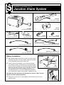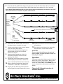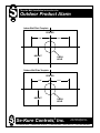
1
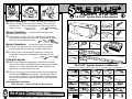
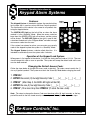
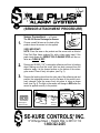
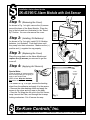
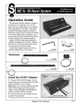
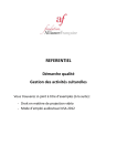
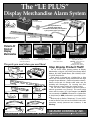
The “LE PLUS”
Display Merchandise Alarm System
SK-103LE
“LE” Alarm Module
SK-195
AC/DC Power Supply
Coupler
Use any combination of:
(SK-107LE) Splitter Boxes &
(SK-10106LE or SK-10112LE) “LE” Strip Alarms
in your system to protect up to 72 SKU’s.
SK-10106LE
“LE” Strip Alarm w/6 Ports
SK-10112LE “LE” Strip Alarm
w/12 Ports (not shown)
Protects All
Kinds of
Display
Merchandise
SK-107LE
“LE” Splitter Box
Drills
Camcorders
Protected with the
SKD-0453PC/LE
6’ (Coiled) Dual Sensor
(Collar Lasso & Rect.)
Protected with the
SK-904PC/LE
6’ (Coiled) Rectangular Sensor
Binoculars
Protected with the
SK-953PC/LE
6’ (Coiled)
Collar Lasso Sensor
The parts you need, when you need them!
SK-103LE
))) Extra Loud (((
External Horn
“LE” Alarm Module w/External Horn
“LE” Splitter Box w/6 Modular Plugs
SK-10112LE
“LE” Strip Alarm w/12 Modular Plugs
SK-1912
SK-10106LE
Rectangular Removal Tool
“LE” Strip Alarm w/6 Modular Plugs
SK-909
SK-195
SK-905
AC/DC Power Supply
Rectangular Sensor Adhesive Pads
Protected with the
SK-943P/LE - Lens (shown in inset)
6’ (Str. Wire) Tie Sensor
SKD-0443 - Camera with Lens
(shown above)
6’ (Coiled) Dual Sensor
(Rectangular & Tie Sensors)
Stop Display Product Theft!
SK-107LE
“LE” Alarm Module
SK-103XLE
Cameras & Lenses
Ant Sensor Adhesive Pads
SK-904PC/LE
SK-961PC/LE
6' (Coiled) Rectangular Sensor
6' (Coiled) Ant Sensor w/Tie-Wrap
SKD-0453PC/LE
SK-953PC/LE
6' (Coiled) Dual Sensor (Collar Lasso & Rect.)
6' (Coiled) Collar Lasso Sensor
The “LE PLUS” Alarm System protects all Display
Merchandise, using the (SK-103LE) Kord Kontrol Alarm
Module, SK-103LE Splitter Boxes, (SK-10106LE) & (SK10112LE) Strip Alarms.
Each sensor is plugged into a Splitter Box or Strip
Alarm and connected to display merchandise with high
strength “Super Adhesive”, (safe for all product surfaces).
Sensors come with 6 ft. flexible coiled cable, and are
available with Rectangular, Tie, Lassoing and Dual
Sensor Ends to protect virtually any display product.
The “LE PLUS” Alarm System is the first system to
take the guesswork out of security! This one-of-a-kind
sensor with its unique “LE” Light changes from WHITE
(not connected) to GREEN (connected to a Splitter Box
or Strip Alarm) to RED (connected to your display product).
Ideal security for Radios, Telephones, TV’s and VCR’s
as well as Power Tools, this sensor VISUALLY tells sales
associates, security personnel and customers, “I am
Working”.
SE-KURE CONTROLS,® INC.
3714 Runge Street ■ Franklin Park, IL 60131 ■ (847) 288-1111 ■ Toll Free 1-800-322-2435 ■ Fax (847) 288-9999
Rev. 1/27/99
©1999 Se-Kure Controls®, Inc.
SCI-9629
Fig. 6
Installation Instructions for the
Fig. 7
“LE PLUS” System Parts & Accessories
Fig. 5
Sensor Connections: – To Lenses (SK-943 Series Lens Sensor)
12. Insert the Tie-Wrap into the Lens Sensor as shown in Fig. 5, and wrap it
around the lens. Pull the Tie-Wrap tight, and cut off the excess with wire
SK-943
cutters or scissors.
SK-943T Tie-Wrap
Tie Sensor
SK-195
AC/DC Power Supply
SK-109
Extra Telephone “Shunt Plug”
SK-947-10
10' (Str. Wire) “LE” Extension w/Coupler
SK-110
Extra Key for Alarm Module
Sensor Connections:
– To Cameras with Removable Lenses
(SKD-0443 Series Dual Sensor)
13. The Dual Sensor, (shown in Fig. 6) is a combination of the Rectangular
Sensor and the Lens Sensor for cameras with removable lenses. Follow
Steps 9 thru 12 for installation procedures.
SKD-0443
SK-103LE
“LE” Alarm Module
Dual Sensor
Sensor Connections: – (SK-953 Series Collar Lasso Sensor)
14. The Collar Lasso Sensor has a wire connector that loops around the
SK-1912
Rectangular Removal Tool
SK-99-623
Strip Clips
SK-943T
Tie Wrap
product and plugs back into itself using a telephone modular plug.
SK-10106LE
“LE” Strip Alarm w/6 Ports
15. The Collar “Lasso” can be installed onto products be “Lassoing” any
SK-107LE
“LE” Splitter Box w/6 Modular Ports
SK-1712
Round Removal Tool
enclosed part of the product and plugging this module back into itself,
SK-953
(see Fig. 7).
SK-10112LE
“LE” Strip Alarm w/12 Ports
Collar Lasso Sensor
Testing the System:
16. With all sensors plugged into Splitter Boxes or Strip Alarms, and Shunt
SKP-200T
Wire (Tele. Plug) Removal Tool
Plugs in all unused Ports, the GREEN light on the front of the Alarm Module
should be “out”. Turn the Alarm Module key “Counter Clockwise” to the
“ON” position. The Alarm should remain silent.
15. Remove (1) plug from a Sensor Port and the alarm should (((sound))) with
that sensor port’s GREEN indicator light “ON”. This indicates an “open circuit”. Turn the key “Clockwise” to the “OFF” position, Re-Install the plug in
the sensor port, and turn the “Counter Clockwise” back to the “ON” position
and remove.
THE ALARM IS NOW OPERATING!
NOTE: For Safety. . . Cables Should Be 18" Above the Floor.
Rev.4/10/97
©1997 Se-Kure Controls,® Inc.
“LE PLUS” System Sensors & Adhesives
– Available in Standard 6' Cable Lengths - (PC/LE - Coiled) & (P/LE - Straight Wire) –
SK-902
1" x 1" Bug Sensor
SK-904
Rectangular Push-N-Go Sensor
SK-925
Serial Port Sensor
SK-927
Parallel Port Sensor
SK-940
Rect. (Micro Switch) Sensor
SK-943
Tie (No-See) Sensor
SK-953
Collar Lasso Sensor
SK-961
Ant Sensor
SK-965
Telephone Modular Sensor
SK-997
Pneumatic (Air Tool) Sensor
SK-998
Microphone Sensor
SKD-0404
Dual- Rectangular & Rectangular
SKD-0443
Dual- Rectangular & Tie Sensor
SKD-0453
Dual- Rect. & Collar Lasso
SKD-0461
Dual- Rect. & Ant Sensor
SKD-0465
Dual- Rect. & Tele. Modular
SKD-0425
Dual- Rect. & Serial Port Sensor
SKD-6161
Dual- Ant Sensor & Ant Sensor
SKD-6163
Dual- Ant & Mini Phone Modular
SKD-6165
Dual- Ant & Tele. Modular
SK-905
Rectangular
Adhesive
Pad
SK-906
Bug Sensor
Adhesive
Pad
SK-908
Tie Sensor
Adhesive
Pad
SK-909
Ant Sensor
Adhesive
Pad
SK-909NP
Neopreme
Ant Sensor
Adhesive Pad
SCI-9568
Se-Kure Controls, Inc.
®
3714 Runge St. • Franklin Pk., IL 60131 • 1-(800) 322-2435 • Fax: (847) 288-9999
1" x 2"
1" x 1"
11/4" x 1"
/16" x 11/16"
7
/16" x 11/16"
7
SK-103LE
Key Switch
Circuit Test Light
“LE” Alarm Box
Battery Installation:
1. Insert the key into
the “LE” Alarm
Box and turn it
“Clockwise” to the
“OFF” position.
Splitter Box
Connection
(Coupler)
AC/DC
Adapter
Connection
Alarm Box Screws
Splitter Box
Connection
(Coupler)
SK-109
“Shunt Plug”
2.
With a Standard Blade Screw Driver, remove the (4) four screws around the
base of the “LE” Alarm Module. Make sure the key is in the “OFF” position,
and lift off the cover.
3.
Install (2) two new 9-volt Alkaline, (such as Duracell)
batteries, (not included) inside the “LE” Alarm Box
by first positioning them on the connectors attached
to the circuit board and then pushing them firmly
into place, as shown in Fig. 1 to the right). The
Power Test Light (yellow) should flash indicating
that the power is on. This light will flash every 15
seconds indicating that the batteries are in good
working condition and the power is supplied to the unit.
Fig. 1
Note: When the yellow light flashes and simultaneously the horn “chirps”
twice the batteries need to be replaced immediately.
5.
Replace the cover onto the “LE” Alarm Module and Re-Install the (4) four
screws around the base.
Connect the (SK-195) AC/DC Power Supply to the jack on the rear of the
“LE” Alarm Module. Be sure to insert the plug fully into the jack! Plug the
other end of the AC/DC Power Supply into a standard 110-115v AC wall
outlet.
Note: If NO BATTERIES ARE INSTALLED, the yellow light will flash and
simultaneously the alarm horn will “chirp” twice until the batteries are
installed or the power is disconnected.
Splitter Box & Strip Alarm Connections:
6. Plug a Splitter Box or Strip Alarm into the Splitter Box Connector located at
Coupler Port
(for Additional Splitters & Strips Only)
DO NOT USE AS A SENSOR PORT
Sensor Connections: – To Splitter Boxes & Strip Alarms
8. Remove and SAVE the “Shunt Plug” from a Sensor Port, (see Fig. 2 above).
Insert a sensor’s modular plug into that port. Repeat this procedure until
all sensors have been plugged in. All ports should have either a “Shunt
Plug” or a Sensor with a lit GREEN light plugged into it.
Sensor Connections: – To Product
(SK-904 Series Sensors)
9. Choose a small flat area on the back of the product where the sensor is to
be applied.
VERY IMPORTANT!
NOTE: Clean the area on the product and the sensor with
Alcohol Prep Pads. Wipe these surfaces DRY with a clean
paper towel. If the paper towel shows dirt, REPEAT THIS
CLEANING STEP until the surfaces are CLEAN & DRY!
Remove the “Shunt Plug” from the Coupler Port of the first Splitter or Strip,
and connect the 2nd Splitter or Strip to the Coupler Port of the 1st.
Clean &
Wipe Dry
10. Remove an SK-905 (1" x 2") Rectangular Adhesive Pad from its backing
sheet. Apply the adhesive pad to the bottom of the sensor, making sure
that the center hole of the adhesive lines up with the plunger on the bottom
of the sensor. (See Fig. 3 below).
11. Remove the backing sheet from the other side of the adhesive pad and
position the Rectangular Sensor over the flat area of the product previously
cleaned. Press the sensor firmly into place to insure a proper bond, (as
shown in Fig. 4 below). The light on the sensor will change to RED when
the sensor is applied correctly to the product
Fig. 3
SK-905
the end of the Alarm Box cable, (see the illustration at the top of the page).
7.
Fig. 2
Power
Test
Light
Note: The key cannot be removed when is is in the “OFF” position.
4.
Sensor Ports w/Lights
Rectangular
Adhesive Pad
Remove
Adhesive
Backing
Fig. 4
Fig. 6
Installation Instructions for the
Fig. 7
“LE PLUS” System Parts & Accessories
Fig. 5
Sensor Connections: – To Lenses (SK-943 Series Lens Sensor)
12. Insert the Tie-Wrap into the Lens Sensor as shown in Fig. 5, and wrap it
around the lens. Pull the Tie-Wrap tight, and cut off the excess with wire
SK-943
cutters or scissors.
SK-943T Tie-Wrap
Tie Sensor
SK-195
AC/DC Power Supply
SK-109
Extra Telephone “Shunt Plug”
SK-947-10
10' (Str. Wire) “LE” Extension w/Coupler
SK-110
Extra Key for Alarm Module
Sensor Connections:
– To Cameras with Removable Lenses
(SKD-0443 Series Dual Sensor)
13. The Dual Sensor, (shown in Fig. 6) is a combination of the Rectangular
Sensor and the Lens Sensor for cameras with removable lenses. Follow
Steps 9 thru 12 for installation procedures.
SKD-0443
SK-103LE
“LE” Alarm Module
Dual Sensor
Sensor Connections: – (SK-953 Series Collar Lasso Sensor)
14. The Collar Lasso Sensor has a wire connector that loops around the
SK-1912
Rectangular Removal Tool
SK-99-623
Strip Clips
SK-943T
Tie Wrap
product and plugs back into itself using a telephone modular plug.
SK-10106LE
“LE” Strip Alarm w/6 Ports
15. The Collar “Lasso” can be installed onto products be “Lassoing” any
SK-107LE
“LE” Splitter Box w/6 Modular Ports
SK-1712
Round Removal Tool
enclosed part of the product and plugging this module back into itself,
SK-953
(see Fig. 7).
SK-10112LE
“LE” Strip Alarm w/12 Ports
Collar Lasso Sensor
Testing the System:
16. With all sensors plugged into Splitter Boxes or Strip Alarms, and Shunt
SKP-200T
Wire (Tele. Plug) Removal Tool
Plugs in all unused Ports, the GREEN light on the front of the Alarm Module
should be “out”. Turn the Alarm Module key “Counter Clockwise” to the
“ON” position. The Alarm should remain silent.
15. Remove (1) plug from a Sensor Port and the alarm should (((sound))) with
that sensor port’s GREEN indicator light “ON”. This indicates an “open circuit”. Turn the key “Clockwise” to the “OFF” position, Re-Install the plug in
the sensor port, and turn the “Counter Clockwise” back to the “ON” position
and remove.
THE ALARM IS NOW OPERATING!
NOTE: For Safety. . . Cables Should Be 18" Above the Floor.
Rev.4/10/97
©1997 Se-Kure Controls,® Inc.
“LE PLUS” System Sensors & Adhesives
– Available in Standard 6' Cable Lengths - (PC/LE - Coiled) & (P/LE - Straight Wire) –
SK-902
1" x 1" Bug Sensor
SK-904
Rectangular Push-N-Go Sensor
SK-925
Serial Port Sensor
SK-927
Parallel Port Sensor
SK-940
Rect. (Micro Switch) Sensor
SK-943
Tie (No-See) Sensor
SK-953
Collar Lasso Sensor
SK-961
Ant Sensor
SK-965
Telephone Modular Sensor
SK-997
Pneumatic (Air Tool) Sensor
SK-998
Microphone Sensor
SKD-0404
Dual- Rectangular & Rectangular
SKD-0443
Dual- Rectangular & Tie Sensor
SKD-0453
Dual- Rect. & Collar Lasso
SKD-0461
Dual- Rect. & Ant Sensor
SKD-0465
Dual- Rect. & Tele. Modular
SKD-0425
Dual- Rect. & Serial Port Sensor
SKD-6161
Dual- Ant Sensor & Ant Sensor
SKD-6163
Dual- Ant & Mini Phone Modular
SKD-6165
Dual- Ant & Tele. Modular
SK-905
Rectangular
Adhesive
Pad
SK-906
Bug Sensor
Adhesive
Pad
SK-908
Tie Sensor
Adhesive
Pad
SK-909
Ant Sensor
Adhesive
Pad
SK-909NP
Neopreme
Ant Sensor
Adhesive Pad
SCI-9568
Se-Kure Controls, Inc.
®
3714 Runge St. • Franklin Pk., IL 60131 • 1-(800) 322-2435 • Fax: (847) 288-9999
1" x 2"
1" x 1"
11/4" x 1"
/16" x 11/16"
7
/16" x 11/16"
7
Troubleshooting the “LE” Alarm System
Key Systems (SK-103LE) or Keypad Systems (SK-103KLE)
1. Alarm Problems
Alarm on, no apparent reason:
• Verify that the sensor is properly secured to the product
• Make sure sensor is properly installed
• Sensors are properly plugged into ports
(All ports must have either a sensor or a shunt plugged in them)
All sensor lights must be red, if not, recheck attachment to product.
No Alarm
• Make sure batteries are installed and the AC/DC power supply is
plugged in.
2. Beeping
Single beep, ever 30 seconds
• Unit is disarmed, arm either by turning key on or by keying in the
proper code.
Double beep
• Indicates low batteries, replace batteries
3. Keypad System
Cannot activate or de-activate the alarm system
• Make sure you are using the correct code
(Press the star key [*] to clear the wrong code and key in the correct
code).
Se-Kure Controls,® Inc.
3714 Runge Street • Franklin Park, IL 60131 • 1-(800) 322-2435 • (847) 288-1111 • Fax: (847) 288-9999
Rev. 1/29/99
©1999 Se-Kure Controls,® Inc.
SCI-9630
Troubleshooting the “LE” Alarm System
Key Systems (SK-103LE) or Keypad Systems (SK-103KLE)
4. Light Problems
Green light on sensor does not go off
• Recheck attachment to the product
Green light on LE strip of splitter box is “on”
• Verify that the sensor or shunt are properly plugged in.
(If it is a shunt, verify that the wire is not broken).
No lights
• Make sure batteries are installed and the AC/DC power supply is
plugged in.
No lights on sensors
• Verify that the strip is plugged into the alarm unit.
No lights on a specific sensor
• Plug another sensor into at the same location
- If it lights up– Replace the original sensor.
- If no lights appear on the sensor once again and other
sensors on the same strip are lit– Make sure the socket is clean
without any foreign objects and that the connection pins extend in
the same manner as in other sockets.
Yellow light is not flashing
• Light should flash every 10-15 seconds, if it does not, replace the
(2) two 9 volt batteries.
If the problem is different from any mentioned above,
or if you cannot resolve the problem,
please call our Customer Service Department at 1-(800) 322-2435
Se-Kure Controls,® Inc.
3714 Runge Street • Franklin Park, IL 60131 • 1-(800) 322-2435 • (847) 288-1111 • Fax: (847) 288-9999
Rev. 1/29/99
©1999 Se-Kure Controls,® Inc.
SCI-9630
3 Step Instruction for
the L.E.D. Lights
L.E.D.
Lights
Circuit Test
Power Test
Step 1: The SK-103LE Alarm Module Lights
YELLOW- Power Test Light (at front left)
• If this light flashes every 15 seconds:
• If this light flashes and simultaneously
the horn sounds twice:
• If this light flashes and simultaneously
the horn sounds twice continually:
Batteries are good
Batteries need to be replaced
There are NO BATTERIEShorn will continue to chirp until installed
GREEN- Circuit Test Light (at front right)
• If this light is lit, this indicates an open circuit, and horn will sound if system is “ON”.
A Sensor, Strip or Splitter has been disconnected or a connection is not complete.
Step 2: Splitter Box & Strip Lights
GREEN- Sensor Port Lights
GREEN- Sensor Port Lights
• If this light is lit, and No Sensor is plugged into the port: Insert a “Shunt Plug”,
and re-set the alarm.
• If this light is lit, and a Sensor is plugged in to that port, the Sensor connected
to the port is disconnected or ajar from the product.
• If this light is dark: The Sensor is connected properly.
L.E.D. Lights Changes Color
Step 3: Sensor Lights
WHITE: Not Connected to a Splitter or Strip
GREEN: Not Connected to Product
RED:
Connected Properly
WHITE- If this light is not lit, it indicates that the sensor is Not Plugged In
GREEN- If this light is lit and GREEN, it indicates that the Sensor is connected
to a Splitter Box or Strip, but not connected properly to the product.
RED- If this light is lit and RED, it indicates that the Sensor is connected properly
to the product, and actively protecting the product.
Rev.4/10/97
Se-Kure Controls,® Inc.
3714 Runge St. • Franklin Pk., IL 60131 • 1-(800) 322-2435 • Fax: (847) 288-9999
©1997 Se-Kure Controls,® Inc.
SCI-9569
Features & Operating Instructions for
Keypad Alarm Systems
Features:
The Keypad System is intended to replace the mechanical key
lock system that is used on various Se-Kure Controls products.
The functionality of this device is the same for all products featuring the keypad device.
Green
LED Light
Red
LED Light
The GREEN LED Light on the left will be on when the alarm
module is in the “Stand-By” Mode. When the access code has
been input, the GREEN LED Light will not be on, and the system
will be armed. The RED LED Light on the right is used to indicate when the device is in the “Program Mode” and able to accept
new access codes from the user.
If the system has entered an alarm, you can enter your security
code on the keypad to place the system in a “Stand-By” Mode.
The Keypad System features a device called Auto-Arm. It is
intended to automatically arm the system after 4 minutes.
Operation of the Keypad Lock System:
When power is first applied to the device, it will use the factory de-fault code of 1,2,3,4. The user
should change this code as soon as possible. The system will accept the default code until a new
one has been entered.
Changing the Default Access Code:
Follow the steps below to change the access code as desired. The codes cannot contain the (*)
star or (#) pound symbols! The system must be in the “Stand-By” Mode before changing the code.
1.
2.
3.
4.
5.
PRESS #
ENTER the current (4) four digit Security Code: [____] + [____] + [____] + [____]
PRESS * (After Step 3, the RED LED Light will be ON).
ENTER the new (4) four digit Security Code: [____] + [____] + [____] + [____]
PRESS * (One more time) then PRESS # (To store the new code)
Note: The steps to change the Access Code must be done within (8) eight seconds, or the keypad will be reset to the last stored security code, and you will be required to repeat the steps.
Se-Kure Controls,® Inc.
3714 Runge Street • Franklin Park, IL 60131 • 1-(800) 322-2435 • (847) 288-1111 • Fax: (847) 288-9999
Rev. 3/20/02
©2002 Se-Kure Controls,® Inc.
SCI-9616
Battery Installation & Low Battery Alarm
(2) 9-volt Alkaline Batteries
Position batteries as shown and push firmly
onto printed circuit board.
Low Battery Power Alarm
Light will flash and alarm will “chirp”
when batteries need to be replaced.
Rev. 7/22/04
©2004 Se-Kure Controls,® Inc.
Se-Kure Controls,® Inc.
3714 Runge St. • Franklin Pk., IL 60131 • 1-(800) 322-2435 • (847) 288-1111 • Fax: (847) 288-9999
SCI-9760
(SENSOR ATTACHMENT PROCEDURE)
Clean & Wipe Dry
Sensor Connections: – to Product
1.
The SK-904 Series Rectangul;ar Sensor:
Choose a small flat area on the back of the
product where the sensor is to be applied.
VERY IMPORTANT!
NOTE: Clean the area on the product and the sensor with an Alcohol
Prep Pad. Wipe these surfaces Dry. with a clean paper towel. If the
paper towel shows dirt, REPEAT THIS CLEANING STEP until the surfaces are CLEAN & DRY!
2.
Remove an SK-905 (1"x2") rectangular adhesive pad from its backing
sheet. Making sure that the center hole has been removed from the
adhesive, apply it to the cleaned surface on the bottom of the rectangular sensor. Press it firmly into place, (see Fig. 3).
3.
Remove the backing sheet from the other side of the adhesive pad and
position the rectangular sensor over the flat area of the product previously cleaned. Press the sensor firmly into place to insure a proper
bond, (see Fig. 4). The light on the sensor will change to RED when the
sensor is applied correctly to the product.
SK-905
Fig. 3
Rectangular
Adhesive Pad
Fig. 4
Remove
this
adhesive
backing
Rev. 7/26/04
©2004 Se-Kure Controls,® Inc.
SCI-9762
SE-KURE CONTROLS,® INC.
3714 Runge Street • Franklin Park, IL 60131-1112
1-800-322-2435
Installation Instructions for the
Junction Alarm System
SK-10106J
6 Port Junction Splitter
SK-107J
Junction Box
SK-103KLE
LE Keypad Alarm Module
SK-1912
Bug Sensor Removal Tool
SK-109
Standard Shunt Plug
SK-195
AC/DC Power Supply
Strap for Ant Sensor
SK-96-1068
12" (Str. Wire) Mini Phone Sensor
SK-98-1014
12" Dual - Ant w/Strap & Mini Phone Sensor
SK-96-1069
12" (Str. Wire) Bug Sensor
SK-99-12J (12") SK-99-48J (48")
12" & 48" (Str. Wire) Extensions w/Mini Phone Connectors
Battery Installation:
1. With a Standard Blade Screw Driver, remove the (4) four screws
around the base of the “LE” Alarm Module. Make sure the alarm
is in the “Stand-By” position and lift off the cover.
2.
Install (2) two new 9-volt Alkaline, (such as Duracell) batteries,
(not included) inside the “LE” Alarm Box by first positioning them
on the connectors attached to the circuit board and then pushing
them firmly into place, as shown in Fig. 1 to the right). The Power
Test Light (yellow) should flash indicating that the power is on.
This light will flash every 15 seconds indicating that the batteries
are in good working condition and the power is supplied to the unit.
SK-103KLE
Keypad
Replace the cover onto the “LE” Alarm Module and Re-Install the (4) four screws
around the base.
Circuit Test Light
Power
Test
Light
AC/DC
Adapter
Connection
(back)
Note: When the yellow light flashes and simultaneously the horn “chirps” twice the
batteries need to be replaced immediately.
3.
SK-159J
Mini Shunt Plug w/Resister
Alarm Box Screws
(Coupler)
Fig. 1
4.
Connect the (SK-195) AC/DC Power Supply to the jack on the rear of the “LE” Alarm Module. Be sure to insert the
plug fully into the jack! Plug the other end of the AC/DC Power Supply into a standard 110-115v AC wall outlet.
Note: If NO BATTERIES ARE INSTALLED, the yellow light will flash and simultaneously the alarm horn will “chirp”
twice until the batteries are installed or the power is disconnected.
SK-10106J
6 Port Slatwall
Splitter
#1
#2
#3
#9
#10
Do Not Use
This Port
Leave the
SK-109
Shunt Plug
in this Port!
SK-159J
Mini Shunt Plug w/Resister (from Junction Splitter)
Coupler
48
"(
St SKr. W 99
ire -48
)E J
xte
ns
ion
s
SK-103KLE
LE Alarm Module
5.
6.
7.
8.
9.
SK-107J
Junction Boxes
Position the 6 Port ”Junction Splitter” on the side of
the slatwall closest to a standard 110v outlet.
Plug the Junction Splitter into the “Coupler” attached
to the (SK-103KLE) Alarm Module.
Remove an (SK-159J) Mini Shunt Plug from the
Junction Splitter, and plug a 48" (SK-99-48J)
Extension into that port.
Remove the Velcro backing from a (SK-107J)
Junction Box, and place it over the slot at the
beginning of the slatwall.
Plug the other end of the 48" Extension, (from the
Junction Splitter) into the side of the Junction Box,
and a 12" (SK-99-12J) Extension into the other side.
10. Each row should be connected with Junction Box 11.
12" Extension - Junction Box - 12" Extension etc. . .
Plug the (SK-159J) Shunt Plug (removed from the
Junction Splitter) into the last Junction Box in the row.
SK-99-12J
12" (Str. Wire) Extensions
12. Repeat this procedure for all rows as laid out by your
13.
store planogram.
Plug a sensor into the front port of a Junction Box
(Bug, Mini Phone, or Dual -Ant/Mini Phone).
Special Note:
This is a “Closed Circuit” System, and requires all
ports to be filled. You must have either a sensor or a
shunt plug in every port.
Operation:
The Slatwall Junction Alarm System operates in much the
same as the “LE PLUS” Alarm System... When a sensor
has been disturbed, the light on the sensor and the
Junction Box will flash “RED”, and the GREEN light on the
Junction Strip will flash to indicate which row has been
affected.
Follow the LE & Keypad Instructions for
additional information.
Se-Kure Controls,® Inc.
3714 Runge Street • Franklin Park, IL 60131 • 1-(800) 322-2435 • (847) 288-1111 • Fax: (847) 288-9999
Rev. 10/15/98
©1998 Se-Kure Controls,® Inc.
SCI-9619
Installation Instructions for the
Outdoor Product Alarm System
SK-903KB
Outdoor Product Alarm Module w/External Horn
SK-907KB
Outdoor Product Alarm Splitter
SK-195
AC/DC Power Supply
SK-947KB8
Outdoor Cable (Available in Combinations of 8') - [xx = 8, 16, 24, etc.]
SKP-416K
Security Screw Allen Wrench
SK-195
AC/DC
Power supply
Installation Instructions:
SK-109KB
Terminator Loop
Ground (GREEN)
(connect eyelet to
center screw on
standard outlet plates)
Special Note: Make all connections before installing
batteries and connecting the AC/DC Power Supply.
SK-903KB
Outdoor Product
Alarm w/Keypad &
External Horn
Indoors:
1. Screw the Alarm Module’s Green Ground Wire to the
ground screw located on the center of a grounded 110v AC
outlet cover plate, and plug the AC/DC Power Supply into
the outlet. (Hold off until the battery step to plug the Power
Supply into the Alarm Module).
Dry Contacts
(can handle up to 24v)
1 Amp
2. Attach an (SK-947KB) Outdoor Cable to the end of the
Alarm Module Cable, and extend it Outdoors.
Outdoors:
3. Connect the cable extending from indoors to the
(SK-907KB) Outdoor Splitter. (The Splitter can be mounted
to a wall with #10 screws).
Do not allow Splitter or Connectors
to remain in standing water.
SK-109KB
Terminator Loop
SK-947KB
Outdoor Cable
SK-947KB
Outdoor Cable
SK-907KB
Outdoor Splitter
SK-109KB
Terminator Loop
Outdoor Display
Products
SK-109KB
Terminator Loop
Outdoor Display
Products
SK-947KB
Outdoor Cable
SK-907KB
Outdoor Splitter
SK-109KB
Terminator Loop
Outdoors: (continued)
4. Connect a (SK-947KB) Outdoor Product Cable to the (SK-907KB) Outdoor Splitter.
5. Pass the cable(s) through an enclosed area of each product, (such as spokes, or steering wheels) to protect all the display merchandise in the line, as shown above.
6. Thread the end of an (SK-947KB) Outdoor Cable
through the loop of a (SK-109KB) Terminator Loop, and
Lasso an enclosed area of the last product in line by
connecting the Terminator Loop and Cable Connector.
Last
Outdoor
Display
Products
7. Repeat the procedure for the other side of the
(SK-907KB) Outdoor Splitter.
SK-109KB
Terminator Loop
Last Outdoor
Display Products
Note: If the other side of the Splitter is not in use, a Terminator
Loop needs to be in that connection to create a “Closed Circuit” in
the system.
Battery Installation:
8. Remove the (4) Security Screw from
around the base of the Alarm Module with
the (SKP-416K) Security Allen Wrench.
Remove Security
Screws
9. Lift and remove the cover of the
(SK-903KB) Alarm Module.
10. Install (2) 9-v Alkaline batteries as
shown at right, and push firmly onto the
printed circuit board.
11. Replace the cover and the (4) security screws, and then plug in the AC/DC Power Supply.
Note: The cover security screws must be installed and tightened to prevent the alarm from sounding.
Low Battery Power Alarm
Low Battery Light will (((flash))) and Alarm will “CHIRP” when
batteries need to be replaced.
(When replacing batteries, refer to the Keypad Operating
Instructions to place the system in the “Stand-By” Position before removing security screws).
Se-Kure Controls,® Inc.
3714 Runge Street • Franklin Park, IL 60131 • 1-(800) 322-2435 • (847) 288-1111 • Fax: (847) 288-9999
Rev. 6/17/99
©1999 Se-Kure Controls,® Inc.
SCI-9615
Thru-the-Wall Installation Instructions for
Outdoor Product Alarm
Connector
Ring Side
Of Cable
Faces Out
To
SK-907KB
Outdoor
Product
Alarm
Splitter
SK-947KB-8
8' Outdoor
Cable
Assembly
ole
1" H gh
u
thro ll
Wa
Wall
e
Plat
Slit
Exte
rior
Wal
l
6"
to 12
"
Slit
Inte
rior
Wall Plate Template
(see back)
Installation:
1. Use the Wall Plate Template to locate
and mark the holes on the wall.
2. Drill the center 1" hole thru the wall.
3. Pass the end of the cable with the
Connector Ring through the wall to the
exterior of the building.
To
SK-903KB
Outdoor
Product
Alarm
Module
4. Caulk the hole around the cable.
5. Flex the wall plate to get the cable
through the slit to the center of the plate.
6. Fasten the wall plates to the walls with
the appropriate fasteners.
7. To weather seal, caulk the wall plate slit.
DO NOT CUT & REWIRE THE CABLE!
Se-Kure Controls,® Inc.
web: www.se-kure.com
e-mail: [email protected]
3714 Runge Street • Franklin Park, IL 60131 • 1-(800) 322-2435 • (847) 288-1111 • Fax: (847) 288-9999
Rev. 5/20/99
©1999 Se-Kure Controls,® Inc.
SCI-9637
Thru-the-Wall Installation Instructions for
Outdoor Product Alarm
Indoor Wall Plate Template
CENTER
1-5/8"
1-5/8"
HEIGHT
1 INCH
HOLE
Outdoor Wall Plate Template
CENTER
1-5/8"
HEIGHT
1-5/8"
1 INCH
HOLE
Se-Kure Controls,® Inc.
web: www.se-kure.com
e-mail: [email protected]
3714 Runge Street • Franklin Park, IL 60131 • 1-(800) 322-2435 • (847) 288-1111 • Fax: (847) 288-9999
Rev. 5/20/99
©1999 Se-Kure Controls,® Inc.
SCI-9637
Installation Instructions for the
SK-403/961C Alarm Module with Ant Sensor
Step 1: (Removing the Cover)
As shown in Fig. 1 at right, remove the (4) screws
around the base of the Alarm Module. Place the
key in the lock and turn (clockwise) to the “StandBy” Position. You can now remove the cover.
Step 2: (Installing 9V Batteries)
Fig. 1
Remove
the (4)
screws
around
the alarm
module
base.
As shown in Fig. 2 at right, install (2) 9V Alkaline
batteries, (not included). Push them down until
they snap onto their connectors. Make sure the (+)
positive and (-) negative line up properly.
Fig. 2
Step 3: (Replacing the Cover)
Place the cover back on the Alarm Module and
replace the (4) screws you removed to get the
cover off.
Step 4: (Applying Ant Sensors)
Tie-Wrap
Special Note:
SK-909
Ant Sensor
Adhesive
Clean the bottom of sensors and the
area on the product you are going to
apply it with Alcohol Pads.
While still wet, Wipe the Surfaces
Dry with a clean paper towel or rag.
• As shown in Fig. 3 at right, remove the backing
sheet from the adhesive and apply it to the sensor.
• Remove the other backing sheet and apply the
sensor to the clean and dry area on the palm.
• Pass the Tie-Wrap thru the slot in the Ant Sensor,
wrap it arount the Palm, and through the tie-wrap
locking mechanism. Cut off excess tie-wrap.
Ant
Sensor
Palm
Fig. 3
Se-Kure Controls,® Inc.
3714 Runge Street • Franklin Park, IL 60131 • 1-(800) 322-2435 • (847) 288-1111 • Fax: (847) 288-9999
Rev. 10/24/00
©2000 Se-Kure Controls,® Inc.
SCI-9677
SK-195
AC/DC Power Supply
SK-403/961C
Alarm Module w/Coiled Ant Sensor
Final Assembly & Operating Instructions:
Plug the AC/DC Power Supply into any standard 110v AC outlet, and the mini connector
into the back of the Alarm Module. (Make sure the key is in the (clockwise) Stand-By
Position).
The sensor must be securely attached so the plunger on the sensor is
depressed.
• If the Alarm sounds during the stallation, check the sensor to make sure that the
plunger on the sensor is placed against a solid flat surface on the merachandise.
Arm the System
• With light RED and properly attached, turn the key (counterclockwise) and
remove the key to arm the system. (Put the key in a safe location).
Re-Arming the System After An Alarm
• After an alarm has been set off, insert the key in the Alarm Module and turn the key
(clockwise) to the Stand-By position.
• Clean & Dry the Ant Sensor and the area on the product where it is to be attached.
• Apply the sensor to the merchandise with a new SK-909 Ant Sensor Adhesive.
• If the sensor cable has been cut or damaged, call your Se-Kure Controls Customer
Service Representative for repair service.
Battery Testing
• Unplug the AC/DC Power Supply from the Alarm Module,
and press the “Battery Test Button.
• If the horn sounds, the batteries are ok.
• If the horn does not sound, or is weak, replace the
(2) 9V Alkaline Batteries.
Se-Kure Controls,® Inc.
3714 Runge Street • Franklin Park, IL 60131 • 1-(800) 322-2435 • (847) 288-1111 • Fax: (847) 288-9999
Rev. 10/24/00
©2000 Se-Kure Controls,® Inc.
SCI-9677