1
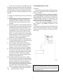
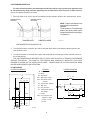
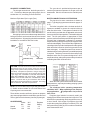
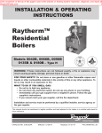
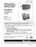
INSTALLATION
AND OPERATING
INSTRUCTIONS
Catalog No.: 2100.50V
Effective: 04-01-04
Replaces: 01-01-03
RaythermTM
Type H
RESIDENTIAL BOILERS
Models
0030B, 0042B, 0066B,0090B
0135B, 0180B
FOR YOUR SAFETY
Do not store or use gasoline or other flammable vapors and liquids or other combustible materials
in the vicinity of this or any other appliance. To do so may result in an explosion or fire.
WARNING: Improper installation, adjustment, alteration, service or maintenance can cause
property damage, personal injury or loss of life. Refer to the user's information manual provided
with this boiler. Installation and service must be performed by a qualified installer, service agency
or the gas supplier.
FOR YOUR SAFETY
WHAT TO DO IF YOU SMELL GAS
*Do not try to light any appliance.
*Do not touch any electrical switch; do not use any phone in your building.
*Immediately call your gas supplier from a neighbor's phone. Follow the gas supplier's
instructions.
*If you cannot reach your gas supplier, call the fire department.
THIS MANUAL SHOULD BE MAINTAINED IN LEGIBLE CONDITION AND KEPT ADJACENT TO THE BOILER OR IN A SAFE
PLACE FOR FUTURE REFERENCE.
P/N 240488
Contents
RECEIVING EQUIPMENT................................................................................. 3
GENERAL SPECIFICATIONS........................................................................... 3
INSTALLATION PROCEDURES........................................................................ 4
Code Requirements..................................................................................... 4
Mounting Base...........................................................................................4
ClearanceRequirments.................................................................................4
Combustion/Ventilation Air........................................................................... 4
Venting Connections................................................................................... 5
Vent Damper Installation.............................................................................. 7
Gas Supply Connections............................................................................. 11
Water Connections & System Piping............................................................ 11
Piping Diagrams..........................................................................................12
Electrical Wiring..........................................................................................15
Wiring Diagrams......................................................................................... 16
SERVICING PROCECURES.............................................................................. 23
General Locations of Controls.......................................................................23
Sequence of Operation................................................................................ 23
Start-Up Procedures.................................................................................... 24
Shut-Down Procedure.................................................................................. 26
Safe Shutdown Test.................................................................................... 28
Inspection Procedures................................................................................. 28
Repair Procedures.......................................................................................29
TROUBLE SHOOTING GUIDE........................................................................... 31
Adjustments/Replacements of Components...................................................33
REPLACEMENT PARTS LIST........................................................................... 34
CALIFORNIA PROPOSITION 65 WARNING: This product contains chemicals known to the State of California to
cause cancer, birth defects or other reproductive harm.
These instructions are provided to assure the proper installation and operation of Raypak boilers. Should questions
arise regarding the specifications, installation, operation or servicing of these boilers, we suggest that the local Sales
representative or the factory be consulted.
2
RECEIVING EQUIPMENT
Follow the installation instructions furnished with the vent
damper package. The plug-in connector can also be
used with power venters. Refer to the specific installation
instructions supplied by the power vent manufacturer.
On receipt of your equipment, visually check for
external damage to the carton. If the carton is damaged,
it is suggested that a note be made on the Bill of Lading
when signing for the equipment. Remove the boiler from
the carton, and if it is damaged, report the damage to
the carrier immediately. Be sure that you receive the
number of packages indicated on the Bill of Lading.
Claims for shortages and damages must be filed
with carrier by consignee.
Purchased parts are subject to replacement only
under the manufacturer's warranty. Debits for defective
replacement parts will not be accepted and defective
parts will be replaced in kind only per our standard
warranties.
When ordering parts, you must specify Model and
Serial Number of boiler. When ordering under warranty
conditions, you must also specify date of installation.
Raypak recommends that this manual be reviewed thoroughly before installing the boiler. If
there are any questions which this manual does not
answer, please contact your local Raypak representative.
SPECIFICATIONS AND DIMENSIONS
GENERAL SPECIFICATIONS
Raytherm hydronic boilers are design certified and
tested under the requirements of the American National
Standard, ANSI Z21.13. Each boiler has been constructed and pressure tested in accordance with the
requirements of Section IV of the American Society of
Mechanical Engineers Code, and factory fire tested.
The boilers are designed for indoor installation with a
built-in drafthood, and a built-in sub-base for combustible
flooring. Models are available with standing pilot,
or with intermittent ignition device (I.I.D.). The boilers are
equipped with the following components: water circulation pump, pressure relief valve, temperature/pressure
gauge, adjustable high limit switch, drain valve, fast
response temperature sensor, 40 VA transformer, pump
relay, vent thermal switch, flame roll-out switch, and
redundant combination gas valve. Two-stage gas valve
(50% firing on first stage) is standard on models
H-0090, H-0135 and H-0180.
The automatic ignition models and some standing
pilot models are provided with a plug-in connector that is
compatible with the Honeywell D80D vent damper. Similar type vent dampers made by other manufacturers, and
design certified by a nationally-recognized testing
agency, under the ANSI Z21.66 standards, may also be
used.
Fig. #8978.1
3
3. INSTALLATION PROCEDURES
CODE REQUIREMENTS
Installation must be in accordance with local
codes, or, in the absence of local codes, with the latest
editions of the National Fuel Gas Code, ANSI Z223.1,
and the National Electrical Code, ANSI/NFPA 70. In
Canada, installations must conform with the current
CAN/CGA B149.1 or .2 and the Canadian Electrical
Code Part 1 CSA C22.2 No.1. Where required by the
authority having jurisdiction, the installation must conform to American Society of Mechanical Engineers
Safety Code for Controls and Safety Devices for Automatically Fired Boilers, No. CSD-1.
CLEARANCE REQUIREMENTS
1) Minimum Clearances From Combustible Materials
Model Floor Front Back Right Left
No.
0030
0042 Comb. 4"
6"
6"
6"
0066
0090
0135 Comb. Alcove 6"
6"
6"
0180
Top Flue
Vent
16"
6"
16"
6"
2) A front clearance of at least 24" is recommended for
adequate service of burner-tray and controls.
MOUNTING BASE
Boiler should be mounted on a level surface. Each
boiler is designed with a built-in sub-base approved for
mounting the boiler on combustible flooring. Boiler
must NOT be installed on carpet flooring.
3) Except for carpeted flooring, boilers are certified for
installation on combustible floors.
4) For un-insulated hot water pipes, maintain a 2"
clearance, or consult local authority having jurisdiction.
COMBUSTION/VENTILATION AIR
WARNING: Air supply to the boiler room must not be
affected by mechanical exhaust vents located in other
parts of the house, such as kitchen or bathroom fans,
or attic blowers. Mechanical exhaust vents may create
a negative pressure condition in the boiler room that
can become a hazard of asphyxiation, explosion or fire.
CAUTION: Combustion air must not be contaminated
by corrosive chemical fumes which can damage the
boiler. Measures must be taken to prevent the entry of
corrosive chemical fumes to the combustion and ventilation air supply. Such chemicals include, but are not
limited to, chlorinated and/or fluorinated hydrocarbons
such as found in refrigerants, aerosol propellants, drycleaning fluids, degreasers, and paint removers. Other
harmful elements may come from bleaches, air fresheners, or mastics. Vapors from these types of products
can form corrosive acid compounds when burned in a
gas flame. The resulting acid condensate can damage
or substantially reduce the life of the heater. It may be
necessary to provide outside air directly to the heater in
order to avoid this problem.
Fig.# 8196
NOTE: The boiler should be located in an area where
water leakage will not result in damage to the area
adjacent to the appliance or to the structure. When
such locations cannot be avoided, it is recommended
that a suitable drain pan, adequately drained, be installed under the appliance. The pan must not restrict
air flow.
1) The boiler must be provided with adequate supply of
air for proper combustion and ventilation in accordance with Sec. 5.3, of the latest edition of the
National Fuel Gas Code, ANSI Z223.1, or applicable provisions of the local building codes.
In addition, the boiler shall be installed such that
the gas ignition system components are protected from
water (dripping, spraying, rain, etc.) during appliance
operation and service (circulator replacement, control
replacement, etc.)
4
2) When the boiler is installed in a confined space
such as a utility room or closet (Models 0030,0042
and 0066 only), where all air is supplied from inside
the building, the boiler room must be provided with
two openings, each one having a minimum net free
area, in square inches as follows:
Model
0030, 0042 & 0066
Location of the openings is the same as in the
previous case - that is, within 12" of the top, and within 12"
of the bottom of the enclosure. If horizontal ducts are
used, the area must be doubled and the duct area shall
not be less than the area of the openings they connect,
and in no case shall the smallest dimension be less than
3".
Sq. In. of Free Area
100
VENTING CONNECTIONS
These boilers have built-in drafthoods. Vent piping
the same size or larger than the drafthood outlet is
recommended; however, when the total vent height
(drafthood outlet to vent terminal) is at least ten (10)
feet, the vent pipe size may be reduced by one size only
as specified in Chapter 10 of the latest edition of the
National Fuel Gas Code, ANSI Z 223.1. As much as
possible, avoid long horizontal runs of vent pipe and too
many elbows. If installation requires horizontal runs, the
vent pipe must have a minimum of 1/4 inch per foot rise
and should be supported at not less than five foot
intervals. Maximum vent connector horizontal length
shall be 1-1/2 feet (18 inches) for each inch of connector
diameter as follows.
One opening shall be within 12" of the top, and the
other opening within 12" of the floor. If additional gas
appliances are installed in the same space, the total input
of all gas appliances installed in the same space, must
be considered in the calculation. Refer to Sec. 5.3.5 of the
latest edition of the National Fuel Gas Code for additional
requirements.
Model
30 & 42
66 & 90
135
180
Fig. #8198.0
If the boiler room is located against an outside wall
and air openings can communicate directly with the
outdoors, the two openings on the outside wall must
each have a net free area as follows:
Model
0030 & 0042
0066
0090
0135
0180
4"
5"
6"
7"
Max Horizontal
Length - FT
6'
7.5'
9'
10.5'
Gas vents supported only by the flashing and extending above the roof more than five feet should be securely
guyed or braced to withstand snow and wind loads. We
recommend use of insulated vent pipe spacer through the
roofs and walls.
For protection against rain or blockage by snow, the
vent pipe must terminate with a listed vent cap which
complies with the local codes or, in the absence of such
codes, to the latest edition of the National Fuel Gas
Code, ANSI Z 223.1.
The discharge opening must be a minimum of two
feet vertically from the roof surface and at least two (2)
feet higher than any part of the building within ten (10)
feet. Vent stack shall be at least five (5) feet in vertical
height above the drafthood outlet. The vent cap location
shall have a minimum clearance of four (4) feet horizontally from, and in no case above or below, unless a 4-foot
horizontal distance is maintained, from electric meters,
gas meters regulators and relief equipment.
NOTE: If louvers, grills or screens are used on the
openings, obtain the net free area requirements from
their supplier or manufacturer. If the design free area of
a louver is not known nor available, it shall be assumed
that wood louvers will have 20-25 percent free area and
metal louvers will have 60-75 percent free area as shown
in Sec. 5.3.5 National Fuel Gas Code.
3)
Vent Connector
Diameter
(Sq. In.) Net Free Area
12
18
24
35
45
5
The weight of the vent stack or chimney must not rest
on the boiler's drafthood. Support must be provided in
compliance with applicable codes. The boiler top and
drafthood must be readily removable for maintenance and
inspection. Vent pipe should be adequately supported to
maintain proper clearances from combustible construction.
Type "B" double-wall (or equivalent vent pipe is
recommended. However single-wall metal vent pipe may
be used as specified in the latest edition of the National
Flue Gas Code ANSI Z 223.1.
Listed Cap
Lowest Discharge
Opening
Listed Gas Vent
X
Fig.# 8191
12
WARNING: These boilers must not be connected into
any portion of mechanical draft systems operating
under positive pressure. To do so may cause the flue
products to be discharged into the living space causing
serious health injury.
Roof Pitch is X/12
H - Minimum Height from
Roof to Lowest
Discharge Opening
Roof Pitch
Flat to 6/12
6/12 to 7/12
Over 7/12 to 8/12
Over 8/12 to 9/12
Over 9/12 to 10/12
Over 10/12 to 11/12
Over 11/12 to 12/12
Over 12/12 to 14/12
Over 14/12 to 16/12
Over 16/12 to 18/12
Over 18/12 to 20/12
Over 20/12 to 21/12
For connections to gas vents or chimneys, vent
installations shall be in accordance with Part 7, Venting
of Equipment, of the National Fuel Gas Code, ANSI
Z223.1, or applicable provisions of the local building
codes.
H (Min. Ft.)
1.0
1.25
1.5
2.0
2.5
3.25
4.0
5.0
6.0
7.0
7.5
8.0
COMMON VENTS
Manifolds that connect more than one
boiler to a common chimney must be
sized to handle the combined load.
Consult available guides for proper
sizing of the manifold and the chimney.
At no time should the area be less than
the area of the largest outlet.
Fig. #9001
6
At the time of removal of an existing boiler, the
following steps shall be followed with each appliance
remaining connected to the common venting system
placed in operation, while the other appliances remaining connected to the common venting system are not in
operation.
VENT DAMPER INSTALLATION
LOCATION
The vent damper supplied with each boiler must be
located in the vent so that it serves only the appliance for
which it is intended.
If improperly installed, a hazardous condition,
such as an explosion or carbon monoxide poisoning, could result. Make certain that it is mounted in an
accessible location at least 6 in. (152.4 mm) from any
combustible material or the heat exchanger and that the
position indicator is in a visible location.
The vent damper must be installed at the appliance drafthood, and without modification of the
drafthood.
To connect the vent damper wiring to the boiler wiring,
remove the jumper from the circuit plug. (See wiring
diagram) Connect the damper circuit plug to the boiler
circuit plug.
(a) Seal any unused openings in the common venting
system.
(b) Visually inspect the venting system for proper size
and horizontal pitch and make sure there is no
blockage or restriction, leakage, corrosion and
other deficiencies which could cause an unsafe
condition.
(c) Insofar as is practical, close all building doors and
windows and all doors between the space in which
the appliances remaining connected to the common venting system are located and other spaces
of the building. Turn on clothes dryers and any
appliance not connected to the common venting
system. Turn on any exhaust fans, such as range
hoods and bathroom exhausts, so they will operate
at maximum speed. Do not operate a summer
exhaust fan. Close fireplace dampers.
(d) Place in operation the appliance being inspected.
Follow the lighting instructions. Adjust thermostat
so appliance will operate continuously.
e) Test for spillage at the drafthood relief opening
after 5 minutes of main burner operation. Use the
flame of a match or candle, or smoke from a
cigarette, cigar or pipe to visually check spillage.
(f) After it has been determined that each appliance
remaining connected to the common venting system properly vents when tested as outlined above,
return doors, windows, exhaust fans, fireplace
dampers and any other gas burning appliance to
their previous conditions of use.
(g) Any improper operation of the common venting
system should be corrected so that the installation
conforms with the latest edition of the National Fuel
Gas Code, ANSI Z 223.1. When resizing any
portion of the common venting system, the common venting system should be resized to approach
the minimum size as determined using the
appropriate tables in Chapter 10 and in Appendix
G
of the National Fuel Gas Code, ANSI Z 223.1
and
CAN/CGA - B149.1 - B149.2.
Fig. #8642
WARNING: Read carefully and follow the installation
instructions furnished with the vent damper package.
Failure to follow these instructions can cause asphyxiation, explosion or fire.
7
MOUNTING
On vertical vents, the vent damper may be mounted with the actuator in any position. On horizontal vents,
do not mount the actuator either directly above or directly below the vent pipe; mount the vent damper actuator
to the side of the vent.
The vent damper is set up for a continuous pilot system. If the vent damper is installed on a system with an
Intermittent Pilot or Hot Surface Ignition the energy savings of the vent damper can be improved by plugging the hole
in the vent damper blade using the knockout plug, Part No. 105612R, provided in the parts envelope.
Hole in Vent Damper Blade
Closed Position
Fig. #8994
DO NOT plug the hole if installing the vent damper on a continuous pilot system as this will create a
hazardous condition.
1K
1K1
D80
MOTOR
N.C.
1K2
Fig. #8183.0
INSTALLING THE VENT DAMPER IN HORIZONTAL
& VERTICAL VENT.
3
BLUE
YELLOW
4
C.
1K3
2
1
ORANGE
N.O.
BLACK
END
SWITCH
CABLE
Fig. #152323
D80D GENERAL WIRING DIAGRAM
INSTALL THE VENT DAMPER TO SERVICE ONLY THE SINGLE APPLIANCE FOR WHICH IT IS INTENDED.
IF IMPROPERLY INSTALLED, A HAZARDOUS CONDITION, SUCH AS AN EXPLOSION OR CARBON
MONOXIDE POISONING, COULD RESULT.
8
VENT DAMPER OPERATION
For safe, efficient operation, the vent damper and all flue-product-carrying areas of the appliance must
be checked annually, with particular attention given to deterioration from corrosion or other sources.
Check vent damper operation as follows:
1. When the boiler is off, check that the vent damper position indicator points to the closed position, below.
DAMPER POSITION
INDICATOR
DAMPER POSITION
INDICATOR
NOTE: To place vent damper in the
open position to allow burner
operation:
Turn the power off. Turn the damper
blade to fully open position (arrow
facing same direction as vent pipe).
Turn power on.
DAMPER OPEN
DAMPER CLOSED
Fig. # 8181.0
VENT DAMPER POSITION INDICATOR
2. Turn the thermostat or controller up to call for heat and check that the vent damper indicator points to the
open position, below.
3. Turn the thermostat or controller down again and check that the vent damper position indicator returns to
the closed position.
THE VENT DAMPER MUST BE INSPECTED AT LEAST ONCE A YEAR BY A TRAINED, EXPERIENCED
SERVICE TECHNICIAN. THE NAME OF THE PERSON WHO ORIGINALLY INSTALLED YOUR VENT
DAMPER IS SHOWN ON THE INSTALLATION LABEL. DAMPER MUST BE IN OPEN POSITION WHEN
BOILER MAIN BURNERS ARE OPERATING.
FLAIR DAMPER
SYSTEM SCHEMATIC
LEGEND
M - Damper motor
R - Relay
ES - End switch
SS1 - N/C Safety switch
SS2 - N/O Safety switch
contacts
TR - Transformer 120/24V
HL - High limit
GV - 24V gas valve*
TH - Thermostat, heating,
low voltage
J - Jumper
Note: Circuit shown with
damper in closed
position, no call
for heat.
R
R2
SC
SS2 ES
SS 1
R1
JUMPER
M
1
2
4
3
HL
GV
24 VAC
LADDER DIAGRAM
24
V
AC
R
TH
2
4
GV
3
SS
J
1
HL
ES
SS
M
2
R
2
SC
R1
TH
TR
L
120 VAC
60Hz L
1
2
Fig. #9002
Fig. #9003
9
CONNECTION DIAGRAM
10
GAS SUPPLY CONNECTIONS
The inlet gas connection of the boiler gas valve is
1/2". Provide an adequate gas piping supply line no
smaller than 1/2", according to the chart below:
The gas valve is provided with pressure taps to
measure gas pressure upstream of the gas valve and
downstream which is the same as the manifold pressure.
Maximum Equivalent Pipe Length (Feet)
WATER CONNECTIONS & SYSTEM PIPING
The pipe size for water connections is shown on
page 3. Typical piping systems are shown on pages 12
to 14.
The boiler is supplied with a circulator and built in
bypass as standard to ensure the required minimum
water flow in the boiler. The bypass on models H-0135
and H-0180 is provided with an adjustable valve that is
factory-set in the full open position. The handle is shipped
loose. The full open position is appropriate for most
systems, and ensures adequate flow through the boiler.
If system flow is inadequate, (indicated by excessive
temperature drop through the system) the bypass valve
can be throttled slightly. Care must be taken against over
-throttling which may lead to inadequate flow through the
boiler and boiler harmonics (a humming sound from the
heat exchanger). If adequate system flow cannot be
obtained without causing harmonics, an additional pump
is required. The factory-mounted circulator will provide
adequate water flow for systems designed at a 20°F
temperature drop, and system pressure drop or head not
exceeding that which is shown below.
Gas piping must have a sediment trap ahead of the
boiler gas controls, and a manual shut-off valve located
outside the jacket. All gas piping should be tested after
installation in accordance with local codes.
Manual
Valve
Union
Sediment Trap
Gas Valve
Fig. # 8192.0
CAUTION: The boiler and its manual shut-off valve must be
disconnected from the gas supply during any pressure
testing of that system at test pressures in excess of 1/2 psig
(3.45 KPA). Dissipate test pressure in the gas supply line
before reconnecting the boiler and its manual shut-off valve
to gas supply line. FAILURE TO FOLLOW THIS PROCEDURE MAY DAMAGE THE GAS VALVE. OVER PRESSURED GAS VALVES ARE NOT COVERED BY WARRANTY. The boiler and its gas connections shall be leak
tested before placing the appliance in operation. Use soapy
water for leak test. DO NOT use open flame.
NOTE: Do not use teflon tape on gas line pipe thread.
A flexible sealant suitable for use with Natural and
Propane gases is recommended.
These boilers are also certified to operate on propane
gas, when equipped with the combination gas valve and
orifices (pilot and main burners) sized for propane gas.
GAS PRESSURE
Inches
Min.
Natural
7.0
Propane
12.0
W.C.
Max.
14.0
14.0
Regulator
Setting
3.5
11.0
11
When the total system head exceeds the available
head pressures, a primary/secondary pumping system
is recommended.
The minimum boiler operating temperature
should be 105°F. When operating at low temperature applications,
T (temperature rise) must be
20°F or less.
Propylene glycol solution is commonly used in the
heating system when freeze protection is required. This
will affect the system design and pump performance. As
a rule of thumb, 50% solution of propylene glycol will
require the system flow (GPM) to increase by 14%, and
the system head (Ft/Wtr) by 23% in order to maintain the
same heat transfer load.
Systems with multiple zones may require an additional circulator. Consult manufacturer's data for valve pressure
drops. When an indirect water heating system is used, it is recommended that a separate circulator be installed
to meet the required flow and pressure drop conditions of the indirect water heater.
We recommend that the make-up water from the cold water line have a check valve, gate valve, and feedwater
regulator set at 12 psig. Install unions and gate or ball valves at inlet and outlet connections at the boiler to facilitate
servicing.
The pressure relief valve is mounted on the boiler and must be piped to a drain. We recommend that all high
points be vented and that purge valves be installed. A boiler installed above radiation level must be provided with
a low water cut-off device. See page 22 for wiring hook-up. The boiler, when used in connection with a refrigeration
system, must be installed so that the chilled medium is piped in parallel with the boiler with appropriate valves to
prevent the chilled medium from entering the boiler.
The boiler piping system of a hot water heating boiler, that is connected to heating coils located in air handling
units where they may be exposed to refrigerated air circulation, must be equipped with flow control valves or other
automatic means to prevent gravity circulation of the boiler water during the cooling cycle.
A diaphragm expansion tank should be installed in the return line. A typical 8" -diameter expansion tank can
be used on models H-0030, H-0042, and H-0066, and an 11"-diameter expansion tank can be used on models H0090, H-0135 and H-0180. Consult tank manufacturer for correct sizing.
PIPING DIAGRAMS
AIR
VENT
AIR
SCOOP
DIAPHRAGM
EXPANSION TANK
FEED
VALVE
PIPE PRESSURE
RELIEF VALVE
TO DRAIN
COLD
WATER
INLET
HEATING UNITS
SINGLE-ZONE PIPING
Fig.# 8997.1
12
AIR
VENT
AIR
SCOOP
FEED
VALVE
DIAPHRAGM
EXPANSION
TANK
PIPEPRESSURE
RELIEF VALVE
TO DRAIN
ZONE
VALVES
COLD
WATER
INLET
HOT WATER
SUPPLY
HEATING UNITS
CIRCULATOR
COLD
WATER
SUPPLY
Fig.# 8998.1
ZONE HEATING WITH INDIRECT DOMESTIC
HOT WATER SUPPLY
13
AIR
VENT
12" MAX.
AIR
SCOOP
FEED
VALVE
DIAPHRAGM
EXPANSION
TANK
PIPE PRESSURE
RELIEF VALVE
TO DRAIN
CIRCULATORS
COLD
WATER
INLET
HEATING UNITS
Fig. #8999.1
MULTIPLE ZONES WITH CIRCULATORS
AIR
VENT
AIR
SCOOP
FEED
VALVE
DIAPHRAGM
EXPANSION
TANK
PIPE PRESSURE
RELIEF VALVE
TO DRAIN
COLD
WATER
INLET
ZONE
VALVES
HEATING UNITS
Fig. #9000.1
MULTIPLE ZONES WITH ZONE VALVES
14
ELECTRICAL WIRING
The electrical power supply requirement for these
boilers is 115 volts, 60 Hz. Field wiring connections and
electrical grounding must comply with the local codes,
or in the absence of local codes, with the National
Electrical Code, ANSI/NFPA 70-1987. Provide a separate fused circuit from the main electrical panel to the
boiler, and a disconnecting means within sight of the
boiler.
Remove the control box cover and make the power
supply connections in the field wiring compartment.
(See general location of controls drawing on page 23).
The pump is supplied and factory-wired to operate with
the boiler. The "TH" wire leads are for the room thermostat or zone valve connections.
The room thermostat should be installed in accordance
with the manufacturer's instructions. The thermostat heat
anticipator should be set at 1.0 ampere (automatic
ignition) and 0.60 ampere (standing pilot) for single- zone
installations. For multi-zone applications, the heat anticipator setting should be based on the ampere load in the
thermostat circuit.
NOTE: If it is necessary to replace any of the original
wiring, it must be replaced with 105°C wire or its
equivalent, except 150° C black wire must be replaced
with 150°C wire or its equivalent. See Wiring Diagram Key
for 150°C wire indication.
WIRING DIAGRAM KEY
Fig.# 8096.2
15
WIRING DIAGRAM KEY
16
17
18
WIRING DIAGRAM: Single-Zone Taco Valve
Fig. # 2228e
WIRING DIAGRAM: Dual-Zone Taco Valve
Fig. # 2229e
NOTE: Maximum three (3) zone valves per one (1) 40 VA transformer.
WIRING DIAGRAM: Dual-Zone Honeywell Valve
Fig. # 2230e
NOTE: Maximum five (5) zone valves per one (1) 40 VA Transformer.
19
WIRING DIAGRAM: System with (3) Zone Pumps
Fig. #2232e
NOTE: Check VA rating of each relay coil. Total load must not exceed VA rating of transformer.
WIRING DIAGRAM: Power Vent System w/ Zone Valve
Fig. #2233e
Fig. #2234e
20
WIRING DIAGRAM: Primary/Secondary Pumping System
Honeywell Zone Valve
Fig. #2223.2e
21
WIRING DIAGRAM: Standing Pilot With Low Water Cut-off Device
Fig. # 2223.1e
Note: Low water cut-off (LWCO) and system switch supplied by others.
WIRING DIAGRAM: IID Units With Low Water Cut-off Device
Fig. # 2357E
Note: Low water cut-off (LWCO) and system switch supplied by others.
22
4. SERVICING PROCEDURES
GENERAL LOCATION OF CONTROLS
CIRCULATOR
VENT SENSOR
CONTROL BOX COMPONENT
LOCATIONS MODELS 135 & 180
2-Stage Controller
BYPASS VALVE
(MODELS 135 & 180 ONLY)
BYPASS LINE
TEMPERATURE
AND PRESSURE GAUGE
Relay
2-STAGED CONTROLLER
(MODEL 90 ONLY)
PRESSURE
RELIEF VALVE
RELAY
ADJUSTABLE
HIGH LIMIT
FIELD WIRING
COMPARTMENT
FastIgnition Module
Response
Temperature (Auto Ignition Only)
Sensor
Fig.# 8195.1
FAST RESPONSE
TEMPERATURE SENSOR
IGNITION MODULE
(AUTO IGNITION ONLY)
TRANSFORMER
ROLL-OUT SENSOR
GAS VALVE
Fig.# 8195.4
SEQUENCE OF OPERATION
INTERMITTENT IGNITION DEVICE (IID)
Boilers equipped with the IID system will automatically light the pilot burner first and then the main burner, each
time there is a call for heat from the room thermostat. Whenever the room thermostat is calling for heat, the
circulator supplied with the boiler, will be energized and should be running. The ignition control module will also
be energized to initiate the pilot ignition by opening the first main valve (pilot). At the same time, the electronic
spark generator in the module produces a high-voltage spark pulse output that lights the pilot burner. If the pilot burner
does not light, the module will not energize the second main valve and the burners will not light. Ignition spark
continues only until the timed trial for ignition period ends. Then, the module goes into safety shutdown or lockout.
Lockout de-energizes the first main valve operator and closes the first main (pilot) valve in the gas control, stopping
pilot gas flow. The ignition control system must be reset by setting the thermostat below room temperature for one
minute or by turning off power to the module for one minute. When the pilot flame is established, flame rectification
circuit is completed between the sensor and burner ground. The flame sensing circuit in the module detects the flame
current, shuts off the spark generator and energizes the second main valve operator which opens the second main
valve. This allows gas to flow to the burners where it is ignited by the pilot burner flame. When the thermostat is
satisfied, the valve operators are de-energized shutting off the pilot and main burners, and also the circulator.
23
START-UP PROCEDURES
Filling the System
Fill system with water. Purge all air from the system
using purge valve sequence. After system is purged of
air, lower system pressure. Open valves for normal
system operation, fill system through feed pressure
regulator to minimum 12 PSI. Manually open air vent
on the compression tank until water appears, then close
vent.
On multiple-zone systems, purge each zone separately. Isolate the other zones while one zone is being
purged of air.
Flush system before putting into operation to ensure
that foreign material does not damage pump seals.
Lighting the Boiler
Safe-lighting and other performance criteria were met
with the gas manifold and control assembly provided on
the boiler when the boiler underwent tests specified in
ANSI-Z21.13a 1983 Standard.
CAUTION: Propane gas is heavier than air and sinks to
the ground. Exercise extreme care in lighting boiler in
confined areas.
For Standing Pilot Models
WARNING: If you do not follow these instructions
exactly, a fire or explosion may result causing property
damage, personal injury or loss of life.
Checking the Circulator
Before lighting the boiler and after system is filled,
make sure that circulator is operating properly. Manual
gas valve should be off. By adjusting the wall thermostat to the maximum setting, circulator should run
immediately and allow water to flow through the boiler
and the entire system.
A. This boiler has a pilot which must be lighted by
hand. When lighting the pilot, follow these instructions
exactly.
B. BEFORE LIGHTING Smell all around the boiler
area for gas. Be sure to smell next to the floor because
some gas is heavier than air and will settle on the floor.
NOTE: Circulator motor supplied with the boiler does
not require lubrication.
WHAT TO DO IF YOU SMELL GAS
• Do not try to light any appliance.
• Do not touch any electric switch;
• Do not use any phone in your building.
• Immediately call your gas supplier from a
neighbor's phone. Follow the gas supplier's
instructions.
• If you cannot reach your gas supplier, call the
fire department.
CAUTION: In case of a prolonged power failure during
freezing weather conditions, boiler and piping system
must be drained completely to avoid possible damage
to the heating system.
C. Use only your hand to push in, move or turn the gas
control knob or lever. Never use tools. If the knob or
lever will not push in, move or turn by hand, don't try to
repair it, call a qualified service technician. Force or
attempted repair may result in a fire or explosion.
D. Do not use this boiler if any part has been under water.
Immediately call a qualified service technician to inspect
the boiler and to replace any part of the control system
and any gas control which has been under water.
24
10. Turn on all electrical power to the boiler.
11. Set the thermostat to the desired setting.
FOR STANDING PILOT MODELS WITH ROBERTSHAW GAS VALVE, 2-STAGE OPERATION
(Models 90, 135 & 180)
1.
2.
3.
4.
TO TURN OFF GAS TO THE BOILER:
(Models 90, 135 & 180)
STOP! Read the safety information.
Set the thermostat to the lowest setting.
Turn off all electrical power to the boiler.
Push in and move gas control lever counterclockwise
to "OFF" position.
1. Set the thermostat to the lowest setting.
2. Turn off all electrical power to the boiler
3. Push in and move gas control lever counterclockwise
to "OFF" position. Do not force.
GAS CONTROL
LEVER SHOWN
IN "OFF" POSITION
FOR AUTOMATIC IGNITION MODELS.
Please read carefully and understand the following
safety information before operating the boiler.
GAS INLET
WARNING: If you do not follow these instructions
exactly, a fire or explosion may result causing property
damage, personal injury or loss of life.
Fig. #8934.0
NOTE: Lever cannot be moved from "ON" to
"OFF" unless lever is pushed in slightly. Do not
force.
5. Wait five (5) minutes to clear out any gas. Then
smell for gas, including near the floor. If you smell
gas, STOP! Follow "B" in the safety information
above on this label. If you don't smell gas, go to the
next step.
6. Locate pilot mounted on the right side of the
burner tray, and right of first burner.
Fig.# 8083.2
HONEYWELL PILOT
A. This boiler is equipped with an ignition device which
automatically lights the pilot. Do not try to light the pilot
by hand; or this boiler may not have a pilot and is
equipped with a hot surface ignition device which automatically lights the burners. Do not try to light the
burners by hand.
B. BEFORE OPERATING smell all around the boiler
area for gas. Be sure to smell next to the floor because
some gases are heavier than air and will settle on the
floor.
WHAT TO DO IF YOU SMELL GAS
• Do not try to light any appliance.
• Do not touch any electrical switch.
• Do not use any phone in your building.
• Immediately call your gas supplier from a
neighbor's phone. Follow the gas supplier's
instructions.
• If you cannot reach your gas supplier, call the
fire department.
Fig.# 8041.2
ROBERTSHAW PILOT
C. Use only your hand to push in, move or turn the gas
control knob or lever. Never use tools. If the knob or
lever will not push in, move or turn by hand don't try to
repair it, call a qualified service technician. Force or
attempted repair may result in a fire or explosion.
7. Move control lever clockwise
to "SET"
position and immediately light pilot with a match.
8. Hold lever in "SET" position for 1/2 minute after
pilot is lit. Release lever, and it will spring back
to "PILOT" position. Pilot should remain lit. If it
goes out, repeat steps 4 through 8.
*If lever does not spring back to "PILOT" position
when released, stop and immediately call your
service technician or gas supplier.
*If the pilot does not stay lit after several tries,
move the gas control lever to "OFF" and call your
service technician or gas supplier.
9. Stand to the side of the boiler and move the gas
control lever counter-clockwise
to "ON".
D. Do not use this boiler if any part has been under water.
Immediately call a qualified service technician to inspect
the boiler and to replace any part of the control system
and any gas control which has been underwater.
25
TO TURN OFF GAS TO BOILER
FOR INTERMITTENT IGNITION (IID) WITH HONEYWELL OR ROBERTSHAW GAS VALVE (All Models)
1.
2.
3.
4.
1. Set the thermostat at the lowest setting.
2. Turn off all electrical power to the boiler if service
is to be performed.
3. For Honeywell valve:
Turn gas control knob clockwise
to
"Off". Make sure knob rest against stop.
For Robertshaw valve:
Push in and move gas control lever to "Off"
position.
STOP! Read the safety information above.
Set the thermostat to the lowest setting.
Turn off all electrical power to the appliance.
This boiler is equipped with an ignition device which
automatically lights the pilot. Do not try to light the
pilot by hand.
GAS CONTROL
KNOB SHOWN
IN "ON"
POSITION
GAS INLET
Fig. #8201.0
HONEYWELL
(Models 30 - 90)
5. For Honeywell valve: Turn gas control knob
clockwise
to "Off".
For Robertshaw valve: Push in and move gas
control lever to "Off" position.
6. Wait 5 minutes to clear out any gas. Then smell for
gas, including near the floor. If you smell gas,
STOP! Follow "B" in the safety information above
on this label. If you don't smell gas, go to the next
step.
7. For Honeywell valve: turn gas control counterclockwise
to "On".
For Robertshaw valve: Move gas control lever
to "On" position.
HONEYWELL PILOT
SHUT-DOWN PROCEDURE
To prevent freeze damage to the heating system, it
is recommended that the following system shut-down
procedure be performed.
1. Set the room thermostat to "OFF" or the lowest
setting.
2. Turn off all electrical switches to the boiler.
3. Turn off all gas valves supplying gas to the boiler.
Refer to operating instruction label on the boiler.
4. Shut-off the water supply to the boiler piping system
loop.
5. Open drain valve on the boiler to remove water from
the boiler and the piping circuits.
Note: It may be necessary to open the purge valves and/
or manual air vents to facilitate complete drainage of
water from the heating system.
GAS CONTROL
KNOB SHOWN
IN "OFF"
POSITION
GAS INLET
Fig. #8199.0
ROBERTSHAW
(All Models)
8. Turn on all electrical power to the boiler.
9. Set thermostat to desired setting.
10. If the boiler will not operate, follow the instructions
"To Turn Off Gas To Boiler" and call your service
technician or gas supplier.
26
CAUTION: Should overheating occur or the gas supply
fails to shut-off, DO NOT turn off or disconnect the
electrical supply to the pump. Instead, shut-off the gas
supply at a location external to the boiler. Failure to
observe this precaution may aggravate the overheated
condition resulting in possible damage to the boiler and
injury to the user.
FOR AUTOMATIC IGNITION SYSTEMS
Intermittent Ignition (IID)
1. Turn on power to the ignition systems and turn gas
supply off at the gas valve.
2. Check ignition module as follows:
a. Set the thermostat or controller above room
temperature to call for heat.
b. Watch for continuous spark at the pilot burner.
c. Time the spark operation. Time must be within
the lockout timing period (15 or 90 seconds).
d. Turn thermostat down to end call for heat and
wait 60 seconds on lockout models before
beginning step 3.
3. Turn on gas supply.
4. Set thermostat or controller above room temperature to call for heat.
5. Systems should start as follows:
a. Spark will turn on and pilot gas valve will open
at once. Pilot burner should ignite after gas
reaches the pilot burner.
b. Spark ignition should cut-off when pilot flame is
established.
c. Main gas valve should open and main burner
should ignite after gas reaches the burner port.
SECTION 4. Testing the Ignition Safety Shut-off.
The ignition system safety shut-off must be tested
by conducting the following tests:
For Standing Pilot Systems
a. With the main burners on, remove the pilot
adjustment cover screw.
* NOTE: There is no pilot adjustment cover on
Robertshaw 7200 gas valve.
b. Insert a small slot screw driver and turn the
adjustment screw clockwise
until pilot
flame goes out. Note and count number of turns
made.
c. Gas valve will shut-off main burners after about
three (3) minutes. If the gas valve will not shut-off,
follow the instructions "To Turn Off Gas To Boiler"
and call service technician or your gas supplier.
d. Return pilot adjustment screw counter-clockwise
, using the same number of turns as
in step (b).
1
2
3
S
E
T
PILOT P
I
ADJ
L
O
T
O
N
O
F
F
PILOT KEY
Fig.# 8935.0
Pilot Adjustment
ROBERTSHAW 7200 GAS VALVE
(Models 90, 135 & 180)
e. Replace pilot adjustment cover screw, then
follow the lighting instructions to get boiler
ready for operation.
27
SAFE SHUT-DOWN TESTS
LIMIT ACTION
With the burner operating, lower the high limit
setting to simulate an overheated boiler. Normal shutdown should occur. Restore the normal limit setting,
and the burner should restart.
FLAME FAILURE
With burner operating, close the manual fuel valves
to simulate a flame failure. System should lock out after
safety switch timing (15 seconds). After the safety
switch has cooled, open the manual valves (relight
standing pilots) and reset the safety switch; the burner
should restart.
Fig. #8964
PILOT BURNER FLAME (STANDING PILOT UNITS)
INSPECTION PROCEDURES
To be performed the first and third month after initial
start up and then on an annual basis. If problems are
found, refer to Troubleshooting Guide for additional directions.
INSPECTION PROCEDURES
BURNERS
1. Remove top of boiler and inspect heat exchanger
for soot and examine venting system.
2. Remove rear header and inspect for scale deposits.
*3. Inspect pilot and main burner flame and firing rate.
*4. Inspect and operate all controls and gas valve.
*5. Visually inspect system for water leaks.
*6. Inspect oil pump motor and bearing assembly, if oil
cups are provided.
7. Check flow switch paddle.
8. Clean room air intake openings to ensure adequate
flow of combustion and ventilation air.
9. Keep boiler area clear and free from combustible
materials, gasoline, and other flammable vapors
and liquids.
*Should be checked monthly. (Takes approximately 15
minutes).
Clean main burners and air louvers of dust, lint and
debris. Keep boiler area clear and free from combustibles
and flammable liquids. Do not obstruct the flow of
combustion and ventilation air. Make visual check of
burner and pilot flame. Yellow flame indicates clogging of
air openings. Lifting or blowing flame indicates high gas
pressure. Low flame indicates low gas pressure.
Fig. #8144
MAIN BURNER FLAME
NOTE: Modulating burner flame varies in height from
approximately 1/4" at low fire to approximately 4" in
high fire.
28
LOW WATER CUT-OFF WHEN INSTALLED
CAUTION:
Soot is combustible, so exercise extreme care.
The low water cut-off automatically shuts down
burner whenever water level drops below probe. 90
second time delay prevents premature lockout due to
temporary conditions such as power failure or air pockets. Flush float type devices at beginning of each heating
season.
BURNER TRAY REMOVAL
1. Shut-off power and gas supply to the boiler. Disconnect union(s) and pilot tubing when present;
then loosen and remove burner hold-down screws.
2. Disconnect wires at gas valve and slide burner
drawer out.
PROCEDURE FOR CLEANING FLUE GAS
PASSAGE-WAYS
MAIN BURNER AND ORIFICE REMOVAL
Soot will clog areas behind fins and eventually cause
tube failure. Any sign of soot at base of burners or around
outer jacket indicates a need for cleaning.
1. Remove screws and burner hold-down bracket.
NOTE: If the heat exchanger is sooted badly, the burner
hold-down bracket and spacer can become distorted
from direct flame impingement and this usually necessitates replacement of these parts.
1. Lift off drafthood and flue collector by removing
bolts and screws.
2. Remove "V" baffles from heat exchanger.
3. Remove burner tray, see Burner Tray Removal.
4. Take garden hose and wash heat exchanger, making sure soot is removed from between fins.
(Avoid excessive water against refractory).
5. Reassemble; when boiler is fired, some steam will
form from wet refractory. This is normal.
2. Lift burners from slotted spacer and slide from
orifices. Clean with a wire brush.
3. Orifices usually do not need to be replaced. To
clean, run either copper wire or wood through
orifice. Do not enlarge hole. To remove orifice, use
a socket wrench and remove the manifold. DO
NOT overtighten when reinstalling.
NOTE: In extreme cases it may be necessary to remove
the heat exchanger completely for cleaning. The simplest method is steam cleaning at a local car wash. DO
NOT WIRE BRUSH!
RAYPAK TUBE CLEANING KIT
Extension Pieces (5)
Auger with Carbide Tip
REPAIR PROCEDURES
Wire Brush
Fig. #8154
Another method is to remove the heat exchanger,
ream tubes and immerse heat exchanger in non-inhibited
de-scale solvent.
TUBE CLEANING PROCEDURE (TYPICAL)
Establish a regular inspection schedule, the frequency of which depends on the local water condition and
severity of service. Do not let the tubes clog up solidly.
Clean out deposits over 1/16" in thickness.
The boiler may be cleaned from the side opposite the
water connections as shown, without breaking pipe
connections. It is preferable, however, to remove both
headers for better visibility through the tubes and to be
sure the residue does not get into the system.
Note that you do not typically remove the top pan or
the heat exchanger.
After reaming with the auger, mount the wire brush
and clean out the debris remaining in the tubes.
HEAT EXCHANGER REMOVAL
1. Shut water, gas and electricity off, close valves,
relieve pressure and remove relief valve. Remove side
inspection panels.
2. Remove top holding screws.
3. Remove draft diverter, lift and remove top and flue
collector on stack type models. Remove inspection
panels.
4. Loosen bolts and disconnect flange nuts on inletoutlet header, loosen union(s) at gas pipe, and slide
boiler away from piping until studs clear the heater.
5. Remove heat exchanger corner brackets.
29
6. Remove combustion chamber clips at the four
corners of the heat exchanger.
7. Lift heat exchanger straight up using caution not to
damage refractory.
8.
9.
10.
11.
Fig# 9337
13.
boiler and piping system for leaks at full line pressure. Run system circulating pump for a minimum
of 1/2 hour with boiler shut off.
Shut down entire system and vent all radiation units
and high points in system piping. Check all strainers for debris. Expansion tank water level should
be at the 1/4 mark and the balance of the tank filled
with air (when using Air-X-Tank).
Install flue collector, jacket top and inspection panels. Install top holding screws. Install draft diverter
and vent piping if so equipped.
If gas piping was disconnected, reconnect gas
piping system and check for leakage using a soap
solution.
Check for correct water pressure and water level in
the system. Make sure that system pump operates
immediately on the call for heat. The system is
ready for operation.
Within two (2) days of start-up, recheck all air vents
and expansion tank levels.
HEAT EXCHANGER RE-ASSEMBLY
COMBUSTION CHAMBER REMOVAL
1. Heat exchanger water header O-rings should be
replaced with new ones.
2. Install in/out and return water headers and
install header retainer nuts and torque nuts evenly.
3. Replace "V" baffles.
4. Install thermostat sensing bulbs in header wells
and replace bulb retaining clips.
5. Install inlet and return pipes in water headers using
pipe thread sealant.
6. Install water pressure relief valve, flow switch, and
low water cut-off devices if so equipped.
7. Open water supply and return shut-off valves. Fill
boiler and water piping system with water. Check
To remove combustion chamber you must first
have removed the heat exchanger. Unbolt metal combustion chamber retainer from top and remove combustion chamber panels individually.
30
TROUBLESHOOTING GUIDE
IMPORTANT NOTICE
These instructions are primarily intended for the use of qualified personnel specifically trained and experienced
in the installation of this type of heating equipment and related system components. Installation and service
personnel may be required by some states to be licensed. Persons not qualified shall not attempt to install this
equipment nor attempt repairs according to these instructions.
PROBLEM
1)When room thermostat is turned on,
boiler does not operate.
CAUSES
1) No power to the boiler.
SOLUTIONS
1) Check circuit breakers, disconnect
switch. Make sure power is on.
2) Defective room thermostat or disconnected wire in thermostat circuit.
2) Check continuity on thermostat and
wiring circuit. Replace thermostat, or
repair wiring connections.
3) Check secondary voltage. If no 24V,
replace transformer.
4) Check relay coil or contacts. Replace
as required.
5) Replace pump.
3) Defective transformer.
4) Defective pump relay.
5)Defective pump.
2)When room thermostat is calling for
heat, pump is on, but burners will not
turn on.
1)For standing pilot models pilot,
burner not lighted.
2)If pilot burner will not stay lighted,
thermocouple or gas valve may be
defective.
3) Gas knob in "Pilot" position.
4) For automatic ignition models,
gas valve knob is in "off" position.
5) Vent switch is open.
6) Roll-out switch is open.
7) High limit is open.
8) Fast Response Temperature
Sensor probe is defective.
9) Fast Response Temperature
sensor board is defective.
31
1) Light pilot burner. (Follow lighting
instructions on rating plate.)
2) Check thermocouple MV generation.
If less than 25MV (open circuit), replace thermocouple. If between 2535 MV, replace gas valve.
3) Turn knob to "ON" position.
4) Turn gas knob to "ON". If ignition
module locks out, reset by interrupting power to boiler.
5) Check for blockage of venting system
or disconnected vent piping. After
problem is corrected push button to
reset, or replace single-use type vent
switch.
6) Check for blockage of flue or sooted
heat exchanger. After problem is
corrected push button to reset or replace single use type roll-out switch.
7) Setting may be too low. Check water
flow and adjust setting to obtain 2030°F temperature rise.
8) Red LED on circuit board will be ON
to indicate a loose sensor connection
or a shorted sensor. Check terminal
connectors or replace sensor as required.
NOTE: Red LED will also be ON if
sensor temperature exceeds 300°F or
drops below - 20°F. It will turn OFF
when sensor temperature returns to
the proper range. Yellow LED will be
ON if temperature exceeds 240°F. It will
turn off when sensor temperature falls
below 180°F. When either Red or Yellow LED is ON, boiler will be shut down.
9)Check voltage across output and
common terminals. If no 24V is present, replace board.
3) Pilot Outage.
(Standing pilot models)
4) Yellow lazy flame.
10) Defective ignition module or
defective gas valve.
10) Before module goes into a lock-out,
check voltage across MV and MV/
PV. If no 24V is present, replace
module. If 24V is present, replace
gas valve.
1) Too low or too high gas pressures.
2) Restricted pilot.
3) Weak thermocouple.
1) Adjust inlet gas pressure as shown
on rating plate.
2) Clean pilot orifice.
3) Replace thermocouple.
1) Too low gas pressure.
1) Adjust manifold pressure as shown
2) Restricted burner intake ports.
3) Restricted gas line.
5) Sooting
1) Insufficient combustion air.
2) Improper venting.
3) Severe yellow burner flames.
32
on rating plate.
2) Clean burners free of debris or insects.
3) Clean gas line or increase gas line
piping.
1) Refer to installation instructions regarding combustion air requirements.
2) Refer to installations instructions.
3) See yellow flame section above.
ADJUSTMENT/REPLACEMENT OF
COMPONENTS
3. Flame Roll-out Switch Replacement
a) Shut-off electrical power to the boiler.
b) Remove wiring connections to switch.
c) Remove screws (2) holding the switch.
d) Reverse above procedure to re-install.
DANGER - SHOCK HAZARD
Make sure electrical power to the boiler is disconnected to avoid potential serious injury or damage to components.
4. Vent Thermal Switch Replacement
a) Shut-off electrical power to the boiler.
b) Remove wiring connections to switch.
c) Remove the screws (2).
d) Reverse above procedure to re-install.
1. Gas Valve Replacement
a) Shut-off electrical power and gas supply to the
boiler.
b) Remove gas piping to gas valve inlet.
c) Disconnect wiring connections, pilot tubing
(when present).
d) Remove screws (2) holding the burner tray.
e) Slide burner tray out.
f) Remove gas valve bracket screws and bracket.
g) Unscrew gas valve from gas pipe.
h) Reverse above procedure to re-install.
5. Ignition Module Replacement
a) Shut-off electrical power to the boiler.
b) Remove control cover screws and open control
compartment.
c) Disconnect wiring connections to module.
d) Remove screws (2) holding module.
e) Reverse above procedure to re-install.
2. Pilot Burner Cleaning or Replacement (Standing
Pilot)
a) Shut-off electrical power and gas supply to the
boiler.
b) Disconnect gas piping to gas valve.
c) Disconnect wiring connections to gas valve.
d) Remove screws (2) holding the burner tray.
e) Slide burner tray out.
f) Remove screw holding pilot lighter tube.
g) Remove screws (2) holding pilot bracket on the
burner tray.
h) Disconnect thermocouple and pilot tubing from
the gas valve.
i) Remove pilot burner from pilot bracket.
j) Remove pilot orifice and blow away lint or dirt.
Clean with wire or small brush.
NOTE: Make sure pilot orifice is clear, but do not
enlarge the hole.
k) Reverse above procedure to re-install.
HONEYWELL PILOT
6. Transformer Replacement
a) Shut-off electrical power to the boiler.
b) Remove control cover screws and open control
compartment.
c) Disconnect wiring connections from transformer leads.
d) Remove screws (2) holding transformer.
e) Reverse above procedure to re-install.
7. Pump Relay Replacement
a) Shut-off electrical power to the boiler.
b) Remove control cover screws and open control
compartment.
c) Disconnect wiring to the relay.
d) Remove screws (2) holding relay.
e) Reverse above procedure to re-install.
8. High Limit Control
a) Shut-off electrical power to the boiler.
b) Remove control cover screws and open
control compartment.
c) The control is factory set at 180°F. To adjust to
setting, use a small screw driver and turn dial
clockwise
to lower the temperature or
counter-clockwise
to raise the setting.
d) To replace the limit control, disconnect the wiring connections.
e) Remove screws (2) holding the limit control.
f) Remove upper access panel.
g) Remove the wedge or retaining clip holding
the sensing bulb in the control well in the in/out
header.
h) Pull out the sensing bulb carefully from the
control well.
i) Remove the limit control with capillary from
unit.
j) Reverse above procedure to re-install.
ROBERTSHAW PILOT
PILOT
PILOT
AIR
OPENING
ORIFICE
ORIFICE
Fig.# 8045.2
Fig.# 8102.1
33
9. Fast-Response Temperature Sensor Module
Replacement
a) Shut-off electrical power to the boiler.
b) Remove control cover screws and open
control compartment.
c) Disconnect wiring to the board.
d) Carefully pull out the control board from the
nylon pin supports.
e) Reverse above procedure to re-install.
12. 2-Stage Controller (Models 90, 135 & 180)
a) Shut-off electrical power to the boiler.
b) Remove control cover screws and open control compartment.
c) The control is factory set at 160°F. To adjust
to another setting, use a small screw driver
and turn dial clockwise
to lower the
temperature or counter-clockwise
to
raise the setting.
d) To replace the stage controller, disconnect
the wiring connections.
e) Remove screws (2) holding the staged
controller.
f) Remove upper access panel.
g) Remove the wedge or retaining clip holding
the sensing bulb in the control well in the in/
out header.
h) Pull out the sensing bulb carefully from the
control well.
i) Remove the stage control with capillary from
unit.
j) Reverse above procedure to re-install.
10. Fast-Response Temperature Sensor Probe
Replacement
a) Shut-off electrical power to the boiler.
b) Shut-off water supply to the boiler and open
drain valve to remove water to the sensor
probe level.
c) Remove control cover screws and open
control compartment.
d) Disconnect wire leads from control board.
e) Remove upper access panel.
f) Remove sensor probe from in/out header.
g) Reverse above procedure to re-install.
11. Circulator Replacement
a) Shut-off electrical power to the boiler.
b) Shut-off water supply and open drain valve
to remove water in the piping at the pump
level.
6. REPLACEMENT PARTS LIST
NOTE: To supply the correct part it is important that you
supply the model number, serial number and type of gas
when applicable.
CAUTION: To avoid damage to electrical components
keep water from getting into the control compartments
and gas valve.
Any part returned for replacement under standard
company warranties must be properly tagged with
RAYPAK return parts tag, completely filled in with the
heater serial number, model number etc., and shipped
to Raypak freight prepaid.
c) Disconnect wiring and conduit connections to
the pump.
d) Disconnect the bypass tube connections to
the inlet flange.
e) Remove the nuts and bolts at the inlet and
outlet flanges. Remove old gaskets.
f) Remove the pump.
g) Reverse the above procedure to re-install.
Use new gaskets and make sure they are
seated properly when tightening the nuts
and bolts.
If determined defective by Raypak and within warranty, the part will be returned in kind or equal substitution, freight collect. Credit will not be issued.
RAYPAK, INC.
2151 Eastman Avenue
Oxnard, CA 93030
34
35
36
37
LIMITED PARTS WARRANTY
RESIDENTIAL HEATING BOILERS
MODELS 42 TO 180
Catalog No.: 1910.10H
Effective:
01-01-04
Replaces: 05-15-03
SCOPE:
Raypak, Inc. (“Raypak”) warrants to the original owner that all parts of this boiler which are actually manufactured by Raypak will be free
from failure under normal use and service for the specified warranty periods and subject to the conditions set forth in this Warranty. Labor
charges and other costs for parts removal or reinstallation, shipping and transportation are not covered by this Warranty but are the
owner’s responsibility.
ANY PART MANUFACTURED BY RAYPAK:
One (1) year warranty from date of boiler installation, or eighteen (18) months from date of factory shipment based on Raypak’s records,
whichever comes first.
SATISFACTORY PROOF OF INSTALLATION DATE, SUCH AS INSTALLER INVOICE, IS REQUIRED. THIS WARRANTY WILL BE VOID IF THE
BOILER RATING PLATE IS ALTERED OR REMOVED.
HEAT EXCHNAGER WARRANTY:
Second through tenth years from date of installation, Raypak warrants that the copper and cast iron waterway are free from defects in
material and workmanship. If any of these parts are found defective Raypak will replace or repair free of charge subject to conditions
listed under “Scope” above.
Eleventh through twentieth years from date of installation, Raypak warrants that the copper and cast iron waterways are free from
defects in material and workmanship. If any of these parts are found defective Raypak will replace the original parts and payment of a
proportionate charge equal to 1/120th of the list price of such parts, at the time the warranty claim is made, for each month, or portion there
of, beyond the tenth year.
ADDITIONAL WARRANTY EXCLUSIONS:
This warranty does not cover failures or malfunctions resulting from:
1. Failure to properly install, operate or maintain the boiler in accordance with our printed instructions provided;
2. Abuse, alteration, accident, fire, flood and the like;
3. Sediment or lime buildup, freezing, or other conditions causing inadequate water circulation;
4. High velocity flow exceeding boiler design rates;
5. Failure of connected systems devices, such as pump or controller;
6. Use of non-factory authorized accessories or other components in conjunction with the boiler system;
7. Failure to eliminate air from, or replenish water in, the connected water system;
8. Chemical contamination of combustion air or use of chemical additives to water;
9. Boilers installed in buildings other that one- or two-family dwellings.
PARTS REPLACEMENT:
Under this Warranty, Raypak will furnish a replacement for any failed part. The failed part must first be returned to Raypak if requested,
with transportation charges prepaid, and all applicable warranty conditions satisfied. The replacement part will be warranted for only the
unexpired portion of the original warranty. Raypak makes no warranty whatsoever on parts manufactured by others, but Raypak will
apply any such warranty as may be provided by the parts manufacturers.
TO MAKE WARRANTY CLAIM:
Promptly notify the original installer, supplying the model and serial numbers of the unit, date of installation and description of the problem.
The installer must then notify a Raypak distributor for instructions regarding the claim. If neither the installer nor the distributor is available,
contact Service Manager, Raypak, Inc., 2151 Eastman Avenue, Oxnard, CA 93030 or call (805) 278-5300. In all cases proper authorization must first be received from Raypak before replacement of any part.
EXCLUSIVE WARRANTY - LIMITATION OF LIABILITY:
This is the only warranty given by Raypak. No one is authorized to make any other warranties on Raypak’s behalf. THIS WARRANTY IS
IN LIEU OF ALL OTHER WARRANTIES, EXPRESS OR IMPLIED, INCLUDING BUT NOT LIMITED TO IMPLIED WARRANTIES OF MERCHANTABILITY AND FITNESS FOR A PARTICULAR PURPOSE. RAYPAK’S SOLE LIABILITY AND THE SOLE REMEDY AGAINST RAYPAK WITH RESPECT
TO DEFECTIVE PARTS SHALL BE AS PROVIDED IN THIS WARRANTY. IT IS AGREED THAT RAYPAK SHALL HAVE NO LIABILITY, WHETHER
UNDER THIS WARRANTY, OR IN CONTRACT, TORT, NEGLIGENCE OR OTHERWISE, FOR ANY SPECIAL, CONSEQUENTIAL, OR INCIDENTAL,
DAMAGE, INCLUDING DAMAGE FROM WATER LEAKAGE. Some states do not allow limitations on how long an implied warranty lasts, or
for the exclusion of incidental or consequential damages. So the above limitation or exclusion may not apply to you.
This Limited Warranty gives you specific legal rights. You may also have other rights which may vary from state to state. We suggest that
you complete the information below and retain this certificate in the event warranty service is needed. Reasonable proof of the effective
date of the warranty (date of installation) must be presented, otherwise, the effective date will be based on the date of manufacture plus
thirty (30) days.
_____________________________________________________
Name of Owner
_____________________________________________________
Address
_____________________________________________________
______________________________________________
Name of Installer
______________________________________________
Address
______________________________________________
_____________________________________________________
Model No.
______________________________________________
Serial No.
Date of Installation_____________________________________
Date of Initial Operation___________________________
RAYPAK, INC. • 2151 Eastman Avenue • Oxnard, CA 93030 • (805) 278-5300 • Fax (800) 872-9725 • www.raypak.com
P/N: 240419
www.raypak.com
Raypak, Inc., 2151 Eastman Avenue, Oxnard, CA 93030 (805) 278-5300 FAX (800) 872-9725
Raypak Canada LTD, 2805 Slough Street, Mississauga, Ontario, Canada L4T 1G2 (905) 677-7999 FAX (905) 677-8036
Litho in U.S.A.