1
INSTALLATION & OPERATING
INSTRUCTIONS
Raytherm™
Hot Water
Supply
Heaters
Models 0133–4001
Type WH
L
W
®
LLC
WARNING: Improper installation, adjustment, alteration, service or maintenance can
cause property damage, personal injury or loss of life. Refer to this manual.
Installation and service must be performed by a qualified installer, service agency or
the gas supplier.
FOR YOUR SAFETY: Do not store or use gasoline or other flammable vapors and
liquids or other combustible materials in the vicinity of this or any other appliance. To
do so may result in an explosion or fire.
WHAT TO DO IF YOU SMELL GAS:
• Do not try to light any appliance.
• Do not touch any electrical switch; do not use any phone in your building.
• Immediately call your gas supplier from a neighbor's phone. Follow the gas
supplier's instructions.
• If you cannot reach your gas supplier, call the fire department.
Installation and service must be performed by a qualified installer, service agency or
the gas supplier.
This manual should be maintained in legible condition and kept adjacent to the heater or in a safe place for future
reference.
CATALOG NO. 3000.52O
Effective: 10-31-11
Replaces: 02-18-11
P/N 241075 Rev. 16
Rev. 16 reflects the following:
Changes to: General Safety instructions on page 5, General Specifications on page 7, Venting of Diaphragm Gas
Components on page 21
Additions: CSA Low-Lead mark on page 1
2
CONTENTS
WARNINGS
4
Pay Attention to These Terms
4
GENERAL SAFETY
5
Time/Temperature Relationships in Scalds 6
RECEIVING EQUIPMENT
6
Model Identification
6
General Specifications
7
All Models (Approved)
7
Hot Water Supply Heaters
7
INSTALLATION
7
Installation Codes
7
Installation Base
7
Clearances
8
Specifications and Dimensions
9
Outdoor Water Heaters
12
Combustion Air (Indoor Units Only) Air for
Combustion and Ventilation
12
Venting
13
Vent Piping
17
Vent Damper Installation
18
Plumbing
20
Flow Rates
22
Piping—Domestic Hot Water Supply
Heaters
23
Piping Diagram—Type WH - Unitemp 80
System
24
Controls—General
25
Limit Controls
26
Electrical Connections
27
Location of Controls
28
START-UP PROCEDURES
30
Before Start-Up
30
General
30
Initial Start-Up - Pump and Motor
30
Intermittent Pilot System Checkout
Procedure (S8600)
32
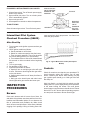
INSPECTION PROCEDURES
32
Burners
32
Controls
32
Inspection Procedures
33
ADDENDA: LOW NOx HEATERS
Models 0181 to 0401
33
Operation
33
Start-Up Procedures
(S8610B Ignition Module)
33
Burner Adjustment
34
Visual Inspection
34
Electrical
34
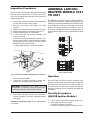
High Gas Pressure Switch
34
Burner Tray Removal
34
Gas Valve Removal
34
Main Burner And Orifice Removal
35
Pilot Removal
35
Combustion Fan Removal
35
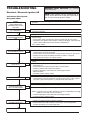
TROUbLESHOOTING
36
Electrical
36
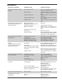
Mechanical
37
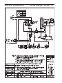
WIRING DIAGRAMS
38
Wiring Diagram—W2/WH2 133
38
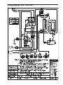
Wiring Diagram—WH1 0181/0261
39
Wiring Diagram—WH1 0331/0401
40
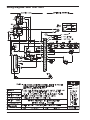
Wiring Diagram—WH1 0514–0724
41
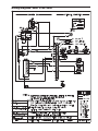
Wiring Diagram—WH1 0824–1826
42
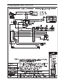
Wiring Diagram—WH1 2100–2500
43
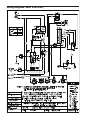
Wiring Diagram—WH1 3001–4001
44
Troubleshooting—Pumps
45
SERVICE AND MAINTENANCE
PROCEDURES
45
Tube Cleaning
45
Burner Tray Removal
46
Gas Valve Removal
46
Gas Valve Adjustment - Robertshaw
(Invensys) 7000 Series 2-Stage Gas Valve
with Solenoid Valve
46
Main Burner and Orifice Removal
47
Pilot Removal and Cleaning
47
High Limit or Tankstat Removal
47
Heat Exchanger Removal
47
Heat Exchanger Re-Assembly
47
Combustion Chamber Removal
48
Control Well Replacement
48
Tube Replacement
48
Cleaning Flue Gas Passageways
48
REPLACEMENT PARTS
48
WARRANTY
50
3
WARNINGS—Pay Attention to These Terms
DANGER:
Indicates the presence of immediate hazards which will cause severe
personal injury, death or substantial property damage if ignored.
WARNING:
Indicates the presence of hazards or unsafe practices which could cause
severe personal injury, death or substantial property damage if ignored.
CAUTION:
Indicates the presence of hazards or unsafe practices which could cause
minor personal injury or product or property damage if ignored.
NOTE:
Indicates special instructions on installation, operation, or maintenance which
are important but not related to personal injury hazards.
DANGER: PROPANE MODELS: Propane gas
must be used with great caution.
• It is heavier than air and will collect first in lower
areas making it hard to detect at nose level.
• Make sure to look and smell for propane leaks
before attempting to light appliance. Use a soapy
solution to check all gas fittings and connections.
Bubbling at a connection indicates a leak that must
be corrected. When smelling to detect an propane
leak, be sure to sniff near the floor too.
• Gas detectors are recommended in propane applications and their installation should be in
accordance with the manufacturer's recommendations and/or local laws, rules, regulations or
customs.
• It is recommended that more than one method be
used to detect leaks in propane applications.
IF PROPANE IS PRESENT OR SUSPECTED:
• DO NOT attempt to find the cause yourself;
• DO NOT try to light any appliance;
• DO NOT touch any electrical switch;
• DO NOT use any phone in your building.
• Leave the building immediately and make sure that
everyone else leaves also.
• Leave the doors open for ventilation and contact
the gas supplier, a qualified service agency or the
fire department.
• Keep the area clear until the service call has been
made, the leak is corrected, and a qualified agency
has determined the area to be safe.
DANGER: Failure to install the draft hood and
properly vent the water heater to the outdoors as
outlined in the Venting section of this manual can
result in unsafe operation of the water heater. To
avoid the risk of fire, explosion, or asphyxiation from
carbon monoxide, never operate this water heater
unless it is properly vented and has an adequate air
supply for proper operation. Be sure to inspect the
vent system for proper installation at initial start-up;
and at least annually thereafter. Refer to the
Maintenance section of this manual for more
information regarding vent system inspections.
DANGER: Water heaters utilizing propane gas are
different from natural gas models. A natural gas
heater will not function safely on propane gas and
vice versa. Conversion from Natural gas to propane
gas (or vice versa) must be done by a qualified
service technician. To avoid possible equipment
damage, personal injury or fire: DO NOT connect
this water heater to a fuel type not in accordance
with unit data plate. Propane for propane units,
Natural gas for natural gas units. These units are not
certified for any other type fuel.
WARNING: Gasoline, as well as other flammable
materials and liquids (adhesives, solvents, etc.), and
the vapors they produce, are extremely dangerous.
DO NOT handle, use or store gasoline or other
flammable or combustible materials anywhere near
or in the vicinity of a water heater. Be sure to read
and follow the warning label pictured below and
other labels on the water heater, as well as the
warnings printed in this manual. Failure to do so can
result in property damage, bodily injury, or death.
WARNING: Both propane and natural gas have an
odorant added to help detection. Some people may
not physically be able to smell or recognize this
odorant. If unsure or unfamiliar about the smell
associated with propane or natural gas, ask the gas
supplier. Other conditions, such as "Odorant Fade",
which causes the odorant to "fade", or diminish in
intensity can also hide or camouflage a gas leak.
WARNING: Propane appliances should not be
installed below-grade (for example, in a basement) if
such installation is prohibited by federal, state and/or
local laws, rules, regulations or customs.
4
WARNING - CALIFORNIA PROPOSITION
65: This product contains chemicals known to the
State of California to cause cancer, birth defects or
other reproductive harm.
! DANGER
Vapors from flammable liquids
will explode and catch fire
causing death or severe
burns.
Do not use or store flammable
products such as gasoline solvents or adhesives in the same
room or area near the water
heater.
Keep flammable products:
1. Far away from heater,
2. In approved containers,
3. Tightly closed and
4. Out of children's reach.
Water temperature over 125°F can
cause instant severe burns or death
from scalds.
Water heater has a main
burner and pilot flame.
The pilot flame:
1. Is on all the time or intermittently (IID).
2. Will ignite flammable vapors.
Children, disabled, and elderly are
at highest risk of being scalded.
See instruction manual before setting temperature at water heater.
Vapors:
1. Cannot be seen,
2. Are heavier than air,
3. Go a long way on the floor,
4. Can be carried from other
rooms to the pilot flame by air
currents.
Feel water before bathing or showering.
Temperature limiting valves are
available, see manual.
Installation:
Do not install water heater where flammable products will be
stored or used unless the main burner and pilot flames are at
least 18" above the floor. This will reduce, but not eliminate, the
risk of vapors being ignited by the main burner or pilot flame.
The following chart details the relationship of water
temperature and time with regard to scald injury and
may be used as a guide in determining the safest
water temperature for your applications.
Read and follow water heater warnings and instructions.
GENERAL SAFETY
To meet commercial hot water needs, this heater is
equipped with a manual reset temperature limit that
does not exceed 200°F. However, water temperatures
over 125°F can cause instant severe burns or death
from scalds. This is the preferred temperature setting
when supplying general purpose hot water.
Safety and energy conservation are factors to be considered when setting the water temperature on the
thermostat. The most energy-efficient operation will
result when the temperature setting is the lowest that
satisfies the needs consistent with the application.
Maximum water temperatures occur just after burner
has shut-off. To determine the water temperature
being delivered, turn on the hot water only, place a
thermometer in the stream, and read the thermometer.
Temperature
Time to Produce Serious Burn
120°F
More than 5 minutes
125°F
1-1/2 to 2 minutes
130°F
About 30 seconds
135°F
About 10 seconds
140°F
Less than 5 seconds
145°F
Less than 3 seconds
150°F
About 1-1/2 seconds
155°F
About 1 second
Table courtesy of Shriners Burn Institute.
Table A: Time to Produce Serious Burn
5
RECEIVING EQUIPMENT
Time/Temperature
Relationships in Scalds
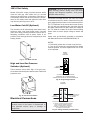
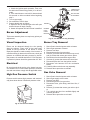
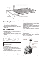
WARNING: Pump motors should NOT be
supported by any type of stand or support from
above due to possible misalignment of pump and
motor which might occur.
The temperature of the water in the storage tank
heater can be regulated by setting the temperature
dial on front of the tankstat. To comply with safety regulations, the tankstat was set at its lowest setting
before shipment from the factory.
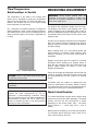
On receipt of the equipment, visually check for external damage to the carton or the shipping crate. If the
carton or shipping crate is damaged, make a note on
the Bill of Lading and report the damage to the Carrier
immediately. Remove the heater from the carton or the
shipping crate.
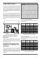
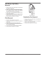
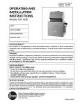
Fig. 1 illustrates a mechanical tankstat. To adjust the
water temperature, insert a small straight screwdriver
into slotted screw in hole in front of tankstat and turn
wheel to desired setting. Thermostat is adjustable up
to 190°F.
Do NOT use the shipping crate base as an installation
base. On occasion, items are shipped loose. Be sure
that you receive the number of packages indicated on
the Bill of Lading.
When ordering parts, you must specify Model and
Serial Number of the heater. When ordering under
warranty conditions, you must also specify date of
installation.
Raypak recommends that this manual be reviewed
thoroughly before installing your Raypak heater. If
there are any questions which this manual does not
answer, please contact the factory or your local
Raypak representative.
Fig. 1: Tankstat Adjustment
Claims for shortages and damages must be filed with
carrier by consignee. Permission to return goods must
be factory-authorized and are subject to a stocking
charge.
DANGER: There is a Hot Water SCALD Potential if
the tankstat is set too high.
Purchased parts are subject to replacement only
under the manufacturer's warranty. Debits for defective replacement parts will not be accepted and will be
replaced in kind only per our standard warranties.
CAUTION: Hotter water increases the risk of
SCALDING!
NOTE: When this heater is supplying general
purpose hot water requirements for use by
individuals, a thermostatically controlled mixing
valve for reducing point of use water temperature is
recommended to reduce the risk of scald injury.
Contact a licensed plumber or the local plumbing
authority for further information.
Model Identification
The model identification number and the heater serial
number are found on the heater data plate. The model
number will have the form WH1-0514A or similar
depending on the heater model. (WH = Hot Water
Supply System, 1 = on/off firing, 0514 = size of
heater).
Rated inputs are suitable for up to 2000 feet elevation.
For elevations above 2000 feet, reduce input 4% for
each 1000 feet above sea level.
6
General Specifications
TYPE WH3 with 2-STAGE
CONTROLS
Models 0181-4001
The Raypak water heaters are design certified and
tested under the latest requirements of the American
National Standard, ANSI Z21.10.3/CSA 4.3. Each
heater has been constructed and pressure tested in
accordance with the requirements of Section IV of the
American Society of Mechanical Engineers Code, and
factory fire tested. Materials are CSA-certified for lowlead content (<.25%).
Hot water supply heater with low-high fire for 2-stage
control. Available with integrally mounted pump, factory mounted and wired for models 0181-1826. To be
used with storage tank systems.
INSTALLATION
All Models (Approved)
Installation Codes
All models are National Board approved. Temperature
and pressure gauge is standard. Intermittent ignition
device is standard on models 0514 and up.
Installation must be in accordance with local codes, or,
in the absence of local codes, with the latest editions
of the National Fuel Gas Code, ANSI Z223.1/NFPA 54,
and the National Electrical Code, ANSI/NFPA 70. In
Canada installations must conform with the current
CAN/CSA B149 and the Canadian Electrical Code
Part 1 CSA C22.2 No.1. Where required by the authority having jurisdiction, the installation must conform to
American Society of Mechanical Engineers Safety
Code for Controls and Safety Devices for
Automatically Fired Heaters, CSD-1.
Model 0133 has 4-pass heat exchanger, 1 tube per
pass.
Models 0181-0401 have 2-pass heat exchangers, 5
tubes first pass, 4 tubes second pass.
Models 0514-1826 have 2-pass heat exchangers, 5
tubes first pass, 4 tubes second pass.
Models 2100-4001 have 2-pass heat exchangers, 9
tubes per pass.
Models 0926-4001 have optional single pass with cast
iron headers only.
Installation base
Hot Water Supply Heaters
The heater should be mounted on a level, non-combustible surface. Heater must not be installed on
carpeting. The heater can be installed on a combustible surface only when the appropriate listed floor
shield base is provided. An optional listed floor shield
base is available for factory installation with the heater
on all indoor models. Do NOT use the shipping base
crate as an installation base.
All Raypak hot water supply heaters are ASME rated
and design certified as hot water heaters, with 125 PSI
pressure relief valves.
TYPE WH1 with ON/OFF CONTROLS
Models 0133-4001
NOTE: The heater should be located in an area
where water leakage will not result in damage to the
area adjacent to the appliance or to the structure.
When such locations cannot be avoided, it is
recommended that a suitable drain pan, adequately
drained, be installed under the appliance. The pan
must not restrict air flow.
To be used with storage tank systems. Available with
integrally mounted pump, factory mounted and wired
for models 0133-1826. Models 0181, 0261, 0331 and
0401 are Low NOx Hot Water Heaters.
TYPE WH2 with MODULATING
CONTROLS
Models 0133-4001
In addition, the heater shall be installed such that the
gas ignition system components are protected from
water (dripping, spraying, rain, etc.) during appliance
operation and service (circulator replacement, control
replacement, etc.).
Hot water supply heater with 110°-170°F gas modulation. Available with integrally mounted pump, factory
mounted and wired for models 0133-1826. To be used
with storage tank systems.
7
Clearances
Heater
Floor Base
Model
Part
Number
Number
001749
0133
058313
0182/0181
0260/0261
058314
0330/0331
058315
0400/0401
058316
0514
056199
0624
056200
0724
056201
0824
056202
0926*
054597
1083*
054598
1178*
054599
1287*
054600
1414*
054601
1571*
058378
1758*
058379
0962
059233
1125
059234
1223
059235
1336
059236
1468
059237
1631
059238
1826
059239
*Models with factory installed floor
shield as standard.
BOLD TYPE indicates Low NOx models.
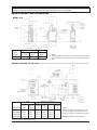
Installation Clearances
(All Dimensions are in Inches)
0133
Location
Floor
Front
Back
Right
Left
*Vent
Indoor Top
Outdoor Top
12
6
12
6
42
Heater Size
0514 to 0926 to
0824
1826
See Note 1
See Note 2
12
12
24
12
6
24
12
18
24
6
6
6
39
36
24
Unobstructed
0181 to
0401
2100 to
4001
24
24
24
6
24
NA
Note 1: Combustible floor shield is required when heater is to be
installed on a combustible surface. (See ordering info.)
Note 2: Servicing Clearances: Provide at least 24" (Models 01331826), 48" (Models 2100-4001) in front of unit for removal &
servicing of the Controls & Burner Tray. Provide at least 18" on side
opposite water connections for deliming of Heat Exchanger Tubes.
*Vent includes factory supplied drafthoods and does not include field
supplied vent systems above the drafthood. On Models 2100-4001
drafthood is built into heater.
Table C: Clearances From Combustible Surfaces
0133
Description
a. 3-1/2 in. thick masonry walls
without ventilated air space.
Table B: Combustible Floorshield Ordering Information
b. 1/2 in. insulation board
over 1 in. glass fiber or
mineral wool batts.
c. 0.024 sheet metal over 1 in.
glass fiber or mineral wool
batts reinforced with wire
on rear face with ventilated
air space.
d. 3-1/2 in. thick masonry wall
with ventilated air space.
e. 0.024 sheet metal with
ventilated air space.
f. 1/2 in. thick insulation
board with ventilated
air space.
g. 0.024 sheet metal with
ventilated air space over
0.024 sheet metal with
ventilated air space.
Fig. 2: Alternate Method for Providing a NonCombustible Base
h. 1 in. glass fiber or mineral
wool batts sandwiched
between two sheets 0.024
sheet metal with ventilated
air space.
Location
Back
Right
Left
Vent
Indoor Top
Outdoor Top
Back
Right
Left
Vent
Indoor Top
Outdoor Top
Back
Right
Left
Vent
Indoor Top
Outdoor Top
Back
Right
Left
Vent
Indoor Top
Outdoor Top
Back
Right
Left
Vent
Indoor Top
Outdoor Top
Back
Right
Left
Vent
Indoor Top
Outdoor Top
Back
Right
Left
Vent
Indoor Top
Outdoor Top
Back
Right
Left
Vent
Indoor Top
Outdoor Top
9
5
9
5
43
0181 to
0401
9
9
9
5
39
6
3
6
3
30
6
6
6
3
30
4
3
4
3
24
4
4
4
3
24
6
6
6
6
42
NA
4
2
4
2
24
6
6
6
6
39
4
3
4
3
24
NA
4
3
4
3
24
4
4
4
3
24
4
3
4
3
24
NA
4
4
4
3
24
4
4
4
2
24
4
4
4
3
24
Heater Size
0514 to 0926 to 2100 to
0824
1826
4001
9
16
16
5
16
16
12
16
16
5
5
5
36
24
24
Unobstructed
NA
6
12
12
3
12
12
9
12
12
3
3
3
24
16
16
Unobstructed
NA
4
8
8
3
8
8
6
8
8
3
3
3
18
12
12
Unobstructed
NA
6
8
8
6
8
8
6
8
8
6
6
6
36
24
24
Unobstructed
NA
4
8
8
2
8
8
6
8
8
2
2
2
18
12
12
Unobstructed
NA
4
8
8
3
8
8
6
8
8
3
3
3
18
12
12
Unobstructed
NA
4
8
8
3
8
8
6
8
8
3
3
3
18
12
12
Unobstructed
NA
4
8
8
3
8
8
6
8
8
3
3
3
18
12
12
Unobstructed
NA
Table D: Clearances to Protected Surfaces
8
NOTE: The heater shall be installed in a space large in comparison to the size of the heater. Large space is
defined as having a volume at least sixteen (16) times the total volume of the heater.
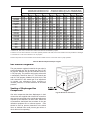
Specifications and Dimensions
MODEL 0133
Indoor
Outdoor
Model
Number
Input MBH
Recovery
GPH*
Recovery
GPH*
WH-0133
136.0
135
132
NOTE:
Ratings are shown for elevations up to 2,000 feet. For elevations
over 2,000 feet, reduce ratings 4% for each 1,000 feet above sea
level.
* Recovery based on manufacturer’s rating.
MODELS 0182-0400 and 0181-0401
Indoor
Dimensions (in inches)
Flue
Diameter
Recovery
GPH*
Width
Model Number
Input
MBH
Height
A
C
J
K
WH-0182/0181
181.0
180
18-1/4
62-5/8
12-1/16
6
WH-0206/0261
264.0
262
22-3/8
62-7/8
11-1/8
7
WH-0330/0331
334.0
332
25-3/4
63-3/4
10-3/4
8
WH-0400/0401
399.0
397
29-1/4
65-3/8
12-1/2
9
* Recovery based on manufacturer’s rating.
9
NOTE:
Ratings are shown for elevations up to 2,000
feet. For elevations over 2,000 feet, reduce
ratings 4% for each 1,000 feet above sea level.
Bold type indicates Low NOx models.
MODELS 0514-0824
Indoor/Outdoor
Model
Number
WH-0514
WH-0624
WH-0724
WH-0824
Input
MBH
511.5
627.0
726.0
825.0
Dimensions (in inches)
Recovery
GPH*
508
623
722
820
Width
Gas
Conn.
A
G
K
L
32-3/4
37-1/2
41-5/8
45-3/4
1
1
1
1
10
12
12
14
25-3/8
29-1/2
34-1/4
38-1/2
Flue
Diameter
NOTE:
Ratings are shown for elevations up to
2,000 feet. For elevations over 2,000 feet,
reduce ratings 4% for each 1,000 feet above
sea level.
* Recovery based on manufacturer’s rating.
MODELS 0 962-1826
Dimensions (in inches)
Overall
Height
Jacket
Height
Gas
Conn.
Water
Conns.
Flue
Diameter
Model
Number
Input
MBH
Recovery
GPH*
Width
A
B
C
G
H
J
K
L
WH-0962
961.7
956
52-3/8
68-3/4
33-1/2
1
2-1/2
18
14
28
WH-1125
1124.7
1118
59-1/4
74-1/2
33-1/2
1
2-1/2
23-5/8
16
32
WH-1223
1222.5
1215
63-5/8
74-1/2
33-1/2
1-1/4
2-1/2
23-5/8
16
32
WH-1336
1336.6
1328
68-5/8
76-1/2
33-1/2
1-1/4
2-1/2
23-5/8
18
36
WH-1468
1467.0
1458
74-7/8
76-1/2
33-1/2
1-1/4
2-1/2
23-5/8
18
36
WH-1631
1630.0
1620
82-1/8
79-1/2
36-1/2
1-1/4
2-1/2
23-5/8
18
36
WH-1826
1825.6
1814
89-3/8
81-1/2
36-1/2
1-1/4
2-1/2
23-5/8
20
40
* Recovery based on manufacturer’s rating.
10
NOTE:
Ratings are shown for elevations
up to 2,000 feet. For elevations
over 2,000 feet, reduce ratings
4% for each 1,000 feet above sea
level.
MODELS 0 926-1758
Dimensions (in inches)
Model
Number
Input
MBH
Recovery
GPH*
Width
Gas
Conn.
Water
Conns.
A
G
H
WH-0926
926.0
920
52-3/8
1
2-1/2
WH-1083
1083.0
1076
59-1/4
1
2-1/2
WH-1178
1178.0
1171
63-5/8
1-1/4
2-1/2
WH-1287
1287.0
1279
68-5/8
1-1/4
2-1/2
WH-1414
1413.0
1404
74-7/8
1-1/4
2-1/2
WH-1571
1570.0
1560
82-1/8
1-1/4
2-1/2
WH-1758
1758.0
1747
89-3/8
1-1/4
2-1/2
NOTE:
Ratings are shown for elevations up to 2,000 feet. For elevations
over 2,000 feet, reduce ratings 4% for each 1,000 feet above sea
level.
* Recovery based on manufacturer’s rating.
MODELS 2100-4000
MODEL,
Dimensions (in inches)
Overall
Height
Gas
Conn.
Water
Conns.
A
B
G
H
K
61
68-1/4
**
3
24
70
68-1/4
**
3
26
81-1/4
68-1/4
2
3
28
92-1/2
68-1/4
2
3
30
103-3/4
68-1/4
2
3
32
Model
Number
Input
MBH
Recovery
GPH*
Width
WH-2100
2100.0
2087
WH-2500
2499.0
2484
WH-3001
3000.0
2982
WH-3500
3500.0
3479
WH-4001
4000.0
3976
Flue
Diameter
* Recovery based on manufacturer’s rating.
** 1-1/2” or 2” contingent on code requirements
11
NOTE:
Ratings are shown for elevations up to 2,000 feet. For
elevations over 2,000 feet, reduce ratings 4% for each
1,000 feet above sea level.
Outdoor Water Heaters
CAUTION: Combustion air must not be
contaminated by corrosive chemical fumes which
can damage the heater. Measures must be taken to
prevent the entry of corrosive chemical fumes to the
combustion and ventilation air supply. Such
chemicals include, but are not limited to, chlorinated
and/or fluorinated hydrocarbons such as found in
refrigerants, aerosol propellants, dry-cleaning fluids,
degreasers, and paint removers. Other harmful
elements may come from bleaches, air fresheners,
or mastics. Vapors from these types of products can
form corrosive acid compounds when burned in a
gas flame. The resulting acidic condensate can
damage or substantially reduce the life of the heater.
It may become necessary to provide outside air
directly to the heater in order to avoid this problem.
These heaters are design certified for outdoor installation. Heaters must not be installed under an overhang
of less than three (3) feet from the top on the heater.
Three (3) sides must be open in the area under the
overhang. Roof water drainage must be diverted away
from the heaters installed under overhangs with the
use of gutters.
The point from where the flue products exit the heater
must be a minimum of four (4) feet below, four (4) feet
horizontally from or one (1) foot above any door, window or gravity inlet to a building. The top surface of the
heater shall be at least three (3) feet above any forced
air inlet, or intake ducts located within ten (10) feet horizontally.
a. All Air From Inside The Building:
Each opening shall have a minimum net free square
inches as noted:
Square
Inches
Model
Model
0133
136
1223
0182/0181
181
1336
0260/0261
264
1468
0330/0331
334
1631
0400/0401
399
1826
0514
512
2100
0624
627
2500
0724
726
3001
0824
825
3500
0962
962
4001
1125
1125
BOLD TYPE indicates Low NOx models.
Square
Inches
1223
1337
1467
1630
1826
2100
2499
3000
3500
4000
Table E: All Air From Inside The Building
Fig. 3: Outdoor Clearances from Openings
High Wind Conditions (Outdoor
Units Only)
b. All Air From Outdoors:
When air is supplied directly from outside of building,
each opening shall have a minimum net free square
inches as noted:
In areas where high winds are frequent, it may be necessary to locate the heater a minimum of 3' from high
vertical walls, or install a wind break so the heater is
not in direct wind current.
Square
Inches
Model
Model
0133
34
1223
0182/0181
46
1336
0260/0261
66
1468
0330/0331
84
1631
0400/0401
100
1826
0514
128
2100
0624
157
2500
0724
182
3001
0824
207
3500
0962
241
4001
1125
282
BOLD TYPE indicates Low NOx models.
Combustion Air (Indoor Units
Only) Air for Combustion and
Ventilation
The heater must have both combustion and ventilation
air. Minimum requirements for net free air supply
openings are 12 inches from ceiling for ventilation and
12 inches from the floor for combustion air as outlined
in ANSI Z223.1, and any local codes that may have
jurisdiction.
Table F: All Air From Outdoors
12
Square
Inches
306
335
367
408
457
525
625
750
875
1000
Models 0181-0401 and 0182-0400
NOTE: If louvers, grills or screens are used on the
openings, obtain the net free area from their supplier or manufacturer. If the design free area of a louver
is not known nor available, it shall be assumed that
wood louvers will have 20-25 percent free area and
metal louvers will have 60-75 percent free area as
specified in the National Fuel Gas Code.
Outdoor Top
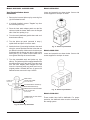
Venting
Outdoor Installations
Model 0133
1. Remove the front (4) screws.
2. Line up outdoor top vent opening over heater vent
opening.
OUTDOOR
FLOOR BASE
3. Lower outdoor top onto unit lining up slots in the
outdoor top with screws holes in jacket top.
4. Reinstall (5) screws to secure jacket top and outdoor top to unit.
8-3/8"
Fig. 5: Outdoor Top Installation
Vent Terminal (Outdoor) Stackless Top
Installation
1. Insert tabs into keyhole (4 places).
2. Snap tabs into keyholes so as not to pull out.
Pagoda Top (Shipped Loose with Heater)
Fig. 6: Outdoor Top Installation
Fig. 4: Outdoor Top Installation
13
Models 0514-0824
Models 0926-1758
1. Lower outdoor "Stackless" top onto unit. Position
top so it is centered on unit from side-to-side and
front-to-rear.
Heaters are shipped with outdoor vent terminal factory installed.
Models 2100-4001
These units are not certified for outdoor installation.
Indoor Installations
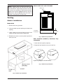
Model 0133
Refer to Fig. 9 on the following page.
1. Shut-off main electrical power switch to heater.
2. Turn heater manual ON/OFF switch, located in
upper control panel, to the "OFF" position.
3. Shut-off gas supply and water supply to the
heater.
4. Mount drafthood on heater and attach with the 8
sheet metal screws provided. Drafthood should be
positioned with the vent sensor located on the
front left side as shown.
Fig. 7: Outdoor Top Installation
2. Tighten the (4) screws (Shown below) until they
come in contact with the unit jacket top, then evenly tighten all (4) screws to secure to unit.
5. Remove plastic plug from left side of heater jacket
and install the plastic grommet provided.
6. Route flue sensor wire harness through the grommet installed in Step 5.
7. Remove door and locate wire from roll out sensor
to High Limit with the male/female connector.
8. Disconnect male/female connector and attach to
the 2 wires from drafthood vent sensor harness.
Fig. 8: Outdoor Top Installation
14
Fig. 9: Indoor Top Installation
15
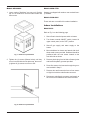
Models 0181-0401 and 0182-0400
Models 0514-0824
Vent Terminal/Indoor Stack
Installation
Locate and assemble as shown below. Secure with
screws supplied in envelope in carton.
1. Remove the louvered jacket top by removing four
(4) #10 flathead screws.
2. If originally installed, remove "Pagoda" top from
the louvered jacket top.
3. Place the inner stack adapter panel over the flue
collector inside the heater. Make sure the flanged
side of the flue opening is up.
4. Turn the stack (drafthood) upside down and set it
down bottom side up.
5. Turn the jacket top panel (removed in step 1)
upside down and place it over the stack.
6. Attach the three (3) mounting brackets to the stack
using the screws provided and the holes that are
pre-drilled in the stack. Make sure the brackets are
positioned with the flange near the top side of the
stack (see Fig. 10). Caution must be taken not to
over tighten and strip the screw threads.
Fig. 11: Indoor Top Installation
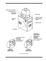
Models 0962-1826
Locate and assemble as shown below. Secure with
screws supplied in envelope in carton.
7. Turn the assembled stack and jacket top, right
side up. The jacket top will be trapped between the
brackets and the top of the stack. Place the stack
over the inner adapter panel flanged hole and
lower the louvered jacket top panel back into its
original position. Reinstall the four (4) green #10
flathead screws removed in step 1 above.
DRAFTHOOD
SCREW HOLE
LOCATION
3-1/4"
JACKET TOP PANEL
(part of the heater)
#10 SHEET METAL SCREW (3)
MOUNTING BRACKET (3)
INNER STACK ADAPTER PANEL
Fig. 12: Indoor Top Installation
FLUE COLLECTOR
(part of heater)
Models 2100-4001
COMBUSTIBLE FLOOR SHIELD
These models have built-in drafthoods. For proper
operation, the drafthood outlet must be connected to
the venting system.
(optional for indoor)
2-1/2"
Fig. 10: Indoor Top Installation
16
Vent Piping
10' OR LESS
VENT CAP
2' MIN
WARNING: Indoor heaters require a drafthood that
must be connected to a vent pipe and properly
vented to the outside. Failure to follow this procedure
can cause fire or fatal carbon monoxide poisoning.
2' MIN
5' MIN
VENT PIPE
Vent piping of the same size as the drafthood outlet is
recommended, however, when the total vent height is
at least ten (10) feet (drafthood relief opening to vent
terminal), the vent pipe size may be reduced as specified in the National Fuel Gas Code, ANSI Z223.1.
DRAFT HOOD
HEATER
Avoid long horizontal runs of vent pipe and too many
elbows. If installation requires horizontal non-vertical
runs, the vent pipe must have a minimum of 1/4 inch
per foot rise and should be supported at not more than
five foot intervals. Plumber's tape, crisscrossed, will
serve to space both horizontal and vertical piping. Gas
vents supported only by the flashing and extending
above the roof more than five feet should be securely
guyed or braced to withstand snow and wind loads.
We recommend use of an insulated vent pipe spacer
through the roofs and walls.
Fig. 13: Vent Piping
Manifolds that connect more than one heater to a common chimney must be sized to handle the combined
load. Consult available guides for proper sizing of the
manifold and the chimney. At no time should the area
be less than the area of the largest outlet.
For protection against rain or blockage by snow, the
vent pipe must terminate with a vent cap which complies with the local codes or, in the absence of such
codes, to the latest edition of the National Fuel Gas
Code, ANSI Z223.1.
The discharge opening must be a minimum of two feet
vertically from the roof surface and at least 2 feet higher than any part of the building or equipment within ten
feet. The vent stack shall be at least 5 feet in vertical
height above the drafthood outlet. The vent cap location shall have a minimum clearance of 4 feet
horizontally from, and in no case above or below,
unless a 4-foot horizontal distance is maintained, from
electric meters, gas meters regulators and relief equipment.
Fig. 14: Common Vent Piping
At the time of removal of an existing heater, the following steps shall be followed with each appliance
remaining connected to the common venting system
placed in operation, while the other appliances remaining connected to the common venting system are not
in operation.
The weight of the vent stack or chimney must not rest
on heater drafthood. Support must be provided in
compliance with applicable codes. The heater top and
drafthood must be readily removable for maintenance
and inspection. Vent pipe should be adequately supported to maintain proper clearances from combustible
construction Type "B" double wall or equivalent vent
pipe is recommended. However single wall metal vent
pipe may be used as specified in the latest edition of
the National Flue Gas Code ANSI Z223.1.
(a) Seal any unused openings in the common venting
system.
(b) Visually inspect the venting system for proper size
and horizontal pitch and make sure there is no
blockage or restriction, leakage, corrosion or other
deficiency which could cause an unsafe condition.
(c) Insofar as is practical, close all building doors and
windows and all doors between the space in which
the appliances remaining connected to the common venting system are located and other spaces
of the building. Turn on clothes dryers and any
17
appliance not connected to the common venting
system. Turn on any exhaust fans, such as range
hoods and bathroom exhausts, so they will operate at maximum speed. Do not operate a summer
exhaust fan. Close fireplace dampers.
WARNING: Do not use thermally actuated vent
dampers on modulating heater. To do so, may result
in asphyxiation. Use only a mechanically actuated
vent damper device that is electrically interlocked
with the modulating heater operation.
(d) Place in operation the appliance being inspected.
Follow the lighting instructions. Adjust thermostat
so appliance will operate continuously.
(e) Test for spillage at the drafthood relief opening
after 5 minutes of main burner operation. Use the
flame of a match or candle, or smoke from a cigarette, cigar or pipe.
(f) After it has been determined that each appliance
remaining connected to the common venting system is venting properly, return doors, windows,
exhaust fans, fireplace dampers and any other
gas burning appliance to their previous conditions
of use.
(g) Any improper operation of the common venting
system should be corrected so that the installation
conforms with the latest edition of the National
Fuel Gas Code, ANSI Z223.1. When re-sizing any
portion of the common venting system, the common venting system should be re-sized to
approach the minimum size as determined using
the appropriate tables in the National Fuel Gas
Code, ANSI Z223.1.
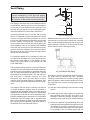
Fig. 15: Vent Damper
Mounting
On vertical vents, the vent damper may be mounted
with the actuator in any position. On horizontal vents,
do not mount the actuator either directly above or
directly below the vent pipe; mount the vent damper
actuator to the side of the vent, as shown in Fig. 16.
For special venting applications that require reduced
vent sizes and through-the-wall venting, the Type D
Induced Draft Assembly can be used. Consult the factory or your local Raypak representative.
Vent Damper Installation
The vent damper is set up for a continuous pilot system. If the vent damper is installed on an Intermittent
Pilot or Direct Spark Ignition equipped system, the
energy savings of the vent damper can be improved
by plugging the hole in the vent damper blade using
the knockout plug, Part No. 105612R, provided in the
parts envelope.
Models 0133 Through 0180
(Where Required)
Location
The vent damper must be located in the vent so that it
serves only the appliance for which it is intended.
DO NOT plug the hole if installing the vent damper on
a continuous pilot system as this will create a hazardous condition.
If improperly installed, a hazardous condition, such as
an explosion or carbon monoxide poisoning, could
result. Make certain that it is mounted in an accessible
location at least 6 in. from any combustible material or
the heat exchanger and that the position indicator is in
a visible location.
The vent damper must be installed after the appliance
drafthood, as close to the drafthood as practicable,
and without modification of the drafthood.
18
Vent Damper
HORIZONTAL INSTALLATION
FLOW >
NO
YES
HEATER
TO BOILER
D808
For safe, efficient operation, the vent damper and all
flue product carrying areas of the appliance must be
checked annually, with particular attention given to
deterioration from corrosion or other sources. Check
vent damper operation as follows:
YES
TO CHIMNEY
NO
VERTICAL
INSTALL VENT
INSTALLATION
DAMPER WITH
TO CHIMNEY
1. When the heater is off, check that the vent damper
position indicator points to the closed position, Fig.
18.
ACTUATOR TO
SIDES OF VENT
ONLY. DO NOT
D808
MOUNT ABOVE OR
BELOW VENT.
INSTALLED IN ANY
HEATER
TO BOILER
Damper
Position
Indicator
Damper
Position
Indicator
ACTUATOR MAY BE
POSITION ON
VERTICAL PIPE.
Fig. 16: Installing Vent Damper
DAMPER OPEN
D808
N.O.
N.C.
End
Fig. 18: Vent Damper position Indicator Showing Open
& Closed Positions
1K2
Switch
C.
DAMPER CLOSED
1K1
Motor
R
2. Turn the thermostat or controller up to call for heat
and check that the vent damper indicator points to
the open position, Fig. 18.
1K3
1R
1
Black
2
Orange
3
4
Yellow
Red
5
Blue
Optional Limit
Limit
Location
3. Turn the thermostat or controller down again and
check that the vent damper position indicator
returns to the closed position.
Thermostat or
Controller
L1
(Hot)
Dual Valve
L2
Combination Gas
Control or
Transformer
1
THE VENT DAMPER MUST BE INSPECTED AT
LEAST ONCE A YEAR BY A TRAINED, EXPERIENCED SERVICE TECHNICIAN. THE NAME OF THE
PERSON WHO ORIGINALLY INSTALLED YOUR
VENT DAMPER IS SHOWN ON THE INSTALLATION
LABEL. DAMPER MUST BE IN THE OPEN POSITION WHEN HEATER MAIN BURNERS ARE
OPERATING.
Ignition System
1
Power supply
provide
disconnect
me
ans an
protection
as requ as required.
ired.
Power
supply
provide
disconnect
means
anoverload
overload
protection
Fig. 17: Vent Damper General Wiring Diagram
INSTALL THE VENT DAMPER TO SERVICE ONLY
THE SINGLE APPLIANCE FOR WHICH IT IS
INTENDED. IF IMPROPERLY INSTALLED, A HAZARDOUS CONDITION, SUCH AS AN EXPLOSION
OR CARBON MONOXIDE POISONING, COULD
RESULT.
19
Plumbing
CAUTION: The heater and its manual shut-off
valve must be disconnected from the gas supply
during any pressure testing of that system at test
pressures in excess of 1/2 PSIG. Dissipate test
pressure in the gas supply line before reconnecting
the heater and its manual shut-off valve to gas
supply line. FAILURE TO FOLLOW THIS
PROCEDURE MAY DAMAGE THE GAS VALVE.
OVER PRESSURED GAS VALVES ARE NOT
COVERED BY WARRANTY. The heater and its gas
connections shall be leak tested before placing the
appliance in operation. Use soapy water for leak test
do NOT use open flame.
General
Heater should be located so that any water leaks will
not cause damage to any adjacent areas or structures.
Gas Supply Connections
Gas piping must have a sediment trap ahead of the
heater gas controls, and a manual shut-off valve located outside the heater jacket. All gas piping should be
tested after installation in accordance with local codes.
NOTE: Do not use teflon tape on gas line pipe
thread. A flexible sealant approved for the fuel being
used is recommended.
Fig. 19: Sediment Trap
20
MAXIMUM EQUIVALENT PIPE LENGTH
0133
*0182/0181
*0260/0261
*0330/0331
*0400/0401
0514
0624
0724
0824
0926/0962
1083/1125
1178/1223
1287/1336
1414/1468
1571/1631
1758/1826
2100
2500
3001
3500
4001
NATURAL GAS 1000 BTU/Cubic Foot
.60 SPECIFIC GRAVITY @ 0.5" W.C. PRESSURE DROP
PROPANE GAS 2500 BTU/Cubic Foot 1.53 SPECIFIC GRAVITY @ 0.6" W.C. PRESSURE DROP
1/2"
1"
1-1/4"
2"
2-1/2"
3"
4"
3/4"
1-1/2"
N
P
N
P
N
P
N
P
N
P
N
P
N
P
N
P
N
P
15
35
60
145 200 500
15
30
65
95
250 400
10
20
40
60
140 250 560
15
25
35
85
150 380 360
15
25
60
100 260 250
10
15
35
65
150 130 360 500
10
25
45
100 95
250 340
20
35
80
75
180 260 600
15
25
60
55
130 185 480 500
15
20
45
45
110 150 360 400
10
15
35
35
80
120 300 300
25
25
60
85
220 200
25
20
55
75
180 170 325 560
20
15
45
65
150 165 300 500
15
15
35
50
120 125 250 400
15
10
30
40
100 100 225 340
10
10
25
30
80
75
175 260
15
20
55
55
135 160 400 600
10
15
35
40
85
120 250 500
10
30
30
45
80
200 400 600
5
20
25
35
65
160 300 400
* Models 0181, 0261, 0331, and 0401 are Low NOx units and are not available in propane.
A minimum of 7" WC and a maximum of 10.5" WC upstream pressure under load, and no load conditions must be provided for natural gas
or a minimum of 11" WC and a maximum of 13" for propane.
Pressure drops from the no load condition to the full load condition must be no more than 30% for proper operation.
Table G: Maximum Equivalent Pipe Lengths
Gas Pressure Regulator
The gas pressure regulator located in the gas valve is
preset nominally at 4" WC for natural gas, and 11" WC
for propane. Between the gas valve and the burners is
a 1/8" pipe plug. The pressure at this point, taken with
a manometer, should be about 3.7" WC natural gas
and 10.5" WC propane. Models 0181, 0261, 0331, and
0401 should be 3.9 WC natural gas. If an adjustment
is needed, turn adjustment screw clockwise to
increase pressure, or counter-clockwise to decrease
pressure.
Venting of Diaphragm Gas
Components
Fig. 20: Bleed Line Connection
Gas train components that have diaphragms in their
construction are supplied with a bleed line connection
that must be connected to the outside atmosphere as
required by the National Fuel Gas Code. Under NO
circumstances shall bleed lines terminate in the gas
utilization equipment flue or exhaust system. Care
should be used to prevent obstruction to the bleed
lines, as blocked lines could prevent gas valves or
other devices from operating.
21
Flow Rates
MAXIMUM AND MINIMUM FLOW RATES
2-PASS HEAT EXCHANGER
MODEL
SIZE
0133*
0182/0181
0260/0261
0330/0331
0400/0401
0514
0624
0724
0824
0926
0962
1083
1125
1178
1223
1287
1336
1414
1468
1571
1631
1758
1826
2100
2500
3001
3500
4001
M AX
MIN
1-PASS HEAT EXCHANGER
T
10
P FT
14.7
GPM
10
T
22
P FT
3.3
45
7
9.2
20
15
1.8
HDR
CONN
1-1/4"
1-1/2"
45
45
45
90
10
12
15
9
9.4
9.6
9.8
9
20
20
20
40
22
28
33
21
1.9
1.9
2.0
1.8
1-1/2"
1-1/2"
1-1/2"
2"
90
90
90
90
12
13
15
17
9.5
10
10.5
11
40
40
40
40
26
30
34
38
1.9
2.0
2.1
2.2
2"
2"
2"
2 1/2"
200
200
200
200
200
200
GPM
22
GPM
MIN
T
HDR
P FT CONN
9.7
90
17
2.1
3"
8
9
9
10
10
11
9.7
10.3
10.3
11
11
11.7
90
90
90
90
90
90
18
20
20
21
22
23
2.1
2.3
2.3
2.4
2.4
2.5
3"
3"
3"
3"
3"
3"
MAX
GPM
200
T
8
P FT
90
18
11
40
39
2.2
90
90
90
90
90
20
20
21
22
23
12
12
12.5
12.5
13.2
44
46
48
50
53
40
40
40
40
40
2.9
3.1
3.6
3.9
4.5
2 1/2"
2 1/2"
2 1/2"
2 1/2"
2 1/2"
2 1/2"
90
90
24
26
13.2
14
55
58
40
40
4.9
5.8
2 1/2"
2 1/2"
200
200
11
12
11.7
12.2
90
90
24
26
2.5
2.7
3"
3"
90
90
27
29
14
14.5
60
64
40
40
6.2
7.3
2 1/2"
2 1/2"
200
200
12
13
12.2
13
90
90
27
29
2.7
2.8
3"
3"
90
90
90
200
200
30
32
33
17
20
14.5
15.4
15.4
14.8
15.8
67
72
75
90
102
40
40
40
38
40
8.1
9.7
10.6
3.2
4.3
2 1/2"
2 1/2"
2 1/2"
3"
3"
200
200
200
400
400
13
14
15
9
10
13
14.7
14.7
18
18.8
90
90
90
180
180
30
32
33
19
23
2.8
3
3
4
4.1
3"
3"
3"
4"
4"
200
200
25
29
16.7
17.5
123
144
40
40
6.5
9.3
3"
3"
400
400
12
14
19.5
20.5
180
180
27
32
4.3
4.5
4"
4"
200
33
18.7
164
40
12.8
3"
400
16
21.5
180
36
4.7
4"
GPM Flow rates limited by maximum acceptable velocity through heat exchanger tubes. May be increased by 10% for closed heating systems.
* 4 Pass Heat Exchanger
BOLD TYPE indicates Low NOx models.
Table H: Maximum and Minimum Flow Rates
22
WATER HARDNESS
MEDIUM
SOFT
MODELS
5-15 Grains Per Gallon
0-4 Grains Per Gallon
Indoor
0133
0182/0181
0260/0261
0330/0331
0400/0401
0514
0624
0724
0824
0962
1125
1223
1336
1468
1631
1826
2100
2500
3001
3500
4001
Outdoor
0133
0182
0260
0330
0400
0514
0624
0724
0824
0926
1083
1178
1287
1414
1571
1758
N/A
N/A
N/A
N/A
N/A
T
22
15
21
27
30
20
25
29
30
30
30
30
30
30
30
33
30
30
30
30
33
GPM
10
20
20
20
22
42
41
41
45
53
61
67
73
80
90
90
115
137
164
191
200
P
3.4
1.8
1.9
1.9
2.3
2.0
2.0
2.1
2.6
3.8
5.5
7.0
8.7
11.0
14.8
15.4
5.0
7.5
11.2
16.2
18.7
MPS
1-1/4
1-1/2
1-1/2
1-1/2
1-1/2
2
2
2
2
2-1/2
2-1/2
2-1/2
2-1/2
2-1/2
2-1/2
2-1/2
3
3
3
3
3
HARD
SHL
5.1
4.6
4.6
4.7
5.6
4.8
4.7
4.9
5.9
5.3
7.5
9.3
11.5
14.4
19.0
19.6
7.9
11.4
17.0
23.7
26.8
T
17
12
17
21
25
16
19
20
20
20
20
22
24
27
30
33
20
20
25
29
33
GPM
13
26
26
26
26
52
54
60
68
79
90
90
90
90
90
90
172
200
200
200
200
P
5.5
3.1
3.1
3.2
3.3
3.0
3.4
4.4
6.0
8.5
12.0
12.5
13.3
14.0
14.8
15.4
11.0
15.8
16.7
17.5
18.7
MPS
1-1/4
1-1/2
1-1/2
1-1/2
1-1/2
2
2
2
2
2-1/2
2-1/2
2-1/2
2-1/2
2-1/2
2-1/2
2-1/2
3
3
3
3
3
16-25 Grains Per Gallon*
SHL
8.2
7.5
7.6
7.7
7.8
7.1
7.9
9.8
12.8
11.5
16.2
16.7
17.5
18.2
19.0
19.6
17.2
23.9
24.8
25.6
26.8
T
GPM
10
7
10
12
15
9
11
13
15
18
20
22
24
27
30
33
17
20
25
29
33
22
45
45
45
45
90
90
90
90
90
90
90
90
90
90
90
200
200
200
200
200
P
14.7
9.2
9.4
9.6
9.8
9.0
9.5
10.0
10.5
11.0
12.0
12.5
13.3
14.0
14.8
15.4
14.8
15.8
16.7
17.5
18.7
MPS
SHL
1-1/4
1-1/2
1-1/2
1-1/2
1-1/2
2
2
2
2
2-1/2
2-1/2
2-1/2
2-1/2
2-1/2
2-1/2
2-1/2
3
3
3
3
3
22.0
20.8
21.0
21.2
21.3
19.1
20.9
21.4
21.9
15.2
16.2
16.7
17.5
18.2
19.0
19.6
22.9
23.9
24.8
25.6
26.8
BOLD TYPE indicates Low NOx models.
ΔT = Temperature Rise, Degree F@GPM FLOW
GPM = Gallons per Minute Flow
ΔP = Pressure Drop, Foot thru Heat Exchanger
MPS = Minimum Pipe Size, NPT
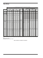
SHL = System Head Loss
* Must utilize optional cupro-nickel tubes. If over 25 grains per gallon, a water softener/treatment system must be utilized.
Table I: General Specifications Uni-Temp 80 Hot Water Supply Systems
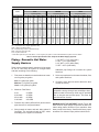
Piping—Domestic Hot Water
Supply Heaters
1-1/2" NPT = 70 Ft (0181-0401)
2" NPT = 75 Ft (0514-0824)
2-1/2" NPT = 80 Ft (0926-1826)
3" NPT = 85 Ft (2100-4001)
Table I above provides data for selecting in-line pumps
for use in a Uni-Temp 80 system for a single heater
and tank according to the following:
Additional pipe fittings will increase the system
head loss.
1. Flow rates are based on water hardness as measured in grains per gallon.
5. Select a pump based on the water hardness, flow,
and system head loss.
Soft: 0-4 grains per gallon.
Medium: 5-15 grains per gallon.
Hard: 16-25 grains per gallon.
6. If heater is more than two stories above the tank,
consult the factory.
NOTE: GPM flow rates are limited by maximum
acceptable velocity through heat exchanger tubes.
Heater models 0514 through 1826 may be provided
with an integral rear-mounted pump. This must be
specified at time of order.
2. Maximum Flow Rates:
0133
0181-0401
0514-1826
2100-4001
22 GPM
45 GPM
90 GPM
200 GPM
3. Pressure drop values (ΔP and SHL) and minimum
pipe sizes are for two-pass heaters.
MINIMUM INPUT ADJUSTMENT: Model Types WH
have minimum input ratings as specified on their individual rating plates. Minimum input controllers have
been pre-set at the factory. Consult with factory representatives if a minimum input problem should occur.
4. Sizing based on heater and tank being placed 5
feet apart. The equivalent length of pipe, valves
and fittings in the system is as follows:
23
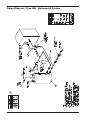
Piping Diagram—Type WH - Unitemp 80 System
24
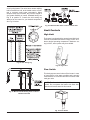
Controls—General
Relief Valve
A new combination temperature and pressure (T&P)
relief valve, complying with the Standard for Relief
Valves and Automatic Gas Shut-Off Devices for Hot
Water Supply Systems, ANSI Z21.22, must be
installed in the opening provided on top of the storage
tank at the time of installation. No valve is to be placed
between the relief valve and the storage tank.
(A)
The pressure rating of the relief valve must not exceed
the 160 maximum working pressure indicated on the
water heater rating plate. The BTUH rating of the relief
valve must not be less than the BTUH input of the
heater.
(B)
Connect the outlet of the relief valve to a suitable open
drain. The discharge line must pitch downward from
the valve to allow complete draining (by gravity) of the
relief valve and discharge line. The discharge line
should be no smaller than the outlet of the valve. The
end of the discharge line should not be threaded or
concealed, and should be protected from freezing. No
valve of any type, restriction or reducer coupling,
should be installed in the discharge line. Local codes
shall govern installation of the relief valve.
6
1
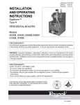
2
Fig. 21: Economaster Time Delay Relays (TDR)
Electronic Ignition
The intermittent ignition device conserves energy by
automatically extinguishing the pilot when desired
temperature is reached. When additional heat is needed, the pilot re-ignites electrically, eliminating the fuel
costs of maintaining a constant pilot. To ensure safe
operation, the gas valve cannot open until the pilot
relights and is confirmed.
Pump Time Delay
There are two versions of the Pump Time Delay. The
first is an electronic device that allows the operator to
set a variable time (3 to 10 minutes) for the pump to
run after the heater shuts off. See Fig. 21 (A). The time
is factory-set at 7 minutes and it can be re-adjusted in
the field.
The second version is a fully enclosed solid state Time
Delay Relay (TDR) with a white jumper that selects
one of two time delays. See Fig. 21 (B). If the jumper
is on pins 6 and 7 (default) the delay time is 5 minutes.
If the jumper is not on pins 6 and 7, the time delay is
10 minutes.
Table J: Electronic Ignition
In a conventional system, when the tankstat is satisfied, the main gas valve closes, but the pump
continues operating. With either time delay relay the
heater pump is programmed to continue running for an
optimum period of time in order to absorb the residual
heat from the combustion chamber and use it in the
system. The pump then shuts off until the next call for
heat is received from the tankstat.
Operating Controls
On models 0514-1826, models with mechanical modulating controls have one or more Robertshaw Unitrol
7000 Series hydraulic snap on thermostatic combination gas valves. These valves have the pressure
regulator and 24-volt operator built-in. The hydraulic
actuator will throttle the heater input to adjust the firing
rate and meet the required load. This, in effect, prevents costly fuel consumption, as compared to an
NOTE: Pump will come on when power is first
applied to heater.
25
on-off cycling heater. The valve has a remote capillary
bulb immersed in a well, at the header outlet, to maintain a constant outlet water temperature. When
multiple valves are furnished, they can be staged to
give greater flexibility of control. Standard factory setting is at position 5. Consult the dial setting tag
attached to the control for your desired temperature.
See Fig. 22 below.
Fig. 24: Motorized Gas Valve Location—Model 3001
Limit Controls
High Limit
The heater is equipped with a manual reset High Limit.
Push the reset button and set the limit(s) to 30°F–40°F
above desired operating temperature. Maximum setting is 200°F; other options may be available.
Fig. 22: Dial Setting Tag
Fig. 25: High Limit
Flow Switch
This dual-purpose control shuts off the heater in case
of pump failure or low water condition and is strongly
recommended. It is mounted and wired in series to the
main gas valve.
NOTE: The flow switch is a safety device and not a
control. Do not operate the heater with flows less
than the minimums stated in this manual.
Fig. 23: Mechanical Modulating Valve Location—
Models 0724-1336
Fig. 26: Flow Switch
26
100% Pilot Safety
CAUTION: Label all wires prior to disconnection
when servicing controls. Wiring errors can cause
improper and dangerous operation. Verify proper
operation after servicing.
Models 0514-4001 employ electronic devices which
close the main gas valve within 8/10 of a second
whenever the pilot flame is interrupted. Pilot flame is
automatically lit when the device is powered. Unit performs its own safety check and opens the main valve
only after the pilot is proven to be lit.
The heater is normally wired for 120 Volts. The voltage
is indicated on the tie-in leads. Consult the wiring diagram shipped with the heater in the instruction packet.
The "TH" leads are for the remote tank control connection. 24 Volts are supplied to this connection through
the heater transformer. DO NOT attach line voltage to
the "TH" leads on models 0514-1826. Before starting
heater check to ensure proper voltage to heater and
pump.
Low Water Cut-Off (Optional)
The low water cut-off automatically shuts down burner
whenever water level drops below probe. 5-second
(max) time delay prevents premature lockout due to
temporary conditions such as power failure or air
pockets. Flush float type devices at beginning of each
heating season.
Heater must be electrically grounded in accordance
with National Electrical Code ANSI/NFPA No 70.
NOTES:
1. Field install ground wire to inside of junction box.
2. If any of the original wire supplied with the heater
must be replaced, it must be replaced with 105°C wire
or its equivalent.
SINGLE
STAGE
TANKSTAT
Fig. 27: Low Water Cut-Off
High and Low Gas Pressure
Switches (Optional)
STAGE 1
CONNECTION
These switches sense either high or low gas pressures and automatically shut down burners if abnormal
pressures exist.
ATTACH STAGE 1 CONNECTIONS
ON HEATER TO THE SINGLE STAGE
TANKSTAT AS SHOWN IN THE DIAGRAM ABOVE.
Fig. 29: Single-Stage Tankstat
2-STAGE
TANKSTAT
Fig. 28: Gas Pressure Switch
STAGE 1
CONNECTION
Electrical Connections
STAGE 2 CONNECTION OR
STAGE 1 CONNECTION
OF HEATER 2
ATTACH STAGE 1 CONNECTIONS ON HEATER
TO STAGE 1 CONNECTION ON TANKSTAT.
ATTACH STAGE 2 CONNECTIONS OR
STAGE 1 CONNECTION OF HEATER 2
TO STAGE 2 CONNECTION ON TANKSTAT
AS SHOWN IN THE DIAGRAM.
DANGER - SHOCK HAZARD: Make sure
electrical power to the heater is disconnected to
avoid potential serious injury or damage to
components.
Fig. 30: 2-Stage Tankstat (2 On/Off Units)
27
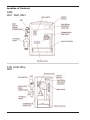
Location of Controls
0400
WH1, WH2, WH3
0181 (LOW NOx)
WH1
28
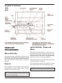
Location of Controls
0824
29
Location of Controls
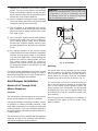
START-UP
PROCEDURES
Initial Start-Up - Pump and
Motor
Many pumps are now direct-drive. They have no coupler or bearing assembly. These pumps do not require
lubrication. Others require SAE-30 non-detergent oil to
lubricate both the motor and the bearing assembly.
Check pump motor for type before adding oil.
before Start-Up
Safe lighting and other performance criteria were met
with the gas manifold and control assembly provided
on the heater when the heater underwent tests specified in the latest edition of the ANSI Z21.10.3/CSA 4.3
Standard.
Clean dust and lint from pump and motor. Check pump
coupler and tighten if necessary.
General
Flush system before putting into operation to ensure
that foreign material does not damage pump seals.
Before lighting up a new installation, water should be
flowing through the heater. Water pressure regulator
should be set to minimum 25 PSI.
CAUTION: Pump must be off to check oil in bearing
assembly. Do not run pump without water in system.
CAUTION: Propane gas is heavier than air and
sinks to the ground. Exercise extreme care in lighting heater in confined areas.
30
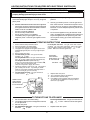
LIGHTING INSTRUCTIONS FOR HEATERS WITH ELECTRONIC IGNITION (IID)
FOR MODELS WITH MANUAL GAS VALVES
FOR YOUR SAFETY READ BEFORE OPERATING
WARNING:If you do not follow these instructions exactly, a fire or explosion may result causing
property damage, personal injury or loss of life.
A. This appliance is equipped with an ignition device
which automatically lights the pilot. Do not try to light the
pilot by hand.
B.
*
*
*
*
BEFORE OPERATING smell all around the appliance
area for gas. Be sure to smell next to the floor because
some gas is heavier than air and will settle on the floor.
WHAT TO DO IF YOU SMELL GAS
Do not try to light any appliance.
Do not touch any electric switch.
Do not use any phone in your building.
Immediately call your gas supplier from your
neighbor’s phone. Follow the gas supplier’s instructions.
*
If you cannot reach your gas supplier, call the fire department.
C.
Use only your hand to push in or turn the gas control
knob. Never use tools. If the knob will not push in or turn
by hand, do not try to repair it. Call a qualified service
technician. Force or attempted repair may result in a fire
or explosion.
D. Do not use this appliance if any part has been under
water. Immediately call a qualified service technician to
inspect the appliance and to replace any part of the
control system and any gas control which has been
under water.
OPERATING INSTRUCTIONS
1.
2.
3.
4.
5.
6.
7.
8.
For Honeywell Gas Valve: Turn gas control knob counterclockwise
from “OFF” until it stops. Push in gas control
knob and continue rotating counter-clockwise
to “ON”
position. Make sure knob rests against stop.
STOP! Read the safety information above.
Set the thermostat on the lowest setting.
Turn off all electric power to the appliance.
This appliance is equipped with an ignition device which
automatically lights the pilot. Do not try to light the pilot
by hand.
Remove heater door panel.
For Robertshaw gas valve: Turn gas control knob
clockwise
to “OFF”.
For Honeywell Gas Valve: Turn gas control knob clockwise
to “OFF". Make sure knob rests against stop.
For Honeywell Gas Valve: (Model 400 only)
Push in gas control knob slightly and turn clockwise
to “OFF”. Knob cannot be turned “OFF”
unless knob is pushed in slightly. Do not force.
Wait five (5) minutes to clear out any gas. Then smell for
gas, including near the floor. If you smell gas, STOP!
Follow “B” in the safety information previously stated. If
you do not smell gas, go to the next step.
For Robertshaw Gas Valve: Turn gas control knob
counter-clockwise
to “ON”.
HONEYWELL
GAS CONTROL
KNOB SHOWN
IN "ON" POSITION
GAS INLET
9.
10.
11.
12.
ROBERT SHAW
GAS CONTROL
KNOB SHOWN
IN "ON" POSITION
Replace heater door panel.
Turn on all electric power to the appliance.
Set thermostat to desired setting.
If the appliance will not operate, follow the instructions
“To Turn Off Gas To Appliance” and call your service
technician or gas supplier.
GAS INLET
TO TURN OFF GAS TO APPLIANCE
1.
2.
3.
4.
Set the thermostat to the lowest setting.
Turn off all the electric power to the appliance if service
is to be performed.
Remove door panel.
For Robertshaw Gas Valve: Turn gas control knob
clockwise
to “OFF”.
31
For Honeywell Gas Valve: Turn gas control knob clockwise
to “OFF”. Make sure knob rests against
stop.
5.
Replace heater door panel.
FOR MODELS WITH AUTOMATIC GAS VALVES
PILOT SHUT-OFF
VALVE CONTROL
SHOWN IN "ON"
POSITION
1. Close all gas valves. Turn off electric power supply.
Wait five (5) minutes.
2. Open manual pilot valve. Turn on electric power.
Pilot is automatically lighted.
3. Open main gas valve.
4. Set temperature controls to desired temperature.
TO SHUT DOWN
GAS INLET
Close all manual gas valves. Turn off electric power.
Intermittent Pilot System
Checkout Procedure (S8600)
TO PILOT
MAIN GAS
SHUT-OFF
VALVE
SHOWN IN
THE "ON"
POSITION
cates excessively high gas pressure. Low flame indicates low gas pressure.
After Start-Up
1. Turn on power to the ignition systems and turn gas
supply off.
2. Check ignition module as follows:
a. Set the tankstat to call for heat.
b. Watch for continuous spark at the pilot burner.
c. Time the spark operation. Time must be within
the lockout timing period (15 or 90 seconds).
d. Turn tankstat down to end call for heat and wait
60 seconds on lockout models before beginning
step 3.
3. Turn on gas supply.
4. Set tankstat to call for heat.
5. Systems should start as follows:
a. Spark will turn on and pilot gas valve will open
at once. Pilot burner should ignite after gas reaches the pilot burner.
b. Spark ignition should cut-off when pilot flame is
established.
c. Main gas valve should open and main burner
should ignite after gas reaches the burner port.
Fig. 31: Typical Main Burner Flame (Atmospheric
Models)
Controls
Check all controls to see that they are operational. To
check electronic safety (IID models), turn off main
burner. Observe pilot burner when shutting off pilot
gas. Ignition spark should go on. Main gas valve will
also drop out.
High Limit Switch - to check high limit switch, turn dial
setting down to a point slightly below the temperature
of the water leaving the heater. The reset button
should snap out and the burner should shut-off. Reset
dial to 30°F to 40°F above desired operating temperature and push reset button. Burner should light.
INSPECTION
PROCEDURES
burners
Clean main burners and air louvers free of dust, lint
and debris. Keep heater area clear and free from combustibles and flammable liquids. Do not obstruct the
flow of combustion and ventilation air. Make visual
check of burner and pilot flame. Yellow flame indicates
clogging of air openings. Lifting or blowing flame indi-
32
ADDENDA: LOW NOx
HEATERS MODELS 0181
TO 0401
Inspection Procedures
Inspect on the first and third month after initial startup
and then on an annual basis. If problems are found,
refer to the Troubleshooting sections of this manual for
additional directions.
The Raytherm Low NOx Heater is offered with WH1On-Off firing (standard) or 2-stage firing (optional). The
heaters are certified and tested under the latest edition
of the ANSI Z21.10.3/CSA 4.3 standard for hot water
heaters. The heater should be installed to meet all
local codes, the National Fuel Gas Code ANSI Z223.1,
and the National Electrical Code, ANSI/NFPA 70-latest
edition.
1. Remove top of heater and inspect heat exchanger
for soot and examine venting system.
2. Remove rear header and inspect for scale
deposits.
*3. Inspect pilot and main burner flame and firing rate.
*4. Inspect and operate all controls and gas valve.
*5. Visually inspect system for water leaks.
*6. a. Oil pump motor and bearing assembly, if oil
cups are provided.
b. Disconnect pump from header and check condition of pump impeller. Check condition of bearing
by attempting to move impeller from side to side.
Replace any parts showing wear.
c. Check pump coupler for wear and vibration.
DETAIL A
SEE DETAIL VIEW A
Fig. 33: Burner Detail
Fig. 32: Pilot Burner Flame—IID (Atmospheric Models)
Operation
7. Check flow switch paddle.
8. Clean room air intake openings to ensure adequate flow of combustion and ventilation air.
On call for heat, the ignition system, consisting of an
electronic spark module, gas pilot system is energized.
Providing pilot is proven, blower will start running, the
main gas valve will open and the heater will operate.
When the operating control is satisfied, the heater will
shut down.
CAUTION: Combustion air must not be
contaminated by corrosive chemical fumes which
can damage the heater and void the warranty.
Start-Up Procedures
(S8610b Ignition Module)
9. Keep heater area clear and free from combustible
materials, gasoline, and other flammable vapors
and liquids.
1. Turn on power to the heater with gas supply off.
2. Check ignition module as follows:
a. Set the tankstat to call for heat.
b. Watch for continuous spark at the pilot burner.
*Should be checked monthly. (Takes approximately
15 minutes).
33
c. Check the ignition spark operation. Time must
be within the lockout timing period (15 or 90 seconds).
d. Turn control down to end call for heat and wait
60 seconds on lockout models before beginning
step 3.
3. Turn on gas supply.
4. Set controller to call for heat.
5. System should start as follows:
a. Spark will turn on and pilot gas valve will open
and the blower will begin running.
b. Heater will operate until call for heat is satisfied.
COMBUSTION
AIR BLOWER
AIR SHUTTER
ADJUSTMENT
GAS
VALVE
BURNER
BURNER
HOLDDOWN
BRACKET
burner Adjustment
This burner assembly does not require any primary air
adjustments.
Fig. 35: Low NOx Burner Tray Assembly
Visual Inspection
burner Tray Removal
Flame can be observed through the slot opening
above the plenum. Flame color is blue and evenly
spread on the top surface of the burner. A visual
inspection should be made monthly of the burners. In
case flame lifting is observed on the burner, check gas
pressure on manifold and static pressure in plenum.
Gas pressure in manifold should be 3.9" WC and static pressure in plenum should be greater than 0.5" WC.
1.
2.
3.
4.
5.
6.
7.
8.
9.
Electrical
10.
11.
Be sure that electrical service to the heater has proper overload fuse or circuit breaker protection, and wire
size and connections comply with all applicable codes.
Shut-off main electrical power switch to heater.
Shut-off gas upstream of heater.
Remove front door.
Disconnect gas line from gas valve.
Remove (2) screws that mount burner tray to unit,
and (4) screws that secure gas valve to jacket.
Disconnect wires that terminate at gas valve.
Unscrew (4) screws that secure the control box.
Disconnect pilot wire from the ignition module.
Disconnect wire harness from the combustion
blower.
Carefully slide out the burner tray assembly.
Reverse above procedure to reinstall.
Gas Valve Removal
High Gas Pressure Switch
1.
2.
3.
4.
5.
Shut-off main electrical power switch to heater.
Shut-off gas supply to the heater.
Remove front door.
Disconnect gas line from gas valve.
Disconnect wires, pilot tubing and bleed line, if
required.
6. Remove (2) screws that secure gas valve to jacket.
7. Turn vertical gas pipe from manifold slightly and
unscrew gas valve.
8. Reverse above procedure to re-install.
Pressure switch senses high pressure and automatically shuts down burner if abnormal pressure exists.
Fig. 34: Gas Pressure Switch
34
Main burner And Orifice
Removal
1. Remove burner tray. (See Burner Tray Removal
procedure on page 34.)
2. Remove (8) screws from the hold-down brackets.
3. Remove (8) screws from the left and right sides of
the manifold assembly. Detach the manifold
assembly from the burner tray assembly.
4. Use a long ½” socket wrench to remove orifices
from the gas manifold.
5. Remove burners by raising the bracket on the
back end of the burners up and out of their slots.
6. Reverse above procedure to re-install.
Fig. 36: IID Pilot
Combustion Fan Removal
Pilot Removal
1. Remove burner tray. (See Burner Tray Removal
procedure on page 34.)
2. Remove (4) screws that mount the combustion
blower to the manifold assembly.
3. Reverse above procedure to re-install.
1. Disconnect pilot tubing from gas valve.
2. Remove (4) screws from control box. Open the
control box.
3. Remove the pilot wire from the ignition wire.
4. Remove (2) screws that mount the pilot bracket to
the air manifold assembly.
5. Pull the pilot bracket downwards and outwards.
6. Reverse above procedure to re-install.
35
TROUbLESHOOTING
WARNING—HIGH VOLTAGE: For qualified
technicians ONLY.
Electrical—Electronic Ignition IID
NOTE: Some heaters may be equipped with an
ignition module that shuts off pilot gas if pilot fails to
light. To reset, interrupt power to heater.
Intermittent Pilot System
Honeywell S8600
START
TURN GAS SUPPLY OFF.
TURN THERMOSTAT
(CONTROLLER) TO CALL
FOR HEAT
POWER TO MODULE
(24 V NOMINAL)?
YES
NOTE: Before troubleshooting, familiarize yourself with the start-up and checkout
procedure.
NO
Check line voltage power, low voltage transformer, limit controller, thermostat
(controller) and wiring.
Pull ignition lead and check spark at module.
SPARK ACROSS
IGNITER/SENSOR GAP?
YES
NO
TURN GAS SUPPLY ON
PILOT BURNER LIGHTS?
YES
NO
SPARK STOPS WHEN
PILOT IS LIT?
YES
NO
MAIN BURNER LIGHTS?
YES
NO
SYSTEM RUNS UNTIL
CALL FOR HEAT ENDS?
YES
NO
If spark is okay:
• Check ignition cable, ground wiring, ceramic insulator and gap, and correct.
• Check boot of the ignition cable for signs of melting or buckling. Take protective
action to shield cable and boot from excessive temperatures.
If not, replace module.
• Check that all manual gas valves are open, supply tubing and pressures are good,
and pilot burner orifice is not blocked.
• Check electrical connections between module and pilot operator on gas control.
• Check for 24 Vac across PV-MV/PV terminals on module. If voltage is
okay, replace gas control; if not, replace module.
NOTE: If S8600H goes into lockout, reset system. Lockout is used on propane
models.
• Check continuity of ignition cable and ground wire.
• Clean flame rod.
• Check electrical connections between flame rod and module.
• Check for cracked ceramic flame rod insulator.
• Check that pilot flame covers flame rod and is steady and blue.
• Adjust pilot flame.
• If problem persists, replace module.
• Check for 24 Vac across MV-MV/PV terminals. If no voltage, replace module.
• Check electrical connections between module and gas control. If okay, replace
gas valve or gas control operator, i.e. pilot gas valve, flow switch etc.
NOTE: IF S8600H goes into lockout, reset system.
• Check continuity of ignition cable and ground wire.
NOTE: If ground is poor or erratic, shutdowns may occur occasionally even though
operation is normal at the time of checkout.
• Check that pilot flame covers flame rod and is steady and blue.
• If checks are okay, replace module.
CALL FOR HEAT ENDS
SYSTEM SHUTS OFF?
YES
NO
• Check for proper thermostat (controller) operation.
• Remove MILLIVOLT lead at module; if valve closes, recheck temperature
controller and wiring; if not, replace gas valve.
TROUBLESHOOTING ENDS
36
Mechanical
CORRECTIVE ACTION
MECHANICAL PROBLEM
POSSIBLE CAUSE
When heater is turned on nothing
happens.
No power to the heater…………………. Check the circuit breaker, outdoor controller, etc., upstream of heater.
Bad transformer…………………………. If power to Leads L1 and L2 of transformer, but no power on 24V side, replace.
Inoperative thermostat………………….. Jumper thermostat, replace with new if
heater fires.
Inoperative toggle switch……………….. If power to toggle switch, but not through
switch, replace.
Inoperative relay…………………………. If power to relay, but not operating, replace.
Thermostat in "ON" position causes
relay and pump to operate, but
heater does not fire.
Main gas valve closed………………...... Open valve.
Plugged bleed line on gas valve or
gas pressure regulator………………….. Loosen bleed line and clean.
Broken pump coupler…………………… Replace coupler. Inspect bearing assembly, and if frozen, lubricate or replace.
Shutdown by low water cut-off,
caused by air…………………………….. Bleed air from system.
Gas valve defective…………………….. Check for power to gas valve. If valve has
power but will not open, check vent tube
for blockage. If clear, replace valve.
Continuous shut down of manual
reset High Limit.
Temperature setting too low…………….
Low water flow……………………………
Interrupted pump operation……………..
Modulating control set too high………..
Mechanical modulating control…………
Sooting
CAUTION-Soot may be combustible. Wet down and exercise
caution when cleaning.
Refer to installation instructions regarding combustion air requirements.
Condensation……………………………. Set bypass valve to prevent heater inlet
temperature from dropping below 105° F.
Toxic fumes which cause a chemical
reaction with copper tubes or destroy
combustion………………………………. Remove all sources of fumes, such as
freon or chloride, or isolate the heater.
Improper venting………………………… Follow recommended vent installation
instructions.
Continuous shut down of low water
cut-off or flow switch.
Insufficient system flow…………………. Check pumps and piping.
Low water due to leaking……………….. Inspect for leaking and repair.
Air in system……………………………... Inspect for leakage and repair. Install an
automatic air vent.
Line strainer dirty………………………… Clean.
Lime in Heat Exchanger………………… Ream tubes.
Low flame.
Low gas supply………………………….. Debris in gas line (pipe dope, rocks, etc.).
Gas line too small.
Improper size gas meter.
Gas regulator adjustment.
Insects or debris clogging………………. Clean burners.
Burner intake ports low gas pressure…. Adjust gas pressure.
Venting or combustion air………………. Refer to installation instructions regarding combustion air requirement.
Outer jacket very hot (blistered paint)
Broken refractory…..……………………. Replace refractory panels.
Combustion fan not running.
(If applicable)
Fan relay................................................ Replace fan relay.
Fan......................................................... Loose wire connection.
Failed fan motor.
Reset High Limit to higher temperature.
Check system water pumps.
Check pump oil if necessary.
Reset modulator to a lower setting.
Check and replace if necessary.
Air starvation……………………………..
37
WIRING DIAGRAMS
Wiring Diagram—W2/WH2 133
38
Wiring Diagram—WH1 0181/0261
39
Wiring Diagram—WH1 0331/0401
40
Wiring Diagram—WH1 0514–0724
41
Wiring Diagram—WH1 0824–1826
42
Wiring Diagram—WH1 2100–2500
43
Wiring Diagram—WH1 3001–4001
44
Troubleshooting—Pumps
Pump Loses Prime
Failure To Pump
1.
2.
3.
4.
1.
2.
3.
4.
Pump not properly primed.
Wrong direction of rotation.
Speed too low.
Total head too high.
Air leaks in suction line.
Excess air in water.
Water seal in stuffing box not functioning.
Excessive suction lift and pump operating too near
shut-off point.
Overloaded Driving Unit
Reduced Capacity and/or Head
1. Head much lower than that for which pump is
designed.
2. Speed too high or higher than that contemplated.
1.
2.
3.
4.
5.
6.
Air pockets or leaks in suction line.
Clogged impeller.
Foot valve strainer too small or clogged.
Excessive suction lift (over 15 feet).
Insufficient positive suction head (for hot water).
Total head more than that for which pump is
intended.
7. Excessively worn impeller and wearing rings.
Mechanical Troubles and Noise
1.
2.
3.
4.
Rapid Wear of Coupling
Misalignment.
Excessive suction lift or vapor binding (hot water).
Bent shaft and/or damaged bearings.
Suction and discharge piping not properly supported and anchored.
1. Misalignment or a bent shaft.
2. Sagging motor mounts (over-oiling).
SERVICE AND
MAINTENANCE
PROCEDURES
The heater may be cleaned from the side opposite the
water connections as shown, without breaking pipe
connections. It is preferable, however, to remove both
headers for better visibility through the tubes and to be
sure the residue does not get into the system. Note
that you do not remove the top pan or the heat
exchanger generally. After reaming with the auger,
mount the wire brush and clean out the debris remaining in the tubes. Another method is to remove the heat
exchanger, ream tubes and immerse heat exchanger
in noninhibited de-scale solvent.
Tube Cleaning
Establish a regular inspection schedule, the frequency
depending on the local water condition and severity of
service. Do not let the tubes clog up solidly. Clean out
deposits over 1/16" in thickness.
RAYPAK TUBE CLEANING KIT
Extension Pieces (5)
Auger with Carbide Tip
P/N 052871F - 5/8 DIA.
Wire Brush
P/N 052870F - 7/8 DIA.
Fig. 37: Raypak Tube Cleaning Procedure
45
COMBINATION FLAME SENSOR/
IGNITER AND PILOT BURNER
Fig. 38: Typical Burner Tray Illustrated
burner Tray Removal
6. Remove the spring and store in a safe place.
7. Using an Allen wrench, turn the screw clockwise to
increase or counterclockwise to decrease high fire
manifold pressure –see Fig. 39.
8. Install the spring, weight and aluminum cap –tighten the cap using same # of turns as was used in
removing the cap.
9. For low fire adjustment, tighten the aluminum cap
to increase and loosen to decrease low fire manifold pressure.
10. Install 2-stage solenoid valve and turn heater on,
check manifold pressures.
11. Repeat steps 3 to 10 until correct manifold pressures are obtained.
12. Secure 2-stage solenoid valve by tightening the
3/8” nut or #10 Torx screw.
1. Shut-off power and gas supply to the heater.
Disconnect union(s) and pilot tubing, then loosen
and remove burner hold-down screws.
2. Disconnect wires at gas valve and slide burner
drawer out.
Gas Valve Removal
1. Shut-off gas supply to the heater. Remove gas piping to gas valve inlet.
2. Disconnect wires, pilot tubing and bleed line, if
required.
3. Turn vertical gas pipe from manifold slightly and
unscrew gas valve.
4. Reverse above procedure to re-install.
Gas Valve Adjustment - Robertshaw
(Invensys) 7000 Series 2-Stage Gas
Valve with Solenoid Valve
NOTE: Attach a manometer and check the manifold
pressures –both high fire and low fire– before
making any adjustments.
1. Turn the heater off.
2. Remove the 3/8” nut or the #10 Torx screw.
3. Lift solenoid valve up, keeping the wires connected to the solenoid valve.
4. If only low fire adjustment is needed, go to Step 9.
5. Using a 3/8” wrench, carefully remove the aluminum cap that was under the solenoid
valve-count # of turns when removing the cap.
Be careful not to drop the cylinder (weight) or the
small spring that is under the cap –see Fig. 39.
Fig. 39: 2-Stage Gas Valve Adjustment (Invensys)
46
Main burner and Orifice
Removal
8. Lift heat exchanger straight up using caution not to
damage refractory.
Heat Exchanger Re-Assembly
1. Remove screws and burner hold-down bracket.
NOTE: If the heat exchanger is sooted badly, the
burner hold-down bracket and spacer can become
distorted from direct flame impingement and this
usually necessitates replacement of these parts.
2. Lift burners from slotted spacer and slide from orifices. Clean with a wire brush.
3. Orifices usually do not need to be replaced. To
clean, run either copper wire or wood through orifice. Do not enlarge hole. To remove orifice, use a
socket wrench and remove the manifold. DO NOT
overtighten when reinstalling.
1. Heat exchanger water header O-rings must be
replaced with new ones.
2. Install in/out and return water headers and install
header retainer nuts and torque nuts evenly.
3. Install the four (4) corner clips between tube
sheets and refractory. Replace "V" baffles.
4. Install thermostat sensing bulbs in header wells
and replace bulb retaining clips.
5. Install inlet and return pipes in water headers
using pipe thread sealant.
6. Install water pressure relief valve, flow switch, and
low water cut-off devices (if so equipped).
7. Open water supply and return shut-off valves. Fill
heater and water piping system with water. Check
heater and piping system for leaks at full line pressure. Run system circulating pump for a minimum
of 1/2 hour with heater shut-off.
8. Shut down entire system and vent all radiation
units and high points in system piping. Check all
strainers for debris. Expansion tank water level
should be at the 1/4 mark and the balance of the
tank filled with air.
9. Install flue collector, jacket top and inspection panels. Install top holding screws. Install draft diverter
and vent piping if so equipped.
10. If gas piping was disconnected, reconnect gas piping system and check for leakage using a soap
solution.
11. Check for correct water pressure and water level
in the system. Make sure that system pump operates immediately on the call for heat. The system
is ready for operation.
12. Within two (2) days of start-up, recheck all air
vents and expansion tank levels.
Pilot Removal and Cleaning
1. Disconnect pilot tubing at pilot and sensor/igniter
wire. Remove screws holding pilot bracket to burner tray.
2. Remove pilot and bracket, clean pilot of debris,
small bugs, etc., with wire or small brush.
3. Replace pilot, pilot tubing, sensor ignition wires
and check for leaks.
High Limit or Tankstat
Removal
1. Turn off electrical power.
2. Remove front inspection panel.
3. Remove wires to high limit and loosen screws
holding high limit to cabinet.
4. Remove wedge clip holding sensing bulb in control well.
5. Remove high limit and install a new one.
6. Check control operation before leaving job.
Heat Exchanger Removal
1. Shut water, gas and electricity off, close valves
and relieve pressure, remove relief valve.
2. Remove side inspection panels.
3. Remove top holding screws.
4. Remove draft diverter, lift and remove top and flue
collector on stack type models. Remove inspection panels.
5. Loosen bolts and disconnect flange nuts on in/out
header, loosen union(s) at gas pipe, and slide
heater away from piping until studs clear the
heater.
6. Remove heat exchanger corner brackets.
7. Remove combustion chamber clips at the four corners of the heat exchanger.
Fig. 40: Typical Heat Exchanger Configuration
47
Combustion Chamber Removal
9. DO NOT apply excessive torque during rolling
operation and avoid thinning any wall of the tube
beyond 0.015".
10. Use same procedure on opposite end.
11. Apply line pressure test. Re-roll if necessary.
12. Reinstall as outlined under HEAT EXCHANGER
REASSEMBLY.
To remove combustion chamber refractory you must
first have removed the heat exchanger. Unbolt metal
combustion chamber retainer from top and remove
refractory panels individually.
Cleaning Flue Gas
Passageways
Soot will clog areas between fins and cause eventual
tube failure. Any sign of soot at base of burners or
around outer jacket indicates a need for cleaning.
1. Lift off drafthood and flue collector by removing
bolts and screws.
2. Remove "V" baffles from heat exchanger.
3. Remove burner tray.
4. Take garden hose and wash heat exchanger, making sure soot is removed from between fins. (Avoid
excessive water against refractory).
5. Reassemble: When heater is fired, some steam
will form from wet refractory. This is normal.
6. Identify and correct reason for soot formation.
Fig. 41: Refractory Panels—Top View
Control Well Replacement
Remove top, sensing bulb and clip. Collapse well tube
at the open and with a chisel, push through into header and remove the well through header. Insert a new
well and roll into place. If a roller is not available, solder the well in place with silver solder.
NOTE: In extreme cases it may be necessary to
remove the heat exchanger completely for cleaning.
The simplest method is high pressure cleaning at a
local car wash. DO NOT WIRE BRUSH!
Tube Replacement
1. Remove heat exchanger from heater following
instructions outlined under HEAT EXCHANGER
REMOVAL on page 45.
2. Remove in/out and return headers. Remove "V"
baffle from damaged tube.
3. Remove damaged tube by cutting with a hack saw
or shearing with a chisel adjacent to each tube
sheet.
4. Collapse stub ends in tube sheets using a chisel or
screwdriver. DO NOT cut into tube sheet or mar
surface in tube hole in any way.
5. Insert replacement tube by inserting the end with
the most fins removed in the opening of one tube
sheet. Slide tube until the opposite end clears the
other tube sheet and fit the tube into the hole.
6. Insert the tube roller into tube opening up to stop,
making certain that 1/8" of tube projects beyond
the tube sheet.
7. Attach drill to tube roller, holding it straight and
level. Note: Use a 3/8" heavy duty, reversible,
electric drill or larger. Proceed to expand tube until
tool starts to grab. Approximately 1/2 to 1" of the
tool shank will be visible.
8. Reverse drill motor and withdraw tube roller, If
necessary wrench out by hand.
CAUTION: Soot is combustible, so exercise
extreme care.
REPLACEMENT PARTS
See separate parts sheet in instruction envelope.
NOTE: To supply the correct part it is important that
you state the model number, serial number and type
of gas when applicable.
Any part returned for replacement under standard
company warranties must be properly tagged with
RAYPAK return parts tag, completely filled in with the
heater serial number, model number, etc., and shipped
to the Company freight prepaid. If determined defective by the Company and within warranty, the part will
be returned in kind or equal substitution, freight collect.
Credit will not be issued.
RAYPAK, INC.
2151 Eastman Avenue
Oxnard, CA 93030
48
LIMITED PARTS WARRANTY
RAYTHERM™ COMMERCIAL HEATERS
TYPES H & WH
MODELS 0133 TO 4001
SCOPE:
Raypak, Inc. ("Raypak") warrants to the original owner that all parts of this heater which are actually manufactured by Raypak will
be free from failure under normal use and service for the specified warranty periods and subject to the conditions set forth in this
Warranty. Labor charges and other costs for parts removal or reinstallation, shipping and transportation are not covered by this
Warranty but are the owner's responsibility.
ANY PART MANUFACTURED BY RAYPAK:
One (1) year warranty from date of heater installation, or eighteen (18) months from date of factory shipment based on
Raypak's records, whichever comes first.
SATISFACTORY PROOF OF INSTALLATION DATE, SUCH AS INSTALLER INVOICE, IS REQUIRED. THIS WARRANTY WILL
BE VOID IF THE HEATER RATING PLATE IS ALTERED OR REMOVED.
HEAT EXCHANGER WARRANTY:
Domestic Hot Water
Five (5) years from date of heater installation. Includes copper heat exchanger with bronze and cast iron waterways.
Ten (10) years from date of heater installation. Includes only cupro-nickel heat exchanger with bronze or cast iron waterways.
Space Heating (Closed Loop System)
Ten (10) years from date of heater installation. Includes both cupro-nickel and copper heat exchanger with bronze or cast iron
waterways.
Thermal Shock Warranty
Twenty (20) years from date of heater installation against "Thermal Shock" (excluded, however, if caused by heater operation at large
changes exceeding 150°F between the water temperature at intake and heater outlet temperature, or operating at heater temperatures
exceeding 230°F).
ADDITIONAL WARRANTY EXCLUSIONS:
This warranty does not cover failures or malfunctions resulting from:
1. Failure to properly install, operate or maintain the heater in accordance with our printed instructions provided;
2. Abuse, alteration, accident, fire, flood and the like;
3. Sediment or lime build-up, freezing, or other conditions causing inadequate water circulation;
4. High velocity flow exceeding heater design rates;
5. Failure of connected systems devices, such as pump or controller;
6. Use of non-factory authorized accessories or other components in conjunction with the heater system;
7. Failure to eliminate air from, or replenish water in, the connected water system;
8. Chemical contamination of combustion air or use of chemical additives to water.
PARTS REPLACEMENT:
Under this Warranty, Raypak will furnish a replacement for any failed part. The failed part must first be returned to Raypak if
requested, with transportation charges prepaid, and all applicable warranty conditions satisfied. The replacement part will
be warranted for only the unexpired portion of the original warranty. Raypak makes no warranty whatsoever on parts manufactured
by others, but Raypak will apply any such warranty as may be provided by the parts manufacturers.
TO MAKE WARRANTY CLAIM:
Promptly notify the original installer, supplying the model and serial numbers of the unit, date of installation and description of the
problem. The installer must then notify a Raypak distributor for instructions regarding the claim. If either is not available, contact
Service Manager, Raypak, Inc., 2151 Eastman Avenue, Oxnard, CA or call (805) 278-5300. In all cases proper authorization must first
be received from Raypak before replacement of any part.
EXCLUSIVE WARRANTY - LIMITATION OF LIABILITY:
This is the only warranty given by Raypak. No one is authorized to make any other warranties on Raypak's behalf. THIS
WARRANTY IN LIEU OF ALL OTHER WARRANTIES, EXPRESS OR IMPLIED, INCLUDING BUT NOT LIMITED TO IMPLIED
WARRANTIES OF MERCHANTABILITY AND FITNESS FOR A PARTICULAR PURPOSE. RAYPAK'S SOLE LIABILITY AND THE
SOLE REMEDY AGAINST RAYPAK WITH RESPECT TO DEFECTIVE PARTS SHALL BE AS PROVIDED IN THIS WARRANTY.
IT IS AGREED THAT RAYPAK SHALL HAVE NO LIABILITY, WHETHER UNDER THIS WARRANTY, OR IN CONTRACT, TORT,
NEGLIGENCE OR OTHERWISE, FOR ANY SPECIAL, CONSEQUENTIAL, OR INCIDENTAL DAMAGE, INCLUDING DAMAGE
FROM WATER LEAKAGE. Some states do not allow limitations on how long an implied warranty lasts, or for the exclusion of
incidental or consequential damages. So the above limitation or exclusion may not apply to you.
This Limited Warranty gives you specific legal rights. You may also have other rights which may vary from state to state. We
suggest that you complete the information below and retain this certificate in the event warranty service is needed. Reasonable
proof of the effective date of the warranty (date of installation) must be presented, otherwise, the effective date will be based on
the date of manufacture plus thirty (30) days.
_____________________________________________________
Name of Owner
_____________________________________________________
Address
_____________________________________________________
______________________________________________
Name of Dealer
______________________________________________
Address
______________________________________________
_____________________________________________________
Model No.
______________________________________________
Se ri al No.
Date of Installation:_____________________________________
Date of Initial Operation: ___________________________
RAYPAK, INC. • 2151 Eastman Avenue • Oxnard, CA 93030 • (805) 278-5300 • Fax (800) 872-9725 • www.raypak.com
49
50
51
www.raypak.com
Raypak, Inc., 2151 Eastman Avenue, Oxnard, CA 93030 (805) 278-5300 Fax (805) 278-5468
Litho in U.S.A.
52