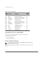
1
SummitGbX™ Installation
and User Guide
Extreme Networks, Inc.
3585 Monroe Street
Santa Clara, California 95051
(888) 257-3000
http://www.extremenetworks.com
Published: September 1999
Part number: 120040-00 rev. A
Copyright © Extreme Networks, Inc., 1998. All rights reserved. No part of this documentation may be
reproduced in any form or by any means or used to make any derivative work (such as translation,
transformation, or adaptation) without permission from Extreme Networks, Inc.
Extreme Networks, Summit, SummitGbX, and the Extreme Networks logo are trademarks of Extreme
Networks.
All other brand and product names are registered trademarks or trademarks of their respective
holders.
ii
SummitGbX™ Installation and
User Guide
This document describes the features and installation of the Summit™ Gigabit Ethernet
Fiber-Optic Extender (GbX).
SUMMITGbX OVERVIEW
The SummitGbX Gigabit Ethernet Fiber Optic Extender greatly increases the maximum
single mode fiber interconnect distance between Gigabit Ethernet switches from the
standard IEEE 802.3z distance of 500 meters to 80 km (50 miles), or more. The
attenuation characteristics of the installed fiber plant determine the maximum distance
that can be achieved. Links beyond 100 km are possible using an optical amplifier
option.
The SummitGbX is fully compatible with the Gigabit Ethernet IEEE 802.3z standard for
fiber optic interfaces.
Network management and loopback control functions are provided by an RS-232c port.
The SummitGbX supports full duplex operation as defined in IEEE 802.3x. This results
in 2 Gbps of actual link bandwidth, and provides lower latency, due to simultaneous
transmit and receive operations.
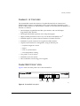
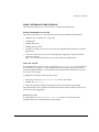
Figure 1 shows how the SummitGbX Extender offers network planners an important,
and fundamentally different, way to configure Gigabit Ethernet network by giving users
interconnect distances up to 100 km. In most cases, the SummitGbX allows much
greater freedom in the use of Summit and BlackDiamond™ switches, as distance
limitations cease to be a factor.
Summit GbX Installation and User Guide
1
SummitGbX Overview
Building 1
MMF
SX Ports
LDI Port
LDI Port
SX Port
SMF
SX Port
Building 2
GbX_cnx
Figure 1: SummitGbX used in a typical configuration
2
Summit GbX Installation and User Guide
Summary of Features
SUMMARY
OF
FEATURES
The SummitGbX extends the distance of Gigabit Ethernet links on Summit and
BlackDiamond switches to 80 kilometers using single mode fiber. Depending on the
quality of fiber, distances of 100 kilometers, or more, can be achieved. The summary of
features is as follows:
• One full-duplex Gigabit Ethernet fiber optic interface and one full-duplex
long-distance fiber interface
• Full-duplex bandwidth operation with 2 Gbps throughput
• Highly reliable performance and a very low Bit Error Rate (BER) of 10-12
• Standard duplex SC optical connector interface to Summit switches
• Standard SC optical connector for long-distance fiber interface
• Graphical user interface for management, using an RS-232c port
— Loopback diagnostic control
— Signal
— Loss of synchronization
— Over-temperature warning
• Low profile, 1U (1.75 inches)
• Standard 19-inch rack mount
• Dual, redundant, load sharing power supplies
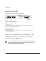
SUMMITGbX FRONT VIEW
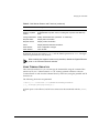
Figure 2 shows the front panel view of the SummitGbX.
RX
FLT
LDI OPTICAL PORT
TX
RX
SYNC LOOP
LOSS BACK
LDI
GBE
GBE OPTICAL PORT
TX
CLASS 1 LASER
CLASS 1 LASER
POWER
RX
TEMP
LDI OPTICAL PORT
LDI ports
Status
LEDs
Gigabit
port
TX
RX
CLASS 1 LASER
GbX_fr
Figure 2: SummitGbX front panel
Summit GbX Installation and User Guide
3
SummitGbX Front View
PORTS
The SummitGbX has one 1000BASE-SX port for connecting the SummitGbX to a
Summit or BlackDiamond switch, and one single mode long-distance interface (LDI) for
connecting between two SummitGbX units. Each 1000BASE-SX and LDI port has one
optical transmitter interface (TX) and one optical receiver interface (RX).
LEDS
Table 1 describes the LED behavior on the SummitGbX.
Table 1: SummitGbX LEDs
LED
Color
Indicates
RX FLT
(Receive Fault)
Green
Signal received
Yellow
No signal received
SYNC LOSS
Green
(Synchronization Loss)
Yellow
Receive clock detected
LOOP BACK
Green
In normal mode (no loopback)
Yellow
Loopback mode
POWER
Green
Power on
TEMP
Green
SummitGbX temperature normal
Yellow
SummitGbX indicating an overheat condition
MEDIA TYPES
AND
Receive clock not detected
DISTANCES
Supported media types and distances are described in Table 2.
Table 2: Media Types and Distances
Media Type
Standard
Media
Guaranteed Distance
850nm Multimode
Optics
1000BASE-SX
50/125um Multimode Fiber
(500/500 MHz–km)
550 Meters
62.5/125um Multimode Fiber
(160/500 MHz–km)
220 Meters
62.5/125um Multimode Fiber
(200/500 MHz–km)
275 Meters
4
Summit GbX Installation and User Guide
SummitGbX Front View
Table 2: Media Types and Distances (continued)
Media Type
Standard
1550nm Single mode
Optics
Media
Guaranteed Distance
10u Single mode Fiber
100 Kilometers
LONG DISTANCE INTERFACES
Table 3 describes the Long Distance Interface (LDI) specifications.
Table 3: LDI Specifications
Parameter
Minimum
Typical
Maximum
Optical Output Power
0dBm
1dBm
See Note 1
Optical ExtinctionRatio
7dB
Center Wavelength
1530nm
1550nm
1565nm
Optical Rise/Fall Time
0.5ns
-34dBm
-32dBm
LDI Optical Transceiver
LDI Optical Receiver
Optical Input Power Sensitivity
Optical Input Power Maximum
-8dBm
Operating Wavelength
1200nm
Optical Return Loss
27dB
1550nm
1600nm
Note 1: The transmitter output power level for the SummitGbX is +1dBm. The maximum allowable
receiver input power level is -8dBm. Therefore, there is a minimum of 9dB loss required for the link
to operate error-free. This minimum required loss can be achieved using a fiber length of 40 km
(0.25 dB/km provides 10dB loss), or by adding 10dB of fixed optical attenuator at the receiver end.
Summit GbX Installation and User Guide
5
SummitGbX Rear View
SUMMITGbX REAR VIEW
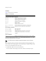
Figure 3 shows the rear panel view of the SummitGbX.
THIS DEVICE COMPLIES WITH PART 15 OF THE FFC RULES.
OPERATION IS SUBJECT TO THE FOLLOWING TWO
CONDITIONS: (1) THIS DEVICE MAY NOT CAUSE HARMFUL
INTERFERENCE, AND (2) THIS DEVICE MUST ACCEPT ANY
INTERFERENCE RECEIVED, INCLUDING INTERFERENCE THAT
MAY CAUSE UNDESIRED OPERATION. THIS PRODUCT CONFORMS
TO DHHS CFR21 SUBCHPT J. THIS DEVICE IS A CLASS 1 LASER.
GbX MGMT PORT
R3-232C
Made in U.S.A.
3.16T AMP FUSE
Model No. : 10922
Part No. : 800024-00-A
Serial No. : XXXXX-XXXXX
3.16T AMP FUSE
This version per fax from Diana Miller, 24 April 1998
and phone call 28/4/98
Console
port
GbX_rear
Figure 3: SummitGbX rear panel
POWER SOCKET
The SummitGbX automatically adjusts to the supply voltage. The power supply is
autoranging from 100 VAC to 240 VAC.
MANAGEMENT PORT
The console port (9-pin, D-type connector) is used to connect a terminal for local,
out-of-band management.
INSTALLING
AND
PREPARING
THE
SUMMITGbX
FOR
USE
The SummitGbX can be mounted in a rack, or placed free-standing on a tabletop.
PREPARING
THE
SUMMIT GbX
FOR
USE
To ensure safe operation of this equipment and personnel using this equipment,
the cautions and warnings in this manual must be followed. This equipment has
been manufactured and tested according to international safety standards. There
are no user-serviceable parts in the SummitGbX.
6
Summit GbX Installation and User Guide
Installing and Preparing the SummitGbX for Use
INITIAL INSPECTION
If the shipping container shows signs of damage, keep it, and all packing materials,
until the SummitGbX has been thoroughly tested and verified. Verify that all contents
are complete, according to the list below:
• SummitGbX in electro-static discharge (ESD) bag
• 19-inch rack mount kit
• Summit GbX Installation and User Guide (this document)
• Power cords (2)
• Software diskette
If any contents are found missing, or if the SummitGbX is found to be damaged, contact
Extreme Networks immediately for assistance.
POWER REQUIREMENTS
The SummitGbX is designed to accept 100 to 240 VAC, 50 to 60 Hz main power. The
SummitGbX automatically senses and adjusts for the proper AC voltage level.
Failure to properly ground the SummitGbX can result in personal injury or
equipment damage. Connect the power cord only to a receptacle with a
protective safety ground. Do not defeat the earth grounding protection by using
an extension cord or other device that defeats the safety ground connection.
OPERATING ENVIRONMENT REQUIREMENTS
The SummitGbX is designed to operate in a 10 to 50 degree C ambient environment. Do
not restrict the air intake or exhaust vents.
Obstructing the air intake or exhaust of the SummitGbX may produce internal
temperatures leading to device failure. Do not block the intake or exhaust of the
unit. Do not operate the unit outside its specified temperature range.
Summit GbX Installation and User Guide
7
Installing and Preparing the SummitGbX for Use
RACK MOUNTING
The SummitGbX is 1U (1.75 inches) high and fits in a standard 19-inch rack.
To rack mount the SummitGbX, follow these steps:
1 Place the SummitGbX on a hard flat surface with the front facing toward you.
2 Remove the existing screws from the left and right sides of the chassis and keep the
screws for Step 4.
3 Locate one of the mounting brackets over the mounting holes on the left side of the
unit.
4 Insert the four screws and fully tighten, using a suitable screwdriver.
5 Repeat Steps 3 and 4 for the right side of the SummitGbX.
6 Insert the SummitGbx into the 19-inch rack and secure the rack mount brackets with
suitable screws (not provided). Ensure that ventilation holes are not obstructed.
7 Connect the cables.
FREE-STANDING
The SummitGbX is supplied with four self-adhesive rubber feet. Apply the rubber feet
to the underside of the device by sticking one at each corner of the switch.
CONNECTING
TO
OTHER DEVICES
To install the SummitGbX, follow these steps:
1 Mount the SummitGbX in the equipment rack, or, if the SummitGbX will be located
on a table, place the rubber feet on the bottom of the SummitGbX.
2 Connect the 1000BASE-SX port on the first SummitGbX to a Gigabit Ethernet port on
a Summit or BlackDiamond switch, using a multimode (MMF) cable.
3 Connect the first SummitGbX to a second SummitGbX, using LDI ports and single
mode fiber (SMF) cables with SC simplex connectors.
4 Connect the 1000BASE-SX port on the second SummitGbX to a Gigabit Ethernet port
on a second Summit or BlackDiamond switch, using a multimode fiber (MMF) cable.
8
Summit GbX Installation and User Guide
Installing and Preparing the SummitGbX for Use
POWERING ON
THE
SUMMITGbX
To turn on power to the SummitGbX, connect the power cable to the SummitGbX and
then to the wall outlet. Turn the On/Off switch to the On position.
CONNECTING EQUIPMENT
TO THE
SUMMITGbX CONSOLE PORT
Connection to the console port, located on the rear of the unit, is used for direct local
management. The SummitGbX console port settings are set as follows:
• Baud rate — 9600
• Data bits — 8
• Stop bit — 1
• Parity — None
• Flow control — XON/XOFF
The terminal connected to the console port must be configured as a VT-100 terminal,
with the same settings. This procedure is described in the documentation supplied with
the terminal.
Ensure that text wrapping is disabled, and local echo text is enabled on your
terminal.
Appropriate cables are available from your local supplier. To make your own cables,
pin-outs for a DB-9 male console connector are described in Table 4.
Table 4: Console Connector Pin-Outs
Function
Pin Number
TXD (transmit data)
3
RXD (receive data)
2
GND (ground)
5
Summit GbX Installation and User Guide
9
Managing the SummitGbX
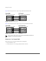
Figure 4 shows the pin-outs for a 9-pin to 25-pin (RS-232) null-modem cable.
SummitGbX
PC/Terminal
Cable connector: 9-pin female
Cable connector: 25-pin male/female
1
3
2
7
Screen Shell
3
TxD
2
RxD
5
Ground
Screen
RxD
TxD
Ground
pin_GbX1
Figure 4: Null-modem cable pin-outs
Figure 5 shows the pin-outs for a 9-pin to 9-pin (PC-AT) null-modem serial cable.
SummitGbX
PC-AT Serial Port
Cable connector: 9-pin female
Cable connector: 9-pin female
Shell Screen
2
RxD
3
TxD
5
Ground
Screen Shell
3
TxD
2
RxD
5
Ground
pin_GbX2
Figure 5: PC-AT serial null-modem cable pin-outs
The null modem cable used for other Summit and BlackDiamond switches is
compatible for use with the SummitGbX.
MANAGING
THE
SUMMITGbX
There are two ways to access the SummitGbX for management:
• The GUI installed on a PC.
• A VT100 terminal or a PC running terminal emulation software.
10
Summit GbX Installation and User Guide
Managing the SummitGbX
USING
THE
GRAPHIC USER INTERFACE
This section describes how to use the GUI to manage the SummitGbX.
SYSTEM
REQUIREMENTS FOR THE
GUI
The GUI can be loaded on a PC that meets the following minimum requirements:
• Windows 95 or Windows NT version 4.0
• 64 MB RAM
• 100 MB disk space
• 200 Mhz Pentium CPU
• 1.44 Mb 3.5" floppy drive (if you are using the supplied floppy diskette to load the
application)
• A network connection (if you are downloading the application from the Extreme
Networks web site:
http://www.extremenetworks.com/extreme/support/installgbx.htm )
INSTALLING
THE
GUI
To install the GUI on your PC, first copy the file SummitGbX_GUI.zip into any folder on
the hard disk (for example, a newly created SummitGbX folder.) Either copy the file
from the supplied diskette, or download the file from the Extreme Networks web site,
and save it to the folder.
Complete the installation following these steps:
• Unzip the contents of SummitGbX_GUI.zip into the same folder.
• Double-click setup.exe.
• Follow the prompts, filling in appropriate system and directory information.
The MonitorGbX icon is created on the Microsoft Office toolbar. Double-click this icon
to launch the GUI application.
REMOVING
THE
GUI
To uninstall the GUI, use Add/Remove Programs from the control panel. Then,
manually delete any remaining files from the folder.
Summit GbX Installation and User Guide
11
Managing the SummitGbX
USING
THE
GUI
To launch the GUI application, double-click the MonitorGbX icon from the Office
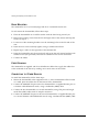
toolbar. The GbX Monitor window appears, as shown in Figure 6.
Figure 6: GbX Monitor window
The GbX Monitor buttons are described in Table 5.
Table 5: GbX Monitor Buttons and Functions
Button
Description
Com1
Connect GbX Monitor on Com1 to SummitGbX.
Com2
Connect GbX Monitor on Com2 to SummitGbX.
Disconnect
Disconnect GbX Monitor.
Login
Log in to SummitGbX.
Logout
Log out of SummitGbX.
Modify Login
Modify login name and password (maximum 15 characters).
12
Summit GbX Installation and User Guide
Managing the SummitGbX
Table 5: GbX Monitor Buttons and Functions (continued)
Button
Description
Model Info
Display SummitGbX model information.
Display Loop Back
Control
Enable/disable loop back control, including LDI loop back and GBE loop
back.
Change GbX Name
Modify SummitGbX name (maximum 11 characters).
Request Status
Display status information.
Request Version
Display version information.
About
Display Extreme Networks information.
Save Window
Save configuration changes
Clear Window
Clear window.
By default, the login user name is admin, and the default password is admin. The login
name and password are case sensitive.
When enabling the loopback mode on any interface, disable the Gigabit Ethernet
ports on all connected Summit switches.
USING TERMINAL EMULATION
This section describes how you can manage the SummitGbX using the command line
interface (CLI) via a VT100 terminal, or a PC running terminal emulation software.
Communication to and from the SummitGbX is by ASCII text, using the printable ASCII
character set.
The following characters are permitted:
!"#$%&'()*+-./0123456789:;<=>?@ABCDEFGHIJKLMNOPQRSTUVWXYZ
[\]^_`abcdefghijklmnopqrstuvwxyz{|}~
A blank space is also allowed, and all user entries must be terminated with the [Enter]
key.
Summit GbX Installation and User Guide
13
Managing the SummitGbX
COMMANDS
Table 6 describes the CLI commands.
Table 6: CLI Commands
Command
Description
Configuration/Status Mode Commands
CMD GLE
Enable Gigabit Ethernet loopback.
CMD GLD
Disable Gigabit Ethernet loopback.
CMD LLE
Enable long distance loopback.
CMD LLD
Disable long distance loopback.
CMD RS?
Request status.
CMD V?
Request software version.
CMD ID xxxxxxxxxxx
Set unit identification (maximum 11 Characters)
CMD I?
Display the factory model and serial numbers.
Password Mode Commands
CMD USR xxxxxx
Enter login name.
CMD PAS xxxxxx
Enter password.
CMD CUSR xxxxxx
Change login name (maximum 15 characters)
CMD CPAS xxxxxx
Change password (maximum 15 characters).
CMD LOG
Logout.
Version Commands
CMD V?
Displays unit identification and software version number.
The factory default login user name is admin and the default password is admin. The
login name and password are case sensitive.
If VT-100 local echo is enabled, the typed text appears on the local screen.
The first time the system is powered on with the terminal connection plugged in, the
factory default status message appears. Press the [Enter] key to display the login screen.
To log in to the SummitGbX, follow these steps:
1 Type CMD USR admin, followed by the [Enter] key.
The cursor blinks at the left edge of the screen, under the command just typed.
14
Summit GbX Installation and User Guide
Managing the SummitGbX
2 Type CMD PAS admin, followed by the [Enter] key.
The screen displays login complete.
STATUS
Status messages are sent under several circumstances:
• When an error condition occurs.
• When an error condition clears.
• Approximately every 15 minutes.
• When requested by the user.
• When power is applied to the unit.
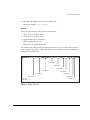
The format of the status message is identical in all cases. Figure 7 shows the format of a
status response and Table 7 gives a description of each field. The columns identified by
number hold variable data.
Courier New, Reg. :
to outline
COLUMN 60
COLUMN 72
COLUMN 83
COLUMN 47
COLUMN 36
COLUMN 24
UNIT ID
COLUMNS 1-11
COLUMN 88
COLUMN 95
COLUMN 102
COLUMN 104
GbX_stat
Figure 7: Status response
Summit GbX Installation and User Guide
15
Troubleshooting the SummitGbX
Table 7: Status Field Descriptions
Column
Location Field Text
Description
Status
Column
1-11
User Defined
SummitGbX ID
NA
13-15
GBE
Gigabit Ethernet Interface
NA
17-24
RX FLT
RX fault (low optical input power)
24
26-36
SYNC LOSS
Sync loss (clock recovery failure)
36
38-47
LOOPBACK
Loopback enabled
47
49-51
LDI
Long distance interface
NA
53-60
RX FLT
RX fault (low optical input power)
60
62-72
SYNC LOSS
Sync loss (clock recovery failure)
72
74-83
LOOPBACK
Loopback enabled
83
85-88
TF
Temperature fault, chassis
88
90-95
PS1F
Power supply 1 fault
95
97-102
PS2F
Power supply 2 fault
102
104-xx
Variable
Comment field
NA
END
<LF><CR>
Message terminator
NA
TROUBLESHOOTING
THE
SUMMITGbX
This section describes troubleshooting procedures for the SummitGbX:
• Cleaning the optical connector
• Troubleshooting the link
• Loopback troubleshooting
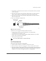
OPTICAL CONNECTOR CLEANING
Connecting damaged or dirty optical fibers to the SummitGbX will damage the
connectors and the internal optics.
The following steps describe the procedure for cleaning an optical connector, shown in
Figure 8.
16
Summit GbX Installation and User Guide
Troubleshooting the SummitGbX
1 Using filtered, compressed air, blow any dust out of the female connector mounted
on the SummitGbx.
2 Wipe the tip and sheath of the optical fiber cable (located on the cable connector)
with an optical swab that is moistened with optical grade isopropyl alcohol.
3 Wipe the tip and sheath of the optical fiber cable (located on the cable connector)
with a dry optical swab.
4 Blow dry with filtered, compressed air.
Optical connector
on SummitGbX
Optical fiber
cable tip
Optical connector
on cable end
GbX_OCC
Figure 8: Optical connectors
Listed below are the suggested cleaning materials and sources:
• Compressed gas aerosol can, such as Chemtronics, Inc. (800-645-5244,
www.chemtronics.com) product: 70 PSI
• Lint free swab, such as The Texwipe Company (Upper Saddle River, N.J. 07458)
product: Micro Absorbond Swab TX759B
• Optical grade isopropyl alcohol
Do not use rubbing alcohol. It contains 30% water.
LINK TROUBLESHOOTING
Follow these steps to help detect a link problem:
1 Clean the optical connectors, as described in the previous section.
2 Make sure that the connectors are plugged in correctly on both ends of the link.
3 Verify that the RX FLT LEDs (GBE and LDI) on the SummitGbX chassis are green on
both ends of the link. An RX fault can be caused by incorrectly connected fibers (for
example, TX-to-TX,) dirty or damaged connectors, or damaged fiber.
Summit GbX Installation and User Guide
17
Troubleshooting the SummitGbX
4 Using an optical power meter, select the appropriate wavelength (780, 1310,
1550 nm) and measure the input power at the ports. Power levels should be above
the minimum specified in Table 3. Optical levels should operate about 3dBm greater
than minimum levels to provide extra link margin.
5 Check the color of SYNC LOSS LEDs. If one of the SYNC LOSS LEDs is yellow, the
Clock/Data Recovery (CDR) was unsuccessful in retiming the data at that input
port. This can be caused by incorrect data rate (for example, 10/100 Mbps), poor
signal quality (excessive jitter), or by a component failure.
6 Follow the loopback troubleshooting procedure, described in the next section.
Never look directly into an optical connector, or through optical instruments or
lenses, to detect presence of light.
LOOPBACK TROUBLESHOOTING
The purpose of the loopback troubleshooting procedure is to loopback data at various
stages of the link, in order to isolate fault problems. Loopback can be performed
electrically within the SummitGbX, and optically between SummitGbXs. Both methods
are described in this procedure. By examining the hardware included or excluded with
each step, the fault can be isolated to a single piece of equipment or fiber.
The following steps describe the loopback procedure for the SummitGbx, starting on the
end of the link near you. The entire procedure can also be reversed, to start with the
SummitGbX on the remote end of the link. Clean optical connectors before every
connection.
Use one of these methods to verify the outcome of loopback troubleshooting steps:
• The terminal screen, if you are using a serial connection.
• The GUI, if you are using the GUI software.
• The front panel LEDs of the SummitGbX.
1 Using multimode fiber jumper(s), connect the Host’s GBE TX and RX ports.
2 Reconnect the Host’s GBE ports to the SummitGbX GBE port. Verify GBE LoopBack
Enabled status. The GBE Loop Back LED should be yellow.
3 Using the management interface, disable GBE Loopback. Verify Loopback Disabled
status. The GBE Loop Back LED should be green. Connect the SummitGbX LDI TX
output to its LDI RX input using single mode fiber (an optical in-line attenuator is
required for 80 km version only.) Verify optical power at RX.
18
Summit GbX Installation and User Guide
Technical Specifications
4 Reconnect the SummitGbX LDI ports to the optical plant. Using the management
interface of the remote SummitGbX, enable LDI Loopback. Verify Loopback Enabled
status. The LDI Loop Back LED should be yellow.
5 Using the management interface of the remote SummitGbX, disable LDI Loopback.
Verify Loopback Disabled status. The LDI Loop Back LED should be green. Connect
the remote SummitGbX GBE TX output to the same SummitGbX RX input using
multimode fiber.
6 Using multimode fiber jumper(s), connect the remote Host’s GBE TX and RX ports.
SummitGbX inputs and outputs are susceptible to damage through electro-static
discharge (ESD). Always use ESD control measures when operating the unit.
TECHNICAL SPECIFICATIONS
The following tables list the technical specifications for the SummitGbX.
Physical Dimensions
Height: 1.75 inches (4.45 cm) x Width: 19 inches (48.26
cm) x Depth: 15 inches (38.14 cm)
Weight: 7.5 lbs. (2.5 kg)
Environmental Requirements
Operating temperature
0° C to 50° C
Storage temperature
-10 ° C to 70 ° C
Operating humidity
10% to 95% relative humidity, noncondensing
Standards
EN60068 (IEC68)
Safety
Agency certifications
cUL listed to CSA C22.2 #950; 95
Electromagnetic Compatibility
FCC part 15 Class A
CE Mark
Power Supply
AC line frequency
50/60Hz
Input voltage options
100VAC to 240VAC auto-switching
Power rating
50 watts
Summit GbX Installation and User Guide
19