1
Cisco Catalyst Blade Switch 3130 and
3032 for Dell Command Reference
Cisco IOS Release 12.2(58)SE
April 2011
Americas Headquarters
Cisco Systems, Inc.
170 West Tasman Drive
San Jose, CA 95134-1706
USA
http://www.cisco.com
Tel: 408 526-4000
800 553-NETS (6387)
Fax: 408 527-0883
Text Part Number: OL-13271-06
THE SPECIFICATIONS AND INFORMATION REGARDING THE PRODUCTS IN THIS MANUAL ARE SUBJECT TO CHANGE WITHOUT NOTICE. ALL
STATEMENTS, INFORMATION, AND RECOMMENDATIONS IN THIS MANUAL ARE BELIEVED TO BE ACCURATE BUT ARE PRESENTED WITHOUT
WARRANTY OF ANY KIND, EXPRESS OR IMPLIED. USERS MUST TAKE FULL RESPONSIBILITY FOR THEIR APPLICATION OF ANY PRODUCTS.
THE SOFTWARE LICENSE AND LIMITED WARRANTY FOR THE ACCOMPANYING PRODUCT ARE SET FORTH IN THE INFORMATION PACKET THAT
SHIPPED WITH THE PRODUCT AND ARE INCORPORATED HEREIN BY THIS REFERENCE. IF YOU ARE UNABLE TO LOCATE THE SOFTWARE LICENSE
OR LIMITED WARRANTY, CONTACT YOUR CISCO REPRESENTATIVE FOR A COPY.
The Cisco implementation of TCP header compression is an adaptation of a program developed by the University of California, Berkeley (UCB) as part of UCB’s public
domain version of the UNIX operating system. All rights reserved. Copyright © 1981, Regents of the University of California.
NOTWITHSTANDING ANY OTHER WARRANTY HEREIN, ALL DOCUMENT FILES AND SOFTWARE OF THESE SUPPLIERS ARE PROVIDED “AS IS” WITH
ALL FAULTS. CISCO AND THE ABOVE-NAMED SUPPLIERS DISCLAIM ALL WARRANTIES, EXPRESSED OR IMPLIED, INCLUDING, WITHOUT
LIMITATION, THOSE OF MERCHANTABILITY, FITNESS FOR A PARTICULAR PURPOSE AND NONINFRINGEMENT OR ARISING FROM A COURSE OF
DEALING, USAGE, OR TRADE PRACTICE.
IN NO EVENT SHALL CISCO OR ITS SUPPLIERS BE LIABLE FOR ANY INDIRECT, SPECIAL, CONSEQUENTIAL, OR INCIDENTAL DAMAGES, INCLUDING,
WITHOUT LIMITATION, LOST PROFITS OR LOSS OR DAMAGE TO DATA ARISING OUT OF THE USE OR INABILITY TO USE THIS MANUAL, EVEN IF CISCO
OR ITS SUPPLIERS HAVE BEEN ADVISED OF THE POSSIBILITY OF SUCH DAMAGES.
Cisco and the Cisco Logo are trademarks of Cisco Systems, Inc. and/or its affiliates in the U.S. and other countries. A listing of Cisco's trademarks can be found at
www.cisco.com/go/trademarks. Third party trademarks mentioned are the property of their respective owners. The use of the word partner does not imply a partnership
relationship between Cisco and any other company. (1005R)
Any Internet Protocol (IP) addresses used in this document are not intended to be actual addresses. Any examples, command display output, and figures included in the
document are shown for illustrative purposes only. Any use of actual IP addresses in illustrative content is unintentional and coincidental.
Cisco Catalyst Blade Switch 3130 and 3032 for Dell Command Reference
©2007–2011 Cisco Systems, Inc. All rights reserved.
C O N T E N T S
Preface
xxi
Audience
Purpose
xxi
xxi
Conventions
xxi
Related Publications
xxii
Obtaining Documentation and Submitting a Service Request
CHAPTER
1
Using the Command-Line Interface
Accessing the Switch
xxiii
1-1
1-1
CLI Command Modes 1-2
User EXEC Mode 1-3
Privileged EXEC Mode 1-3
Global Configuration Mode 1-4
Interface Configuration Mode 1-4
VLAN Configuration Mode 1-4
Line Configuration Mode 1-5
CHAPTER
2
Cisco Catalyst Blade Switch 3130 for Dell Cisco IOS Commands
aaa accounting dot1x
2-1
aaa authentication dot1x
2-3
aaa authorization network
action
2-1
2-5
2-6
archive copy-sw
2-8
archive download-sw
archive tar
2-11
2-15
archive upload-sw
arp access-list
2-18
2-20
authentication command bounce-port ignore
2-22
authentication command disable-port ignore
2-23
authentication control-direction
authentication event
authentication fallback
2-24
2-26
2-30
Cisco Catalyst Blade Switch 3130 and 3032 for Dell Command Reference
OL-13271-06
iii
Contents
authentication host-mode
2-32
authentication mac-move permit
authentication open
2-36
authentication order
2-38
authentication periodic
2-40
authentication port-control
authentication priority
authentication timer
auto qos trust
2-46
2-48
2-50
2-53
auto qos video
2-56
auto qos voip
2-59
boot auto-copy-sw
2-66
boot auto-download-sw
boot buffersize
2-70
boot config-file
2-71
boot enable-break
boot helper
2-68
2-72
2-73
boot helper-config-file
boot manual
2-74
2-75
boot private-config-file
boot system
2-79
channel-protocol
class
2-76
2-77
channel-group
cisp enable
2-42
2-44
authentication violation
auto qos classify
2-34
2-83
2-84
2-85
class-map
clear dot1x
clear eap
2-88
2-90
2-91
clear errdisable interface
2-92
clear ip arp inspection log
2-93
clear ip arp inspection statistics
clear ip dhcp snooping
2-95
clear ip dhcp snooping
2-97
2-94
Cisco Catalyst Blade Switch 3130 and 3032 for Dell Command Reference
iv
OL-13271-06
Contents
clear ipc
2-99
clear ipv6 dhcp conflict
2-100
clear l2protocol-tunnel counters
clear lacp
2-101
2-102
clear logging
2-103
clear mac address-table
2-104
clear mac address-table move update
clear nmsp statistics
clear pagp
2-105
2-106
2-107
clear port-security
2-108
clear psp counter
2-110
clear spanning-tree counters
2-111
clear spanning-tree detected-protocols
clear vmps statistics
clear vtp counters
2-113
2-114
copy logging onboard
2-115
define interface-range
delete
2-112
2-117
2-119
deny (ARP access-list configuration)
2-120
deny (IPv6 access-list configuration)
2-122
deny (MAC access-list configuration)
diagnostic monitor
2-130
diagnostic schedule
diagnostic start
dot1x
2-127
2-132
2-134
2-137
dot1x auth-fail max-attempts
dot1x auth-fail vlan
2-139
2-141
dot1x control-direction
2-143
dot1x credentials (global configuration)
dot1x critical (global configuration)
dot1x critical (interface configuration)
dot1x default
2-145
2-146
2-148
2-150
dot1x fallback
2-151
dot1x guest-vlan
2-152
dot1x host-mode
2-154
Cisco Catalyst Blade Switch 3130 and 3032 for Dell Command Reference
OL-13271-06
v
Contents
dot1x initialize
2-155
dot1x mac-auth-bypass
dot1x max-reauth-req
dot1x max-req
dot1x pae
2-156
2-158
2-160
2-161
dot1x port-control
2-162
dot1x re-authenticate
2-164
dot1x reauthentication
2-165
dot1x supplicant force-multicast
dot1x timeout
2-167
dot1x violation-mode
duplex
2-166
2-170
2-172
epm access-control open
errdisable detect cause
2-174
2-175
errdisable detect cause small-frame
errdisable recovery
2-179
errdisable recovery cause small-frame
exception crashinfo
fallback profile
2-186
hw-module
2-188
2-183
interface port-channel
interface range
2-190
2-192
interface vlan
2-194
ip access-group
ip admission
2-182
2-184
flowcontrol
ip address
2-177
2-196
2-199
2-201
ip admission name proxy http
ip arp inspection filter vlan
ip arp inspection limit
2-204
2-206
ip arp inspection log-buffer
ip arp inspection trust
2-208
2-210
ip arp inspection validate
ip arp inspection vlan
2-202
2-212
2-214
ip arp inspection vlan logging
2-215
Cisco Catalyst Blade Switch 3130 and 3032 for Dell Command Reference
vi
OL-13271-06
Contents
ip device tracking
2-217
ip device tracking maximum
ip device tracking probe
ip dhcp snooping
2-218
2-219
2-221
ip dhcp snooping binding
2-222
ip dhcp snooping database
2-224
ip dhcp snooping information option
2-226
ip dhcp snooping information option allow-untrusted
ip dhcp snooping information option format remote-id
ip dhcp snooping limit rate
ip dhcp snooping trust
2-228
2-230
2-231
2-232
ip dhcp snooping verify
ip dhcp snooping vlan
2-233
2-234
ip dhcp snooping vlan information option format-type circuit-id string
ip igmp filter
2-237
ip igmp max-groups
ip igmp profile
2-239
2-241
ip igmp snooping
2-243
ip igmp snooping last-member-query-interval
ip igmp snooping querier
ip igmp snooping tcn
2-249
2-251
ip igmp snooping tcn flood
2-253
ip igmp snooping vlan immediate-leave
ip igmp snooping vlan mrouter
ip igmp snooping vlan static
ip snap forwarding
ip source binding
2-245
2-247
ip igmp snooping report-suppression
ip ssh
2-235
2-254
2-255
2-257
2-259
2-260
2-262
ip sticky-arp (global configuration)
2-264
ip sticky-arp (interface configuration)
ip verify source
2-268
ipv6 access-list
2-270
ipv6 address dhcp
2-266
2-272
ipv6 dhcp client request vendor
2-273
Cisco Catalyst Blade Switch 3130 and 3032 for Dell Command Reference
OL-13271-06
vii
Contents
ipv6 dhcp ping packets
ipv6 dhcp pool
2-274
2-276
ipv6 dhcp server
2-278
ipv6 mld snooping
2-280
ipv6 mld snooping last-listener-query-count
ipv6 mld snooping last-listener-query-interval
2-282
2-284
ipv6 mld snooping listener-message-suppression
ipv6 mld snooping robustness-variable
ipv6 mld snooping tcn
2-292
2-294
l2protocol-tunnel
2-296
l2protocol-tunnel cos
lacp port-priority
2-299
2-300
lacp system-priority
link state group
2-302
2-304
link state track
2-306
location (global configuration)
2-307
location (interface configuration)
logging file
2-309
2-311
mab request format attribute 32
mac access-group
2-313
2-315
mac access-list extended
2-317
mac address-table aging-time
2-319
mac address-table learning vlan
2-320
mac address-table move update
2-322
mac address-table notification
mac address-table static
2-332
2-333
macro global description
macro name
2-327
2-329
macro description
macro global
2-324
2-326
mac address-table static drop
macro apply
2-288
2-290
ipv6 mld snooping vlan
ipv6 traffic-filter
2-286
2-336
2-337
match (access-map configuration)
2-339
Cisco Catalyst Blade Switch 3130 and 3032 for Dell Command Reference
viii
OL-13271-06
Contents
match (class-map configuration)
mdix auto
mls qos
2-341
2-344
2-346
mls qos aggregate-policer
mls qos cos
2-350
mls qos dscp-mutation
mls qos map
2-348
2-352
2-354
mls qos queue-set output buffers
2-358
mls qos queue-set output threshold
mls qos rewrite ip dscp
2-360
2-362
mls qos srr-queue input bandwidth
mls qos srr-queue input buffers
2-364
2-366
mls qos srr-queue input cos-map
2-368
mls qos srr-queue input dscp-map
2-370
mls qos srr-queue input priority-queue
2-372
mls qos srr-queue input threshold
2-374
mls qos srr-queue output cos-map
2-376
mls qos srr-queue output dscp-map
mls qos trust
2-378
2-380
mls qos vlan-based
monitor session
2-382
2-383
mvr (global configuration)
2-387
mvr (interface configuration)
network-policy
2-390
2-392
network-policy profile (global configuration)
2-393
network-policy profile (network-policy configuration)
nmsp
2-396
nmsp attachment suppress
2-397
no authentication logging verbose
no dot1x logging verbose
no mab logging verbose
nsf
2-394
2-398
2-399
2-400
2-401
pagp learn-method
pagp port-priority
2-403
2-405
permit (ARP access-list configuration)
2-407
Cisco Catalyst Blade Switch 3130 and 3032 for Dell Command Reference
OL-13271-06
ix
Contents
permit (IPv6 access-list configuration)
2-409
permit (MAC access-list configuration)
police
2-417
police aggregate
policy-map
2-419
2-421
port-channel load-balance
priority-queue
private-vlan
psp
2-424
2-426
2-428
private-vlan mapping
2-431
2-433
queue-set
2-434
radius-server dead-criteria
radius-server host
reload
2-435
2-437
2-439
remote command
remote-span
2-441
2-443
renew ip dhcp snooping database
reserved-only
sdm prefer
2-449
2-450
service password-recovery
service-policy
session
setup
2-445
2-447
rmon collection stats
set
2-414
2-454
2-456
2-459
2-460
2-462
setup express
2-465
show access-lists
2-467
show archive status
2-470
show arp access-list
2-471
show authentication
2-472
show auto qos
show boot
2-476
2-480
show cable-diagnostics tdr
show cisp
2-483
2-485
show class-map
2-486
Cisco Catalyst Blade Switch 3130 and 3032 for Dell Command Reference
x
OL-13271-06
Contents
show controllers cpu-interface
2-487
show controllers ethernet-controller
2-489
show controllers ethernet-controller fastethernet
show controllers tcam
2-499
show controllers utilization
show diagnostic
2-501
2-503
show dot1q-tunnel
show dot1x
2-508
2-509
show dtp
2-513
show eap
2-515
show env
2-517
show errdisable detect
2-519
show errdisable flap-values
show errdisable recovery
show etherchannel
show flowcontrol
show idprom
2-521
2-522
2-524
show fallback profile
2-527
2-528
2-530
show interfaces
2-532
show interfaces counters
show inventory
2-544
2-546
show ip arp inspection
2-548
show ip dhcp snooping
2-552
show ip dhcp snooping binding
2-553
show ip dhcp snooping database
2-555
show ip dhcp snooping statistics
2-557
show ip igmp profile
show ip igmp snooping
2-560
2-561
show ip igmp snooping groups
2-564
show ip igmp snooping mrouter
show ip igmp snooping querier
show ip source binding
show ip verify source
show ipc
2-496
2-566
2-567
2-569
2-570
2-572
show ipv6 access-list
2-575
Cisco Catalyst Blade Switch 3130 and 3032 for Dell Command Reference
OL-13271-06
xi
Contents
show ipv6 dhcp conflict
2-577
show ipv6 mld snooping
2-578
show ipv6 mld snooping address
2-580
show ipv6 mld snooping mrouter
2-582
show ipv6 mld snooping querier
show ipv6 route updated
show l2protocol-tunnel
show lacp
2-584
2-586
2-588
2-590
show link state group
2-594
show location
2-596
show logging
2-598
show mac access-group
2-603
show mac address-table
2-604
show mac address-table address
2-606
show mac address-table aging-time
show mac address-table count
2-607
2-609
show mac address-table dynamic
2-610
show mac address-table interface
2-612
show mac address-table learning
2-613
show mac address-table move update
show mac address-table notification
show mac address-table static
2-619
2-621
show mls qos aggregate-policer
show mls qos input-queue
show mls qos interface
show mls qos maps
show mls qos vlan
show mvr
2-622
2-623
2-624
2-627
show mls qos queue-set
show monitor
2-615
2-617
show mac address-table vlan
show mls qos
2-614
2-630
2-631
2-632
2-634
show mvr interface
2-635
show mvr members
2-637
show network-policy profile
2-639
Cisco Catalyst Blade Switch 3130 and 3032 for Dell Command Reference
xii
OL-13271-06
Contents
show nmsp
2-640
show pagp
2-643
show parser macro
2-645
show policy-map
2-648
show port-security
show psp config
2-649
2-651
show psp statistics
show sdm prefer
2-652
2-653
show setup express
2-656
show spanning-tree
2-657
show storm-control
2-663
show switch
2-665
show system mtu
show udld
2-671
show version
show vlan
2-670
2-674
2-676
show vlan access-map
show vlan filter
show vmps
show vtp
shutdown
2-680
2-681
2-682
2-684
2-691
shutdown vlan
2-692
small-frame violation rate
2-693
snmp-server enable traps
snmp-server host
2-695
2-699
snmp trap mac-notification
2-703
spanning-tree backbonefast
spanning-tree bpdufilter
2-705
2-706
spanning-tree bpduguard
spanning-tree cost
2-708
2-710
spanning-tree etherchannel guard misconfig
spanning-tree extend system-id
spanning-tree guard
spanning-tree link-type
2-712
2-714
2-716
2-718
spanning-tree loopguard default
2-720
Cisco Catalyst Blade Switch 3130 and 3032 for Dell Command Reference
OL-13271-06
xiii
Contents
spanning-tree mode
2-722
spanning-tree mst configuration
spanning-tree mst cost
2-724
2-726
spanning-tree mst forward-time
spanning-tree mst hello-time
2-728
2-729
spanning-tree mst max-age
2-730
spanning-tree mst max-hops
2-731
spanning-tree mst port-priority
2-732
spanning-tree mst pre-standard
spanning-tree mst priority
spanning-tree mst root
2-734
2-735
2-736
spanning-tree port-priority
2-738
spanning-tree portfast (global configuration)
spanning-tree portfast (interface configuration)
spanning-tree transmit hold-count
spanning-tree uplinkfast
spanning-tree vlan
speed
2-743
2-745
2-746
2-748
2-751
srr-queue bandwidth limit
2-753
srr-queue bandwidth shape
2-755
srr-queue bandwidth share
2-757
stack-mac persistent timer
2-759
storm-control
switch
2-740
2-761
2-764
switch priority
2-766
switch provision
2-767
switch renumber
2-769
switchport
2-771
switchport access
2-773
switchport autostate exclude
switchport backup interface
switchport block
switchport host
switchport mode
2-775
2-777
2-780
2-782
2-783
switchport mode private-vlan
2-786
Cisco Catalyst Blade Switch 3130 and 3032 for Dell Command Reference
xiv
OL-13271-06
Contents
switchport nonegotiate
2-788
switchport port-security
2-790
switchport port-security aging
switchport priority extend
switchport private-vlan
switchport protected
switchport trunk
2-795
2-797
2-799
2-801
2-803
switchport voice detect
switchport voice vlan
2-806
2-807
system env temperature threshold yellow
system mtu
2-811
test cable-diagnostics tdr
traceroute mac
trust
2-819
udld
2-821
2-817
2-823
udld reset
vlan
2-813
2-814
traceroute mac ip
udld port
2-825
2-826
vlan access-map
2-831
vlan dot1q tag native
vlan filter
2-833
2-835
vmps reconfirm (privileged EXEC)
2-837
vmps reconfirm (global configuration)
vmps retry
vmps server
2-840
vtp (interface configuration)
vtp primary
A
2-838
2-839
vtp (global configuration)
APPENDIX
2-809
2-842
2-847
2-848
Cisco Catalyst Blade Switch 3130 for Dell Boot Loader Commands
arp
A-2
boot
cat
A-1
A-3
A-5
copy
delete
A-6
A-7
Cisco Catalyst Blade Switch 3130 and 3032 for Dell Command Reference
OL-13271-06
xv
Contents
dir
A-8
flash_init
format
A-10
A-11
fsck
A-12
help
A-13
memory
A-14
mgmt_clr
A-16
mgmt_init
A-17
mgmt_show
mkdir
A-19
more
A-20
rename
A-21
reset
A-22
rmdir
A-23
set
A-24
type
unset
A-27
A-28
version
APPENDIX
B
A-18
A-30
Cisco Catalyst Blade Switch 3130 for Dell Debug Commands
debug authentication
debug auto qos
debug dot1x
B-2
B-4
debug backup
debug cisp
B-6
B-7
B-8
debug dtp
B-9
debug eap
B-10
debug etherchannel
debug fastethernet
B-11
B-12
debug ip dhcp snooping
B-13
debug ip verify source packet
debug interface
B-14
B-15
debug ip igmp filter
B-16
debug ip igmp max-groups
debug ip igmp snooping
debug lacp
B-1
B-17
B-18
B-19
Cisco Catalyst Blade Switch 3130 and 3032 for Dell Command Reference
xvi
OL-13271-06
Contents
debug lldp packets
B-20
debug mac-notification
debug matm
B-21
B-22
debug matm move update
debug monitor
B-24
debug mvrdbg
B-25
debug nmsp
debug nvram
debug pagp
B-23
B-26
B-27
B-28
debug platform acl
B-29
debug platform backup interface
debug platform cisp
B-31
B-32
debug platform cli-redirection main
debug platform configuration
debug platform cpu-queues
B-34
B-35
debug platform device-manager
debug platform dot1x
B-33
B-37
B-38
debug platform etherchannel
B-39
debug platform fallback-bridging
B-40
debug platform ip arp inspection
B-41
debug platform ip dhcp
B-42
debug platform ip igmp snooping
debug platform ip multicast
B-45
debug platform ip unicast
debug platform ip wccp
B-47
B-49
debug platform ipc
B-50
debug platform led
B-51
debug platform matm
B-43
B-52
debug platform messaging application
debug platform phy
B-54
debug platform pm
B-56
debug platform port-asic
B-53
B-58
debug platform port-security
B-59
debug platform qos-acl-tcam
B-60
debug platform remote-commands
B-61
Cisco Catalyst Blade Switch 3130 and 3032 for Dell Command Reference
OL-13271-06
xvii
Contents
debug platform resource-manager
debug platform snmp
B-63
debug platform span
B-64
B-62
debug platform stack-manager
B-65
debug platform supervisor-asic
B-66
debug platform sw-bridge
B-67
debug platform tcam
B-68
debug platform udld
B-71
debug platform vlan
B-72
debug pm
B-73
debug port-security
B-75
debug qos-manager
B-76
debug spanning-tree
B-77
debug spanning-tree backbonefast
debug spanning-tree bpdu
B-80
debug spanning-tree bpdu-opt
debug spanning-tree mstp
debug spanning-tree switch
B-81
B-82
B-84
debug spanning-tree uplinkfast
debug sw-vlan
B-89
debug sw-vlan notification
debug sw-vlan vtp
C
B-86
B-87
debug sw-vlan ifs
APPENDIX
B-79
debug udld
B-94
debug vqpc
B-96
B-90
B-92
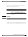
Cisco Catalyst Blade Switch 3130 for Dell Show Platform Commands
show platform acl
C-2
show platform backup interface
show platform configuration
show platform dl
C-1
C-3
C-4
C-5
show platform etherchannel
show platform forward
C-6
C-7
show platform frontend-controller
show platform ip igmp snooping
show platform ip multicast
C-9
C-10
C-11
Cisco Catalyst Blade Switch 3130 and 3032 for Dell Command Reference
xviii
OL-13271-06
Contents
show platform ip unicast
C-12
show platform ip unicast vrf compaction
show platform ip unicast vrf tcam-label
show platform ip wccp
C-17
show platform ipv6 unicast
show platform layer4op
C-18
C-20
show platform mac-address-table
show platform messaging
show platform monitor
C-23
C-24
C-25
show platform port-asic
C-26
show platform port-security
C-31
C-32
show platform resource-manager
show platform snmp counters
show platform spanning-tree
show platform tcam
show platform vlan
APPENDIX
D
C-35
C-37
show platform stack manager
show platform stack ports
C-33
C-36
show platform stp-instance
show platform tb
C-21
C-22
show platform mvr table
show platform qos
C-15
C-16
show platform ipc trace
show platform pm
C-14
C-38
C-40
C-42
C-44
C-47
Acknowledgments for Open-Source Software
D-1
INDEX
Cisco Catalyst Blade Switch 3130 and 3032 for Dell Command Reference
OL-13271-06
xix
Contents
Cisco Catalyst Blade Switch 3130 and 3032 for Dell Command Reference
xx
OL-13271-06
Preface
Audience
This guide is for the networking professional using the Cisco IOS command-line interface (CLI) to
manage the standalone Cisco Catalyst Blade Switch 3130 for Dell or blade switch stack, referred to as
the switch. Before using this guide, you should have experience working with the Cisco IOS commands
and the switch software features. Before using this guide, you should have experience working with the
concepts and terminology of Ethernet and local area networking.
You install the switch in the Dell M1000e blade server chassis, referred to as the enclosure.
Purpose
This guide provides the information that you need about the Layer 2 and Layer 3 commands that have
been created or changed for use with the switches. For information about the standard Cisco IOS
Release 12.2 commands, see the Cisco IOS documentation set available from the Cisco.com home page by
selecting Technical Support & Documentation > Cisco IOS Software.
This guide does not provide procedures for configuring your switch. For detailed configuration
procedures, see the software configuration guide for this release.
This guide does not describe system messages you might encounter. For more information, see the
system message guide for this release.
For documentation updates, see the release notes for this release.
Conventions
This publication uses these conventions to convey instructions and information:
Command descriptions use these conventions:
•
Commands and keywords are in boldface text.
•
Arguments for which you supply values are in italic.
•
Square brackets ([ ]) means optional elements.
•
Braces ({}) group required choices, and vertical bars ( | ) separate the alternative elements.
•
Braces and vertical bars within square brackets ([{ | }]) mean a required choice within an optional
element.
Cisco Catalyst Blade Switch 3130 and 3032 for Dell Command Reference
OL-13271-06
xxi
Preface
Interactive examples use these conventions:
•
Terminal sessions and system displays are in screen font.
•
Information you enter is in boldface
•
Nonprinting characters, such as passwords or tabs, are in angle brackets (< >).
screen
font.
Notes, cautions, and warnings use these conventions and symbols:
Note
Caution
Means reader take note. Notes contain helpful suggestions or references to materials not contained in
this manual.
Means reader be careful. In this situation, you might do something that could result in equipment
damage or loss of data.
Related Publications
These documents provide complete information about the switch and are available from this Cisco.com
site:
http://www.cisco.com/en/US/products/ps8742/tsd_products_support_series_home.html
Note
Before installing, configuring, or upgrading the switch, see these documents:
•
For initial configuration information, see the “Configuring the Switch Module” section in the
getting started guide or the “Configuring the Switch with the CLI-Based Setup Program” appendix
in the hardware installation guide.
•
For device manager requirements, see the “System Requirements” section in the release notes.
•
For Network Assistant requirements, see the Getting Started with Cisco Network Assistant.
•
For upgrade information, see the “Downloading Software” section in the release notes.
•
Release Notes for the Cisco Catalyst Blade Switch 3130 for Dell
•
Cisco Catalyst Blade Switch 3130 for Dell Software Configuration Guide
•
Cisco Catalyst Blade Switch 3130 for Dell Command Reference
•
Cisco Catalyst Blade Switch 3130 for Dell System Message Guide (not orderable but available on
Cisco.com)
•
Cisco Software Activation Document for Dell
•
Device manager online help (available on the switch)
•
Cisco Catalyst Blade Switch 3130 for Dell and Cisco Catalyst Blade Switch 3032 for Dell Hardware
Installation Guide
•
Cisco Catalyst Blade Switch 3130 for Dell and Cisco Catalyst Blade Switch 3032 for Dell Getting
Started Guide
•
Regulatory Compliance and Safety Information for the Cisco Catalyst Blade Switch 3000 Series for
Dell
Cisco Catalyst Blade Switch 3130 and 3032 for Dell Command Reference
xxii
OL-13271-06
Preface
•
Device manager online help (available on the switch)
•
Getting Started with Cisco Network Assistant
•
Release Notes for Cisco Network Assistant
•
Installation Note for the Cisco TwinGig Converter Module
•
Cisco Small Form-Factor Pluggable Modules Installation Notes
•
These compatibility matrix documents are available from this Cisco.com site:
http://www.cisco.com/en/US/products/hw/modules/ps5455/products_device_support_tables_list.
html
– Cisco Gigabit Ethernet Transceiver Modules Compatibility Matrix
– Cisco 100-Megabit Ethernet SFP Modules Compatibility Matrix
– Cisco Small Form-Factor Pluggable Modules Compatibility Matrix
– Compatibility Matrix for 1000BASE-T Small Form-Factor Pluggable Modules
•
For information about the Network Admission Control (NAC) features, see the Network Admission
Control Software Configuration Guide
Obtaining Documentation and Submitting a Service Request
For information on obtaining documentation, submitting a service request, and gathering additional
information, see the monthly What’s New in Cisco Product Documentation, which also lists all new and
revised Cisco technical documentation, at:
http://www.cisco.com/en/US/docs/general/whatsnew/whatsnew.html
Subscribe to the What’s New in Cisco Product Documentation as a Really Simple Syndication (RSS) feed
and set content to be delivered directly to your desktop using a reader application. The RSS feeds are a free
service and Cisco currently supports RSS version 2.0.
Cisco Catalyst Blade Switch 3130 and 3032 for Dell Command Reference
OL-13271-06
xxiii
Preface
Cisco Catalyst Blade Switch 3130 and 3032 for Dell Command Reference
xxiv
OL-13271-06
CH A P T E R
1
Using the Command-Line Interface
The switches are supported by Cisco IOS software. This chapter describes how to use the switch
command-line interface (CLI) to configure software features.
For a complete description of the commands that support these features, see Chapter 2, “Cisco Catalyst
Blade Switch 3130 for Dell Cisco IOS Commands.” For information on the boot loader commands, see
Appendix A, “Cisco Catalyst Blade Switch 3130 for Dell Boot Loader Commands.” For information on
the debug commands, see Appendix B, “Cisco Catalyst Blade Switch 3130 for Dell Debug Commands.”
For information on the show platform commands, see Appendix C, “Cisco Catalyst Blade Switch 3130
for Dell Show Platform Commands.” For more information on Cisco IOS Release 12.2, see the Cisco
IOS Release 12.2 Command Summary.
For task-oriented configuration steps, see the software configuration guide for this release.
In this document, IP refers to IP version 4 (IPv4) unless there is a specific reference to IP version 6
(IPv6).
Accessing the Switch
You manage the switch stack and the stack member interfaces through the stack master (such as a
stacking-capable switch). You cannot manage stack members on an individual switch basis. You can
connect to the stack master through the console port of one or more stack members. You can also connect
to the stack master through the chassis management controller (CMC) to the internal Ethernet
management port. Be careful with using multiple CLI sessions to the stack master. Commands you enter
in one session are not displayed in the other sessions. Therefore, it is possible to lose track of the session
from which you entered commands.
Note
We recommend using one CLI session when managing the switch stack.
If you want to configure a specific stack member port, you must include the stack member number in
the CLI command interface notation. For more information about interface notations, see the
“Configuring Interfaces” chapter in the software configuration guide for this release.
To debug a specific stack member, you can access it from the stack master by using the session
stack-member-number privileged EXEC command. The stack member number is appended to the system
prompt. For example, Switch-2# is the prompt in privileged EXEC mode for stack member 2, and the
system prompt for the stack master is Switch. Only the show and debug commands are available in a
CLI session to a specific stack member.
Cisco Catalyst Blade Switch 3130 and 3032 for Dell Command Reference
OL-13271-06
1-1
Chapter 1
Using the Command-Line Interface
CLI Command Modes
CLI Command Modes
This section describes the CLI command mode structure. Command modes support specific Cisco IOS
commands. For example, the interface interface-id command only works when entered in global
configuration mode.
These are the main command modes for the switch:
•
User EXEC
•
Privileged EXEC
•
Global configuration
•
Interface configuration
•
VLAN configuration
•
Line configuration
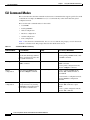
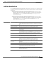
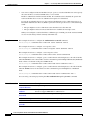
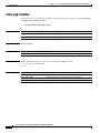
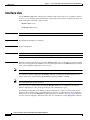
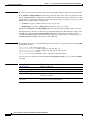
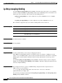
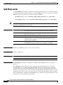
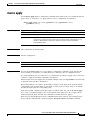
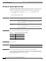
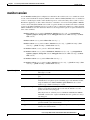
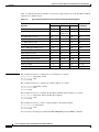
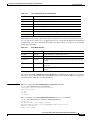
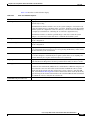
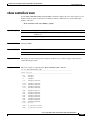
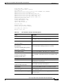
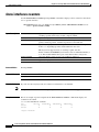
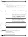
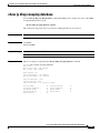
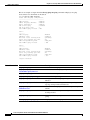
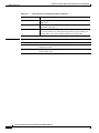
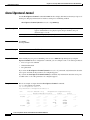
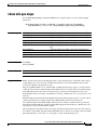
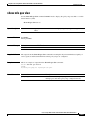
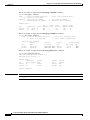
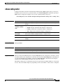
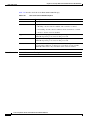
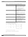
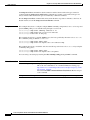
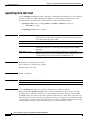
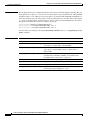
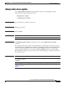
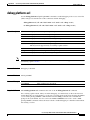
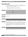
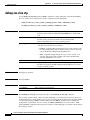
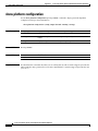
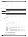
Table 1-1 lists the main command modes, how to access each mode, the prompt you see in that mode,
and how to exit that mode. The prompts listed use the default name Switch.
Table 1-1
Command Modes Summary
Command Mode
Access Method
Prompt
Exit or Access Next Mode
User EXEC
This is the first level of access.
Switch>
Enter the logout command.
To enter privileged EXEC mode, enter
the enable command.
(For the switch) Change terminal
settings, perform basic tasks, and
list system information.
Privileged EXEC
From user EXEC mode, enter the
enable command.
Switch#
To exit to user EXEC mode, enter the
disable command.
To enter global configuration mode,
enter the configure command.
Global
configuration
From privileged EXEC mode,
enter the configure command.
Switch(config)#
To exit to privileged EXEC mode,
enter the exit or end command, or
press Ctrl-Z.
To enter interface configuration mode,
enter the interface configuration
command.
Interface
configuration
From global configuration mode,
specify an interface by entering
the interface command followed
by an interface identification.
Switch(config-if)#
To exit to privileged EXEC mode,
enter the end command, or press
Ctrl-Z.
To exit to global configuration mode,
enter the exit command.
Cisco Catalyst Blade Switch 3130 and 3032 for Dell Command Reference
1-2
OL-13271-06
Chapter 1
Using the Command-Line Interface
CLI Command Modes
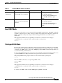
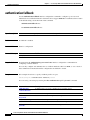
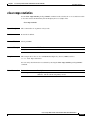
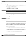
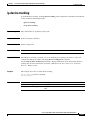
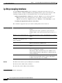
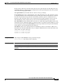
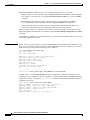
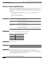
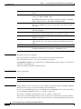
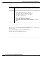
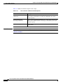
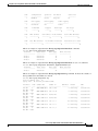
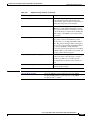
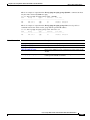
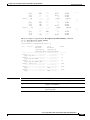
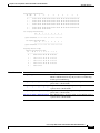
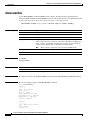
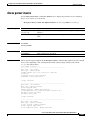
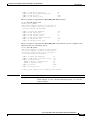
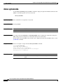
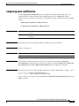
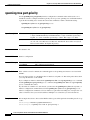
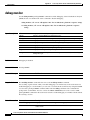
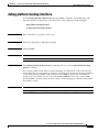
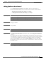
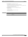
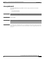
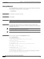
Table 1-1
Command Modes Summary (continued)
Command Mode
Access Method
Prompt
Exit or Access Next Mode
VLAN
configuration
In global configuration mode,
enter the vlan vlan-id command.
Switch(config-vlan)#
To exit to global configuration mode,
enter the exit command.
To return to privileged EXEC mode,
enter the end command, or press
Ctrl-Z.
Line configuration
From global configuration mode,
specify a line by entering the line
command.
Switch(config-line)#
To exit to global configuration mode,
enter the exit command.
To return to privileged EXEC mode,
enter the end command, or press
Ctrl-Z.
User EXEC Mode
After you access the device, you are automatically in user EXEC command mode. The EXEC commands
available at the user level are a subset of those available at the privileged level. In general, use the user
EXEC commands to temporarily change terminal settings, perform basic tests, and list system
information.
The supported commands can vary depending on the version of software in use. To display a
comprehensive list of commands, enter a question mark (?) at the prompt.
Switch> ?
Privileged EXEC Mode
Because many of the privileged commands configure operating parameters, privileged access should be
password-protected to prevent unauthorized use. The privileged command set includes those commands
contained in user EXEC mode, as well as the configure privileged EXEC command through which you
access the remaining command modes.
If your system administrator has set a password, you are prompted to enter it before being granted access
to privileged EXEC mode. The password does not appear on the screen and is case sensitive.
The privileged EXEC mode prompt is the device name followed by the pound sign ( #).
Switch#
Enter the enable command to access privileged EXEC mode:
Switch> enable
Switch#
The supported commands can vary depending on the version of software in use. To display a
comprehensive list of commands, enter a question mark (?) at the prompt.
Switch# ?
To return to user EXEC mode, enter the disable privileged EXEC command.
Cisco Catalyst Blade Switch 3130 and 3032 for Dell Command Reference
OL-13271-06
1-3
Chapter 1
Using the Command-Line Interface
CLI Command Modes
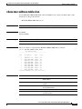
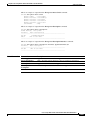
Global Configuration Mode
Global configuration commands apply to features that affect the device as a whole. Use the configure
privileged EXEC command to enter global configuration mode. The default is to enter commands from
the management console.
When you enter the configure command, a message prompts you for the source of the configuration
commands:
Switch# configure
Configuring from terminal, memory, or network [terminal]?
You can specify either the terminal or NVRAM as the source of configuration commands.
This example shows you how to access global configuration mode:
Switch# configure terminal
Enter configuration commands, one per line.
End with CNTL/Z.
The supported commands can vary depending on the version of software in use. To display a
comprehensive list of commands, enter a question mark (?) at the prompt.
Switch(config)# ?
To exit global configuration command mode and to return to privileged EXEC mode, enter the end or
exit command, or press Ctrl-Z.
Interface Configuration Mode
Interface configuration commands modify the operation of the interface. Interface configuration
commands always follow a global configuration command, which defines the interface type.
Use the interface interface-id command to access interface configuration mode. The new prompt means
interface configuration mode.
Switch(config-if)#
The supported commands can vary depending on the version of software in use. To display a
comprehensive list of commands, enter a question mark (?) at the prompt.
Switch(config-if)# ?
To exit interface configuration mode and to return to global configuration mode, enter the exit
command. To exit interface configuration mode and to return to privileged EXEC mode, enter the end
command, or press Ctrl-Z.
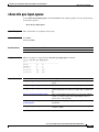
VLAN Configuration Mode
Use this mode to configure normal-range VLANs (VLAN IDs 1 to 1005) or, when VTP mode is
transparent, to configure extended-range VLANs (VLAN IDs 1006 to 4094). When VTP mode is
transparent, the VLAN and VTP configuration is saved in the running configuration file, and you can
save it to the switch startup configuration file by using the copy running-config startup-config
privileged EXEC command. The configurations of VLAN IDs 1 to 1005 are saved in the VLAN database
if VTP is in transparent or server mode. The extended-range VLAN configurations are not saved in the
VLAN database.
Cisco Catalyst Blade Switch 3130 and 3032 for Dell Command Reference
1-4
OL-13271-06
Chapter 1
Using the Command-Line Interface
CLI Command Modes
Enter the vlan vlan-id global configuration command to access config-vlan mode:
Switch(config)# vlan 2000
Switch(config-vlan)#
The supported keywords can vary but are similar to the commands available in VLAN configuration
mode. To display a comprehensive list of commands, enter a question mark (?) at the prompt.
Switch(config-vlan)# ?
For extended-range VLANs, all characteristics except the MTU size must remain at the default setting.
To return to global configuration mode, enter exit; to return to privileged EXEC mode, enter end. All
the commands except shutdown take effect when you exit config-vlan mode.
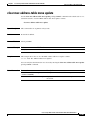
Line Configuration Mode
Line configuration commands modify the operation of a terminal line. Line configuration commands
always follow a line command, which defines a line number. Use these commands to change terminal
parameter settings line-by-line or for a range of lines.
Use the line vty line_number [ending_line_number] command to enter line configuration mode. The
new prompt means line configuration mode. The following example shows how to enter line
configuration mode for virtual terminal line 7:
Switch(config)# line vty 0 7
The supported commands can vary depending on the version of software in use. To display a
comprehensive list of commands, enter a question mark (?) at the prompt.
Switch(config-line)# ?
To exit line configuration mode and to return to global configuration mode, use the exit command. To
exit line configuration mode and to return to privileged EXEC mode, enter the end command, or press
Ctrl-Z.
Cisco Catalyst Blade Switch 3130 and 3032 for Dell Command Reference
OL-13271-06
1-5
Chapter 1
Using the Command-Line Interface
CLI Command Modes
Cisco Catalyst Blade Switch 3130 and 3032 for Dell Command Reference
1-6
OL-13271-06
CH A P T E R
2
Cisco Catalyst Blade Switch 3130 for Dell Cisco
IOS Commands
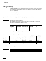
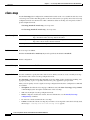
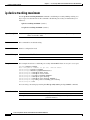
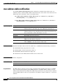
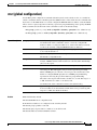
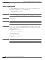
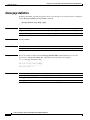
aaa accounting dot1x
Use the aaa accounting dot1x global configuration command to enable authentication, authorization,
and accounting (AAA) accounting and to create method lists defining specific accounting methods on a
per-line or per-interface basis for IEEE 802.1x sessions. Use the no form of this command to disable
IEEE 802.1x accounting.
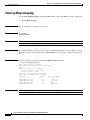
aaa accounting dot1x {name | default} start-stop {broadcast group {name | radius | tacacs+}
[group {name | radius | tacacs+} ... ] | group {name | radius | tacacs+} [group {name | radius
| tacacs+} ... ]}
no aaa accounting dot1x {name | default}
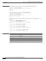
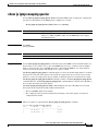
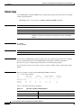
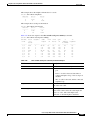
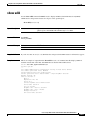
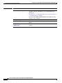
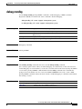
Syntax Description
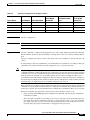
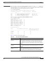
name
Name of a server group. This is optional when you enter it after the
broadcast group and group keywords.
default
Use the accounting methods that follow as the default list for accounting
services.
start-stop
Send a start accounting notice at the beginning of a process and a stop
accounting notice at the end of a process. The start accounting record is sent
in the background. The requested-user process begins regardless of whether
or not the start accounting notice was received by the accounting server.
broadcast
Enable accounting records to be sent to multiple AAA servers and send
accounting records to the first server in each group. If the first server is
unavailable, the switch uses the list of backup servers to identify the first
server.
group
Specify the server group to be used for accounting services. These are valid
server group names:
•
name—Name of a server group.
•
radius—List of all RADIUS hosts.
•
tacacs+—List of all TACACS+ hosts.
The group keyword is optional when you enter it after the broadcast group
and group keywords. You can enter more than optional group keyword.
Cisco Catalyst Blade Switch 3130 and 3032 for Dell Command Reference
OL-13271-06
2-1
Chapter 2
Cisco Catalyst Blade Switch 3130 for Dell Cisco IOS Commands
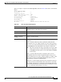
aaa accounting dot1x
radius
(Optional) Enable RADIUS authorization.
tacacs+
(Optional) Enable TACACS+ accounting.
Defaults
AAA accounting is disabled.
Command Modes
Global configuration
Command History
Release
Modification
12.2(40)EX1
This command was introduced.
Usage Guidelines
This command requires access to a RADIUS server.
We recommend that you enter the dot1x reauthentication interface configuration command before
configuring IEEE 802.1x RADIUS accounting on an interface.
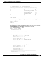
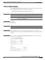
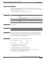
Examples
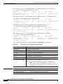
This example shows how to configure IEEE 802.1x accounting:
Switch(config)# aaa new-model
Switch(config)# aaa accounting dot1x default start-stop group radius
Note
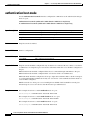
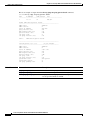
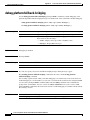
Related Commands
The RADIUS authentication server must be properly configured to accept and log update or watchdog
packets from the AAA client.
Command
Description
aaa authentication
dot1x
Specifies one or more AAA methods for use on interfaces running
IEEE 802.1x.
aaa new-model
Enables the AAA access control model. For syntax information, see the
Cisco IOS Security Command Reference, Release 12.2 > Authentication,
Authorization, and Accounting > Authentication Commands.
dot1x reauthentication
Enables or disables periodic reauthentication.
dot1x timeout
reauth-period
Sets the number of seconds between re-authentication attempts.
Cisco Catalyst Blade Switch 3130 and 3032 for Dell Command Reference
2-2
OL-13271-06
Chapter 2
Cisco Catalyst Blade Switch 3130 for Dell Cisco IOS Commands
aaa authentication dot1x
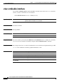
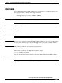
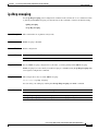
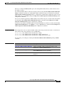
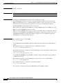
aaa authentication dot1x
Use the aaa authentication dot1x global configuration command on the switch stack or on a standalone
switch to specify the authentication, authorization, and accounting (AAA) method to use on ports
complying with the IEEE 802.1x authentication. Use the no form of this command to disable
authentication.
aaa authentication dot1x {default} method1
no aaa authentication dot1x {default}
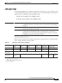
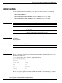
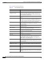
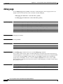
Syntax Description
Note
default
Use the listed authentication method that follows this argument as the default
method when a user logs in.
method1
Enter the group radius keywords to use the list of all RADIUS servers for
authentication.
Though other keywords are visible in the command-line help strings, only the default and group radius
keywords are supported.
Defaults
No authentication is performed.
Command Modes
Global configuration
Command History
Release
Modification
12.2(40)EX1
This command was introduced.
Usage Guidelines
The method argument identifies the method that the authentication algorithm tries in the given sequence
to validate the password provided by the client. The only method that is truly IEEE 802.1x-compliant is
the group radius method, in which the client data is validated against a RADIUS authentication server.
If you specify group radius, you must configure the RADIUS server by entering the radius-server host
global configuration command.
Use the show running-config privileged EXEC command to display the configured lists of
authentication methods.
Examples
This example shows how to enable AAA and how to create an IEEE 802.1x-compliant authentication
list. This authentication first tries to contact a RADIUS server. If this action returns an error, the user is
not allowed access to the network.
Switch(config)# aaa new-model
Switch(config)# aaa authentication dot1x default group radius
Cisco Catalyst Blade Switch 3130 and 3032 for Dell Command Reference
OL-13271-06
2-3
Chapter 2
Cisco Catalyst Blade Switch 3130 for Dell Cisco IOS Commands
aaa authentication dot1x
You can verify your settings by entering the show running-config privileged EXEC command.
Related Commands
Command
Description
aaa new-model
Enables the AAA access control model. For syntax information, see the
Cisco IOS Security Command Reference, Release 12.2 > Authentication,
Authorization, and Accounting > Authentication Commands.
show running-config
Displays the operating configuration. For syntax information, use this link to
the Cisco IOS Release 12.2 Command Reference listing page:
http://www.cisco.com/en/US/products/sw/iosswrel/ps1835/prod_command
_reference_list.html
Select the Cisco IOS Commands Master List, Release 12.2 to navigate to
the command.
Cisco Catalyst Blade Switch 3130 and 3032 for Dell Command Reference
2-4
OL-13271-06
Chapter 2
Cisco Catalyst Blade Switch 3130 for Dell Cisco IOS Commands
aaa authorization network
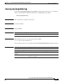
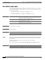
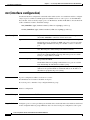
aaa authorization network
Use the aaa authorization network global configuration command on the switch stack or on a
standalone switch to the configure the switch to use user-RADIUS authorization for all network-related
service requests, such as IEEE 802.1x per-user access control lists (ACLs) or VLAN assignment. Use
the no form of this command to disable RADIUS user authorization.
aaa authorization network default group radius
no aaa authorization network default
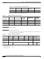
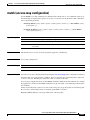
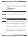
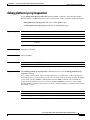
Syntax Description
default group
radius
Defaults
Authorization is disabled.
Command Modes
Global configuration
Command History
Release
Modification
12.2(40)EX1
This command was introduced.
Usage Guidelines
Use the list of all RADIUS hosts in the server group as the default authorization
list.
Use the aaa authorization network default group radius global configuration command to allow the
switch to download IEEE 802.1x authorization parameters from the RADIUS servers in the default
authorization list. The authorization parameters are used by features such as per-user ACLs or VLAN
assignment to get parameters from the RADIUS servers.
Use the show running-config privileged EXEC command to display the configured lists of authorization
methods.
Examples
This example shows how to configure the switch for user RADIUS authorization for all network-related
service requests:
Switch(config)# aaa authorization network default group radius
You can verify your settings by entering the show running-config privileged EXEC command.
Related Commands
Command
Description
show running-config
Displays the operating configuration. For syntax information, use this link to
the Cisco IOS Release 12.2 Command Reference listing page:
http://www.cisco.com/en/US/products/sw/iosswrel/ps1835/prod_command
_reference_list.html
Select the Cisco IOS Commands Master List, Release 12.2 to navigate to
the command.
Cisco Catalyst Blade Switch 3130 and 3032 for Dell Command Reference
OL-13271-06
2-5
Chapter 2
Cisco Catalyst Blade Switch 3130 for Dell Cisco IOS Commands
action
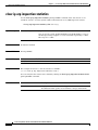
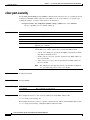
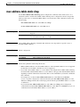
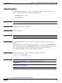
action
Use the action access-map configuration command on the switch stack or on a standalone switch to set
the action for the VLAN access map entry. Use the no form of this command to return to the default
setting.
action {drop | forward}
no action
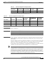
Syntax Description
drop
Drop the packet when the specified conditions are matched.
forward
Forward the packet when the specified conditions are matched.
Defaults
The default action is to forward packets.
Command Modes
Access-map configuration
Command History
Release
Modification
12.2(40)EX1
This command was introduced.
Usage Guidelines
You enter access-map configuration mode by using the vlan access-map global configuration command.
If the action is drop, you should define the access map, including configuring any access control list
(ACL) names in match clauses, before applying the map to a VLAN, or all packets could be dropped.
In access-map configuration mode, use the match access-map configuration command to define the
match conditions for a VLAN map. Use the action command to set the action that occurs when a packet
matches the conditions.
The drop and forward parameters are not used in the no form of the command.
Examples
This example shows how to identify and apply a VLAN access map vmap4 to VLANs 5 and 6 that causes
the VLAN to forward an IP packet if the packet matches the conditions defined in access list al2:
Switch(config)# vlan access-map vmap4
Switch(config-access-map)# match ip address al2
Switch(config-access-map)# action forward
Switch(config-access-map)# exit
Switch(config)# vlan filter vmap4 vlan-list 5-6
You can verify your settings by entering the show vlan access-map privileged EXEC command.
Cisco Catalyst Blade Switch 3130 and 3032 for Dell Command Reference
2-6
OL-13271-06
Chapter 2
Cisco Catalyst Blade Switch 3130 for Dell Cisco IOS Commands
action
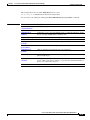
Related Commands
Command
Description
access-list {deny | permit}
Configures a standard numbered ACL. For syntax information, select
Cisco IOS IP Command Reference, Volume 1 of 3:Addressing
and Services, Release 12.2 > IP Services Commands.
ip access-list
Creates a named access list. For syntax information, select Cisco
IOS IP Command Reference, Volume 1 of 3:Addressing and
Services, Release 12.2 > IP Services Commands.
mac access-list extended
Creates a named MAC address access list.
match (class-map
configuration)
Defines the match conditions for a VLAN map.
show vlan access-map
Displays the VLAN access maps created on the switch.
vlan access-map
Creates a VLAN access map.
Cisco Catalyst Blade Switch 3130 and 3032 for Dell Command Reference
OL-13271-06
2-7
Chapter 2
Cisco Catalyst Blade Switch 3130 for Dell Cisco IOS Commands
archive copy-sw
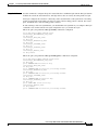
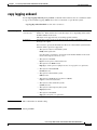
archive copy-sw
Use the archive copy-sw privileged EXEC command on the stack master to copy the running image from
the flash memory on one stack member to the flash memory on one or more other stack members.
archive copy-sw [/destination-system destination-stack-member-number] [/force-reload]
[leave-old-sw] [/no-set-boot] [/overwrite] [/reload] [/safe] source-stack-member-number
Note
Syntax Description
This command is supported only on stacking-capable switches.
/destination-system
destination-stackmember-number
(Optional) The number of the stack member to which to copy the running
image. The range is 1 to 9.
/force-reload
(Optional) Unconditionally force a system reload after successfully
downloading the software image.
/leave-old-sw
(Optional) Keep the old software version after a successful download.
/no-set-boot
(Optional) Do not alter the setting of the BOOT environment variable to
point to the new software image after it is successfully downloaded.
/overwrite
(Optional) Overwrite the software image in flash memory with the
downloaded one.
/reload
(Optional) Reload the system after downloading the image unless the
configuration has been changed and not been saved.
/safe
(Optional) Keep the current software image; do not delete it to make room
for the new software image before the new image is downloaded. The current
image is deleted after the download.
source-stack-membernumber
The number of the stack member from which to copy the running image. The
range is 1 to 9.
Command Modes
Privileged EXEC
Command History
Release
Modification
12.2(40)EX1
This command was introduced.
Usage Guidelines
The current software image is not overwritten with the copied image.
Both the software image and HTML files are copied.
The new image is copied to the flash: file system.
The BOOT environment variable is changed to point to the new software image on the flash: file system.
Image names are case sensitive; the image file is provided in tar format.
Cisco Catalyst Blade Switch 3130 and 3032 for Dell Command Reference
2-8
OL-13271-06
Chapter 2
Cisco Catalyst Blade Switch 3130 for Dell Cisco IOS Commands
archive copy-sw
Note
To successfully use the archive copy-sw privileged EXEC command, you must have downloaded from
a TFTP server the images for both the stack member switch being added and the stack master. You use
the archive download-sw privileged EXEC command to perform the download.
At least one stack member must be running the image that is to be copied to the switch that has
incompatible software.
You can copy the image to more than one specific stack member by repeating the /destination-system
destination-stack-member-number option in the command for each stack member to be upgraded. If you
do not specify the destination-stack-member-number, the default is to copy the running image file to all
stack members.
Using the /safe or /leave-old-sw option can cause the new copied image to fail if there is insufficient
flash memory. If leaving the software in place would prevent the new image from fitting in flash memory
due to space constraints, an error results.
If you used the /leave-old-sw option and did not overwrite the old image when you copied the new one,
you can remove the old image by using the delete privileged EXEC command. For more information,
see the “delete” section on page 2-119.
Use the /overwrite option to overwrite the image on the flash device with the copied one.
If you specify the command without the /overwrite option, the algorithm verifies that the new image is
not the same as the one on the switch flash device or is not running on any stack members. If the images
are the same, the copy does not occur. If the images are different, the old image is deleted, and the new
one is copied.
After copying a new image, enter the reload privileged EXEC command to begin using the new image,
or specify the /reload or /force-reload option in the archive copy-sw command.
You can enter one or more of these options with the source-stack-member-number option:
•
/destination-system destination-stack-member-number
•
/force-reload
•
/leave-old-sw
•
/no-set-boot
•
/overwrite
•
/reload
•
/safe
If you enter the source-stack-member-number option before one of the previous options, you can enter
only the archive copy-sw source-stack-member-number command.
These are examples of how you can enter the archive copy-sw command:
•
To copy the running image from a stack member to another stack member and to overwrite the
software image in the second stack member’s flash memory (if it already exists) with the copied one,
enter the archive copy-sw /destination destination-stack-member-number /overwrite
source-stack-member-number command.
•
To copy the running image from a stack member to another stack member, keep the current software
image, and reload the system after the image copies, enter the archive copy-sw /destination
destination-stack-member-number /safe /reload source-stack-member-number command.
Cisco Catalyst Blade Switch 3130 and 3032 for Dell Command Reference
OL-13271-06
2-9
Chapter 2
Cisco Catalyst Blade Switch 3130 for Dell Cisco IOS Commands
archive copy-sw
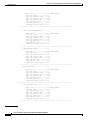
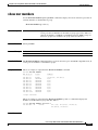
Examples
This example shows how to copy the running image from stack member 6 to stack member 8:
Switch# archive copy-sw /destination-system 8 6
This example shows how to copy the running image from stack member 6 to all the other stack members:
Switch# archive copy-sw 6
This example shows how to copy the running image from stack member 5 to stack member 7. If the
image being copied already exists on the second stack member’s flash memory, it can be overwritten
with the copied one. The system reloads after the image is copied:
Switch# archive copy-sw /destination-system 7 /overwrite /force-reload 5
Related Commands
Command
Description
archive download-sw
Downloads a new image from a TFTP server to the switch.
archive tar
Creates a tar file, lists the files in a tar file, or extracts the files from a tar file.
archive upload-sw
Uploads an existing image on the switch to a server.
delete
Deletes a file or directory on the flash memory device.
Cisco Catalyst Blade Switch 3130 and 3032 for Dell Command Reference
2-10
OL-13271-06
Chapter 2
Cisco Catalyst Blade Switch 3130 for Dell Cisco IOS Commands
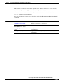
archive download-sw
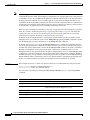
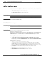
archive download-sw
Use the archive download-sw privileged EXEC command on the switch stack or on a standalone switch
to download a new image from a TFTP server to the switch or switch stack and to overwrite or keep the
existing image.
archive download-sw [/allow-feature-upgrade | /destination-system stack-member-number |
/directory | /force-reload | /imageonly | /leave-old-sw | /no-set-boot | /no-version-check |
/only-system-type system-type | /overwrite | /reload | /safe] source-url1 [source-url2
source-url3 source-url4]
archive download-sw [/allow-feature-upgrade | /destination-system stack-member-number |
/directory | /force-reload | /imageonly | /leave-old-sw | /no-set-boot | /no-version-check |
/only-system-type system-type | /overwrite | /reload | /safe] /directory source-url1
[source-url2 source-url3 source-url4]
Syntax Description
/allow-feature-upgrade
Allow installation of software images with different feature sets (for
example, upgrade from the IP base feature set to the IP services features
set).
/destination-system
stack-member-number
Specify the specific stack member to be upgraded. The range is 1 to 9.
/directory
Specify a directory for all of the images.
/force-reload
Unconditionally force a system reload after successfully downloading the
software image.
/imageonly
Download only the software image but not the HTML files associated with
the embedded device manager. The HTML files for the existing version are
deleted only if the existing version is being overwritten or removed.
/leave-old-sw
Keep the old software version after a successful download.
/no-set-boot
Do not alter the setting of the BOOT environment variable to point to the
new software image after it is successfully downloaded.
/no-version-check
Download the software image without checking the compatibility of the
stack protocol version on the image and on the switch stack.
This keyword is supported only on stacking-capable switches.
This keyword is supported only on stacking-capable switches.
/only-system-type
system-type
Specify the specific system type to be upgraded. The range is 0 to
FFFFFFFF.
This keyword is supported only on stacking-capable switches.
/overwrite
Overwrite the software image in flash memory with the downloaded one.
/reload
Reload the system after successfully downloading the image unless the
configuration has been changed and not been saved.
/safe
Keep the current software image; do not delete it to make room for the new
software image before the new image is downloaded. The current image is
deleted after the download.
Cisco Catalyst Blade Switch 3130 and 3032 for Dell Command Reference
OL-13271-06
2-11
Chapter 2
Cisco Catalyst Blade Switch 3130 for Dell Cisco IOS Commands
archive download-sw
source-url1 [sourceurl2
sourceurl3 sourceurl4]
The source URLs for the software images.
On a standalone switch, enter one source URL for the software image that
the switch supports.
In a switch stack, you can enter source URLs for the software images that
the stack members support as follows:
•
Up to two source URLs without the /directory keyword.
•
Up to four source URLS with the /directory keyword.
The image-name.tar is the software image to download and install on the
switch.
These options are supported:
•
Local flash file system syntax on the standalone switch or the stack
master:
flash:
Local flash file system syntax on a stack member:
flash member number:
The member number can be from 1 to 9.
Defaults
•
FTP syntax:
ftp:[[//username[:password]@location]/directory]/image-name.tar
•
HTTP server syntax:
http://[[username:password]@]{hostname |
host-ip}[/directory]/image-name.tar
•
Secure HTTP server syntax:
https://[[username:password]@]{hostname |
host-ip}[/directory]/image-name.tar
•
Remote Copy Protocol (RCP) syntax:
rcp:[[//username@location]/directory]/image-name.tar
•
Secure Copy Protocol (SCP) syntax for the:
scp:[[//username@location]/directory]/image-name.tar
•
The syntax for the TFTP:
tftp:[[//location]/directory]/image-name.tar
The current software image is not overwritten with the downloaded image.
Both the software image and HTML files are downloaded.
The new image is downloaded to the flash: file system.
The BOOT environment variable is changed to point to the new software image on the flash: file system.
Image names are case sensitive; the image file is provided in tar format.
Compatibility of the stack protocol version on the image to be downloaded is checked with the version
on the switch stack.
Command Modes
Privileged EXEC
Cisco Catalyst Blade Switch 3130 and 3032 for Dell Command Reference
2-12
OL-13271-06
Chapter 2
Cisco Catalyst Blade Switch 3130 for Dell Cisco IOS Commands
archive download-sw
Command History
Usage Guidelines
Release
Modification
12.2(40)EX1
This command was introduced.
Use the /allow-feature-upgrade option to allow installation of an image with a different feature set, for
example, upgrading from the IP base feature set to the IP services feature.
You can use the archive download-sw /directory command to specify a directory only once, followed
by a tar file or list of tar files to be downloaded, instead of specifying complete paths with each tar file.
The /imageonly option removes the HTML files for the existing image if the existing image is being
removed or replaced. Only the Cisco IOS image (without the HTML files) is downloaded.
Using the /safe or /leave-old-sw option can cause the new image download to fail if there is insufficient
flash memory. If leaving the software in place prevents the new image from fitting in flash memory due
to space constraints, an error results.
If you used the /leave-old-sw option and did not overwrite the old image when you downloaded the new
one, you can remove the old image by using the delete privileged EXEC command. For more
information, see the “delete” section on page 2-119.
Use the /no-version-check option if you want to download an image that has a different stack protocol
version than the one existing on the switch stack. You must use this option with the /destination-system
option to specify the specific stack member to be upgraded with the image.
Note
Use the /no-version-check option with care. All stack members, including the stack master, must have
the same stack protocol version to be in the same switch stack. This option allows an image to be
downloaded without first confirming the compatibility of its stack protocol version with the version of
the switch stack.
You can upgrade more than one specific stack member by repeating the /destination-system option in
the command for each stack member to be upgraded.
Use the /overwrite option to overwrite the image on the flash device with the downloaded one.
If you specify the command without the /overwrite option, the download algorithm verifies that the new
image is not the same as the one on the switch flash device or is not running on any stack members. If
the images are the same, the download does not occur. If the images are different, the old image is
deleted, and the new one is downloaded.
After downloading a new image, enter the reload privileged EXEC command to begin using the new
image, or specify the /reload or /force-reload option in the archive download-sw command.
Use the /directory option to specify a directory for the images.
Examples
This example shows how to download a new image from a TFTP server at 172.20.129.10 and to
overwrite the image on the switch:
Switch# archive download-sw /overwrite tftp://172.20.129.10/test-image.tar
This example shows how to download only the software image from a TFTP server at 172.20.129.10 to
the switch:
Switch# archive download-sw /imageonly tftp://172.20.129.10/test-image.tar
Cisco Catalyst Blade Switch 3130 and 3032 for Dell Command Reference
OL-13271-06
2-13
Chapter 2
Cisco Catalyst Blade Switch 3130 for Dell Cisco IOS Commands
archive download-sw
This example shows how to keep the old software version after a successful download:
Switch# archive download-sw /leave-old-sw tftp://172.20.129.10/test-image.tar
This example specifies the location of two tar images without having to specify the path each time:
Switch# archive download-sw tftp://10.1.1.10/
cbs31x0-universal-tar.122-40.EX2.tar cbs31x0-universal-tar.122-40.EX1.tar
This example shows how to upgrade stack members 6 and 8:
Switch# archive download-sw /imageonly /destination-system 6 /destination-system 8
tftp://172.20.129.10/test-image.tar
Related Commands
Command
Description
archive copy-sw
Copies the running image from the flash memory on one stack member to the
flash memory on one or more other stack members.
archive tar
Creates a tar file, lists the files in a tar file, or extracts the files from a tar file.
archive upload-sw
Uploads an existing image on the switch to a server.
delete
Deletes a file or directory on the flash memory device.
Cisco Catalyst Blade Switch 3130 and 3032 for Dell Command Reference
2-14
OL-13271-06
Chapter 2
Cisco Catalyst Blade Switch 3130 for Dell Cisco IOS Commands
archive tar
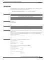
archive tar
Use the archive tar privileged EXEC command on the switch stack or on a standalone switch to create
a tar file, list files in a tar file, or extract the files from a tar file.
archive tar {/create destination-url flash:/file-url} | {/table source-url} | {/xtract source-url
flash:/file-url [dir/file...]}
Syntax Description
/create destination-url
flash:/file-url
Create a new tar file on the local or network file system.
For destination-url, specify the destination URL alias for the local or
network file system and the name of the tar file to create. These options
are supported:
•
The syntax for the local flash filesystem:
flash:
•
The syntax for the FTP:
ftp:[[//username[:password]@location]/directory]/tar-filename.tar
•
The syntax for an HTTP server:
http://[[username:password]@]{hostname |
host-ip}[/directory]/image-name.tar
•
The syntax for a secure HTTP server:
https://[[username:password]@]{hostname |
host-ip}[/directory]/image-name.tar
•
The syntax for the Remote Copy Protocol (RCP):
rcp:[[//username@location]/directory]/tar-filename.tar
•
The syntax for the TFTP:
tftp:[[//location]/directory]/tar-filename.tar
The tar-filename.tar is the tar file to be created.
For flash:/file-url, specify the location on the local flash file system from
which the new tar file is created.
An optional list of files or directories within the source directory can be
specified to write to the new tar file. If none are specified, all files and
directories at this level are written to the newly created tar file.
Cisco Catalyst Blade Switch 3130 and 3032 for Dell Command Reference
OL-13271-06
2-15
Chapter 2
Cisco Catalyst Blade Switch 3130 for Dell Cisco IOS Commands
archive tar
/table source-url
Display the contents of an existing tar file to the screen.
For source-url, specify the source URL alias for the local or network file
system. These options are supported:
•
The syntax for the local flash file system:
flash:
•
The syntax for the FTP:
ftp:[[//username[:password]@location]/directory]/tar-filename.tar
•
The syntax for an HTTP server:
http://[[username:password]@]{hostname |
host-ip}[/directory]/image-name.tar
•
The syntax for a secure HTTP server:
https://[[username:password]@]{hostname |
host-ip}[/directory]/image-name.tar
•
The syntax for the RCP:
rcp:[[//username@location]/directory]/tar-filename.tar
•
The syntax for the TFTP:
tftp:[[//location]/directory]/tar-filename.tar
The tar-filename.tar is the tar file to display.
/xtract source-url
flash:/file-url [dir/file...]
Extract files from a tar file to the local file system.
For source-url, specify the source URL alias for the local file system.
These options are supported:
•
The syntax for the local flash file system:
flash:
•
The syntax for the FTP:
ftp:[[//username[:password]@location]/directory]/tar-filename.tar
•
The syntax for an HTTP server:
http://[[username:password]@]{hostname |
host-ip}[/directory]/image-name.tar
•
The syntax for a secure HTTP server:
https://[[username:password]@]{hostname |
host-ip}[/directory]/image-name.tar
•
The syntax for the RCP:
rcp:[[//username@location]/directory]/tar-filename.tar
•
The syntax for the TFTP:
tftp:[[//location]/directory]/tar-filename.tar
The tar-filename.tar is the tar file from which to extract.
For flash:/file-url [dir/file...], specify the location on the local flash file
system into which the tar file is extracted. Use the dir/file... option to
specify an optional list of files or directories within the tar file to be
extracted. If none are specified, all files and directories are extracted.
Defaults
There is no default setting.
Cisco Catalyst Blade Switch 3130 and 3032 for Dell Command Reference
2-16
OL-13271-06
Chapter 2
Cisco Catalyst Blade Switch 3130 for Dell Cisco IOS Commands
archive tar
Command Modes
Privileged EXEC
Command History
Release
Modification
12.2(40)EX1
This command was introduced.
Usage Guidelines
Filenames and directory names are case sensitive.
Image names are case sensitive.
Examples
This example shows how to create a tar file. The command writes the contents of the new-configs
directory on the local flash device to a file named saved.tar on the TFTP server at 172.20.10.30:
Switch# archive tar /create tftp:172.20.10.30/saved.tar flash:/new-configs
This example shows how to display the contents of the cbs31x0-universal-tar.12-40.EX1 file that is in
flash memory. The contents of the tar file appear on the screen:
Switch# archive tar /table flash:cbs31x0-universal-tar.-12-40.EX1.tar
info (219 bytes)
cbs31x0-universal-mz.122-40.EX1/ (directory)
cbs31x0-universal-mz.122-40.EX1 (610856 bytes)
cbs31x0-universal-mz.122-40.EX1/info (219 bytes)
info.ver (219 bytes)
This example shows how to display only the cbs31x0-universal-tar.12-40.EX1/html directory and its
contents:
Switch# archive tar /table flash:cbs31x0-universal-12-40.EX1.tar
cbs31x0-universal-12-40/html
cbs31x0-universal-mz.122-40.EX1/html/ (directory)
cbs31x0-universal-mz.122-40.EX1/html/const.htm (556 bytes)
cbs31x0-universal-mz.122-40.EX1/html/xhome.htm (9373 bytes)
cbs31x0-universal-mz.122-40.EX1/html/menu.css (1654 bytes)
<output truncated>
This example shows how to extract the contents of a tar file on the TFTP server at 172.20.10.30. This
command extracts just the new-configs directory into the root directory on the local flash file system.
The remaining files in the saved.tar file are ignored.
Switch# archive tar /xtract tftp://172.20.10.30/saved.tar flash:/ new-configs
Related Commands
Command
Description
archive copy-sw
Copies the running image from the flash memory on one stack member to the
flash memory on one or more other stack members.
archive download-sw
Downloads a new image from a TFTP server to the switch.
archive upload-sw
Uploads an existing image on the switch to a server.
Cisco Catalyst Blade Switch 3130 and 3032 for Dell Command Reference
OL-13271-06
2-17
Chapter 2
Cisco Catalyst Blade Switch 3130 for Dell Cisco IOS Commands
archive upload-sw
archive upload-sw
Use the archive upload-sw privileged EXEC command on the switch stack or on a standalone switch to
upload an existing switch image to a server.
archive upload-sw [/source-system-num stack member number | /version version_string]
destination-url
Syntax Description
/source-system-num
stack member number
Specify the specific stack member containing the image that is to be
uploaded.
This keyword is supported only on stacking-capable switches.
/version version_string
(Optional) Specify the specific version string of the image to be uploaded.
destination-url
The destination URL alias for a local or network file system. The
image-name.tar is the name of software image to be stored on the server.
These options are supported:
•
Local flash file system syntax on the standalone switch or the stack
master:
flash:
Local flash file system syntax on a stack member:
flash member number:
•
FTP syntax:
ftp:[[//username[:password]@location]/directory]/image-name.tar
•
HTTP server syntax:
http://[[username:password]@]{hostname |
host-ip}[/directory]/image-name.tar
•
Secure HTTP server syntax:
https://[[username:password]@]{hostname |
host-ip}[/directory]/image-name.tar
•
Remote Copy Protocol (RCP) syntax:
rcp:[[//username@location]/directory]/image-name.tar
•
TFTP syntax:
tftp:[[//location]/directory]/image-name.tar
Defaults
Uploads the currently running image from the flash: file system.
Command Modes
Privileged EXEC
Command History
Release
Modification
12.2(40)EX1
This command was introduced.
Cisco Catalyst Blade Switch 3130 and 3032 for Dell Command Reference
2-18
OL-13271-06
Chapter 2
Cisco Catalyst Blade Switch 3130 for Dell Cisco IOS Commands
archive upload-sw
Usage Guidelines
You must specify that the /source-system-num option uses the /version option. The options together
upload the specified image, not the running image, of a specific stack member.
Use the upload feature only if the HTML files associated with the embedded device manager have been
installed with the existing image.
The files are uploaded in this sequence: the Cisco IOS image, the HTML files, and info. After these files
are uploaded, the software creates the tar file.
Image names are case sensitive.
Examples
This example shows how to upload the currently running image on stack member 6 to a TFTP server at
172.20.140.2:
Switch# archive upload-sw /source-system-num 6 tftp://172.20.140.2/test-image.tar
Related Commands
Command
Description
archive copy-sw
Copies the running image from the flash memory on one stack member to the
flash memory on one or more other stack members.
archive download-sw
Downloads a new image to the switch.
archive tar
Creates a tar file, lists the files in a tar file, or extracts the files from a tar file.
Cisco Catalyst Blade Switch 3130 and 3032 for Dell Command Reference
OL-13271-06
2-19
Chapter 2
Cisco Catalyst Blade Switch 3130 for Dell Cisco IOS Commands
arp access-list
arp access-list
Use the arp access-list global configuration command on the switch stack or on a standalone switch to
define an Address Resolution Protocol (ARP) access control list (ACL) or to add clauses to the end of a
previously defined list. Use the no form of this command to delete the specified ARP access list.
arp access-list acl-name
no arp access-list acl-name
This command is supported only if your switch is running the IP services feature set.
Syntax Description
acl-name
Defaults
No ARP access lists are defined.
Command Modes
Global configuration
Command History
Release
Modification
12.2(40)EX1
This command was introduced.
Usage Guidelines
Name of the ACL.
After entering the arp access-list command, you enter ARP access-list configuration mode, and these
configuration commands are available:
•
default: returns a command to its default setting.
•
deny: specifies packets to reject. For more information, see the “deny (ARP access-list
configuration)” section on page 2-120.
•
exit: exits ARP access-list configuration mode.
•
no: negates a command or returns to default settings.
•
permit: specifies packets to forward. For more information, see the “permit (ARP access-list
configuration)” section on page 2-407.
Use the permit and deny access-list configuration commands to forward and to drop ARP packets based
on the specified matching criteria.
When the ARP ACL is defined, you can apply it to a VLAN by using the ip arp inspection filter vlan
global configuration command. ARP packets containing only IP-to-MAC address bindings are compared
to the ACL. All other types of packets are bridged in the ingress VLAN without validation. If the ACL
permits a packet, the switch forwards it. If the ACL denies a packet because of an explicit deny
statement, the switch drops the packet. If the ACL denies a packet because of an implicit deny statement,
the switch compares the packet to the list of DHCP bindings (unless the ACL is static, which means that
packets are not compared to the bindings).
Cisco Catalyst Blade Switch 3130 and 3032 for Dell Command Reference
2-20
OL-13271-06
Chapter 2
Cisco Catalyst Blade Switch 3130 for Dell Cisco IOS Commands
arp access-list
Examples
This example shows how to define an ARP access list and to permit both ARP requests and ARP
responses from a host with an IP address of 1.1.1.1 and a MAC address of 0000.0000.abcd:
Switch(config)# arp access-list static-hosts
Switch(config-arp-nacl)# permit ip host 1.1.1.1 mac host 00001.0000.abcd
Switch(config-arp-nacl)# end
You can verify your settings by entering the show arp access-list privileged EXEC command.
Related Commands
Command
Description
deny (ARP access-list
configuration)
Denies an ARP packet based on matches compared against the DHCP
bindings.
ip arp inspection filter Permits ARP requests and responses from a host configured with a static IP
vlan
address.
permit (ARP
access-list
configuration)
Permits an ARP packet based on matches compared against the DHCP
bindings.
show arp access-list
Displays detailed information about ARP access lists.
Cisco Catalyst Blade Switch 3130 and 3032 for Dell Command Reference
OL-13271-06
2-21
Chapter 2
Cisco Catalyst Blade Switch 3130 for Dell Cisco IOS Commands
authentication command bounce-port ignore
authentication command bounce-port ignore
Use the authentication command bounce-port ignore global configuration command on the switch
stack or on a standalone switch to allow the switch to ignore a command to temporarily disable a port.
Use the no form of this command to return to the default status.
authentication command bounce-port ignore
no authentication command bounce-port ignore
Syntax Description
This command has no arguments or keywords.
Defaults
The switch accepts a RADIUS Change of Authorization (CoA) bounce port command.
Command Modes
Global configuration
Command History
Release
Modification
12.2(52)SE
This command was introduced.
Usage Guidelines
The CoA bounce port command causes a link flap, which triggers a DHCP renegotiation from the host.
This is useful when a VLAN change occurs and the endpoint is a device such as a printer, that has no
supplicant to detect the change. Use this command to configure the switch to ignore the bounce port
command.
Examples
This example shows how to instruct the switch to ignore a CoA bounce port command:
Switch(config)# authentication command bounce-port ignore
Related Commands
Command
Description
authentication command
disable-port ignore
Configures the switch to ignore a CoA disable port command.
Cisco Catalyst Blade Switch 3130 and 3032 for Dell Command Reference
2-22
OL-13271-06
Chapter 2
Cisco Catalyst Blade Switch 3130 for Dell Cisco IOS Commands
authentication command disable-port ignore
authentication command disable-port ignore
Use the authentication command disable-port ignore global configuration command on the switch
stack or on a standalone switch to allow the switch to ignore a command to disable a port. Use the no
form of this command to return to the default status.
authentication command disable-port ignore
no authentication command disable-port ignore
Syntax Description
This command has no arguments or keywords.
Defaults
The switch accepts a RADIUS Change of Authorization (CoA) disable port command.
Command Modes
Global configuration
Command History
Release
Modification
12.2(52)SE
This command was introduced.
Usage Guidelines
The CoA disable port command administratively shuts down a port hosting a session, resulting in
session termination. Use this command to configure the switch to ignore this command.
Examples
This example shows how to instruct the switch to ignore a CoA disable port command:
Switch(config)# authentication command disable-port ignore
Related Commands
Command
Description
authentication command
bounce-port ignore
Configures the switch to ignore a CoA bounce port command.
Cisco Catalyst Blade Switch 3130 and 3032 for Dell Command Reference
OL-13271-06
2-23
Chapter 2
Cisco Catalyst Blade Switch 3130 for Dell Cisco IOS Commands
authentication control-direction
authentication control-direction
Use the authentication control-direction interface configuration command to configure the port mode
as unidirectional or bidirectional. Use the no form of this command to return to the default setting.
authentication control-direction {both | in}
no authentication control-direction
Syntax Description
both
Enable bidirectional control on port. The port cannot receive packets from or
send packets to the host.
in
Enable unidirectional control on port. The port can send packets to the host but
cannot receive packets from the host.
Defaults
The port is in bidirectional mode.
Command Modes
Interface configuration
Command History
Release
Modification
12.2(50)SE
This command was introduced.
Usage Guidelines
Use the both keyword or the no form of this command to return to the default setting (bidirectional
mode).
Examples
This example shows how to enable bidirectional mode:
Switch(config-if)# authentication control-direction both
This example shows how to enable unidirectional mode:
Switch(config-if)# authentication control-direction in
You can verify your settings by entering the show authentication privileged EXEC command.
Related Commands
Command
Description
authentication event
Sets the action for specific authentication events.
authentication
fallback
Configures a port to use web authentication as a fallback method for clients
that do not support IEEE 802.1x authentication.
authentication
host-mode
Sets the authorization manager mode on a port.
authentication open
Enables or disables open access on a port.
authentication order
Sets the order of authentication methods used on a port.
Cisco Catalyst Blade Switch 3130 and 3032 for Dell Command Reference
2-24
OL-13271-06
Chapter 2
Cisco Catalyst Blade Switch 3130 for Dell Cisco IOS Commands
authentication control-direction
Command
Description
authentication
periodic
Enable or disables reauthentication on a port.
authentication
port-control
Enables manual control of the port authorization state.
authentication
priority
Adds an authentication method to the port-priority list.
authentication timer
Configures the timeout and reauthentication parameters for an
802.1x-enabled port.
authentication
violation
Configures the violation modes that occur when a new device connects to a
port or when a new device connects to a port with the maximum number of
devices already connected to that port.
show authentication
Displays information about authentication manager events on the switch.
Cisco Catalyst Blade Switch 3130 and 3032 for Dell Command Reference
OL-13271-06
2-25
Chapter 2
Cisco Catalyst Blade Switch 3130 for Dell Cisco IOS Commands
authentication event
authentication event
Use the authentication event interface configuration command to set the actions for specific
authentication events on the port.
authentication event {fail [action [authorize vlan vlan-id | next-method] {| retry {retry count}]}
{ no-response action authorize vlan vlan-id} {server {alive action reinitialize} | {dead
action [authorize | reinitialize vlan vlan-id]}}
no authentication event {fail [action[authorize vlan vlan-id | next-method] {| retry {retry
count}]} {no-response action authorize vlan vlan-id} {server {alive action reinitialize} |
{dead action [authorize | reinitialize vlan vlan-id]}}
Syntax Description
action
Configure the required action for an authentication event.
alive
Configure the authentication, authorization, and accounting (AAA) server
alive actions.
authorize
Authorize the port.
dead
Configure the AAA server dead actions.
fail
Configure the failed-authentication parameters.
next-method
Move to next authentication method.
no-response
Configure the non-responsive host actions.
reinitialize
Reinitialize all authorized clients
retry
Enable retry attempts after a failed authentication.
retry count
Number of retry attempts from 0 to 5.
server
Configure the actions for AAA server events.
vlan
Specify the authentication-fail VLAN from 1 to 4094.
vlan-id
VLAN ID number from 1 to 4094.
Defaults
No event responses are configured on the port.
Command Modes
Interface configuration
Command History
Release
Modification
12.2(50)SE
This command was introduced.
12.2(52)SE
The reinitialize keyword was added.
Usage Guidelines
Use this command with the fail, no-response, or event keywords to configure the switch response for a
specific action.
Cisco Catalyst Blade Switch 3130 and 3032 for Dell Command Reference
2-26
OL-13271-06
Chapter 2
Cisco Catalyst Blade Switch 3130 for Dell Cisco IOS Commands
authentication event
For server-dead events:
•
When the switch moves to the critical-authentication state, new hosts trying to authenticate are
moved to the critical-authentication VLAN (or critical VLAN). This applies whether the port is in
single-host, multiple-host, multiauth, or MDA mode. Authenticated hosts remain in the
authenticated VLAN, and the reauthentication timers are disabled.
•
If a client is running Windows XP and the critical port to which the client is connected is in the
critical-authentication state, Windows XP might report that the interface is not authenticated.
If the Windows XP client is configured for DHCP and has an IP address from the DHCP server and
a critical port receives an EAP-Success message, the DHCP configuration process might not
re-initiate.
For no-response events:
•
If you enable a guest VLAN on an IEEE 802.1x port, the switch assigns clients to a guest VLAN
when it does not receive a response to its Extensible Authentication Protocol over LAN (EAPOL)
request/identity frame or when EAPOL packets are not sent by the client.
•
The switch maintains the EAPOL packet history. If another EAPOL packet is detected on the port
during the lifetime of the link, the guest VLAN feature is disabled. If the port is already in the guest
VLAN state, the port returns to the unauthorized state, and authentication restarts. The EAPOL
history is cleared.
•
If the switch port is moved to the guest VLAN (multi-host mode), multiple non-IEEE
802.1x-capable clients are allowed access. If an IEEE 802.1x-capable client joins the same port on
which the guest VLAN is configured, the port is put in the unauthorized state in the
RADIUS-configured or user-configured access VLAN, and authentication restarts.
You can configure any active VLAN except a Remote Switched Port Analyzer (RSPAN) VLAN, a
primary private VLAN, or a voice VLAN as an IEEE 802.1x guest VLAN. The guest VLAN feature
is supported only on access ports. It is not supported on internal VLANs (routed ports) or trunk
ports.
•
When MAC authentication bypass is enabled on an IEEE 802.1x port, the switch can authorize
clients based on the client MAC address if IEEE 802.1x authentication times out while waiting for
an EAPOL message exchange. After detecting a client on an IEEE 802.1x port, the switch waits for
an Ethernet packet from the client. The switch sends the authentication server a
RADIUS-access/request frame with a username and password based on the MAC address.
– If authorization succeeds, the switch grants the client access to the network.
– If authorization fails, the switch assigns the port to the guest VLAN if one is specified.
For more information, see the “Using IEEE 802.1x Authentication with MAC Authentication
Bypass” section in the “Configuring IEEE 802.1x Port-Based Authentication” chapter of the
software configuration guide.
For authentication-fail events:
•
If the supplicant fails authentication, the port is moved to a restricted VLAN, and an EAP success
message is sent to the supplicant because it i s not notified of the actual authentication failure.
– If the EAP success message is not sent, the supplicant tries to authenticate every 60 seconds (the
default) by sending an EAP-start message.
– Some hosts (for example, devices running Windows XP) cannot implement DHCP until they
receive an EAP success message.
The restricted VLAN is supported only in single host mode (the default port mode). When a port is
placed in a restricted VLAN, the supplicant's MAC address is added to the MAC address table. Any
other MAC address on the port is treated as a security violation.
Cisco Catalyst Blade Switch 3130 and 3032 for Dell Command Reference
OL-13271-06
2-27
Chapter 2
Cisco Catalyst Blade Switch 3130 for Dell Cisco IOS Commands
authentication event
•
You cannot configure an internal VLANs for Layer 3 ports as a restricted VLAN. You cannot specify
the same VLAN as a restricted VLAN and as a voice VLAN.
Enable re-authentication with restricted VLANs. If re-authentication is disabled, the ports in the
restricted VLANs do not receive re-authentication requests if it is disabled.
To start the re-authentication process, the restricted VLAN must receive a link-down event or an
Extensible Authentication Protocol (EAP) logoff event from the port. If a host is connected through
a hub:
– The port might not receive a link-down event when the host is disconnected.
– The port might not detect new hosts until the next re-authentication attempt occurs.
When you reconfigure a restricted VLAN as a different type of VLAN, ports in the restricted VLAN
are also moved and stay in their currently authorized state.
Examples
This example shows how to configure the authentication event fail command:
Switch(config-if)# authentication event fail action authorize vlan 20
This example shows how to configure a no-response action:
Switch(config-if)# authentication event no-response action authorize vlan 10
This example shows how to configure a server-response action:
Switch(config-if)# authentication event server alive action reinitialize
This example shows how to configure a port to send both new and existing hosts to the critical VLAN
when the RADIUS server is unavailable. Use this command for ports in multiple authentication (multiauth)
mode or if the voice domain of the port is in MDA mode:
Switch(config-if)# authentication event server dead action authorize vlan 10
This example shows how to configure a port to send both new and existing hosts to the critical VLAN
when the RADIUS server is unavailable. Use this command for ports in multiple-host or multiauth
mode:
Switch(config-if)# authentication event server dead action reinitialize vlan 10
You can verify your settings by entering the show authentication privileged EXEC command.
Related Commands
Command
Description
authentication
control-direction
Configures the port mode as unidirectional or bidirectional.
authentication
fallback
Configures a port to use web authentication as a fallback method for clients
that do not support IEEE 802.1x authentication
authentication
host-mode
Sets the authorization manager mode on a port.
authentication open
Enables or disable open access on a port.
authentication order
Sets the order of authentication methods used on a port.
authentication
periodic
Enables or disables reauthentication on a port
Cisco Catalyst Blade Switch 3130 and 3032 for Dell Command Reference
2-28
OL-13271-06
Chapter 2
Cisco Catalyst Blade Switch 3130 for Dell Cisco IOS Commands
authentication event
Command
Description
authentication
port-control
Enables manual control of the port authorization state.
authentication
priority
Adds an authentication method to the port-priority list.
authentication timer
Configures the timeout and reauthentication parameters for an
802.1x-enabled port.
authentication
violation
Configures the violation modes that occur when a new device connects to a
port or when a new device connects to a port after the maximum number of
devices are connected to that port.
show authentication
Displays information about authentication manager events on the switch.
Cisco Catalyst Blade Switch 3130 and 3032 for Dell Command Reference
OL-13271-06
2-29
Chapter 2
Cisco Catalyst Blade Switch 3130 for Dell Cisco IOS Commands
authentication fallback
authentication fallback
Use the authentication fallback interface configuration command to configure a port to use web
authentication as a fallback method for clients that do not support IEEE 802.1x authentication. To return
to the default setting, use the no form of this command.
authentication fallback name
no authentication fallback name
Syntax Description
name
Defaults
No fallback is enabled.
Command Modes
Interface configuration
Command History
Release
Modification
12.2(50)SE
This command was introduced.
Usage Guidelines
Specify a web authentication fallback profile.
You must enter the authentication port-control auto interface configuration command before
configuring a fallback method.
You can only configure web authentication as a fallback method to 802.1x or MAB, so one or both of
these authentication methods should be configured for the fallback to enable.
Examples
This example shows how to specify a fallback profile on a port:
Switch(config-if)# authentication fallback profile1
You can verify your settings by entering the show authentication privileged EXEC command.
Related Commands
Command
Description
authentication
control-direction
Configures the port mode as unidirectional or bidirectional.
authentication event
Sets the action for specific authentication events.
authentication
host-mode
Sets the authorization manager mode on a port.
authentication open
Enables or disable open access on a port.
authentication order
Sets the order of authentication methods used on a port.
authentication
periodic
Enables or disables reauthentication on a port.
Cisco Catalyst Blade Switch 3130 and 3032 for Dell Command Reference
2-30
OL-13271-06
Chapter 2
Cisco Catalyst Blade Switch 3130 for Dell Cisco IOS Commands
authentication fallback
Command
Description
authentication
port-control
Enables manual control of the port authorization state.
authentication
priority
Adds an authentication method to the port-priority list.
authentication timer
Configures the timeout and reauthentication parameters for
an 802.1x-enabled port.
authentication
violation
Configures the violation modes that occur when a new device connects to a
port or when a new device connects to a port after the maximum number of
devices are connected to that port.
show authentication
Displays information about authentication manager events on the switch.
Cisco Catalyst Blade Switch 3130 and 3032 for Dell Command Reference
OL-13271-06
2-31
Chapter 2
Cisco Catalyst Blade Switch 3130 for Dell Cisco IOS Commands
authentication host-mode
authentication host-mode
Use the authentication host-mode interface configuration command to set the authorization manager
mode on a port.
authentication host-mode [multi-auth | multi-domain | multi-host | single-host]
no authentication host-mode [multi-auth | multi-domain | multi-host | single-host]]
Syntax Description
multi-auth
Enable multiple-authorization mode (multiauth mode) on the port.
multi-domain
Enable multiple-domain mode on the port.
multi-host
Enable multiple-host mode on the port.
single-host
Enable single-host mode on the port.
Defaults
Single host mode is enabled.
Command Modes
Interface configuration
Command History
Release
Modification
12.2(50)SE
This command was introduced.
Usage Guidelines
Single-host mode should be configured if only one data host is connected. Do not connect a voice device
to authenticate on a single-host port. Voice device authorization fails if no voice VLAN is configured on
the port.
Multi-domain mode should be configured if data host is connected through an IP Phone to the port.
Multi-domain mode should be configured if the voice device needs to be authenticated.
Multi-auth mode should be configured to allow up to eight devices behind a hub to obtain secured port
access through individual authentication. Only one voice device can be authenticated in this mode if a
voice VLAN is configured.
Multi-host mode also offers port access for multiple hosts behind a hub, but multi-host mode gives
unrestricted port access to the devices after the first user gets authenticated.
Examples
This example shows how to enable multiauth mode on a port:
Switch(config-if)# authentication host-mode multi-auth
This example shows how to enable multi-domain mode on a port:
Switch(config-if)# authentication host-mode multi-domain
This example shows how to enable multi-host mode on a port:
Switch(config-if)# authentication host-mode multi-host
Cisco Catalyst Blade Switch 3130 and 3032 for Dell Command Reference
2-32
OL-13271-06
Chapter 2
Cisco Catalyst Blade Switch 3130 for Dell Cisco IOS Commands
authentication host-mode
This example shows how to enable single-host mode on a port:
Switch(config-if)# authentication host-mode single-host
You can verify your settings by entering the show authentication privileged EXEC command.
Related Commands
Command
Description
authentication
control-direction
Configures the port mode as unidirectional or bidirectional.
authentication event
Sets the action for specific authentication events.
authentication
fallback
Configures a port to use web authentication as a fallback method for clients
that do not support IEEE 802.1x authentication
authentication open
Enables or disable open access on a port.
authentication order
Sets the order of authentication methods used on a port.
authentication
periodic
Enables or disable reauthentication on a port.
authentication
port-control
Enables manual control of the port authorization state.
authentication
priority
Adds an authentication method to the port-priority list.
authentication timer
Configures the timeout and reauthentication parameters for an
802.1x-enabled port.
authentication
violation
Configures the violation modes that occur when a new device connects to a
port or when a new device connects to a port after the maximum number of
devices are connected to that port.
show authentication
Displays information about authentication manager events on the switch.
Cisco Catalyst Blade Switch 3130 and 3032 for Dell Command Reference
OL-13271-06
2-33
Chapter 2
Cisco Catalyst Blade Switch 3130 for Dell Cisco IOS Commands
authentication mac-move permit
authentication mac-move permit
Use the authentication mac-move permit global configuration command to enable MAC move on a
switch. Use the no form of this command to return to the default setting.
authentication mac-move permit
no authentication mac-move permit
Syntax Description
This command has no arguments or keywords.
Defaults
MAC move is enabled.
Command Modes
Global configuration
Command History
Release
Modification
12.2(52)SE
This command was introduced.
Usage Guidelines
The command enables authenticated hosts to move between 802.1x-enabled ports on a switch. For
example, if there is a device between an authenticated host and port, and that host moves to another port,
the authentication session is deleted from the first port, and the host is reauthenticated on the new port.
If MAC move is disabled, and an authenticated host moves to another port, it is not reauthenticated, and
a violation error occurs.
MAC move is not supported on port-security enabled 802.1x ports. If MAC move is globally configured
on the switch and a port security-enabled host moves to an 802.1x-enabled port, a violation error occurs.
Examples
This example shows how to enable MAC move on a switch:
Switch(config)# authentication mac-move permit
Related Commands
Command
Description
authentication event
Sets the action for specific authentication events.
authentication
fallback
Configures a port to use web authentication as a fallback method for clients
that do not support IEEE 802.1x authentication.
authentication
host-mode
Sets the authorization manager mode on a port.
authentication open
Enables or disables open access on a port.
authentication order
Sets the order of authentication methods used on a port.
authentication
periodic
Enable or disables reauthentication on a port.
Cisco Catalyst Blade Switch 3130 and 3032 for Dell Command Reference
2-34
OL-13271-06
Chapter 2
Cisco Catalyst Blade Switch 3130 for Dell Cisco IOS Commands
authentication mac-move permit
Command
Description
authentication
port-control
Enables manual control of the port authorization state.
authentication
priority
Adds an authentication method to the port-priority list.
authentication timer
Configures the timeout and reauthentication parameters for an
802.1x-enabled port.
authentication
violation
Configures the violation modes that occur when a new device connects to a
port or when a new device connects to a port with the maximum number of
devices already connected to that port.
show authentication
Displays information about authentication manager events on the switch.
Cisco Catalyst Blade Switch 3130 and 3032 for Dell Command Reference
OL-13271-06
2-35
Chapter 2
Cisco Catalyst Blade Switch 3130 for Dell Cisco IOS Commands
authentication open
authentication open
Use the authentication open interface configuration command to enable or disable open access on a
port. Use the no form of this command to disable open access.
authentication open
no authentication open
Defaults
Open access is disabled.
Command Modes
Interface configuration
Command History
Release
Modification
12.2(50)SE
This command was introduced.
Usage Guidelines
Open authentication must be enabled if a device requires network access before it is authenticated.
A port ACL should be used to restrict host access when open authentication is enabled.
Examples
This example shows how to enable open access on a port:
Switch(config-if)# authentication open
This example shows how to set the port to disable open access on a port:
Switch(config-if)# no authentication open
Related Commands
Command
Description
authentication
control-direction
Configures the port mode as unidirectional or bidirectional.
authentication event
Sets the action for specific authentication events.
authentication
fallback
Configures a port to use web authentication as a fallback method for clients
that do not support IEEE 802.1x authentication.
authentication
host-mode
Sets the authorization manager mode on a port.
authentication order
Sets the order of authentication methods used on a port.
authentication
periodic
Enables or disables reauthentication on a port.
authentication
port-control
Enables manual control of the port authorization state.
authentication
priority
Adds an authentication method to the port-priority list.
Cisco Catalyst Blade Switch 3130 and 3032 for Dell Command Reference
2-36
OL-13271-06
Chapter 2
Cisco Catalyst Blade Switch 3130 for Dell Cisco IOS Commands
authentication open
Command
Description
authentication timer
Configures the timeout and reauthentication parameters for
an 802.1x-enabled port.
authentication
violation
Configures the violation modes that occur when a new device connects to a
port or when a new device connects to a port after the maximum number of
devices are connected to that port.
show authentication
Displays information about authentication manager events on the switch.
Cisco Catalyst Blade Switch 3130 and 3032 for Dell Command Reference
OL-13271-06
2-37
Chapter 2
Cisco Catalyst Blade Switch 3130 for Dell Cisco IOS Commands
authentication order
authentication order
Use the authentication order interface configuration command to set the order of authentication
methods used on a port.
authentication order [dot1x | mab] {webauth}
no authentication order
Syntax Description
dot1x
Add 802.1x to the order of authentication methods.
mab
Add MAC authentication bypass (MAB) to the order of authentication
methods.
webauth
Add web authentication to the order of authentication methods.
Command Default
The default authentication order is dot1x followed by mab and webauth.
Command Modes
Interface configuration
Command History
Release
Modification
12.2(50)SE
This command was introduced.
Usage Guidelines
Ordering sets the order of methods that the switch attempts when trying to authenticate a new device
connected to a port. If one method in the list is unsuccessful, the next method is attempted.
Each method can only be entered once. Flexible ordering is only possible between 802.1x and MAB.
Web authentication can be configured as either a standalone method or as the last method in the order
after either 802.1x or MAB. Web authentication should be configured only as fallback to dot1x or mab.
Examples
This example shows how to add 802.1x as the first authentication method, MAB as the second method,
and web authentication as the third method:
Switch(config-if)# authentication order dotx mab webauth
This example shows how to add MAC authentication Bypass (MAB) as the first authentication method
and web authentication as the second authentication method:
Switch(config-if)# authentication order mab webauth
You can verify your settings by entering the show authentication privileged EXEC command.
Cisco Catalyst Blade Switch 3130 and 3032 for Dell Command Reference
2-38
OL-13271-06
Chapter 2
Cisco Catalyst Blade Switch 3130 for Dell Cisco IOS Commands
authentication order
Related Commands
Command
Description
authentication
control-direction
Configures the port mode as unidirectional or bidirectional.
authentication event
Sets the action for specific authentication events.
authentication
fallback
Configures a port to use web authentication as a fallback method for clients
that do not support IEEE 802.1x authentication.
authentication
host-mode
Sets the authorization manager mode on a port.
authentication open
Enables or disables open access on a port.
authentication
periodic
Enables or disables reauthentication on a port.
authentication
port-control
Enables manual control of the port authorization state.
authentication
priority
Adds an authentication method to the port-priority list.
authentication timer
Configures the timeout and reauthentication parameters for
an 802.1x-enabled port.
authentication
violation
Configures the violation modes that occur when a new device connects to a
port or when a new device connects to a port after the maximum number of
devices are connected to that port.
mab
Enables MAC authentication bypass on a port.
mab eap
Configures a port to use Extensible Authentication Protocol (EAP).
show authentication
Displays information about authentication manager events on the switch.
Cisco Catalyst Blade Switch 3130 and 3032 for Dell Command Reference
OL-13271-06
2-39
Chapter 2
Cisco Catalyst Blade Switch 3130 for Dell Cisco IOS Commands
authentication periodic
authentication periodic
Use the authentication periodic interface configuration command to enable or disable reauthentication
on a port. Enter the no form of this command to disable reauthentication.
authentication periodic
no authentication periodic
Command Default
Reauthentication is disabled.
Command Modes
Interface configuration
Command History
Release
Modification
12.2(50)SE
This command was introduced.
Usage Guidelines
You configure the amount of time between periodic re-authentication attempts by using the
authentication timer reauthentication interface configuration command.
Examples
This example shows how to enable periodic reauthentication on a port:
Switch(config-if)# authentication periodic
This example shows how to disable periodic reauthentication on a port:
Switch(config-if)# no authentication periodic
You can verify your settings by entering the show authentication privileged EXEC command.
Related Commands
Command
Description
authentication
control-direction
Configures the port mode as unidirectional or bidirectional.
authentication event
Sets the action for specific authentication events.
authentication
fallback
Configures a port to use web authentication as a fallback method for clients
that do not support IEEE 802.1x authentication.
authentication
host-mode
Sets the authorization manager mode on a port.
authentication open
Enables or disable open access on a port.
authentication order
Sets the order of authentication methods used on a port.
authentication
port-control
Enables manual control of the port authorization state.
authentication
priority
Adds an authentication method to the port-priority list.
Cisco Catalyst Blade Switch 3130 and 3032 for Dell Command Reference
2-40
OL-13271-06
Chapter 2
Cisco Catalyst Blade Switch 3130 for Dell Cisco IOS Commands
authentication periodic
Command
Description
authentication timer
Configures the timeout and reauthentication parameters for
an 802.1x-enabled port.
authentication
violation
Configures the violation modes that occur when a new device connects to a
port or when a new device connects to a port after the maximum number of
devices are connected to that port.
show authentication
Displays information about authentication manager events on the switch.
Cisco Catalyst Blade Switch 3130 and 3032 for Dell Command Reference
OL-13271-06
2-41
Chapter 2
Cisco Catalyst Blade Switch 3130 for Dell Cisco IOS Commands
authentication port-control
authentication port-control
Use the authentication port-control interface configuration command to enable manual control of the
port authorization state. Use the no form of this command to return to the default setting.
authentication port-control {auto | force-authorized | force-un authorized}
no authentication port-control {auto | force-authorized | force-un authorized}
Syntax Description
auto
Enable authentication on the port. The port changes to the authorized or
unauthorized state based, on the authentication exchange between the
switch and the client.
force-authorized
Disable authentication on the port. The port changes to the authorized state
without an authentication exchange. The port sends and receives normal
traffic without authentication of the client.
force-un authorized
Deny all access the port. The port changes to the unauthorized state,
ignoring all attempts by the client to authenticate. The switch cannot
provide authentication services to the client through the port.
Defaults
The default setting is force-authorized.
Command Modes
Interface configuration
Command History
Release
Modification
12.2(50)SE
This command was introduced.
Usage Guidelines
Use the auto keyword only on one of these port types:
•
Trunk port—If you try to enable authentication on a trunk port, an error message appears, and IEEE
802.1x is not enabled. If you try to change the mode of an port to trunk, an error message appears,
and the port mode is not changed.
•
Dynamic ports—A dynamic port can negotiate with its neighbor to become a trunk port. If you try
to enable authentication on a dynamic port, an error message appears, and authentication is not
enabled. If you try to change the mode of an port to dynamic, an error message appears, and the port
mode does not change.
•
Dynamic-access ports—If you try to enable authentication on a dynamic-access (VLAN Query
Protocol [VQP]) port, an error message appears, and authentication is not enabled. If you try to
change an port to dynamic VLAN, an error message appears, and the VLAN configuration does not
change.
•
EtherChannel port—Do not configure a port that is an active or a not-yet-active member of an
EtherChannel as an port. If you try to enable authentication on an EtherChannel port, an error
message appears, and authentication is not enabled.
Cisco Catalyst Blade Switch 3130 and 3032 for Dell Command Reference
2-42
OL-13271-06
Chapter 2
Cisco Catalyst Blade Switch 3130 for Dell Cisco IOS Commands
authentication port-control
•
Switched Port Analyzer (SPAN) and Remote SPAN (RSPAN) destination ports—You can enable
authentication on a port that is a SPAN or RSPAN destination port. However, authentication is
disabled until the port is removed as a SPAN or RSPAN destination. You can enable authentication
on a SPAN or RSPAN source port.
To globally disable authentication on the switch, use the no dot1x system-auth-control global
configuration command. To disable authentication on a specific port or to return to the default setting,
use the no authentication port-control interface configuration command.
Examples
This example shows how to set the port state to automatic:
Switch(config-if)# authentication port-control auto
This example shows how to set the port state to the force- authorized state:
Switch(config-if)# authentication port-control force-authorized
This example shows how to set the port state to the force-unauthorized state:
Switch(config-if)# authentication port-control force-unauthorized
You can verify your settings by entering the show authentication privileged EXEC command.
Related Commands
Command
Description
authentication
control-direction
Configures the port mode as unidirectional or bidirectional.
authentication event
Sets the action for specific authentication events.
authentication
fallback
Configures a port to use web authentication as a fallback method for clients
that do not support authentication.
authentication
host-mode
Sets the authorization manager mode on a port.
authentication open
Enables or disables open access on a port.
authentication order
Sets the order of the authentication methods used on a port.
authentication
periodic
Enables or disable reauthentication on a port.
authentication
priority
Adds an authentication method to the port-priority list.
authentication timer
Configures the timeout and reauthentication parameters for an
802.1x-enabled port.
authentication
violation
Configures the violation modes that occur when a new device connects to a
port or when a new device connects to a port after the maximum number of
devices are connected to that port.
show authentication
Displays information about authentication manager events on the switch.
Cisco Catalyst Blade Switch 3130 and 3032 for Dell Command Reference
OL-13271-06
2-43
Chapter 2
Cisco Catalyst Blade Switch 3130 for Dell Cisco IOS Commands
authentication priority
authentication priority
Use the authentication priority interface configuration command to add an authentication method to
the port-priority list.
auth priority [dot1x | mab] {webauth}
no auth priority [dot1x | mab] {webauth}
Syntax Description
dot1x
Add 802.1x to the order of authentication methods.
mab
Add MAC authentication bypass (MAB) to the order of authentication
methods.
webauth
Add web authentication to the order of authentication methods.
Command Default
The default priority is 802.1x authentication, followed by MAC authentication bypass and web
authentication.
Command Modes
Interface configuration
Command History
Release
Modification
12.2(50)SE
This command was introduced.
Usage Guidelines
Ordering sets the order of methods that the switch attempts when trying to authenticate a new device is
connected to a port.
When configuring multiple fallback methods on a port, set web authentication (webauth) last.
Assigning priorities to different authentication methods allows a higher-priority method to interrupt an
in-progress authentication method with a lower priority.
Note
If a client is already authenticated, it might be reauthenticated if an interruption from a higher-priority
method occurs.
The default priority of an authentication method is equivalent to its position in execution-list order:
802.1x authentication, MAC authentication bypass, and web authentication. Use the dot1x, mab, and
webauth keywords to change this default order.
Examples
This example shows how to set 802.1x as the first authentication method and web authentication as the
second authentication method:
Switch(config-if)# authentication priority dotx webauth
Cisco Catalyst Blade Switch 3130 and 3032 for Dell Command Reference
2-44
OL-13271-06
Chapter 2
Cisco Catalyst Blade Switch 3130 for Dell Cisco IOS Commands
authentication priority
This example shows how to set MAC authentication Bypass (MAB) as the first authentication method
and web authentication as the second authentication method:
Switch(config-if)# authentication priority mab webauth
You can verify your settings by entering the show authentication privileged EXEC command.
Related Commands
Command
Description
authentication
control-direction
Configures the port mode as unidirectional or bidirectional.
authentication event
Sets the action for specific authentication events.
authentication
fallback
Configures a port to use web authentication as a fallback method for clients
that do not support IEEE 802.1x authentication.
authentication
host-mode
Sets the authorization manager mode on a port.
authentication open
Enables or disables open access on a port.
authentication order
Sets the order of authentication methods used on a port.
authentication
periodic
Enables or disables reauthentication on a port.
authentication
port-control
Enables manual control of the port authorization state.
authentication timer
Configures the timeout and reauthentication parameters for an
802.1x-enabled port.
authentication
violation
Configures the violation modes that occur when a new device connects to a
port or when a new device connects to a port after the maximum number of
devices are connected to that port.
mab
Enables MAC authentication bypass on a port.
mab eap
Configures a port to use Extensible Authentication Protocol (EAP).
show authentication
Displays information about authentication manager events on the switch.
Cisco Catalyst Blade Switch 3130 and 3032 for Dell Command Reference
OL-13271-06
2-45
Chapter 2
Cisco Catalyst Blade Switch 3130 for Dell Cisco IOS Commands
authentication timer
authentication timer
Use the authentication timer interface configuration command to configure the timeout and
reauthentication parameters for an 802.1x-enabled port.
authentication timer {{[inactivity | reauthenticate] [server | am]} {restart value}}
no authentication timer {{[inactivity | reauthenticate] [server | am]} {restart value}}
Syntax Description
inactivity
Interval in seconds after which the client is unauthorized if there is no
activity.
reauthenticate Time in seconds after which an automatic re-authentication attempt starts.
server
Interval in seconds after which an attempt is made to authenticate an
unauthorized port.
restart
Interval in seconds after which an attempt is made to authenticate an
unauthorized port.
value
Enter a value between 1 and 65535 (in seconds).
Defaults
The inactivity, server, and restart keywords are set to 60 seconds. The reauthenticate keyword is set
to one hour.
Command Modes
Interface configuration
Command History
Release
Modification
12.2(50)SE
This command was introduced.
Usage Guidelines
If a timeout value is not configured, an 802.1x session stays authorized indefinitely. No other host can
use the port, and the connected host cannot move to another port on the same switch.
Examples
This example shows how to set the authentication inactivity timer to 60 seconds:
Switch(config-if)# authentication timer inactivity 60
This example shows how to set the reauthentication timer to 120 seconds:
Switch(config-if)# authentication timer restart 120
You can verify your settings by entering the show authentication privileged EXEC command.
Cisco Catalyst Blade Switch 3130 and 3032 for Dell Command Reference
2-46
OL-13271-06
Chapter 2
Cisco Catalyst Blade Switch 3130 for Dell Cisco IOS Commands
authentication timer
Related Commands
Command
Description
authentication
control-direction
Configures the port mode as unidirectional or bidirectional.
authentication event
Sets the action for specific authentication events.
authentication
fallback
Configures a port to use web authentication as a fallback method for clients
that do not support IEEE 802.1x authentication.
authentication
host-mode
Sets the authorization manager mode on a port.
authentication open
Enables or disables open access on a port.
authentication order
Sets the order of authentication methods used on a port.
authentication
periodic
Enables or disables reauthentication on a port.
authentication
port-control
Enables manual control of the port authorization state.
authentication
priority
Adds an authentication method to the port-priority list.
authentication
violation
Configures the violation modes that occur when a new device connects to a
port or when a new device connects to a port after the maximum number of
devices are connected to that port.
show authentication
Displays information about authentication manager events on the switch.
Cisco Catalyst Blade Switch 3130 and 3032 for Dell Command Reference
OL-13271-06
2-47
Chapter 2
Cisco Catalyst Blade Switch 3130 for Dell Cisco IOS Commands
authentication violation
authentication violation
Use the authentication violation interface configuration command to configure the violation modes that
occur when a new device connects to a port or when a new device connects to a port after the maximum
number of devices are connected to that port.
authentication violation {protect | replace | restrict | shutdown}
no authentication violation {protect | replace | restrict | shutdown}
Syntax Description
protect
Unexpected incoming MAC addresses are dropped. No syslog errors are
generated.
replace
Removes the current session and initiates authentication with the new host.
restrict
Generates a syslog error when a violation error occurs.
shutdown
Error disables the port or the virtual port on which an unexpected MAC
address occurs.
Defaults
By default authentication violation shutdown mode is enabled.
Command Modes
Interface configuration
Command History
Release
Modification
12.2(50)SE
This command was introduced.
12.2(55)SE
The replace keyword was added.
Examples
This example shows how to configure an IEEE 802.1x-enabled port as error disabled and to shut down
when a new device connects it:
Switch(config-if)# authentication violation shutdown
This example shows how to configure an 802.1x-enabled port to generate a system error message and to
change the port to restricted mode when a new device connects to it:
Switch(config-if)# authentication violation restrict
This example shows how to configure an 802.1x-enabled port to ignore a new device when it connects
to the port:
Switch(config-if)# authentication violation protect
This example shows how to configure an 802.1x-enabled port to remove the current session and initiate
authentication with a new device when it connects to the port:
Switch(config-if)# authentication violation replace
You can verify your settings by entering the show authentication privileged EXEC command.
Cisco Catalyst Blade Switch 3130 and 3032 for Dell Command Reference
2-48
OL-13271-06
Chapter 2
Cisco Catalyst Blade Switch 3130 for Dell Cisco IOS Commands
authentication violation
Related Commands
Command
Description
authentication
control-direction
Configures the port mode as unidirectional or bidirectional.
authentication event
Sets the action for specific authentication events.
authentication
fallback
Configures a port to use web authentication as a fallback method for clients
that do not support IEEE 802.1x authentication.
authentication
host-mode
Sets the authorization manager mode on a port.
authentication open
Enables or disables open access on a port.
authentication order
Sets the order of authentication methods used on a port.
authentication
periodic
Enables or disables reauthentication on a port.
authentication
port-control
Enables manual control of the port authorization state.
authentication
priority
Adds an authentication method to the port-priority list.
authentication timer
Configures the timeout and reauthentication parameters for an
802.1x-enabled port.
show authentication
Displays information about authentication manager events on the switch.
Cisco Catalyst Blade Switch 3130 and 3032 for Dell Command Reference
OL-13271-06
2-49
Chapter 2
Cisco Catalyst Blade Switch 3130 for Dell Cisco IOS Commands
auto qos classify
auto qos classify
Use the auto qos classify interface configuration command to automatically configure quality of service
(QoS) classification for untrusted devices within a QoS domain. Use the no form of this command to
return to the default setting.
auto qos classify [police]
no auto qos classify [police]
Syntax Description
police
Defaults
Auto-QoS classify is disabled on the port.
(Optional) Configure QoS policing for untrusted devices.
When auto-QoS is enabled, it uses the ingress packet label to categorize traffic, to assign packet
labels, and to configure the ingress and egress queues
Table 2-1
Auto-QoS Configuration for the Ingress Queues
Ingress Queue
Queue Number
CoS-to-Queue Map
Queue Weight
(Bandwidth)
Queue (Buffer)
Size
SRR1 shared
1
0, 1, 2, 3, 6, 7
70 percent
90 percent
Priority
2
4, 5
30 percent
10 percent
1. SRR = shaped round robin. Ingress queues support shared mode only.
Table 2-2
Auto-QoS Configuration for the Egress Queues
Queue (Buffer) Size
for Gigabit-Capable
Ports
Queue (Buffer)
Size for 10/100
Ethernet Ports
Egress Queue
Queue Number
CoS-to-Queue Map
Queue Weight
(Bandwidth)
Priority (shaped)
1
4, 5
up to 100 percent
25 percent
15 percent
SRR shared
2
2, 3, 6,7
10 percent
25 percent
25 percent
SRR shared
3
0
60 percent
25 percent
40 percent
SRR shared
4
1
20 percent
25 percent
20 percent
Command Modes
Interface configuration
Command History
Release
Modification
12.2(55)SE
This command was introduced.
Cisco Catalyst Blade Switch 3130 and 3032 for Dell Command Reference
2-50
OL-13271-06
Chapter 2
Cisco Catalyst Blade Switch 3130 for Dell Cisco IOS Commands
auto qos classify
Usage Guidelines
Use this command to configure the QoS for trusted interfaces within the QoS domain. The QoS domain
includes the switch, the network interior, and edge devices that can classify incoming traffic for QoS.
Auto-QoS configures the switch for connectivity with a trusted interface. The QoS labels of incoming
packets are trusted. For nonrouted ports, the CoS value of the incoming packets is trusted. For routed
ports, the DSCP value of the incoming packet is trusted.
To take advantage of the auto-QoS defaults, you should enable auto-QoS before you configure other QoS
commands. You can fine-tune the auto-QoS configuration after you enable auto-QoS.
This is the policy map when the auto qos classify command is configured:
policy-map AUTOQOS-SRND4-CLASSIFY-POLICY
class AUTOQOS_MULTIENHANCED_CONF_CLASS
set dscp af41
class AUTOQOS_BULK_DATA_CLASS
set dscp af11
class AUTOQOS_TRANSACTION_CLASS
set dscp af21
class AUTOQOS_SCAVANGER_CLASS
set dscp cs1
class AUTOQOS_SIGNALING_CLASS
set dscp cs3
class AUTOQOS_DEFAULT_CLASS
set dscp default
This is the policy map when the auto qos classify police command is configured:
policy-map AUTOQOS-SRND4-CLASSIFY-POLICE-POLICY
class AUTOQOS_MULTIENHANCED_CONF_CLASS
set dscp af41
police 5000000 8000 exceed-action drop
class AUTOQOS_BULK_DATA_CLASS
set dscp af11
police 10000000 8000 exceed-action policed-dscp-transmit
class AUTOQOS_TRANSACTION_CLASS
set dscp af21
police 10000000 8000 exceed-action policed-dscp-transmit
class AUTOQOS_SCAVANGER_CLASS
set dscp cs1
police 10000000 8000 exceed-action drop
class AUTOQOS_SIGNALING_CLASS
set dscp cs3
police 32000 8000 exceed-action drop
class AUTOQOS_DEFAULT_CLASS
set dscp default
police 10000000 8000 exceed-action policed-dscp-transmit
Cisco Catalyst Blade Switch 3130 and 3032 for Dell Command Reference
OL-13271-06
2-51
Chapter 2
Cisco Catalyst Blade Switch 3130 for Dell Cisco IOS Commands
auto qos classify
Note
The switch applies the auto-QoS-generated commands as if the commands were entered from the
command-line interface (CLI). An existing user configuration can cause the application of the generated
commands to fail or to be overridden by the generated commands. These actions occur without warning.
If all the generated commands are successfully applied, any user-entered configuration that was not
overridden remains in the running configuration. Any user-entered configuration that was overridden can
be retrieved by reloading the switch without saving the current configuration to memory. If the generated
commands fail to be applied, the previous running configuration is restored.
After auto-QoS is enabled, do not modify a policy map or aggregate policer that includes AutoQoS in its
name. If you need to modify the policy map or aggregate policer, make a copy of it, and change the
copied policy map or policer. To use the new policy map instead of the generated one, remove the
generated policy map from the interface, and apply the new policy map.
To display the QoS configuration that is automatically generated when auto-QoS is enabled, enable
debugging before you enable auto-QoS. Use the debug auto qos privileged EXEC command to enable
auto-QoS debugging. For more information, see the debug auto qos command.
To disable auto-QoS on a port, use the no auto qos trust interface configuration command. Only the
auto-QoS-generated interface configuration commands for this port are removed. If this is the last port
on which auto-QoS is enabled and you enter the no auto qos trust command, auto-QoS is considered
disabled even though the auto-QoS-generated global configuration commands remain (to avoid
disrupting traffic on other ports affected by the global configuration). You can use the no mls qos global
configuration command to disable the auto-QoS-generated global configuration commands. With QoS
disabled, there is no concept of trusted or untrusted ports because the packets are not modified. The CoS,
DSCP, and IP precedence values in the packet are not changed. Traffic is switched in pass-through mode.
Packets are switched without any rewrites and classified as best effort without any policing.
This example shows how to enable auto-QoS classification of an untrusted device and police traffic:
Examples
Switch(config)# interface gigabitethernet2/0/1
Switch(config-if)# auto qos classify police
You can verify your settings by entering the show auto qos interface interface-id privileged EXEC
command.
Related Commands
Command
Description
debug auto qos
Enables debugging of the auto-QoS feature.
mls qos trust
Configures the port trust state.
srr-queue bandwidth share
Assigns the shared weights and enables bandwidth sharing
on the four egress queues mapped to a port.
queue-set
Maps a port to a queue-set.
show auto qos
Displays auto-QoS information.
show mls qos interface
Displays QoS information at the port level.
Cisco Catalyst Blade Switch 3130 and 3032 for Dell Command Reference
2-52
OL-13271-06
Chapter 2
Cisco Catalyst Blade Switch 3130 for Dell Cisco IOS Commands
auto qos trust
auto qos trust
Use the auto qos trust interface configuration command on the switch stack or on a standalone switch
to automatically configure quality of service (QoS) for trusted interfaces within a QoS domain. Use the
no form of this command to return to the default setting.
auto qos trust {cos | dscp}
no auto qos trust {cos | dscp}
Syntax Description
Defaults
cos
Trust the CoS packet classification.
dscp
Trust the DSCP packet classification.
Auto-QoS trust is disabled on the port.
When auto-QoS is enabled, it uses the ingress packet label to categorize traffic, to assign packet labels,
and to configure the ingress and egress queues.
Table 2-3
DSCP
CoS
3
4
Traffic Types, Packet Labels, and Queues
VOIP Data
Traffic
VOIP Control
Traffic
Routing Protocol
Traffic
STP1 BPDU2
Traffic
Real-Time
Video Traffic
All Other Traffic
46
24, 26
48
56
34
–
5
3
6
7
3
–
CoS-to-ingress
queue map
4, 5 (queue 2)
CoS-to-egress
queue map
4, 5
(queue 1)
0, 1, 2, 3, 6, 7(queue
1)
2, 3, 6, 7 (queue 2)
0 (queue 3)
2
0, 1
(queue 3) (queue 4)
1. STP = Spanning Tree Protocol
2. BPDU = bridge protocol data unit
3. DSCP = Differentiated Services Code Point
4. CoS = class of service
Table 2-4
Auto-QoS Configuration for the Ingress Queues
Ingress Queue
Queue Number
CoS-to-Queue Map
Queue Weight
(Bandwidth)
Queue (Buffer)
Size
SRR1 shared
1
0, 1, 2, 3, 6, 7
70 percent
90 percent
Priority
2
4, 5
30 percent
10 percent
1. SRR = shaped round robin. Ingress queues support shared mode only.
Cisco Catalyst Blade Switch 3130 and 3032 for Dell Command Reference
OL-13271-06
2-53
Chapter 2
Cisco Catalyst Blade Switch 3130 for Dell Cisco IOS Commands
auto qos trust
Table 2-5
Auto-QoS Configuration for the Egress Queues
Queue (Buffer) Size
for Gigabit-Capable
Ports
Queue (Buffer)
Size for 10/100
Ethernet Ports
Egress Queue
Queue Number
CoS-to-Queue Map
Queue Weight
(Bandwidth)
Priority (shaped)
1
4, 5
up to 100 percent
25 percent
15 percent
SRR shared
2
2, 3, 6,7
10 percent
25 percent
25 percent
SRR shared
3
0
60 percent
25 percent
40 percent
SRR shared
4
1
20 percent
25 percent
20 percent
Command Modes
Interface configuration
Command History
Release
Modification
12.2(55)SE
This command was introduced.
Usage Guidelines
Use this command to configure the QoS for trusted interfaces within the QoS domain. The QoS domain
includes the switch, the network interior, and edge devices that can classify incoming traffic for QoS.
Auto-QoS configures the switch for connectivity with a trusted interface. The QoS labels of incoming
packets are trusted. For nonrouted ports, the CoS value of the incoming packets is trusted. For routed
ports, the DSCP value of the incoming packet is trusted.
To take advantage of the auto-QoS defaults, you should enable auto-QoS before you configure other QoS
commands. You can fine-tune the auto-QoS configuration after you enable auto-QoS.
If the port is configured with auto-QoS trust, it trusts all the packets on the port. If the packets are not
marked with a DSCP or CoS value, default marking takes affect.
Cisco Catalyst Blade Switch 3130 and 3032 for Dell Command Reference
2-54
OL-13271-06
Chapter 2
Cisco Catalyst Blade Switch 3130 for Dell Cisco IOS Commands
auto qos trust
Note
The switch applies the auto-QoS-generated commands as if the commands were entered from the
command-line interface (CLI). An existing user configuration can cause the application of the generated
commands to fail or to be overridden by the generated commands. These actions occur without warning.
If all the generated commands are successfully applied, any user-entered configuration that was not
overridden remains in the running configuration. Any user-entered configuration that was overridden can
be retrieved by reloading the switch without saving the current configuration to memory. If the generated
commands fail to be applied, the previous running configuration is restored.
After auto-QoS is enabled, do not modify a policy map or aggregate policer that includes AutoQoS in its
name. If you need to modify the policy map or aggregate policer, make a copy of it, and change the
copied policy map or policer. To use the new policy map instead of the generated one, remove the
generated policy map from the interface, and apply the new policy map.
To display the QoS configuration that is automatically generated when auto-QoS is enabled, enable
debugging before you enable auto-QoS. Use the debug auto qos privileged EXEC command to enable
auto-QoS debugging. For more information, see the debug auto qos command.
To disable auto-QoS on a port, use the no auto qos trust interface configuration command. Only the
auto-QoS-generated interface configuration commands for this port are removed. If this is the last port
on which auto-QoS is enabled and you enter the no auto qos trust command, auto-QoS is considered
disabled even though the auto-QoS-generated global configuration commands remain (to avoid
disrupting traffic on other ports affected by the global configuration). You can use the no mls qos global
configuration command to disable the auto-QoS-generated global configuration commands. With QoS
disabled, there is no concept of trusted or untrusted ports because the packets are not modified (the CoS,
DSCP, and IP precedence values in the packet are not changed). Traffic is switched in pass-through mode
(packets are switched without any rewrites and classified as best effort without any policing).
Examples
This example shows how to enable auto-QoS for a trusted interface with specific cos classification.
Switch(config)# interface gigabitethernet2/0/1
Switch(config-if)# auto qos trust cos
You can verify your settings by entering the show auto qos interface interface-id privileged EXEC
command.
Related Commands
Command
Description
debug auto qos
Enables debugging of the auto-QoS feature.
mls qos trust
Configures the port trust state.
srr-queue bandwidth share
Assigns the shared weights and enables bandwidth sharing
on the four egress queues mapped to a port.
queue-set
Maps a port to a queue-set.
show auto qos
Displays auto-QoS information.
show mls qos interface
Displays QoS information at the port level.
Cisco Catalyst Blade Switch 3130 and 3032 for Dell Command Reference
OL-13271-06
2-55
Chapter 2
Cisco Catalyst Blade Switch 3130 for Dell Cisco IOS Commands
auto qos video
auto qos video
Use the auto qos video interface configuration command on the switch stack or on a standalone switch
to automatically configure quality of service (QoS) for video within a QoS domain. Use the no form of
this command to return to the default setting.
auto qos video {cts | ip-camera}
no auto qos video {cts | ip-camera}
Syntax Description
Defaults
cts
Identify this port as connected to a Cisco TelePresence System and automatically
configure QoS for video.
ip-camera
Identify this port as connected to a Cisco IP camera and automatically configure
QoS for video.
Auto-QoS video is disabled on the port.
When auto-QoS is enabled, it uses the ingress packet label to categorize traffic, to assign packet labels,
and to configure the ingress and egress queues.
Table 2-6
DSCP
CoS
Traffic Types, Packet Labels, and Queues
3
4
VOIP Data
Traffic
VOIP Control
Traffic
Routing Protocol
Traffic
STP1 BPDU2
Traffic
Real-Time
Video Traffic
All Other Traffic
46
24, 26
48
56
34
–
5
3
6
7
3
–
CoS-to-ingress
queue map
4, 5 (queue 2)
CoS-to-egress
queue map
4, 5
(queue 1)
0, 1, 2, 3, 6, 7(queue
1)
2, 3, 6, 7 (queue 2)
0 (queue 3)
2
0, 1
(queue 3) (queue 4)
1. STP = Spanning Tree Protocol
2. BPDU = bridge protocol data unit
3. DSCP = Differentiated Services Code Point
4. CoS = class of service
Table 2-7
Auto-QoS Configuration for the Ingress Queues
Ingress Queue
Queue Number
CoS-to-Queue Map
Queue Weight
(Bandwidth)
Queue (Buffer)
Size
SRR1 shared
1
0, 1, 2, 3, 6, 7
70 percent
90 percent
Priority
2
4, 5
30 percent
10 percent
1. SRR = shaped round robin. Ingress queues support shared mode only.
Cisco Catalyst Blade Switch 3130 and 3032 for Dell Command Reference
2-56
OL-13271-06
Chapter 2
Cisco Catalyst Blade Switch 3130 for Dell Cisco IOS Commands
auto qos video
Table 2-8
Auto-QoS Configuration for the Egress Queues
Queue (Buffer) Size
for Gigabit-Capable
Ports
Queue (Buffer)
Size for 10/100
Ethernet Ports
Egress Queue
Queue Number
CoS-to-Queue Map
Queue Weight
(Bandwidth)
Priority (shaped)
1
4, 5
up to 100 percent
25 percent
15 percent
SRR shared
2
2, 3, 6, 7
10 percent
25 percent
25 percent
SRR shared
3
0
60 percent
25 percent
40 percent
SRR shared
4
1
20 percent
25 percent
20 percent
Command Modes
Interface configuration
Command History
Release
Modification
12.2(55)SE
This command was introduced.
Usage Guidelines
Use this command to configure the QoS appropriate for video traffic within the QoS domain. The QoS
domain includes the switch, the network interior, and edge devices that can classify incoming traffic for
QoS.
Auto-Qos configures the switch for video connectivity with a Cisco TelePresence system and a Cisco IP
camera.
To take advantage of the auto-QoS defaults, you should enable auto-QoS before you configure other QoS
commands. You can fine-tune the auto-QoS configuration after you enable auto-QoS.
Note
The switch applies the auto-QoS-generated commands as if the commands were entered from the
command-line interface (CLI). An existing user configuration can cause the application of the generated
commands to fail or to be overridden by the generated commands. These actions occur without warning.
If all the generated commands are successfully applied, any user-entered configuration that was not
overridden remains in the running configuration. Any user-entered configuration that was overridden can
be retrieved by reloading the switch without saving the current configuration to memory. If the generated
commands fail to be applied, the previous running configuration is restored.
If this is the first port on which you have enabled auto-QoS, the auto-QoS-generated global configuration
commands are executed followed by the interface configuration commands. If you enable auto-QoS on
another port, only the auto-QoS-generated interface configuration commands for that port are executed.
When you enable the auto-QoS feature on the first port, these automatic actions occur:
•
QoS is globally enabled (mls qos global configuration command), and other global configuration
commands are added.
•
After auto-QoS is enabled, do not modify a policy map or aggregate policer that includes AutoQoS
in its name. If you need to modify the policy map or aggregate policer, make a copy of it, and change
the copied policy map or policer. To use the new policy map instead of the generated one, remove
the generated policy map from the interface, and apply the new policy map.
Cisco Catalyst Blade Switch 3130 and 3032 for Dell Command Reference
OL-13271-06
2-57
Chapter 2
Cisco Catalyst Blade Switch 3130 for Dell Cisco IOS Commands
auto qos video
To display the QoS configuration that is automatically generated when auto-QoS is enabled, enable
debugging before you enable auto-QoS. Use the debug auto qos privileged EXEC command to enable
auto-QoS debugging. For more information, see the debug auto qos command.
To disable auto-QoS on a port, use the no auto qos video interface configuration command. Only the
auto-QoS-generated interface configuration commands for this port are removed. If this is the last port
on which auto-QoS is enabled and you enter the no auto qos video command, auto-QoS is considered
disabled even though the auto-QoS-generated global configuration commands remain (to avoid
disrupting traffic on other ports affected by the global configuration). You can use the no mls qos global
configuration command to disable the auto-QoS-generated global configuration commands. With QoS
disabled, there is no concept of trusted or untrusted ports because the packets are not modified (the CoS,
DSCP, and IP precedence values in the packet are not changed). Traffic is switched in pass-through mode
(packets are switched without any rewrites and classified as best effort without any policing).
Examples
This example shows how to enable auto-QoS for a Cisco Telepresence interface with conditional trust.
The interface is trusted only if a Cisco Telepresence device is detected; otherwise, the port is untrusted.
Switch(config)# interface gigabitethernet2/0/1
Switch(config-if)# auto qos video cts
You can verify your settings by entering the show auto qos video interface interface-id privileged
EXEC command.
Related Commands
Command
Description
debug auto qos
Enables debugging of the auto-QoS feature.
mls qos trust
Configures the port trust state.
srr-queue bandwidth share
Assigns the shared weights and enables bandwidth sharing
on the four egress queues mapped to a port.
queue-set
Maps a port to a queue-set.
show auto qos
Displays auto-QoS information.
show mls qos interface
Displays QoS information at the port level.
Cisco Catalyst Blade Switch 3130 and 3032 for Dell Command Reference
2-58
OL-13271-06
Chapter 2
Cisco Catalyst Blade Switch 3130 for Dell Cisco IOS Commands
auto qos voip
auto qos voip
Use the auto qos voip interface configuration command on the switch stack or on a standalone switch
to automatically configure quality of service (QoS) for voice over IP (VoIP) within a QoS domain. Use
the no form of this command to return to the default setting.
auto qos voip {cisco-phone | cisco-softphone | trust}
no auto qos voip [cisco-phone | cisco-softphone | trust]
Syntax Description
cisco-phone
Identify this port as connected to a Cisco IP Phone, and automatically configure QoS
for VoIP. The QoS labels of incoming packets are trusted only when the telephone
is detected.
cisco-softphone Identify this port as connected to a device running the Cisco SoftPhone, and
automatically configure QoS for VoIP.
trust
Identify this port as connected to a trusted switch or router, and automatically
configure QoS for VoIP. The QoS labels of incoming packets are trusted. For
nonrouted ports, the CoS value of the incoming packet is trusted. For routed ports,
the DSCP value of the incoming packet is trusted.
Auto-QoS is disabled on the port.
When auto-QoS is enabled, it uses the ingress packet label to categorize traffic, to assign packet labels,
and to configure the ingress and egress queues.
Table 2-9
DSCP
CoS
3
4
Traffic Types, Packet Labels, and Queues
VOIP Data
Traffic
VOIP Control
Traffic
Routing Protocol
Traffic
STP1 BPDU2
Traffic
Real-Time
Video Traffic
All Other Traffic
46
24, 26
48
56
34
–
5
3
6
7
3
–
CoS-to-ingress
queue map
4, 5 (queue 2)
CoS-to-egress
queue map
4, 5
(queue 1)
0, 1, 2, 3, 6, 7(queue
1)
2, 3, 6, 7 (queue 2)
0 (queue 3)
2
0, 1
(queue 3) (queue 4)
1. STP = Spanning Tree Protocol
2. BPDU = bridge protocol data unit
3. DSCP = Differentiated Services Code Point
4. CoS = class of service
Cisco Catalyst Blade Switch 3130 and 3032 for Dell Command Reference
OL-13271-06
2-59
Chapter 2
Cisco Catalyst Blade Switch 3130 for Dell Cisco IOS Commands
auto qos voip
Table 2-10
Auto-QoS Configuration for the Ingress Queues
Ingress Queue
Queue Number
CoS-to-Queue Map
Queue Weight
(Bandwidth)
Queue (Buffer)
Size
SRR1 shared
1
0, 1, 2, 3, 6, 7
70 percent
90 percent
Priority
2
4, 5
30 percent
10 percent
1. SRR = shaped round robin. Ingress queues support shared mode only.
Table 2-11
Auto-QoS Configuration for the Egress Queues
Queue (Buffer) Size
for Gigabit-Capable
Ports
Queue (Buffer)
Size for 10/100
Ethernet Ports
Egress Queue
Queue Number
CoS-to-Queue Map
Queue Weight
(Bandwidth)
Priority (shaped)
1
4, 5
up to 100 percent
25 percent
15 percent
SRR shared
2
2, 3, 6, 7
10 percent
25 percent
25 percent
SRR shared
3
0
60 percent
25 percent
40 percent
SRR shared
4
1
20 percent
25 percent
20 percent
Command Modes
Interface configuration
Defaults
Auto-QoS is disabled on the port.
When auto-QoS is enabled, it uses the ingress packet label to categorize traffic, to assign packet labels,
and to configure the ingress and egress queues.
Table 2-12
DSCP
CoS
Traffic Types, Packet Labels, and Queues
3
4
VoIP Data
Traffic
VoIP Control
Traffic
Routing Protocol
Traffic
STP1 BPDU2
Traffic
Real-Time
Video Traffic
All Other Traffic
46
24, 26
48
56
34
–
5
3
6
7
3
–
CoS-to-ingress
queue map
2, 3, 4, 5, 6, 7 (queue 2)
CoS-to-egress
queue map
5 (queue 1)
3, 6, 7 (queue 2)
0, 1 (queue 1)
4 (queue 3)
2
0, 1
(queue 3) (queue 4)
1. STP = Spanning Tree Protocol
2. BPDU = bridge protocol data unit
3. DSCP = Differentiated Services Code Point
4. CoS = class of service
Cisco Catalyst Blade Switch 3130 and 3032 for Dell Command Reference
2-60
OL-13271-06
Chapter 2
Cisco Catalyst Blade Switch 3130 for Dell Cisco IOS Commands
auto qos voip
Table 2-13
Auto-QoS Configuration for the Ingress Queues
Ingress Queue
Queue Number
CoS-to-Queue Map
Queue Weight
(Bandwidth)
Queue (Buffer)
Size
SRR1 shared
1
0, 1
81 percent
67 percent
Priority
2
2, 3, 4, 5, 6, 7
19 percent
33 percent
1. SRR = shaped round robin. Ingress queues support shared mode only.
Table 2-14
Auto-QoS Configuration for the Egress Queues
Queue (Buffer) Size
for Gigabit-Capable
Ports
Queue (Buffer)
Size for 10/100
Ethernet Ports
Egress Queue
Queue Number
CoS-to-Queue Map
Queue Weight
(Bandwidth)
Priority (shaped)
1
5
up to 100 percent
16 percent
10 percent
SRR shared
2
3, 6, 7
10 percent
6 percent
10 percent
SRR shared
3
2, 4
60 percent
17 percent
26 percent
SRR shared
4
0, 1
20 percent
61 percent
54 percent
Command Modes
Interface configuration
Command History
Release
Modification
12.2(40)EX1
This command was introduced.
12.2(55)SE
Support for enhanced auto-QoS was added.
Usage Guidelines
Use this command to configure the QoS appropriate for VoIP traffic within the QoS domain. The QoS
domain includes the switch, the interior of the network, and edge devices that can classify incoming
traffic for QoS.
Auto-QoS configures the switch for VoIP with Cisco IP Phones on switch and routed ports and for VoIP
with devices running the Cisco SoftPhone application. These releases support only Cisco IP SoftPhone
Version 1.3(3) or later. Connected devices must use Cisco Call Manager Version 4 or later.
To take advantage of the auto-QoS defaults, you should enable auto-QoS before you configure other QoS
commands. You can fine-tune the auto-QoS configuration after you enable auto-QoS.
Note
The switch applies the auto-QoS-generated commands as if the commands were entered from the
command-line interface (CLI). An existing user configuration can cause the application of the generated
commands to fail or to be overridden by the generated commands. These actions occur without warning.
If all the generated commands are successfully applied, any user-entered configuration that was not
overridden remains in the running configuration. Any user-entered configuration that was overridden can
be retrieved by reloading the switch without saving the current configuration to memory. If the generated
commands fail to be applied, the previous running configuration is restored.
Cisco Catalyst Blade Switch 3130 and 3032 for Dell Command Reference
OL-13271-06
2-61
Chapter 2
Cisco Catalyst Blade Switch 3130 for Dell Cisco IOS Commands
auto qos voip
If this is the first port on which you have enabled auto-QoS, the auto-QoS-generated global configuration
commands are executed followed by the interface configuration commands. If you enable auto-QoS on
another port, only the auto-QoS-generated interface configuration commands for that port are executed.
When you enable the auto-QoS feature on the first port, these automatic actions occur:
•
QoS is globally enabled (mls qos global configuration command), and other global configuration
commands are added.
•
When you enter the auto qos voip cisco-phone interface configuration command on a port at the
edge of the network that is connected to a Cisco IP Phone, the switch enables the trusted boundary
feature. The switch uses the Cisco Discovery Protocol (CDP) to detect the presence or absence of a
Cisco IP Phone. When a Cisco IP Phone is detected, the ingress classification on the port is set to
trust the QoS label received in the packet. The switch also uses policing to determine whether a
packet is in or out of profile and to specify the action on the packet. If the packet does not have a
DSCP value of 24, 26, or 46 or is out of profile, the switch changes the DSCP value to 0. When a
Cisco IP Phone is absent, the ingress classification is set to not trust the QoS label in the packet. The
switch configures ingress and egress queues on the port according to the settings in Table 2-13 and
Table 2-14. The policing is applied to those traffic matching the policy-map classification before the
switch enables the trust boundary feature.
•
When you enter the auto qos voip cisco-softphone interface configuration command on a port at
the edge of the network that is connected to a device running the Cisco SoftPhone, the switch uses
policing to decide whether a packet is in or out of profile and to specify the action on the packet. If
the packet does not have a DSCP value of 24, 26, or 46 or is out of profile, the switch changes the
DSCP value to 0. The switch configures ingress and egress queues on the port according to the
settings in Table 2-13 and Table 2-14.
•
When you enter the auto qos voip trust interface configuration command on a port connected to the
interior of the network, the switch trusts the CoS value for nonrouted ports or the DSCP value for
routed ports in ingress packets (the assumption is that traffic has already been classified by other
edge devices). The switch configures the ingress and egress queues on the port according to the
settings in Table 2-13 and Table 2-14.
You can enable auto-QoS on static, dynamic-access, and voice VLAN access, and trunk ports. When
enabling auto-QoS with a Cisco IP Phone on a routed port, you must assign a static IP address to the IP
phone.
Note
When a device running Cisco SoftPhone is connected to a switch or routed port, the switch supports only
one Cisco SoftPhone application per port.
After auto-QoS is enabled, do not modify a policy map or aggregate policer that includes AutoQoS in its
name. If you need to modify the policy map or aggregate policer, make a copy of it, and change the
copied policy map or policer. To use the new policy map instead of the generated one, remove the
generated policy map from the interface, and apply the new policy map.
To display the QoS configuration that is automatically generated when auto-QoS is enabled, enable
debugging before you enable auto-QoS. Use the debug auto qos privileged EXEC command to enable
auto-QoS debugging. For more information, see the debug auto qos command.
To disable auto-QoS on a port, use the no auto qos voip interface configuration command. Only the
auto-QoS-generated interface configuration commands for this port are removed. If this is the last port
on which auto-QoS is enabled and you enter the no auto qos voip command, auto-QoS is considered
disabled even though the auto-QoS-generated global configuration commands remain (to avoid
disrupting traffic on other ports affected by the global configuration). You can use the no mls qos global
configuration command to disable the auto-QoS-generated global configuration commands. With QoS
Cisco Catalyst Blade Switch 3130 and 3032 for Dell Command Reference
2-62
OL-13271-06
Chapter 2
Cisco Catalyst Blade Switch 3130 for Dell Cisco IOS Commands
auto qos voip
disabled, there is no concept of trusted or untrusted ports because the packets are not modified (the CoS,
DSCP, and IP precedence values in the packet are not changed). Traffic is switched in pass-through mode
(packets are switched without any rewrites and classified as best effort without any policing).
On a port on which the auto qos voip command is enabled, the queue-set ID that is generated depends
on the interface:
•
For a Fast Ethernet interface, auto-QoS generates queue-set 1 (which is the default).
•
For a Gigabit Ethernet interface, auto-QoS generates queue-set 2.
This is the enhanced configuration for the auto qos voip cisco-phone command:
Switch(config)# mls qos map policed-dscp 0 10 18 to 8
Switch(config)# mls qos map cos-dscp 0 8 16 24 32 46 48 56
Switch(config)# class-map match-all AUTOQOS_VOIP_DATA_CLASS
Switch(config-cmap)# match ip dscp ef
Switch(config)# class-map match-all AUTOQOS_DEFAULT_CLASS
Switch(config-cmap)# match access-group name AUTOQOS-ACL-DEFAULT
Switch(config)# class-map match-all AUTOQOS_VOIP_SIGNAL_CLASS
Switch(config-cmap)# match ip dscp cs3
Switch(config)# policy-map AUTOQOS-SRND4-CISCOPHONE-POLICY
Switch(config-pmap)# class AUTOQOS_VOIP_DATA_CLASS
Switch(config-pmap-c)# set dscp ef
Switch(config-pmap-c)# police 128000 8000 exceed-action policed-dscp-transmit
Switch(config-pmap)# class AUTOQOS_VOIP_SIGNAL_CLASS
Switch(config-pmap-c)# set dscp cs3
Switch(config-pmap-c)# police 32000 8000 exceed-action policed-dscp-transmit
Switch(config-pmap)# class AUTOQOS_DEFAULT_CLASS
Switch(config-pmap-c)# set dscp default
Switch(config-pmap-c)# police 10000000 8000 exceed-action policed-dscp-transmit
Switch(config-if)# service-policy input AUTOQOS-SRND4-CISCOPHONE-POLICY
This is the enhanced configuration for the auto qos voip cisco-softphone command:
Switch(config)# mls qos map policed-dscp 0 10 18 to 8
Switch(config)# mls qos map cos-dscp 0 8 16 24 32 46 48 56
Switch(config)# class-map match-all AUTOQOS_MULTIENHANCED_CONF_CLASS
Switch(config-cmap)# match access-group name AUTOQOS-ACL-MULTIENHANCED-CONF
Switch(config)# class-map match-all AUTOQOS_VOIP_DATA_CLASS
Switch(config-cmap)# match ip dscp ef
Switch(config)# class-map match-all AUTOQOS_DEFAULT_CLASS
Switch(config-cmap)# match access-group name AUTOQOS-ACL-DEFAULT
Switch(config)# class-map match-all AUTOQOS_TRANSACTION_CLASS
Switch(config-cmap)# match access-group name AUTOQOS-ACL-TRANSACTIONAL-DATA
Switch(config)# class-map match-all AUTOQOS_VOIP_SIGNAL_CLASS
Switch(config-cmap)# match ip dscp cs3
Switch(config)# class-map match-all AUTOQOS_SIGNALING_CLASS
Switch(config-cmap)# match access-group name AUTOQOS-ACL-SIGNALING
Switch(config)# class-map match-all AUTOQOS_BULK_DATA_CLASS
Switch(config-cmap)# match access-group name AUTOQOS-ACL-BULK-DATA
Switch(config)# class-map match-all AUTOQOS_SCAVANGER_CLASS
Switch(config-cmap)# match access-group name AUTOQOS-ACL-SCAVANGER
Switch(config)# policy-map AUTOQOS-SRND4-SOFTPHONE-POLICY
Switch(config-pmap)# class AUTOQOS_VOIP_DATA_CLASS
Switch(config-pmap-c)# set dscp ef
Switch(config-pmap-c)# police 128000 8000 exceed-action policed-dscp-transmit
Switch(config-pmap)# class AUTOQOS_VOIP_SIGNAL_CLASS
Switch(config-pmap-c)# set dscp cs3
Switch(config-pmap-c)# police 32000 8000 exceed-action policed-dscp-transmit
Switch(config-pmap)# class AUTOQOS_MULTIENHANCED_CONF_CLASS
Switch(config-pmap-c)# set dscp af41
Switch(config-pmap-c)# police 5000000 8000 exceed-action drop
Cisco Catalyst Blade Switch 3130 and 3032 for Dell Command Reference
OL-13271-06
2-63
Chapter 2
Cisco Catalyst Blade Switch 3130 for Dell Cisco IOS Commands
auto qos voip
Switch(config-pmap)# class AUTOQOS_BULK_DATA_CLASS
Switch(config-pmap-c)# set dscp af11
Switch(config-pmap-c)# police 10000000 8000 exceed-action policed-dscp-transmit
Switch(config-pmap)# class AUTOQOS_TRANSACTION_CLASS
Switch(config-pmap-c)# set dscp af21
Switch(config-pmap-c)# police 10000000 8000 exceed-action policed-dscp-transmit
Switch(config-pmap)# class AUTOQOS_SCAVANGER_CLASS
Switch(config-pmap-c)# set dscp cs1
Switch(config-pmap-c)# police 10000000 8000 exceed-action drop
Switch(config-pmap)# class AUTOQOS_SIGNALING_CLASS
Switch(config-pmap-c)# set dscp cs3
Switch(config-pmap-c)# police 32000 8000 exceed-action drop
Switch(config-pmap)# class AUTOQOS_DEFAULT_CLASS
Switch(config-pmap-c)# set dscp default
Switch(config-if)# service-policy input AUTOQOS-SRND4-SOFTPHONE-POLICY
Examples
This example shows how to enable auto-QoS and to trust the QoS labels received in incoming packets
when the switch or router connected to the port is a trusted device:
Switch(config)# interface gigabitethernet2/0/1
Switch(config-if)# auto qos voip trust
You can verify your settings by entering the show auto qos interface interface-id privileged EXEC
command.
Related Commands
Command
Description
debug auto qos
Enables debugging of the auto-QoS feature.
mls qos cos
Defines the default CoS value of a port or assigns the default
CoS to all incoming packets on the port.
mls qos map {cos-dscp dscp1 ... dscp8 Defines the CoS-to-DSCP map or the DSCP-to-CoS map.
| dscp-cos dscp-list to cos}
mls qos queue-set output buffers
Allocates buffers to a queue-set.
mls qos srr-queue input bandwidth
Assigns shaped round robin (SRR) weights to an ingress
queue.
mls qos srr-queue input buffers
Allocates the buffers between the ingress queues.
mls qos srr-queue input cos-map
Maps CoS values to an ingress queue or maps CoS values to
a queue and to a threshold ID.
mls qos srr-queue input dscp-map
Maps DSCP values to an ingress queue or maps DSCP values
to a queue and to a threshold ID.
mls qos srr-queue input
priority-queue
Configures the ingress priority queue and guarantees
bandwidth.
mls qos srr-queue output cos-map
Maps CoS values to an egress queue or maps CoS values to
a queue and to a threshold ID.
mls qos srr-queue output dscp-map
Maps DSCP values to an egress queue or maps DSCP values
to a queue and to a threshold ID.
mls qos trust
Configures the port trust state.
queue-set
Maps a port to a queue-set.
show auto qos
Displays auto-QoS information.
show mls qos interface
Displays QoS information at the port level.
Cisco Catalyst Blade Switch 3130 and 3032 for Dell Command Reference
2-64
OL-13271-06
Chapter 2
Cisco Catalyst Blade Switch 3130 for Dell Cisco IOS Commands
auto qos voip
Command
Description
srr-queue bandwidth shape
Assigns the shaped weights and enables bandwidth shaping
on the four egress queues mapped to a port.
srr-queue bandwidth share
Assigns the shared weights and enables bandwidth sharing
on the four egress queues mapped to a port.
Cisco Catalyst Blade Switch 3130 and 3032 for Dell Command Reference
OL-13271-06
2-65
Chapter 2
Cisco Catalyst Blade Switch 3130 for Dell Cisco IOS Commands
boot auto-copy-sw
boot auto-copy-sw
Use the boot auto-copy-sw global configuration command from the stack master to enable the automatic
upgrade (auto-upgrade) process. It automatically upgrades a switch in version-mismatch (VM) mode by
copying the running software image on any stack member or by copying a tar file image in switch stack
flash memory. Use the no form of this command to disable the auto-upgrade process.
boot auto-copy-sw
no boot auto-copy-sw
Note
This command is supported only on stacking-capable switches.
Syntax Description
This command has no arguments or keywords.
Defaults
Enabled.
Command Modes
Global configuration
Command History
Release
Modification
12.2(40)EX1
This command was introduced.
Usage Guidelines
A switch in VM mode is a switch that has a different minor version number than the version on the switch
stack. A switch in VM mode cannot join the switch stack as a fully functioning member. If the switch
stack has an image that can be copied to a switch in VM mode, the auto-upgrade process automatically
copies the image from a stack member to the switch in VM mode. The switch then exits VM mode,
reboots, and joins the switch stack as a fully functioning member.
The auto-upgrade process affects only switches in VM mode. It does not affect existing stack members.
Cisco Catalyst Blade Switch 3130 and 3032 for Dell Command Reference
2-66
OL-13271-06
Chapter 2
Cisco Catalyst Blade Switch 3130 for Dell Cisco IOS Commands
boot auto-copy-sw
Related Commands
Command
Description
show boot
Displays the settings of the boot environment variables.
show version
Displays version information for the hardware and firmware.
Cisco Catalyst Blade Switch 3130 and 3032 for Dell Command Reference
OL-13271-06
2-67
Chapter 2
Cisco Catalyst Blade Switch 3130 for Dell Cisco IOS Commands
boot auto-download-sw
boot auto-download-sw
Use the boot auto-download-sw global configuration command on the switch stack to specify a URL
pathname to use for the automatic software upgrades. Use the no form of this command to remove the
software image.
boot auto-download-sw source-url
no boot auto-download-sw
Note
Syntax Description
This command is supported only on stacking-capable switches.
source-url
The source URLs for the software images. The image-name.tar is the
software image to download and install on the switch.
These options are supported:
•
Local flash file system syntax on the standalone switch or the stack
master:
flash:
Local flash file system syntax on a stack member:
flash member number:
The member number can be from 1 to 9.
Defaults
Disabled.
Command Modes
Global configuration
•
FTP syntax:
ftp:[[//username[:password]@location]/directory]/image-name.tar
•
HTTP server syntax for an HTTP server:
http://[[username:password]@]{hostname |
host-ip}[/directory]/image-name.tar
•
Secure HTTP server syntax:
https://[[username:password]@]{hostname |
host-ip}[/directory]/image-name.tar
•
Remote Copy Protocol (RCP) syntax:
rcp:[[//username@location]/directory]/image-name.tar
•
Secure Copy Protocol (SCP) syntax:
scp:[[//username@location]/directory]/image-name.tar
•
TFTP syntax:
tftp:[[//location]/directory]/image-name.tar
Cisco Catalyst Blade Switch 3130 and 3032 for Dell Command Reference
2-68
OL-13271-06
Chapter 2
Cisco Catalyst Blade Switch 3130 for Dell Cisco IOS Commands
boot auto-download-sw
Command History
Usage Guidelines
Release
Modification
12.2(40)EX1
This command was introduced.
This command specifies a URL path to use for automatic software upgrades.
You can use this command to configure the URL for the master switch to access in case of
version-mismatch.
Related Commands
Command
Description
show boot
Displays the settings of the boot environment variables.
show version
Displays version information for the hardware and firmware.
Cisco Catalyst Blade Switch 3130 and 3032 for Dell Command Reference
OL-13271-06
2-69
Chapter 2
Cisco Catalyst Blade Switch 3130 for Dell Cisco IOS Commands
boot buffersize
boot buffersize
Use the boot buffersize global configuration command on the switch stack or on a standalone switch to
configure the NVRAM size. Use the no form of this command to return to the default.
boot buffersize size
no boot buffersize
Syntax Description
size
The NVRAM buffer size in KB.
The valid range is from 4096 to 1048576.
Defaults
The default NVRAM buffer size is 512 KB.
Command Modes
Global configuration
Command History
Release
Modification
12.2(55)SE
This command was introduced.
Usage Guidelines
The default NVRAM buffer size is 512 KB. In some cases, the configuration file might be too large to
save to NVRAM. Typically, this occurs when you have many switches in a switch stack. You can
configure the size of the NVRAM buffer to support larger configuration files. The new NVRAM buffer
size is synced to all current and new member switches.
After you configure the NVRAM buffer size, reload the switch or switch stack.
When you add a switch to a stack and the NVRAM size differs, the new switch syncs with the stack and
reloads automatically.
Examples
This example shows how to configure the NVRAM buffer size:
Switch(config)# boot buffersize 524288
Switch(config)# end
Related Commands
Command
Description
show boot
Displays the settings of the boot environment variables.
Cisco Catalyst Blade Switch 3130 and 3032 for Dell Command Reference
2-70
OL-13271-06
Chapter 2
Cisco Catalyst Blade Switch 3130 for Dell Cisco IOS Commands
boot config-file
boot config-file
Use the boot config-file global configuration command on a standalone switch to specify the filename
that Cisco IOS uses to read and write a nonvolatile copy of the system configuration. Use the no form
of this command to return to the default setting.
boot config-file flash:/file-url
no boot config-file
Syntax Description
flash:/file-url
Defaults
The default configuration file is flash:config.text.
Command Modes
Global configuration
Command History
Release
Modification
12.2(40)EX1
This command was introduced.
Usage Guidelines
The path (directory) and name of the configuration file.
This command works properly only from a standalone switch in a stack.
Filenames and directory names are case sensitive.
This command changes the setting of the CONFIG_FILE environment variable. For more information,
see Appendix A, “Cisco Catalyst Blade Switch 3130 for Dell Boot Loader Commands.”
Related Commands
Command
Description
show boot
Displays the settings of the boot environment variables.
Cisco Catalyst Blade Switch 3130 and 3032 for Dell Command Reference
OL-13271-06
2-71
Chapter 2
Cisco Catalyst Blade Switch 3130 for Dell Cisco IOS Commands
boot enable-break
boot enable-break
Use the boot enable-break global configuration command on a standalone switch to enable interrupting
the automatic boot process. Use the no form of this command to return to the default setting.
boot enable-break
no boot enable-break
Syntax Description
This command has no arguments or keywords.
Defaults
Disabled. The automatic boot process cannot be interrupted by pressing the Break key on the console.
Command Modes
Global configuration
Command History
Release
Modification
12.2(40)EX1
This command was introduced.
Usage Guidelines
This command works properly only from a standalone switch in a stack.
When you enter this command, you can interrupt the automatic boot process by pressing the Break key
on the console after the flash file system is initialized.
Note
Despite the setting of this command, you can interrupt the automatic boot process at any time by pressing
the MODE button on the switch front panel.
This command changes the setting of the ENABLE_BREAK environment variable. For more
information, see Appendix A, “Cisco Catalyst Blade Switch 3130 for Dell Boot Loader Commands.”
Related Commands
Command
Description
show boot
Displays the settings of the boot environment variables.
Cisco Catalyst Blade Switch 3130 and 3032 for Dell Command Reference
2-72
OL-13271-06
Chapter 2
Cisco Catalyst Blade Switch 3130 for Dell Cisco IOS Commands
boot helper
boot helper
Use the boot helper global configuration command on the switch stack or on a standalone switch to
dynamically load files during boot loader initialization to extend or patch the functionality of the boot
loader. Use the no form of this command to return to the default.
boot helper filesystem:/file-url ...
no boot helper
Syntax Description
filesystem:
Alias for a flash file system. Use flash: for the system board flash device.
/file-url
The path (directory) and a list of loadable files to dynamically load during
loader initialization. Separate each image name with a semicolon.
Defaults
No helper files are loaded.
Command Modes
Global configuration
Command History
Release
Modification
12.2(40)EX1
This command was introduced.
Usage Guidelines
This variable is used only for internal development and testing.
Filenames and directory names are case sensitive.
This command changes the setting of the HELPER environment variable. For more information, see
Appendix A, “Cisco Catalyst Blade Switch 3130 for Dell Boot Loader Commands.”
Related Commands
Command
Description
show boot
Displays the settings of the boot environment variables.
Cisco Catalyst Blade Switch 3130 and 3032 for Dell Command Reference
OL-13271-06
2-73
Chapter 2
Cisco Catalyst Blade Switch 3130 for Dell Cisco IOS Commands
boot helper-config-file
boot helper-config-file
Use the boot helper-config-file global configuration command on the switch stack or on a standalone
switch to specify the name of the configuration file to be used by the Cisco IOS helper image. If this is
not set, the file specified by the CONFIG_FILE environment variable is used by all versions of Cisco
IOS that are loaded. Use the no form of this command to return to the default setting.
boot helper-config-file filesystem:/file-url
no boot helper-config file
Syntax Description
filesystem:
Alias for a flash file system. Use flash: for the system board flash
device.
/file-url
The path (directory) and helper configuration file to load.
Defaults
No helper configuration file is specified.
Command Modes
Global configuration
Command History
Release
Modification
12.2(40)EX1
This command was introduced.
Usage Guidelines
This variable is used only for internal development and testing.
Filenames and directory names are case sensitive.
This command changes the setting of the HELPER_CONFIG_FILE environment variable. For more
information, see Appendix A, “Cisco Catalyst Blade Switch 3130 for Dell Boot Loader Commands.”
Related Commands
Command
Description
show boot
Displays the settings of the boot environment variables.
Cisco Catalyst Blade Switch 3130 and 3032 for Dell Command Reference
2-74
OL-13271-06
Chapter 2
Cisco Catalyst Blade Switch 3130 for Dell Cisco IOS Commands
boot manual
boot manual
Use the boot manual global configuration command on a standalone switch to enable manually booting
the switch during the next boot cycle. Use the no form of this command to return to the default setting.
boot manual
no boot manual
Syntax Description
This command has no arguments or keywords.
Defaults
Manual booting is disabled.
Command Modes
Global configuration
Command History
Release
Modification
12.2(40)EX1
This command was introduced.
Usage Guidelines
This command works properly only from a standalone switch in a stack.
The next time you reboot the system, the switch is in boot loader mode, which is shown by the switch:
prompt. To boot up the system, use the boot boot loader command, and specify the name of the bootable
image.
This command changes the setting of the MANUAL_BOOT environment variable. For more
information, see Appendix A, “Cisco Catalyst Blade Switch 3130 for Dell Boot Loader Commands.”
Related Commands
Command
Description
show boot
Displays the settings of the boot environment variables.
Cisco Catalyst Blade Switch 3130 and 3032 for Dell Command Reference
OL-13271-06
2-75
Chapter 2
Cisco Catalyst Blade Switch 3130 for Dell Cisco IOS Commands
boot private-config-file
boot private-config-file
Use the boot private-config-file global configuration command on a standalone switch to specify the
filename that Cisco IOS uses to read and write a nonvolatile copy of the private configuration. Use the
no form of this command to return to the default setting.
boot private-config-file filename
no boot private-config-file
Syntax Description
filename
Defaults
The default configuration file is private-config.
Command Modes
Global configuration
Command History
Release
Modification
12.2(40)EX1
This command was introduced.
The name of the private configuration file.
Usage Guidelines
Filenames are case sensitive.
Examples
This example shows how to specify the name of the private configuration file to be pconfig:
Switch(config)# boot private-config-file pconfig
Related Commands
Command
Description
show boot
Displays the settings of the boot environment variables.
Cisco Catalyst Blade Switch 3130 and 3032 for Dell Command Reference
2-76
OL-13271-06
Chapter 2
Cisco Catalyst Blade Switch 3130 for Dell Cisco IOS Commands
boot system
boot system
Use the boot system global configuration command on the switch stack or on a standalone switch to
specify the Cisco IOS image to load during the next boot cycle. Use the no form of this command to
return to the default setting.
boot system {filesystem:/file-url ...| switch {number | all}}
no boot system
no boot system switch {number | all}
Syntax Description
filesystem:
Alias for a flash file system. Use flash: for the system board flash device.
/file-url
The path (directory) and name of a bootable image. Separate image names
with a semicolon.
switch
Specify the switches on which the Cisco IOS image is loaded.
This keyword is supported only on stacking-capable switches.
number
Specify a stack member. (Specify one stack member only.)
This keyword is supported only on stacking-capable switches.
all
Specify all stack members.
This keyword is supported only on stacking-capable switches.
Defaults
The switch attempts to automatically boot up the system by using information in the BOOT environment
variable. If this variable is not set, the switch attempts to load and execute the first executable image it
can by performing a recursive, depth-first search throughout the flash file system. In a depth-first search
of a directory, each encountered subdirectory is completely searched before continuing the search in the
original directory.
Command Modes
Global configuration
Command History
Release
Modification
12.2(40)EX1
This command was introduced.
Usage Guidelines
Filenames and directory names are case sensitive.
If you enter the boot system filesystem:/file-url command on the stack master, the specified software
image is loaded only on the stack master during the next boot cycle.
On the stack master, use the boot system switch number command to specify that the software image is
loaded on the specified stack member during the next boot cycle. Use the boot system switch all
command to specify that the software image is loaded on all the stack members during the next boot
cycle.
Cisco Catalyst Blade Switch 3130 and 3032 for Dell Command Reference
OL-13271-06
2-77
Chapter 2
Cisco Catalyst Blade Switch 3130 for Dell Cisco IOS Commands
boot system
When you enter the boot system switch number or the boot system switch all command on the stack
master, the stack master checks if a software image is already on the stack member (except on the stack
master). If the software image does not exist on the stack member (for example, stack member 1), an
error message like this appears:
%Command to set boot system switch all xxx on switch=1 failed
When you enter the boot system switch number command on the stack master, you can specify only one
stack member for the number variable. Entering more than one stack member for the number variable is
not supported.
If you are using the archive download-sw privileged EXEC command to maintain system images, you
never need to use the boot system command. The boot system command is automatically manipulated
to load the downloaded image.
This command changes the setting of the BOOT environment variable. For more information, see
Appendix A, “Cisco Catalyst Blade Switch 3130 for Dell Boot Loader Commands.”
Related Commands
Command
Description
show boot
Displays the settings of the boot environment variables.
Cisco Catalyst Blade Switch 3130 and 3032 for Dell Command Reference
2-78
OL-13271-06
Chapter 2
Cisco Catalyst Blade Switch 3130 for Dell Cisco IOS Commands
channel-group
channel-group
Use the channel-group interface configuration command on the switch stack or on a standalone switch
to assign an Ethernet port to an EtherChannel group, to enable an EtherChannel mode, or both. Use the
no form of this command to remove an Ethernet port from an EtherChannel group.
channel-group channel-group-number mode {active | {auto [non-silent]} | {desirable
[non-silent]} | on | passive}
no channel-group
PAgP modes:
channel-group channel-group-number mode {{auto [non-silent]} | {desirable [non-silent}}
LACP modes:
channel-group channel-group-number mode {active | passive}
On mode:
channel-group channel-group-number mode on
Syntax Description
channel-group-number
Specify the channel group number. The range is 1 to 64.
mode
Specify the EtherChannel mode.
active
Unconditionally enable Link Aggregation Control Protocol (LACP).
Active mode places a port into a negotiating state in which the port initiates
negotiations with other ports by sending LACP packets. A channel is
formed with another port group in either the active or passive mode.
auto
Enable the Port Aggregation Protocol (PAgP) only if a PAgP device is
detected.
Auto mode places a port into a passive negotiating state in which the port
responds to PAgP packets it receives but does not start PAgP packet
negotiation. A channel is formed only with another port group in desirable
mode. When auto is enabled, silent operation is the default.
desirable
Unconditionally enable PAgP.
Desirable mode places a port into an active negotiating state in which the
port starts negotiations with other ports by sending PAgP packets. An
EtherChannel is formed with another port group that is in the desirable or
auto mode. When desirable is enabled, silent operation is the default.
non-silent
(Optional) Use in PAgP mode with the auto or desirable keyword when
traffic is expected from the other device.
on
Enable on mode.
In on mode, a usable EtherChannel exists only when both connected port
groups are in the on mode.
passive
Enable LACP only if a LACP device is detected.
Passive mode places a port into a negotiating state in which the port
responds to received LACP packets but does not initiate LACP packet
negotiation. A channel is formed only with another port group in active
mode.
Cisco Catalyst Blade Switch 3130 and 3032 for Dell Command Reference
OL-13271-06
2-79
Chapter 2
Cisco Catalyst Blade Switch 3130 for Dell Cisco IOS Commands
channel-group
Defaults
No channel groups are assigned.
No mode is configured.
Command Modes
Interface configuration
Command History
Release
Modification
12.2(40)EX1
This command was introduced.
Usage Guidelines
For Layer 2 EtherChannels, you do not have to create a port-channel interface first by using the interface
port-channel global configuration command before assigning a physical port to a channel group.
Instead, you can use the channel-group interface configuration command. It automatically creates the
port-channel interface when the channel group gets its first physical port if the logical interface is not
already created. If you create the port-channel interface first, the channel-group-number can be the same
as the port-channel-number, or you can use a new number. If you use a new number, the channel-group
command dynamically creates a new port channel.
You do not have to disable the IP address that is assigned to a physical port that is part of a channel group,
but we strongly recommend that you do so.
You create Layer 3 port channels by using the interface port-channel command followed by the no
switchport interface configuration command. You should manually configure the port-channel logical
interface before putting the interface into the channel group.
After you configure an EtherChannel, configuration changes that you make on the port-channel interface
apply to all the physical ports assigned to the port-channel interface. Configuration changes applied to
the physical port affect only the port where you apply the configuration. To change the parameters of all
ports in an EtherChannel, apply configuration commands to the port-channel interface, for example,
spanning-tree commands or commands to configure a Layer 2 EtherChannel as a trunk.
If you do not specify non-silent with the auto or desirable mode, silent is assumed. The silent mode is
used when the switch is connected to a device that is not PAgP-capable and seldom, if ever, sends
packets. A example of a silent partner is a file server or a packet analyzer that is not generating traffic.
In this case, running PAgP on a physical port prevents that port from ever becoming operational.
However, it allows PAgP to operate, to attach the port to a channel group, and to use the port for
transmission. Both ends of the link cannot be set to silent.
In the on mode, an EtherChannel exists only when a port group in the on mode is connected to another
port group in the on mode.
Caution
You should use care when using the on mode. This is a manual configuration, and ports on both ends of
the EtherChannel must have the same configuration. If the group is misconfigured, packet loss or
spanning-tree loops can occur.
Do not configure an EtherChannel in both the PAgP and LACP modes. EtherChannel groups running
PAgP and LACP can coexist on the same switch or on different switches in the stack (but not in a
cross-stack configuration). Individual EtherChannel groups can run either PAgP or LACP, but they
cannot interoperate.
If you set the protocol by using the channel-protocol interface configuration command, the setting is
not overridden by the channel-group interface configuration command.
Cisco Catalyst Blade Switch 3130 and 3032 for Dell Command Reference
2-80
OL-13271-06
Chapter 2
Cisco Catalyst Blade Switch 3130 for Dell Cisco IOS Commands
channel-group
Do not configure a port that is an active or a not-yet-active member of an EtherChannel as an
IEEE 802.1x port. If you try to enable IEEE 802.1x authentication on an EtherChannel port, an error
message appears, and IEEE 802.1x authentication is not enabled.
Do not configure a secure port as part of an EtherChannel or an EtherChannel port as a secure port.
For a complete list of configuration guidelines, see the “Configuring EtherChannels” chapter in the
software configuration guide for this release.
Caution
Examples
Do not enable Layer 3 addresses on the physical EtherChannel ports. Do not assign bridge groups on the
physical EtherChannel ports because it creates loops.
This example shows how to configure an EtherChannel on a single switch in the stack. It assigns two
static-access ports in VLAN 10 to channel 5 with the PAgP mode desirable:
Switch# configure terminal
Switch(config)# interface range gigabitethernet2/0/1 -2
Switch(config-if-range)# switchport mode access
Switch(config-if-range)# switchport access vlan 10
Switch(config-if-range)# channel-group 5 mode desirable
Switch(config-if-range)# end
This example shows how to configure an EtherChannel on a single switch in the stack. It assigns two
static-access ports in VLAN 10 to channel 5 with the LACP mode active:
Switch# configure terminal
Switch(config)# interface range gigabitethernet2/0/1 -2
Switch(config-if-range)# switchport mode access
Switch(config-if-range)# switchport access vlan 10
Switch(config-if-range)# channel-group 5 mode active
Switch(config-if-range)# end
This example shows how to configure a cross-stack EtherChannel in a switch stack. It uses LACP passive
mode and assigns two ports on stack member 2 and one port on stack member 3 as static-access ports in
VLAN 10 to channel 5:
Switch# configure terminal
Switch(config)# interface range gigabitethernet2/0/4 -5
Switch(config-if-range)# switchport mode access
Switch(config-if-range)# switchport access vlan 10
Switch(config-if-range)# channel-group 5 mode passive
Switch(config-if-range)# exit
Switch(config)# interface gigabitethernet3/0/3
Switch(config-if)# switchport mode access
Switch(config-if)# switchport access vlan 10
Switch(config-if)# channel-group 5 mode passive
Switch(config-if)# exit
You can verify your settings by entering the show running-config privileged EXEC command.
Cisco Catalyst Blade Switch 3130 and 3032 for Dell Command Reference
OL-13271-06
2-81
Chapter 2
Cisco Catalyst Blade Switch 3130 for Dell Cisco IOS Commands
channel-group
Related Commands
Command
Description
channel-protocol
Restricts the protocol used on a port to manage channeling.
interface port-channel
Accesses or creates the port channel.
show etherchannel
Displays EtherChannel information for a channel.
show lacp
Displays LACP channel-group information.
show pagp
Displays PAgP channel-group information.
show running-config
Displays the operating configuration. For syntax information, use
this link to the Cisco IOS Release 12.2 Command Reference listing
page:
http://www.cisco.com/en/US/products/sw/iosswrel/ps1835/prod_
command_reference_list.html
Select the Cisco IOS Commands Master List, Release 12.2 to
navigate to the command.
Cisco Catalyst Blade Switch 3130 and 3032 for Dell Command Reference
2-82
OL-13271-06
Chapter 2
Cisco Catalyst Blade Switch 3130 for Dell Cisco IOS Commands
channel-protocol
channel-protocol
Use the channel-protocol interface configuration command on the switch stack or on a standalone
switch to restrict the protocol used on a port to manage channeling. Use the no form of this command to
return to the default setting.
channel-protocol {lacp | pagp}
no channel-protocol
Syntax Description
lacp
Configure an EtherChannel with the Link Aggregation Control Protocol (LACP).
pagp
Configure an EtherChannel with the Port Aggregation Protocol (PAgP).
Defaults
No protocol is assigned to the EtherChannel.
Command Modes
Interface configuration
Command History
Release
Modification
12.2(40)EX1
This command was introduced.
Usage Guidelines
Use the channel-protocol command only to restrict a channel to LACP or PAgP. If you set the protocol
by using the channel-protocol command, the setting is not overridden by the channel-group interface
configuration command.
You must use the channel-group interface configuration command to configure the EtherChannel
parameters. The channel-group command also can set the mode for the EtherChannel.
You cannot enable both the PAgP and LACP modes on an EtherChannel group.
PAgP and LACP are not compatible; both ends of a channel must use the same protocol.
Examples
This example shows how to specify LACP as the protocol that manages the EtherChannel:
Switch(config-if)# channel-protocol lacp
You can verify your settings by entering the show etherchannel [channel-group-number] protocol
privileged EXEC command.
Related Commands
Command
Description
channel-group
Assigns an Ethernet port to an EtherChannel group.
show etherchannel protocol
Displays protocol information the EtherChannel.
Cisco Catalyst Blade Switch 3130 and 3032 for Dell Command Reference
OL-13271-06
2-83
Chapter 2
Cisco Catalyst Blade Switch 3130 for Dell Cisco IOS Commands
cisp enable
cisp enable
Use the cisp enable global configuration command to enable Client Information Signalling Protocol
(CISP) on a switch so that it acts as an authenticator to a supplicant switch.
cisp enable
no cisp enable
Syntax Description
cisp enable
Defaults
There is no default setting.
Command Modes
Global configuration
Command History
Release
Modification
12.2(50)SE
This command was introduced.
Usage Guidelines
Enable CISP.
The link between the authenticator and supplicant switch is a trunk. When you enable VTP on both
switches, the VTP domain name must be the same, and the VTP mode must be server.
When you configure VTP mode, to avoid the MD5 checksum mismatch error, verify that:
Examples
•
VLANs are not configured on two different.switches, which can be caused by two VTP servers in
the same domain.
•
Both switches have the different configuration revision numbers.
This example shows how to enable CISP:
switch(config)# cisp enable
Related Commands
Command
Description
dot1x credentials (global
configuration) profile
Configures a profile on a supplicant switch.
show cisp
Displays CISP information for a specified interface.
Cisco Catalyst Blade Switch 3130 and 3032 for Dell Command Reference
2-84
OL-13271-06
Chapter 2
Cisco Catalyst Blade Switch 3130 for Dell Cisco IOS Commands
class
class
Use the class policy-map configuration command on the switch stack or on a standalone switch to define
a traffic classification match criteria (through the police, set, and trust policy-map class configuration
commands) for the specified class-map name. Use the no form of this command to delete an existing
class map.
class {class-map-name | class-default}
no class {class-map-name | class-default}
Syntax Description
class-map-name
Name of the class map.
class-default
System default class that matches unclassified packets.
Defaults
No policy map class-maps are defined.
Command Modes
Policy-map configuration
Command History
Release
Modification
12.2(40)EX1
This command was introduced.
12.2(55)SE
The class-default keyword was added.
Usage Guidelines
Before using the class command, you must use the policy-map global configuration command to
identify the policy map and to enter policy-map configuration mode. After specifying a policy map, you
can configure a policy for new classes or modify a policy for any existing classes in that policy map. You
attach the policy map to a port by using the service-policy interface configuration command.
After entering the class command, you enter policy-map class configuration mode, and these
configuration commands are available:
•
exit: exits policy-map class configuration mode and returns to policy-map configuration mode.
•
no: returns a command to its default setting.
•
police: defines a policer or aggregate policer for the classified traffic. The policer specifies the
bandwidth limitations and the action to take when the limits are exceeded. For more information,
see the police and police aggregate policy-map class commands.
•
set: specifies a value to be assigned to the classified traffic. For more information, see the set
command.
•
trust: defines a trust state for traffic classified with the class or the class-map command. For more
information, see the trust command.
To return to policy-map configuration mode, use the exit command. To return to privileged EXEC mode,
use the end command.
Cisco Catalyst Blade Switch 3130 and 3032 for Dell Command Reference
OL-13271-06
2-85
Chapter 2
Cisco Catalyst Blade Switch 3130 for Dell Cisco IOS Commands
class
You can configure a default class by using the class class-default policy-map configuration command.
Unclassified traffic (traffic that does not meet the match criteria specified in the traffic classes) is treated
as default traffic.
Examples
This example shows how to create a policy map called policy1. When attached to the ingress direction,
it matches all the incoming traffic defined in class1, sets the IP Differentiated Services Code Point
(DSCP) to 10, and polices the traffic at an average rate of 1 Mb/s and bursts at 20 KB. Traffic exceeding
the profile is marked down to a DSCP value gotten from the policed-DSCP map and then sent.
Switch(config)# policy-map policy1
Switch(config-pmap)# class class1
Switch(config-pmap-c)# set dscp 10
Switch(config-pmap-c)# police 1000000 20000 exceed-action policed-dscp-transmit
Switch(config-pmap-c)# exit
This example shows how to configure a default traffic class to a policy map:
Switch# configure terminal
Switch(config)# class-map cm-3
Switch(config-cmap)# match ip dscp 30
Switch(config-cmap)# match protocol ipv6
Switch(config-cmap)# exit
Switch(config)# class-map cm-4
Switch(config-cmap)# match ip dscp 40
Switch(config-cmap)# match protocol ip
Switch(config-cmap)# exit
Switch(config)# policy-map pm3
Switch(config-pmap)# class class-default
Switch(config-pmap-c)# set dscp 10
Switch(config-pmap-c)# exit
Switch(config-pmap)# class cm-3
Switch(config-pmap-c) set dscp 4
Switch(config-pmap-c)# exit
Switch(config-pmap)# class cm-4
Switch(config-pmap-c)# trust cos
Switch(config-pmap-c)# exit
Switch(config-pmap)# exit
You can verify your settings by entering the show policy-map privileged EXEC command.
This example shows how the default traffic class is automatically placed at the end of policy-map pm3
even though class-default was configured first:
Switch# show policy-map pm3
Policy Map pm3
Class cm-3
set dscp 4
Class cm-4
trust cos
Class class-default
set dscp 10
Switch#
Related Commands
Command
Description
class-map
Creates a class map to be used for matching packets to the class whose name
you specify.
police
Defines a policer for classified traffic.
Cisco Catalyst Blade Switch 3130 and 3032 for Dell Command Reference
2-86
OL-13271-06
Chapter 2
Cisco Catalyst Blade Switch 3130 for Dell Cisco IOS Commands
class
Command
Description
policy-map
Creates or modifies a policy map that can be attached to multiple ports to
specify a service policy.
set
Classifies IP traffic by setting a DSCP or IP-precedence value in the packet.
show policy-map
Displays quality of service (QoS) policy maps.
trust
Defines a trust state for the traffic classified through the class policy-map
configuration command or the class-map global configuration command.
Cisco Catalyst Blade Switch 3130 and 3032 for Dell Command Reference
OL-13271-06
2-87
Chapter 2
Cisco Catalyst Blade Switch 3130 for Dell Cisco IOS Commands
class-map
class-map
Use the class-map global configuration command on the switch stack or on a standalone switch to create
a class map to be used for matching packets to the class whose name you specify and to enter class-map
configuration mode. Use the no form of this command to delete an existing class map and to return to
global configuration mode.
class-map [match-all | match-any] class-map-name
no class-map [match-all | match-any] class-map-name
Syntax Description
Defaults
match-all
(Optional) Perform a logical-AND of all matching statements under this class
map. All criteria in the class map must be matched.
match-any
(Optional) Perform a logical-OR of the matching statements under this class
map. One or more criteria must be matched.
class-map-name
Name of the class map.
No class maps are defined.
If neither the match-all or match-any keyword is specified, the default is match-all.
Command Modes
Global configuration
Command History
Release
Modification
12.2(40)EX1
This command was introduced.
Usage Guidelines
Use this command to specify the name of the class for which you want to create or modify class-map
match criteria and to enter class-map configuration mode.
The class-map command and its subcommands are used to define packet classification, marking, and
aggregate policing as part of a globally named service policy applied on a per-port basis.
After you are in quality of service (QoS) class-map configuration mode, these configuration commands
are available:
•
description: describes the class map (up to 200 characters). The show class-map privileged EXEC
command displays the description and the name of the class-map.
•
exit: exits from QoS class-map configuration mode.
•
match: configures classification criteria. For more information, see the match (class-map
configuration) command.
•
no: removes a match statement from a class map.
•
rename: renames the current class map. If you rename a class map with a name that is already used,
the message A class-map with this name already exists appears.
Cisco Catalyst Blade Switch 3130 and 3032 for Dell Command Reference
2-88
OL-13271-06
Chapter 2
Cisco Catalyst Blade Switch 3130 for Dell Cisco IOS Commands
class-map
If you enter the match-all or match-any keyword, you can only use it to specify an extended named
access control list (ACL) with the match access-group acl-index-or-name class-map configuration
command.
To define packet classification on a physical-port basis, only one match command per class map is
supported. In this situation, the match-all and match-any keywords are equivalent.
Only one ACL can be configured in a class map. The ACL can have multiple access control entries
(ACEs).
Examples
This example shows how to configure the class map called class1 with one match criterion, which is an
access list called 103:
Switch(config)# access-list 103 permit ip any any dscp 10
Switch(config)# class-map class1
Switch(config-cmap)# match access-group 103
Switch(config-cmap)# exit
This example shows how to delete the class map class1:
Switch(config)# no class-map class1
You can verify your settings by entering the show class-map privileged EXEC command.
Related Commands
Command
Description
class
Defines a traffic classification match criteria (through the police,
set, and trust policy-map class configuration commands) for the
specified class-map name.
match (class-map
configuration)
Defines the match criteria to classify traffic.
policy-map
Creates or modifies a policy map that can be attached to multiple
ports to specify a service policy.
show class-map
Displays QoS class maps.
Cisco Catalyst Blade Switch 3130 and 3032 for Dell Command Reference
OL-13271-06
2-89
Chapter 2
Cisco Catalyst Blade Switch 3130 for Dell Cisco IOS Commands
clear dot1x
clear dot1x
Use the clear dot1x privileged EXEC command on the switch stack or on a standalone switch to clear
IEEE 802.1x information for the switch or for the specified port.
clear dot1x {all | interface interface-id}
Syntax Description
all
Clear all IEEE 802.1x information for the switch.
interface interface-id
Clear IEEE 802.1x information for the specified interface.
Defaults
No default is defined.
Command Modes
Privileged EXEC
Command History
Release
Modification
12.2(40)EX1
This command was introduced.
Usage Guidelines
You can clear all the information by using the clear dot1x all command, or you can clear only the
information for the specified interface by using the clear dot1x interface interface-id command.
Examples
This example shows how to clear all IEEE 8021.x information:
Switch# clear dot1x all
This example shows how to clear IEEE 8021.x information for the specified interface:
Switch# clear dot1x interface gigabithethernet1/0/1
You can verify that the information was deleted by entering the show dot1x privileged EXEC command.
Related Commands
Command
Description
show dot1x
Displays IEEE 802.1x statistics, administrative status, and operational
status for the switch or for the specified port.
Cisco Catalyst Blade Switch 3130 and 3032 for Dell Command Reference
2-90
OL-13271-06
Chapter 2
Cisco Catalyst Blade Switch 3130 for Dell Cisco IOS Commands
clear eap
clear eap
Use the clear eap privileged EXEC command on the switch stack or on a standalone switch to clear
Extensible Authentication Protocol (EAP) session information for the switch or for the specified port.
clear eap sessions [credentials name [interface interface-id] | interface interface-id | method
name | transport name] [credentials name | interface interface-id | transport name] ...
Syntax Description
credentials name
Clear EAP credential information for the specified profile.
interface interface-id
Clear EAP information for the specified interface.
method name
Clear EAP information for the specified method.
transport name
Clear EAP transport information for the specified lower level.
Defaults
No default is defined.
Command Modes
Privileged EXEC
Command History
Release
Modification
12.2(40)EX1
This command was introduced.
Usage Guidelines
You can clear all counters by using the clear eap command, or you can clear only the specific
information by using the keywords.
Examples
This example shows how to clear all EAP information:
Switch# clear eap
This example shows how to clear EAP-session credential information for the specified profile:
Switch# clear eap sessions credential type1
You can verify that the information was deleted by entering the show dot1x privileged EXEC command.
Related Commands
Command
Description
show eap
Displays EAP registration and session information for the switch or for
the specified port
Cisco Catalyst Blade Switch 3130 and 3032 for Dell Command Reference
OL-13271-06
2-91
Chapter 2
Cisco Catalyst Blade Switch 3130 for Dell Cisco IOS Commands
clear errdisable interface
clear errdisable interface
Use the clear errdisable interface privileged EXEC command on the switch stack or on a standalone
switch to re-enable a VLAN that was error disabled.
clear errdisable interface interface-id vlan [vlan-list]
Syntax Description
vlan-list
Command Default
No default is defined
Command Modes
Privileged EXEC
Command History
Release
Modification
12.2(40)EX1
This command was introduced.
(Optional) Specify a list of VLANs to be re-enabled. If a vlan-list is not
specified, then all VLANs are re-enabled.
Usage Guidelines
You can re-enable a port by using the shutdown and no shutdown interface configuration commands,
or you can clear error disable for VLANs by using the clear errdisable interface command.
Examples
This example shows how to re-enable all VLANs that were error-disabled on Gigabit Ethernet port 4/0/2.
Switch# clear errdisable interface gigabitethernet4/0/2 vlan
Related Commands
Command
Description
errdisable detect cause
Enables error-disabled detection for a specific cause or all causes.
errdisable recovery
Configures the recovery mechanism variables.
show errdisable detect
Displays error-disabled detection status.
show errdisable recovery
Display error-disabled recovery timer information.
show interfaces status
err-disabled
Displays interface status of a list of interfaces in error-disabled state.
Cisco Catalyst Blade Switch 3130 and 3032 for Dell Command Reference
2-92
OL-13271-06
Chapter 2
Cisco Catalyst Blade Switch 3130 for Dell Cisco IOS Commands
clear ip arp inspection log
clear ip arp inspection log
Use the clear ip arp inspection log privileged EXEC command on the switch stack or on a standalone
switch to clear the dynamic Address Resolution Protocol (ARP) inspection log buffer.
clear ip arp inspection log
Syntax Description
This command has no arguments or keywords.
Defaults
No default is defined.
Command Modes
Privileged EXEC
Command History
Release
Modification
12.2(40)EX1
This command was introduced.
Examples
This example shows how to clear the contents of the log buffer:
Switch# clear ip arp inspection log
You can verify that the log was cleared by entering the show ip arp inspection log privileged command.
Related Commands
Command
Description
arp access-list
Defines an ARP access control list (ACL).
ip arp inspection log-buffer
Configures the dynamic ARP inspection logging buffer.
ip arp inspection vlan
logging
Controls the type of packets that are logged per VLAN.
show inventory log
Displays the configuration and contents of the dynamic ARP
inspection log buffer.
Cisco Catalyst Blade Switch 3130 and 3032 for Dell Command Reference
OL-13271-06
2-93
Chapter 2
Cisco Catalyst Blade Switch 3130 for Dell Cisco IOS Commands
clear ip arp inspection statistics
clear ip arp inspection statistics
Use the clear ip arp inspection statistics privileged EXEC command on the switch stack or on a
standalone switch to clear the dynamic Address Resolution Protocol (ARP) inspection statistics.
clear ip arp inspection statistics [vlan vlan-range]
Syntax Description
vlan vlan-range
(Optional) Clear statistics for the specified VLAN or VLANs.
You can specify a single VLAN identified by VLAN ID number, a range of
VLANs separated by a hyphen, or a series of VLANs separated by a comma.
The range is 1 to 4094.
Defaults
No default is defined.
Command Modes
Privileged EXEC
Command History
Release
Modification
12.2(40)EX1
This command was introduced.
Examples
This example shows how to clear the statistics for VLAN 1:
Switch# clear ip arp inspection statistics vlan 1
You can verify that the statistics were deleted by entering the show ip arp inspection statistics vlan 1
privileged EXEC command.
Related Commands
Command
Description
show inventory statistics
Displays statistics for forwarded, dropped, MAC validation failure, and
IP validation failure packets for all VLANs or the specified VLAN.
Cisco Catalyst Blade Switch 3130 and 3032 for Dell Command Reference
2-94
OL-13271-06
Chapter 2
Cisco Catalyst Blade Switch 3130 for Dell Cisco IOS Commands
clear ip dhcp snooping
clear ip dhcp snooping
Use the clear ip dhcp snooping privileged EXEC command on the switch stack or on a standalone
switch to clear the DHCP binding database agent statistics or the DHCP snooping statistics counters.
clear ip dhcp snooping {database statistics | statistics}
Syntax Description
database
statistics
Clear the DHCP snooping binding database agent statistics.
statistics
Clear the DHCP snooping statistics counter.
Defaults
No default is defined.
Command Modes
Privileged EXEC
Command History
Release
Modification
12.2(40)EX1
This command was introduced.
Usage Guidelines
When you enter the clear ip dhcp snooping database statistics command, the switch does not update
the entries in the binding database and in the binding file before clearing the statistics.
Examples
This example shows how to clear the DHCP snooping binding database agent statistics:
Switch# clear ip dhcp snooping database statistics
You can verify that the statistics were cleared by entering the show ip dhcp snooping database
privileged EXEC command.
This example shows how to clear the DHCP snooping statistics counters:
Switch# clear ip dhcp snooping statistics
You can verify that the statistics were cleared by entering the show ip dhcp snooping statistics user
EXEC command.
Cisco Catalyst Blade Switch 3130 and 3032 for Dell Command Reference
OL-13271-06
2-95
Chapter 2
Cisco Catalyst Blade Switch 3130 for Dell Cisco IOS Commands
clear ip dhcp snooping
Related Commands
Command
Description
ip dhcp snooping
Enables DHCP snooping on a VLAN.
ip dhcp snooping database
Configures the DHCP snooping binding database agent or
the binding file.
show ip dhcp snooping binding
Displays the status of DHCP snooping database agent.
show ip dhcp snooping database
Displays the DHCP snooping binding database agent
statistics.
show ip dhcp snooping statistics
Displays the DHCP snooping statistics.
Cisco Catalyst Blade Switch 3130 and 3032 for Dell Command Reference
2-96
OL-13271-06
Chapter 2
Cisco Catalyst Blade Switch 3130 for Dell Cisco IOS Commands
clear ip dhcp snooping
clear ip dhcp snooping
Use the clear ip dhcp snooping privileged EXEC command on the switch stack or on a standalone
switch to clear the DHCP snooping binding database, the DHCP snooping binding database agent
statistics, or the DHCP snooping statistics counters.
clear ip dhcp snooping {binding {* | ip-address | interface interface-id | vlan vlan-id} | database
statistics | statistics}
Syntax Description
binding
Clear the DHCP snooping binding database.
*
Clear all automatic bindings.
ip-address
Clear the binding entry IP address.
interface interface-id
Clear the binding input interface.
vlan vlan-id
Clear the binding entry VLAN.
database statistics
Clear the DHCP snooping binding database agent statistics.
statistics
Clear the DHCP snooping statistics counter.
Defaults
No default is defined.
Command Modes
Privileged EXEC
Command History
Release
Modification
12.2(46)SE
This command was introduced.
Usage Guidelines
When you enter the clear ip dhcp snooping database statistics command, the switch does not update
the entries in the binding database and in the binding file before clearing the statistics.
Examples
This example shows how to clear the DHCP snooping binding database agent statistics:
Switch# clear ip dhcp snooping database statistics
You can verify that the statistics were cleared by entering the show ip dhcp snooping database
privileged EXEC command.
This example shows how to clear the DHCP snooping statistics counters:
Switch# clear ip dhcp snooping statistics
You can verify that the statistics were cleared by entering the show ip dhcp snooping statistics user
EXEC command.
Cisco Catalyst Blade Switch 3130 and 3032 for Dell Command Reference
OL-13271-06
2-97
Chapter 2
Cisco Catalyst Blade Switch 3130 for Dell Cisco IOS Commands
clear ip dhcp snooping
Related Commands
Command
Description
ip dhcp snooping
Enables DHCP snooping on a VLAN.
ip dhcp snooping database
Configures the DHCP snooping binding database agent or
the binding file.
show ip dhcp snooping binding
Displays the status of DHCP snooping database agent.
show ip dhcp snooping database
Displays the DHCP snooping binding database agent
statistics.
show ip dhcp snooping statistics
Displays the DHCP snooping statistics.
Cisco Catalyst Blade Switch 3130 and 3032 for Dell Command Reference
2-98
OL-13271-06
Chapter 2
Cisco Catalyst Blade Switch 3130 for Dell Cisco IOS Commands
clear ipc
clear ipc
Use the clear ipc privileged EXEC command on the switch stack or on a standalone switch to clear
Interprocess Communications Protocol (IPC) statistics.
clear ipc {queue-statistics | statistics}
Syntax Description
queue-statistics
Clear the IPC queue statistics.
statistics
Clear the IPC statistics.
Defaults
No default is defined.
Command Modes
Privileged EXEC
Command History
Release
Modification
12.2(40)EX1
This command was introduced.
Usage Guidelines
You can clear all statistics by using the clear ipc statistics command, or you can clear only the queue
statistics by using the clear ipc queue-statistics command.
Examples
This example shows how to clear all statistics:
Switch# clear ipc statistics
This example shows how to clear only the queue statistics:
Switch# clear ipc queue-statistics
You can verify that the statistics were deleted by entering the show ipc rpc or the show ipc session
privileged EXEC command.
Related Commands
Command
Description
show ipc {rpc | session}
Displays the IPC multicast routing statistics.
Cisco Catalyst Blade Switch 3130 and 3032 for Dell Command Reference
OL-13271-06
2-99
Chapter 2
Cisco Catalyst Blade Switch 3130 for Dell Cisco IOS Commands
clear ipv6 dhcp conflict
clear ipv6 dhcp conflict
Use the clear ipv6 dhcp conflict privileged EXEC command on the switch stack or on a standalone
switch to clear an address conflict from the Dynamic Host Configuration Protocol for IPv6 (DHCPv6)
server database.
clear ipv6 dhcp conflict {* | IPv6-address}
Note
Syntax Description
This command is available only if you have configured a dual IPv4 and IPv6 Switch Database
Management (SDM) template on the switch.
*
Clear all address conflicts.
IPv6-address
Clear the host IPv6 address that contains the conflicting address.
Defaults
No default is defined.
Command Modes
Privileged EXEC
Command History
Release
Modification
12.2(46)SE
This command was introduced.
Usage Guidelines
To configure the dual IPv4 and IPv6 template, enter the sdm prefer dual-ipv4-and-ipv6 {default |
vlan} global configuration command, and reload the switch.
When you configure the DHCPv6 server to detect conflicts, it uses ping. The client uses neighbor
discovery to detect clients and reports to the server through a DECLINE message. If an address conflict
is detected, the address is removed from the pool, and the address is not assigned until the administrator
removes the address from the conflict list.
If you use the asterisk (*) character as the address parameter, DHCP clears all conflicts.
Examples
This example shows how to clear all address conflicts from the DHCPv6 server database:
Switch# clear ipv6 dhcp conflict *
Related Commands
Command
Description
show ipv6 dhcp
conflict
Displays address conflicts found by a DHCPv6 server, or reported through
a DECLINE message from a client.
Cisco Catalyst Blade Switch 3130 and 3032 for Dell Command Reference
2-100
OL-13271-06
Chapter 2
Cisco Catalyst Blade Switch 3130 for Dell Cisco IOS Commands
clear l2protocol-tunnel counters
clear l2protocol-tunnel counters
Use the clear l2protocol-tunnel counters privileged EXEC command on the switch stack or on a
standalone switch to clear the protocol counters in protocol tunnel ports.
clear l2protocol-tunnel counters [interface-id]
Syntax Description
interface-id
Defaults
No default is defined.
Command Modes
Privileged EXEC
Command History
Release
Modification
12.2(40)EX1
This command was introduced.
(Optional) Specify the interface (physical interface or port channel) for
which protocol counters are to be cleared.
Usage Guidelines
Use this command to clear protocol tunnel counters on the switch or on the specified interface.
Examples
This example shows how to clear Layer 2 protocol tunnel counters on an interface:
Switch# clear l2protocol-tunnel counters gigabitethernet1/0/3
Related Commands
Command
Description
show l2protocol-tunnel
Displays information about ports configured for Layer 2 protocol
tunneling.
Cisco Catalyst Blade Switch 3130 and 3032 for Dell Command Reference
OL-13271-06
2-101
Chapter 2
Cisco Catalyst Blade Switch 3130 for Dell Cisco IOS Commands
clear lacp
clear lacp
Use the clear lacp privileged EXEC command on the switch stack or on a standalone switch to clear
Link Aggregation Control Protocol (LACP) channel-group counters.
clear lacp {channel-group-number counters | counters}
Syntax Description
channel-group-number
(Optional) Channel group number. The range is 1 to 64.
counters
Clear traffic counters.
Defaults
No default is defined.
Command Modes
Privileged EXEC
Command History
Release
Modification
12.2(40)EX1
This command was introduced.
Usage Guidelines
You can clear all counters by using the clear lacp counters command, or you can clear only the counters
for the specified channel group by using the clear lacp channel-group-number counters command.
Examples
This example shows how to clear all channel-group information:
Switch# clear lacp counters
This example shows how to clear LACP traffic counters for group 4:
Switch# clear lacp 4 counters
You can verify that the information was deleted by entering the show lacp counters or the show lacp 4
counters privileged EXEC command.
Related Commands
Command
Description
show lacp
Displays LACP channel-group information.
Cisco Catalyst Blade Switch 3130 and 3032 for Dell Command Reference
2-102
OL-13271-06
Chapter 2
Cisco Catalyst Blade Switch 3130 for Dell Cisco IOS Commands
clear logging
clear logging
Use the clear logging privileged EXEC command on the switch stack or on a standalone switch to clear
all of the on-board failure logging (OBFL) data except for the uptime and CLI-command information
stored in the flash memory.
clear logging onboard
Syntax Description
This command has no arguments or keywords.
Defaults
No default is defined.
Command Modes
Privileged EXEC
Command History
Release
Modification
12.2(40)EX1
This command was introduced.
Usage Guidelines
We recommend that you keep OBFL enabled and do not erase the data stored in the flash memory.
Examples
This example shows how to clear all the OBFL information except for the uptime and CLI-command
information:
Switch# clear logging onboard
Clear logging onboard buffer [confirm]
You can verify that the information was deleted by entering the show logging onboard privileged EXEC
command.
Related Commands
Command
Description
hw-module module [switch-number] logging onboard
Enables OBFL.
show logging onboard
Displays OBFL information.
Cisco Catalyst Blade Switch 3130 and 3032 for Dell Command Reference
OL-13271-06
2-103
Chapter 2
Cisco Catalyst Blade Switch 3130 for Dell Cisco IOS Commands
clear mac address-table
clear mac address-table
Use the clear mac address-table privileged EXEC command on the switch stack or on a standalone
switch to delete from the MAC address table a specific dynamic address, all dynamic addresses on a
particular interface, all dynamic addresses on stack members, or all dynamic addresses on a particular
VLAN. This command also clears the MAC address notification global counters.
clear mac address-table {dynamic [address mac-addr | interface interface-id | vlan vlan-id] |
notification}
Syntax Description
dynamic
Delete all dynamic MAC addresses.
dynamic address
mac-addr
(Optional) Delete the specified dynamic MAC address.
dynamic interface
interface-id
(Optional) Delete all dynamic MAC addresses on the specified physical port
or port channel.
dynamic vlan vlan-id
(Optional) Delete all dynamic MAC addresses for the specified VLAN. The
range is 1 to 4094.
notification
Clear the notifications in the history table and reset the counters.
Defaults
No default is defined.
Command Modes
Privileged EXEC
Command History
Release
Modification
12.2(40)EX1
This command was introduced.
Examples
This example shows how to remove a specific MAC address from the dynamic address table:
Switch# clear mac address-table dynamic address 0008.0070.0007
You can verify that the information was deleted by entering the show mac address-table privileged
EXEC command.
Related Commands
Command
Description
mac address-table notification
Enables the MAC address notification feature.
show mac address-table
Displays the MAC address table static and dynamic entries.
show mac address-table notification
Displays the MAC address notification settings for all
interfaces or the specified interface.
snmp trap mac-notification
Enables the Simple Network Management Protocol (SNMP)
MAC address notification trap on a specific interface.
Cisco Catalyst Blade Switch 3130 and 3032 for Dell Command Reference
2-104
OL-13271-06
Chapter 2
Cisco Catalyst Blade Switch 3130 for Dell Cisco IOS Commands
clear mac address-table move update
clear mac address-table move update
Use the clear mac address-table move update privileged EXEC command on the switch stack or on a
standalone switch to clear the MAC address table move-update counters.
clear mac address-table move update
Syntax Description
This command has no arguments or keywords.
Defaults
No default is defined.
Command Modes
Privileged EXEC
Command History
Release
Modification
12.2(40)EX1
This command was introduced.
Examples
This example shows how to clear the MAC address table move-update counters.
Switch# clear mac address-table move update
You can verify that the information was cleared by entering the show mac address-table move update
privileged EXEC command.
Related Commands
Command
Description
mac address-table move update
{receive | transmit}
Configures MAC address-table move update on the switch.
show mac address-table move update Displays the MAC address-table move update information on
the switch.
Cisco Catalyst Blade Switch 3130 and 3032 for Dell Command Reference
OL-13271-06
2-105
Chapter 2
Cisco Catalyst Blade Switch 3130 for Dell Cisco IOS Commands
clear nmsp statistics
clear nmsp statistics
Use the clear nmsp statistics privileged EXEC command to clear the Network Mobility Services
Protocol (NMSP) statistics. This command is available only when your switch is running the
cryptographic (encrypted) software image.
clear nmsp statistics
Syntax Description
This command has no arguments or keywords.
Defaults
No default is defined.
Command Modes
Privileged EXEC
Command History
Release
Modification
12.2(50)SE
This command was introduced.
Examples
This example shows how to clear NMSP statistics:
Switch# clear nmsp statistics
You can verify that information was deleted by entering the show nmsp statistics privileged EXEC
command.
Related Commands
Command
Description
show nmsp
Displays the NMSP information.
Cisco Catalyst Blade Switch 3130 and 3032 for Dell Command Reference
2-106
OL-13271-06
Chapter 2
Cisco Catalyst Blade Switch 3130 for Dell Cisco IOS Commands
clear pagp
clear pagp
Use the clear pagp privileged EXEC command on the switch stack or on a standalone switch to clear
Port Aggregation Protocol (PAgP) channel-group information.
clear pagp {channel-group-number counters | counters}
Syntax Description
channel-group-number
(Optional) Channel group number. The range is 1 to 64.
counters
Clear traffic counters.
Defaults
No default is defined.
Command Modes
Privileged EXEC
Command History
Release
Modification
12.2(40)EX1
This command was introduced.
Usage Guidelines
You can clear all counters by using the clear pagp counters command, or you can clear only the counters
for the specified channel group by using the clear pagp channel-group-number counters command.
Examples
This example shows how to clear all channel-group information:
Switch# clear pagp counters
This example shows how to clear PAgP traffic counters for group 10:
Switch# clear pagp 10 counters
You can verify that information was deleted by entering the show pagp privileged EXEC command.
Related Commands
Command
Description
show pagp
Displays PAgP channel-group information.
Cisco Catalyst Blade Switch 3130 and 3032 for Dell Command Reference
OL-13271-06
2-107
Chapter 2
Cisco Catalyst Blade Switch 3130 for Dell Cisco IOS Commands
clear port-security
clear port-security
Use the clear port-security privileged EXEC command on the switch stack or on a standalone switch
to delete from the MAC address table all secure addresses or all secure addresses of a specific type
(configured, dynamic, or sticky) on the switch or on an interface.
clear port-security {all | configured | dynamic | sticky} [[address mac-addr | interface
interface-id] [vlan {vlan-id | {access | voice}}]]
Syntax Description
all
Delete all secure MAC addresses.
configured
Delete configured secure MAC addresses.
dynamic
Delete secure MAC addresses auto-learned by hardware.
sticky
Delete secure MAC addresses, either auto-learned or configured.
address mac-addr
(Optional) Delete the specified dynamic secure MAC address.
interface interface-id
(Optional) Delete all the dynamic secure MAC addresses on the specified
physical port or VLAN.
vlan
(Optional) Delete the specified secure MAC address from the specified
VLAN. Enter one of these options after you enter the vlan keyword:
•
vlan-id—On a trunk port, specify the VLAN ID of the VLAN on which
this address should be cleared.
•
access—On an access port, clear the specified secure MAC address on
the access VLAN.
•
voice—On an access port, clear the specified secure MAC address on
the voice VLAN.
Note
The voice keyword is supported only if voice VLAN is configured
on a port and if that port is not the access VLAN.
Defaults
No default is defined.
Command Modes
Privileged EXEC
Command History
Release
Modification
12.2(40)EX1
This command was introduced.
Examples
This example shows how to clear all secure addresses from the MAC address table:
Switch# clear port-security all
This example shows how to remove a specific configured secure address from the MAC address table:
Switch# clear port-security configured address 0008.0070.0007
Cisco Catalyst Blade Switch 3130 and 3032 for Dell Command Reference
2-108
OL-13271-06
Chapter 2
Cisco Catalyst Blade Switch 3130 for Dell Cisco IOS Commands
clear port-security
This example shows how to remove all the dynamic secure addresses learned on a specific interface:
Switch# clear port-security dynamic interface gigabitethernet1/0/1
This example shows how to remove all the dynamic secure addresses from the address table:
Switch# clear port-security dynamic
You can verify that the information was deleted by entering the show port-security privileged EXEC
command.
Related Commands
Command
Description
switchport port-security
Enables port security on an interface.
switchport port-security
mac-address mac-address
Configures secure MAC addresses.
switchport port-security maximum Configures a maximum number of secure MAC addresses on a
value
secure interface.
show port-security
Displays the port security settings defined for an interface or
for the switch.
Cisco Catalyst Blade Switch 3130 and 3032 for Dell Command Reference
OL-13271-06
2-109
Chapter 2
Cisco Catalyst Blade Switch 3130 for Dell Cisco IOS Commands
clear psp counter
clear psp counter
To clear the protocol storm protection counter of packets dropped for all protocols, use the clear psp
counter privileged EXEC command.
clear psp counter [arp | igmp | dhcp]
Syntax Description
arp
(Optional) Clear the counter of dropped packets for ARP and ARP snooping.
dhcp
(Optional) Clear the counter of dropped packets for DHCP and DHCP snooping.
igmp
(Optional) Clear the counter of dropped packets for IGMP and IGMP snooping.
Command Modes
Privileged EXEC
Command History
Release
Modification
12.2(58)SE
This command was introduced.
Examples
In this example, the protocol storm protection counter for DHCP is cleared.
Switch# clear psp counter dhcp
Switch#
Related Commands
Command
Description
psp {arp | dhcp | igmp} pps value Configures protocol storm protection for ARP, DHCP, or IGMP.
show psp config
Displays the protocol storm protection configuration
show psp statistics
Displays the number of dropped packets.
Cisco Catalyst Blade Switch 3130 and 3032 for Dell Command Reference
2-110
OL-13271-06
Chapter 2
Cisco Catalyst Blade Switch 3130 for Dell Cisco IOS Commands
clear spanning-tree counters
clear spanning-tree counters
Use the clear spanning-tree counters privileged EXEC command on the switch stack or on a standalone
switch to clear the spanning-tree counters.
clear spanning-tree counters [interface interface-id]
Syntax Description
interface interface-id
Defaults
No default is defined.
Command Modes
Privileged EXEC
Command History
Release
Modification
12.2(40)EX1
This command was introduced.
(Optional) Clear all spanning-tree counters on the specified interface. Valid
interfaces include physical ports, VLANs, and port channels. The VLAN
range is 1 to 4094. The port-channel range is 1 to 64.
Usage Guidelines
If the interface-id is not specified, spanning-tree counters are cleared for all interfaces.
Examples
This example shows how to clear spanning-tree counters for all interfaces:
Switch# clear spanning-tree counters
Related Commands
Command
Description
show spanning-tree
Displays spanning-tree state information.
Cisco Catalyst Blade Switch 3130 and 3032 for Dell Command Reference
OL-13271-06
2-111
Chapter 2
Cisco Catalyst Blade Switch 3130 for Dell Cisco IOS Commands
clear spanning-tree detected-protocols
clear spanning-tree detected-protocols
Use the clear spanning-tree detected-protocols privileged EXEC command on the switch stack or on
a standalone switch to restart the protocol migration process (force the renegotiation with neighboring
switches) on all interfaces or on the specified interface.
clear spanning-tree detected-protocols [interface interface-id]
Syntax Description
interface interface-id
Defaults
No default is defined.
Command Modes
Privileged EXEC
Command History
Release
Modification
12.2(40)EX1
This command was introduced.
Usage Guidelines
(Optional) Restart the protocol migration process on the specified interface.
Valid interfaces include physical ports, VLANs, and port channels. The
VLAN range is 1 to 4094. The port-channel range is 1 to 64.
A switch running the rapid per-VLAN spanning-tree plus (rapid-PVST+) protocol or the Multiple
Spanning Tree Protocol (MSTP) supports a built-in protocol migration mechanism that enables it to
interoperate with legacy IEEE 802.1D switches. If a rapid-PVST+ switch or an MSTP switch receives a
legacy IEEE 802.1D configuration bridge protocol data unit (BPDU) with the protocol version set to 0,
it sends only IEEE 802.1D BPDUs on that port. A multiple spanning-tree (MST) switch can also detect
that a port is at the boundary of a region when it receives a legacy BPDU, an MST BPDU (Version 3)
associated with a different region, or a rapid spanning-tree (RST) BPDU (Version 2).
However, the switch does not automatically revert to the rapid-PVST+ or the MSTP mode if it no longer
receives IEEE 802.1D BPDUs because it cannot learn whether the legacy switch has been removed from
the link unless the legacy switch is the designated switch. Use the clear spanning-tree
detected-protocols command in this situation.
Examples
This example shows how to restart the protocol migration process on a port:
Switch# clear spanning-tree detected-protocols interface gigabitethernet2/0/1
Related Commands
Command
Description
show spanning-tree
Displays spanning-tree state information.
spanning-tree link-type
Overrides the default link-type setting and enables rapid spanning-tree
changes to the forwarding state.
Cisco Catalyst Blade Switch 3130 and 3032 for Dell Command Reference
2-112
OL-13271-06
Chapter 2
Cisco Catalyst Blade Switch 3130 for Dell Cisco IOS Commands
clear vmps statistics
clear vmps statistics
Use the clear vmps statistics privileged EXEC command on the switch stack or on a standalone switch
to clear the statistics maintained by the VLAN Query Protocol (VQP) client.
clear vmps statistics
Syntax Description
This command has no arguments or keywords.
Defaults
No default is defined.
Command Modes
Privileged EXEC
Command History
Release
Modification
12.2(40)EX1
This command was introduced.
Examples
This example shows how to clear VLAN Membership Policy Server (VMPS) statistics:
Switch# clear vmps statistics
You can verify that information was deleted by entering the show vmps statistics privileged EXEC
command.
Related Commands
Command
Description
show vmps
Displays the VQP version, reconfirmation interval, retry count, VMPS IP
addresses, and the current and primary servers.
Cisco Catalyst Blade Switch 3130 and 3032 for Dell Command Reference
OL-13271-06
2-113
Chapter 2
Cisco Catalyst Blade Switch 3130 for Dell Cisco IOS Commands
clear vtp counters
clear vtp counters
Use the clear vtp counters privileged EXEC command on the switch stack or on a standalone switch to
clear the VLAN Trunking Protocol (VTP) and pruning counters.
clear vtp counters
Syntax Description
This command has no arguments or keywords.
Defaults
No default is defined.
Command Modes
Privileged EXEC
Command History
Release
Modification
12.2(40)EX1
This command was introduced.
Examples
This example shows how to clear the VTP counters:
Switch# clear vtp counters
You can verify that information was deleted by entering the show vtp counters privileged EXEC
command.
Related Commands
Command
Description
show vtp
Displays general information about the VTP management domain, status,
and counters.
Cisco Catalyst Blade Switch 3130 and 3032 for Dell Command Reference
2-114
OL-13271-06
Chapter 2
Cisco Catalyst Blade Switch 3130 for Dell Cisco IOS Commands
copy logging onboard
copy logging onboard
Use the copy logging onboard privileged EXEC command on the switch stack or on a standalone switch
to copy on-board failure logging (OBFL) data to the local network or a specific file system.
copy logging onboard module stack-member destination
Syntax Description
module
stack-member
Specify the stack member number. If the switch is a standalone switch, the switch
number is 1. If the switch is in a stack, the range is 1 to 9, depending on the switch
member numbers in the stack.
This keyword is supported only on stacking-capable switches.
destination
Specify the location on the local network or file system to which the system
messages are copied.
For destination, specify the destination on the local or network file system and the
filename. These options are supported:
•
The syntax for the local flash file system:
flash[number]:/filename
Use the number parameter to specify the stack member number of the stack
master. The range for number is 1 to 9.
•
The syntax for the FTP:
ftp://username:password@host/filename
•
The syntax for an HTTP server:
http://[[username:password]@]{hostname | host-ip}[/directory]/filename
•
The syntax for the NVRAM:
nvram:/filename
•
The syntax for the null file system:
null:/filename
•
The syntax for the Remote Copy Protocol (RCP):
rcp://username@host/filename
•
The syntax for the switch file system:
system:filename
•
The syntax for the temporary file system:
tmpsys:/filename
•
The syntax for the TFTP:
tftp:[[//location]/directory]/filename
Defaults
This command has no default setting.
Command Modes
Privileged EXEC
Cisco Catalyst Blade Switch 3130 and 3032 for Dell Command Reference
OL-13271-06
2-115
Chapter 2
Cisco Catalyst Blade Switch 3130 for Dell Cisco IOS Commands
copy logging onboard
Command History
Release
Modification
12.2(40)EX1
This command was introduced.
Usage Guidelines
For information about OBFL, see the hw-module command.
Examples
This example shows how to copy the OBFL data messages to the obfl_file file on the flash file system
for stack member 3:
Switch# copy logging onboard module 3 flash:obfl_file
OBFL copy successful
Switch#
Related Commands
Command
Description
hw-module module [switch-number] logging onboard
Enables OBFL.
show logging onboard
Displays OBFL information.
Cisco Catalyst Blade Switch 3130 and 3032 for Dell Command Reference
2-116
OL-13271-06
Chapter 2
Cisco Catalyst Blade Switch 3130 for Dell Cisco IOS Commands
define interface-range
define interface-range
Use the define interface-range global configuration command on the switch stack or on a standalone
switch to create an interface-range macro. Use the no form of this command to delete the defined macro.
define interface-range macro-name interface-range
no define interface-range macro-name interface-range
Syntax Description
macro-name
Name of the interface-range macro; up to 32 characters.
interface-range
Interface range; for valid values for interface ranges, see “Usage Guidelines.”
Defaults
This command has no default setting.
Command Modes
Global configuration
Command History
Release
Modification
12.2(40)EX1
This command was introduced.
Usage Guidelines
The macro name is a 32-character maximum character string.
A macro can contain up to five ranges.
All interfaces in a range must be the same type; that is, all Fast Ethernet ports, all Gigabit Ethernet ports,
all EtherChannel ports, or all VLANs, but you can combine multiple interface types in a macro.
When entering the interface-range, use this format:
•
type {first-interface} - {last-interface}
•
You must add a space between the first interface number and the hyphen when entering an
interface-range. For example, gigabitethernet 1/0/1 - 2 is a valid range; gigabitethernet 1/0/1-2 is
not a valid range
Valid values for type and interface:
•
vlan vlan-id - vlan-ID, where the VLAN ID is 1 to 4094
VLAN interfaces must have been configured with the interface vlan command (the show
running-config privileged EXEC command displays the configured VLAN interfaces). VLAN
interfaces not displayed by the show running-config command cannot be used in interface-ranges.
•
port-channel port-channel-number, where port-channel-number is from 1 to 64
•
gigabitethernet stack member/module/{first port} - {last port}
•
tengigabitethernet stack member/module/{first port} - {last port}
Cisco Catalyst Blade Switch 3130 and 3032 for Dell Command Reference
OL-13271-06
2-117
Chapter 2
Cisco Catalyst Blade Switch 3130 for Dell Cisco IOS Commands
define interface-range
For physical interfaces:
•
stack member is the number used to identify the switch within the stack. The number ranges from 1
to 9 and is assigned to the switch the first time the stack member initializes.
•
module is always 0.
•
the range is type stack member/0/number - number (for example, gigabitethernet 1/0/1 - 2).
When you define a range, you must enter a space before the hyphen (-), for example:
gigabitethernet1/0/1 - 2
You can also enter multiple ranges. When you define multiple ranges, you must enter a space after the
first entry before the comma (,). The space after the comma is optional, for example:
gigabitethernet1/0/3, gigabitethernet2/0/1 - 2
gigabitethernet1/0/3 -4, tengigabitethernet1/0/1 - 2
Examples
This example shows how to create a multiple-interface macro:
Switch(config)# define interface-range macro1 gigabitethernet1/0/1 - 2,
gigabitethernet1/0/5 - 7, gigabitethernet3/0/2 - 4, tengigabitethernet1/0/1 - 2
Related Commands
Command
Description
interface range
Executes a command on multiple ports at the same time.
show running-config
Displays the operating configuration. For syntax information, use this
link to the Cisco IOS Release 12.2 Command Reference listing page:
http://www.cisco.com/en/US/products/sw/iosswrel/ps1835/prod_com
mand_reference_list.html
Select the Cisco IOS Commands Master List, Release 12.2 to
navigate to the command.
Cisco Catalyst Blade Switch 3130 and 3032 for Dell Command Reference
2-118
OL-13271-06
Chapter 2
Cisco Catalyst Blade Switch 3130 for Dell Cisco IOS Commands
delete
delete
Use the delete privileged EXEC command on the switch stack or on a standalone switch to delete a file
or directory on the flash memory device.
delete [/force] [/recursive] filesystem:/file-url
Syntax Description
/force
(Optional) Suppress the prompt that confirms the deletion.
/recursive
(Optional) Delete the named directory and all subdirectories and the files contained in
it.
filesystem:
Alias for a flash file system.
The syntax for the local flash file system on the stack member or the stack master:
flash:
From the stack master, the syntax for the local flash file system on a stack member:
flash member number:
/file-url
The path (directory) and filename to delete.
Command Modes
Privileged EXEC
Command History
Release
Modification
12.2(40)EX1
This command was introduced.
Usage Guidelines
If you use the /force keyword, you are prompted once at the beginning of the deletion process to confirm
the deletion.
If you use the /recursive keyword without the /force keyword, you are prompted to confirm the deletion
of every file.
The prompting behavior depends on the setting of the file prompt global configuration command. By
default, the switch prompts for confirmation on destructive file operations. For more information about
this command, see the Cisco IOS Configuration Fundamentals Command Reference, Release 12.2.
Examples
This example shows how to remove the directory that contains the old software image after a successful
download of a new image:
Switch# delete /force /recursive flash:/old-image
You can verify that the directory was removed by entering the dir filesystem: privileged EXEC
command.
Related Commands
Command
Description
archive download-sw
Downloads a new image to the switch and overwrites or keeps the existing
image.
Cisco Catalyst Blade Switch 3130 and 3032 for Dell Command Reference
OL-13271-06
2-119
Chapter 2
Cisco Catalyst Blade Switch 3130 for Dell Cisco IOS Commands
deny (ARP access-list configuration)
deny (ARP access-list configuration)
Use the deny Address Resolution Protocol (ARP) access-list configuration command on the switch stack
or on a standalone switch to deny an ARP packet based on matches against the DHCP bindings. Use the
no form of this command to remove the specified access control entry (ACE) from the access list.
deny {[request] ip {any | host sender-ip | sender-ip sender-ip-mask} mac {any | host sender-mac
| sender-mac sender-mac-mask} | response ip {any | host sender-ip | sender-ip sender-ip-mask}
[{any | host target-ip | target-ip target-ip-mask}] mac {any | host sender-mac | sender-mac
sender-mac-mask} [{any | host target-mac | target-mac target-mac-mask}]} [log]
no deny {[request] ip {any | host sender-ip | sender-ip sender-ip-mask} mac {any | host
sender-mac | sender-mac sender-mac-mask} | response ip {any | host sender-ip | sender-ip
sender-ip-mask} [{any | host target-ip | target-ip target-ip-mask}] mac {any | host sender-mac
| sender-mac sender-mac-mask} [{any | host target-mac | target-mac target-mac-mask}]} [log]
This command is supported only if your switch is running the IP services feature set.
Syntax Description
request
(Optional) Define a match for the ARP request. When request is not
specified, matching is performed against all ARP packets.
ip
Specify the sender IP address.
any
Deny any IP or MAC address.
host sender-ip
Deny the specified sender IP address.
sender-ip sender-ip-mask
Deny the specified range of sender IP addresses.
mac
Deny the sender MAC address.
host sender-mac
Deny a specific sender MAC address.
sender-mac
sender-mac-mask
Deny the specified range of sender MAC addresses.
response ip
Define the IP address values for the ARP responses.
host target-ip
Deny the specified target IP address.
target-ip target-ip-mask
Deny the specified range of target IP addresses.
mac
Deny the MAC address values for the ARP responses.
host target-mac
Deny the specified target MAC address.
target-mac
target-mac-mask
Deny the specified range of target MAC addresses.
log
(Optional) Log a packet when it matches the ACE.
Defaults
There are no default settings. However, at the end of the ARP access list, there is an implicit deny ip any
mac any command.
Command Modes
ARP access-list configuration
Cisco Catalyst Blade Switch 3130 and 3032 for Dell Command Reference
2-120
OL-13271-06
Chapter 2
Cisco Catalyst Blade Switch 3130 for Dell Cisco IOS Commands
deny (ARP access-list configuration)
Command History
Release
Modification
12.2(40)EX1
This command was introduced.
Usage Guidelines
You can add deny clauses to drop ARP packets based on matching criteria.
Examples
This example shows how to define an ARP access list and to deny both ARP requests and ARP responses
from a host with an IP address of 1.1.1.1 and a MAC address of 0000.0000.abcd:
Switch(config)# arp access-list static-hosts
Switch(config-arp-nacl)# deny ip host 1.1.1.1 mac host 0000.0000.abcd
Switch(config-arp-nacl)# end
You can verify your settings by entering the show arp access-list privileged EXEC command.
Related Commands
Command
Description
arp access-list
Defines an ARP access control list (ACL).
ip arp inspection filter vlan
Permits ARP requests and responses from a host configured with a
static IP address.
permit (ARP access-list
configuration)
Permits an ARP packet based on matches against the DHCP bindings.
show arp access-list
Displays detailed information about ARP access lists.
Cisco Catalyst Blade Switch 3130 and 3032 for Dell Command Reference
OL-13271-06
2-121
Chapter 2
Cisco Catalyst Blade Switch 3130 for Dell Cisco IOS Commands
deny (IPv6 access-list configuration)
deny (IPv6 access-list configuration)
Use the deny command in IPv6 access list configuration mode on the switch stack or on a standalone
switch to set deny conditions for an IPv6 access list. Use the no form of this command to remove the
deny conditions.
deny {protocol} {source-ipv6-prefix/prefix-length | any | host source-ipv6-address} [operator
[port-number]] {destination-ipv6-prefix/prefix-length | any | host destination-ipv6-address}
[operator [port-number]] [dscp value] [fragments] [log] [log-input] [routing] [sequence
value] [time-range name]
no deny {protocol} {source-ipv6-prefix/prefix-length | any | host source-ipv6-address} [operator
[port-number]] {destination-ipv6-prefix/prefix-length | any | host destination-ipv6-address}
[operator [port-number]] [dscp value] [fragments] [log] [log-input] [routing] [sequence
value] [time-range name]
Internet Control Message Protocol
deny icmp {source-ipv6-prefix/prefix-length | any | host source-ipv6-address} [operator
[port-number]] {destination-ipv6-prefix/prefix-length | any | host destination-ipv6-address}
[operator [port-number]] [icmp-type [icmp-code] | icmp-message] [dscp value] [log]
[log-input] [routing] [sequence value] [time-range name]
Transmission Control Protocol
deny tcp {source-ipv6-prefix/prefix-length | any | host source-ipv6-address} [operator
[port-number]] {destination-ipv6-prefix/prefix-length | any | host destination-ipv6-address}
[operator [port-number]] [ack] [dscp value] [established] [fin] [log] [log-input] [neq {port |
protocol}] [psh] [range {port | protocol}] [rst] [routing] [sequence value] [syn] [time-range
name] [urg]
User Datagram Protocol
deny udp {source-ipv6-prefix/prefix-length | any | host source-ipv6-address} [operator
[port-number]] {destination-ipv6-prefix/prefix-length | any | host destination-ipv6-address}
[operator [port-number]] [dscp value] [log] [log-input] [neq {port | protocol}] [range {port |
protocol}] [routing] [sequence value] [time-range name]
Note
Syntax Description
This command is supported only if you have configured a dual IPv4 and IPv6 Switch Database
Management (SDM) template on the switch.
protocol
Name or number of an Internet protocol. It can be one of the keywords
ahp, esp, icmp, ipv6, pcp, sctp, tcp, or udp, or an integer in the range
from 0 to 255 representing an IPv6 protocol number.
source-ipv6-prefix/prefix- The source IPv6 network or class of networks about which to set deny
length
conditions.
This argument must be in the form documented in RFC 2373 where the
address is specified in hexadecimal using 16-bit values between colons.
any
An abbreviation for the IPv6 prefix ::/0.
Cisco Catalyst Blade Switch 3130 and 3032 for Dell Command Reference
2-122
OL-13271-06
Chapter 2
Cisco Catalyst Blade Switch 3130 for Dell Cisco IOS Commands
deny (IPv6 access-list configuration)
host source-ipv6-address The source IPv6 host address for which to set deny conditions.
This source-ipv6-address argument must be in the form documented in
RFC 2373 where the address is specified in hexadecimal using 16-bit
values between colons.
operator [port-number]
(Optional) Specify an operator that compares the source or destination
ports of the specified protocol. Operators are lt (less than), gt (greater
than), eq (equal), neq (not equal), and range (inclusive range).
If the operator is positioned after the source-ipv6-prefix/prefix-length
argument, it must match the source port.
If the operator is positioned after the destination-ipv6-prefix/prefix-length
argument, it must match the destination port.
The range operator requires two port numbers. All other operators require
one port number.
The optional port-number argument is a decimal number or the name of a
TCP or a UDP port. A port number is a number from 0 to 65535. TCP port
names can be used only when filtering TCP. UDP port names can be used
only when filtering UDP.
destination-ipv6-prefix/
prefix-length
The destination IPv6 network or class of networks for which to set deny
conditions.
This argument must be in the form documented in RFC 2373 where the
address is specified in hexadecimal using 16-bit values between colons.
host
destination-ipv6-address
The destination IPv6 host address for which to set deny conditions.
dscp value
(Optional) Match a differentiated services code point value against the
traffic class value in the Traffic Class field of each IPv6 packet header. The
acceptable range is from 0 to 63.
fragments
(Optional) Match non-initial fragmented packets where the fragment
extension header contains a non-zero fragment offset. The fragments
keyword is an option only if the protocol is ipv6 and the operator
[port-number] arguments are not specified.
log
(Optional) Send an informational logging message to the console about the
packet that matches the entry. (The level of messages sent to the console
is controlled by the logging console command.)
This destination-ipv6-address argument must be in the form documented
in RFC 2373 where the address is specified in hexadecimal using 16-bit
values between colons.
The message includes the access list name and sequence number, whether
the packet was denied; the protocol, whether it was TCP, UDP, ICMP, or
a number; and, if appropriate, the source and destination addresses and
source and destination port numbers. The message is generated for the first
packet that matches, and then at 5-minute intervals, including the number
of packets denied in the prior 5-minute interval.
Note
Logging is not supported for port ACLs.
log-input
(Optional) Provide the same function as the log keyword, but the logging
message also includes the receiving interface.
routing
(Optional) Match packets with the routing extension header.
Cisco Catalyst Blade Switch 3130 and 3032 for Dell Command Reference
OL-13271-06
2-123
Chapter 2
Cisco Catalyst Blade Switch 3130 for Dell Cisco IOS Commands
deny (IPv6 access-list configuration)
Note
sequence value
(Optional) Specify the sequence number for the access list statement. The
acceptable range is from 1 to 4294967295.
time-range name
(Optional) Specify the time range that applies to the deny statement. The
name of the time range and its restrictions are specified by the time-range
and absolute or periodic commands, respectively.
icmp-type
(Optional) Specify an ICMP message type for filtering ICMP packets.
ICMP packets can be filtered by an ICMP message type. The type is a
number from 0 to 255.
icmp-code
(Optional) Specify an ICMP message code for filtering ICMP packets.
ICMP packets that are filtered by ICMP message type can also be filtered
by the ICMP message code. The code is a number from 0 to 255.
icmp-message
(Optional) Specify an ICMP message name for filtering ICMP packets.
ICMP packets can be filtered by an ICMP message name or an ICMP
message type and code. The possible names are listed in the “Usage
Guidelines” section.
ack
(Optional) Only for the TCP protocol: Acknowledgment (ACK) bit set.
established
(Optional) Only for the TCP protocol: Means the connection has been
established. A match occurs if the TCP datagram has the ACK or RST bits
set. The nonmatching case is that of the initial TCP datagram to form a
connection.
fin
(Optional) Only for the TCP protocol: Fin bit set; no more data from
sender.
neq {port | protocol}
(Optional) Match only packets that are not on a given port number.
psh
(Optional) Only for the TCP protocol: Push function bit set.
range {port | protocol}
(Optional) Match only packets in the range of port numbers.
rst
(Optional) Only for the TCP protocol: Reset bit set.
syn
(Optional) Only for the TCP protocol: Synchronize bit set.
urg
(Optional) Only for the TCP protocol: Urgent pointer bit set.
Although visible in the command-line help strings, the flow-label, routing, and
undetermined-transport keywords are not supported.
Defaults
No IPv6 access list is defined.
Command Modes
IPv6 access list configuration
Command History
Release
Modification
12.2(40)EX1
This command was introduced.
Cisco Catalyst Blade Switch 3130 and 3032 for Dell Command Reference
2-124
OL-13271-06
Chapter 2
Cisco Catalyst Blade Switch 3130 for Dell Cisco IOS Commands
deny (IPv6 access-list configuration)
Usage Guidelines
The deny (IPv6 access-list configuration mode) command is similar to the deny (IPv4 access-list
configuration mode) command, but it is IPv6-specific.
Use the deny (IPv6) command after the ipv6 access-list command to enter IPv6 access list configuration
mode and to define the conditions under which a packet passes the access list.
Specifying IPv6 for the protocol argument matches against the IPv6 header of the packet.
By default, the first statement in an access list is number 10, and the subsequent statements are numbered
in increments of 10.
You can add permit, deny, or remark statements to an existing access list without re-entering the entire
list. To add a new statement anywhere other than at the end of the list, create a new statement with an
appropriate entry number between two existing entry numbers to show where it belongs.
Note
Every IPv6 ACL has implicit permit icmp any any nd-na, permit icmp any any nd-ns, and deny ipv6
any any statements as its last match conditions. The two permit conditions allow ICMPv6 neighbor
discovery. To disallow ICMPv6 neighbor discovery and to deny icmp any any nd-na or icmp any any
nd-ns, there must be an explicit deny entry in the ACL. For the three implicit statements to take effect,
an IPv6 ACL must contain at least one entry.
The IPv6 neighbor discovery process uses the IPv6 network layer service. Therefore, by default, IPv6
ACLs implicitly allow IPv6 neighbor discovery packets to be sent and received on an interface. In IPv4,
the Address Resolution Protocol (ARP), which is equivalent to the IPv6 neighbor discovery process, uses
a separate data-link layer protocol. Therefore, by default, IPv4 ACLs implicitly allow ARP packets to
be sent and received on an interface.
Both the source-ipv6-prefix/prefix-length and destination-ipv6-prefix/prefix-length arguments are used
for traffic filtering. (The source prefix filters traffic based upon the traffic source; the destination prefix
filters traffic based upon the traffic destination.)
The switch supports IPv6 address matching for a full range of prefix-lengths.
The fragments keyword is an option only if the protocol is ipv6 and the operator [port-number]
arguments are not specified.
This is a list of ICMP message names:
beyond-scope
destination-unreachable
echo-reply
echo-request
header
hop-limit
mld-query
mld-reduction
mld-report
nd-na
nd-ns
next-header
no-admin
no-route
packet-too-big
parameter-option
parameter-problem
port-unreachable
reassembly-timeout
renum-command
renum-result
renum-seq-number
router-advertisement
router-renumbering
Cisco Catalyst Blade Switch 3130 and 3032 for Dell Command Reference
OL-13271-06
2-125
Chapter 2
Cisco Catalyst Blade Switch 3130 for Dell Cisco IOS Commands
deny (IPv6 access-list configuration)
router-solicitation
time-exceeded
unreachable
Examples
This example configures the IPv6 access list named CISCO and applies the access list to outbound traffic
on a Layer 3 interface. The first deny entry in the list prevents all packets that have a destination TCP
port number greater than 5000 from leaving the interface. The second deny entry in the list prevents all
packets that have a source UDP port number less than 5000 from leaving the interface. The second deny
also logs all matches to the console. The first permit entry in the list permits all ICMP packets to leave
the interface. The second permit entry in the list permits all other traffic to leave the interface. The
second permit entry is necessary because an implicit deny-all condition is at the end of each IPv6 access
list.
Switch(config)# ipv6 access-list CISCO
Switch(config-ipv6-acl)# deny tcp any any gt 5000
Switch config-ipv6-acl)# deny ::/0 lt 5000 ::/0 log
Switch(config-ipv6-acl)# permit icmp any any
Switch(config-ipv6-acl)# permit any any
Switch(config-ipv6-acl)# exit
Switch(config)# interface gigabitethernet1/0/3
Switch(config-if)# no switchport
Switch(config-if)# ipv6 address 2001::/64 eui-64
Switch(config-if)# ipv6 traffic-filter CISCO out
Related Commands
Command
Description
ipv6 access-list
Defines an IPv6 access list and enters IPv6 access list configuration mode.
ipv6 traffic-filter
Filters incoming or outgoing IPv6 traffic on an interface.
permit (IPv6
access-list
configuration)
Sets permit conditions for an IPv6 access list.
show ipv6 access-list
Displays the contents of all current IPv6 access lists.
Cisco Catalyst Blade Switch 3130 and 3032 for Dell Command Reference
2-126
OL-13271-06
Chapter 2
Cisco Catalyst Blade Switch 3130 for Dell Cisco IOS Commands
deny (MAC access-list configuration)
deny (MAC access-list configuration)
Use the deny MAC access-list configuration command on the switch stack or on a standalone switch to
prevent non-IP traffic from being forwarded if the conditions are matched. Use the no form of this
command to remove a deny condition from the named MAC access list.
{deny | permit} {any | host src-MAC-addr | src-MAC-addr mask} {any | host dst-MAC-addr |
dst-MAC-addr mask} [type mask | aarp | amber | cos cos | dec-spanning | decnet-iv |
diagnostic | dsm | etype-6000 | etype-8042 | lat | lavc-sca | lsap lsap mask | mop-console |
mop-dump | msdos | mumps | netbios | vines-echo | vines-ip | xns-idp]
no {deny | permit} {any | host src-MAC-addr | src-MAC-addr mask} {any | host dst-MAC-addr |
dst-MAC-addr mask} [type mask | aarp | amber | cos cos | dec-spanning | decnet-iv |
diagnostic | dsm | etype-6000 | etype-8042 | lat | lavc-sca | lsap lsap mask | mop-console |
mop-dump | msdos | mumps | netbios | vines-echo | vines-ip | xns-idp]
Syntax Description
any
Keyword to specify to deny any source or destination MAC address.
host src MAC-addr |
src-MAC-addr mask
Define a host MAC address and optional subnet mask. If the source
address for a packet matches the defined address, non-IP traffic from that
address is denied.
host dst-MAC-addr |
dst-MAC-addr mask
Define a destination MAC address and optional subnet mask. If the
destination address for a packet matches the defined address, non-IP
traffic to that address is denied.
type mask
(Optional) Use the Ethertype number of a packet with Ethernet II or
SNAP encapsulation to identify the protocol of the packet.
The type is 0 to 65535, specified in hexadecimal.
The mask is a mask of don’t care bits applied to the Ethertype before
testing for a match.
aarp
(Optional) Select Ethertype AppleTalk Address Resolution Protocol that
maps a data-link address to a network address.
amber
(Optional) Select EtherType DEC-Amber.
cos cos
(Optional) Select a class of service (CoS) number from 0 to 7 to set
priority. Filtering on CoS can be performed only in hardware. A warning
message reminds the user if the cos option is configured.
dec-spanning
(Optional) Select EtherType Digital Equipment Corporation (DEC)
spanning tree.
decnet-iv
(Optional) Select EtherType DECnet Phase IV protocol.
diagnostic
(Optional) Select EtherType DEC-Diagnostic.
dsm
(Optional) Select EtherType DEC-DSM.
etype-6000
(Optional) Select EtherType 0x6000.
etype-8042
(Optional) Select EtherType 0x8042.
lat
(Optional) Select EtherType DEC-LAT.
lavc-sca
(Optional) Select EtherType DEC-LAVC-SCA.
Cisco Catalyst Blade Switch 3130 and 3032 for Dell Command Reference
OL-13271-06
2-127
Chapter 2
Cisco Catalyst Blade Switch 3130 for Dell Cisco IOS Commands
deny (MAC access-list configuration)
lsap lsap-number mask
(Optional) Use the LSAP number (0 to 65535) of a packet with 802.2
encapsulation to identify the protocol of the packet.
mask is a mask of don’t care bits applied to the LSAP number before
testing for a match.
Note
mop-console
(Optional) Select EtherType DEC-MOP Remote Console.
mop-dump
(Optional) Select EtherType DEC-MOP Dump.
msdos
(Optional) Select EtherType DEC-MSDOS.
mumps
(Optional) Select EtherType DEC-MUMPS.
netbios
(Optional) Select EtherType DEC- Network Basic Input/Output System
(NETBIOS).
vines-echo
(Optional) Select EtherType Virtual Integrated Network Service
(VINES) Echo from Banyan Systems.
vines-ip
(Optional) Select EtherType VINES IP.
xns-idp
(Optional) Select EtherType Xerox Network Systems (XNS) protocol
suite (0 to 65535), an arbitrary Ethertype in decimal, hexadecimal, or
octal.
Though visible in the command-line help strings, appletalk is not supported as a matching condition.
To filter IPX traffic, you use the type mask or lsap lsap mask keywords, depending on the type of IPX
encapsulation being used. Filter criteria for IPX encapsulation types as specified in Novell terminology
and Cisco IOS terminology are listed in Table 2-15.
Table 2-15
IPX Filtering Criteria
IPX Encapsulation Type
Cisco IOS Name
Novel Name
Filter Criterion
arpa
Ethernet II
Ethertype 0x8137
snap
Ethernet-snap
Ethertype 0x8137
sap
Ethernet 802.2
LSAP 0xE0E0
novell-ether
Ethernet 802.3
LSAP 0xFFFF
Defaults
This command has no defaults. However; the default action for a MAC-named ACL is to deny.
Command Modes
MAC-access list configuration
Command History
Release
Modification
12.2(40)EX1
This command was introduced.
Cisco Catalyst Blade Switch 3130 and 3032 for Dell Command Reference
2-128
OL-13271-06
Chapter 2
Cisco Catalyst Blade Switch 3130 for Dell Cisco IOS Commands
deny (MAC access-list configuration)
Usage Guidelines
You enter MAC-access list configuration mode by using the mac access-list extended global
configuration command.
If you use the host keyword, you cannot enter an address mask; if you do not use the host keyword, you
must enter an address mask.
When an access control entry (ACE) is added to an access control list, an implied deny-any-any
condition exists at the end of the list. That is, if there are no matches, the packets are denied. However,
before the first ACE is added, the list permits all packets.
For more information about named MAC extended access lists, see the software configuration guide for
this release.
Examples
This example shows how to define the named MAC extended access list to deny NETBIOS traffic from
any source to MAC address 00c0.00a0.03fa. Traffic matching this list is denied.
Switch(config-ext-macl)# deny any host 00c0.00a0.03fa netbios.
This example shows how to remove the deny condition from the named MAC extended access list:
Switch(config-ext-macl)# no deny any 00c0.00a0.03fa 0000.0000.0000 netbios.
This example denies all packets with Ethertype 0x4321:
Switch(config-ext-macl)# deny any any 0x4321 0
You can verify your settings by entering the show access-lists privileged EXEC command.
Related Commands
Command
Description
mac access-list extended
Creates an access list based on MAC addresses for non-IP traffic.
permit (MAC access-list
configuration)
Permits non-IP traffic to be forwarded if conditions are matched.
show access-lists
Displays access control lists configured on a switch.
Cisco Catalyst Blade Switch 3130 and 3032 for Dell Command Reference
OL-13271-06
2-129
Chapter 2
Cisco Catalyst Blade Switch 3130 for Dell Cisco IOS Commands
diagnostic monitor
diagnostic monitor
Use the diagnostic monitor global configuration command to configure health-monitoring diagnostic
testing. Use the no form of this command to disable testing and to return to the default settings.
diagnostic monitor interval switch number test {name | test-id | test-id-range | all} hh:mm:ss
milliseconds day
diagnostic monitor switch number test {name | test-id | test-id-range | all}
diagnostic monitor syslog
diagnostic monitor threshold switch number test {name | test-id | test-id-range | all} failure count
count
no diagnostic monitor interval switch number test {name | test-id | test-id-range | all}
no diagnostic monitor switch number test {name | test-id | test-id-range | all}
no diagnostic monitor syslog
no diagnostic monitor threshold switch number test {name | test-id | test-id-range | all} failure
count count
Syntax Description
interval
Configure the interval between tests.
switch number
Specify the switch number, which is the stack member number. If the
switch is a standalone switch, the switch number is 1. If the switch is in a
stack, the range is 1 to 9, depending on the switch member numbers in the
stack.
This keyword is supported only on stacking-capable switches.
test
Specify the tests to be run.
name
Specify the name of the test. For more information, see the “Usage
Guidelines” section.
test-id
Specify the ID number of the test. The range is from 1 to 7. For more
information, see the “Usage Guidelines” section.
test-id-range
Specify more than one test with the range of test ID numbers. For more
information, see the “Usage Guidelines” section.
all
Specify all of the diagnostic tests.
hh:mm:ss
Configure the monitoring interval in hours, minutes, and seconds. For
formatting information, see the “Usage Guidelines” section.
milliseconds
Configure the monitoring interval in milliseconds (ms). The range is from
0 to 999 ms.
day
Configure the monitoring interval in the number of days. The range is from
0 to 20 days. For formatting information, see the “Usage Guidelines”
section.
syslog
Enable the generation of a syslog message when a health-monitoring test
fails.
Cisco Catalyst Blade Switch 3130 and 3032 for Dell Command Reference
2-130
OL-13271-06
Chapter 2
Cisco Catalyst Blade Switch 3130 for Dell Cisco IOS Commands
diagnostic monitor
threshold
Configure the failure threshold.
failure count
count
Set the failure threshold count. The range for count is from 0 to 99.
Defaults
Monitoring is disabled, and a failure threshold value is not set.
Command Modes
Global configuration
Command History
Release
Modification
12.2(40)EX1
This command was introduced.
Usage Guidelines
Follow these guidelines when configuring health-monitoring diagnostic testing:
•
name—Enter the show diagnostic content privileged EXEC command to display the test names in
the test ID list.
•
test-id—Enter the show diagnostic content command to display the test numbers in the test ID list.
•
test-id-range—Enter the show diagnostic content command to display the test numbers in the test
ID list. Enter the range as integers separated by a comma and a hyphen (for example, 1,3-6 specifies
test IDs 1, 3, 4, 5, and 6).
•
hh—Enter the hours from 0 to 24.
•
mm—Enter the minutes from 0 to 60.
•
ss—Enter the seconds from 0 to 60.
•
milliseconds—Enter the test time in milliseconds from 0 to 999.
•
day—Enter the number of days between test from 0 to 20.
•
Enter the diagnostic monitor test 1 command to enable diagnostic monitoring.
You must configure the failure threshold and the interval between tests before enabling diagnostic
monitoring.
When entering the diagnostic monitor switch number test {name | test-id | test-id-range | all}
command, you must isolate network traffic by disabling all connected ports, and do not send test packets
during the test.
Examples
This example shows how to configure a health-monitoring test:
Switch(config)# diagnostic monitor threshold switch 2 test 1 failure count 20
Switch(config)# diagnostic monitor interval switch 2 test 1 12:30:00 750 5
Related Commands
Command
Description
show diagnostic
Displays online diagnostic test results.
Cisco Catalyst Blade Switch 3130 and 3032 for Dell Command Reference
OL-13271-06
2-131
Chapter 2
Cisco Catalyst Blade Switch 3130 for Dell Cisco IOS Commands
diagnostic schedule
diagnostic schedule
Use the diagnostic schedule global configuration command to configure the diagnostic test schedule. Use
the no form of this command to remove the schedule.
diagnostic schedule switch number test {name | test-id | test-id-range | all | basic | non-disruptive}
{daily hh:mm | on mm dd yyyy hh:mm | weekly day-of-week hh:mm}
no diagnostic schedule switch number test {name | test-id | test-id-range | all | basic |
non-disruptive} {daily hh:mm | on mm dd yyyy hh:mm | weekly day-of-week hh:mm}
Syntax Description
switch number
Specify the switch number, which is the stack member number. If the
switch is a standalone switch, the switch number is 1. If the switch is in a
stack, the range is 1 to 9, depending on the switch member numbers in the
stack.
This keyword is supported only on stacking-capable switches.
test
Specify the tests to be scheduled.
name
Specify the name of the test. For more information, see the “Usage
Guidelines” section.
test-id
Specify the ID number of the test. The range is from 1 to 7. For more
information, see the “Usage Guidelines” section.
test-id-range
Specify more than one test with the range of test ID numbers. For more
information, see the “Usage Guidelines” section.
all
Specify all of the diagnostic tests.
basic
Specify the basic on-demand diagnostic tests.
non-disruptive
Specify the nondisruptive health-monitoring tests.
daily hh:mm
Specify the daily scheduling of the diagnostic tests. For formatting
information, see the “Usage Guidelines” section.
on mm dd yyyy
hh:mm
Specify the scheduling of the diagnostic tests on a specific day and time.
For formatting information, see the “Usage Guidelines” section.
weekly day-of-week
hh:mm
Specify the weekly scheduling of the diagnostic tests. For formatting
information, see the “Usage Guidelines” section.
Defaults
This command has no default settings.
Command Modes
Global configuration
Command History
Release
Modification
12.2(40)EX1
This command was introduced.
Cisco Catalyst Blade Switch 3130 and 3032 for Dell Command Reference
2-132
OL-13271-06
Chapter 2
Cisco Catalyst Blade Switch 3130 for Dell Cisco IOS Commands
diagnostic schedule
Usage Guidelines
Use these guidelines when scheduling testing:
•
name—Enter the show diagnostic content privileged EXEC command to display the test names in
the test ID list.
•
test-id—Enter the show diagnostic content command to display the test numbers in the test ID list.
•
test-id-range—Enter the show diagnostic content command to display the test numbers in the test
ID list. Enter the range as integers separated by a comma and a hyphen (for example, 1,3-6 specifies
test IDs 1, 3, 4, 5, and 6).
•
hh:mm—Enter the time as a 2-digit number (for a 24-hour clock) for hours:minutes; the colon (:) is
required, such as 12:30.
•
For mm dd yyyy:
– mm—Spell out the month, such as January, February, and so on, with upper case or lower case
characters.
– dd—Enter the day as a 2-digit number, such as 03 or 16.
– yyyy—Enter the year as a 4-digit number, such as 2006.
•
Note
Examples
day-of-week—Spell out the day of the week, such as Monday, Tuesday, and so on, with upper case
or lower case characters.
If you are running a diagnostic test that has the reload attribute on a switch in a stack, you could
potentially partition the stack depending on your cabling configuration. To avoid partitioning your stack,
enter the show switch detail privileged EXEC command to verify the stack configuration.
This example shows how to schedule diagnostic testing for a specific day and time on stack member 3 when
this command is entered on a stack master:
Switch(config)# diagnostic schedule switch 3 test 1,2,4-6 on november 3 2006 23:10
This example shows how to schedule diagnostic testing to occur weekly at a specific time on a
standalone switch:
Switch(config)# diagnostic schedule test TestPortAsicMem weekly friday 09:23
Related Commands
Command
Description
show diagnostic
Displays online diagnostic test results.
Cisco Catalyst Blade Switch 3130 and 3032 for Dell Command Reference
OL-13271-06
2-133
Chapter 2
Cisco Catalyst Blade Switch 3130 for Dell Cisco IOS Commands
diagnostic start
diagnostic start
Use the diagnostic start privileged EXEC command to run an online diagnostic test.
diagnostic start switch number test {name | test-id | test-id-range | all | basic | non-disruptive}
Syntax Description
switch number
Specify the switch number, which is the stack member number. If the
switch is a standalone switch, the switch number is 1. If the switch is in a
stack, the range is 1 to 9, depending on the switch member numbers in the
stack.
This keyword is supported only on stacking-capable switches.
test
Specify the tests to run.
name
Specify the name of a test. For more information, see the “Usage
Guidelines” section.
test-id
Specify the ID number of a test. The range is from 1 to 7. For more
information, see the “Usage Guidelines” section.
test-id-range
Specify more than one test with the range of test ID numbers. For more
information, see the “Usage Guidelines” section.
all
Specify all the diagnostic tests.
basic
Specify the basic on-demand diagnostic tests.
non-disruptive
Specify the nondisruptive health-monitoring tests.
Defaults
This command has no default setting.
Command Modes
Privileged EXEC
Command History
Release
Modification
12.2(40)EX1
This command was introduced.
Usage Guidelines
The switch supports these tests:
ID
--1
2
3
4
5
6
7
---
Test Name [On-Demand Test Attributes]
------------------------------------------TestPortAsicStackPortLoopback
[B*N****]
TestPortAsicLoopback
[B*D*R**]
TestPortAsicCam
[B*D*R**]
TestPortAsicRingLoopback
[B*D*R**]
TestMicRingLoopback
[B*D*R**]
TestPortAsicMem
[B*D*R**]
TestInlinePwrCtlr
[B*D*R**]
-------------------------------------------
Cisco Catalyst Blade Switch 3130 and 3032 for Dell Command Reference
2-134
OL-13271-06
Chapter 2
Cisco Catalyst Blade Switch 3130 for Dell Cisco IOS Commands
diagnostic start
When specifying a test name, use the show diagnostic content privileged EXEC command to display
the test ID list. To specify test 3 by using the test name, enter the diagnostic start switch number test
TestPortAsicCam privileged EXEC command.
If specifying more than one test to run, use the test-id-range parameter, and enter integers separated by
a comma and a hyphen. For example, to specify tests 2, 3, and 4, enter the diagnostic start switch
number test 2-4 command. To specify tests 1, 3, 4, 5, and 6, enter the diagnostic start switch number
test 1,3-6 command.
After starting the tests by using the diagnostic start command, you cannot stop the testing process.
Examples
This example shows how to start diagnostic test 1 on stack member 2 when this command is entered on a
stack master:
Switch# diagnostic start switch 2 test 1
Switch#
06:27:50: %DIAG-6-TEST_RUNNING: Switch 2: Running TestPortAsicStackPortLoopback{ID=1} ...
(switch-1)
06:27:51: %DIAG-6-TEST_OK: Switch 2: TestPortAsicStackPortLoopback{ID=1} has completed
successfully (switch-2)
This example shows how to start diagnostic test 2 on a stack member in a switch stack. Running this test
disrupts the normal system operation, causes the switch to lose stack connectivity, and then causes the
switch to reload.
Switch# diagnostic start switch 1 test 2
Switch 1: Running test(s) 2 will cause the switch under test to reload after completion of
the test list.
Switch 1: Running test(s) 2 may disrupt normal system operation
Do you want to continue? [no]: y
Switch#
16:43:29: %STACKMGR-4-STACK_LINK_CHANGE: Stack Port 2 Switch 2 has changed to state DOWN
16:43:30: %STACKMGR-4-STACK_LINK_CHANGE: Stack Port 1 Switch 9 has changed to state DOWN
16:43:30: %STACKMGR-4-SWITCH_REMOVED: Switch 1 has been REMOVED from the stack
Switch#
16:44:35: %STACKMGR-4-STACK_LINK_CHANGE: Stack Port 1 Switch 2 has changed to state UP
16:44:37: %STACKMGR-4-STACK_LINK_CHANGE: Stack Port 2 Switch 2 has changed to state UP
16:44:45: %STACKMGR-4-SWITCH_ADDED: Switch 1 has been ADDED to the stack
16:45:00: %STACKMGR-5-SWITCH_READY: Switch 1 is READY
16:45:00: %STACKMGR-4-STACK_LINK_CHANGE: Stack Port 1 Switch 1 has changed to state UP
16:45:00: %STACKMGR-4-STACK_LINK_CHANGE: Stack Port 2 Switch 1 has changed to state UP
00:00:20: %STACKMGR-4-SWITCH_ADDED: Switch 1 has been ADDED to the stack (Switch-1)
00:00:20: %STACKMGR-4-SWITCH_ADDED: Switch 2 has been ADDED to the stack (Switch-1)
00:00:25: %SPANTREE-5-EXTENDED_SYSID: Extended SysId enabled for type vlan (Switch-1)
00:00:29: %SYS-5-CONFIG_I: Configured from memory by console (Switch-1)
00:00:29: %STACKMGR-5-SWITCH_READY: Switch 2 is READY (Switch-1)
00:00:29: %STACKMGR-5-MASTER_READY: Master Switch 2 is READY (Switch-1)
00:00:30: %STACKMGR-5-SWITCH_READY: Switch 1 is READY (Switch-1)
00:00:30: %DIAG-6-TEST_RUNNING: Switch 1: Running TestPortAsicLoopback{ID=2} ...
(Switch-1)
00:00:30: %DIAG-6-TEST_OK: Switch 1: TestPortAsicLoopback{ID=2} has completed successfully
(Switch-1)
This message appears if the configured test can cause the switch to lose stack connectivity:
Switch 3: Running test(s) 2 will cause the switch under test to reload after completion of
the test list.
Switch 3: Running test(s) 2 may disrupt normal system operation
Do you want to continue? [no]:
Cisco Catalyst Blade Switch 3130 and 3032 for Dell Command Reference
OL-13271-06
2-135
Chapter 2
Cisco Catalyst Blade Switch 3130 for Dell Cisco IOS Commands
diagnostic start
This message appears if the configured test can cause a stack partition:
Switch 6: Running test(s) 2 will cause the switch under test to reload after completion of
the test list.
Switch 6: Running test(s) 2 will partition stack
Switch 6: Running test(s) 2 may disrupt normal system operation
Do you want to continue? [no]:
Related Commands
Command
Description
show diagnostic
Displays online diagnostic test results.
Cisco Catalyst Blade Switch 3130 and 3032 for Dell Command Reference
2-136
OL-13271-06
Chapter 2
Cisco Catalyst Blade Switch 3130 for Dell Cisco IOS Commands
dot1x
dot1x
Use the dot1x global configuration command on the switch stack or on a standalone switch to globally
enable IEEE 802.1x authentication. Use the no form of this command to return to the default setting.
dot1x {critical {eapol | recovery delay milliseconds} | {guest-vlan supplicant} |
system-auth-control}
no dot1x {critical {eapol | recovery delay} | {guest-vlan supplicant} | system-auth-control}
Note
Syntax Description
Though visible in the command-line help strings, the credentials name keywords are not supported.
critical {eapol |
recovery delay
milliseconds}
Configure the inaccessible authentication bypass parameters. For more
information, see the dot1x critical (global configuration) command.
guest-vlan supplicant
Enable optional guest VLAN behavior globally on the switch.
system-auth-control
Enable IEEE 802.1x authentication globally on the switch.
Defaults
IEEE 802.1x authentication is disabled, and the optional guess VLAN behavior is disabled.
Command Modes
Global configuration
Command History
Release
Modification
12.2(40)EX1
This command was introduced.
Usage Guidelines
You must enable authentication, authorization, and accounting (AAA) and specify the authentication
method list before globally enabling IEEE 802.1x authentication. A method list describes the sequence
and authentication methods to be used to authenticate a user.
Before globally enabling IEEE 802.1x authentication on a switch, remove the EtherChannel
configuration from the interfaces on which IEEE 802.1x authentication and EtherChannel are
configured.
If you are using a device running the Cisco Access Control Server (ACS) application for IEEE 802.1x
authentication with EAP-Transparent LAN Services (TLS) and with EAP-MD5, make sure that the
device is running ACS Version 3.2.1 or later.
You can use the guest-vlan supplicant keywords to enable the optional IEEE 802.1x guest VLAN
behavior globally on the switch. For more information, see the dot1x guest-vlan command.
Cisco Catalyst Blade Switch 3130 and 3032 for Dell Command Reference
OL-13271-06
2-137
Chapter 2
Cisco Catalyst Blade Switch 3130 for Dell Cisco IOS Commands
dot1x
Examples
This example shows how to globally enable IEEE 802.1x authentication on a switch:
Switch(config)# dot1x system-auth-control
This example shows how to globally enable the optional guess VLAN behavior on the switch:
Switch(config)# dot1x guest-vlan supplicant
You can verify your settings by entering the show dot1x [interface interface-id] privileged EXEC
command.
Related Commands
Command
Description
dot1x critical (global
configuration)
Configures the parameters for the inaccessible authentication bypass
feature on the switch.
dot1x guest-vlan
Enables and specifies an active VLAN as an IEEE 802.1x guest VLAN.
dot1x port-control
Enables manual control of the authorization state of the port.
show dot1x [interface
interface-id]
Displays IEEE 802.1x status for the specified port.
Cisco Catalyst Blade Switch 3130 and 3032 for Dell Command Reference
2-138
OL-13271-06
Chapter 2
Cisco Catalyst Blade Switch 3130 for Dell Cisco IOS Commands
dot1x auth-fail max-attempts
dot1x auth-fail max-attempts
Use the dot1x auth-fail max-attempts interface configuration command on the switch stack or on a
standalone switch to configure the maximum allowable authentication attempts before a port is moved
to the restricted VLAN. To return to the default setting, use the no form of this command.
dot1x auth-fail max-attempts max-attempts
no dot1x auth-fail max-attempts
Syntax Description
max-attempts
Defaults
The default value is 3 attempts.
Command Modes
Interface configuration
Command History
Release
Modification
12.2(40)EX1
This command was introduced.
Specify a maximum number of authentication attempts allowed before a port
is moved to the restricted VLAN. The range is 1 to 3, the default value is 3.
Usage Guidelines
If you reconfigure the maximum number of authentication attempts allowed by the VLAN, the change
takes effect after the re-authentication timer expires.
Examples
This example shows how to set 2 as the maximum number of authentication attempts allowed before the
port is moved to the restricted VLAN on port 3:
Switch# configure terminal
Enter configuration commands, one per line. End with CNTL/Z.
Switch(config)# interface gigabitethernet1/0/3
Switch(config-if)# dot1x auth-fail max-attempts 2
Switch(config-if)# end
Switch(config)# end
Switch#
You can verify your settings by entering the show dot1x [interface interface-id] privileged EXEC
command.
Cisco Catalyst Blade Switch 3130 and 3032 for Dell Command Reference
OL-13271-06
2-139
Chapter 2
Cisco Catalyst Blade Switch 3130 for Dell Cisco IOS Commands
dot1x auth-fail max-attempts
Related Commands
Command
Description
dot1x auth-fail vlan [vlan id]
Enables the optional restricted VLAN feature.
dot1x max-reauth-req [count]
Sets the maximum number of times that the switch restarts
the authentication process before a port changes to the
unauthorized state.
show dot1x [interface interface-id]
Displays IEEE 802.1x status for the specified port.
Cisco Catalyst Blade Switch 3130 and 3032 for Dell Command Reference
2-140
OL-13271-06
Chapter 2
Cisco Catalyst Blade Switch 3130 for Dell Cisco IOS Commands
dot1x auth-fail vlan
dot1x auth-fail vlan
Use the dot1x auth-fail vlan interface configuration command on the switch stack or on a standalone
switch to enable the restricted VLAN on a port. To return to the default setting, use the no form of this
command.
dot1x auth-fail vlan vlan-id
no dot1x auth-fail vlan
Syntax Description
vlan-id
Defaults
No restricted VLAN is configured.
Command Modes
Interface configuration
Command History
Release
Modification
12.2(40)EX1
This command was introduced.
Usage Guidelines
Specify a VLAN in the range of 1 to 4094.
You can configure a restricted VLAN on ports configured as follows:
•
single-host (default) mode
•
auto mode for authorization
You should enable re-authentication. The ports in restricted VLANs do not receive re-authentication
requests if it is disabled. To start the re-authentication process, the restricted VLAN must receive a
link-down event or an Extensible Authentication Protocol (EAP) logoff event from the port. If a host is
connected through a hub, the port might never receive a link-down event when that host is disconnected,
and, as a result, might not detect any new hosts until the next re-authentication attempt occurs.
If the supplicant fails authentication, the port is moved to a restricted VLAN, and an EAP success
message is sent to the supplicant. Because the supplicant is not notified of the actual authentication
failure, there might be confusion about this restricted network access. An EAP success message is sent
for these reasons:
•
If the EAP success message is not sent, the supplicant tries to authenticate every 60 seconds (the
default) by sending an EAP-start message.
•
Some hosts (for example, devices running Windows XP) cannot implement DHCP until they receive
an EAP success message.
A supplicant might cache an incorrect username and password combination after receiving an EAP
success message from the authenticator and re-use that information in every re-authentication. Until the
supplicant sends the correct username and password combination, the port remains in the restricted
VLAN.
Internal VLANs used for Layer 3 ports cannot be configured as restricted VLANs.
Cisco Catalyst Blade Switch 3130 and 3032 for Dell Command Reference
OL-13271-06
2-141
Chapter 2
Cisco Catalyst Blade Switch 3130 for Dell Cisco IOS Commands
dot1x auth-fail vlan
You cannot configure a VLAN to be both a restricted VLAN and a voice VLAN. If you do this, a syslog
message is generated.
When a restricted VLAN port is moved to an unauthorized state, the authentication process restarts. If
the supplicant fails the authentication process again, the authenticator waits in the held state. After the
supplicant has correctly re-authenticated, all IEEE 802.1x ports are reinitialized and treated as normal
IEEE 802.1x ports.
When you reconfigure a restricted VLAN as a different VLAN, any ports in the restricted VLAN are also
moved, and the ports stay in their currently authorized state.
When you shut down or remove a restricted VLAN from the VLAN database, any ports in the restricted
VLAN are immediately moved to an unauthorized state, and the authentication process restarts. The
authenticator does not wait in a held state because the restricted VLAN configuration still exists. While
the restricted VLAN is inactive, all authentication attempts are counted so that when the restricted
VLAN becomes active, the port is immediately placed in the restricted VLAN.
The restricted VLAN is supported only in single host mode (the default port mode). For this reason,
when a port is placed in a restricted VLAN, the supplicant’s MAC address is added to the MAC address
table, and any other MAC address that appears on the port is treated as a security violation.
Examples
This example shows how to configure a restricted VLAN on port 1:
Switch# configure terminal
Enter configuration commands, one per line. End with CNTL/Z.
Switch(config)# interface gigabitethernet1/0/1
Switch(config-if)# dot1x auth-fail vlan 40
Switch(config-if)# end
Switch(config)# end
Switch#
You can verify your configuration by entering the show dot1x [interface interface-id] privileged EXEC
command.
Related Commands
Command
Description
dot1x auth-fail max-attempts
[max-attempts]
Configures the number of authentication attempts allowed
before assigning a supplicant to the restricted VLAN.
show dot1x [interface interface-id]
Displays IEEE 802.1x status for the specified port.
Cisco Catalyst Blade Switch 3130 and 3032 for Dell Command Reference
2-142
OL-13271-06
Chapter 2
Cisco Catalyst Blade Switch 3130 for Dell Cisco IOS Commands
dot1x control-direction
dot1x control-direction
Use the dot1x control-direction interface configuration command to enable the IEEE 802.1x
authentication with the wake-on-LAN (WoL) feature and to configure the port control as unidirectional
or bidirectional. Use the no form of this command to return to the default setting.
dot1x control-direction {both | in}
no dot1x control-direction
Syntax Description
both
Enable bidirectional control on port. The port cannot receive
packets from or send packets to the host.
in
Enable unidirectional control on port. The port can send packets to
the host but cannot receive packets from the host.
Defaults
The port is in bidirectional mode.
Command Modes
Interface configuration
Command History
Release
Modification
12.2(40)EX1
This command was introduced.
Usage Guidelines
Use the both keyword or the no form of this command to return to the default setting, bidirectional
mode.
For more information about WoL, see the “Using IEEE 802.1x Authentication with Wake-on-LAN”
section in the “Configuring IEEE 802.1x Port-Based Authentication” chapter in the software
configuration guide.
Examples
This example shows how to enable unidirectional control:
Switch(config-if)# dot1x control-direction in
This example shows how to enable bidirectional control:
Switch(config-if)# dot1x control-direction both
You can verify your settings by entering the show dot1x all privileged EXEC command.
The show dot1x all privileged EXEC command output is the same for all switches except for the port
names and the state of the port. If a host is attached to the port but is not yet authenticated, a display
similar to this appears:
Supplicant MAC 0002.b39a.9275
AuthSM State = CONNECTING
BendSM State = IDLE
PortStatus = UNAUTHORIZED
Cisco Catalyst Blade Switch 3130 and 3032 for Dell Command Reference
OL-13271-06
2-143
Chapter 2
Cisco Catalyst Blade Switch 3130 for Dell Cisco IOS Commands
dot1x control-direction
If you enter the dot1x control-direction in interface configuration command to enable unidirectional
control, this appears in the show dot1x all command output:
ControlDirection
= In
If you enter the dot1x control-direction in interface configuration command and the port cannot support
this mode due to a configuration conflict, this appears in the show dot1x all command output:
ControlDirection
Related Commands
= In (Disabled due to port settings)
Command
Description
show dot1x [all | interface
interface-id]
Displays control-direction port setting status for the specified
interface.
Cisco Catalyst Blade Switch 3130 and 3032 for Dell Command Reference
2-144
OL-13271-06
Chapter 2
Cisco Catalyst Blade Switch 3130 for Dell Cisco IOS Commands
dot1x credentials (global configuration)
dot1x credentials (global configuration)
Use the dot1x credentials global configuration command to configure a profile on a supplicant switch.
dot1x credentials profile
no dot1x credentials profile
Syntax Description
profile
Defaults
No profile is configured for the switch.
Command Modes
Global configuration
Command History
Release
Modification
12.2(50)SE
This command was introduced.
Specify a profile for the supplicant switch.
Usage Guidelines
You must have another switch set up as the authenticator for this switch to be the supplicant.
Examples
This example shows how to configure a switch as a supplicant:
Switch(config)# dot1x credentials profile
You can verify your settings by entering the show running-config privileged EXEC command.
Related Commands
Command
Description
cisp enable
Enables Client Information Signalling Protocol (CISP).
show cisp
Displays CISP information for a specified interface.
Cisco Catalyst Blade Switch 3130 and 3032 for Dell Command Reference
OL-13271-06
2-145
Chapter 2
Cisco Catalyst Blade Switch 3130 for Dell Cisco IOS Commands
dot1x critical (global configuration)
dot1x critical (global configuration)
Use the dot1x critical global configuration command on the switch stack or on a standalone switch to
configure the parameters for the inaccessible authentication bypass feature, also referred to as critical
authentication or the authentication, authorization, and accounting (AAA) fail policy. To return to
default settings, use the no form of this command.
dot1x critical {eapol | recovery delay milliseconds}
no dot1x critical {eapol | recovery delay}
Syntax Description
Defaults
eapol
Specify that the switch sends an EAPOL-Success message when the
switch puts the critical port in the critical-authentication state.
recovery delay milliseconds
Set the recovery delay period in milliseconds. The range is from 1
to 10000 milliseconds.
The switch does not send an EAPOL-Success message to the host when the switch successfully
authenticates the critical port by putting the critical port in the critical-authentication state.
The recovery delay period is 1000 milliseconds (1 second).
Command Modes
Global configuration
Command History
Release
Modification
12.2(40)EX1
This command was introduced.
Usage Guidelines
Use the eapol keyword to specify that the switch sends an EAPOL-Success message when the switch
puts the critical port in the critical-authentication state.
Use the recovery delay milliseconds keyword to set the recovery delay period during which the switch
waits to re-initialize a critical port when a RADIUS server that was unavailable becomes available. The
default recovery delay period is 1000 milliseconds. A port can be re-initialized every second.
To enable inaccessible authentication bypass on a port, use the dot1x critical interface configuration
command. To configure the access VLAN to which the switch assigns a critical port, use the dot1x
critical vlan vlan-id interface configuration command.
Examples
This example shows how to set 200 as the recovery delay period on the switch:
Switch# dot1x critical recovery delay 200
You can verify your configuration by entering the show dot1x privileged EXEC command.
Cisco Catalyst Blade Switch 3130 and 3032 for Dell Command Reference
2-146
OL-13271-06
Chapter 2
Cisco Catalyst Blade Switch 3130 for Dell Cisco IOS Commands
dot1x critical (global configuration)
Related Commands
Command
Description
dot1x critical (interface
configuration)
Enables the inaccessible authentication bypass feature, and
configures the access VLAN for the feature.
show dot1x
Displays IEEE 802.1x status for the specified port.
Cisco Catalyst Blade Switch 3130 and 3032 for Dell Command Reference
OL-13271-06
2-147
Chapter 2
Cisco Catalyst Blade Switch 3130 for Dell Cisco IOS Commands
dot1x critical (interface configuration)
dot1x critical (interface configuration)
Use the dot1x critical interface configuration command on the switch stack or on a standalone switch
to enable the inaccessible-authentication-bypass feature, also referred to as critical authentication or the
authentication, authorization, and accounting (AAA) fail policy. You can also configure the access
VLAN to which the switch assigns the critical port when the port is in the critical-authentication state.
To disable the feature or return to default, use the no form of this command.
dot1x critical [recovery action reinitialize | vlan vlan-id]
no dot1x critical [recovery | vlan]
Syntax Description
Defaults
recovery action reinitialize
Enable the inaccessible-authentication-bypass recovery feature, and
specify that the recovery action is to authenticate the port when an
authentication server is available.
vlan vlan-id
Specify the access VLAN to which the switch can assign a critical
port. The range is from 1 to 4094.
The inaccessible-authentication-bypass feature is disabled.
The recovery action is not configured.
The access VLAN is not configured.
Command Modes
Interface configuration
Command History
Release
Modification
12.2(40)EX1
This command was introduced.
Usage Guidelines
To specify the access VLAN to which the switch assigns a critical port when the port is in the
critical-authentication state, use the vlan vlan-id keywords. The specified type of VLAN must match the
type of port, as follows:
•
If the critical port is an access port, the VLAN must be an access VLAN.
•
If the critical port is a private VLAN host port, the VLAN must be a secondary private VLAN.
•
If the critical port is a routed port, you can specify a VLAN, but this is optional.
If the client is running Windows XP and the critical port to which the client is connected is in the
critical-authentication state, Windows XP might report that the interface is not authenticated.
If the Windows XP client is configured for DHCP and has an IP address from the DHCP server, receiving
an EAP-Success message on a critical port might not re-initiate the DHCP configuration process.
Cisco Catalyst Blade Switch 3130 and 3032 for Dell Command Reference
2-148
OL-13271-06
Chapter 2
Cisco Catalyst Blade Switch 3130 for Dell Cisco IOS Commands
dot1x critical (interface configuration)
You can configure the inaccessible authentication bypass feature and the restricted VLAN on an
IEEE 802.1x port. If the switch tries to re-authenticate a critical port in a restricted VLAN and all the
RADIUS servers are unavailable, the switch changes the port state to the critical authentication state,
and it remains in the restricted VLAN.
You can configure the inaccessible bypass feature and port security on the same switch port.
Examples
This example shows how to enable the inaccessible authentication bypass feature on port 1:
Switch# configure terminal
Enter configuration commands, one per line. End with CNTL/Z.
Switch(config)# interface gigabitethernet1/0/1
Switch(config-if)# dot1x critical
Switch(config-if)# end
Switch(config)# end
Switch#
You can verify your configuration by entering the show dot1x [interface interface-id] privileged EXEC
command.
Related Commands
Command
Description
dot1x critical (global configuration)
Configures the parameters for the inaccessible authentication
bypass feature on the switch.
show dot1x [interface interface-id]
Displays IEEE 802.1x status for the specified port.
Cisco Catalyst Blade Switch 3130 and 3032 for Dell Command Reference
OL-13271-06
2-149
Chapter 2
Cisco Catalyst Blade Switch 3130 for Dell Cisco IOS Commands
dot1x default
dot1x default
Use the dot1x default interface configuration command on the switch stack or on a standalone switch
to reset the IEEE 802.1x parameters to their default values.
dot1x default
Syntax Description
This command has no arguments or keywords.
Defaults
These are the default values:
•
The per-port IEEE 802.1x protocol enable state is disabled (force-authorized).
•
The number of seconds between re-authentication attempts is 3600 seconds.
•
The periodic re-authentication is disabled.
•
The quiet period is 60 seconds.
•
The retransmission time is 30 seconds.
•
The maximum retransmission number is 2 times.
•
The host mode is single host.
•
The client timeout period is 30 seconds.
•
The authentication server timeout period is 30 seconds.
Command Modes
Interface configuration
Command History
Release
Modification
12.2(40)EX1
This command was introduced.
Examples
This example shows how to reset the IEEE 802.1x parameters on a port:
Switch(config-if)# dot1x default
You can verify your settings by entering the show dot1x [interface interface-id] privileged EXEC
command.
Related Commands
Command
Description
show dot1x [interface interface-id]
Displays IEEE 802.1x status for the specified port.
Cisco Catalyst Blade Switch 3130 and 3032 for Dell Command Reference
2-150
OL-13271-06
Chapter 2
Cisco Catalyst Blade Switch 3130 for Dell Cisco IOS Commands
dot1x fallback
dot1x fallback
Use the dot1xfallback interface configuration command on the switch stack or on a standalone switch
to configure a port to use web authentication as a fallback method for clients that do not support
IEEE 802.1x authentication. To return to the default setting, use the no form of this command.
dot1x fallback fallback-profile
no dot1x fallback
Syntax Description
fallback-profile
Defaults
No fallback is enabled.
Command Modes
Interface configuration
Command History
Release
Modification
12.2(40)EX1
This command was introduced.
Specify a fallback profile for clients that do not support IEEE 802.1x
authentication.
Usage Guidelines
You must enter the dot1x port-control auto interface configuration command on a switch port before
entering this command.
Examples
This example shows how to specify a fallback profile to a switch port that has been configured for
IEEE 802.1x authentication:
Switch# configure terminal
Enter configuration commands, one per line. End with CNTL/Z.
Switch(config)# interface gigabitethernet1/0/3
Switch(config-if)# dot1x fallback profile1
Switch(config-fallback-profile)# exit
Switch(config)# end
You can verify your settings by entering the show dot1x [interface interface-id] privileged EXEC
command.
Related Commands
Command
Description
show dot1x [interface interface-id]
Displays IEEE 802.1x status for the specified port.
fallback profile
Create a web authentication fallback profile.
ip admission
Enable web authentication on a port
ip admission name proxy http
Enable web authentication globally on a switch
Cisco Catalyst Blade Switch 3130 and 3032 for Dell Command Reference
OL-13271-06
2-151
Chapter 2
Cisco Catalyst Blade Switch 3130 for Dell Cisco IOS Commands
dot1x guest-vlan
dot1x guest-vlan
Use the dot1x guest-vlan interface configuration command on the switch stack or on a standalone switch
to specify an active VLAN as an IEEE 802.1x guest VLAN. Use the no form of this command to return
to the default setting.
dot1x guest-vlan vlan-id
no dot1x guest-vlan
Syntax Description
vlan-id
Specify an active VLAN as an IEEE 802.1x guest VLAN. The range is 1
to 4094.
Defaults
No guest VLAN is configured.
Command Modes
Interface configuration
Command History
Release
Modification
12.2(40)EX1
This command was introduced.
Usage Guidelines
You can configure a guest VLAN on one of these switch ports:
•
A static-access port that belongs to a nonprivate VLAN.
•
A private-VLAN port that belongs to a secondary private VLAN. All the hosts connected to the
switch port are assigned to private VLANs, whether or not the posture validation was successful.
The switch determines the primary private VLAN by using the primary- and
secondary-private-VLAN associations on the switch.
For each IEEE 802.1x port on the switch, you can configure a guest VLAN to provide limited services
to clients (a device or workstation connected to the switch) not running IEEE 802.1x authentication.
These users might be upgrading their systems for IEEE 802.1x authentication, and some hosts, such as
Windows 98 systems, might not be IEEE 802.1x-capable.
When you enable a guest VLAN on an IEEE 802.1x port, the switch assigns clients to a guest VLAN
when it does not receive a response to its Extensible Authentication Protocol over LAN (EAPOL)
request/identity frame or when EAPOL packets are not sent by the client.
The switch maintains the EAPOL packet history. If another EAPOL packet is detected on the interface
during the lifetime of the link, the guest VLAN feature is disabled. If the port is already in the guest
VLAN state, the port returns to the unauthorized state, and authentication restarts. The EAPOL history
is reset upon loss of link.
To allow clients that failed authentication access to the network, you can use a restricted VLAN by
entering the dot1x auth-fail vlan vlan-id interface configuration command.
Cisco Catalyst Blade Switch 3130 and 3032 for Dell Command Reference
2-152
OL-13271-06
Chapter 2
Cisco Catalyst Blade Switch 3130 for Dell Cisco IOS Commands
dot1x guest-vlan
Any number of non-IEEE 802.1x-capable clients are allowed access when the switch port is moved to
the guest VLAN. If an IEEE 802.1x-capable client joins the same port on which the guest VLAN is
configured, the port is put into the unauthorized state in the RADIUS-configured or user-configured
access VLAN, and authentication is restarted.
Guest VLANs are supported on IEEE 802.1x ports in single-host or multiple-hosts mode.
You can configure any active VLAN except an Remote Switched Port Analyzer (RSPAN) VLAN, a
primary private VLAN, or a voice VLAN as an IEEE 802.1x guest VLAN. The guest VLAN feature is
not supported on internal VLANs (routed ports) or trunk ports; it is supported only on access ports.
After you configure a guest VLAN for an IEEE 802.1x port to which a DHCP client is connected, you
might need to get a host IP address from a DHCP server. You can change the settings for restarting the
IEEE 802.1x authentication process on the switch before the DHCP process on the client times out and
tries to get a host IP address from the DHCP server. Decrease the settings for the IEEE 802.1x
authentication process (dot1x timeout quiet-period and dot1x timeout tx-period interface
configuration commands). The amount to decrease the settings depends on the connected IEEE 802.1x
client type.
The switch supports MAC authentication bypass. When it is enabled on an IEEE 802.1x port, the switch
can authorize clients based on the client MAC address when IEEE 802.1x authentication times out while
waiting for an EAPOL message exchange. After detecting a client on an IEEE 802.1x port, the switch
waits for an Ethernet packet from the client. The switch sends the authentication server a
RADIUS-access/request frame with a username and password based on the MAC address. If
authorization succeeds, the switch grants the client access to the network. If authorization fails, the
switch assigns the port to the guest VLAN if one is specified. For more information, see the “Using
IEEE 802.1x Authentication with MAC Authentication Bypass” section in the “Configuring
IEEE 802.1x Port-Based Authentication” chapter of the software configuration guide.
Examples
This example shows how to specify VLAN 5 as an IEEE 802.1x guest VLAN:
Switch(config-if)# dot1x guest-vlan 5
This example shows how to set 3 as the quiet time on the switch, to set 15 as the number of seconds that
the switch waits for a response to an EAP-request/identity frame from the client before resending the
request, and to enable VLAN 2 as an IEEE 802.1x guest VLAN when an IEEE 802.1x port is connected
to a DHCP client:
Switch(config-if)# dot1x timeout quiet-period 3
Switch(config-if)# dot1x timeout tx-period 15
Switch(config-if)# dot1x guest-vlan 2
This example shows how to enable the optional guest VLAN behavior and to specify VLAN 5 as an
IEEE 802.1x guest VLAN:
Switch(config)# dot1x guest-vlan supplicant
Switch(config)# interface gigabitethernet2/0/1
Switch(config-if)# dot1x guest-vlan 5
You can verify your settings by entering the show dot1x [interface interface-id] privileged EXEC
command.
Related Commands
Command
Description
dot1x
Enables the optional guest VLAN supplicant feature.
show dot1x [interface interface-id]
Displays IEEE 802.1x status for the specified port.
Cisco Catalyst Blade Switch 3130 and 3032 for Dell Command Reference
OL-13271-06
2-153
Chapter 2
Cisco Catalyst Blade Switch 3130 for Dell Cisco IOS Commands
dot1x host-mode
dot1x host-mode
Use the dot1x host-mode interface configuration command on the switch stack or on a standalone switch
to allow a single host (client) or multiple hosts on an IEEE 802.1x-authorized port that has the dot1x
port-control interface configuration command set to auto. Use the no form of this command to return
to the default setting.
dot1x host-mode {multi-host | single-host}
no dot1x host-mode [multi-host | single-host]
Syntax Description
multi-host
Enable multiple-hosts mode on the switch.
single-host
Enable single-host mode on the switch.
Defaults
The default is single-host mode.
Command Modes
Interface configuration
Command History
Release
Modification
12.2(40)EX1
This command was introduced.
Usage Guidelines
Use this command to limit an IEEE 802.1x-enabled port to a single client or to attach multiple clients to
an IEEE 802.1x-enabled port. In multiple-hosts mode, only one of the attached hosts needs to be
successfully authorized for all hosts to be granted network access. If the port becomes unauthorized
(re-authentication fails or an Extensible Authentication Protocol over LAN [EAPOL]-logoff message is
received), all attached clients are denied access to the network.
Before entering this command, make sure that the dot1x port-control interface configuration command
is set to auto for the specified port.
Examples
This example shows how to enable IEEE 802.1x authentication globally, to enable IEEE 802.1x
authentication on a port, and to enable multiple-hosts mode:
Switch(config)# dot1x system-auth-control
Switch(config)# interface gigabitethernet2/0/1
Switch(config-if)# dot1x port-control auto
Switch(config-if)# dot1x host-mode multi-host
You can verify your settings by entering the show dot1x [interface interface-id] privileged EXEC
command.
Related Commands
Command
Description
show dot1x [interface interface-id]
Displays IEEE 802.1x status for the specified port.
Cisco Catalyst Blade Switch 3130 and 3032 for Dell Command Reference
2-154
OL-13271-06
Chapter 2
Cisco Catalyst Blade Switch 3130 for Dell Cisco IOS Commands
dot1x initialize
dot1x initialize
Use the dot1x initialize privileged EXEC command on the switch stack or on a standalone switch to
manually return the specified IEEE 802.1x-enabled port to an unauthorized state before initiating a new
authentication session on the port.
dot1x initialize [interface interface-id]
Syntax Description
interface interface-id
Defaults
There is no default setting.
Command Modes
Privileged EXEC
Command History
Release
Modification
12.2(40)EX1
This command was introduced.
Usage Guidelines
(Optional) Port to be initialized.
Use this command to initialize the IEEE 802.1x state machines and to set up a fresh environment for
authentication. After you enter this command, the port status becomes unauthorized.
There is not a no form of this command.
Examples
This example shows how to manually initialize a port:
Switch# dot1x initialize interface gigabitethernet2/0/2
You can verify the unauthorized port status by entering the show dot1x [interface interface-id]
privileged EXEC command.
Related Commands
Command
Description
show dot1x [interface interface-id]
Displays IEEE 802.1x status for the specified port.
Cisco Catalyst Blade Switch 3130 and 3032 for Dell Command Reference
OL-13271-06
2-155
Chapter 2
Cisco Catalyst Blade Switch 3130 for Dell Cisco IOS Commands
dot1x mac-auth-bypass
dot1x mac-auth-bypass
Use the dot1x mac-auth-bypass interface configuration command on the switch stack or on a
standalone switch to enable the MAC authentication bypass feature. Use the no form of this command
to disable MAC authentication bypass feature.
dot1x mac-auth-bypass [eap]
no dot1x mac-auth-bypass
Syntax Description
eap
Defaults
MAC authentication bypass is disabled.
Command Modes
Interface configuration
Command History
Release
Modification
12.2(40)EX1
This command was introduced.
Usage Guidelines
(Optional) Configure the switch to use Extensible Authentication Protocol
(EAP) for authentication.
Unless otherwise stated, the MAC authentication bypass usage guidelines are the same as the
IEEE 802.1x authentication guidelines.
If you disable MAC authentication bypass from a port after the port has been authenticated with its MAC
address, the port state is not affected.
If the port is in the unauthorized state and the client MAC address is not the authentication-server
database, the port remains in the unauthorized state. However, if the client MAC address is added to the
database, the switch can use MAC authentication bypass to re-authorize the port.
If the port is in the authorized state, the port remains in this state until re-authorization occurs.
If an EAPOL packet is detected on the interface during the lifetime of the link, the switch determines
that the device connected to that interface is an IEEE 802.1x-capable supplicant and uses IEEE 802.1x
authentication (not MAC authentication bypass) to authorize the interface.
Clients that were authorized with MAC authentication bypass can be re-authenticated.
For more information about how MAC authentication bypass and IEEE 802.lx authentication interact,
see the “Understanding IEEE 802.1x Authentication with MAC Authentication Bypass” section and the
“IEEE 802.1x Authentication Configuration Guidelines” section in the “Configuring IEEE 802.1x
Port-Based Authentication” chapter of the software configuration guide.
Cisco Catalyst Blade Switch 3130 and 3032 for Dell Command Reference
2-156
OL-13271-06
Chapter 2
Cisco Catalyst Blade Switch 3130 for Dell Cisco IOS Commands
dot1x mac-auth-bypass
Examples
This example shows how to enable MAC authentication bypass and to configure the switch to use EAP
for authentication:
Switch(config-if)# dot1x mac-auth-bypass eap
You can verify your settings by entering the show dot1x [interface interface-id] privileged EXEC
command.
Related Commands
Command
Description
show dot1x [interface
interface-id]
Displays IEEE 802.1x status for the specified port.
Cisco Catalyst Blade Switch 3130 and 3032 for Dell Command Reference
OL-13271-06
2-157
Chapter 2
Cisco Catalyst Blade Switch 3130 for Dell Cisco IOS Commands
dot1x max-reauth-req
dot1x max-reauth-req
Use the dot1x max-reauth-req interface configuration command on the switch stack or on a standalone
switch to set the maximum number of times that the switch restarts the authentication process before a
port changes to the unauthorized state. Use the no form of this command to return to the default setting.
dot1x max-reauth-req count
no dot1x max-reauth-req
Syntax Description
count
Defaults
The default is 2 times.
Command Modes
Interface configuration
Command History
Release
Modification
12.2(40)EX1
This command was introduced.
Sets the number of times that switch retransmits EAPOL-Identity-Request
frames to start the authentication process before the port changes to the
unauthorized state. If a non-802.1x capable device is connected to a port, the
switch retries two authentication attempts by default. If a guest VLAN is
configured on the port, after two re-authentication attempts, the port is
authorized on the guest vlan by default. The range is 1 to 10. The default is 2.
Usage Guidelines
You should change the default value of this command only to adjust for unusual circumstances such as
unreliable links or specific behavioral problems with certain clients and authentication servers.
Examples
This example shows how to set 4 as the number of times that the switch restarts the authentication
process before the port changes to the unauthorized state:
Switch(config-if)# dot1x max-reauth-req 4
You can verify your settings by entering the show dot1x [interface interface-id] privileged EXEC
command.
Related Commands
Command
Description
dot1x max-req
Sets the maximum number of times that the switch forwards an EAP
frame (assuming that no response is received) to the authentication server
before restarting the authentication process.
Cisco Catalyst Blade Switch 3130 and 3032 for Dell Command Reference
2-158
OL-13271-06
Chapter 2
Cisco Catalyst Blade Switch 3130 for Dell Cisco IOS Commands
dot1x max-reauth-req
Command
Description
dot1x timeout tx-period
Sets the number of seconds that the switch waits for a response to an
EAP-request/identity frame from the client before resending the
request.
show dot1x [interface
interface-id]
Displays IEEE 802.1x status for the specified port.
Cisco Catalyst Blade Switch 3130 and 3032 for Dell Command Reference
OL-13271-06
2-159
Chapter 2
Cisco Catalyst Blade Switch 3130 for Dell Cisco IOS Commands
dot1x max-req
dot1x max-req
Use the dot1x max-req interface configuration command on the switch stack or on a standalone switch
to set the maximum number of times that the switch sends an Extensible Authentication Protocol (EAP)
frame from the authentication server (assuming that no response is received) to the client before restarting
the authentication process. Use the no form of this command to return to the default setting.
dot1x max-req count
no dot1x max-req
Syntax Description
count
Defaults
The default is 2 times.
Command Modes
Interface configuration
Command History
Release
Modification
12.2(40)EX1
This command was introduced.
Number of times that the switch attempts to retransmit EAPOL DATA packets
before restarting the authentication process. For example, if a problem occurs
on a supplicant during the authentication process, the authenticator will
re-transmit data requests two times before stopping the process. The range is 1
to 10; the default is 2
Usage Guidelines
You should change the default value of this command only to adjust for unusual circumstances such as
unreliable links or specific behavioral problems with certain clients and authentication servers.
Examples
This example shows how to set 5 as the number of times that the switch sends an EAP frame from the
authentication server to the client before restarting the authentication process:
Switch(config-if)# dot1x max-req 5
You can verify your settings by entering the show dot1x [interface interface-id] privileged EXEC
command.
Related Commands
Command
Description
dot1x timeout tx-period
Sets the number of seconds that the switch waits for a response to an
EAP-request/identity frame from the client before resending the
request.
show dot1x [interface
interface-id]
Displays IEEE 802.1x status for the specified port.
Cisco Catalyst Blade Switch 3130 and 3032 for Dell Command Reference
2-160
OL-13271-06
Chapter 2
Cisco Catalyst Blade Switch 3130 for Dell Cisco IOS Commands
dot1x pae
dot1x pae
Use the dot1x pae interface configuration command on the switch stack or on a standalone switch to
configure the port as an IEEE 802.1x port access entity (PAE) authenticator. Use the no form of this
command to disable IEEE 802.1x authentication on the port.
dot1x pae authenticator
no dot1x pae
Syntax Description
This command has no arguments or keywords.
Defaults
The port is not an IEEE 802.1x PAE authenticator, and IEEE 802.1x authentication is disabled on the
port.
Command Modes
Interface configuration
Command History
Release
Modification
12.2(40)EX1
This command was introduced.
Usage Guidelines
Use the no dot1x pae interface configuration command to disable IEEE 802.1x authentication on the
port.
When you configure IEEE 802.1x authentication on a port, such as by entering the dot1x port-control
interface configuration command, the switch automatically configures the port as an EEE 802.1x
authenticator. After the no dot1x pae interface configuration command is entered, the Authenticator
PAE operation is disabled.
Examples
This example shows how to disable IEEE 802.1x authentication on the port:
Switch(config-if)# no dot1x pae
You can verify your settings by entering the show dot1x or show eap privileged EXEC command.
Related Commands
Command
Description
show dot1x
Displays IEEE 802.1x statistics, administrative status, and
operational status for the switch or for the specified port.
show eap
Displays EAP registration and session information for the
switch or for the specified port.
Cisco Catalyst Blade Switch 3130 and 3032 for Dell Command Reference
OL-13271-06
2-161
Chapter 2
Cisco Catalyst Blade Switch 3130 for Dell Cisco IOS Commands
dot1x port-control
dot1x port-control
Use the dot1x port-control interface configuration command on the switch stack or on a standalone
switch to enable manual control of the authorization state of the port. Use the no form of this command
to return to the default setting.
dot1x port-control {auto | force-authorized | force-unauthorized}
no dot1x port-control
Syntax Description
auto
Enable IEEE 802.1x authentication on the port and cause the port to change to
the authorized or unauthorized state based on the IEEE 802.1x authentication
exchange between the switch and the client.
force-authorized
Disable IEEE 802.1x authentication on the port and cause the port to transition
to the authorized state without an authentication exchange. The port sends and
receives normal traffic without IEEE 802.1x-based authentication of the client.
force-unauthorized
Deny all access through this port by forcing the port to change to the
unauthorized state, ignoring all attempts by the client to authenticate. The
switch cannot provide authentication services to the client through the port.
Defaults
The default is force-authorized.
Command Modes
Interface configuration
Command History
Release
Modification
12.2(40)EX1
This command was introduced.
Usage Guidelines
You must globally enable IEEE 802.1x authentication on the switch by using the dot1x
system-auth-control global configuration command before enabling IEEE 802.1x authentication on a
specific port.
The IEEE 802.1x standard is supported on Layer 2 static-access ports, voice VLAN ports, and Layer 3
routed ports.
You can use the auto keyword only if the port is not configured as one of these:
•
Trunk port—If you try to enable IEEE 802.1x authentication on a trunk port, an error message
appears, and IEEE 802.1x is not enabled. If you try to change the mode of an IEEE 802.1x-enabled
port to trunk, an error message appears, and the port mode is not changed.
•
Dynamic ports—A port in dynamic mode can negotiate with its neighbor to become a trunk port. If
you try to enable IEEE 802.1x authentication on a dynamic port, an error message appears, and
IEEE 802.1x authentication is not enabled. If you try to change the mode of an IEEE 802.1x-enabled
port to dynamic, an error message appears, and the port mode is not changed.
Cisco Catalyst Blade Switch 3130 and 3032 for Dell Command Reference
2-162
OL-13271-06
Chapter 2
Cisco Catalyst Blade Switch 3130 for Dell Cisco IOS Commands
dot1x port-control
•
Dynamic-access ports—If you try to enable IEEE 802.1x authentication on a dynamic-access
(VLAN Query Protocol [VQP]) port, an error message appears, and IEEE 802.1x authentication is
not enabled. If you try to change an IEEE 802.1x-enabled port to dynamic VLAN assignment, an
error message appears, and the VLAN configuration is not changed.
•
EtherChannel port—Do not configure a port that is an active or a not-yet-active member of an
EtherChannel as an IEEE 802.1x port. If you try to enable IEEE 802.1x authentication on an
EtherChannel port, an error message appears, and IEEE 802.1x authentication is not enabled.
•
Switched Port Analyzer (SPAN) and Remote SPAN (RSPAN) destination ports—You can enable
IEEE 802.1x authentication on a port that is a SPAN or RSPAN destination port. However,
IEEE 802.1x authentication is disabled until the port is removed as a SPAN or RSPAN destination.
You can enable IEEE 802.1x authentication on a SPAN or RSPAN source port.
To globally disable IEEE 802.1x authentication on the switch, use the no dot1x system-auth-control
global configuration command. To disable IEEE 802.1x authentication on a specific port or to return to
the default setting, use the no dot1x port-control interface configuration command.
Examples
This example shows how to enable IEEE 802.1x authentication on a port:
Switch(config)# interface gigabitethernet2/0/1
Switch(config-if)# dot1x port-control auto
You can verify your settings by entering the show dot1x [interface interface-id] privileged EXEC
command.
Related Commands
Command
Description
show dot1x [interface interface-id]
Displays IEEE 802.1x status for the specified port.
Cisco Catalyst Blade Switch 3130 and 3032 for Dell Command Reference
OL-13271-06
2-163
Chapter 2
Cisco Catalyst Blade Switch 3130 for Dell Cisco IOS Commands
dot1x re-authenticate
dot1x re-authenticate
Use the dot1x re-authenticate privileged EXEC command on the switch stack or on a standalone switch
to manually initiate a re-authentication of the specified IEEE 802.1x-enabled port.
dot1x re-authenticate [interface interface-id]
Syntax Description
interface interface-id
Defaults
There is no default setting.
Command Modes
Privileged EXEC
Command History
Release
Modification
12.2(40)EX1
This command was introduced.
(Optional) Stack switch number, module, and port number of the interface
to re-authenticate.
Usage Guidelines
You can use this command to re-authenticate a client without waiting for the configured number of
seconds between re-authentication attempts (re-authperiod) and automatic re-authentication.
Examples
This example shows how to manually re-authenticate the device connected to a port:
Switch# dot1x re-authenticate interface gigabitethernet2/0/1
Related Commands
Command
Description
dot1x reauthentication
Enables periodic re-authentication of the client.
dot1x timeout reauth-period
Sets the number of seconds between re-authentication
attempts.
Cisco Catalyst Blade Switch 3130 and 3032 for Dell Command Reference
2-164
OL-13271-06
Chapter 2
Cisco Catalyst Blade Switch 3130 for Dell Cisco IOS Commands
dot1x reauthentication
dot1x reauthentication
Use the dot1x reauthentication interface configuration command on the switch stack or on a standalone
switch to enable periodic re-authentication of the client. Use the no form of this command to return to
the default setting.
dot1x reauthentication
no dot1x reauthentication
Syntax Description
This command has no arguments or keywords.
Defaults
Periodic re-authentication is disabled.
Command Modes
Interface configuration
Command History
Release
Modification
12.2(40)EX1
This command was introduced.
Usage Guidelines
You configure the amount of time between periodic re-authentication attempts by using the dot1x
timeout reauth-period interface configuration command.
Examples
This example shows how to disable periodic re-authentication of the client:
Switch(config-if)# no dot1x reauthentication
This example shows how to enable periodic re-authentication and to set the number of seconds between
re-authentication attempts to 4000 seconds:
Switch(config-if)# dot1x reauthentication
Switch(config-if)# dot1x timeout reauth-period 4000
You can verify your settings by entering the show dot1x [interface interface-id] privileged EXEC
command.
Related Commands
Command
Description
dot1x re-authenticate
Manually initiates a re-authentication of all IEEE 802.1x-enabled
ports.
dot1x timeout reauth-period
Sets the number of seconds between re-authentication attempts.
show dot1x [interface
interface-id]
Displays IEEE 802.1x status for the specified port.
Cisco Catalyst Blade Switch 3130 and 3032 for Dell Command Reference
OL-13271-06
2-165
Chapter 2
Cisco Catalyst Blade Switch 3130 for Dell Cisco IOS Commands
dot1x supplicant force-multicast
dot1x supplicant force-multicast
Use the dot1x supplicant force-multicast global configuration command to force a supplicant switch
to send only multicast Extensible Authentication Protocol over LAN (EAPOL) packets whenever it
receives multicast or unicast EAPOL packets. Use the no form of this command to return to the default
setting.
dot1x supplicant force-multicast
no dot1x supplicant force-multicast
Syntax Description
This command has no arguments or keywords.
Defaults
The supplicant switch sends unicast EAPoL packets when it receives unicast EAPOL packets. Similarly,
it sends multicast EAPOL packets when it receives multicast EAPOL packets.
Command Modes
Global configuration
Command History
Release
Modification
12.2(52)SE
This command was introduced.
Usage Guidelines
Enable this command on the supplicant switch for Network Edge Access Topology (NEAT) to work in
all host modes.
Examples
This example shows how force a supplicant switch to send multicast EAPOL packets to authenticator
switch:
Switch(config)# dot1x supplicant force-multicast
Related Commands
Command
Description
cisp enable
Enable Client Information Signalling Protocol (CISP) on a switch so that it
acts as an authenticator to a supplicant switch.
dot1x credentials
Configure the 802.1x supplicant credentials on the port.
dot1x pae supplicant
Configure an interface to act only as a supplicant.
Cisco Catalyst Blade Switch 3130 and 3032 for Dell Command Reference
2-166
OL-13271-06
Chapter 2
Cisco Catalyst Blade Switch 3130 for Dell Cisco IOS Commands
dot1x timeout
dot1x timeout
Use the dot1x timeout interface configuration command on the switch stack or on a standalone switch
to set IEEE 802.1x timers. Use the no form of this command to return to the default setting.
dot1x timeout {quiet-period seconds | ratelimit-period seconds | reauth-period {seconds |
server} | server-timeout seconds | supp-timeout seconds | tx-period seconds}
no dot1x timeout {quiet-period | reauth-period | server-timeout | supp-timeout | tx-period}
Syntax Description
quiet-period seconds
Number of seconds that the switch remains in the quiet state following a
failed authentication exchange with the client. The range is 1 to 65535.
ratelimit-period seconds Number of seconds that the switch ignores Extensible Authentication
Protocol over LAN (EAPOL) packets from clients that have been
successfully authenticated during this duration. The range is 1 to 65535.
reauth-period {seconds | Set the number of seconds between re-authentication attempts.
server}
The keywords have these meanings:
server-timeout seconds
•
seconds—Sets the number of seconds from 1 to 65535; the default is
3600 seconds.
•
server—Sets the number of seconds as the value of the
Session-Timeout RADIUS attribute (Attribute[27]).
Number of seconds that the switch waits for the retransmission of packets
by the switch to the authentication server.
The range is 1 to 65535. However, we recommend a minimum setting
of 30.
Defaults
supp-timeout seconds
Number of seconds that the switch waits for the retransmission of packets
by the switch to the IEEE 802.1x client. The range is 30 to 65535.
tx-period seconds
Number of seconds that the switch waits for a response to an
EAP-request/identity frame from the client before retransmitting the
request. The range is 1 to 65535.
These are the default settings:
reauth-period is 3600 seconds.
quiet-period is 60 seconds.
tx-period is 5 seconds.
supp-timeout is 30 seconds.
server-timeout is 30 seconds.
rate-limit is 1 second.
Command Modes
Interface configuration
Cisco Catalyst Blade Switch 3130 and 3032 for Dell Command Reference
OL-13271-06
2-167
Chapter 2
Cisco Catalyst Blade Switch 3130 for Dell Cisco IOS Commands
dot1x timeout
Command History
Usage Guidelines
Release
Modification
12.2(40)EX1
This command was introduced.
You should change the default value of this command only to adjust for unusual circumstances such as
unreliable links or specific behavioral problems with certain clients and authentication servers.
The dot1x timeout reauth-period interface configuration command affects the behavior of the switch
only if you have enabled periodic re-authentication by using the dot1x reauthentication interface
configuration command.
During the quiet period, the switch does not accept or initiate any authentication requests. If you want
to provide a faster response time to the user, enter a number smaller than the default.
When the ratelimit-period is set to 0 (the default), the switch does not ignore EAPOL packets from
clients that have been successfully authenticated and forwards them to the RADIUS server.
Examples
This example shows how to enable periodic re-authentication and to set 4000 as the number of seconds
between re-authentication attempts:
Switch(config-if)# dot1x reauthentication
Switch(config-if)# dot1x timeout reauth-period 4000
This example shows how to enable periodic re-authentication and to specify the value of the
Session-Timeout RADIUS attribute as the number of seconds between re-authentication attempts:
Switch(config-if)# dot1x reauthentication
Switch(config-if)# dot1x timeout reauth-period server
This example shows how to set 30 seconds as the quiet time on the switch:
Switch(config-if)# dot1x timeout quiet-period 30
This example shows how to set 45 seconds as the switch-to-authentication server retransmission time:
Switch(config)# dot1x timeout server-timeout 45
This example shows how to set 45 seconds as the switch-to-client retransmission time for the EAP
request frame:
Switch(config-if)# dot1x timeout supp-timeout 45
This example shows how to set 60 as the number of seconds to wait for a response to an
EAP-request/identity frame from the client before re-transmitting the request:
Switch(config-if)# dot1x timeout tx-period 60
This example shows how to set 30 as the number of seconds that the switch ignores EAPOL packets from
successfully authenticated clients:
Switch(config-if)# dot1x timeout ratelimit-period 30
You can verify your settings by entering the show dot1x privileged EXEC command.
Related Commands
Cisco Catalyst Blade Switch 3130 and 3032 for Dell Command Reference
2-168
OL-13271-06
Chapter 2
Cisco Catalyst Blade Switch 3130 for Dell Cisco IOS Commands
dot1x timeout
Command
Description
dot1x max-req
Sets the maximum number of times that the switch sends an
EAP-request/identity frame before restarting the authentication process.
dot1x reauthentication
Enables periodic re-authentication of the client.
show dot1x
Displays IEEE 802.1x status for all ports.
Cisco Catalyst Blade Switch 3130 and 3032 for Dell Command Reference
OL-13271-06
2-169
Chapter 2
Cisco Catalyst Blade Switch 3130 for Dell Cisco IOS Commands
dot1x violation-mode
dot1x violation-mode
Use the dot1x violation-mode interface configuration command on the switch stack or on a standalone
switch to configure the violation modes that occur when a new device connects to a port or when a new
device connects to a port after the maximum number of devices are connected to that port.
dot1x violation-mode {shutdown | restrict | protect}
no dot1x violation-mode
Syntax Description
shutdown
Error disables the port or the virtual port on which a new unexpected MAC
address occurs.
restrict
Generates a syslog error when a violation error occurs.
protect
Silently discards packets from any new MAC addresses. This is the default
setting.
Defaults
By default, dot1x violation-mode protect is enabled.
Command Modes
Interface configuration
Command History
Release
Modification
12.2(46)SE
This command was introduced.
Examples
This example shows how to configure an IEEE 802.1x-enabled port as error disabled and to shut down
when a new device connects to the port:
Switch(config-if)# dot1x violation-mode shutdown
This example shows how to configure an IEEE 802.1x-enabled port to generate a system error message
and change the port to restricted mode when a new device connects to the port:
Switch(config-if)# dot1x violation-mode restrict
This example shows how to configure an IEEE 802.1x-enabled port to ignore a new connected device
when it is connected to the port:
Switch(config-if)# dot1x violation-mode protect
You can verify your settings by entering the show dot1x [interface interface-id] privileged EXEC
command.
Cisco Catalyst Blade Switch 3130 and 3032 for Dell Command Reference
2-170
OL-13271-06
Chapter 2
Cisco Catalyst Blade Switch 3130 for Dell Cisco IOS Commands
dot1x violation-mode
Related Commands
Command
Description
show dot1x [interface interface-id]
Displays IEEE 802.1x status for the specified port.
Cisco Catalyst Blade Switch 3130 and 3032 for Dell Command Reference
OL-13271-06
2-171
Chapter 2
Cisco Catalyst Blade Switch 3130 for Dell Cisco IOS Commands
duplex
duplex
Use the duplex interface configuration command on the switch stack or on a standalone switch to specify
the duplex mode of operation for a port. Use the no form of this command to return the port to its default
value.
duplex {auto | full | half}
no duplex
Syntax Description
Defaults
auto
Enable automatic duplex configuration; port automatically detects whether it
should run in full- or half-duplex mode, depending on the attached device mode.
full
Enable full-duplex mode.
half
Enable half-duplex mode (only for interfaces operating at 10 or 100 Mb/s). You
cannot configure half-duplex mode for interfaces operating at 1000 or
10,000 Mb/s.
The default is auto for Gigabit Ethernet ports.
You cannot configure the duplex mode on 10-Gigabit Ethernet ports or on internal 1000 Mb/s ports; it is
always full.
The default is full for the 100BASE- LX small form-factor pluggable (SFP) modules.
Duplex options are not supported on the 1000BASE-SX SFP modules.
For information about which SFP modules are supported on your switch, see the product release notes.
Command Modes
Interface configuration
Command History
Release
Modification
12.2(40)EX1
This command was introduced.
Usage Guidelines
For Gigabit Ethernet ports, setting the port to auto has the same effect as specifying full if the attached
device does not autonegotiate the duplex parameter.
Note
Half-duplex mode is supported on Gigabit Ethernet interfaces if the duplex mode is auto and the
connected device is operating at half duplex. However, you cannot configure these interfaces to
operate in half-duplex mode.
Certain ports can be configured to be either full duplex or half duplex. Applicability of this command
depends on the device to which the switch is attached.
If both ends of the line support autonegotiation, we highly recommend using the default autonegotiation
settings. If one interface supports autonegotiation and the other end does not, configure duplex and speed
on both interfaces; do use the auto setting on the supported side.
Cisco Catalyst Blade Switch 3130 and 3032 for Dell Command Reference
2-172
OL-13271-06
Chapter 2
Cisco Catalyst Blade Switch 3130 for Dell Cisco IOS Commands
duplex
If the speed is set to auto, the switch negotiates with the device at the other end of the link for the speed
setting and then forces the speed setting to the negotiated value. The duplex setting remains as
configured on each end of the link, which could result in a duplex setting mismatch.
You can configure the duplex setting when the speed is set to auto.
Caution
Changing the interface speed and duplex mode configuration might shut down and re-enable the
interface during the reconfiguration.
For guidelines on setting the switch speed and duplex parameters, see the “Configuring Interface
Characteristics” chapter in the software configuration guide for this release.
Examples
This example shows how to configure an interface for full-duplex operation:
Switch(config)# interface gigabitethernet1/0/17
Switch(config-if)# duplex full
You can verify your setting by entering the show interfaces privileged EXEC command.
Related Commands
Command
Description
show interfaces
Displays the interface settings on the switch.
speed
Sets the speed on a 10/100 or 10/100/1000 Mb/s interface.
Cisco Catalyst Blade Switch 3130 and 3032 for Dell Command Reference
OL-13271-06
2-173
Chapter 2
Cisco Catalyst Blade Switch 3130 for Dell Cisco IOS Commands
epm access-control open
epm access-control open
Use the epm access-control open global configuration command on the switch stack or on a standalone
switch to configure an open directive for ports that do not have an access control list (ACL) configured.
Use the no form of this command to disable the open directive.
epm access-control open
no epm access-control open
Syntax Description
This command has no keywords or arguments.
Defaults
The default directive applies.
Command Modes
Global configuration
Command History
Usage Guidelines
Use this command to configure an open directive that allows hosts without an authorization policy to
access ports configured with a static ACL. If you do not configure this command, the port applies the
policies of the configured ACL to the traffic. If no static ACL is configured on a port, both the default
and open directives allow access to the port.
Examples
This example shows how to configure an open directive.
Switch(config)# epm access-control open
You can verify your settings by entering the show running-config privileged EXEC command.
Related Commands
Command
Description
show running-config
Displays the operating configuration. For syntax information, use this link to
the Cisco IOS Release 12.2 Command Reference listing page:
http://www.cisco.com/en/US/products/sw/iosswrel/ps1835/prod_command_
reference_list.html
Select the Cisco IOS Commands Master List, Release 12.2 to navigate to
the command.
Cisco Catalyst Blade Switch 3130 and 3032 for Dell Command Reference
2-174
OL-13271-06
Chapter 2
Cisco Catalyst Blade Switch 3130 for Dell Cisco IOS Commands
errdisable detect cause
errdisable detect cause
Use the errdisable detect cause global configuration command on the switch stack or on a standalone
switch to enable error-disabled detection for a specific cause or all causes. Use the no form of this
command to disable the error-disabled detection feature.
errdisable detect cause {all | arp-inspection | bpduguard | dhcp-rate-limit | dtp-flap |
gbic-invalid | l2ptguard | link-flap | loopback | pagp-flap | psp| sfp-config-mismatch}
no errdisable detect cause {all | arp-inspection | bpduguard | dhcp-rate-limit | dtp-flap |
gbic-invalid | l2ptguard | link-flap | loopback | pagp-flap | psp| sfp-config-mismatch}
For the bridge protocol data unit (BPDU) guard and port security, you can use this command to configure
the switch to disable only a specific VLAN on a port instead of disabling the entire port.
When the per-VLAN error-disable feature is turned off and a BPDU guard violation occurs, the entire
port is disabled. Use the no form of this command to disable the per-VLAN error-disable feature.
errdisable detect cause bpduguard shutdown vlan
no errdisable detect cause bpduguard shutdown vlan
Syntax Description
all
Enable error detection for all error-disabled causes.
arp-inspection
Enable error detection for dynamic Address Resolution Protocol
(ARP) inspection.
bpduguard shutdown vlan
Enable per-VLAN error-disable for BPDU guard.
dhcp-rate-limit
Enable error detection for DHCP snooping.
dtp-flap
Enable error detection for the Dynamic Trunking Protocol (DTP)
flapping.
gbic-invalid
Enable error detection for an invalid Gigabit Interface Converter
(GBIC) module.
Note
Note
Defaults
This error refers to an invalid small form-factor pluggable
(SFP) module.
l2ptguard
Enable error detection for a Layer 2 protocol-tunnel error-disabled
cause.
link-flap
Enable error detection for link-state flapping.
loopback
Enable error detection for detected loopbacks.
pagp-flap
Enable error detection for the Port Aggregation Protocol (PAgP) flap
error-disabled cause.
psp
Enable error detection for protocol storm protection.
sfp-config-mismatch
Enable error detection on an SFP configuration mismatch.
Though visible in the command-line help strings, the inline-power keyword is not supported.
Detection is enabled for all causes.
Cisco Catalyst Blade Switch 3130 and 3032 for Dell Command Reference
OL-13271-06
2-175
Chapter 2
Cisco Catalyst Blade Switch 3130 for Dell Cisco IOS Commands
errdisable detect cause
Command Modes
Global configuration
Command History
Release
Modification
12.2(40)EX1
This command was introduced.
12.2(58)SE
The psp keyword was introduced.
Usage Guidelines
A cause (link-flap, dhcp-rate-limit, and so forth) is the reason for the error-disabled state. When a
cause is detected on an interface, the interface is placed in an error-disabled state, an operational state
that is similar to a link-down state.
When a port is error-disabled, it is effectively shut down, and no traffic is sent or received on the port. For the
BPDU guard and port-security features, you can configure the switch to shut down just the offending
VLAN on the port when a violation occurs, instead of shutting down the entire port.
If you set a recovery mechanism for the cause by entering the errdisable recovery global configuration
command for the cause, the interface is brought out of the error-disabled state and allowed to retry the
operation when all causes have timed out. If you do not set a recovery mechanism, you must enter the
shutdown and then the no shutdown commands to manually recover an interface from the
error-disabled state.
For protocol storm protection, excess packets are dropped for a maximum of two virtual ports. Virtual
port error disabling using the psp keyword is not supported for EtherChannel and Flexlink interfaces.
To verify your settings, enter the show errdisable detect privileged EXEC command.
Examples
This example shows how to enable error-disabled detection for the link-flap error-disabled cause:
Switch(config)# errdisable detect cause link-flap
This command shows how to globally configure BPDU guard for per-VLAN error disable:
Switch(config)# errdisable detect cause bpduguard shutdown vlan
You can verify your setting by entering the show errdisable detect privileged EXEC command.
Related Commands
Command
Description
show errdisable detect
Displays error-disabled detection information.
show interfaces status err-disabled
Displays interface status or a list of interfaces in the
error-disabled state.
clear errdisable interface
Clears the error-disabled state from a port or VLAN that
was error disabled by the per-VLAN error disable feature.
Cisco Catalyst Blade Switch 3130 and 3032 for Dell Command Reference
2-176
OL-13271-06
Chapter 2
Cisco Catalyst Blade Switch 3130 for Dell Cisco IOS Commands
errdisable detect cause small-frame
errdisable detect cause small-frame
Use the errdisable detect cause small-frame global configuration command on the switch stack or on
a standalone switch to allow any switch port to be error disabled if incoming VLAN-tagged packets are
small frames (67 bytes or less) and arrive at the minimum configured rate (the threshold). Use the no
form of this command to return to the default setting.
errdisable detect cause small-frame
no errdisable detect cause small-frame
Syntax Description
This command has no arguments or keywords.
Defaults
This feature is disabled.
Command Modes
Global configuration
Command History
Release
Modification
12.2(46)SE
This command was introduced.
Usage Guidelines
This command globally enables the small-frame arrival feature. Use the small violation-rate interface
configuration command to set the threshold for each port.
You can configure the port to be automatically re-enabled by using the errdisable recovery cause
small-frame global configuration command. You configure the recovery time by using the errdisable
recovery interval interval global configuration command.
Examples
This example shows how to enable the switch ports to be put into the error-disabled mode if incoming
small frames arrive at the configured threshold:
Switch(config)# errdisable detect cause small-frame
You can verify your setting by entering the show interfaces privileged EXEC command.
Cisco Catalyst Blade Switch 3130 and 3032 for Dell Command Reference
OL-13271-06
2-177
Chapter 2
Cisco Catalyst Blade Switch 3130 for Dell Cisco IOS Commands
errdisable detect cause small-frame
Related Commands
Command
Description
errdisable detect cause
small-frame
Enables the recovery timer.
errdisable recovery interval
interval
Specifies the time to recover from the specified error-disabled state.
show interfaces
Displays the interface settings on the switch, including input and
output flow control.
small-frame violation rate
Configures the rate (threshold) for incoming small frames to cause a
port to be put into the error-disabled state.
Cisco Catalyst Blade Switch 3130 and 3032 for Dell Command Reference
2-178
OL-13271-06
Chapter 2
Cisco Catalyst Blade Switch 3130 for Dell Cisco IOS Commands
errdisable recovery
errdisable recovery
Use the errdisable recovery global configuration command on the switch stack or on a standalone
switch to configure the recover mechanism variables. Use the no form of this command to return to the
default setting.
errdisable recovery {cause {all | arp-inspection | bpduguard | channel-misconfig |
dhcp-rate-limit | dtp-flap | gbic-invalid | l2ptguard | link-flap | loopback | pagp-flap |
psecure-violation | psp | security-violation | sfp-mismatch | udld | vmps}} | {interval
interval}
no errdisable recovery {cause {all | arp-inspection | bpduguard | channel-misconfig |
dhcp-rate-limit | dtp-flap | gbic-invalid | l2ptguard | link-flap | loopback | pagp-flap |
psecure-violation | psp | security-violation | sfp-mismatch | udld | vmps}}| {interval
interval}
Syntax Description
cause
Enable the error-disabled mechanism to recover from a specific cause.
all
Enable the timer to recover from all error-disabled causes.
bpduguard
Enable the timer to recover from the bridge protocol data unit (BPDU) guard
error-disabled state.
arp-inspection
Enable the timer to recover from the Address Resolution Protocol (ARP)
inspection error-disabled state.
channel-misconfig
Enable the timer to recover from the EtherChannel misconfiguration
error-disabled state.
dhcp-rate-limit
Enable the timer to recover from the DHCP snooping error-disabled state.
dtp-flap
Enable the timer to recover from the Dynamic Trunking Protocol (DTP) flap
error-disabled state.
gbic-invalid
Enable the timer to recover from an invalid Gigabit Interface Converter
(GBIC) module error-disabled state.
Note
This error refers to an invalid small form-factor pluggable (SFP)
error-disabled state.
l2ptguard
Enable the timer to recover from a Layer 2 protocol tunnel error-disabled
state.
link-flap
Enable the timer to recover from the link-flap error-disabled state.
loopback
Enable the timer to recover from a loopback error-disabled state.
pagp-flap
Enable the timer to recover from the Port Aggregation Protocol (PAgP)-flap
error-disabled state.
psecure-violation
Enable the timer to recover from a port security violation disable state.
psp
Enable the timer to recover from the protocol storm protection error-disabled
state.
security-violation
Enable the timer to recover from an IEEE 802.1x-violation disabled state.
sfp-config-mismatch
Enable error detection on an SFP configuration mismatch.
udld
Enable the timer to recover from the UniDirectional Link Detection (UDLD)
error-disabled state.
Cisco Catalyst Blade Switch 3130 and 3032 for Dell Command Reference
OL-13271-06
2-179
Chapter 2
Cisco Catalyst Blade Switch 3130 for Dell Cisco IOS Commands
errdisable recovery
vmps
Enable the timer to recover from the VLAN Membership Policy Server
(VMPS) error-disabled state.
interval interval
Specify the time to recover from the specified error-disabled state. The range
is 30 to 86400 seconds. The same interval is applied to all causes. The default
interval is 300 seconds.
Note
Note
Defaults
The error-disabled recovery timer is initialized at a random
differential from the configured interval value. The difference
between the actual timeout value and the configured value can be up
to 15 percent of the configured interval.
Though visible in the command-line help strings, the inline-power keyword is not supported.
Recovery is disabled for all causes.
The default recovery interval is 300 seconds.
Command Modes
Global configuration
Command History
Release
Modification
12.2(40)EX1
This command was introduced.
12.2(58)SE
The psp keyword was introduced.
Usage Guidelines
A cause (all, bpduguard, and so forth) is defined as the reason that the error-disabled state occurred.
When a cause is detected on an interface, the interface is placed in the error-disabled state, an operational
state similar to link-down state.
When a port is error-disabled, it is effectively shut down, and no traffic is sent or received on the port. For the
BPDU guard and port-security features, you can configure the switch to shut down just the offending
VLAN on the port when a violation occurs, instead of shutting down the entire port.
If you do not enable the recovery for the cause, the interface stays in the error-disabled state until you
enter the shutdown and the no shutdown interface configuration commands. If you enable the recovery
for a cause, the interface is brought out of the error-disabled state and allowed to retry the operation again
when all the causes have timed out.
Otherwise, you must enter the shutdown and then the no shutdown commands to manually recover an
interface from the error-disabled state.
Examples
This example shows how to enable the recovery timer for the BPDU guard error-disabled cause:
Switch(config)# errdisable recovery cause bpduguard
This example shows how to set the timer to 500 seconds:
Switch(config)# errdisable recovery interval 500
Cisco Catalyst Blade Switch 3130 and 3032 for Dell Command Reference
2-180
OL-13271-06
Chapter 2
Cisco Catalyst Blade Switch 3130 for Dell Cisco IOS Commands
errdisable recovery
You can verify your settings by entering the show errdisable recovery privileged EXEC command.
Related Commands
Command
Description
show errdisable recovery
Displays error-disabled recovery timer information.
show interfaces status
err-disabled
Displays interface status or a list of interfaces in error-disabled
state.
clear errdisable interface
Clears the error-disabled state from a port or VLAN that was error
disabled by the per-VLAN error disable feature.
Cisco Catalyst Blade Switch 3130 and 3032 for Dell Command Reference
OL-13271-06
2-181
Chapter 2
Cisco Catalyst Blade Switch 3130 for Dell Cisco IOS Commands
errdisable recovery cause small-frame
errdisable recovery cause small-frame
Use the errdisable recovery cause small-frame global configuration command on the switch stack or
on a standalone switch to enable the recovery timer for ports to be automatically re-enabled after they
are error disabled by the arrival of small frames. Use the no form of this command to return to the default
setting.
errdisable recovery cause small-frame
no errdisable recovery cause small-frame
Syntax Description
This command has no arguments or keywords.
Defaults
This feature is disabled.
Command Modes
Global configuration
Command History
Release
Modification
12.2(46)SE
This command was introduced.
Usage Guidelines
This command enables the recovery timer for error-disabled ports. You configure the recovery time by
using the errdisable recovery interval interval interface configuration command.
Examples
This example shows how to set the recovery timer:
Switch(config)# errdisable recovery cause small-frame
You can verify your setting by entering the show interfaces user EXEC command.
Related Commands
Command
Description
errdisable detect cause small-frame
Allows any switch port to be put into the error-disabled
state if an incoming frame is smaller than the configured
minimum size and arrives at the specified rate (threshold).
show interfaces
Displays the interface settings on the switch, including
input and output flow control.
small-frame violation rate
Configures the size for an incoming (small) frame to cause
a port to be put into the error-disabled state.
Cisco Catalyst Blade Switch 3130 and 3032 for Dell Command Reference
2-182
OL-13271-06
Chapter 2
Cisco Catalyst Blade Switch 3130 for Dell Cisco IOS Commands
exception crashinfo
exception crashinfo
Use the exception crashinfo global configuration command on the switch stack or on a standalone
switch to configure the switch to create the extended crashinfo file when the Cisco IOS image fails. Use
the no form of this command to disable this feature.
exception crashinfo
no exception crashinfo
Syntax Description
This command has no arguments or keywords.
Defaults
The switch creates the extended crashinfo file.
Command Modes
Global configuration
Command History
Release
Modification
12.2(40)EX1
This command was introduced.
Usage Guidelines
The basic crashinfo file includes the Cisco IOS image name and version that failed, and a list of the
processor registers, and a stack trace. The extended crashinfo file includes additional information that
can help determine the cause of the switch failure.
If you enter the exception crashinfo global configuration command on a stack master, it configures all
the stack members to create the extended crashinfo file if the Cisco IOS image on the stack members fail.
Use the no exception crashinfo global configuration command to configure the switch to not create the
extended crashinfo file.
Examples
This example shows how to configure the switch to not create the extended crashinfo file:
Switch(config)# no exception crashinfo
You can verify your settings by entering the show running-config privileged EXEC command.
Related Commands
Command
Description
show running-config
Displays the operating configuration. For syntax information, use
this link to the Cisco IOS Release 12.2 Command Reference listing
page:
http://www.cisco.com/en/US/products/sw/iosswrel/ps1835/prod_
command_reference_list.html
Select the Cisco IOS Commands Master List, Release 12.2 to
navigate to the command.
Cisco Catalyst Blade Switch 3130 and 3032 for Dell Command Reference
OL-13271-06
2-183
Chapter 2
Cisco Catalyst Blade Switch 3130 for Dell Cisco IOS Commands
fallback profile
fallback profile
Use the fallback profile global configuration command on the switch stack or on a standalone switch to
create a fallback profile for web authentication. To return to the default setting, use the no form of this
command.
fallback profile profile
no fallback profile
Syntax Description
profile
Defaults
No fallback profile is configured.
Command Modes
Global configuration
Command History
Release
Modification
12.2(40)EX1
This command was introduced.
Usage Guidelines
Specify the fallback profile for clients that do not support IEEE 802.1x
authentication.
The fallback profile is used to define the IEEE 802.1x fallback behavior for IEEE 802.1x ports that do
not have supplicants. The only supported behavior is to fall back to web authentication.
After entering the fallback profile command, you enter profile configuration mode, and these
configuration commands are available:
Examples
•
ip: Create an IP configuration.
•
access-group: Specify access control for packets sent by hosts that have not yet been authenticated.
•
admission: Apply an IP admission rule.
This example shows how to create a fallback profile to be used with web authentication:
Switch# configure terminal
Switch(config)# ip admission name rule1 proxy http
Switch(config)# fallback profile profile1
Switch(config-fallback-profile)# ip access-group default-policy in
Switch(config-fallback-profile)# ip admission rule1
Switch(config-fallback-profile)# exit
Switch(config)# interface gigabitethernet 1/0/1
Switch(config-if)# dot1x fallback profile1
Switch(config-if)# end
You can verify your settings by entering the show running-configuration [interface interface-id]
privileged EXEC command.
Cisco Catalyst Blade Switch 3130 and 3032 for Dell Command Reference
2-184
OL-13271-06
Chapter 2
Cisco Catalyst Blade Switch 3130 for Dell Cisco IOS Commands
fallback profile
Related Commands
Command
Description
dot1x fallback
Configure a port to use web authentication as a fallback
method for clients that do not support IEEE 802.1x
authentication.
ip admission
Enable web authentication on a switch port
ip admission name proxy http
Enable web authentication globally on a switch
show dot1x [interface interface-id]
Displays IEEE 802.1x status for the specified port.
show fallback profile
Display the configured profiles on a switch.
Cisco Catalyst Blade Switch 3130 and 3032 for Dell Command Reference
OL-13271-06
2-185
Chapter 2
Cisco Catalyst Blade Switch 3130 for Dell Cisco IOS Commands
flowcontrol
flowcontrol
Use the flowcontrol interface configuration command on the switch stack or on a standalone switch to
set the receive flow-control state for an interface. When flow control send is operable and on for a device
and it detects any congestion at its end, it notifies the link partner or the remote device of the congestion
by sending a pause frame. When flow control receive is on for a device and it receives a pause frame, it
stops sending any data packets. This prevents any loss of data packets during the congestion period.
Use the receive off keywords to disable flow control.
flowcontrol receive {desired | off | on}
Note
Syntax Description
The switches can receive, but not send, pause frames.
receive
Set whether the interface can receive flow-control packets from a remote device.
desired
Allow an interface to operate with an attached device that is required to send
flow-control packets or with an attached device that is not required to but can send
flow-control packets.
off
Turn off the ability of an attached device to send flow-control packets to an interface.
on
Allow an interface to operate with an attached device that is required to send
flow-control packets or with an attached device that is not required to but can send
flow-control packets.
Defaults
The default is flowcontrol receive off.
Command Modes
Interface configuration
Command History
Release
Modification
12.2(40)EX1
This command was introduced.
Usage Guidelines
The switch does not support sending flow-control pause frames.
Note that the on and desired keywords have the same result.
When you use the flowcontrol command to set a port to control traffic rates during congestion, you are
setting flow control on a port to one of these conditions:
•
receive on or desired: The port cannot send pause frames, but can operate with an attached device
that is required to or is able to send pause frames. The port can receive pause frames.
•
receive off: Flow control does not operate in either direction. In case of congestion, no indication is
given to the link partner, and no pause frames are sent or received by either device.
Cisco Catalyst Blade Switch 3130 and 3032 for Dell Command Reference
2-186
OL-13271-06
Chapter 2
Cisco Catalyst Blade Switch 3130 for Dell Cisco IOS Commands
flowcontrol
Table 2-16 shows the flow control results on local and remote ports for a combination of settings. The
table assumes that receive desired has the same results as using the receive on keywords.
Table 2-16
Flow Control Settings and Local and Remote Port Flow Control Resolution
Flow Control Settings
Flow Control Resolution
Local Device
Remote Device
Local Device
Remote Device
send off/receive on
send on/receive on
Receives only
Sends and receives
send on/receive off
Receives only
Sends only
send desired/receive on
Receives only
Sends and receives
send desired/receive off
Receives only
Sends only
send off/receive on
Receives only
Receives only
send off/receive off
Does not send or receive
Does not send or receive
send on/receive on
Does not send or receive
Does not send or receive
send on/receive off
Does not send or receive
Does not send or receive
send desired/receive on
Does not send or receive
Does not send or receive
send desired/receive off
Does not send or receive
Does not send or receive
send off/receive on
Does not send or receive
Does not send or receive
send off/receive off
Does not send or receive
Does not send or receive
send off/receive off
Examples
This example shows how to configure the local port to not support flow control by the remote port:
Switch(config)# interface gigabitethernet1/0/1
Switch(config-if)# flowcontrol receive off
You can verify your settings by entering the show interfaces privileged EXEC command.
Related Commands
Command
Description
show interfaces
Displays the interface settings on the switch, including input and output flow
control.
Cisco Catalyst Blade Switch 3130 and 3032 for Dell Command Reference
OL-13271-06
2-187
Chapter 2
Cisco Catalyst Blade Switch 3130 for Dell Cisco IOS Commands
hw-module
hw-module
Use the hw-module global configuration command on the switch stack or on a standalone switch to
enable on-board failure logging (OBFL). Use the no form of this command to disable this feature.
hw-module module [switch-number] logging onboard [message level level]
no hw-module module [switch-number] logging onboard [message level]
Syntax Description
switch-number
(Optional) On stacking-capable switches, specify the switch number, which is the
stack member number. If the switch is a standalone switch, the switch number is 1.
If the switch is in a stack, the range is 1 to 9, depending on the switch member
numbers in the stack.
On nonstacking-capable switches, the switch number is always 1.
message level
level
(Optional) Specify the severity of the hardware-related messages that are stored in
the flash memory. The range is from 1 to 7.
Defaults
OBFL is enabled, and all messages appear.
Command Modes
Global configuration
Command History
Release
Modification
12.2(40)EX1
This command was introduced.
Usage Guidelines
We recommend that you keep OBFL enabled and do not erase the data stored in the flash memory.
To ensure that the time stamps in the OBFL data logs are accurate, you should manually set the system
clock, or configure it by using Network Time Protocol (NTP).
If you do not enter the message level level parameter, all the hardware-related messages generated by
the switch are stored in the flash memory.
On a standalone switch, entering the hw-module module [switch-number] logging onboard [message
level level] command is the same as entering the hw-module module logging onboard [message level
level] command.
Entering the hw-module module logging onboard [message level level] on a stack master enables
OBFL on all the stack members that support OBFL.
Examples
This example shows how to enable OBFL on a switch stack and to specify that all the hardware-related
messages on stack member 4 are stored in the flash memory when this command is entered on the stack
master:
Switch(config)# hw-module module 4 logging onboard
Cisco Catalyst Blade Switch 3130 and 3032 for Dell Command Reference
2-188
OL-13271-06
Chapter 2
Cisco Catalyst Blade Switch 3130 for Dell Cisco IOS Commands
hw-module
This example shows how to enable OBFL on a standalone switch and to specify that only severity 1
hardware-related messages are stored in the flash memory of the switch:
Switch(config)# hw-module module 1 logging onboard message level 1
You can verify your settings by entering the show logging onboard privileged EXEC command.
Related Commands
Command
Description
clear logging
Removes the OBFL data in the flash memory.
show logging onboard
Displays OBFL information.
Cisco Catalyst Blade Switch 3130 and 3032 for Dell Command Reference
OL-13271-06
2-189
Chapter 2
Cisco Catalyst Blade Switch 3130 for Dell Cisco IOS Commands
interface port-channel
interface port-channel
Use the interface port-channel global configuration command on the switch stack or on a standalone
switch to access or create the port-channel logical interface. Use the no form of this command to remove
the port-channel.
interface port-channel port-channel-number
no interface port-channel port-channel-number
Syntax Description
port-channel-number
Defaults
No port-channel logical interfaces are defined.
Command Modes
Global configuration
Command History
Release
Modification
12.2(40)EX1
This command was introduced.
Usage Guidelines
Port-channel number. The range is 1 to 64.
For Layer 2 EtherChannels, you do not have to create a port-channel interface first before assigning a
physical port to a channel group. Instead, you can use the channel-group interface configuration
command. It automatically creates the port-channel interface when the channel group gets its first
physical port. If you create the port-channel interface first, the channel-group-number can be the same
as the port-channel-number, or you can use a new number. If you use a new number, the channel-group
command dynamically creates a new port channel.
You create Layer 3 port channels by using the interface port-channel command followed by the no
switchport interface configuration command. You should manually configure the port-channel logical
interface before putting the interface into the channel group.
Only one port channel in a channel group is allowed.
Caution
When using a port-channel interface as a routed port, do not assign Layer 3 addresses on the physical
ports that are assigned to the channel group.
Caution
Do not assign bridge groups on the physical ports in a channel group used as a Layer 3 port-channel
interface because it creates loops. You must also disable spanning tree.
Cisco Catalyst Blade Switch 3130 and 3032 for Dell Command Reference
2-190
OL-13271-06
Chapter 2
Cisco Catalyst Blade Switch 3130 for Dell Cisco IOS Commands
interface port-channel
Follow these guidelines when you use the interface port-channel command:
•
If you want to use the Cisco Discovery Protocol (CDP), you must configure it only on the physical
port and not on the port-channel interface.
•
Do not configure a port that is an active member of an EtherChannel as an IEEE 802.1x port. If
IEEE 802.1x is enabled on a not-yet active port of an EtherChannel, the port does not join the
EtherChannel.
For a complete list of configuration guidelines, see the “Configuring EtherChannels” chapter in the
software configuration guide for this release.
Examples
This example shows how to create a port-channel interface with a port channel number of 5:
Switch(config)# interface port-channel 5
You can verify your setting by entering the show running-config privileged EXEC or show
etherchannel channel-group-number detail privileged EXEC command.
Related Commands
Command
Description
channel-group
Assigns an Ethernet port to an EtherChannel group.
show etherchannel
Displays EtherChannel information for a channel.
show running-config
Displays the operating configuration. For syntax information, use this link
to the Cisco IOS Release 12.2 Command Reference listing page:
http://www.cisco.com/en/US/products/sw/iosswrel/ps1835/prod_command
_reference_list.html
Select the Cisco IOS Commands Master List, Release 12.2 to navigate to
the command.
Cisco Catalyst Blade Switch 3130 and 3032 for Dell Command Reference
OL-13271-06
2-191
Chapter 2
Cisco Catalyst Blade Switch 3130 for Dell Cisco IOS Commands
interface range
interface range
Use the interface range global configuration command on the switch stack or on a standalone switch to
enter interface range configuration mode and to execute a command on multiple ports at the same time.
Use the no form of this command to remove an interface range.
interface range {port-range | macro name}
no interface range {port-range | macro name}
Syntax Description
port-range
Port range. For a list of valid values for port-range, see the “Usage Guidelines”
section.
macro name
Specify the name of a macro.
Defaults
This command has no default setting.
Command Modes
Global configuration
Command History
Release
Modification
12.2(40)EX1
This command was introduced.
Usage Guidelines
When you enter interface range configuration mode, all interface parameters you enter are attributed to
all interfaces within the range.
For VLANs, you can use the interface range command only on existing VLAN switch virtual interfaces
(SVIs). To display VLAN SVIs, enter the show running-config privileged EXEC command. VLANs not
displayed cannot be used in the interface range command. The commands entered under interface
range command are applied to all existing VLAN SVIs in the range.
All configuration changes made to an interface range are saved to NVRAM, but the interface range itself
is not saved to NVRAM.
You can enter the interface range in two ways:
•
Specifying up to five interface ranges
•
Specifying a previously defined interface-range macro
All interfaces in a range must be the same type; that is, all Fast Ethernet ports, all Gigabit Ethernet ports,
all EtherChannel ports, or all VLANs. However, you can define up to five interface ranges with a single
command, with each range separated by a comma.
Valid values for port-range type and interface:
•
vlan vlan-ID - vlan-ID, where VLAN ID is from 1 to 4094
•
gigabitethernet stack member/module/{first port} - {last port}, where module is always 0
•
tengigabitethernet stack member/module/{first port} - {last port}, where module is always 0
Cisco Catalyst Blade Switch 3130 and 3032 for Dell Command Reference
2-192
OL-13271-06
Chapter 2
Cisco Catalyst Blade Switch 3130 for Dell Cisco IOS Commands
interface range
For physical interfaces:
– stack member is the number used to identify the switch within the stack. The number ranges
from 1 to 9 and is assigned to the switch the first time the stack member initializes.
– module is always 0
– the range is type stack member/0/number - number (for example, gigabitethernet1/0/1 - 2)
•
port-channel port-channel-number - port-channel-number, where port-channel-number is from 1
to 64
Note
When you use the interface range command with port channels, the first and last port
channel number in the range must be active port channels.
When you define a range, you must enter a space between the first entry and the hyphen (-):
interface range gigabitethernet1/0/1 -2
When you define multiple ranges, you must still enter a space after the first entry and before the
comma (,):
interface range gigabitethernet1/0/1 - 2, gigabitethernet1/0/1 - 2
You cannot specify both a macro and an interface range in the same command.
You can also specify a single interface in port-range. The command is then similar to the interface
interface-id global configuration command.
For more information about configuring interface ranges, see the software configuration guide for this
release.
Examples
This example shows how to use the interface range command to enter interface-range configuration
mode to apply commands to two ports:
Switch(config)# interface range gigabitethernet1/0/1 - 2
Switch(config-if-range)#
This example shows how to use a port-range macro macro1 for the same function. The advantage is that
you can reuse macro1 until you delete it.
Switch(config)# define interface-range macro1 gigabitethernet1/0/1 - 2
Switch(config)# interface range macro macro1
Switch(config-if-range)#
Related Commands
Command
Description
define interface-range
Creates an interface range macro.
show running-config
Displays the operating configuration. For syntax information, use this link
to the Cisco IOS Release 12.2 Command Reference listing page:
http://www.cisco.com/en/US/products/sw/iosswrel/ps1835/prod_command
_reference_list.html
Select the Cisco IOS Commands Master List, Release 12.2 to navigate to
the command.
Cisco Catalyst Blade Switch 3130 and 3032 for Dell Command Reference
OL-13271-06
2-193
Chapter 2
Cisco Catalyst Blade Switch 3130 for Dell Cisco IOS Commands
interface vlan
interface vlan
Use the interface vlan global configuration command on the switch stack or on a standalone switch to
create or access a dynamic switch virtual interface (SVI) and to enter interface configuration mode. Use
the no form of this command to delete an SVI.
interface vlan vlan-id
no interface vlan vlan-id
Syntax Description
vlan-id
Defaults
The default VLAN interface is VLAN 1.
Command Modes
Global configuration
Command History
Release
Modification
12.2(40)EX1
This command was introduced.
Usage Guidelines
Note
VLAN number. The range is 1 to 4094.
SVIs are created the first time that you enter the interface vlan vlan-id command for a particular VLAN.
The vlan-id corresponds to the VLAN-tag associated with data frames on an IEEE 802.1Q encapsulated
trunk or the VLAN ID configured for an access port.
When you create an SVI, it does not become active until it is associated with a physical port.
If you delete an SVI by entering the no interface vlan vlan-id command, the deleted interface is no
longer visible in the output from the show interfaces privileged EXEC command.
Note
You cannot delete the VLAN 1 interface.
You can re-instate a deleted SVI by entering the interface vlan vlan-id command for the deleted
interface. The interface comes back up, but the previous configuration is gone.
The interrelationship between the number of SVIs configured on a switch or a switch stack and the
number of other features being configured might have an impact on CPU utilization due to hardware
limitations. You can use the sdm prefer global configuration command to reallocate system hardware
resources based on templates and feature tables. For more information, see the sdm prefer command.
Cisco Catalyst Blade Switch 3130 and 3032 for Dell Command Reference
2-194
OL-13271-06
Chapter 2
Cisco Catalyst Blade Switch 3130 for Dell Cisco IOS Commands
interface vlan
Examples
This example shows how to create a new SVI with VLAN ID 23 and to enter interface configuration
mode:
Switch(config)# interface vlan 23
Switch(config-if)#
You can verify your setting by entering the show interfaces and show interfaces vlan vlan-id privileged
EXEC commands.
Related Commands
Command
Description
show interfaces vlan vlan-id
Displays the administrative and operational status of all
interfaces or the specified VLAN.
Cisco Catalyst Blade Switch 3130 and 3032 for Dell Command Reference
OL-13271-06
2-195
Chapter 2
Cisco Catalyst Blade Switch 3130 for Dell Cisco IOS Commands
ip access-group
ip access-group
Use the ip access-group interface configuration command on the switch stack or on a standalone switch
to control access to a Layer 2 or Layer 3 interface. Use the no form of this command to remove all access
groups or the specified access group from the interface.
ip access-group {access-list-number | name} {in | out}
no ip access-group [access-list-number | name] {in | out}
Syntax Description
access-list-number
The number of the IP access control list (ACL). The range is 1 to 199 or
1300 to 2699.
name
The name of an IP ACL, specified in the ip access-list global configuration
command.
in
Specify filtering on inbound packets.
out
Specify filtering on outbound packets. This keyword is valid only on
Layer 3 interfaces.
Defaults
No access list is applied to the interface.
Command Modes
Interface configuration
Command History
Release
Modification
12.2(40)EX1
This command was introduced.
Usage Guidelines
You can apply named or numbered standard or extended IP access lists to an interface. To define an
access list by name, use the ip access-list global configuration command. To define a numbered access
list, use the access list global configuration command. You can used numbered standard access lists
ranging from 1 to 99 and 1300 to 1999 or extended access lists ranging from 100 to 199 and 2000 to
2699.
You can use this command to apply an access list to a Layer 2 or Layer 3 interface. However, note these
limitations for Layer 2 interfaces (port ACLs):
•
You can only apply ACLs in the inbound direction; the out keyword is not supported for Layer 2
interfaces.
•
You can only apply one IP ACL and one MAC ACL per interface.
•
Layer 2 interfaces Port ACLs do not support logging; if the log keyword is specified in the IP ACL,
it is ignored.
•
An IP ACL applied to a Layer 2 interface only filters IP packets. To filter non-IP packets, use the
mac access-group interface configuration command with MAC extended ACLs.
Cisco Catalyst Blade Switch 3130 and 3032 for Dell Command Reference
2-196
OL-13271-06
Chapter 2
Cisco Catalyst Blade Switch 3130 for Dell Cisco IOS Commands
ip access-group
You can use router ACLs, input port ACLs, and VLAN maps on the same switch. However, a port ACL
takes precedence over a router ACL or VLAN map:
•
When an input port ACL is applied to an interface and a VLAN map is applied to a VLAN that the
interface is a member of, incoming packets received on ports with the ACL applied are filtered by
the port ACL. Other packets are filtered by the VLAN map.
•
When an input router ACL and input port ACLs exist in an switch virtual interface (SVI), incoming
packets received on ports to which a port ACL is applied are filtered by the port ACL. Incoming
routed IP packets received on other ports are filtered by the router ACL. Other packets are not
filtered.
•
When an output router ACL and input port ACLs exist in an SVI, incoming packets received on the
ports to which a port ACL is applied are filtered by the port ACL. Outgoing routed IP packets are
filtered by the router ACL. Other packets are not filtered.
•
When a VLAN map, input router ACLs, and input port ACLs exist in an SVI, incoming packets
received on the ports to which a port ACL is applied are only filtered by the port ACL. Incoming
routed IP packets received on other ports are filtered by both the VLAN map and the router ACL.
Other packets are filtered only by the VLAN map.
•
When a VLAN map, output router ACLs, and input port ACLs exist in an SVI, incoming packets
received on the ports to which a port ACL is applied are only filtered by the port ACL. Outgoing
routed IP packets are filtered by both the VLAN map and the router ACL. Other packets are filtered
only by the VLAN map.
You can apply IP ACLs to both outbound or inbound Layer 3 interfaces.
A Layer 3 interface can have one IP ACL applied in each direction.
You can configure only one VLAN map and one router ACL in each direction (input/output) on a VLAN
interface.
For standard inbound access lists, after the switch receives a packet, it checks the source address of the
packet against the access list. IP extended access lists can optionally check other fields in the packet,
such as the destination IP address, protocol type, or port numbers. If the access list permits the packet,
the switch continues to process the packet. If the access list denies the packet, the switch discards the
packet. If the access list has been applied to a Layer 3 interface, discarding a packet (by default) causes
the generation of an Internet Control Message Protocol (ICMP) Host Unreachable message. ICMP Host
Unreachable messages are not generated for packets discarded on a Layer 2 interface.
For standard outbound access lists, after receiving a packet and sending it to a controlled interface, the
switch checks the packet against the access list. If the access list permits the packet, the switch sends the
packet. If the access list denies the packet, the switch discards the packet and, by default, generates an
ICMP Host Unreachable message.
If the specified access list does not exist, all packets are passed.
Examples
This example shows how to apply IP access list 101 to inbound packets on a port:
Switch(config)# interface gigabitethernet1/0/1
Switch(config-if)# ip access-group 101 in
You can verify your settings by entering the show ip interface, show access-lists, or show ip
access-lists privileged EXEC command.
Cisco Catalyst Blade Switch 3130 and 3032 for Dell Command Reference
OL-13271-06
2-197
Chapter 2
Cisco Catalyst Blade Switch 3130 for Dell Cisco IOS Commands
ip access-group
Related Commands
Command
Description
access list
Configures a numbered ACL. For syntax information, select Cisco
IOS IP Command Reference, Volume 1 of 3:Addressing and
Services, Release 12.2 > IP Services Commands
ip access-list
Configures a named ACL. For syntax information, select Cisco
IOS IP Command Reference, Volume 1 of 3:Addressing and
Services, Release 12.2 > IP Services Commands.
show access-lists
Displays ACLs configured on the switch.
show ip access-lists
Displays IP ACLs configured on the switch. For syntax
information, select Cisco IOS IP Command Reference, Volume 1
of 3:Addressing and Services, Release 12.2 > IP Services
Commands.
show ip interface
Displays information about interface status and configuration. For
syntax information, select Cisco IOS IP Command Reference,
Volume 1 of 3:Addressing and Services, Release 12.2 > IP
Services Commands.
Cisco Catalyst Blade Switch 3130 and 3032 for Dell Command Reference
2-198
OL-13271-06
Chapter 2
Cisco Catalyst Blade Switch 3130 for Dell Cisco IOS Commands
ip address
ip address
Use the ip address interface configuration command on the switch stack or on a standalone switch to set
an IP address for the Layer 2 switch or an IP address for each switch virtual interface (SVI) or routed
port on the Layer 3 switch. Use the no form of this command to remove an IP address or to disable IP
processing.
ip address ip-address subnet-mask [secondary]
no ip address [ip-address subnet-mask] [secondary]
Syntax Description
ip-address
IP address.
subnet-mask
Mask for the associated IP subnet.
secondary
(Optional) Specifies that the configured address is a secondary IP address. If
this keyword is omitted, the configured address is the primary IP address.
Defaults
No IP address is defined.
Command Modes
Interface configuration
Command History
Release
Modification
12.2(40)EX1
This command was introduced.
Usage Guidelines
If you remove the switch IP address through a Telnet session, your connection to the switch will be lost.
Hosts can find subnet masks using the Internet Control Message Protocol (ICMP) Mask Request
message. Routers respond to this request with an ICMP Mask Reply message.
You can disable IP processing on a particular interface by removing its IP address with the no ip address
command. If the switch detects another host using one of its IP addresses, it will send an error message
to the console.
You can use the optional keyword secondary to specify an unlimited number of secondary addresses.
Secondary addresses are treated like primary addresses, except the system never generates datagrams
other than routing updates with secondary source addresses. IP broadcasts and ARP requests are handled
properly, as are interface routes in the IP routing table.
Note
If any router on a network segment uses a secondary address, all other devices on that same segment
must also use a secondary address from the same network or subnet. Inconsistent use of secondary
addresses on a network segment can very quickly cause routing loops.
When you are routing Open Shortest Path First (OSPF), ensure that all secondary addresses of an
interface fall into the same OSPF area as the primary addresses.
Cisco Catalyst Blade Switch 3130 and 3032 for Dell Command Reference
OL-13271-06
2-199
Chapter 2
Cisco Catalyst Blade Switch 3130 for Dell Cisco IOS Commands
ip address
If your switch receives its IP address from a Bootstrap Protocol (BOOTP) or a DHCP server and you
remove the switch IP address by using the no ip address command, IP processing is disabled, and the
BOOTP or the DHCP server cannot reassign the address.
A Layer 3 switch can have an IP address assigned to each routed port and SVI. The number of routed
ports and SVIs that you can configure is not limited by software; however, the interrelationship between
this number and the number of other features being configured might have an impact on CPU utilization
due to hardware limitations. You can use the sdm prefer global configuration command to reallocate
system hardware resources based on templates and feature tables. For more information, see the sdm
prefer command.
Examples
This example shows how to configure the IP address for the Layer 2 switch on a subnetted network:
Switch(config)# interface vlan 1
Switch(config-if)# ip address 172.20.128.2 255.255.255.0
This example shows how to configure the IP address for a port on the Layer 3 switch:
Switch(config)# ip multicast-routing
Switch(config)# interface gigabitethernet6/0/1
Switch(config-if)# no switchport
Switch(config-if)# ip address 172.20.128.2 255.255.255.0
You can verify your settings by entering the show running-config privileged EXEC command.
Related Commands
Command
Description
show running-config
Displays the operating configuration. For syntax information, use this
link to the Cisco IOS Release 12.2 Command Reference listing page:
http://www.cisco.com/en/US/products/sw/iosswrel/ps1835/prod_comm
and_reference_list.html
Select the Cisco IOS Commands Master List, Release 12.2 to navigate
to the command.
Cisco Catalyst Blade Switch 3130 and 3032 for Dell Command Reference
2-200
OL-13271-06
Chapter 2
Cisco Catalyst Blade Switch 3130 for Dell Cisco IOS Commands
ip admission
ip admission
Use the ip admission interface configuration command to enable web authentication. You can also use
this command in fallback-profile mode. Use the no form of this command to disable web authentication.
ip admission rule
no ip admission
Syntax Description
rule
Command Modes
Global configuration
Command History
Release
Modification
12.2(40)EX1
This command was introduced.
Apply an IP admission rule to the interface.
Usage Guidelines
The ip admission command applies a web authentication rule to a switch port.
Examples
This example shows how to apply a web authentication rule to a switchport:
Switch# configure terminal
Switch(config)# interface gigabitethernet1/0/1
Switch(config-if)# ip admission rule1
This example shows how to apply a web authentication rule to a fallback profile for use on an
IEEE 802.1x enabled switch port.
Switch# configure terminal
Switch(config)# fallback profile profile1
Switch(config)# ip admission name rule1
Switch(config)# end
Related Commands
Command
Description
dot1x fallback
Configure a port to use web authentication as a fallback method for clients
that do not support IEEE 802.1x authentication.
fallback profile
Enable web authentication on a port
ip admission name
proxy http
Enable web authentication globally on a switch
show ip admission
Displays information about NAC cached entries or the NAC configuration.
For more information, see the Network Admission Control Software
Configuration Guide on Cisco.com.
Cisco Catalyst Blade Switch 3130 and 3032 for Dell Command Reference
OL-13271-06
2-201
Chapter 2
Cisco Catalyst Blade Switch 3130 for Dell Cisco IOS Commands
ip admission name proxy http
ip admission name proxy http
Use the ip admission name proxy http global configuration command to enable web authentication.
Use the no form of this command to disable web authentication.
ip admission name proxy http
no ip admission name proxy http
Syntax Description
This command has no arguments or keywords.
Defaults
Web authentication is disabled.
Command Modes
Global configuration
Command History
Release
Modification
12.2(40)EX1
This command was introduced.
Usage Guidelines
The ip admission name proxy http command globally enables web authentication on a switch.
After you enable web authentication on a switch, use the ip access-group in and ip admission web-rule
interface configuration commands to enable web authentication on a specific interface.
Examples
This example shows how to configure only web authentication on a switchport:
Switch# configure terminal
Switch(config) ip admission name http-rule proxy http
Switch(config)# interface gigabitethernet1/0/1
Switch(config-if)# ip access-group 101 in
Switch(config-if)# ip admission rule
Switch(config-if)# end
This example shows how to configure IEEE 802.1x authentication with web authentication as a fallback
mechanism on a switchport.
Switch# configure terminal
Switch(config)# ip admission name rule2 proxy http
Switch(config)# fallback profile profile1
Switch(config)# ip access group 101 in
Switch(config)# ip admission name rule2
Switch(config)# interface gigabitethernet1/0/1
Switch(config-if)# dot1x port-control auto
Switch(config-if)# dot1x fallback profile1
Switch(config-if)# end
Cisco Catalyst Blade Switch 3130 and 3032 for Dell Command Reference
2-202
OL-13271-06
Chapter 2
Cisco Catalyst Blade Switch 3130 for Dell Cisco IOS Commands
ip admission name proxy http
Related Commands
Command
Description
dot1x fallback
Configure a port to use web authentication as a fallback method for clients
that do not support IEEE 802.1x authentication.
fallback profile
Create a web authentication fallback profile.
ip admission
Enable web authentication on a port
show ip admission
Displays information about NAC cached entries or the NAC configuration.
For more information, see the Network Admission Control Software
Configuration Guide on Cisco.com.
Cisco Catalyst Blade Switch 3130 and 3032 for Dell Command Reference
OL-13271-06
2-203
Chapter 2
Cisco Catalyst Blade Switch 3130 for Dell Cisco IOS Commands
ip arp inspection filter vlan
ip arp inspection filter vlan
Use the ip arp inspection filter vlan global configuration command on the switch stack or on a
standalone switch to permit or deny Address Resolution Protocol (ARP) requests and responses from a
host configured with a static IP address when dynamic ARP inspection is enabled. Use the no form of
this command to return to the default settings.
ip arp inspection filter arp-acl-name vlan vlan-range [static]
no ip arp inspection filter arp-acl-name vlan vlan-range [static]
Syntax Description
arp-acl-name
ARP access control list (ACL) name.
vlan-range
VLAN number or range.
You can specify a single VLAN identified by VLAN ID number, a range of
VLANs separated by a hyphen, or a series of VLANs separated by a comma.
The range is 1 to 4094.
static
(Optional) Specify static to treat implicit denies in the ARP ACL as explicit
denies and to drop packets that do not match any previous clauses in the
ACL. DHCP bindings are not used.
If you do not specify this keyword, it means that there is no explicit deny in
the ACL that denies the packet, and DHCP bindings determine whether a
packet is permitted or denied if the packet does not match any clauses in the
ACL.
Defaults
No defined ARP ACLs are applied to any VLAN.
Command Modes
Global configuration
Command History
12.2(40)EX1
Usage Guidelines
When an ARP ACL is applied to a VLAN for dynamic ARP inspection, only the ARP packets with
IP-to-MAC address bindings are compared against the ACL. If the ACL permits a packet, the switch
forwards it. All other packet types are bridged in the ingress VLAN without validation.
This command was introduced.
If the switch denies a packet because of an explicit deny statement in the ACL, the packet is dropped. If
the switch denies a packet because of an implicit deny statement, the packet is then compared against
the list of DHCP bindings (unless the ACL is static, which means that packets are not compared against
the bindings).
Use the arp access-list acl-name global configuration command to define the ARP ACL or to add
clauses to the end of a predefined list.
Cisco Catalyst Blade Switch 3130 and 3032 for Dell Command Reference
2-204
OL-13271-06
Chapter 2
Cisco Catalyst Blade Switch 3130 for Dell Cisco IOS Commands
ip arp inspection filter vlan
Examples
This example shows how to apply the ARP ACL static-hosts to VLAN 1 for dynamic ARP inspection:
Switch(config)# ip arp inspection filter static-hosts vlan 1
You can verify your settings by entering the show ip arp inspection vlan 1 privileged EXEC command.
Related Commands
Command
Description
arp access-list
Defines an ARP ACL.
deny (ARP access-list
configuration)
Denies an ARP packet based on matches against the DHCP bindings.
permit (ARP
access-list
configuration)
Permits an ARP packet based on matches against the DHCP bindings.
show arp access-list
Displays detailed information about ARP access lists.
show inventory vlan
vlan-range
Displays the configuration and the operating state of dynamic ARP
inspection for the specified VLAN.
Cisco Catalyst Blade Switch 3130 and 3032 for Dell Command Reference
OL-13271-06
2-205
Chapter 2
Cisco Catalyst Blade Switch 3130 for Dell Cisco IOS Commands
ip arp inspection limit
ip arp inspection limit
Use the ip arp inspection limit interface configuration command on the switch stack or on a standalone
switch to limit the rate of incoming Address Resolution Protocol (ARP) requests and responses on an
interface. It prevents dynamic ARP inspection from using all of the switch resources if a
denial-of-service attack occurs. Use the no form of this command to return to the default settings.
ip arp inspection limit {rate pps [burst interval seconds] | none}
no ip arp inspection limit
Syntax Description
Defaults
rate pps
Specify an upper limit for the number of incoming packets processed per
second. The range is 0 to 2048 packets per second (pps).
burst interval seconds
(Optional) Specify the consecutive interval in seconds, over which the
interface is monitored for a high rate of ARP packets.The range is 1 to 15
seconds.
none
Specify no upper limit for the rate of incoming ARP packets that can be
processed.
The rate is 15 pps on untrusted interfaces, assuming that the network is a switched network with a host
connecting to as many as 15 new hosts per second.
The rate is unlimited on all trusted interfaces.
The burst interval is 1 second.
Command Modes
Interface configuration
Command History
Release
Modification
12.2(40)EX1
This command was introduced.
Usage Guidelines
The rate applies to both trusted and untrusted interfaces. Configure appropriate rates on trunks to process
packets across multiple dynamic ARP inspection-enabled VLANs, or use the none keyword to make the
rate unlimited.
After a switch receives more than the configured rate of packets every second consecutively over a
number of burst seconds, the interface is placed into an error-disabled state.
Unless you explicitly configure a rate limit on an interface, changing the trust state of the interface also
changes its rate limit to the default value for that trust state. After you configure the rate limit, the
interface retains the rate limit even when its trust state is changed. If you enter the no ip arp inspection
limit interface configuration command, the interface reverts to its default rate limit.
You should configure trunk ports with higher rates to reflect their aggregation. When the rate of
incoming packets exceeds the user-configured rate, the switch places the interface into an error-disabled
state. The error-disabled recovery feature automatically removes the port from the error-disabled state
according to the recovery setting.
Cisco Catalyst Blade Switch 3130 and 3032 for Dell Command Reference
2-206
OL-13271-06
Chapter 2
Cisco Catalyst Blade Switch 3130 for Dell Cisco IOS Commands
ip arp inspection limit
On stacking-capable switches, the rate limit is calculated separately on each switch in a switch stack.
For a cross-stack EtherChannel, this means that the actual rate limit might be higher than the configured
value. For example, if you set the rate limit to 30 pps on an EtherChannel that has one port on switch 1
and one port on switch 2, each port can receive packets at 29 pps without causing the EtherChannel to
become error-disabled.
The rate of incoming ARP packets on EtherChannel ports equals the sum of the incoming rate of ARP
packets from all the channel members. Configure the rate limit for EtherChannel ports only after
examining the rate of incoming ARP packets on all the channel members.
Examples
This example shows how to limit the rate of incoming ARP requests on a port to 25 pps and to set the
interface monitoring interval to 5 consecutive seconds:
Switch(config)# interface gigabitethernet1/0/1
Switch(config-if)# ip arp inspection limit rate 25 burst interval 5
You can verify your settings by entering the show ip arp inspection interfaces interface-id privileged
EXEC command.
Related Commands
Command
Description
show inventory
interfaces
Displays the trust state and the rate limit of ARP packets for the specified
interface or all interfaces.
Cisco Catalyst Blade Switch 3130 and 3032 for Dell Command Reference
OL-13271-06
2-207
Chapter 2
Cisco Catalyst Blade Switch 3130 for Dell Cisco IOS Commands
ip arp inspection log-buffer
ip arp inspection log-buffer
Use the ip arp inspection log-buffer global configuration command on the switch stack or on a
standalone switch to configure the dynamic Address Resolution Protocol (ARP) inspection logging
buffer. Use the no form of this command to return to the default settings.
ip arp inspection log-buffer {entries number | logs number interval seconds}
no ip arp inspection log-buffer {entries | logs}
Syntax Description
entries number
Number of entries to be logged in the buffer. The range is 0 to 1024.
logs number
interval seconds
Number of entries needed in the specified interval to generate system messages.
For logs number, the range is 0 to 1024. A 0 value means that the entry is placed
in the log buffer, but a system message is not generated.
For interval seconds, the range is 0 to 86400 seconds (1 day). A 0 value means
that a system message is immediately generated (and the log buffer is always
empty).
Defaults
When dynamic ARP inspection is enabled, denied or dropped ARP packets are logged.
The number of log entries is 32.
The number of system messages is limited to 5 per second.
The logging-rate interval is 1 second.
Command Modes
Global configuration
Command History
Release
Modification
12.2(40)EX1
This command was introduced.
Usage Guidelines
A value of 0 is not allowed for both the logs and the interval keywords.
The logs and interval settings interact. If the logs number X is greater than interval seconds Y, X
divided by Y (X/Y) system messages are sent every second. Otherwise, one system message is sent every
Y divided by X (Y/X) seconds. For example, if the logs number is 20 and the interval seconds is 4, the
switch generates system messages for five entries every second while there are entries in the log buffer.
A log buffer entry can represent more than one packet. For example, if an interface receives many
packets on the same VLAN with the same ARP parameters, the switch combines the packets as one entry
in the log buffer and generates a system message as a single entry.
If the log buffer overflows, it means that a log event does not fit into the log buffer, and the output display
for the show ip arp inspection log privileged EXEC command is affected. A -- in the output display
appears in place of all data except the packet count and the time. No other statistics are provided for the
entry. If you see this entry in the display, increase the number of entries in the log buffer, or increase the
logging rate.
Cisco Catalyst Blade Switch 3130 and 3032 for Dell Command Reference
2-208
OL-13271-06
Chapter 2
Cisco Catalyst Blade Switch 3130 for Dell Cisco IOS Commands
ip arp inspection log-buffer
On stacking-capable switches, the log buffer configuration applies to each stack member in a switch
stack. Each stack member has the specified logs number entries and generates system messages at the
configured rate. For example, if the interval (rate) is one entry per second, up to five system messages
are generated per second in a five-member switch stack.
Examples
This example shows how to configure the logging buffer to hold up to 45 entries:
Switch(config)# ip arp inspection log-buffer entries 45
This example shows how to configure the logging rate to 20 log entries per 4 seconds. With this
configuration, the switch generates system messages for five entries every second while there are entries
in the log buffer.
Switch(config)# ip arp inspection log-buffer logs 20 interval 4
You can verify your settings by entering the show ip arp inspection log privileged EXEC command.
Related Commands
Command
Description
arp access-list
Defines an ARP access control list (ACL).
clear ip arp inspection log
Clears the dynamic ARP inspection log buffer.
ip arp inspection vlan logging
Controls the type of packets that are logged per VLAN.
show inventory log
Displays the configuration and contents of the dynamic ARP
inspection log buffer.
Cisco Catalyst Blade Switch 3130 and 3032 for Dell Command Reference
OL-13271-06
2-209
Chapter 2
Cisco Catalyst Blade Switch 3130 for Dell Cisco IOS Commands
ip arp inspection trust
ip arp inspection trust
Use the ip arp inspection trust interface configuration command on the switch stack or on a standalone
switch to configure an interface trust state that determines which incoming Address Resolution Protocol
(ARP) packets are inspected. Use the no form of this command to return to the default setting.
ip arp inspection trust
no ip arp inspection trust
This command is supported only if your switch is running the IP services feature set.
Syntax Description
This command has no arguments or keywords.
Defaults
The interface is untrusted.
Command Modes
Interface configuration
Command History
Release
Modification
12.2(40)EX1
This command was introduced.
Usage Guidelines
The switch does not check ARP packets that it receives on the trusted interface; it simply forwards the
packets.
For untrusted interfaces, the switch intercepts all ARP requests and responses. It verifies that the
intercepted packets have valid IP-to-MAC address bindings before updating the local cache and before
forwarding the packet to the appropriate destination. The switch drops invalid packets and logs them in
the log buffer according to the logging configuration specified with the ip arp inspection vlan logging
global configuration command.
Examples
This example shows how to configure a port to be trusted:
Switch(config)# interface gigabitethernet1/0/1
Switch(config-if)# ip arp inspection trust
You can verify your setting by entering the show ip arp inspection interfaces interface-id privileged
EXEC command.
Cisco Catalyst Blade Switch 3130 and 3032 for Dell Command Reference
2-210
OL-13271-06
Chapter 2
Cisco Catalyst Blade Switch 3130 for Dell Cisco IOS Commands
ip arp inspection trust
Related Commands
Command
Description
ip arp inspection
log-buffer
Configures the dynamic ARP inspection logging buffer.
show inventory
interfaces
Displays the trust state and the rate limit of ARP packets for the specified
interface or all interfaces.
show inventory log
Displays the configuration and contents of the dynamic ARP inspection log
buffer.
Cisco Catalyst Blade Switch 3130 and 3032 for Dell Command Reference
OL-13271-06
2-211
Chapter 2
Cisco Catalyst Blade Switch 3130 for Dell Cisco IOS Commands
ip arp inspection validate
ip arp inspection validate
Use the ip arp inspection validate global configuration command on the switch stack or on a standalone
switch to perform specific checks for dynamic Address Resolution Protocol (ARP) inspection. Use the
no form of this command to return to the default settings.
ip arp inspection validate {[src-mac] [dst-mac] [ip [allow-zeros] ]}
no ip arp inspection validate [src-mac] [dst-mac] [ip [allow-zeros] ]
This command is supported only if your switch is running the IP services feature set.
Syntax Description
src-mac
Compare the source MAC address in the Ethernet header against the sender MAC
address in the ARP body. This check is performed on both ARP requests and
responses.
When enabled, packets with different MAC addresses are classified as invalid and are
dropped.
dst-mac
Compare the destination MAC address in the Ethernet header against the target MAC
address in ARP body. This check is performed for ARP responses.
When enabled, packets with different MAC addresses are classified as invalid and are
dropped.
ip
Compare the ARP body for invalid and unexpected IP addresses. Addresses include
0.0.0.0, 255.255.255.255, and all IP multicast addresses.
Sender IP addresses are compared in all ARP requests and responses. Target IP
addresses are checked only in ARP responses.
allow-zeros
Modifies the IP validation test so that ARPs with a sender address of 0.0.0.0 (ARP
probes) are not denied.
Defaults
No checks are performed.
Command Modes
Global configuration
Command History
Release
Modification
12.2(40)EX1
This command was introduced.
Usage Guidelines
You must specify at least one of the keywords. Each command overrides the configuration of the
previous command; that is, if a command enables src-mac and dst-mac validations, and a second
command enables IP validation only, the src-mac and dst-mac validations are disabled as a result of the
second command.
Cisco Catalyst Blade Switch 3130 and 3032 for Dell Command Reference
2-212
OL-13271-06
Chapter 2
Cisco Catalyst Blade Switch 3130 for Dell Cisco IOS Commands
ip arp inspection validate
The allow-zeros keyword interacts with ARP access control lists (ACLs) in this way:
•
If you configure an ARP ACL to deny ARP probes, they are dropped even if the allow-zero keyword
is specified.
•
If you configure an ARP ACL that specifically permits ARP probes and configure the ip arp
inspection validate ip command, ARP probes are dropped unless you enter the allow-zeros
keyword.
The no form of the command disables only the specified checks. If none of the options are enabled, all
checks are disabled.
Examples
This example show how to enable source MAC validation:
Switch(config)# ip arp inspection validate src-mac
You can verify your setting by entering the show ip arp inspection vlan vlan-range privileged EXEC
command.
Related Commands
Command
Description
show inventory vlan
vlan-range
Displays the configuration and the operating state of dynamic ARP
inspection for the specified VLAN.
Cisco Catalyst Blade Switch 3130 and 3032 for Dell Command Reference
OL-13271-06
2-213
Chapter 2
Cisco Catalyst Blade Switch 3130 for Dell Cisco IOS Commands
ip arp inspection vlan
ip arp inspection vlan
Use the ip arp inspection vlan global configuration command on the switch stack or on a standalone
switch to enable dynamic Address Resolution Protocol (ARP) inspection on a per-VLAN basis. Use the
no form of this command to return to the default setting.
ip arp inspection vlan vlan-range
no ip arp inspection vlan vlan-range
This command is supported only if your switch is running the IP services feature set.
Syntax Description
vlan-range
VLAN number or range.
You can specify a single VLAN identified by VLAN ID number, a range of
VLANs separated by a hyphen, or a series of VLANs separated by a comma.
The range is 1 to 4094.
Defaults
ARP inspection is disabled on all VLANs.
Command Modes
Global configuration
Command History
Release
Modification
12.2(40)EX1
This command was introduced.
Usage Guidelines
You must specify the VLANs on which to enable dynamic ARP inspection.
Dynamic ARP inspection is supported on access ports, trunk ports, EtherChannel ports, or private VLAN
ports.
Examples
This example shows how to enable dynamic ARP inspection on VLAN 1:
Switch(config)# ip arp inspection vlan 1
You can verify your setting by entering the show ip arp inspection vlan vlan-range privileged EXEC
command.
Related Commands
Command
Description
arp access-list
Defines an ARP access control list (ACL).
show inventory vlan
vlan-range
Displays the configuration and the operating state of dynamic ARP
inspection for the specified VLAN.
Cisco Catalyst Blade Switch 3130 and 3032 for Dell Command Reference
2-214
OL-13271-06
Chapter 2
Cisco Catalyst Blade Switch 3130 for Dell Cisco IOS Commands
ip arp inspection vlan logging
ip arp inspection vlan logging
Use the ip arp inspection vlan logging global configuration command on the switch stack or on a
standalone switch to control the type of packets that are logged per VLAN. Use the no form of this
command to disable this logging control.
ip arp inspection vlan vlan-range logging {acl-match {matchlog | none} | dhcp-bindings {all |
none | permit} | arp-probe}
no ip arp inspection vlan vlan-range logging {acl-match | dhcp-bindings | arp-probe}
This command is supported only if your switch is running the IP services feature set.
Syntax Description
vlan-range
Specify the VLANs configured for logging.
You can specify a single VLAN identified by VLAN ID number, a range of
VLANs separated by a hyphen, or a series of VLANs separated by a comma.
The range is 1 to 4094.
acl-match {matchlog | Specify that the logging of packets is based on access control list (ACL)
none}
matches.
The keywords have these meanings:
dhcp-bindings
{permit | all | none}
•
matchlog—Log packets based on the logging configuration specified in
the access control entries (ACE). If you specify the matchlog keyword in
this command and the log keyword in the permit or deny ARP access-list
configuration command, Address Resolution Protocol (ARP) packets
permitted or denied by the ACL are logged.
•
none—Do not log packets that match ACLs.
Specify the logging of packets is based on Dynamic Host Configuration
Protocol (DHCP) binding matches.
The keywords have these meanings:
arp-probe
•
all—Log all packets that match DHCP bindings.
•
none—Do not log packets that match DHCP bindings.
•
permit—Log DHCP-binding permitted packets.
Specify logging of packets permitted specifically because they are ARP
probes.
Defaults
All denied or all dropped packets are logged. ARP probe packets are not logged.
Command Modes
Global configuration
Command History
Release
Modification
12.2(40)EX1
This command was introduced.
Cisco Catalyst Blade Switch 3130 and 3032 for Dell Command Reference
OL-13271-06
2-215
Chapter 2
Cisco Catalyst Blade Switch 3130 for Dell Cisco IOS Commands
ip arp inspection vlan logging
Usage Guidelines
The term logged means that the entry is placed into the log buffer and that a system message is generated.
The acl-match and dhcp-bindings keywords merge with each other; that is, when you configure an ACL
match, the DHCP bindings configuration is not disabled. Use the no form of the command to reset the
logging criteria to their defaults. If neither option is specified, all types of logging are reset to log when
ARP packets are denied. These are the options:
•
acl-match—Logging on ACL matches is reset to log on deny.
•
dhcp-bindings—Logging on DHCP binding matches is reset to log on deny.
If neither the acl-match or the dhcp-bindings keywords are specified, all denied packets are logged.
The implicit deny at the end of an ACL does not include the log keyword. This means that when you use
the static keyword in the ip arp inspection filter vlan global configuration command, the ACL
overrides the DHCP bindings. Some denied packets might not be logged unless you explicitly specify
the deny ip any mac any log ACE at the end of the ARP ACL.
Examples
This example shows how to configure ARP inspection on VLAN 1 to log packets that match the permit
commands in the ACL:
Switch(config)# arp access-list test1
Switch(config-arp-nacl)# permit request ip any mac any log
Switch(config-arp-nacl)# permit response ip any any mac any any log
Switch(config-arp-nacl)# exit
Switch(config)# ip arp inspection vlan 1 logging acl-match matchlog
You can verify your settings by entering the show ip arp inspection vlan vlan-range privileged EXEC
command.
Related Commands
Command
Description
arp access-list
Defines an ARP ACL.
clear ip arp inspection log
Clears the dynamic ARP inspection log buffer.
ip arp inspection log-buffer
Configures the dynamic ARP inspection logging buffer.
show inventory log
Displays the configuration and contents of the dynamic ARP
inspection log buffer.
show inventory vlan
vlan-range
Displays the configuration and the operating state of dynamic ARP
inspection for the specified VLAN.
Cisco Catalyst Blade Switch 3130 and 3032 for Dell Command Reference
2-216
OL-13271-06
Chapter 2
Cisco Catalyst Blade Switch 3130 for Dell Cisco IOS Commands
ip device tracking
ip device tracking
To enable IP device tracking, use the ip device tracking global configuration command. Use the no form
of this command to disable this feature.
ip device tracking
no ip device tracking
Syntax Description
This command has no arguments or keywords.
Command Default
IP device tracking is disabled.
Command Modes
Global configuration
Command History
12.2(52)SE
Usage Guidelines
When IP device tracking is enabled, you can set the IP device tracking probe interval, count, and
configure the ARP probe address with the ip device tracking probe command.
This command was introduced.
Use the show ip device tracking all command to display information about entries in the IP device
tracking table. For more information about this command, see the Cisco IOS Security Command
Reference, Release 12.4T.
Examples
This example shows how to enable device tracking:
Switch(config)# ip device tracking
Switch(config)#
Related Commands
Command
Description
ip device tracking probe
Configures the IP device tracking table for ARP probes.
show ip device tracking all
Displays information about the entries in the IP device tracking
table.
Cisco Catalyst Blade Switch 3130 and 3032 for Dell Command Reference
OL-13271-06
2-217
Chapter 2
Cisco Catalyst Blade Switch 3130 for Dell Cisco IOS Commands
ip device tracking maximum
ip device tracking maximum
Use the ip device tracking maximum command to enable IP port security binding tracking on a
Layer 2 port. Use the no form of this command to disable IP port security on untrusted Layer 2
interfaces.
ip device tracking maximum {number}
no ip device tracking maximum {number}
Syntax Description
number
Defaults
This command has no default setting.
Command Modes
Interface configuration mode
Command History
Release
Modification
12.2(52)SE
This command was introduced.
Examples
Specify the number of bindings created in the IP device tracking table for a port. valid
values are from 0 to 2048.
This example shows how to enable IP port security with IP-MAC filters on a Layer 2 access port:
Switch# configure terminal
Enter configuration commands, one per line. End with CNTL/Z.
Switch(config)# ip device tracking
Switch(config)# interface gigabitethernet1/0/3
Switch(config-if)# switchport mode access
Switch(config-if)# switchport access vlan 1
Switch(config-if)# ip device tracking maximum 5
Switch(config-if)# switchport port-security
Switch(config-if)# switchport port-security maximum 5
Switch(config-if)# ip verify source tracking port-security
Switch(config-if)# end
You can verify your settings by entering the show ip verify source privileged EXEC command.
Related Commands
Command
Description
ip verify source
Enables IP source guard on untrusted Layer 2 interfaces.
show ip verify source
Displays the IP source guard configuration and filters on a
particular interface.
Cisco Catalyst Blade Switch 3130 and 3032 for Dell Command Reference
2-218
OL-13271-06
Chapter 2
Cisco Catalyst Blade Switch 3130 for Dell Cisco IOS Commands
ip device tracking probe
ip device tracking probe
Use the ip device tracking probe global configuration command to configure the IP device tracking
table for Address Resolution Protocol (ARP) probes. Use the no form of this command to disable ARP
probes.
ip device tracking probe {count | interval | use-svi}
no ip device tracking probe {count | interval | use-svi}
Syntax Description
Command Default
count number
Sets the number of times that the switch sends the ARP probe. The range is
from 1 to 255.
interval seconds
Sets the number of seconds that the switch waits for a response before
resending the ARP probe. The range is from 30 to 1814400 seconds.
use-svi
Uses the switch virtual interface (SVI) IP address as source of ARP probes.
The count number is 3.
The interval is 30 seconds.
The ARP probe default source IP address is the Layer 3 interface and 0.0.0.0 for switch ports.
Command Modes
Global configuration
Command History
Release
Modification
12.2(52)SE
This command was introduced.
12.2(55)SE
The use-svi keyword was added.
Usage Guidelines
Use the count keyword option to set the number of times that the switch sends the ARP probe. The range
is from 1 to 255.
Use the interval keyword option to set the number of seconds that the switch waits for a response before
resending the ARP probe. The range is from 30 to 1814400 seconds.
Use the use-svi keyword option to configure the IP device tracking table to use the SVI IP address for
ARP probes in cases when the default source ip address 0.0.0.0 for switch ports is used and the ARP
probes drop.
Use the show ip device tracking all command to display information about entries in the IP device
tracking table. For more information about this command, see the Cisco IOS Security Command
Reference, Release 12.4T.
Examples
This example shows how to set SVI as the source for ARP probes:
Switch(config)# ip device tracking probe use-svi
Switch(config)#
Cisco Catalyst Blade Switch 3130 and 3032 for Dell Command Reference
OL-13271-06
2-219
Chapter 2
Cisco Catalyst Blade Switch 3130 for Dell Cisco IOS Commands
ip device tracking probe
Related Commands
Command
Description
show ip device
tracking all
Displays information about the entries in the IP device tracking table.
Cisco Catalyst Blade Switch 3130 and 3032 for Dell Command Reference
2-220
OL-13271-06
Chapter 2
Cisco Catalyst Blade Switch 3130 for Dell Cisco IOS Commands
ip dhcp snooping
ip dhcp snooping
Use the ip dhcp snooping global configuration command on the switch stack or on a standalone switch
to globally enable DHCP snooping. Use the no form of this command to return to the default setting.
ip dhcp snooping
no ip dhcp snooping
Syntax Description
This command has no arguments or keywords.
Defaults
DHCP snooping is disabled.
Command Modes
Global configuration
Command History
Release
Modification
12.2(40)EX1
This command was introduced.
Usage Guidelines
For any DHCP snooping configuration to take effect, you must globally enable DHCP snooping.
DHCP snooping is not active until you enable snooping on a VLAN by using the ip dhcp snooping vlan
vlan-id global configuration command.
Examples
This example shows how to enable DHCP snooping:
Switch(config)# ip dhcp snooping
You can verify your settings by entering the show ip dhcp snooping user EXEC command.
Related Commands
Command
Description
ip dhcp snooping vlan
Enables DHCP snooping on a VLAN.
show ip dhcp snooping
Displays the DHCP snooping configuration.
show ip dhcp snooping binding
Displays the DHCP snooping binding information.
Cisco Catalyst Blade Switch 3130 and 3032 for Dell Command Reference
OL-13271-06
2-221
Chapter 2
Cisco Catalyst Blade Switch 3130 for Dell Cisco IOS Commands
ip dhcp snooping binding
ip dhcp snooping binding
Use the ip dhcp snooping binding privileged EXEC command on the switch stack or on a standalone
switch to configure the DHCP snooping binding database and to add binding entries to the database. Use
the no form of this command to delete entries from the binding database.
ip dhcp snooping binding mac-address vlan vlan-id ip-address interface interface-id expiry
seconds
no ip dhcp snooping binding mac-address vlan vlan-id ip-address interface interface-id
This command is supported only if your switch is running the IP services feature set.
Syntax Description
mac-address
Specify a MAC address.
vlan vlan-id
Specify a VLAN number. The range is 1 to 4094.
ip-address
Specify an IP address.
interface interface-id
Specify an interface on which to add or delete a binding entry.
expiry seconds
Specify the interval (in seconds) after which the binding entry is no longer
valid. The range is 1 to 4294967295.
Defaults
No default database is defined.
Command Modes
Privileged EXEC
Command History
12.2(40)EX1
Usage Guidelines
Use this command when you are testing or debugging the switch.
This command was introduced.
In the DHCP snooping binding database, each database entry, also referred to a binding, has an IP
address, an associated MAC address, the lease time (in hexadecimal format), the interface to which the
binding applies, and the VLAN to which the interface belongs. The database can have up to 8192
bindings.
Use the show ip dhcp snooping binding privileged EXEC command to display only the configured
bindings. Use the show ip source binding privileged EXEC command to display the dynamically and
statically configured bindings.
Examples
This example shows how to generate a DHCP binding configuration with an expiration time of
1000 seconds on a port in VLAN 1:
Switch# ip dhcp snooping binding 0001.1234.1234 vlan 1 172.20.50.5 interface
gigabitethernet1/0/1 expiry 1000
You can verify your settings by entering the show ip dhcp snooping binding or the show ip dhcp source
binding privileged EXEC command.
Cisco Catalyst Blade Switch 3130 and 3032 for Dell Command Reference
2-222
OL-13271-06
Chapter 2
Cisco Catalyst Blade Switch 3130 for Dell Cisco IOS Commands
ip dhcp snooping binding
Related Commands
Command
Description
ip dhcp snooping
Enables DHCP snooping on a VLAN.
show ip dhcp snooping binding
Displays the dynamically configured bindings in the DHCP
snooping binding database and the configuration information.
show ip source binding
Displays the dynamically and statically configured bindings in
the DHCP snooping binding database.
Cisco Catalyst Blade Switch 3130 and 3032 for Dell Command Reference
OL-13271-06
2-223
Chapter 2
Cisco Catalyst Blade Switch 3130 for Dell Cisco IOS Commands
ip dhcp snooping database
ip dhcp snooping database
Use the ip dhcp snooping database global configuration command on the switch stack or on a
standalone switch to configure the DHCP snooping binding database agent. Use the no form of this
command to disable the agent, to reset the timeout value, or to reset the write-delay value.
ip dhcp snooping database {{flash[number]:/filename | ftp://user:password@host/filename |
http://[[username:password]@]{hostname | host-ip}[/directory]/image-name.tar |
rcp://user@host/filename | tftp://host/filename} | timeout seconds | write-delay seconds}
no ip dhcp snooping database [timeout | write-delay]
This command is supported only if your switch is running the IP services feature set.
Syntax Description
flash[number]:/filename
Specify that the database agent or the binding file is in the flash
memory.
(Optional) Use the number parameter to specify the stack
member number of the stack master. The range for number is 1
to 9.
ftp://user:password@host/filename
Specify that the database agent or the binding file is on an FTP
server.
http://[[username:password]@]
{hostname | host-ip}[/directory]
/image-name.tar
Specify that the database agent or the binding file is on an FTP
server.
rcp://user@host/filename
Specify that the database agent or the binding file is on a
Remote Control Protocol (RCP) server.
tftp://host/filename
Specify that the database agent or the binding file is on a TFTP
server.
timeout seconds
Specify (in seconds) how long to wait for the database transfer
process to finish before stopping.
The default is 300 seconds. The range is 0 to 86400. Use 0 to
define an infinite duration, which means to continue trying the
transfer indefinitely.
write-delay seconds
Defaults
Specify (in seconds) the duration for which the transfer should
be delayed after the binding database changes. The default
is 300 seconds. The range is 15 to 86400.
The URL for the database agent or binding file is not defined.
The timeout value is 300 seconds (5 minutes).
The write-delay value is 300 seconds (5 minutes).
Command Modes
Global configuration
Cisco Catalyst Blade Switch 3130 and 3032 for Dell Command Reference
2-224
OL-13271-06
Chapter 2
Cisco Catalyst Blade Switch 3130 for Dell Cisco IOS Commands
ip dhcp snooping database
Command History
Usage Guidelines
Release
Modification
12.2(40)EX1
This command was introduced.
The DHCP snooping binding database can have up to 8192 bindings.
To ensure that the lease time in the database is accurate, we recommend that Network Time Protocol
(NTP) is enabled and configured for these features:
•
NTP authentication
•
NTP peer and server associations
•
NTP broadcast service
•
NTP access restrictions
•
NTP packet source IP address
If NTP is configured, the switch writes binding changes to the binding file only when the switch system
clock is synchronized with NTP.
Because both NVRAM and the flash memory have limited storage capacities, we recommend that you
store a binding file on a TFTP server. You must create an empty file at the configured URL on
network-based URLs (such as TFTP and FTP) before the switch can first write bindings to the binding
file at that URL.
Use the ip dhcp snooping database flash[number]:/filename command to save the DHCP snooping
binding database in the stack master NVRAM. The database is not saved in a stack member NVRAM.
If you set the ip dhcp snooping database timeout command to 0 seconds and the database is being
written to a TFTP file, if the TFTP server goes down, the database agent continues to try the transfer
indefinitely. No other transfer can be initiated while this one is in progress. This might be
inconsequential because if the server is down, no file can be written to it.
Use the no ip dhcp snooping database command to disable the agent.
Use the no ip dhcp snooping database timeout command to reset the timeout value.
Use the no ip dhcp snooping database write-delay command to reset the write-delay value.
Examples
This example shows how to store a binding file at an IP address of 10.1.1.1 that is in a directory called
directory. A file named file must be present on the TFTP server.
Switch(config)# ip dhcp snooping database tftp://10.1.1.1/directory/file
This example shows how to store a binding file called file01.txt in the stack master NVRAM:
Switch(config)# ip dhcp snooping database flash:file01.txt
You can verify your settings by entering the show ip dhcp snooping database privileged EXEC
command.
Related Commands
Command
Description
ip dhcp snooping
Enables DHCP snooping on a VLAN.
ip dhcp snooping binding
Configures the DHCP snooping binding database.
show ip dhcp snooping database
Displays the status of DHCP snooping database agent.
Cisco Catalyst Blade Switch 3130 and 3032 for Dell Command Reference
OL-13271-06
2-225
Chapter 2
Cisco Catalyst Blade Switch 3130 for Dell Cisco IOS Commands
ip dhcp snooping information option
ip dhcp snooping information option
Use the ip dhcp snooping information option global configuration command on the switch stack or on
a standalone switch to enable DHCP option-82 data insertion. Use the no form of this command to
disable DHCP option-82 data insertion.
ip dhcp snooping information option
no ip dhcp snooping information option
Syntax Description
This command has no arguments or keywords.
Defaults
DHCP option-82 data is inserted.
Command Modes
Global configuration
Command History
Release
Modification
12.2(40)EX1
This command was introduced.
Usage Guidelines
You must globally enable DHCP snooping by using the ip dhcp snooping global configuration
command for any DHCP snooping configuration to take effect.
When the option-82 feature is enabled and a switch receives a DHCP request from a host, it adds the
option-82 information in the packet. The option-82 information contains the switch MAC address (the
remote ID suboption) and the port identifier, vlan-mod-port, from which the packet is received (circuit
ID suboption). The switch forwards the DHCP request that includes the option-82 field to the DHCP
server.
When the DHCP server receives the packet, it can use the remote ID, the circuit ID, or both to assign IP
addresses and implement policies, such as restricting the number of IP addresses that can be assigned to
a single remote ID or a circuit ID. Then the DHCP server echoes the option-82 field in the DHCP reply.
The DHCP server unicasts the reply to the switch if the request was relayed to the server by the switch.
When the client and server are on the same subnet, the server broadcasts the reply. The switch inspects
the remote ID and possibly the circuit ID fields to verify that it originally inserted the option-82 data.
The switch removes the option-82 field and forwards the packet to the switch port that connects to the
DHCP host that sent the DHCP request.
Examples
This example shows how to enable DHCP option-82 data insertion:
Switch(config)# ip dhcp snooping information option
You can verify your settings by entering the show ip dhcp snooping user EXEC command.
Cisco Catalyst Blade Switch 3130 and 3032 for Dell Command Reference
2-226
OL-13271-06
Chapter 2
Cisco Catalyst Blade Switch 3130 for Dell Cisco IOS Commands
ip dhcp snooping information option
Related Commands
Command
Description
show ip dhcp snooping
Displays the DHCP snooping configuration.
show ip dhcp snooping binding
Displays the DHCP snooping binding information.
Cisco Catalyst Blade Switch 3130 and 3032 for Dell Command Reference
OL-13271-06
2-227
Chapter 2
Cisco Catalyst Blade Switch 3130 for Dell Cisco IOS Commands
ip dhcp snooping information option allow-untrusted
ip dhcp snooping information option allow-untrusted
Use the ip dhcp snooping information option allow-untrusted global configuration command on an
aggregation switch to configure it to accept DHCP packets with option-82 information that are received
on untrusted ports that might be connected to an edge switch. Use the no form of this command to return
to the default setting.
ip dhcp snooping information option allow-untrusted
no ip dhcp snooping information option allow-untrusted
Syntax Description
This command has no arguments or keywords.
Defaults
The switch drops DHCP packets with option-82 information that are received on untrusted ports that
might be connected to an edge switch.
Command Modes
Global configuration
Command History
Release
Modification
12.2(40)EX1
This command was introduced.
Usage Guidelines
You might want an edge switch to which a host is connected to insert DHCP option-82 information at
the edge of your network. You might also want to enable DHCP security features, such as DHCP
snooping, IP source guard, or dynamic Address Resolution Protocol (ARP) inspection, on an
aggregation switch. However, if DHCP snooping is enabled on the aggregation switch, the switch drops
packets with option-82 information that are received on an untrusted port and does not learn DHCP
snooping bindings for connected devices on a trusted interface.
If the edge switch to which a host is connected inserts option-82 information and you want to use DHCP
snooping on an aggregation switch, enter the ip dhcp snooping information option allow-untrusted
command on the aggregation switch. The aggregation switch can learn the bindings for a host even
though the aggregation switch receives DHCP snooping packets on an untrusted port. You can also
enable DHCP security features on the aggregation switch. The port on the edge switch to which the
aggregation switch is connected must be configured as a trusted port.
Note
Examples
Do not enter the ip dhcp snooping information option allow-untrusted command on an aggregation
switch to which an untrusted device is connected. If you enter this command, an untrusted device might
spoof the option-82 information.
This example shows how to configure an access switch to not check the option-82 information in
untrusted packets from an edge switch and to accept the packets:
Switch(config)# ip dhcp snooping information option allow-untrusted
Cisco Catalyst Blade Switch 3130 and 3032 for Dell Command Reference
2-228
OL-13271-06
Chapter 2
Cisco Catalyst Blade Switch 3130 for Dell Cisco IOS Commands
ip dhcp snooping information option allow-untrusted
You can verify your settings by entering the show ip dhcp snooping user EXEC command.
Related Commands
Command
Description
show ip dhcp snooping
Displays the DHCP snooping configuration.
show ip dhcp snooping binding
Displays the DHCP snooping binding information.
Cisco Catalyst Blade Switch 3130 and 3032 for Dell Command Reference
OL-13271-06
2-229
Chapter 2
Cisco Catalyst Blade Switch 3130 for Dell Cisco IOS Commands
ip dhcp snooping information option format remote-id
ip dhcp snooping information option format remote-id
Use the ip dhcp snooping information option format remote-id global configuration command on the
switch stack or on a standalone switch to configure the option-82 remote-ID suboption. Use the no form
of this command to configure the default remote-ID suboption.
ip dhcp snooping information option format remote-id [string ASCII-string | hostname]
no ip dhcp snooping information option format remote-id
Syntax Description
string ASCII-string
Specify a remote ID, using from 1 to 63 ASCII characters (no
spaces).
hostname
Specify the switch hostname as the remote ID.
Defaults
The switch MAC address is the remote ID.
Command Modes
Global configuration
Command History
Release
Modification
12.2(40)EX1
This command was introduced.
Usage Guidelines
You must globally enable DHCP snooping by using the ip dhcp snooping global configuration
command for any DHCP snooping configuration to take effect.
When the option-82 feature is enabled, the default remote-ID suboption is the switch MAC address. This
command allows you to configure either the switch hostname or a string of up to 63 ASCII characters
(but no spaces) to be the remote ID.
Note
Examples
If the hostname exceeds 63 characters, it will be truncated to 63 characters in the remote-ID
configuration.
This example shows how to configure the option- 82 remote-ID suboption:
Switch(config)# ip dhcp snooping information option format remote-id hostname
You can verify your settings by entering the show ip dhcp snooping user EXEC command.
Related Commands
Command
Description
ip dhcp snooping vlan information Configures the option-82 circuit-ID suboption.
option format-type circuit-id string
show ip dhcp snooping
Displays the DHCP snooping configuration.
Cisco Catalyst Blade Switch 3130 and 3032 for Dell Command Reference
2-230
OL-13271-06
Chapter 2
Cisco Catalyst Blade Switch 3130 for Dell Cisco IOS Commands
ip dhcp snooping limit rate
ip dhcp snooping limit rate
Use the ip dhcp snooping limit rate interface configuration command on the switch stack or on a
standalone switch to configure the number of DHCP messages an interface can receive per second. Use
the no form of this command to return to the default setting.
ip dhcp snooping limit rate rate
no ip dhcp snooping limit rate
Syntax Description
rate
Defaults
DHCP snooping rate limiting is disabled.
Command Modes
Interface configuration
Command History
Release
Modification
12.2(40)EX1
This command was introduced.
Usage Guidelines
Number of DHCP messages an interface can receive per second. The range is 1 to
2048.
Normally, the rate limit applies to untrusted interfaces. If you want to configure rate limiting for trusted
interfaces, keep in mind that trusted interfaces might aggregate DHCP traffic on multiple VLANs (some
of which might not be snooped) in the switch, and you will need to adjust the interface rate limits to a
higher value.
If the rate limit is exceeded, the interface is error-disabled. If you enabled error recovery by entering the
errdisable recovery dhcp-rate-limit global configuration command, the interface retries the operation
again when all the causes have timed out. If the error-recovery mechanism is not enabled, the interface
stays in the error-disabled state until you enter the shutdown and no shutdown interface configuration
commands.
Examples
This example shows how to set a message rate limit of 150 messages per second on an interface:
Switch(config-if)# ip dhcp snooping limit rate 150
You can verify your settings by entering the show ip dhcp snooping user EXEC command.
Related Commands
Command
Description
errdisable recovery
Configures the recover mechanism.
show ip dhcp snooping
Displays the DHCP snooping configuration.
show ip dhcp snooping binding
Displays the DHCP snooping binding information.
Cisco Catalyst Blade Switch 3130 and 3032 for Dell Command Reference
OL-13271-06
2-231
Chapter 2
Cisco Catalyst Blade Switch 3130 for Dell Cisco IOS Commands
ip dhcp snooping trust
ip dhcp snooping trust
Use the ip dhcp snooping trust interface configuration command on the switch stack or on a standalone
switch to configure a port as trusted for DHCP snooping purposes. Use the no form of this command to
return to the default setting.
ip dhcp snooping trust
no ip dhcp snooping trust
Syntax Description
This command has no arguments or keywords.
Defaults
DHCP snooping trust is disabled.
Command Modes
Interface configuration
Command History
Release
Modification
12.2(40)EX1
This command was introduced.
Usage Guidelines
Configure as trusted ports those that are connected to a DHCP server or to other switches or routers.
Configure as untrusted ports those that are connected to DHCP clients.
Examples
This example shows how to enable DHCP snooping trust on a port:
Switch(config-if)# ip dhcp snooping trust
You can verify your settings by entering the show ip dhcp snooping user EXEC command.
Related Commands
Command
Description
show ip dhcp snooping
Displays the DHCP snooping configuration.
show ip dhcp snooping binding
Displays the DHCP snooping binding information.
Cisco Catalyst Blade Switch 3130 and 3032 for Dell Command Reference
2-232
OL-13271-06
Chapter 2
Cisco Catalyst Blade Switch 3130 for Dell Cisco IOS Commands
ip dhcp snooping verify
ip dhcp snooping verify
Use the ip dhcp snooping verify global configuration command on the switch stack or on a standalone
switch to configure the switch to verify on an untrusted port that the source MAC address in a DHCP
packet matches the client hardware address. Use the no form of this command to configure the switch
to not verify the MAC addresses.
ip dhcp snooping verify mac-address
no ip dhcp snooping verify mac-address
Syntax Description
This command has no arguments or keywords.
Defaults
The switch verifies the source MAC address in a DHCP packet that is received on untrusted ports
matches the client hardware address in the packet.
Command Modes
Global configuration
Command History
Release
Modification
12.2(40)EX1
This command was introduced.
Usage Guidelines
In a service-provider network, when a switch receives a packet from a DHCP client on an untrusted port,
it automatically verifies that the source MAC address and the DHCP client hardware address match. If
the addresses match, the switch forwards the packet. If the addresses do not match, the switch drops the
packet.
Examples
This example shows how to disable the MAC address verification:
Switch(config)# no ip dhcp snooping verify mac-address
You can verify your settings by entering the show ip dhcp snooping user EXEC command.
Related Commands
Command
Description
show ip dhcp snooping
Displays the DHCP snooping configuration.
Cisco Catalyst Blade Switch 3130 and 3032 for Dell Command Reference
OL-13271-06
2-233
Chapter 2
Cisco Catalyst Blade Switch 3130 for Dell Cisco IOS Commands
ip dhcp snooping vlan
ip dhcp snooping vlan
Use the ip dhcp snooping vlan global configuration command on the switch stack or on a standalone
switch to enable DHCP snooping on a VLAN. Use the no form of this command to return to the default
setting.
ip dhcp snooping vlan vlan-range
no ip dhcp snooping vlan vlan-range
Syntax Description
vlan vlan-range
Specify a VLAN ID or a range of VLANs on which to enable DHCP snooping. The
range is 1 to 4094.
You can enter a single VLAN ID identified by VLAN ID number, a series of VLAN
IDs separated by commas, a range of VLAN IDs separated by hyphens, or a range
of VLAN IDs separated by entering the starting and ending VLAN IDs separated
by a space.
Defaults
DHCP snooping is disabled on all VLANs.
Command Modes
Global configuration
Command History
Release
Modification
12.2(40)EX1
This command was introduced.
Usage Guidelines
You must first globally enable DHCP snooping before enabling DHCP snooping on a VLAN.
Examples
This example shows how to enable DHCP snooping on VLAN 10:
Switch(config)# ip dhcp snooping vlan 10
You can verify your settings by entering the show ip dhcp snooping user EXEC command.
Related Commands
Command
Description
show ip dhcp snooping
Displays the DHCP snooping configuration.
show ip dhcp snooping binding
Displays the DHCP snooping binding information.
Cisco Catalyst Blade Switch 3130 and 3032 for Dell Command Reference
2-234
OL-13271-06
Chapter 2
Cisco Catalyst Blade Switch 3130 for Dell Cisco IOS Commands
ip dhcp snooping vlan information option format-type circuit-id string
ip dhcp snooping vlan information option format-type circuit-id
string
Use the ip dhcp snooping vlan information option format-type circuit-id string interface
configuration command on the switch stack or on a standalone switch to configure the option-82
circuit-ID suboption. Use the no form of this command to configure the default circuit-ID suboption.
ip dhcp snooping vlan vlan information option format-type circuit-id [override] string
ASCII-string
no ip dhcp snooping vlan vlan information option format-type circuit-id [override] string
Syntax Description
vlan vlan
Specify the VLAN ID. The range is 1 to 4094.
override
(Optional) Specify an override string, using from 3 to 63 ASCII
characters (no spaces).
string ASCII-string
Specify a circuit ID, using from 3 to 63 ASCII characters (no
spaces).
Defaults
The switch VLAN and the port identifier, in the format vlan-mod-port, is the default circuit ID.
Command Modes
Interface configuration
Command History
Release
Modification
12.2(40)EX1
This command was introduced.
12.2(52)SE
The override keyword was added.
Usage Guidelines
You must globally enable DHCP snooping by using the ip dhcp snooping global configuration
command for any DHCP snooping configuration to take effect.
When the option-82 feature is enabled, the default circuit-ID suboption is the switch VLAN and the port
identifier, in the format vlan-mod-port. This command allows you to configure a string of ASCII
characters to be the circuit ID. When you want to override the vlan-mod-port format type and instead
use the circuit-ID to define subscriber information, use the override keyword.
Note
Examples
When configuring a large number of circuit IDs on a switch, consider the impact of lengthy character
strings on the NVRAM or flash memory. If the circuit-ID configurations, combined with other data,
exceed the capacity of the NVRAM or the flash memory, an error message appears.
This example shows how to configure the option-82 circuit-ID suboption:
Switch(config-if)# ip dhcp snooping vlan 250 information option format-type circuit-id
string customerABC-250-0-0
Cisco Catalyst Blade Switch 3130 and 3032 for Dell Command Reference
OL-13271-06
2-235
Chapter 2
Cisco Catalyst Blade Switch 3130 for Dell Cisco IOS Commands
ip dhcp snooping vlan information option format-type circuit-id string
This example shows how to configure the option-82 circuit-ID override suboption:
Switch(config-if)# ip dhcp snooping vlan 250 information option format-type circuit-id
override string testcustomer
You can verify your settings by entering the show ip dhcp snooping user EXEC command.
Note
Related Commands
The show ip dhcp snooping user EXEC command only displays the global command output, including
a remote-ID configuration. It does not display any per-interface, per-VLAN string that you have
configured for the circuit ID.
Command
Description
ip dhcp snooping information
option format remote-id
Configures the option-82 remote-ID suboption.
show ip dhcp snooping
Displays the DHCP snooping configuration.
Cisco Catalyst Blade Switch 3130 and 3032 for Dell Command Reference
2-236
OL-13271-06
Chapter 2
Cisco Catalyst Blade Switch 3130 for Dell Cisco IOS Commands
ip igmp filter
ip igmp filter
Use the ip igmp filter interface configuration command on the switch stack or on a standalone switch
to control whether or not all hosts on a Layer 2 interface can join one or more IP multicast groups by
applying an Internet Group Management Protocol (IGMP) profile to the interface. Use the no form of
this command to remove the specified profile from the interface.
ip igmp filter profile number
no ip igmp filter
Syntax Description
profile number
Defaults
No IGMP filters are applied.
Command Modes
Interface configuration
Command History
Release
Modification
12.2(40)EX1
This command was introduced.
Usage Guidelines
The IGMP profile number to be applied. The range is 1 to 4294967295.
You can apply IGMP filters only to Layer 2 physical interfaces; you cannot apply IGMP filters to routed
ports, switch virtual interfaces (SVIs), or ports that belong to an EtherChannel group.
An IGMP profile can be applied to one or more switch port interfaces, but one port can have only one
profile applied to it.
Examples
This example shows how to apply IGMP profile 22 to a port:
Switch(config)# interface gigabitethernet1/0/2
Switch(config-if)# ip igmp filter 22
You can verify your setting by using the show running-config privileged EXEC command and by
specifying an interface.
Cisco Catalyst Blade Switch 3130 and 3032 for Dell Command Reference
OL-13271-06
2-237
Chapter 2
Cisco Catalyst Blade Switch 3130 for Dell Cisco IOS Commands
ip igmp filter
Related Commands
Command
Description
ip igmp profile
Configures the specified IGMP profile number.
show ip dhcp snooping
statistics
Displays the characteristics of the specified IGMP profile.
show running-config interface Displays the running configuration on the switch interface, including
interface-id
the IGMP profile (if any) that is applied to an interface. For syntax
information, select Cisco IOS Configuration Fundamentals
Command Reference, Release 12.2 > File Management Commands
> Configuration File Management Commands.
Cisco Catalyst Blade Switch 3130 and 3032 for Dell Command Reference
2-238
OL-13271-06
Chapter 2
Cisco Catalyst Blade Switch 3130 for Dell Cisco IOS Commands
ip igmp max-groups
ip igmp max-groups
Use the ip igmp max-groups interface configuration command on the switch stack or on a standalone
switch to set the maximum number of Internet Group Management Protocol (IGMP) groups that a
Layer 2 interface can join or to configure the IGMP throttling action when the maximum number of
entries is in the forwarding table. Use the no form of this command to set the maximum back to the
default, which is to have no maximum limit, or to return to the default throttling action, which is to drop
the report.
ip igmp max-groups {number | action {deny | replace}}
no ip igmp max-groups {number | action}
Syntax Description
Defaults
number
The maximum number of IGMP groups that an interface can join. The range is 0 to
4294967294. The default is no limit.
action deny
When the maximum number of entries is in the IGMP snooping forwarding table, drop
the next IGMP join report. This is the default action.
action
replace
When the maximum number of entries is in the IGMP snooping forwarding table,
replace the existing group with the new group for which the IGMP report was received.
The default maximum number of groups is no limit.
After the switch learns the maximum number of IGMP group entries on an interface, the default
throttling action is to drop the next IGMP report that the interface receives and to not add an entry for
the IGMP group to the interface.
Command Modes
Interface configuration
Command History
Release
Modification
12.2(40)EX1
This command was introduced.
Usage Guidelines
You can use this command only on Layer 2 physical interfaces and on logical EtherChannel interfaces.
You cannot set IGMP maximum groups for routed ports, switch virtual interfaces (SVIs), or ports that
belong to an EtherChannel group.
Cisco Catalyst Blade Switch 3130 and 3032 for Dell Command Reference
OL-13271-06
2-239
Chapter 2
Cisco Catalyst Blade Switch 3130 for Dell Cisco IOS Commands
ip igmp max-groups
Follow these guidelines when configuring the IGMP throttling action:
Examples
•
If you configure the throttling action as deny and set the maximum group limitation, the entries that
were previously in the forwarding table are not removed but are aged out. After these entries are
aged out, when the maximum number of entries is in the forwarding table, the switch drops the next
IGMP report received on the interface.
•
If you configure the throttling action as replace and set the maximum group limitation, the entries
that were previously in the forwarding table are removed. When the maximum number of entries is
in the forwarding table, the switch replaces a randomly selected multicast entry with the received
IGMP report.
•
When the maximum group limitation is set to the default (no maximum), entering the ip igmp
max-groups {deny | replace} command has no effect.
This example shows how to limit to 25 the number of IGMP groups that a port can join:
Switch(config)# interface gigabitethernet1/0/2
Switch(config-if)# ip igmp max-groups 25
This example shows how to configure the switch to replace the existing group with the new group for
which the IGMP report was received when the maximum number of entries is in the forwarding table:
Switch(config)# interface gigabitethernet2/0/1
Switch(config-if)# ip igmp max-groups action replace
You can verify your setting by using the show running-config privileged EXEC command and by
specifying an interface.
Related Commands
Command
Description
show running-config interface Displays the running configuration on the switch interface, including
interface-id
the maximum number of IGMP groups that an interface can join and
the throttling action. For syntax information, select Cisco IOS
Configuration Fundamentals Command Reference, Release 12.2 >
File Management Commands > Configuration File Management
Commands.
Cisco Catalyst Blade Switch 3130 and 3032 for Dell Command Reference
2-240
OL-13271-06
Chapter 2
Cisco Catalyst Blade Switch 3130 for Dell Cisco IOS Commands
ip igmp profile
ip igmp profile
Use the ip igmp profile global configuration command on the switch stack or on a standalone switch to
create an Internet Group Management Protocol (IGMP) profile and enter IGMP profile configuration
mode. From this mode, you can specify the configuration of the IGMP profile to be used for filtering
IGMP membership reports from a switchport. Use the no form of this command to delete the IGMP
profile.
ip igmp profile profile number
no ip igmp profile profile number
Syntax Description
profile number
Defaults
No IGMP profiles are defined. When configured, the default action for matching an IGMP profile is to
deny matching addresses.
Command Modes
Global configuration
Command History
Release
Modification
12.2(40)EX1
This command was introduced.
Usage Guidelines
The IGMP profile number being configured. The range is 1 to 4294967295.
When you are in IGMP profile configuration mode, you can create the profile by using these commands:
•
deny: specifies that matching addresses are denied; this is the default condition.
•
exit: exits from igmp-profile configuration mode.
•
no: negates a command or resets to its defaults.
•
permit: specifies that matching addresses are permitted.
•
range: specifies a range of IP addresses for the profile. This can be a single IP address or a range
with a start and an end address.
When entering a range, enter the low IP multicast address, a space, and the high IP multicast address.
You can apply an IGMP profile to one or more Layer 2 interfaces, but each interface can have only one
profile applied to it.
Examples
This example shows how to configure IGMP profile 40 that permits the specified range of IP multicast
addresses:
Switch(config)# ip igmp profile 40
Switch(config-igmp-profile)# permit
Switch(config-igmp-profile)# range 233.1.1.1 233.255.255.255
You can verify your settings by using the show ip igmp profile privileged EXEC command.
Cisco Catalyst Blade Switch 3130 and 3032 for Dell Command Reference
OL-13271-06
2-241
Chapter 2
Cisco Catalyst Blade Switch 3130 for Dell Cisco IOS Commands
ip igmp profile
Related Commands
Command
Description
ip igmp filter
Applies the IGMP profile to the specified interface.
show ip dhcp snooping
statistics
Displays the characteristics of all IGMP profiles or the specified
IGMP profile number.
Cisco Catalyst Blade Switch 3130 and 3032 for Dell Command Reference
2-242
OL-13271-06
Chapter 2
Cisco Catalyst Blade Switch 3130 for Dell Cisco IOS Commands
ip igmp snooping
ip igmp snooping
Use the ip igmp snooping global configuration command on the switch stack or on a standalone switch
to globally enable Internet Group Management Protocol (IGMP) snooping on the switch or to enable it
on a per-VLAN basis. Use the no form of this command to return to the default setting.
ip igmp snooping [vlan vlan-id]
no ip igmp snooping [vlan vlan-id]
Syntax Description
vlan vlan-id
Defaults
IGMP snooping is globally enabled on the switch.
(Optional) Enable IGMP snooping on the specified VLAN. The range is 1 to
1001 and 1006 to 4094.
IGMP snooping is enabled on VLAN interfaces.
Command Modes
Global configuration
Command History
Release
Modification
12.2(40)EX1
This command was introduced.
Usage Guidelines
When IGMP snooping is enabled globally, it is enabled in all the existing VLAN interfaces. When IGMP
snooping is globally disabled, it is disabled on all the existing VLAN interfaces.
VLAN IDs 1002 to 1005 are reserved for Token Ring and FDDI VLANs and cannot be used in IGMP
snooping.
Examples
This example shows how to globally enable IGMP snooping:
Switch(config)# ip igmp snooping
This example shows how to enable IGMP snooping on VLAN 1:
Switch(config)# ip igmp snooping vlan 1
You can verify your settings by entering the show ip igmp snooping privileged EXEC command.
Cisco Catalyst Blade Switch 3130 and 3032 for Dell Command Reference
OL-13271-06
2-243
Chapter 2
Cisco Catalyst Blade Switch 3130 for Dell Cisco IOS Commands
ip igmp snooping
Related Commands
Command
Description
ip igmp snooping report-suppression
Enables IGMP report suppression.
show ip igmp snooping
Displays the snooping configuration.
show ip igmp snooping groups
Displays IGMP snooping multicast information.
show ip igmp snooping mrouter
Displays the IGMP snooping router ports.
show ip igmp snooping querier
Displays the configuration and operation information for
the IGMP querier configured on a switch.
Cisco Catalyst Blade Switch 3130 and 3032 for Dell Command Reference
2-244
OL-13271-06
Chapter 2
Cisco Catalyst Blade Switch 3130 for Dell Cisco IOS Commands
ip igmp snooping last-member-query-interval
ip igmp snooping last-member-query-interval
Use the ip igmp snooping last-member-query-interval global configuration command on the switch
stack or on a standalone switch to enable the Internet Group Management Protocol (IGMP)
configurable-leave timer globally or on a per-VLAN basis. Use the no form of this command to return
to the default setting.
ip igmp snooping [vlan vlan-id] last-member-query-interval time
no ip igmp snooping [vlan vlan-id] last-member-query-interval
Syntax Descriptiont
vlan vlan-id
(Optional) Enable IGMP snooping and the leave timer on the specified
VLAN. The range is 1 to 1001 and 1006 to 4094.
time
Interval time out in seconds. The range is 100 to 32768 milliseconds.
Defaults
The default timeout setting is 1000 milliseconds.
Command Modes
Global configuration
Command History
Release
Modification
12.2(40)EX1
This command was introduced.
12.2(46)SE
The range for time was modified to 100 to 32768 milliseconds.
Usage Guidelines
When IGMP snooping is globally enabled, IGMP snooping is enabled on all the existing VLAN
interfaces. When IGMP snooping is globally disabled, IGMP snooping is disabled on all the existing
VLAN interfaces.
VLAN IDs 1002 to 1005 are reserved for Token Ring and FDDI VLANs and cannot be used in IGMP
snooping.
Configuring the leave timer on a VLAN overrides the global setting.
The IGMP configurable leave time is only supported on devices running IGMP Version 2.
The configuration is saved in NVRAM.
Examples
This example shows how to globally enable the IGMP leave timer for 2000 milliseconds:
Switch(config)# ip igmp snooping last-member-query-interval 2000
This example shows how to configure the IGMP leave timer for 3000 milliseconds on VLAN 1:
Switch(config)# ip igmp snooping vlan 1 last-member-query-interval 3000
You can verify your settings by entering the show ip igmp snooping privileged EXEC command.
Cisco Catalyst Blade Switch 3130 and 3032 for Dell Command Reference
OL-13271-06
2-245
Chapter 2
Cisco Catalyst Blade Switch 3130 for Dell Cisco IOS Commands
ip igmp snooping last-member-query-interval
Related Commands
Command
Description
ip igmp snooping
Enables IGMP snooping on the switch or on a VLAN.
ip igmp snooping vlan immediate-leave
Enables IGMP Immediate-Leave processing.
ip igmp snooping vlan mrouter
Configures a Layer 2 port as a multicast router port.
ip igmp snooping vlan static
Configures a Layer 2 port as a member of a group.
show ip igmp snooping
Displays the IGMP snooping configuration.
Cisco Catalyst Blade Switch 3130 and 3032 for Dell Command Reference
2-246
OL-13271-06
Chapter 2
Cisco Catalyst Blade Switch 3130 for Dell Cisco IOS Commands
ip igmp snooping querier
ip igmp snooping querier
Use the ip igmp snooping querier global configuration command on the switch stack or on a standalone
switch to globally enable the Internet Group Management Protocol (IGMP) querier function in Layer 2
networks. Use the command with keywords to enable and configure the IGMP querier feature on a
VLAN interface. Use the no form of this command to return to the default settings.
ip igmp snooping querier [vlan vlan-id] [address ip-address | max-response-time response-time
| query-interval interval-count | tcn query [count count | interval interval] | timer expiry |
version version]
no ip igmp snooping querier [vlan vlan-id] [address | max-response-time | query-interval | tcn
query { count count | interval interval} | timer expiry | version]
Syntax Description
vlan vlan-id
(Optional) Enable IGMP snooping and the IGMP querier function on the
specified VLAN. The range is 1 to 1001 and 1006 to 4094.
address ip-address
(Optional) Specify a source IP address. If you do not specify an IP address,
the querier tries to use the global IP address configured for the IGMP querier.
max-response-time
response-time
(Optional) Set the maximum time to wait for an IGMP querier report. The range
is 1 to 25 seconds.
query-interval
interval-count
(Optional) Set the interval between IGMP queriers. The range is 1 to 18000
seconds.
tcn query[count count (Optional) Set parameters related to Topology Change Notifications (TCNs).
| interval interval]
The keywords have these meanings:
Defaults
•
count count—Set the number of TCN queries to be executed during the
TCN interval time. The range is 1 to 10.
•
interval interval—Set the TCN query interval time. The range is 1 to
255.
timer expiry
(Optional) Set the length of time until the IGMP querier expires. The range
is 60 to 300 seconds.
version version
(Optional) Select the IGMP version number that the querier feature uses.
Select 1 or 2.
The IGMP snooping querier feature is globally disabled on the switch.
When enabled, the IGMP snooping querier disables itself if it detects IGMP traffic from a
multicast-enabled device.
Command Modes
Global configuration
Command History
Release
Modification
12.2(40)EX1
This command was introduced.
Cisco Catalyst Blade Switch 3130 and 3032 for Dell Command Reference
OL-13271-06
2-247
Chapter 2
Cisco Catalyst Blade Switch 3130 for Dell Cisco IOS Commands
ip igmp snooping querier
Usage Guidelines
Use this command to enable IGMP snooping to detect the IGMP version and IP address of a device that
sends IGMP query messages, which is also called a querier.
By default, the IGMP snooping querier is configured to detect devices that use IGMP Version 2
(IGMPv2) but does not detect clients that are using IGMP Version 1 (IGMPv1). You can manually
configure the max-response-time value when devices use IGMPv2. You cannot configure the
max-response-time when devices use IGMPv1. (The value cannot be configured and is set to zero).
Non-RFC compliant devices running IGMPv1 might reject IGMP general query messages that have a
non-zero value as the max-response-time value. If you want the devices to accept the IGMP general query
messages, configure the IGMP snooping querier to run IGMPv1.
VLAN IDs 1002 to 1005 are reserved for Token Ring and FDDI VLANs and cannot be used in IGMP
snooping.
Examples
This example shows how to globally enable the IGMP snooping querier feature:
Switch(config)# ip igmp snooping querier
This example shows how to set the IGMP snooping querier maximum response time to 25 seconds:
Switch(config)# ip igmp snooping querier max-response-time 25
This example shows how to set the IGMP snooping querier interval time to 60 seconds:
Switch(config)# ip igmp snooping querier query-interval 60
This example shows how to set the IGMP snooping querier TCN query count to 25:
Switch(config)# ip igmp snooping querier tcn count 25
This example shows how to set the IGMP snooping querier timeout to 60 seconds:
Switch(config)# ip igmp snooping querier timeout expiry 60
This example shows how to set the IGMP snooping querier feature to version 2:
Switch(config)# ip igmp snooping querier version 2
You can verify your settings by entering the show ip igmp snooping privileged EXEC command.
Related Commands
Command
Description
ip igmp snooping report-suppression
Enables IGMP report suppression.
show ip igmp snooping
Displays the IGMP snooping configuration.
show ip igmp snooping groups
Displays IGMP snooping multicast information.
show ip igmp snooping mrouter
Displays the IGMP snooping router ports.
Cisco Catalyst Blade Switch 3130 and 3032 for Dell Command Reference
2-248
OL-13271-06
Chapter 2
Cisco Catalyst Blade Switch 3130 for Dell Cisco IOS Commands
ip igmp snooping report-suppression
ip igmp snooping report-suppression
Use the ip igmp snooping report-suppression global configuration command on the switch stack or on
a standalone switch to enable Internet Group Management Protocol (IGMP) report suppression. Use the
no form of this command to disable IGMP report suppression and to forward all IGMP reports to
multicast routers.
ip igmp snooping report-suppression
no ip igmp snooping report-suppression
Syntax Description
This command has no arguments or keywords.
Defaults
IGMP report suppression is enabled.
Command Modes
Global configuration
Command History
Release
Modification
12.2(40)EX1
This command was introduced.
Usage Guidelines
IGMP report suppression is supported only when the multicast query has IGMPv1 and IGMPv2 reports.
This feature is not supported when the query includes IGMPv3 reports.
The switch uses IGMP report suppression to forward only one IGMP report per multicast router query
to multicast devices. When IGMP router suppression is enabled (the default), the switch sends the first
IGMP report from all hosts for a group to all the multicast routers. The switch does not send the
remaining IGMP reports for the group to the multicast routers. This feature prevents duplicate reports
from being sent to the multicast devices.
If the multicast router query includes requests only for IGMPv1 and IGMPv2 reports, the switch
forwards only the first IGMPv1 or IGMPv2 report from all hosts for a group to all the multicast routers.
If the multicast router query also includes requests for IGMPv3 reports, the switch forwards all IGMPv1,
IGMPv2, and IGMPv3 reports for a group to the multicast devices.
If you disable IGMP report suppression by entering the no ip igmp snooping report-suppression
command, all IGMP reports are forwarded to all the multicast routers.
Examples
This example shows how to disable report suppression:
Switch(config)# no ip igmp snooping report-suppression
You can verify your settings by entering the show ip igmp snooping privileged EXEC command.
Cisco Catalyst Blade Switch 3130 and 3032 for Dell Command Reference
OL-13271-06
2-249
Chapter 2
Cisco Catalyst Blade Switch 3130 for Dell Cisco IOS Commands
ip igmp snooping report-suppression
Related Commands
Command
Description
ip igmp snooping
Enables IGMP snooping on the switch or on a VLAN.
show ip igmp snooping
Displays the IGMP snooping configuration of the switch or the VLAN.
Cisco Catalyst Blade Switch 3130 and 3032 for Dell Command Reference
2-250
OL-13271-06
Chapter 2
Cisco Catalyst Blade Switch 3130 for Dell Cisco IOS Commands
ip igmp snooping tcn
ip igmp snooping tcn
Use the ip igmp snooping tcn global configuration command on the switch stack or on a standalone
switch to configure the Internet Group Management Protocol (IGMP) Topology Change Notification
(TCN) behavior. Use the no form of this command to return to the default settings.
ip igmp snooping tcn {flood query count count | query solicit}
no ip igmp snooping tcn {flood query count | query solicit}
Syntax Description
flood query count count Specify the number of IGMP general queries for which the multicast traffic
is flooded. The range is 1 to 10.
query solicit
Defaults
Send an IGMP leave message (global leave) to speed the process of
recovering from the flood mode caused during a TCN event.
The TCN flood query count is 2.
The TCN query solicitation is disabled.
Command Modes
Global configuration
Command History
Release
Modification
12.2(40)EX1
This command was introduced.
Usage Guidelines
Use ip igmp snooping tcn flood query count global configuration command to control the time that
multicast traffic is flooded after a TCN event. If you set the TCN flood query count to 1 by using the ip
igmp snooping tcn flood query count command, the flooding stops after receiving 1 general query. If
you set the count to 7, the flooding of multicast traffic due to the TCN event lasts until 7 general queries
are received. Groups are relearned based on the general queries received during the TCN event.
Use the ip igmp snooping tcn query solicit global configuration command to enable the switch to send
the global leave message whether or not it is the spanning-tree root. This command also speeds the
process of recovering from the flood mode caused during a TCN event.
Examples
This example shows how to specify 7 as the number of IGMP general queries for which the multicast
traffic is flooded:
Switch(config)# no ip igmp snooping tcn flood query count 7
You can verify your settings by entering the show ip igmp snooping privileged EXEC command.
Cisco Catalyst Blade Switch 3130 and 3032 for Dell Command Reference
OL-13271-06
2-251
Chapter 2
Cisco Catalyst Blade Switch 3130 for Dell Cisco IOS Commands
ip igmp snooping tcn
Related Commands
Command
Description
ip igmp snooping
Enables IGMP snooping on the switch or on a VLAN.
ip igmp snooping tcn flood
Specifies flooding on an interface as the IGMP snooping spanning-tree
TCN behavior.
show ip igmp snooping
Displays the IGMP snooping configuration of the switch or the VLAN.
Cisco Catalyst Blade Switch 3130 and 3032 for Dell Command Reference
2-252
OL-13271-06
Chapter 2
Cisco Catalyst Blade Switch 3130 for Dell Cisco IOS Commands
ip igmp snooping tcn flood
ip igmp snooping tcn flood
Use the ip igmp snooping tcn flood interface configuration command on the switch stack or on a
standalone switch to specify multicast flooding as the Internet Group Management Protocol (IGMP)
snooping spanning-tree Topology Change Notification (TCN) behavior. Use the no form of this
command to disable the multicast flooding.
ip igmp snooping tcn flood
no ip igmp snooping tcn flood
Syntax Description
This command has no arguments or keywords.
Defaults
Multicast flooding is enabled on an interface during a spanning-tree TCN event.
Command Modes
Interface configuration
Command History
Release
Modification
12.2(40)EX1
This command was introduced.
Usage Guidelines
When the switch receives a TCN, multicast traffic is flooded to all the ports until two general queries are
received. If the switch has many ports with attached hosts that are subscribed to different multicast
groups, the flooding might exceed the capacity of the link and cause packet loss.
You can change the flooding query count by using the ip igmp snooping tcn flood query count count
global configuration command.
Examples
This example shows how to disable the multicast flooding on an interface:
Switch(config)# interface gigabitethernet1/0/2
Switch(config-if)# no ip igmp snooping tcn flood
You can verify your settings by entering the show ip igmp snooping privileged EXEC command.
Related Commands
Command
Description
ip igmp snooping
Enables IGMP snooping on the switch or on a VLAN.
ip igmp snooping tcn
Configures the IGMP TCN behavior on the switch.
show ip igmp snooping
Displays the IGMP snooping configuration of the switch or the VLAN.
Cisco Catalyst Blade Switch 3130 and 3032 for Dell Command Reference
OL-13271-06
2-253
Chapter 2
Cisco Catalyst Blade Switch 3130 for Dell Cisco IOS Commands
ip igmp snooping vlan immediate-leave
ip igmp snooping vlan immediate-leave
Use the ip igmp snooping immediate-leave global configuration command on the switch stack or on a
standalone switch to enable Internet Group Management Protocol (IGMP) snooping immediate-leave
processing on a per-VLAN basis. Use the no form of this command to return to the default setting.
ip igmp snooping vlan vlan-id immediate-leave
no ip igmp snooping vlan vlan-id immediate-leave
Syntax Description
vlan-id
Defaults
IGMP immediate-leave processing is disabled.
Command Modes
Global configuration
Command History
Release
Modification
12.2(40)EX1
This command was introduced.
Usage Guidelines
Enable IGMP snooping and the Immediate-Leave feature on the specified
VLAN. The range is 1 to 1001 and 1006 to 4094.
VLAN IDs 1002 to 1005 are reserved for Token Ring and FDDI VLANs and cannot be used in IGMP
snooping.
You should configure the Immediate- Leave feature only when there is a maximum of one receiver on
every port in the VLAN. The configuration is saved in NVRAM.
The Immediate-Leave feature is supported only with IGMP Version 2 hosts.
Examples
This example shows how to enable IGMP immediate-leave processing on VLAN 1:
Switch(config)# ip igmp snooping vlan 1 immediate-leave
You can verify your settings by entering the show ip igmp snooping privileged EXEC command.
Related Commands
Command
Description
ip igmp snooping report-suppression
Enables IGMP report suppression.
show ip igmp snooping
Displays the snooping configuration.
show ip igmp snooping groups
Displays IGMP snooping multicast information.
show ip igmp snooping mrouter
Displays the IGMP snooping router ports.
show ip igmp snooping querier
Displays the configuration and operation information for
the IGMP querier configured on a switch.
Cisco Catalyst Blade Switch 3130 and 3032 for Dell Command Reference
2-254
OL-13271-06
Chapter 2
Cisco Catalyst Blade Switch 3130 for Dell Cisco IOS Commands
ip igmp snooping vlan mrouter
ip igmp snooping vlan mrouter
Use the ip igmp snooping mrouter global configuration command on the switch stack or on a
standalone switch to add a multicast router port or to configure the multicast learning method. Use the
no form of this command to return to the default settings.
ip igmp snooping vlan vlan-id mrouter {interface interface-id | learn {cgmp | pim-dvmrp}}
no ip igmp snooping vlan vlan-id mrouter {interface interface-id | learn {cgmp | pim-dvmrp}}
Syntax Description
vlan-id
Enable IGMP snooping, and add the port in the specified VLAN as the
multicast router port. The range is 1 to 1001 and 1006 to 4094.
interface interface-id
Specify the next-hop interface to the multicast router. The keywords have
these meanings:
learn {cgmp |
pim-dvmrp}
Defaults
•
gigabitethernet interface number—a Gigabit Ethernet IEEE 802.3z
interface.
•
tengigabitethernet interface number—a 10-Gigabit Ethernet
IEEE 802.3z interface.
•
port-channel interface number—a channel interface. The range is 0
to 48.
Specify the multicast router learning method. The keywords have these
meanings:
•
cgmp—Set the switch to learn multicast router ports by snooping on
Cisco Group Management Protocol (CGMP) packets.
•
pim-dvmrp—Set the switch to learn multicast router ports by snooping
on IGMP queries and Protocol-Independent Multicast-Distance Vector
Multicast Routing Protocol (PIM-DVMRP) packets.
By default, there are no multicast router ports.
The default learning method is pim-dvmrp—to snoop IGMP queries and PIM-DVMRP packets.
Command Modes
Global configuration
Command History
Release
Modification
12.2(40)EX1
This command was introduced.
Usage Guidelines
VLAN IDs 1002 to 1005 are reserved for Token Ring and FDDI VLANs and cannot be used in IGMP
snooping.
The CGMP learn method is useful for reducing control traffic.
The configuration is saved in NVRAM.
Cisco Catalyst Blade Switch 3130 and 3032 for Dell Command Reference
OL-13271-06
2-255
Chapter 2
Cisco Catalyst Blade Switch 3130 for Dell Cisco IOS Commands
ip igmp snooping vlan mrouter
Examples
This example shows how to configure a port as a multicast router port:
Switch(config)# ip igmp snooping vlan 1 mrouter interface gigabitethernet1/0/2
This example shows how to specify the multicast router learning method as CGMP:
Switch(config)# ip igmp snooping vlan 1 mrouter learn cgmp
You can verify your settings by entering the show ip igmp snooping privileged EXEC command.
Related Commands
Command
Description
ip igmp snooping report-suppression
Enables IGMP report suppression.
show ip igmp snooping
Displays the snooping configuration.
show ip igmp snooping groups
Displays IGMP snooping multicast information.
show ip igmp snooping mrouter
Displays the IGMP snooping router ports.
show ip igmp snooping querier
Displays the configuration and operation information for
the IGMP querier configured on a switch.
Cisco Catalyst Blade Switch 3130 and 3032 for Dell Command Reference
2-256
OL-13271-06
Chapter 2
Cisco Catalyst Blade Switch 3130 for Dell Cisco IOS Commands
ip igmp snooping vlan static
ip igmp snooping vlan static
Use the ip igmp snooping static global configuration command on the switch stack or on a standalone
switch to enable Internet Group Management Protocol (IGMP) snooping and to statically add a Layer 2
port as a member of a multicast group. Use the no form of this command to remove ports specified as
members of a static multicast group.
ip igmp snooping vlan vlan-id static ip-address interface interface-id
no ip igmp snooping vlan vlan-id static ip-address interface interface-id
Syntax Description
vlan-id
Enable IGMP snooping on the specified VLAN. The range is 1 to 1001
and 1006 to 4094.
ip-address
Add a Layer 2 port as a member of a multicast group with the specified group
IP address.
interface interface-id
Specify the interface of the member port. The keywords have these
meanings:
•
gigabitethernet interface number—a Gigabit Ethernet IEEE 802.3z
interface.
•
tengigabitethernet interface number—a 10-Gigabit Ethernet
IEEE 802.3z interface.
•
port-channel interface number—a channel interface. The range is 0
to 48.
Defaults
By default, there are no ports statically configured as members of a multicast group.
Command Modes
Global configuration
Command History
Release
Modification
12.2(40)EX1
This command was introduced.
Usage Guidelines
VLAN IDs 1002 to 1005 are reserved for Token Ring and FDDI VLANs and cannot be used in IGMP
snooping.
The configuration is saved in NVRAM.
Examples
This example shows how to statically configure a host on an interface:
Switch(config)# ip igmp snooping vlan 1 static 0100.5e02.0203 interface
gigabitethernet1/0/1
Configuring port gigabitethernet1/0/1 on group 0100.5e02.0203
You can verify your settings by entering the show ip igmp snooping privileged EXEC command.
Cisco Catalyst Blade Switch 3130 and 3032 for Dell Command Reference
OL-13271-06
2-257
Chapter 2
Cisco Catalyst Blade Switch 3130 for Dell Cisco IOS Commands
ip igmp snooping vlan static
Related Commands
Command
Description
ip igmp snooping report-suppression
Enables IGMP report suppression.
show ip igmp snooping
Displays the snooping configuration.
show ip igmp snooping groups
Displays IGMP snooping multicast information.
show ip igmp snooping mrouter
Displays the IGMP snooping router ports.
show ip igmp snooping querier
Displays the configuration and operation information for
the IGMP querier configured on a switch.
Cisco Catalyst Blade Switch 3130 and 3032 for Dell Command Reference
2-258
OL-13271-06
Chapter 2
Cisco Catalyst Blade Switch 3130 for Dell Cisco IOS Commands
ip snap forwarding
ip snap forwarding
Use the ip snap forwarding global configuration command on the switch stack or on a standalone
switch to enable forwarding of IP Version 4 (IPv4) and IP Version 6 (IPv6) frames with Subnetwork
Access Protocol (SNAP) encapsulation. Use no form of this command to disable forwarding of these
frames.
ip snap forwarding
no ip snap forwarding
Syntax Description
This command has no arguments or keywords.
Defaults
The switch does not forward IPv4 and IPv6 frames with SNAP encapsulation.
Command Modes
Global configuration
Command History
Release
Modification
12.2(40)EX1
This command was introduced.
Usage Guidelines
Use the ip snap forwarding global configuration command to enable forwarding of IPv4 and IPv6
frames with SNAP encapsulation.
If a switch that is joining the stack does not support forwarding of IPv4 and IPv6 frames with SNAP
encapsulation, all the switches in the stack do not forward the IPv4 and IPv6 frames, and this forwarding
feature is disabled.
Examples
This example shows how to enable forwarding of IPv4 and IPv6 frames with SNAP encapsulation:
Switch(config)# ip snap forwarding
You can verify your settings by entering the show running-config privileged EXEC command.
Related Commands
Command
Description
show running-config
Displays the operating configuration. For syntax information, use this
link to the Cisco IOS Release 12.2 Command Reference listing page:
http://www.cisco.com/en/US/products/sw/iosswrel/ps1835/prod_comm
and_reference_list.html
Select the Cisco IOS Commands Master List, Release 12.2 to navigate
to the command.
Cisco Catalyst Blade Switch 3130 and 3032 for Dell Command Reference
OL-13271-06
2-259
Chapter 2
Cisco Catalyst Blade Switch 3130 for Dell Cisco IOS Commands
ip source binding
ip source binding
Use the ip source binding global configuration command on the switch stack or on a standalone switch
to configure static IP source bindings on the switch. Use the no form of this command to delete static
bindings.
ip source binding mac-address vlan vlan-id ip-address interface interface-id
no source binding mac-address vlan vlan-id ip-address interface interface-id
This command is supported only if your switch is running the IP services feature set.
Syntax Description
mac-address
Specify a MAC address.
vlan vlan-id
Specify a VLAN number. The range is from 1 to 4094.
ip-address
Specify an IP address.
interface interface-id
Specify an interface on which to add or delete an IP source binding.
Defaults
No IP source bindings are configured.
Command Modes
Global configuration
Command History
Release
Modification
12.2(40)EX1
This command was introduced.
Usage Guidelines
A static IP source binding entry has an IP address, its associated MAC address, and its associated VLAN
number. The entry is based on the MAC address and the VLAN number. If you modify an entry by
changing only the IP address, the switch updates the entry instead creating a new one.
Examples
This example shows how to add a static IP source binding:
Switch(config)# ip source binding 0001.1234.1234 vlan 1 172.20.50.5 interface
gigabitethernet1/0/1
This example shows how to add a static binding and then modify the IP address for it:
Switch(config)# ip source binding 0001.1357.0007 vlan 1 172.20.50.25 interface
gigabitethernet1/0/1
Switch(config)# ip source binding 0001.1357.0007 vlan 1 172.20.50.30 interface
gigabitethernet1/0/1
You can verify your settings by entering the show ip source binding privileged EXEC command.
Cisco Catalyst Blade Switch 3130 and 3032 for Dell Command Reference
2-260
OL-13271-06
Chapter 2
Cisco Catalyst Blade Switch 3130 for Dell Cisco IOS Commands
ip source binding
Related Commands
Command
Description
ip verify source
Enables IP source guard on an interface.
show ip source binding
Displays the IP source bindings on the switch.
show ip verify source
Displays the IP source guard configuration on the switch or on a
specific interface.
Cisco Catalyst Blade Switch 3130 and 3032 for Dell Command Reference
OL-13271-06
2-261
Chapter 2
Cisco Catalyst Blade Switch 3130 for Dell Cisco IOS Commands
ip ssh
ip ssh
Use the ip ssh global configuration command on the switch stack or on a standalone switch to configure
the switch to run Secure Shell (SSH) Version 1 or SSH Version 2. This command is available only when
your switch is running the cryptographic (encrypted) software image. Use the no form of this command
to return to the default setting.
ip ssh version [1 | 2]
no ip ssh version [1 | 2]
Syntax Description
1
(Optional) Configure the switch to run SSH Version 1 (SSHv1).
2
(Optional) Configure the switch to run SSH Version 2 (SSHv2).
Defaults
The default version is the latest SSH version supported by the SSH client.
Command Modes
Global configuration
Command History
Release
Modification
12.2(40)EX1
This command was introduced.
Usage Guidelines
If you do not enter this command or if you do not specify a keyword, the SSH server selects the latest
SSH version supported by the SSH client. For example, if the SSH client supports SSHv1 and SSHv2,
the SSH server selects SSHv2.
The switch supports an SSHv1 or an SSHv2 server. It also supports an SSHv1 client. For more
information about the SSH server and the SSH client, see the software configuration guide for this
release.
A Rivest, Shamir, and Adelman (RSA) key pair generated by an SSHv1 server can be used by an SSHv2
server and the reverse.
Examples
This example shows how to configure the switch to run SSHv2:
Switch(config)# ip ssh version 2
You can verify your settings by entering the show ip ssh or show ssh privileged EXEC command.
Cisco Catalyst Blade Switch 3130 and 3032 for Dell Command Reference
2-262
OL-13271-06
Chapter 2
Cisco Catalyst Blade Switch 3130 for Dell Cisco IOS Commands
ip ssh
Related Commands
Command
Description
show ip ssh
Displays if the SSH server is enabled and displays the version and
configuration information for the SSH server. For syntax information, select
Cisco IOS Release 12.2 Configuration Guides and Command References >
Cisco IOS Security Command Reference, Release 12.2 > Other Security
Features > Secure Shell Commands.
show ssh
Displays the status of the SSH server. For syntax information, select Cisco IOS
Release 12.2 Configuration Guides and Command References > Cisco IOS
Security Command Reference, Release 12.2 > Other Security Features >
Secure Shell Commands.
Cisco Catalyst Blade Switch 3130 and 3032 for Dell Command Reference
OL-13271-06
2-263
Chapter 2
Cisco Catalyst Blade Switch 3130 for Dell Cisco IOS Commands
ip sticky-arp (global configuration)
ip sticky-arp (global configuration)
Use the ip sticky-arp global configuration command to enable sticky Address Resolution Protocol
(ARP) on a switch virtual interface (SVI) that belongs to a private VLAN. Use the no form of this
command to disable sticky ARP.
ip sticky-arp
no ip sticky-arp
Syntax Description
This command has no arguments or keywords.
Defaults
Sticky ARP is enabled.
Command Modes
Global configuration
Command History
Release
Modification
12.2(40)EX1
This command was introduced.
Usage Guidelines
Sticky ARP entries are those learned on private-VLAN SVIs. These entries do not age out.
The ip sticky-arp global configuration command is supported only on SVIs belonging to private
VLANs.
•
When you configure a private VLAN, sticky ARP is enabled on the switch (the default).
If you enter the ip sticky-arp interface configuration command, it does not take effect.
If you enter the no ip sticky-arp interface configuration command, you do not disable sticky ARP
on an interface.
Note
We recommend that you use the show arp privileged EXEC command to display and verify
private-VLAN interface ARP entries.
•
If you disconnect the switch from a device and then connect it to another device with a different
MAC address but with the same IP address, the ARP entry is not created, and this message appears:
*Mar 2 00:26:06.967: %IP-3-STCKYARPOVR: Attempt to overwrite Sticky ARP entry:
20.6.2.1, hw: 0000.0602.0001 by hw: 0000.0503.0001
•
If a MAC address of a device changes, you must use the no arp ip-address global configuration
command to manually remove the private-VLAN interface ARP entries.
•
Use the arp ip-address hardware-address type global configuration command to add a
private-VLAN ARP entry.
Cisco Catalyst Blade Switch 3130 and 3032 for Dell Command Reference
2-264
OL-13271-06
Chapter 2
Cisco Catalyst Blade Switch 3130 for Dell Cisco IOS Commands
ip sticky-arp (global configuration)
Examples
•
Use the no sticky-arp global configuration command to disable sticky ARP on the switch.
•
Use the no sticky-arp interface configuration command to disable sticky ARP on an interface when
sticky ARP is disabled on the switch.
To disable sticky ARP:
Switch(config)# no ip sticky-arp
You can verify your settings by using the show arp privileged EXEC command.
Related Commands
Command
Description
arp
Adds a permanent entry in the ARP table. For syntax information,
see the Cisco IOS IP Addressing Services Command Reference,
Release 12.4 > ARP Commands.
show arp
Displays the entries in the ARP table. For syntax information, see the
Cisco IOS IP Addressing Services Command Reference,
Release 12.4 > ARP Commands.
Cisco Catalyst Blade Switch 3130 and 3032 for Dell Command Reference
OL-13271-06
2-265
Chapter 2
Cisco Catalyst Blade Switch 3130 for Dell Cisco IOS Commands
ip sticky-arp (interface configuration)
ip sticky-arp (interface configuration)
Use the ip sticky-arp interface configuration command to enable sticky Address Resolution Protocol
(ARP) on a switch virtual interface (SVI) or a Layer 3 interface. Use the no form of this command to
disable sticky ARP.
ip sticky-arp
no ip sticky-arp
Syntax Description
This command has no arguments or keywords.
Defaults
Sticky ARP is enabled on private-VLAN SVIs.
Sticky ARP is disabled on Layer 3 interfaces and normal SVIs.
Command Modes
Interface configuration
Command History
Release
Modification
12.2(40)EX1
This command was introduced.
Usage Guidelines
Sticky ARP entries are those learned on SVIs and Layer 3 interfaces. These entries do not age out.
The ip sticky-arp interface configuration command is only supported on
•
Layer 3 interfaces
•
SVIs belonging to normal VLANs
•
SVIs belonging to private VLANs
On a Layer 3 interface or on an SVI belonging to a normal VLAN
•
Use the sticky-arp interface configuration command to enable sticky ARP.
•
Use the no sticky-arp interface configuration command to disable sticky ARP.
On private-VLAN SVIs
•
When you configure a private VLAN, sticky ARP is enabled on the switch (the default).
If you enter the ip sticky-arp interface configuration command, it does not take effect.
If you enter the no ip sticky-arp interface configuration command, you do not disable sticky ARP
on an interface.
Note
We recommend that you use the show arp privileged EXEC command to display and verify
private-VLAN interface ARP entries.
Cisco Catalyst Blade Switch 3130 and 3032 for Dell Command Reference
2-266
OL-13271-06
Chapter 2
Cisco Catalyst Blade Switch 3130 for Dell Cisco IOS Commands
ip sticky-arp (interface configuration)
•
If you disconnect the switch from a device and then connect it to another device with a different
MAC address but with the same IP address, the ARP entry is not created, and this message appears:
*Mar 2 00:26:06.967: %IP-3-STCKYARPOVR: Attempt to overwrite Sticky ARP entry:
20.6.2.1, hw: 0000.0602.0001 by hw: 0000.0503.0001
Examples
•
If a MAC address of a device changes, you must use the no arp ip-address global configuration
command to manually remove the private-VLAN interface ARP entries.
•
Use the arp ip-address hardware-address type global configuration command to add a
private-VLAN ARP entry.
•
Use the no sticky-arp global configuration command to disable sticky ARP on the switch.
•
Use the no sticky-arp interface configuration command to disable sticky ARP on an interface.
To enable sticky ARP on a normal SVI:
Switch(config-if)# ip sticky-arp
To disable sticky ARP on a Layer 3 interface or an SVI:
Switch(config-if)# no ip sticky-arp
You can verify your settings by using the show arp privileged EXEC command.
Related Commands
Command
Description
arp
Adds a permanent entry in the ARP table. For syntax information,
see the Cisco IOS IP Addressing Services Command Reference,
Release 12.4 > ARP Commands.
show arp
Displays the entries in the ARP table. For syntax information, see the
Cisco IOS IP Addressing Services Command Reference,
Release 12.4 > ARP Commands.
Cisco Catalyst Blade Switch 3130 and 3032 for Dell Command Reference
OL-13271-06
2-267
Chapter 2
Cisco Catalyst Blade Switch 3130 for Dell Cisco IOS Commands
ip verify source
ip verify source
Use the ip verify source interface configuration command on the switch stack or on a standalone switch
to enable IP source guard on an interface. Use the no form of this command to disable IP source guard.
ip verify source {vlan dhcp-snooping | tracking}[port-security]
no ip verify source {vlan dhcp-snooping | tracking}[port-security]
Syntax Description
vlan dhcp-snooping
Enable IP source guard on an untrusted Layer 2 DHCP snooping interfaces.
tracking
Enable IP port security to learn static IP address learning on a port.
port-security
(Optional) Enable IP source guard with IP and MAC address filtering.
If you do not enter the port-security keyword, IP source guard with IP
address filtering is enabled.
Defaults
IP source guard is disabled.
Command Modes
Interface configuration
Command History
Release
Modification
12.2(40)EX1
This command was introduced.
12.2(52)SE
The vlan dhcp-snooping and tracking keywords were added.
Usage Guidelines
To enable IP source guard with source IP address filtering, use the ip verify source interface
configuration command.
To enable IP source guard with source IP and MAC address filtering, use the ip verify source
port-security interface configuration command.
To enable IP source guard with source IP and MAC address filtering, you must enable port security on
the interface.
Examples
This example shows how to enable IP source guard on VLANs 10 through 20 on a per-port basis:
Switch# configure terminal
Enter configuration commands, one per line. End with CNTL/Z.
Switch(config)# ip dhcp snooping
Switch(config)# ip dhcp snooping vlan 10 20
Switch(config)# interface gigabitethernet1/ 0/1
Switch(config-if)# switchport trunk encapsulation dot1q
Switch(config-if)# switchport mode trunk
Switch(config-if)# switchport trunk native vlan 10
Switch(config-if)# switchport trunk allowed vlan 11-20
Switch(config-if)# no ip dhcp snooping trust
Switch(config-if)# ip verify source vlan dhcp-snooping
Switch(config)# end
Cisco Catalyst Blade Switch 3130 and 3032 for Dell Command Reference
2-268
OL-13271-06
Chapter 2
Cisco Catalyst Blade Switch 3130 for Dell Cisco IOS Commands
ip verify source
Switch# show ip verify source interface gigabitethernet1/0/1
Interface Filter-type Filter-mode IP-address
Mac-address
--------- ----------- ----------- --------------- ----------------ip-mac
active
10.0.0.1
Gi1/ 0/1
Gi1/ 0/1
ip-mac
active
deny-all
Switch#
Vlan
---------10
11-20
This example shows how to enable IP port security with IP-MAC filters on a Layer 2 access port:
Switch# configure terminal
Enter configuration commands, one per line. End with CNTL/Z.
Switch(config)# ip device tracking
Switch(config)# interface gigabitEthernet1/0/3
Switch(config-if)# switchport mode access
Switch(config-if)# switchport access vlan 1
Switch(config-if)# ip device tracking maximum 5
Switch(config-if)# switchport port-security
Switch(config-if)# switchport port-security maximum 5
Switch(config-if)# ip verify source tracking port-security
Switch(config-if)# end
Verify your settings by entering the show ip verify source privileged EXEC command.
Related Commands
Command
Description
ip device tracking maximum
Enable IP port security binding tracking on a Layer 2 port.
ip dhcp snooping
Globally enable DHCP snooping.
ip dhcp snooping limit rate
Configure the number of the DHCP messages that an interface
can receive per second.
ip dhcp snooping information
option
Enable DHCP option-82 data insertion.
ip dhcp snooping trust
Enable DHCP snooping on a trusted VLAN.
ip source binding
Configure static bindings on the switch.
show ip dhcp snooping
Display the DHCP snooping configuration.
show ip dhcp snooping binding
Display the DHCP snooping binding entries.
show ip verify source
Display the IP source guard configuration on the switch or on a
specific interface.
Cisco Catalyst Blade Switch 3130 and 3032 for Dell Command Reference
OL-13271-06
2-269
Chapter 2
Cisco Catalyst Blade Switch 3130 for Dell Cisco IOS Commands
ipv6 access-list
ipv6 access-list
Use the ipv6 access-list global configuration command on the switch stack or on a standalone switch to
define an IPv6 access list and to place the switch in IPv6 access list configuration mode. To remove the
access list, use the no form of this command.
ipv6 access-list access-list-name
no ipv6 access-list access-list-name
Note
This command is supported only if you have configured a dual IPv4 and IPv6 Switch Database
Management (SDM) template on the switch.
Syntax Description
access-list-name
Defaults
No IPv6 access list is defined.
Command Modes
Global configuration
Command History
Release
Modification
12.2(40)EX1
This command was introduced.
Usage Guidelines
Name of the IPv6 access list. Names cannot contain a space or quotation
mark or begin with a numeric.
To configure the dual IPv4 and IPv6 template, enter the sdm prefer dual-ipv4-and-ipv6 {default | vlan)
global configuration command and reload the switch.
The ipv6 access-list command is similar to the ip access-list command, but it is IPv6-specific.
Note
IPv6 ACLs are defined by a unique name (IPv6 does not support numbered ACLs). An IPv4 ACL and
an IPv6 ACL cannot share the same name.
See the deny (IPv6 access-list configuration) and permit (IPv6 access-list configuration) commands
for more information on filtering IPv6 traffic based on IPv6 option headers and optional, upper-layer
protocol-type information. See the “Examples” section for an example of a translated IPv6 ACL
configuration.
Note
Every IPv6 ACL has implicit permit icmp any any nd-na, permit icmp any any nd-ns, and deny ipv6
any any statements as its last match conditions. The two permit conditions allow ICMPv6 neighbor
discovery. To disallow ICMPv6 neighbor discovery and to deny icmp any any nd-na or icmp any any
nd-ns, there must be an explicit deny entry in the ACL. For the implicit deny ipv6 any any statement
to take effect, an IPv6 ACL must contain at least one entry.
Cisco Catalyst Blade Switch 3130 and 3032 for Dell Command Reference
2-270
OL-13271-06
Chapter 2
Cisco Catalyst Blade Switch 3130 for Dell Cisco IOS Commands
ipv6 access-list
The IPv6 neighbor discovery process makes use of the IPv6 network layer service; therefore, by default,
IPv6 ACLs implicitly allow IPv6 neighbor discovery packets to be sent and received on an interface. In
IPv4, the Address Resolution Protocol (ARP), which is equivalent to the IPv6 neighbor discovery
process, uses a separate data-link layer protocol; therefore, by default, IPv4 ACLs implicitly allow ARP
packets to be sent and received on an interface.
Use the ipv6 traffic-filter interface configuration command with the access-list-name argument to apply
an IPv6 ACL to an IPv6 interface. You can apply inbound and outbound IPv6 ACLs to Layer 3 physical
interfaces or switch virtual interfaces for routed ACLs, but only inbound IPv6 ACLs to Layer 2
interfaces for port ACLs.
Note
Examples
An IPv6 ACL applied to an interface with the ipv6 traffic-filter command filters traffic that is forwarded
by the switch and does not filter traffic generated by the switch.
This example puts the switch in IPv6 access list configuration mode and configures the IPv6 ACL named
list2 and applies the ACL to outbound traffic on an interface. The first ACL entry prevents all packets
from the network FE80:0:0:2::/64 (packets that have the link-local prefix FE80:0:0:2 as the first 64 bits
of their source IPv6 address) from leaving the interface. The second entry in the ACL permits all other
traffic to leave the interface. The second entry is necessary because an implicit deny-all condition is at
the end of each IPv6 ACL.
Switch(config)# ipv6 access-list list2
Switch(config-ipv6-acl)# deny FE80:0:0:2::/64 any
Switch(config-ipv6-acl)# permit any any
Switch(config-ipv6-acl)# exit
Switch(config)# interface gigabitethernet1/0/3
Switch(config-if)# no switchport
Switch(config-if)# ipv6 address 2001::/64 eui-64
Switch(config-if)# ipv6 traffic-filter list2 out
Note
Related Commands
IPv6 ACLs that rely on the implicit deny condition or specify a deny any any statement to filter traffic
should contain permit statements for link-local addresses to avoid the filtering of protocol packets.
Additionally IPv6 ACLs that use deny statements to filter traffic should also use a permit any any
statement as the last statement in the list.
Command
Description
deny (IPv6 access-list
configuration)
Sets deny conditions for an IPv6 access list.
ipv6 traffic-filter
Filters incoming or outgoing IPv6 traffic on an interface.
permit (IPv6
access-list
configuration)
Sets permit conditions for an IPv6 access list.
show ipv6 access-list
Displays the contents of all current IPv6 access lists.
Cisco Catalyst Blade Switch 3130 and 3032 for Dell Command Reference
OL-13271-06
2-271
Chapter 2
Cisco Catalyst Blade Switch 3130 for Dell Cisco IOS Commands
ipv6 address dhcp
ipv6 address dhcp
Use the ipv6 address dhcp interface configuration command on the switch stack or on a standalone
switch to acquire an IPv6 address on an interface from the Dynamic Host Configuration Protocol for
IPv6 (DHCPv6) server. To remove the address from the interface, use the no form of this command.
ipv6 address dhcp [rapid-commit]
no ipv6 address dhcp [rapid-commit]
Note
This command is available only if you have configured a dual IPv4 and IPv6 Switch Database
Management (SDM) template on the switch.
Syntax Description
rapid-commit
Defaults
No default is defined.
Command Modes
Interface configuration
Command History
Release
Modification
12.2(46)SE
This command was introduced.
Usage Guidelines
(Optional) Allow two-message exchange method for address assignment.
To configure the dual IPv4 and IPv6 template, enter the sdm prefer dual-ipv4-and-ipv6 {default |
vlan} global configuration command, and reload the switch.
The ipv6 address dhcp interface configuration command allows any interface to dynamically learn its
IPv6 address by using the DHCP protocol.
The rapid-commit keyword enables the use of the two-message exchange for address allocation and
other configuration. If it is enabled, the client includes the rapid-commit option in a solicit message.
Examples
This example shows how to acquire an IPv6 address and enable the rapid-commit option:
Switch(config)# interface gigabitethernet2/0/1
Switch(config-if)# ipv6 address dhcp rapid-commit
You can verify your settings by using the show ipv6 dhcp interface privileged EXEC command.
Related Commands
Command
Description
show ipv6 dhcp interface
Displays DHCPv6 interface information.
Cisco Catalyst Blade Switch 3130 and 3032 for Dell Command Reference
2-272
OL-13271-06
Chapter 2
Cisco Catalyst Blade Switch 3130 for Dell Cisco IOS Commands
ipv6 dhcp client request vendor
ipv6 dhcp client request vendor
Use the ipv6 dhcp client request interface configuration command on the switch stack or on a
standalone switch to configure an IPv6 client to request an option from a Dynamic Host Configuration
Protocol for IPv6 (DHCPv6) server. To remove the request, use the no form of this command.
ipv6 dhcp client request vendor
no ipv6 dhcp client request vendor
Note
This command is available only if you have configured a dual IPv4 and IPv6 Switch Database
Management (SDM) template on the switch.
Syntax Description
This command has no arguments or keywords.
Defaults
No default is defined.
Command Modes
Interface configuration
Command History
Release
Modification
12.2(46)SE
This command was introduced.
Usage Guidelines
To configure the dual IPv4 and IPv6 template, enter the sdm prefer dual-ipv4-and-ipv6 {default |
vlan} global configuration command, and reload the switch.
Use the ipv6 dhcp client request vendor interface configuration to request a vendor-specific option.
When enabled, the command is checked only when an IPv6 address is acquired from DHCP. If you enter
the command after the interface has acquired an IPv6 address, it does not take effect until the next time
the client acquires an IPv6 address from DHCP.
Examples
This example shows how to enable the request vendor-specific option.
Switch(config)# interface gigabitethernet2/0/1
Switch(config-if)# ipv6 dhcp client request vendor-specific
Related Commands
Command
Description
ipv6 address dhcp
Acquires an IPv6 address on an interface from DHCP.
Cisco Catalyst Blade Switch 3130 and 3032 for Dell Command Reference
OL-13271-06
2-273
Chapter 2
Cisco Catalyst Blade Switch 3130 for Dell Cisco IOS Commands
ipv6 dhcp ping packets
ipv6 dhcp ping packets
Use the ipv6 dhcp ping packets global configuration command on the switch stack or on a standalone
switch to specify the number of packets a Dynamic Host Configuration Protocol for IPv6 (DHCPv6)
server sends to a pool address as part of a ping operation. To prevent the server from pinging pool
addresses, use the no form of this command.
ipv6 dhcp ping packets number
no ipv6 dhcp ping packets
Note
This command is available only if you have configured a dual IPv4 and IPv6 Switch Database
Management (SDM) template on the switch.
Syntax Description
number
Defaults
The default is 0.
Command Modes
Global configuration
Command History
Release
Modification
12.2(46)SE
This command was introduced.
Usage Guidelines
The number of ping packets sent before the address is assigned to a
requesting client. The range is 0 to 10.
To configure the dual IPv4 and IPv6 template, enter the sdm prefer dual-ipv4-and-ipv6 {default |
vlan} global configuration command, and reload the switch.
The DHCPv6 server pings a pool address before assigning the address to a requesting client. If the ping
is unanswered, the server assumes, with a high probability, that the address is not in use and assigns the
address to the requesting client.
Setting the number argument to 0 turns off the DHCPv6 server ping operation.
Examples
This example specifies two ping attempts by the DHCPv6 server before further ping attempts stop:
Switch(config)# ipv6 dhcp ping packets 2
Cisco Catalyst Blade Switch 3130 and 3032 for Dell Command Reference
2-274
OL-13271-06
Chapter 2
Cisco Catalyst Blade Switch 3130 for Dell Cisco IOS Commands
ipv6 dhcp ping packets
Related Commands
Command
Description
clear ipv6 dhcp
conflict
Clears an address conflict from the DHCPv6 server database.
show ipv6 dhcp
conflict
Displays address conflicts found by a DHCPv6 server, or reported through
a DECLINE message from a client.
Cisco Catalyst Blade Switch 3130 and 3032 for Dell Command Reference
OL-13271-06
2-275
Chapter 2
Cisco Catalyst Blade Switch 3130 for Dell Cisco IOS Commands
ipv6 dhcp pool
ipv6 dhcp pool
Use the ipv6 dhcp pool global configuration command on the switch stack or on a standalone switch to
enter Dynamic Host Configuration Protocol for IPv6 (DHCPv6) pool configuration mode. Use the no
form of this command to return to the default settings.
ipv6 dhcp pool poolname
no ipv6 dhcp pool poolname
Note
This command is available only if you have configured a dual IPv4 and IPv6 Switch Database
Management (SDM) template on the switch.
Syntax Description
poolname
Defaults
No default is defined.
Command Modes
Global configuration
Command History
Release
Modification
12.2(46)SE
The address prefix, lifetime, link-address, and vendor-specific keywords
were added to the command sub-modes.
Usage Guidelines
User-defined name for the DHCPv6 pool. The pool name can be a symbolic
string (such as Engineering) or an integer (such as 0).
To configure the dual IPv4 and IPv6 template, enter the sdm prefer dual-ipv4-and-ipv6 {default |
vlan} global configuration command, and reload the switch.
The ipv6 dhcp pool command enables the DHCPv6 pool configuration mode. These configuration
commands are available:
•
address prefix IPv6-prefix: sets an address prefix for address assignment. This address must be in
hexadecimal, using 16-bit values between colons.
•
lifetime t1 t2: sets a valid and a preferred time interval (in seconds) for the IPv6 address. The range
is 5 to 4294967295 seconds. The valid default is 2 days. The preferred default is 1 day. The valid
lifetime must be greater than or equal to the preferred lifetime. Specify infinite for no time interval.
•
link-address IPv6-prefix: sets a link-address IPv6 prefix. When an address on the incoming
interface or a link-address in the packet matches the specified IPv6-prefix, the server uses the
configuration information pool. This address must be in hexadecimal, using 16-bit values between
colons.
Cisco Catalyst Blade Switch 3130 and 3032 for Dell Command Reference
2-276
OL-13271-06
Chapter 2
Cisco Catalyst Blade Switch 3130 for Dell Cisco IOS Commands
ipv6 dhcp pool
•
vendor-specific: enables the DHCPv6 vendor-specific configuration mode. These configuration
commands are available:
– vendor-id: enter a vendor-specific identification number. This number is the vendor IANA
Private Enterprise Number. The range is 1 to 4294967295.
– suboption number: sets vendor-specific suboption number. The range is 1 to 65535. Enter an
IPv6 address, ASCII text, or a hex string as defined by the suboption parameters.
After you create the DHCPv6 configuration information pool, use the ipv6 dhcp server interface
configuration command to associate the pool with a server on an interface. However, if you do not
configure an information pool, you still need to use the ipv6 dhcp server interface configuration
command to enable the DHCPv6 server function on an interface.
When you associate a DHCPv6 pool with an interface, only that pool services requests on the associated
interface. The pool also services other interfaces. If you do not associate a DHCPv6 pool with an
interface, it can service requests on any interface.
Not using any IPv6 address prefix means that the pool only returns configured options.
The link-address keyword allows matching a link-address without necessarily allocating an address.
You can match the pool from multiple relays by using multiple link-address configuration commands
inside a pool.
Because a longest match is performed on either the address pool information or the link information, you
can configure one pool to allocate addresses and another pool on a subprefix that only returns configured
options.
Examples
This example shows how to configure a pool called engineering with an IPv6 address prefix:
Switch# configure terminal
Switch(config)# ipv6 dhcp pool engineering
Switch(config-dhcpv6)# address prefix 2001:1000::0/64
Switch(config-dhcpv6)# end
This example shows how to configure a pool called testgroup with three link-address prefixes and an
IPv6 address prefix:
Switch# configure terminal
Switch(config)# ipv6 dhcp pool testgroup
Switch(config-dhcpv6)# link-address 2001:1001::0/64
Switch(config-dhcpv6)# link-address 2001:1002::0/64
Switch(config-dhcpv6)# link-address 2001:2000::0/48
Switch(config-dhcpv6)# address prefix 2001:1003::0/64
Switch(config-dhcpv6)# end
This example shows how to configure a pool called 350 with vendor-specific options:
Switch# configure terminal
Switch(config)# ipv6 dhcp pool 350
Switch(config-dhcpv6)# vendor-specific 9
Switch(config-dhcpv6-vs)# suboption 1 address 1000:235D::1
Switch(config-dhcpv6-vs)# suboption 2 ascii "IP-Phone"
Switch(config-dhcpv6-vs)# end
Related Commands
Command
Description
ipv6 dhcp server
Enables DHCPv6 service on an interface.
show ipv6 dhcp pool
Displays DHCPv6 configuration pool information.
Cisco Catalyst Blade Switch 3130 and 3032 for Dell Command Reference
OL-13271-06
2-277
Chapter 2
Cisco Catalyst Blade Switch 3130 for Dell Cisco IOS Commands
ipv6 dhcp server
ipv6 dhcp server
Use the ipv6 dhcp server interface configuration command on the switch stack or on a standalone switch
to enable Dynamic Host Configuration Protocol for IPv6 (DHCPv6) service on an interface. To disable
DHCPv6 service on an interface, use the no form of this command.
ipv6 dhcp server [poolname | automatic] [rapid-commit] [preference value] [allow-hint]
no ipv6 dhcp server [poolname | automatic] [rapid-commit] [preference value] [allow-hint]
Note
Syntax Description
This command is available only if you have configured a dual IPv4 and IPv6 Switch Database
Management (SDM) template on the switch.
poolname
(Optional) User-defined name for the IPv6 DHCP pool. The pool name can
be a symbolic string (such as Engineering) or an integer (such as 0).
automatic
(Optional) Enable the server to automatically determine which pool to use
when allocating addresses for a client.
rapid-commit
(Optional) Allow two-message exchange method.
preference value
(Optional) The preference value carried in the preference option in the
advertise message sent by the server. The range is from 0 to 255. The
preference value default is 0.
allow-hint
(Optional) Specify whether the server should consider client suggestions in
the SOLICIT message. By default, the server ignores client hints.
Defaults
By default, no DHCPv6 packets are serviced on the interface.
Command Modes
Interface configuration
Command History
Release
Modification
12.2(46)SE
The automatic keyword was added to the command.
Usage Guidelines
The ipv6 dhcp server interface configuration command enables DHCPv6 service on a specified
interface.
The automatic keyword enables the system to automatically determine which pool to use when
allocating addresses for a client. When an IPv6 DHCP packet is received by the server, the server
determines if it was received from a DHCP relay or if it was directly received from the client. If the
packet was received from a relay, the server verifies the link-address field inside the packet associated
with the first relay that is closest to the client. The server matches this link-address against all address
prefix and link-address configurations in IPv6 DHCP pools to find the longest prefix match. The server
selects the pool associated with the longest match.
Cisco Catalyst Blade Switch 3130 and 3032 for Dell Command Reference
2-278
OL-13271-06
Chapter 2
Cisco Catalyst Blade Switch 3130 for Dell Cisco IOS Commands
ipv6 dhcp server
If the packet was directly received from the client, the server performs this same matching, but it uses
all the IPv6 addresses configured on the incoming interface when performing the match. Once again, the
server selects the longest prefix match.
The rapid-commit keyword enables the use of the two-message exchange.
If the preference keyword is configured with a value other than 0, the server adds a preference option
to carry the preference value for the advertise messages. This action affects the selection of a server by
the client. Any advertise message that does not include a preference option is considered to have a
preference value of 0. If the client receives an advertise message with a preference value of 255, the
client immediately sends a request message to the server from which the message was received.
If the allow-hint keyword is specified, the server allocates a valid client-suggested address in the solicit
and request messages. The prefix address is valid if it is in the associated local prefix address pool and
it is not assigned to a device. If the allow-hint keyword is not specified, the server ignores the client hint,
and an address is allocated from the free list in the pool.
The DHCPv6 client, server, and relay functions are mutually exclusive on an interface. When one of
these functions is already enabled and you try to configure a different function on the same interface, the
switch returns one of these messages:
Interface is in DHCP client mode
Interface is in DHCP server mode
Interface is in DHCP relay mode
Examples
This example enables DHCPv6 for the pool named testgroup:
Switch(config-if)# ipv6 dhcp server testgroup
Related Commands
Command
Description
ipv6 dhcp pool
Configures a DHCPv6 pool and enters DHCPv6 pool configuration mode.
show ipv6 dhcp
interface
Displays DHCPv6 interface information.
Cisco Catalyst Blade Switch 3130 and 3032 for Dell Command Reference
OL-13271-06
2-279
Chapter 2
Cisco Catalyst Blade Switch 3130 for Dell Cisco IOS Commands
ipv6 mld snooping
ipv6 mld snooping
Use the ipv6 mld snooping global configuration command on the switch stack or on a standalone switch
without keywords to enable IP version 6 (IPv6) Multicast Listener Discovery (MLD) snooping globally
or on the specified VLAN. Use the no form of this command to disable MLD snooping on the switch or
switch stack or the VLAN.
ipv6 mld snooping [vlan vlan-id]
no ipv6 mld snooping [vlan vlan-id]
Note
This command is supported only if you have configured a dual IPv4 and IPv6 Switch Database
Management (SDM) template on the switch.
Syntax Description
vlan vlan-id
Defaults
MLD snooping is globally disabled on the switch.
(Optional) Enable or disable IPv6 MLD snooping on the specified VLAN.
The VLAN ID range is 1 to 1001 and 1006 to 4094.
MLD snooping is enabled on all VLANs. However, MLD snooping must be globally enabled before
VLAN snooping will take place.
Command Modes
Global configuration
Command History
Release
Modification
12.2(40)EX1
This command was introduced.
Usage Guidelines
To configure the dual IPv4 and IPv6 template, enter the sdm prefer dual-ipv4-and-ipv6 {default | vlan)
global configuration command and reload the switch.
When MLD snooping is globally disabled, it is disabled on all the existing VLAN interfaces. When you
globally enable MLD snooping, it is enabled on all VLAN interfaces that are in the default state
(enabled). VLAN configuration will override global configuration on interfaces on which MLD
snooping has been disabled.
If MLD snooping is globally disabled, you cannot enable it on a VLAN. If MLD snooping is globally
enabled, you can disable it on individual VLANs.
VLAN numbers 1002 through 1005 are reserved for Token Ring and FDDI VLANs and cannot be used
in MLD snooping.
Cisco Catalyst Blade Switch 3130 and 3032 for Dell Command Reference
2-280
OL-13271-06
Chapter 2
Cisco Catalyst Blade Switch 3130 for Dell Cisco IOS Commands
ipv6 mld snooping
Examples
This example shows how to globally enable MLD snooping:
Switch(config)# ipv6 mld snooping
This example shows how to disable MLD snooping on a VLAN:
Switch(config)# no ipv6 mld snooping vlan 11
You can verify your settings by entering the show ipv6 mld snooping user EXEC command.
Related Commands
Command
Description
sdm prefer
Configures an SDM template to optimize system
resources based on how the switch is being used.
show ipv6 mld snooping
Displays MLD snooping configuration.
Cisco Catalyst Blade Switch 3130 and 3032 for Dell Command Reference
OL-13271-06
2-281
Chapter 2
Cisco Catalyst Blade Switch 3130 for Dell Cisco IOS Commands
ipv6 mld snooping last-listener-query-count
ipv6 mld snooping last-listener-query-count
Use the ipv6 mld snooping last-listener-query-count global configuration command on the switch
stack or on a standalone switch to configure IP version 6 (IPv6) Multicast Listener Discovery Mulitcast
Address Specific Queries (MASQs) or that will be sent before aging out a client. Use the no form of this
command to reset the query count to the default settings.
ipv6 mld snooping [vlan vlan-id] last-listener-query-count integer_value
no ipv6 mld snooping [vlan vlan-id] last-listener-query-count
Note
Syntax Description
Command Default
This command is supported only if you have configured a dual IPv4 and IPv6 Switch Database
Management (SDM) template on the switch.
vlan vlan-id
(Optional) Configure last-listener query count on the specified VLAN. The
VLAN ID range is 1 to 1001 and 1006 to 4094.
integer_value
The range is 1 to 7.
The default global count is 2.
The default VLAN count is 0 (the global count is used).
Command Modes
Global configuration
Command History
Release
Modification
12.2(40)EX1
This command was introduced.
Usage Guidelines
To configure the dual IPv4 and IPv6 template, enter the sdm prefer dual-ipv4-and-ipv6 {default | vlan)
global configuration command and reload the switch.
In MLD snooping, the IPv6 multicast router periodically sends out queries to hosts belonging to the
multicast group. If a host wants to leave a multicast group, it can silently leave or it can respond to the
query with a Multicast Listener Done message (equivalent to an IGMP Leave message). When
Immediate Leave is not configured (which it should not be if multiple clients for a group exist on the
same port), the configured last-listener query count determines the number of MASQs that are sent
before an MLD client is aged out.
When the last-listener query count is set for a VLAN, this count overrides the value configured
globally.When the VLAN count is not configured (set to the default of 0), the global count is used.
VLAN numbers 1002 through 1005 are reserved for Token Ring and FDDI VLANs and cannot be used
in MLD snooping.
Cisco Catalyst Blade Switch 3130 and 3032 for Dell Command Reference
2-282
OL-13271-06
Chapter 2
Cisco Catalyst Blade Switch 3130 for Dell Cisco IOS Commands
ipv6 mld snooping last-listener-query-count
Examples
This example shows how to globally set the last-listener query count:
Switch(config)# ipv6 mld snooping last-listener-query-count 1
This example shows how to set the last-listener query count for VLAN 10:
Switch(config)# ipv6 mld snooping vlan 10 last-listener-query-count 3
You can verify your settings by entering the show ipv6 mld snooping [vlan vlan-id] user EXEC
command.
Related Commands
Command
Description
ipv6 mld snooping last-listener-query-interval
Sets IPv6 MLD snooping last-listener query
interval.
sdm prefer
Configures an SDM template to optimize system
resources based on how the switch is being used.
show ipv6 mld snooping querier
Displays MLD snooping configuration.
Cisco Catalyst Blade Switch 3130 and 3032 for Dell Command Reference
OL-13271-06
2-283
Chapter 2
Cisco Catalyst Blade Switch 3130 for Dell Cisco IOS Commands
ipv6 mld snooping last-listener-query-interval
ipv6 mld snooping last-listener-query-interval
Use the ipv6 mld snooping last-listener-query-interval global configuration command on the switch
stack or on a standalone switch to configure IP version 6 (IPv6) Multicast Listener Discovery (MLD)
snooping last-listener query interval on the switch or on a VLAN. This time interval is the maximum
time that a multicast router waits after issuing a Mulitcast Address Specific Query (MASQ) before
deleting a port from the multicast group. Use the no form of this command to reset the query time to the
default settings.
ipv6 mld snooping [vlan vlan-id] last-listener-query-interval integer_value
no ipv6 mld snooping [vlan vlan-id] last-listener-query-interval
Note
Syntax Description
Command Default
This command is supported only if you have configured a dual IPv4 and IPv6 Switch Database
Management (SDM) template on the switch.
vlan vlan-id
(Optional) Configure last-listener query interval on the specified VLAN. The
VLAN ID range is 1 to 1001 and 1006 to 4094.
integer_value
Set the time period (in thousands of a second) that a multicast router to wait
after issuing a MASQ before deleting a port from the multicast group. The
range is 100 to 32,768. The default is 1000 (1 second),
The default global query interval (maximum response time) is 1000 (1 second).
The default VLAN query interval (maximum response time) is 0 (the global count is used).
Command Modes
Global configuration
Command History
Release
Modification
12.2(40)EX1
This command was introduced.
Usage Guidelines
To configure the dual IPv4 and IPv6 template, enter the sdm prefer dual-ipv4-and-ipv6 {default | vlan)
global configuration command and reload the switch.
In MLD snooping, when the IPv6 multicast router receives an MLD leave message, it sends out queries
to hosts belonging to the multicast group. If there are no responses from a port to a MASQ for a length
of time, the router deletes the port from the membership database of the multicast address. The last
listener query interval is the maximum time that the router waits before deleting a nonresponsive port
from the multicast group.
When a VLAN query interval is set, this overrides the global query interval. When the VLAN interval
is set at 0, the global value is used.
VLAN numbers 1002 through 1005 are reserved for Token Ring and FDDI VLANs and cannot be used
in MLD snooping.
Cisco Catalyst Blade Switch 3130 and 3032 for Dell Command Reference
2-284
OL-13271-06
Chapter 2
Cisco Catalyst Blade Switch 3130 for Dell Cisco IOS Commands
ipv6 mld snooping last-listener-query-interval
Examples
This example shows how to globally set the last-listener query interval to 2 seconds:
Switch(config)# ipv6 mld snooping last-listener-query-interval 2000
This example shows how to set the last-listener query interval for VLAN 1 to 5.5 seconds:
Switch(config)# ipv6 mld snooping vlan 1 last-listener-query-interval 5500
You can verify your settings by entering the show ipv6 MLD snooping [vlan vlan-id] user EXEC
command.
Related Commands
Command
Description
ipv6 mld snooping last-listener-query-count
Sets IPv6 MLD snooping last-listener query count.
sdm prefer
Configures an SDM template to optimize system
resources based on how the switch is being used.
show ipv6 mld snooping querier
Sets IPv6 MLD snooping last-listener query
interval.
Cisco Catalyst Blade Switch 3130 and 3032 for Dell Command Reference
OL-13271-06
2-285
Chapter 2
Cisco Catalyst Blade Switch 3130 for Dell Cisco IOS Commands
ipv6 mld snooping listener-message-suppression
ipv6 mld snooping listener-message-suppression
Use the ipv6 mld snooping listener-message-suppression global configuration command on the switch
stack or on a standalone switch to enable IP version 6 (IPv6) Multicast Listener Discovery (MLD)
snooping listener message suppression. Use the no form of this command to disable MLD snooping
listener message suppression.
ipv6 mld snooping listener-message-suppression
no ipv6 mld snooping listener-message-suppression
Note
This command is supported only if you have configured a dual IPv4 and IPv6 Switch Database
Management (SDM) template on the switch.
Command Default
The default is for MLD snooping listener message suppression to be disabled.
Command Modes
Global configuration
Command History
Release
Modification
12.2(40)EX1
This command was introduced.
Usage Guidelines
To configure the dual IPv4 and IPv6 template, enter the sdm prefer dual-ipv4-and-ipv6 {default | vlan)
global configuration command and reload the switch.
MLD snooping listener message suppression is equivalent to IGMP snooping report suppression. When
enabled, received MLDv1 reports to a group are forwarded to IPv6 multicast routers only once in every
report-forward time. This prevents the forwarding of duplicate reports.
Examples
This example shows how to enable MLD snooping listener-message-suppression:
Switch(config)# ipv6 mld snooping listener-message-suppression
This example shows how to disable MLD snooping listener-message-suppression:
Switch(config)# no ipv6 mld snooping listener-message-suppression
You can verify your settings by entering the show ipv6 mld snooping [vlan vlan-id] user EXEC
command.
Cisco Catalyst Blade Switch 3130 and 3032 for Dell Command Reference
2-286
OL-13271-06
Chapter 2
Cisco Catalyst Blade Switch 3130 for Dell Cisco IOS Commands
ipv6 mld snooping listener-message-suppression
Related Commands
Command
Description
ipv6 mld snooping
Enables IPv6 MLD snooping.
sdm prefer
Configures an SDM template to optimize system
resources based on how the switch is being used.
show ipv6 mld snooping
Displays MLD snooping configuration.
Cisco Catalyst Blade Switch 3130 and 3032 for Dell Command Reference
OL-13271-06
2-287
Chapter 2
Cisco Catalyst Blade Switch 3130 for Dell Cisco IOS Commands
ipv6 mld snooping robustness-variable
ipv6 mld snooping robustness-variable
Use the ipv6 mld snooping robustness-variable global configuration command on the switch stack or
on a standalone switch to configure the number of IP version 6 (IPv6) Multicast Listener Discovery
(MLD) queries that the switch sends before deleting a listener that does not respond, or enter a VLAN
ID to configure on a per-VLAN basis. Use the no form of this command to reset the variable to the
default settings.
ipv6 mld snooping [vlan vlan-id] robustness-variable integer_value
no ipv6 mld snooping [vlan vlan-id] robustness-variable
Note
Syntax Description
Command Default
This command is supported only if you have configured a dual IPv4 and IPv6 Switch Database
Management (SDM) template on the switch.
vlan vlan-id
(Optional) Configure the robustness variable on the specified VLAN. The
VLAN ID range is 1 to 1001 and 1006 to 4094.
integer_value
The range is 1 to 3.
The default global robustness variable (number of queries before deleting a listener) is 2.
The default VLAN robustness variable (number of queries before aging out a multicast address) is 0,
which means that the system uses the global robustness variable for aging out the listener.
Command Modes
Global configuration
Command History
Release
Modification
12.2(40)EX1
This command was introduced.
Usage Guidelines
To configure the dual IPv4 and IPv6 template, enter the sdm prefer dual-ipv4-and-ipv6 {default | vlan)
global configuration command and reload the switch.
Robustness is measured in terms of the number of MLDv1 queries sent with no response before a port
is removed from a multicast group. A port is deleted when there are no MLDv1 reports received for the
configured number of MLDv1 queries. The global value determines the number of queries that the
switch waits before deleting a listener that does not respond and applies to all VLANs that do not have
a VLAN value set.
The robustness value configured for a VLAN overrides the global value. If the VLAN robustness value
is 0 (the default), the global value is used.
VLAN numbers 1002 through 1005 are reserved for Token Ring and FDDI VLANs and cannot be used
in MLD snooping.
Cisco Catalyst Blade Switch 3130 and 3032 for Dell Command Reference
2-288
OL-13271-06
Chapter 2
Cisco Catalyst Blade Switch 3130 for Dell Cisco IOS Commands
ipv6 mld snooping robustness-variable
Examples
This example shows how to configure the global robustness variable so that the switch sends out three
queries before it deletes a listener port that does not respond:
Switch(config)# ipv6 mld snooping robustness-variable 3
This example shows how to configure the robustness variable for VLAN 1. This value overrides the
global configuration for the VLAN:
Switch(config)# ipv6 mld snooping vlan 1 robustness-variable 1
You can verify your settings by entering the show ipv6 mld snooping [vlan vlan-id] user EXEC
command.
Related Commands
Command
Description
ipv6 mld snooping last-listener-query-count
Sets IPv6 MLD snooping last-listener query count.
sdm prefer
Configures an SDM template to optimize system
resources based on how the switch is being used.
show ipv6 mld snooping
Displays MLD snooping configuration.
Cisco Catalyst Blade Switch 3130 and 3032 for Dell Command Reference
OL-13271-06
2-289
Chapter 2
Cisco Catalyst Blade Switch 3130 for Dell Cisco IOS Commands
ipv6 mld snooping tcn
ipv6 mld snooping tcn
Use the ipv6 mld snooping tcn global configuration commands on the switch stack or on a standalone
switch to configure IP version 6 (IPv6) Multicast Listener Discovery (MLD) Topology Change
Notifications (TCNs). Use the no form of the commands to reset the default settings.
ipv6 mld snooping tcn {flood query count integer_value | query solicit}
no ipv6 mld snooping tcn {flood query count integer_value | query solicit}
Note
Syntax Description
Command Default
This command is supported only if you have configured a dual IPv4 and IPv6 Switch Database
Management (SDM) template on the switch.
flood query count
integer_value
Set the flood query count, which is the number of queries that are sent before
forwarding multicast data to only those ports requesting to receive it. The
range is 1 to 10.
query solicit
Enable soliciting of TCN queries.
TCN query soliciting is disabled.
When enabled, the default flood query count is 2.
Command Modes
Global configuration
Command History
Release
Modification
12.2(40)EX1
This command was introduced.
Usage Guidelines
To configure the dual IPv4 and IPv6 template, enter the sdm prefer dual-ipv4-and-ipv6 {default | vlan)
global configuration command and reload the switch.
Examples
This example shows how to enable TCN query soliciting:
Switch(config)# ipv6 mld snooping tcn query solicit.
This example shows how to set the flood query count to 5:
Switch(config)# ipv6 mld snooping tcn flood query count 5.
You can verify your settings by entering the show ipv6 mld snooping [vlan vlan-id] user EXEC
command.
Cisco Catalyst Blade Switch 3130 and 3032 for Dell Command Reference
2-290
OL-13271-06
Chapter 2
Cisco Catalyst Blade Switch 3130 for Dell Cisco IOS Commands
ipv6 mld snooping tcn
Related Commands
Command
Description
sdm prefer
Configures an SDM template to optimize system
resources based on how the switch is being used.
show ipv6 mld snooping
Displays MLD snooping configuration.
Cisco Catalyst Blade Switch 3130 and 3032 for Dell Command Reference
OL-13271-06
2-291
Chapter 2
Cisco Catalyst Blade Switch 3130 for Dell Cisco IOS Commands
ipv6 mld snooping vlan
ipv6 mld snooping vlan
Use the ipv6 mld snooping vlan global configuration command on the switch stack or on a standalone
switch to configure IP version 6 (IPv6) Multicast Listener Discovery (MLD) snooping parameters on the
VLAN interface. Use the no form of this command to reset the parameters to the default settings.
ipv6 mld snooping vlan vlan-id [immediate-leave | mrouter interface interface-id | static
ipv6-multicast-address interface interface-id]
no ipv6 mld snooping vlan vlan-id [immediate-leave | mrouter interface interface-id | static
ip-address interface interface-id]
Note
Syntax Description
Command Default
This command is supported only if you have configured a dual IPv4 and IPv6 Switch Database
Management (SDM) template on the switch.
vlan vlan-id
Specify a VLAN number. The range is 1 to 1001 and 1006 to 4094.
immediate-leave
(Optional) Enable MLD Immediate-Leave processing on a VLAN
interface. Use the no form of the command to disable the Immediate
Leave feature on the interface.
mrouter interface
(Optional) Configure a multicast router port. The no form of the
command removes the configuration.
static ipv6-multicast-address
(Optional) Configure a multicast group with the specified IPv6
multicast address.
interface interface-id
Add a Layer 2 port to the group. The mrouter or static interface can be
a physical port or a port-channel interface in the range of 1 to 64.
MLD snooping Immediate-Leave processing is disabled.
By default, there are no static IPv6 multicast groups.
By default, there are no multicast router ports.
Command Modes
Global configuration
Command History
Release
Modification
12.2(40)EX1
This command was introduced.
Usage Guidelines
To configure the dual IPv4 and IPv6 template, enter the sdm prefer dual-ipv4-and-ipv6 {default | vlan)
global configuration command and reload the switch.
You should only configure the Immediate-Leave feature when there is only one receiver on every port in
the VLAN. The configuration is saved in NVRAM.
The static keyword is used for configuring the MLD member ports statically.
Cisco Catalyst Blade Switch 3130 and 3032 for Dell Command Reference
2-292
OL-13271-06
Chapter 2
Cisco Catalyst Blade Switch 3130 for Dell Cisco IOS Commands
ipv6 mld snooping vlan
The configuration and the static ports and groups are saved in NVRAM.
When the IPv6 multicast router is a Catalyst 6500 switch and you are using extended VLANs (in the
range 1006 to 4094), IPv6 MLD snooping must be enabled on the extended VLAN on the Catalyst 6500
switch in order for the switch to receive queries on the VLAN. For normal-range VLANs (1 to 1005), it
is not necessary to enable IPv6 MLD snooping on the VLAN on the Catalyst 6500 switch.
VLAN numbers 1002 through 1005 are reserved for Token Ring and FDDI VLANs and cannot be used
in MLD snooping.
Examples
This example shows how to enable MLD Immediate-Leave processing on VLAN 1:
Switch(config)# ipv6 mld snooping vlan 1 immediate-leave
This example shows how to disable MLD Immediate-Leave processing on VLAN 1:
Switch(config)# no ipv6 mld snooping vlan 1 immediate-leave
This example shows how to configure a port as a multicast router port:
Switch(config)# ipv6 mld snooping vlan 1 mrouter interface gigabitethernet1/0/2
This example shows how to configure a static multicast group:
Switch(config)# ipv6 mld snooping vlan 2 static FF12::34 interface gigabitethernet1/0/2
You can verify your settings by entering the show ipv6 mld snooping vlan vlan-id user EXEC
command.
Related Commands
Command
Description
ipv6 mld snooping
Enables IPv6 MLD snooping.
ipv6 mld snooping vlan
Configures IPv6 MLD snooping on the VLAN.
sdm prefer
Configures an SDM template to optimize system
resources based on how the switch is being used.
show ipv6 mld snooping
Displays IPv6 MLD snooping configuration.
Cisco Catalyst Blade Switch 3130 and 3032 for Dell Command Reference
OL-13271-06
2-293
Chapter 2
Cisco Catalyst Blade Switch 3130 for Dell Cisco IOS Commands
ipv6 traffic-filter
ipv6 traffic-filter
Use the ipv6 traffic-filter interface configuration command on the switch stack or on a standalone
switch to filter IPv6 traffic on an interface. The type and direction of traffic that you can filter depends
on the feature set running on the switch stack. Use the no form of this command to disable the filtering
of IPv6 traffic on an interface.
ipv6 traffic-filter access-list-name {in | out}
no ipv6 traffic-filter access-list-name {in | out}
Note
Syntax Description
This command is supported only if you have configured a dual IPv4 and IPv6 Switch Database
Management (SDM) template on the switch.
access-list-name
Specify an IPv6 access name.
in
Specify incoming IPv6 traffic.
out
Specify outgoing IPv6 traffic.
Note
The out keyword is not supported for Layer 2 interfaces (port
ACLs).
Defaults
Filtering of IPv6 traffic on an interface is not configured.
Command Modes
Interface configuration
Command History
Release
Modification
12.2(40)EX1
This command was introduced.
Usage Guidelines
To configure the dual IPv4 and IPv6 template, enter the sdm prefer dual-ipv4-and-ipv6 {default | vlan)
global configuration command and reload the switch.
You can use the ipv6 traffic-filter command on physical interfaces (Layer 2 or Layer 3 ports), Layer 3
port channels, or switch virtual interfaces (SVIs).
You can apply an ACL to outbound or inbound traffic on Layer 3 interfaces (port ACLs), or to inbound
traffic on Layer 2 interfaces (router ACLs).
If any port ACL (IPv4, IPv6, or MAC) is applied to an interface, that port ACL is used to filter packets,
and any router ACLs attached to the SVI of the port VLAN are ignored.
Cisco Catalyst Blade Switch 3130 and 3032 for Dell Command Reference
2-294
OL-13271-06
Chapter 2
Cisco Catalyst Blade Switch 3130 for Dell Cisco IOS Commands
ipv6 traffic-filter
Examples
This example filters inbound IPv6 traffic on an IPv6-configured interface as defined by the access list
named cisco:
Switch (config)# interface gigabitethernet1/0/1
Switch(config-if)# no switchport
Switch(config-if)# ipv6 address 2001::/64 eui-64
Switch(config-if)# ipv6 traffic-filter cisco in
Related Commands
Command
Description
ipv6 access-list
Defines an IPv6 access list and sets deny or permit conditions for the
defined access list.
show ipv6 access-list
Displays the contents of all current IPv6 access lists.
show ipv6 interface
Displays the usability status of interfaces configured for IPv6.
Cisco Catalyst Blade Switch 3130 and 3032 for Dell Command Reference
OL-13271-06
2-295
Chapter 2
Cisco Catalyst Blade Switch 3130 for Dell Cisco IOS Commands
l2protocol-tunnel
l2protocol-tunnel
Use the l2protocol-tunnel interface configuration command on the switch stack or on a standalone
switch to enable tunneling of Layer 2 protocols on an access port, IEEE 802.1Q tunnel port, or a port
channel. You can enable tunneling for Cisco Discovery Protocol (CDP), Spanning Tree Protocol (STP),
or VLAN Trunking Protocol (VTP) packets. You can also enable point-to-point tunneling for Port
Aggregation Protocol (PAgP), Link Aggregation Control Protocol (LACP), or UniDirectional Link
Detection (UDLD) packets. Use the no form of this command to disable tunneling on the interface.
l2protocol-tunnel [cdp | stp | vtp] [point-to-point [pagp | lacp | udld]] | [shutdown-threshold
[cdp | stp | vtp] [point-to-point [pagp | lacp | udld]]] value] | [drop-threshold [cdp | stp | vtp]
[point-to-point [pagp | lacp | udld]] value]
no l2protocol-tunnel [cdp | stp | vtp] [point-to-point [pagp | lacp | udld]] | [shutdown-threshold
[cdp | stp | vtp] [point-to-point [pagp | lacp | udld]]] | [drop-threshold [cdp | stp | vtp]
[point-to-point [pagp | lacp | udld]]]
Syntax Description
Defaults
l2protocol-tunnel
Enable point-to-multipoint tunneling of CDP, STP, and VTP packets.
cdp
(Optional) Enable tunneling of CDP, specify a shutdown threshold for CDP, or
specify a drop threshold for CDP.
stp
(Optional) Enable tunneling of STP, specify a shutdown threshold for STP, or
specify a drop threshold for STP.
vtp
(Optional) Enable tunneling or VTP, specify a shutdown threshold for VTP, or
specify a drop threshold for VTP.
point-to-point
(Optional) Enable point-to point tunneling of PAgP, LACP, and UDLD
packets.
pagp
(Optional) Enable point-to-point tunneling of PAgP, specify a shutdown
threshold for PAgP, or specify a drop threshold for PAgP.
lacp
(Optional) Enable point-to-point tunneling of LACP, specify a shutdown
threshold for LACP, or specify a drop threshold for LACP.
udld
(Optional) Enable point-to-point tunneling of UDLD, specify a shutdown
threshold for UDLD, or specify a drop threshold for UDLD.
shutdown-threshold
(Optional) Set a shutdown threshold for the maximum rate of Layer 2 protocol
packets per second to be received before an interface is shut down.
drop-threshold
(Optional) Set a drop threshold for the maximum rate of Layer 2 protocol
packets per second to be received before an interface drops packets.
value
Specify a threshold in packets per second to be received for encapsulation
before the interface shuts down, or specify the threshold before the interface
drops packets. The range is 1 to 4096. The default is no threshold.
The default is that no Layer 2 protocol packets are tunneled.
The default is no shutdown threshold for the number of Layer 2 protocol packets.
The default is no drop threshold for the number of Layer 2 protocol packets.
Cisco Catalyst Blade Switch 3130 and 3032 for Dell Command Reference
2-296
OL-13271-06
Chapter 2
Cisco Catalyst Blade Switch 3130 for Dell Cisco IOS Commands
l2protocol-tunnel
Command Modes
Interface configuration
Command History
Release
Modification
12.2(40)EX1
This command was introduced.
Usage Guidelines
You must enter this command, with or without protocol types, to tunnel Layer 2 packets.
If you enter this command for a port channel, all ports in the channel must have the same configuration.
Layer 2 protocol tunneling across a service-provider network ensures that Layer 2 information is
propagated across the network to all customer locations. When protocol tunneling is enabled, protocol
packets are encapsulated with a well-known Cisco multicast address for transmission across the network.
When the packets reach their destination, the well-known MAC address is replaced by the Layer 2
protocol MAC address.
You can enable Layer 2 protocol tunneling for CDP, STP, and VTP individually or for all three protocols.
In a service-provider network, you can use Layer 2 protocol tunneling to enhance the creation of
EtherChannels by emulating a point-to-point network topology. When protocol tunneling is enabled on
the service-provider switch for PAgP or LACP, remote customer switches receive the protocol data units
(PDUs) and can negotiate automatic creation of EtherChannels.
To enable tunneling of PAgP, LACP, and UDLD packets, you must have a point-to-point network
topology. To decrease the link-down detection time, you should also enable UDLD on the interface when
you enable tunneling of PAgP or LACP packets.
You can enable point-to-point protocol tunneling for PAgP, LACP, and UDLD individually or for all
three protocols.
Caution
PAgP, LACP, and UDLD tunneling is only intended to emulate a point-to-point topology. An erroneous
configuration that sends tunneled packets to many ports could lead to a network failure.
Enter the shutdown-threshold keyword to control the number of protocol packets per second that are
received on an interface before it shuts down. When no protocol option is specified with the keyword,
the threshold is applied to each of the tunneled Layer 2 protocol types. If you also set a drop threshold
on the interface, the shutdown-threshold value must be greater than or equal to the drop-threshold value.
When the shutdown threshold is reached, the interface is error-disabled. If you enable error recovery by
entering the errdisable recovery cause l2ptguard global configuration command, the interface is
brought out of the error-disabled state and allowed to retry the operation again when all the causes have
timed out. If the error recovery mechanism is not enabled for l2ptguard, the interface stays in the
error-disabled state until you enter the shutdown and no shutdown interface configuration commands.
Enter the drop-threshold keyword to control the number of protocol packets per second that are received
on an interface before it drops packets. When no protocol option is specified with a keyword, the
threshold is applied to each of the tunneled Layer 2 protocol types. If you also set a shutdown threshold
on the interface, the drop-threshold value must be less than or equal to the shutdown-threshold value.
When the drop threshold is reached, the interface drops Layer 2 protocol packets until the rate at which
they are received is below the drop threshold.
Cisco Catalyst Blade Switch 3130 and 3032 for Dell Command Reference
OL-13271-06
2-297
Chapter 2
Cisco Catalyst Blade Switch 3130 for Dell Cisco IOS Commands
l2protocol-tunnel
The configuration is saved in NVRAM.
For more information about Layer 2 protocol tunneling, see the software configuration guide for this
release.
Examples
This example shows how to enable protocol tunneling for CDP packets and to configure the shutdown
threshold as 50 packets per second:
Switch(config-if)# l2protocol-tunnel cdp
Switch(config-if)# l2protocol-tunnel shutdown-threshold cdp 50
This example shows how to enable protocol tunneling for STP packets and to configure the drop
threshold as 400 packets per second:
Switch(config-if)# l2protocol-tunnel stp
Switch(config-if)# l2protocol-tunnel drop-threshold stp 400
This example shows how to enable point-to-point protocol tunneling for PAgP and UDLD packets and
to configure the PAgP drop threshold as 1000 packets per second:
Switch(config-if)# l2protocol-tunnel point-to-point pagp
Switch(config-if)# l2protocol-tunnel point-to-point udld
Switch(config-if)# l2protocol-tunnel drop-threshold point-to-point pagp 1000
Related Commands
Command
Description
l2protocol-tunnel cos
Configures a class of service (CoS) value for all tunneled Layer 2
protocol packets.
show errdisable recovery
Displays error-disabled recovery timer information.
show l2protocol-tunnel
Displays information about ports configured for Layer 2 protocol
tunneling, including port, protocol, class of service (CoS), and
threshold.
Cisco Catalyst Blade Switch 3130 and 3032 for Dell Command Reference
2-298
OL-13271-06
Chapter 2
Cisco Catalyst Blade Switch 3130 for Dell Cisco IOS Commands
l2protocol-tunnel cos
l2protocol-tunnel cos
Use the l2protocol-tunnel cos global configuration command on the switch stack or on a standalone
switch to configure class of service (CoS) value for all tunneled Layer 2 protocol packets. Use the no
form of this command to return to the default setting.
l2protocol-tunnel cos value
no l2protocol-tunnel cos
Syntax Description
value
Defaults
The default is to use the CoS value configured for data on the interface. If no CoS value is configured,
the default is 5 for all tunneled Layer 2 protocol packets.
Command Modes
Global configuration
Command History
Release
Modification
12.2(40)EX1
This command was introduced.
Usage Guidelines
Specify CoS priority value for tunneled Layer 2 protocol packets. If a CoS
value is configured for data packets for the interface, the default is to use
this CoS value. If no CoS value is configured for the interface, the default
is 5. The range is 0 to 7, with 7 being the highest priority.
When enabled, the tunneled Layer 2 protocol packets use this CoS value.
The value is saved in NVRAM.
Examples
This example shows how to configure a Layer-2 protocol-tunnel CoS value of 7:
Switch(config)# l2protocol-tunnel cos 7
Related Commands
Command
Description
show l2protocol-tunnel
Displays information about ports configured for Layer 2 protocol
tunneling, including CoS.
Cisco Catalyst Blade Switch 3130 and 3032 for Dell Command Reference
OL-13271-06
2-299
Chapter 2
Cisco Catalyst Blade Switch 3130 for Dell Cisco IOS Commands
lacp port-priority
lacp port-priority
Use the lacp port-priority interface configuration command on the switch stack or on a standalone
switch to configure the port priority for the Link Aggregation Control Protocol (LACP). Use the no form
of this command to return to the default setting.
lacp port-priority priority
no lacp port-priority
Syntax Description
priority
Defaults
The default is 32768.
Command Modes
Interface configuration
Command History
Release
Modification
12.2(40)EX1
This command was introduced.
Usage Guidelines
Port priority for LACP. The range is 1 to 65535.
The lacp port-priority interface configuration command determines which ports are bundled and which
ports are put in hot-standby mode when there are more than eight ports in an LACP channel group.
An LACP channel group can have up to 16 Ethernet ports of the same type. Up to eight ports can be active,
and up to eight ports can be in standby mode.
In port-priority comparisons, a numerically lower value has a higher priority: When there are more than
eight ports in an LACP channel-group, the eight ports with the numerically lowest values (highest
priority values) for LACP port priority are bundled into the channel group, and the lower-priority ports
are put in hot-standby mode. If two or more ports have the same LACP port priority (for example, they
are configured with the default setting of 65535) an internal value for the port number determines the
priority.
Note
The LACP port priorities are only effective if the ports are on the switch that controls the LACP link.
See the lacp system-priority global configuration command for determining which switch controls the
link.
Use the show lacp internal privileged EXEC command to display LACP port priorities and internal port
number values.
For information about configuring LACP on physical ports, see the “Configuring EtherChannels”
chapter in the software configuration guide for this release.
Cisco Catalyst Blade Switch 3130 and 3032 for Dell Command Reference
2-300
OL-13271-06
Chapter 2
Cisco Catalyst Blade Switch 3130 for Dell Cisco IOS Commands
lacp port-priority
Examples
This example shows how to configure the LACP port priority on a port:
Switch(config)# interface gigabitethernet2/0/1
Switch(config-if)# lacp port-priority 1000
You can verify your settings by entering the show lacp [channel-group-number] internal privileged
EXEC command.
Related Commands
Command
Description
channel-group
Assigns an Ethernet port to an EtherChannel group.
lacp system-priority
Configures the LACP system priority.
show lacp [channel-group-number]
internal
Displays internal information for all channel groups or for
the specified channel group.
Cisco Catalyst Blade Switch 3130 and 3032 for Dell Command Reference
OL-13271-06
2-301
Chapter 2
Cisco Catalyst Blade Switch 3130 for Dell Cisco IOS Commands
lacp system-priority
lacp system-priority
Use the lacp system-priority global configuration command on the switch stack or on a standalone
switch to configure the system priority for the Link Aggregation Control Protocol (LACP). Use the no
form of this command to return to the default setting.
lacp system-priority priority
no lacp system-priority
Syntax Description
priority
Defaults
The default is 32768.
Command Modes
Global configuration
Command History
Release
Modification
12.2(40)EX1
This command was introduced.
Usage Guidelines
System priority for LACP. The range is 1 to 65535.
The lacp system-priority command determines which switch in an LACP link controls port priorities.
An LACP channel group can have up to 16 Ethernet ports of the same type. Up to eight ports can be active,
and up to eight ports can be in standby mode. When there are more than eight ports in an LACP
channel-group, the switch on the controlling end of the link uses port priorities to determine which ports
are bundled into the channel and which ports are put in hot-standby mode. Port priorities on the other
switch (the noncontrolling end of the link) are ignored.
In priority comparisons, numerically lower values have higher priority. Therefore, the system with the
numerically lower value (higher priority value) for LACP system priority becomes the controlling system. If
both switches have the same LACP system priority (for example, they are both configured with the
default setting of 32768), the LACP system ID (the switch MAC address) determines which switch is in
control.
The lacp system-priority command applies to all LACP EtherChannels on the switch.
Use the show etherchannel summary privileged EXEC command to see which ports are in the
hot-standby mode (denoted with an H port-state flag in the output display).
For more information about configuring LACP on physical ports, see the “Configuring EtherChannels”
chapter in the software configuration guide for this release.
Examples
This example shows how to set the LACP system priority:
Switch(config)# lacp system-priority 20000
You can verify your settings by entering the show lacp sys-id privileged EXEC command.
Cisco Catalyst Blade Switch 3130 and 3032 for Dell Command Reference
2-302
OL-13271-06
Chapter 2
Cisco Catalyst Blade Switch 3130 for Dell Cisco IOS Commands
lacp system-priority
Related Commands
Command
Description
channel-group
Assigns an Ethernet port to an EtherChannel group.
lacp port-priority
Configures the LACP port priority.
show lacp sys-id
Displays the system identifier that is being used by LACP.
Cisco Catalyst Blade Switch 3130 and 3032 for Dell Command Reference
OL-13271-06
2-303
Chapter 2
Cisco Catalyst Blade Switch 3130 for Dell Cisco IOS Commands
link state group
link state group
Use the link state group interface configuration command to configure a port as a member of a link-state
group. Use the no form of this command to remove the port from the link-state group.
link state group [number] {upstream | downstream}
no link state group [number] {upstream | downstream}
Syntax Description
number
(Optional) Specify the link-state group number. For a stacking-capable
switch, the group number can be 1 to 10. For a nonstacking-capable
switch, the group number can be from 1 to 2. The default is 1.
upstream
Configure a port as an upstream port for a specific link-state group.
downstream
Configure a port as a downstream port for a specific link-state group.
Defaults
The default group is group 1.
Command Modes
Interface configuration
Command History
Release
Modification
12.2(40)EX1
This command was introduced.
Usage Guidelines
Use the link state group interface configuration command to configure a port as an upstream or
downstream interface for the specified link-state group. If the group number is omitted, the default group
number is 1.
To enable link-state tracking, create a link-state group, and specify the interfaces that are assigned to the
link-state group. An interface can be an aggregation of ports (an EtherChannel), a single physical port
in access or trunk mode, or a routed port. In a link-state group, these interfaces are bundled together. The
downstream interfaces are bound to the upstream interfaces. Interfaces connected to servers are referred
to as downstream interfaces, and interfaces connected to distribution switches and network devices are
referred to as upstream interfaces.
For more information about the interactions between the downstream and upstream interfaces, see the
“Configuring EtherChannels and Link-State Tracking” chapter of the software configuration guide for
this release.
Follow these guidelines to avoid configuration problems:
•
An interface that is defined as an upstream interface cannot also be defined as a downstream
interface in the same or a different link-state group. The reverse is also true.
•
An interface cannot be a member of more than one link-state group.
•
You can configure only ten link-state groups per stacking-capable switch and two link-state groups
per nonstacking-capable switch.
Cisco Catalyst Blade Switch 3130 and 3032 for Dell Command Reference
2-304
OL-13271-06
Chapter 2
Cisco Catalyst Blade Switch 3130 for Dell Cisco IOS Commands
link state group
Examples
This example shows how to configure the interfaces as upstream in group 1:
Switch# configure terminal
Switch(config)# interface port-channel 1
Switch(config-if)# link state group 1 upstream
Switch(config-if)# end
You can verify your settings by entering the show running-config privileged EXEC command.
Related Commands
Command
Description
link state track
Enables a link-state group.
show link state group
Displays the link-state group information.
show running-config
Displays the operating configuration. For syntax information, use this link
to the Cisco IOS Release 12.2 Command Reference listing page:
http://www.cisco.com/en/US/products/sw/iosswrel/ps1835/prod_command
_reference_list.html
Select the Cisco IOS Commands Master List, Release 12.2 to navigate to
the command.
Cisco Catalyst Blade Switch 3130 and 3032 for Dell Command Reference
OL-13271-06
2-305
Chapter 2
Cisco Catalyst Blade Switch 3130 for Dell Cisco IOS Commands
link state track
link state track
Use the link state track user EXEC command to enable a link-state group. Use the no form of this
command to disable a link-state group.
link state track [number]
no link state track [number]
Syntax Description
number
Defaults
Link-state tracking is disabled for all groups.
Command Modes
Global configuration
Command History
Release
Modification
12.2(40)EX1
This command was introduced.
(Optional) Specify the link-state group number. For a stacking-capable
switch, the group number can be 1 to 10. For a nonstacking-capable
switch, the group number can be from 1 to 2. The default is 1.
Usage Guidelines
Use the link state track global configuration command to enable a link-state group.
Examples
This example shows how enable link-state group 2:
Switch(config)# link state track 2
You can verify your settings by entering the show running-config privileged EXEC command.
Related Commands
Command
Description
link state group
Configures an interface as a member of a link-state group.
show link state group
Displays the link-state group information.
show running-config
Displays the operating configuration. For syntax information, use this
link to the Cisco IOS Release 12.2 Command Reference listing page:
http://www.cisco.com/en/US/products/sw/iosswrel/ps1835/prod_comm
and_reference_list.html
Select the Cisco IOS Commands Master List, Release 12.2 to navigate
to the command.
Cisco Catalyst Blade Switch 3130 and 3032 for Dell Command Reference
2-306
OL-13271-06
Chapter 2
Cisco Catalyst Blade Switch 3130 for Dell Cisco IOS Commands
location (global configuration)
location (global configuration)
Use the location global configuration command to configure location information for an endpoint. Use
the no form of this command to remove the location information.
location {admin-tag string | civic-location identifier id | elin-location string identifier id}
no location {admin-tag string | civic-location identifier id | elin-location string identifier id}
Syntax Description
admin-tag
Configure administrative tag or site information.
civic-location
Configure civic location information.
elin-location
Configure emergency location information (ELIN).
identifier id
Specify the ID for the civic location or the elin location. The ID range
is 1 to 4095.
Note
string
The identifier for the civic location in the LLDP-MED TLV is
limited to 250 bytes or less. To avoid error messages about
available buffer space during switch configuration, be sure that
the total length of all civic-location information specified for
each civic-location identifier does not exceed 250 bytes.
Specify the site or location information in alphanumeric format.
Defaults
This command has no default setting.
Command Modes
Global configuration
Command History
Release
Modification
12.2(40)EX1
This command was introduced.
Usage Guidelines
After entering the location civic-location identifier id global configuration command, you enter civic
location configuration mode. In this mode, you can enter the civic location and the postal location
information.
The civic-location identifier must not exceed 250 bytes.
Use the no lldp med-tlv-select location information interface configuration command to disable the
location TLV. The location TLV is enabled by default. For more information, see the “Configuring LLDP
and LLDP-MED” chapter of the software configuration guide for this release.
Examples
This example shows how to configure civic location information on the switch:
Switch(config)# location civic-location identifier 1
Switch(config-civic)# number 3550
Switch(config-civic)# primary-road-name "Cisco Way"
Switch(config-civic)# city "San Jose"
Cisco Catalyst Blade Switch 3130 and 3032 for Dell Command Reference
OL-13271-06
2-307
Chapter 2
Cisco Catalyst Blade Switch 3130 for Dell Cisco IOS Commands
location (global configuration)
Switch(config-civic)#
Switch(config-civic)#
Switch(config-civic)#
Switch(config-civic)#
Switch(config-civic)#
Switch(config-civic)#
state CA
building 19
room C6
county "Santa Clara"
country US
end
You can verify your settings by entering the show location civic-location privileged EXEC command.
This example shows how to configure the emergency location information location on the switch:
Switch (config)# location elin-location 14085553881 identifier 1
You can verify your settings by entering the show location elin privileged EXEC command.
Related Commands
Command
Description
location (interface configuration)
Configures the location information for an interface.
show location
Displays the location information for an endpoint.
Cisco Catalyst Blade Switch 3130 and 3032 for Dell Command Reference
2-308
OL-13271-06
Chapter 2
Cisco Catalyst Blade Switch 3130 for Dell Cisco IOS Commands
location (interface configuration)
location (interface configuration)
Use the location interface command to enter location information for an interface. Use the no form of
this command to remove the interface location information.
location {additional-location-information word | civic-location-id id | elin-location-id id}
no location {additional-location-information word | civic-location-id id | elin-location-id id}
Syntax Description
additional-location-information
Configure additional information for a location or place.
word
Specify a word or phrase that provides additional location
information.
civic-location-id
Configure global civic location information for an interface.
elin-location-id
Configure emergency location information for an interface.
id
Specify the ID for the civic location or the elin location. The ID
range is 1 to 4095.
Note
The identifier for the civic location in the LLDP-MED
TLV is limited to 250 bytes or less. To avoid error
messages about available buffer space during switch
configuration, be sure that the total length of all
civic-location information specified for each
civic-location ID does not exceed 250 bytes.
Defaults
This command has no default setting.
Command Modes
Interface configuration
Command History
Release
Modification
12.2(40)EX1
This command was introduced.
Usage Guidelines
After entering the location civic-location-id id interface configuration command, you enter civic
location configuration mode. In this mode, you can enter the additional location information.
The civic-location identifier must not exceed 250 bytes.
Examples
These examples show how to enter civic location information for an interface:
Switch(config-if)# interface gigabitethernet1/0/1
Switch(config-if)# location civic-location-id 1
Switch(config-if)# end
Switch(config-if)# interface gigabitethernet2/0/1
Switch(config-if)# location civic-location-id 1
Switch(config-if)# end
Cisco Catalyst Blade Switch 3130 and 3032 for Dell Command Reference
OL-13271-06
2-309
Chapter 2
Cisco Catalyst Blade Switch 3130 for Dell Cisco IOS Commands
location (interface configuration)
You can verify your settings by entering the show location civic interface privileged EXEC command.
This example shows how to enter emergency location information for an interface:
Switch(config)# interface gigabitethernet2/0/2
Switch(config-if)# location elin-location-id 1
Switch(config-if)# end
You can verify your settings by entering the show location elin interface privileged EXEC command.
Related Commands
Command
Description
location (global configuration)
Configures the location information for an endpoint.
show location
Displays the location information for an endpoint.
Cisco Catalyst Blade Switch 3130 and 3032 for Dell Command Reference
2-310
OL-13271-06
Chapter 2
Cisco Catalyst Blade Switch 3130 for Dell Cisco IOS Commands
logging file
logging file
Use the logging file global configuration command on the switch stack or on a standalone switch to set
logging file parameters. Use the no form of this command to return to the default setting.
logging file filesystem:filename [max-file-size | nomax [min-file-size]] [severity-level-number |
type]
no logging file filesystem:filename [severity-level-number | type]
Syntax Description
filesystem:filename
Alias for a flash file system. Contains the path and name of the file that
contains the log messages.
The syntax for the local flash file system on the stack member or the stack
master:
flash:
From the stack master, the syntax for the local flash file system on a stack
member:
flash member number
Defaults
max-file-size
(Optional) Specify the maximum logging file size. The range is 4096 to
2147483647.
nomax
(Optional) Specify the maximum file size of 2147483647.
min-file-size
(Optional) Specify the minimum logging file size. The range is 1024 to
2147483647.
severity-level-number
(Optional) Specify the logging severity level. The range is 0 to 7. See the
type option for the meaning of each level.
type
(Optional) Specify the logging type. These keywords are valid:
•
emergencies—System is unusable (severity 0).
•
alerts—Immediate action needed (severity 1).
•
critical—Critical conditions (severity 2).
•
errors—Error conditions (severity 3).
•
warnings—Warning conditions (severity 4).
•
notifications—Normal but significant messages (severity 5).
•
informational—Information messages (severity 6).
•
debugging—Debugging messages (severity 7).
The minimum file size is 2048 bytes; the maximum file size is 4096 bytes.
The default severity level is 7 (debugging messages and numerically lower levels).
Command Modes
Global configuration
Cisco Catalyst Blade Switch 3130 and 3032 for Dell Command Reference
OL-13271-06
2-311
Chapter 2
Cisco Catalyst Blade Switch 3130 for Dell Cisco IOS Commands
logging file
Command History
Usage Guidelines
Release
Modification
12.2(40)EX1
This command was introduced.
On a stacking-capable switch, the log file is stored in ASCII text format in an internal buffer on a
standalone switch, and in the case of a switch stack, on the stack master. If a standalone switch or the
stack master fails, the log is lost unless you had previously saved it to flash memory by using the logging
file flash:filename global configuration command.
On the nonstacking-capable switch, the log file is stored in ASCII text format in an internal buffer on
the switch. You can access logged system messages by using the switch command-line interface (CLI)
or by saving them to a properly configured syslog server. If the switch fails, the log is lost unless you
had previously saved it to flash memory by using the logging file flash:filename global configuration
command.
After saving the log to flash memory by using the logging file flash:filename global configuration
command, you can use the more flash:filename privileged EXEC command to display its contents.
The command rejects the minimum file size if it is greater than the maximum file size minus 1024; the
minimum file size then becomes the maximum file size minus 1024.
Specifying a level causes messages at that level and numerically lower levels to be displayed.
Examples
This example shows how to save informational log messages to a file in flash memory:
Switch(config)# logging file flash:logfile informational
You can verify your setting by entering the show running-config privileged EXEC command.
Related Commands
Command
Description
show running-config
Displays the operating configuration. For syntax information, use this
link to the Cisco IOS Release 12.2 Command Reference listing page:
http://www.cisco.com/en/US/products/sw/iosswrel/ps1835/prod_comm
and_reference_list.html
Select the Cisco IOS Commands Master List, Release 12.2 to navigate
to the command.
Cisco Catalyst Blade Switch 3130 and 3032 for Dell Command Reference
2-312
OL-13271-06
Chapter 2
Cisco Catalyst Blade Switch 3130 for Dell Cisco IOS Commands
mab request format attribute 32
mab request format attribute 32
Use the mab request format attribute 32 vlan access-vlan global configuration command to enable
VLAN ID-based MAC authentication on a switch. Use the no form of this command to return to the
default setting.
mab request format attribute 32 vlan access-vlan
no mab request format attribute 32 vlan access-vlan
Syntax Description
This command has no arguments or keywords.
Defaults
VLAN-ID based MAC authentication is disabled.
Command Modes
Global configuration
Command History
Release
Modification
12.2(52)SE
This command was introduced.
Usage Guidelines
Use this command to allow a RADIUS server to authenticate a new user based on the host MAC address
and VLAN.
Use this feature on networks with the Microsoft IAS RADIUS server. The Cisco ACS ignores this
command.
Examples
This example shows how to enable VLAN-ID based MAC authentication on a switch:
Switch(config)# authentication mac-move permit
Related Commands
Command
Description
authentication event
Sets the action for specific authentication events.
authentication
fallback
Configures a port to use web authentication as a fallback method for clients
that do not support IEEE 802.1x authentication.
authentication
host-mode
Sets the authorization manager mode on a port.
authentication open
Enables or disables open access on a port.
authentication order
Sets the order of authentication methods used on a port.
authentication
periodic
Enable or disables reauthentication on a port.
authentication
port-control
Enables manual control of the port authorization state.
Cisco Catalyst Blade Switch 3130 and 3032 for Dell Command Reference
OL-13271-06
2-313
Chapter 2
Cisco Catalyst Blade Switch 3130 for Dell Cisco IOS Commands
mab request format attribute 32
Command
Description
authentication
priority
Adds an authentication method to the port-priority list.
authentication timer
Configures the timeout and reauthentication parameters for an
802.1x-enabled port.
authentication
violation
Configures the violation modes that occur when a new device connects to a
port or when a new device connects to a port with the maximum number of
devices already connected to that port.
mab
Enables MAC-based authentication on a port.
mab eap
Configures a port to use the Extensible Authentication Protocol (EAP)
show authentication
Displays information about authentication manager events on the switch.
Cisco Catalyst Blade Switch 3130 and 3032 for Dell Command Reference
2-314
OL-13271-06
Chapter 2
Cisco Catalyst Blade Switch 3130 for Dell Cisco IOS Commands
mac access-group
mac access-group
Use the mac access-group interface configuration command on the switch stack or on a standalone
switch to apply a MAC access control list (ACL) to a Layer 2 interface. Use the no form of this command
to remove all MAC ACLs or the specified MAC ACL from the interface. You create the MAC ACL by
using the mac access-list extended global configuration command.
mac access-group {name} in
no mac access-group {name}
Syntax Description
name
Specify a named MAC access list.
in
Specify that the ACL is applied in the ingress direction. Outbound ACLs are not
supported on Layer 2 interfaces.
Defaults
No MAC ACL is applied to the interface.
Command Modes
Interface configuration (Layer 2 interfaces only)
Command History
Release
Modification
12.2(40)EX1
This command was introduced.
Usage Guidelines
You can apply MAC ACLs only to ingress Layer 2 interfaces. You cannot apply MAC ACLs to Layer 3
interfaces.
On Layer 2 interfaces, you can filter IP traffic by using IP access lists and non-IP traffic by using MAC
access lists. You can filter both IP and non-IP traffic on the same Layer 2 interface by applying both an
IP ACL and a MAC ACL to the interface. You can apply no more than one IP access list and one MAC
access list to the same Layer 2 interface.
If a MAC ACL is already configured on a Layer 2 interface and you apply a new MAC ACL to the
interface, the new ACL replaces the previously configured one.
If you apply an ACL to a Layer 2 interface on a switch, and the switch has an input Layer 3 ACL or a
VLAN map applied to a VLAN that the interface is a member of, the ACL applied to the Layer 2
interface takes precedence.
When an inbound packet is received on an interface with a MAC ACL applied, the switch checks the
match conditions in the ACL. If the conditions are matched, the switch forwards or drops the packet,
according to the ACL.
If the specified ACL does not exist, the switch forwards all packets.
For more information about configuring MAC extended ACLs, see the “Configuring Network Security
with ACLs” chapter in the software configuration guide for this release.
Cisco Catalyst Blade Switch 3130 and 3032 for Dell Command Reference
OL-13271-06
2-315
Chapter 2
Cisco Catalyst Blade Switch 3130 for Dell Cisco IOS Commands
mac access-group
Examples
This example shows how to apply a MAC extended ACL named macacl2 to an interface:
Switch(config)# interface gigabitethernet1/0/1
Switch(config-if)# mac access-group macacl2 in
You can verify your settings by entering the show mac access-group privileged EXEC command. You
can see configured ACLs on the switch by entering the show access-lists privileged EXEC command.
Related Commands
Command
Description
show access-lists
Displays the ACLs configured on the switch.
show mac access-group
Displays the MAC ACLs configured on the switch.
show running-config
Displays the operating configuration. For syntax information, use this
link to the Cisco IOS Release 12.2 Command Reference listing page:
http://www.cisco.com/en/US/products/sw/iosswrel/ps1835/prod_com
mand_reference_list.html
Select the Cisco IOS Commands Master List, Release 12.2 to
navigate to the command.
Cisco Catalyst Blade Switch 3130 and 3032 for Dell Command Reference
2-316
OL-13271-06
Chapter 2
Cisco Catalyst Blade Switch 3130 for Dell Cisco IOS Commands
mac access-list extended
mac access-list extended
Use the mac access-list extended global configuration command on the switch stack or on a standalone
switch to create an access list based on MAC addresses for non-IP traffic. Using this command puts you
in the extended MAC access-list configuration mode. Use the no form of this command to return to the
default setting.
mac access-list extended name
no mac access-list extended name
Syntax Description
name
Defaults
By default, there are no MAC access lists created.
Command Modes
Global configuration
Command History
Release
Modification
12.2(40)EX1
This command was introduced.
Usage Guidelines
Assign a name to the MAC extended access list.
MAC named extended lists are used with VLAN maps and class maps.
You can apply named MAC extended ACLs to VLAN maps or to Layer 2 interfaces; you cannot apply
named MAC extended ACLs to Layer 3 interfaces.
Entering the mac access-list extended command enables the MAC access-list configuration mode.
These configuration commands are available:
•
default: sets a command to its default.
•
deny: specifies packets to reject. For more information, see the deny (MAC access-list
configuration) MAC access-list configuration command.
•
exit: exits from MAC access-list configuration mode.
•
no: negates a command or sets its defaults.
•
permit: specifies packets to forward. For more information, see the permit (MAC access-list
configuration) command.
For more information about MAC extended access lists, see the software configuration guide for this
release.
Cisco Catalyst Blade Switch 3130 and 3032 for Dell Command Reference
OL-13271-06
2-317
Chapter 2
Cisco Catalyst Blade Switch 3130 for Dell Cisco IOS Commands
mac access-list extended
Examples
This example shows how to create a MAC named extended access list named mac1 and to enter extended
MAC access-list configuration mode:
Switch(config)# mac access-list extended mac1
Switch(config-ext-macl)#
This example shows how to delete MAC named extended access list mac1:
Switch(config)# no mac access-list extended mac1
You can verify your settings by entering the show access-lists privileged EXEC command.
Related Commands
Command
Description
deny (MAC access-list Configures the MAC ACL (in extended MAC-access list configuration
configuration)
mode).
permit (MAC
access-list
configuration)
show access-lists
Displays the access lists configured on the switch.
vlan access-map
Defines a VLAN map and enters access-map configuration mode where you
can specify a MAC ACL to match and the action to be taken.
Cisco Catalyst Blade Switch 3130 and 3032 for Dell Command Reference
2-318
OL-13271-06
Chapter 2
Cisco Catalyst Blade Switch 3130 for Dell Cisco IOS Commands
mac address-table aging-time
mac address-table aging-time
Use the mac address-table aging-time global configuration command on the switch stack or on a
standalone switch to set the length of time that a dynamic entry remains in the MAC address table after
the entry is used or updated. Use the no form of this command to return to the default setting. The aging
time applies to all VLANs or a specified VLAN.
mac address-table aging-time {0 | 10-1000000} [vlan vlan-id]
no mac address-table aging-time {0 | 10-1000000} [vlan vlan-id]
Syntax Description
0
This value disables aging. Static address entries are never aged or removed from
the table.
10-1000000
Aging time in seconds. The range is 10 to 1000000 seconds.
vlan vlan-id
(Optional) Specify the VLAN ID to which to apply the aging time. The range is 1
to 4094.
Defaults
The default is 300 seconds.
Command Modes
Global configuration
Command History
Release
Modification
12.2(40)EX1
This command was introduced.
Usage Guidelines
If hosts do not send continuously, increase the aging time to record the dynamic entries for a longer time.
Increasing the time can reduce the possibility of flooding when the hosts send again.
If you do not specify a specific VLAN, this command sets the aging time for all VLANs.
Examples
This example shows how to set the aging time to 200 seconds for all VLANs:
Switch(config)# mac address-table aging-time 200
You can verify your setting by entering the show mac address-table aging-time privileged EXEC
command.
Related Commands
Command
Description
show mac address-table aging-time
Displays the MAC address table aging time for all VLANs
or the specified VLAN.
Cisco Catalyst Blade Switch 3130 and 3032 for Dell Command Reference
OL-13271-06
2-319
Chapter 2
Cisco Catalyst Blade Switch 3130 for Dell Cisco IOS Commands
mac address-table learning vlan
mac address-table learning vlan
Use the mac address-table learning global configuration command to enable MAC address learning on
a VLAN. This is the default state. Use the no form of this command to disable MAC address learning
on a VLAN to control which VLANs can learn MAC addresses.
mac address-table learning vlan vlan-id
no mac address-table learning vlan vlan-id
Syntax Description
vlan-id
Defaults
By default, MAC address learning is enabled on all VLANs.
Command Modes
Global configuration
Command History
Release
Modification
12.2(46)SE
This command was introduced.
Usage Guidelines
Specify a single VLAN or a range of VLANs separated by a hyphen or
comma. Valid VLAN IDs are 1 to 4094. It cannot be an internal VLAN.
When you control MAC address learning on a VLAN, you can manage the available MAC address table
space by controlling which VLANs, and therefore which ports, can learn MAC addresses.
You can disable MAC address learning on a single VLAN (for example, no mac address-table learning
vlan 223) or on a range of VLANs (for example, no mac address-table learning vlan 1-10, 15).
Before you disable MAC address learning, be sure that you are familiar with the network topology and
the switch system configuration. Disabling MAC address learning on a VLAN could cause flooding in
the network. For example, if you disable MAC address learning on a VLAN with a configured switch
virtual interface (SVI), the switch floods all IP packets in the Layer 2 domain. If you disable MAC
address learning on a VLAN that includes more than two ports, every packet entering the switch is
flooded in that VLAN domain. We recommend that you disable MAC address learning only in VLANs
that contain two ports and that you use caution before disabling MAC address learning on a VLAN with
an SVI.
You cannot disable MAC address learning on a VLAN that the switch uses internally. If the VLAN ID
that you enter in the no mac address-table learning vlan vlan-id command is an internal VLAN, the
switch generates an error message and rejects the command. To view used internal VLANs, enter the
show vlan internal usage privileged EXEC command.
If you disable MAC address learning on a VLAN configured as a private VLAN primary or a secondary
VLAN, the MAC addresses are still learned on the other VLAN (primary or secondary) that belongs to
the private VLAN.
You cannot disable MAC address learning on an RSPAN VLAN. The configuration is not allowed.
Cisco Catalyst Blade Switch 3130 and 3032 for Dell Command Reference
2-320
OL-13271-06
Chapter 2
Cisco Catalyst Blade Switch 3130 for Dell Cisco IOS Commands
mac address-table learning vlan
If you disable MAC address learning on a VLAN that includes a secure port, MAC address learning is
not disabled on the secure port. If you later disable port security on the interface, the disabled MAC
address learning state is enabled.
Examples
This example shows how to disable MAC address learning on VLAN 2003:
Switch(config)# no mac address-table learning vlan 2003
To display MAC address learning status of all VLANs or a specified VLAN, enter the show mac
address-table learning [vlan vlan-id] command.
Related Commands
Command
Description
show mac address-table learning
Displays the MAC address learning status on all VLANs or
on the specified VLAN.
Cisco Catalyst Blade Switch 3130 and 3032 for Dell Command Reference
OL-13271-06
2-321
Chapter 2
Cisco Catalyst Blade Switch 3130 for Dell Cisco IOS Commands
mac address-table move update
mac address-table move update
Use the mac address-table move update global configuration command on the switch stack or on a
standalone switch to enable the MAC address-table move update feature. Use the no form of this
command to return to the default setting.
mac address-table move update {receive | transmit}
no mac address-table move update {receive | transmit}
Syntax Description
receive
Specify that the switch processes MAC address-table move update messages.
transmit
Specify that the switch sends MAC address-table move update messages to
other switches in the network if the primary link goes down and the standby
link comes up.
Command Modes
Global configuration.
Defaults
By default, the MAC address-table move update feature is disabled.
Command History
Release
Modification
12.2(40)EX1
This command was introduced.
Usage Guidelines
The MAC address-table move update feature allows the switch to provide rapid bidirectional
convergence if a primary (forwarding) link goes down and the standby link begins forwarding traffic.
You can configure the access switch to send the MAC address-table move update messages if the primary
link goes down and the standby link comes up. You can configure the uplink switches to receive and
process the MAC address-table move update messages.
Examples
This example shows how to configure an access switch to send MAC address-table move update
messages:
Switch# configure terminal
Switch(conf)# mac address-table move update transmit
Switch(conf)# end
This example shows how to configure an uplink switch to get and process MAC address-table move
update messages:
Switch# configure terminal
Switch(conf)# mac address-table move update receive
Switch(conf)# end
You can verify your settings by entering the show mac address-table move update privileged EXEC
command.
Cisco Catalyst Blade Switch 3130 and 3032 for Dell Command Reference
2-322
OL-13271-06
Chapter 2
Cisco Catalyst Blade Switch 3130 for Dell Cisco IOS Commands
mac address-table move update
Related Commands
Command
Description
clear mac address-table move
update
Clears the MAC address-table move update global counters.
debug matm move update
Debugs the MAC address-table move update message
processing.
show mac address-table move
update
Displays the MAC address-table move update information on
the switch.
Cisco Catalyst Blade Switch 3130 and 3032 for Dell Command Reference
OL-13271-06
2-323
Chapter 2
Cisco Catalyst Blade Switch 3130 for Dell Cisco IOS Commands
mac address-table notification
mac address-table notification
Use the mac address-table notification global configuration command on the switch stack or on a
standalone switch to enable the MAC address notification feature on the switch or the switch stack. Use
the no form of this command to return to the default setting.
mac address-table notification {change [history-size value | interval value] | mac-move |
threshold [[limit percentage] interval time]}
no mac address-table notification {change [history-size value | interval value] | mac-move |
threshold [[limit percentage] interval time]}
Syntax Description
Defaults
change
Enable or disable the MAC notification on the switch.
history-size value
(Optional) Configure the maximum number of entries in the MAC
notification history table. The range is 0 to 500 entries. The default is 1.
interval value
(Optional) Set the notification trap interval. The switch or the switch stack
sends the notification traps when this amount of time has elapsed. The range
is 0 to 2147483647 seconds. The default is 1 second.
mac-move
Enable MAC move notification.
threshold
Enable MAC threshold notification.
limit percentage
(Optional) Enter the MAC utilization threshold percentage. The range is 1 to
100 percent. The default is 50 percent.
interval time
(Optional) Enter the time between MAC threshold notifications. The range is
120 to 1000000 seconds. The default is 120 seconds.
By default, the MAC address notification, MAC move, and MAC threshold monitoring are disabled.
The default MAC change trap interval is 1 second.
The default number of entries in the history table is 1.
The default MAC utilization threshold is 50 percent.
The default time between MAC threshold notifications is 120 seconds.
Command Modes
Global configuration
Command History
Release
Modification
12.2(40)EX1
This command was introduced.
Usage Guidelines
The MAC address notification change feature sends Simple Network Management Protocol (SNMP)
traps to the network management system (NMS) whenever a new MAC address is added or an old
address is deleted from the forwarding tables. MAC change notifications are generated only for dynamic
and secure MAC addresses and are not generated for self addresses, multicast addresses, or other static
addresses.
Cisco Catalyst Blade Switch 3130 and 3032 for Dell Command Reference
2-324
OL-13271-06
Chapter 2
Cisco Catalyst Blade Switch 3130 for Dell Cisco IOS Commands
mac address-table notification
When you configure the history-size option, the existing MAC address history table is deleted, and a
new table is created.
You enable the MAC address notification change feature by using the mac address-table notification
change command. You must also enable MAC address notification traps on an interface by using the
snmp trap mac-notification change interface configuration command and configure the switch to send
MAC address traps to the NMS by using the snmp-server enable traps mac-notification change global
configuration command.
You can also enable traps whenever a MAC address is moved from one port to another in the same VLAN
by entering the mac address-table notification mac-move command and the snmp-server enable
traps mac-notification move global configuration command.
To generate traps whenever the MAC address table threshold limit is reached or exceeded, enter the mac
address-table notification threshold [limit percentage] | [interval time] command and the snmp-server
enable traps mac-notification threshold global configuration command.
Examples
This example shows how to enable the MAC address-table change notification feature, set the interval
time to 60 seconds, and set the history-size to 100 entries:
Switch(config)# mac address-table notification change
Switch(config)# mac address-table notification change interval 60
Switch(config)# mac address-table notification change history-size 100
You can verify your settings by entering the show mac address-table notification privileged EXEC
command.
Related Commands
Command
Description
clear mac address-table notification
Clears the MAC address notification global counters.
show mac address-table notification
Displays the MAC address notification settings on all
interfaces or on the specified interface.
snmp-server enable traps
Sends the SNMP MAC notification traps when the
mac-notification keyword is appended.
snmp trap mac-notification
Enables the SNMP MAC notification trap on a specific
interface.
Cisco Catalyst Blade Switch 3130 and 3032 for Dell Command Reference
OL-13271-06
2-325
Chapter 2
Cisco Catalyst Blade Switch 3130 for Dell Cisco IOS Commands
mac address-table static
mac address-table static
Use the mac address-table static global configuration command on the switch stack or on a standalone
switch to add static addresses to the MAC address table. Use the no form of this command to remove
static entries from the table.
mac address-table static mac-addr vlan vlan-id interface interface-id
no mac address-table static mac-addr vlan vlan-id [interface interface-id]
Syntax Description
mac-addr
Destination MAC address (unicast or multicast) to add to the address
table. Packets with this destination address received in the specified
VLAN are forwarded to the specified interface.
vlan vlan-id
Specify the VLAN for which the packet with the specified MAC address
is received. The range is 1 to 4094.
interface interface-id
Interface to which the received packet is forwarded. Valid interfaces
include physical ports and port channels.
Defaults
No static addresses are configured.
Command Modes
Global configuration
Command History
Release
Modification
12.2(40)EX1
This command was introduced.
Examples
This example shows how to add the static address c2f3.220a.12f4 to the MAC address table. When a
packet is received in VLAN 4 with this MAC address as its destination, the packet is forwarded to the
specified interface:
Switch(config)# mac address-table static c2f3.220a.12f4 vlan 4 interface
gigabitethernet6/0/1
You can verify your setting by entering the show mac address-table privileged EXEC command.
Related Commands
Command
Description
show mac address-table static
Displays static MAC address table entries only.
Cisco Catalyst Blade Switch 3130 and 3032 for Dell Command Reference
2-326
OL-13271-06
Chapter 2
Cisco Catalyst Blade Switch 3130 for Dell Cisco IOS Commands
mac address-table static drop
mac address-table static drop
Use the mac address-table static drop global configuration command on the switch stack or on a
standalone switch to enable unicast MAC address filtering and to configure the switch to drop traffic
with a specific source or destination MAC address. Use the no form of this command to return to the
default setting.
mac address-table static mac-addr vlan vlan-id drop
no mac address-table static mac-addr vlan vlan-id
Syntax Description
mac-addr
Unicast source or destination MAC address. Packets with this MAC address are
dropped.
vlan vlan-id
Specify the VLAN for which the packet with the specified MAC address is
received. Valid VLAN IDs are 1 to 4094.
Defaults
Unicast MAC address filtering is disabled. The switch does not drop traffic for specific source or
destination MAC addresses.
Command Modes
Global configuration
Command History
Release
Modification
12.2(40)EX1
This command was introduced.
Usage Guidelines
Follow these guidelines when using this feature:
•
Multicast MAC addresses, broadcast MAC addresses, and router MAC addresses are not supported.
Packets that are forwarded to the CPU are also not supported.
•
If you add a unicast MAC address as a static address and configure unicast MAC address filtering,
the switch either adds the MAC address as a static address or drops packets with that MAC address,
depending on which command was entered last. The second command that you entered overrides the
first command.
For example, if you enter the mac address-table static mac-addr vlan vlan-id interface
interface-id global configuration command followed by the mac address-table static mac-addr
vlan vlan-id drop command, the switch drops packets with the specified MAC address as a source
or destination.
If you enter the mac address-table static mac-addr vlan vlan-id drop global configuration
command followed by the mac address-table static mac-addr vlan vlan-id interface interface-id
command, the switch adds the MAC address as a static address.
Cisco Catalyst Blade Switch 3130 and 3032 for Dell Command Reference
OL-13271-06
2-327
Chapter 2
Cisco Catalyst Blade Switch 3130 for Dell Cisco IOS Commands
mac address-table static drop
Examples
This example shows how to enable unicast MAC address filtering and to configure the switch to drop
packets that have a source or destination address of c2f3.220a.12f4. When a packet is received in
VLAN 4 with this MAC address as its source or destination, the packet is dropped:
Switch(config)# mac address-table static c2f3.220a.12f4 vlan 4 drop
This example shows how to disable unicast MAC address filtering:
Switch(config)# no mac address-table static c2f3.220a.12f4 vlan 4
You can verify your setting by entering the show mac address-table static privileged EXEC command.
Related Commands
Command
Description
show mac address-table static
Displays only static MAC address table entries.
Cisco Catalyst Blade Switch 3130 and 3032 for Dell Command Reference
2-328
OL-13271-06
Chapter 2
Cisco Catalyst Blade Switch 3130 for Dell Cisco IOS Commands
macro apply
macro apply
Use the macro apply interface configuration command on the switch stack or on a standalone switch to
apply a macro to an interface or to apply and trace a macro configuration on an interface.
macro {apply | trace} macro-name [parameter {value}] [parameter {value}]
[parameter {value}]
Syntax Description
apply
Apply a macro to the specified interface.
trace
Use the trace keyword to apply a macro to an interface and to debug the macro.
macro-name
Specify the name of the macro.
parameter value (Optional) Specify unique parameter values that are specific to the interface. You
can enter up to three keyword-value pairs. Parameter keyword matching is case
sensitive. All matching occurrences of the keyword are replaced with the
corresponding value.
Defaults
This command has no default setting.
Command Modes
Interface configuration
Command History
Release
Modification
12.2(40)EX1
This command was introduced.
Usage Guidelines
You can use the macro trace macro-name interface configuration command to apply and show the
macros running on an interface or to debug the macro to find any syntax or configuration errors.
If a command fails because of a syntax error or a configuration error when you apply a macro, the macro
continues to apply the remaining commands to the interface.
When creating a macro that requires the assignment of unique values, use the parameter value keywords
to designate values specific to the interface.
Keyword matching is case sensitive. All matching occurrences of the keyword are replaced with the
corresponding value. Any full match of a keyword, even if it is part of a larger string, is considered a
match and is replaced by the corresponding value.
Some macros might contain keywords that require a parameter value. You can use the macro apply
macro-name ? command to display a list of any required values in the macro. If you apply a macro
without entering the keyword values, the commands are invalid and are not applied.
There are Cisco-default Smartports macros embedded in the switch software. You can display these
macros and the commands they contain by using the show parser macro user EXEC command.
Cisco Catalyst Blade Switch 3130 and 3032 for Dell Command Reference
OL-13271-06
2-329
Chapter 2
Cisco Catalyst Blade Switch 3130 for Dell Cisco IOS Commands
macro apply
Follow these guidelines when you apply a Cisco-default Smartports macro on an interface:
•
Display all macros on the switch by using the show parser macro user EXEC command. Display
the contents of a specific macro by using the show parser macro name macro-name user EXEC
command.
•
Keywords that begin with $ mean that a unique parameter value is required. Append the
Cisco-default macro with the required values by using the parameter value keywords.
The Cisco-default macros use the $ character to help identify required keywords. There is no
restriction on using the $ character to define keywords when you create a macro.
When you apply a macro to an interface, the macro name is automatically added to the interface. You
can display the applied commands and macro names by using the show running-configuration
interface interface-id user EXEC command.
A macro applied to an interface range behaves the same way as a macro applied to a single interface.
When you use an interface range, the macro is applied sequentially to each interface within the range. If
a macro command fails on one interface, it is still applied to the remaining interfaces.
You can delete a macro-applied configuration on an interface by entering the default interface
interface-id interface configuration command.
Examples
After you have created a macro by using the macro name global configuration command, you can apply
it to an interface. This example shows how to apply a user-created macro called duplex to an interface:
Switch(config-if)# macro apply duplex
To debug a macro, use the macro trace interface configuration command to find any syntax or
configuration errors in the macro as it is applied to an interface. This example shows how troubleshoot
the user-created macro called duplex on an interface:
Switch(config-if)# macro trace duplex
Applying command...‘duplex auto’
%Error Unknown error.
Applying command...‘speed nonegotiate’
This example shows how to display the Cisco-default cisco-desktop macro and how to apply the macro
and set the access VLAN ID to 25 on an interface:
Switch# show parser macro cisco-desktop
-------------------------------------------------------------Macro name : cisco-desktop
Macro type : default
# Basic interface - Enable data VLAN only
# Recommended value for access vlan (AVID) should not be 1
switchport access vlan $AVID
switchport mode access
# Enable port security limiting port to a single
# MAC address -- that of desktop
switchport port-security
switchport port-security maximum 1
# Ensure port-security age is greater than one minute
# and use inactivity timer
switchport port-security violation restrict
switchport port-security aging time 2
switchport port-security aging type inactivity
Cisco Catalyst Blade Switch 3130 and 3032 for Dell Command Reference
2-330
OL-13271-06
Chapter 2
Cisco Catalyst Blade Switch 3130 for Dell Cisco IOS Commands
macro apply
# Configure port as an edge network port
spanning-tree portfast
spanning-tree bpduguard enable
-------------------------------------------------------------Switch#
Switch# configure terminal
Switch(config)# interface gigabitethernet1/0/4
Switch(config-if)# macro apply cisco-desktop $AVID 25
Related Commands
Command
Description
macro description
Adds a description about the macros that are applied to an interface.
macro global
Applies a macro on a switch or applies and traces a macro on a switch.
macro global description
Adds a description about the macros that are applied to the switch.
macro name
Creates a macro.
show parser macro
Displays the macro definition for all macros or for the specified macro.
Cisco Catalyst Blade Switch 3130 and 3032 for Dell Command Reference
OL-13271-06
2-331
Chapter 2
Cisco Catalyst Blade Switch 3130 for Dell Cisco IOS Commands
macro description
macro description
Use the macro description interface configuration command on the switch stack or on a standalone
switch to enter a description about which macros are applied to an interface. Use the no form of this
command to remove the description.
macro description text
no macro description text
Syntax Description
description text
Defaults
This command has no default setting.
Command Modes
Interface configuration
Command History
Release
Modification
12.2(40)EX1
This command was introduced.
Usage Guidelines
Enter a description about the macros that are applied to the specified interface.
Use the description keyword to associate comment text, or the macro name, with an interface. When
multiple macros are applied on a single interface, the description text will be from the last applied macro.
This example shows how to add a description to an interface:
Switch(config-if)# macro description duplex settings
You can verify your settings by entering the show parser macro description privileged EXEC
command.
Related Commands
Command
Description
macro apply
Applies a macro on an interface or applies and traces a macro on an
interface.
macro global
Applies a macro on a switch or applies and traces a macro on a switch
macro global description
Adds a description about the macros that are applied to the switch.
macro name
Creates a macro.
show parser macro
Displays the macro definition for all macros or for the specified
macro.
Cisco Catalyst Blade Switch 3130 and 3032 for Dell Command Reference
2-332
OL-13271-06
Chapter 2
Cisco Catalyst Blade Switch 3130 for Dell Cisco IOS Commands
macro global
macro global
Use the macro global global configuration command on the switch stack or on a standalone switch to
apply a macro to a switch or to apply and trace a macro configuration on a switch.
macro global {apply | trace} macro-name [parameter {value}] [parameter {value}]
[parameter {value}]
Syntax Description
apply
Apply a macro to the switch.
trace
Apply a macro to a switch and to debug the macro.
macro-name
Specify the name of the macro.
parameter value (Optional) Specify unique parameter values that are specific to the switch. You can
enter up to three keyword-value pairs. Parameter keyword matching is case
sensitive. All matching occurrences of the keyword are replaced with the
corresponding value.
Defaults
This command has no default setting.
Command Modes
Global configuration
Command History
Release
Modification
12.2(40)EX1
This command was introduced.
Usage Guidelines
You can use the macro trace macro-name global configuration command to apply and to show the
macros running on a switch or to debug the macro to find any syntax or configuration errors.
If a command fails because of a syntax error or a configuration error when you apply a macro, the macro
continues to apply the remaining commands to the switch.
When creating a macro that requires the assignment of unique values, use the parameter value keywords
to designate values specific to the switch.
Keyword matching is case sensitive. All matching occurrences of the keyword are replaced with the
corresponding value. Any full match of a keyword, even if it is part of a larger string, is considered a
match and is replaced by the corresponding value.
Some macros might contain keywords that require a parameter value. You can use the macro global
apply macro-name ? command to display a list of any required values in the macro. If you apply a macro
without entering the keyword values, the commands are invalid and are not applied.
There are Cisco-default Smartports macros embedded in the switch software. You can display these
macros and the commands they contain by using the show parser macro user EXEC command.
Cisco Catalyst Blade Switch 3130 and 3032 for Dell Command Reference
OL-13271-06
2-333
Chapter 2
Cisco Catalyst Blade Switch 3130 for Dell Cisco IOS Commands
macro global
Follow these guidelines when you apply a Cisco-default Smartports macro on a switch:
•
Display all macros on the switch by using the show parser macro user EXEC command. Display
the contents of a specific macro by using the show parser macro name macro-name user EXEC
command.
•
Keywords that begin with $ mean that a unique parameter value is required. Append the
Cisco-default macro with the required values by using the parameter value keywords.
The Cisco-default macros use the $ character to help identify required keywords. There is no
restriction on using the $ character to define keywords when you create a macro.
When you apply a macro to a switch, the macro name is automatically added to the switch. You can
display the applied commands and macro names by using the show running-configuration user EXEC
command.
You can delete a global macro-applied configuration on a switch only by entering the no version of each
command contained in the macro.
Examples
After you have created a new macro by using the macro name global configuration command, you can
apply it to a switch. This example shows how see the snmp macro and how to apply the macro and set
the hostname to test-server and set the IP precedence value to 7:
Switch# show parser macro name snmp
Macro name : snmp
Macro type : customizable
#enable port security, linkup, and linkdown traps
snmp-server enable traps port-security
snmp-server enable traps linkup
snmp-server enable traps linkdown
#set snmp-server host
snmp-server host ADDRESS
#set SNMP trap notifications precedence
snmp-server ip precedence VALUE
-------------------------------------------------Switch(config)# macro global apply snmp ADDRESS test-server VALUE 7
To debug a macro, use the macro global trace global configuration command to find any syntax or
configuration errors in the macro when it is applied to a switch. In this example, the ADDRESS parameter
value was not entered, causing the snmp-server host command to fail while the remainder of the macro
is applied to the switch:
Switch(config)# macro global trace snmp VALUE 7
Applying command...‘snmp-server enable traps port-security’
Applying command...‘snmp-server enable traps linkup’
Applying command...‘snmp-server enable traps linkdown’
Applying command...‘snmp-server host’
%Error Unknown error.
Applying command...‘snmp-server ip precedence 7’
Cisco Catalyst Blade Switch 3130 and 3032 for Dell Command Reference
2-334
OL-13271-06
Chapter 2
Cisco Catalyst Blade Switch 3130 for Dell Cisco IOS Commands
macro global
Related Commands
Command
Description
macro apply
Applies a macro on an interface or applies and traces a macro on an
interface.
macro description
Adds a description about the macros that are applied to an interface.
macro global description
Adds a description about the macros that are applied to the switch.
macro name
Creates a macro.
show parser macro
Displays the macro definition for all macros or for the specified
macro.
Cisco Catalyst Blade Switch 3130 and 3032 for Dell Command Reference
OL-13271-06
2-335
Chapter 2
Cisco Catalyst Blade Switch 3130 for Dell Cisco IOS Commands
macro global description
macro global description
Use the macro global description global configuration command on the switch stack or on a standalone
switch to enter a description about the macros that are applied to the switch. Use the no form of this
command to remove the description.
macro global description text
no macro global description text
Syntax Description
description text
Defaults
This command has no default setting.
Command Modes
Global configuration
Command History
Release
Modification
12.2(40)EX1
This command was introduced.
Usage Guidelines
Enter a description about the macros that are applied to the switch.
Use the description keyword to associate comment text, or the macro name, with a switch. When
multiple macros are applied on a switch, the description text will be from the last applied macro.
This example shows how to add a description to a switch:
Switch(config)# macro global description udld aggressive mode enabled
You can verify your settings by entering the show parser macro description privileged EXEC
command.
Related Commands
Command
Description
macro apply
Applies a macro on an interface or applies and traces a macro on an
interface.
macro description
Adds a description about the macros that are applied to an interface.
macro global
Applies a macro on a switch or applies and traces a macro on a switch.
macro name
Creates a macro.
show parser macro
Displays the macro definition for all macros or for the specified macro.
Cisco Catalyst Blade Switch 3130 and 3032 for Dell Command Reference
2-336
OL-13271-06
Chapter 2
Cisco Catalyst Blade Switch 3130 for Dell Cisco IOS Commands
macro name
macro name
Use the macro name global configuration command on the switch stack or on a standalone switch to
create a configuration macro. Use the no form of this command to delete the macro definition.
macro name macro-name
no macro name macro-name
Syntax Description
macro-name
Defaults
This command has no default setting.
Command Modes
Global configuration
Command History
Release
Modification
12.2(40)EX1
This command was introduced.
Usage Guidelines
Name of the macro.
A macro can contain up to 3000 characters. Enter one macro command per line. Use the @ character to
end the macro. Use the # character at the beginning of a line to enter comment text within the macro.
You can define mandatory keywords within a macro by using a help string to specify the keywords. Enter
# macro keywords word to define the keywords that are available for use with the macro. You can enter
up to three help string keywords separated by a space. If you enter more than three macro keywords, only
the first three are shown.
Macro names are case sensitive. For example, the commands macro name Sample-Macro and macro
name sample-macro will result in two separate macros.
When creating a macro, do not use the exit or end commands or change the command mode by using
interface interface-id. This could cause commands that follow exit, end, or interface interface-id to
execute in a different command mode.
The no form of this command only deletes the macro definition. It does not affect the configuration of
those interfaces on which the macro is already applied. You can delete a macro-applied configuration on
an interface by entering the default interface interface-id interface configuration command.
Alternatively, you can create an anti-macro for an existing macro that contains the no form of all the
corresponding commands in the original macro. Then apply the anti-macro to the interface.
You can modify a macro by creating a new macro with the same name as the existing macro. The newly
created macro overwrites the existing macro but does not affect the configuration of those interfaces on
which the original macro was applied.
Cisco Catalyst Blade Switch 3130 and 3032 for Dell Command Reference
OL-13271-06
2-337
Chapter 2
Cisco Catalyst Blade Switch 3130 for Dell Cisco IOS Commands
macro name
Examples
This example shows how to create a macro that defines the duplex mode and speed:
Switch(config)# macro name duplex
Enter macro commands one per line. End with the character ‘@’.
duplex full
speed auto
@
This example shows how create a macro with # macro keywords:
Switch(config)# macro name test
switchport access vlan $VLANID
switchport port-security maximum $MAX
#macro keywords $VLANID $MAX
@
This example shows how to display the mandatory keyword values before you apply the macro to an
interface:
Switch(config)# interface gigabitethernet1/0/1
Switch(config-if)# macro apply test ?
WORD keyword to replace with a value e.g $VLANID,$MAX
<cr>
Switch(config-if)# macro apply test $VLANID ?
WORD Value of first keyword to replace
Switch(config-if)# macro apply test $VLANID 2
WORD keyword to replace with a value e.g $VLANID,$MAX
<cr>
Switch(config-if)# macro apply test $VLANID 2 $MAX ?
WORD Value of second keyword to replace
Related Commands
Command
Description
macro apply
Applies a macro on an interface or applies and traces a macro on an
interface.
macro description
Adds a description about the macros that are applied to an interface.
macro global
Applies a macro on a switch or applies and traces a macro on a switch
macro global description
Adds a description about the macros that are applied to the switch.
show parser macro
Displays the macro definition for all macros or for the specified macro.
Cisco Catalyst Blade Switch 3130 and 3032 for Dell Command Reference
2-338
OL-13271-06
Chapter 2
Cisco Catalyst Blade Switch 3130 for Dell Cisco IOS Commands
match (access-map configuration)
match (access-map configuration)
Use the match access-map configuration command on the switch stack or on a standalone switch to set
the VLAN map to match packets against one or more access lists. Use the no form of this command to
remove the match parameters.
match {ip address {name | number} [name | number] [name | number]...} | {mac address {name}
[name] [name]...}
no match {ip address {name | number} [name | number] [name | number]...} | {mac address
{name} [name] [name]...}
Syntax Description
ip address
Set the access map to match packets against an IP address access list.
mac address
Set the access map to match packets against a MAC address access list.
name
Name of the access list to match packets against.
number
Number of the access list to match packets against. This option is not valid for MAC
access lists.
Defaults
The default action is to have no match parameters applied to a VLAN map.
Command Modes
Access-map configuration
Command History
Release
Modification
12.2(40)EX1
This command was introduced.
Usage Guidelines
You enter access-map configuration mode by using the vlan access-map global configuration command.
You must enter one access list name or number; others are optional. You can match packets against one
or more access lists. Matching any of the lists counts as a match of the entry.
In access-map configuration mode, use the match command to define the match conditions for a VLAN
map applied to a VLAN. Use the action command to set the action that occurs when the packet matches
the conditions.
Packets are matched only against access lists of the same protocol type; IP packets are matched against
IP access lists, and all other packets are matched against MAC access lists.
Both IP and MAC addresses can be specified for the same map entry.
Cisco Catalyst Blade Switch 3130 and 3032 for Dell Command Reference
OL-13271-06
2-339
Chapter 2
Cisco Catalyst Blade Switch 3130 for Dell Cisco IOS Commands
match (access-map configuration)
Examples
This example shows how to define and apply a VLAN access map vmap4 to VLANs 5 and 6 that will
cause the interface to drop an IP packet if the packet matches the conditions defined in access list al2.
Switch(config)# vlan access-map vmap4
Switch(config-access-map)# match ip address al2
Switch(config-access-map)# action drop
Switch(config-access-map)# exit
Switch(config)# vlan filter vmap4 vlan-list 5-6
You can verify your settings by entering the show vlan access-map privileged EXEC command.
Related Commands
Command
Description
access-list
Configures a standard numbered ACL. For syntax information, select
Cisco IOS IP Command Reference, Volume 1 of 3:Addressing and
Services, Release 12.2 > IP Services Commands.
action
Specifies the action to be taken if the packet matches an entry in an
access control list (ACL).
ip access list
Creates a named access list. For syntax information, select Cisco IOS
IP Command Reference, Volume 1 of 3:Addressing and Services,
Release 12.2 > IP Services Commands.
mac access-list extended
Creates a named MAC address access list.
show vlan access-map
Displays the VLAN access maps created on the switch.
vlan access-map
Creates a VLAN access map.
Cisco Catalyst Blade Switch 3130 and 3032 for Dell Command Reference
2-340
OL-13271-06
Chapter 2
Cisco Catalyst Blade Switch 3130 for Dell Cisco IOS Commands
match (class-map configuration)
match (class-map configuration)
Use the match class-map configuration command on the switch stack or on a standalone switch to define
the match criteria to classify traffic. Use the no form of this command to remove the match criteria.
match {access-group acl-index-or-name | input-interface interface-id-list | ip dscp dscp-list | ip
precedence ip-precedence-list}
no match {access-group acl-index-or-name | input-interface interface-id-list | ip dscp dscp-list |
ip precedence ip-precedence-list}
Syntax Description
access-group
acl-index-or-name
Number or name of an IP standard or extended access control list (ACL) or
MAC ACL. For an IP standard ACL, the ACL index range is 1 to 99 and 1300
to 1999. For an IP extended ACL, the ACL index range is 100 to 199
and 2000 to 2699.
input-interface
interface-id-list
Specify the physical ports to which the interface-level class map in a
hierarchical policy map applies. This command can only be used in the
child-level policy map and must be the only match condition in the
child-level policy map. You can specify up to six entries in the list by
specifying a port (counts as one entry), a list of ports separated by a space
(each port counts as an entry), or a range of ports separated by a hyphen
(counts as two entries).
ip dscp dscp-list
List of up to eight IP Differentiated Services Code Point (DSCP) values to
match against incoming packets. Separate each value with a space. The range
is 0 to 63. You also can enter a mnemonic name for a commonly-used value.
ip precedence
ip-precedence-list
List of up to eight IP-precedence values to match against incoming packets.
Separate each value with a space. The range is 0 to 7. You also can enter a
mnemonic name for a commonly-used value
Defaults
No match criteria are defined.
Command Modes
Class-map configuration
Command History
Release
Modification
12.2(40)EX1
This command was introduced.
Usage Guidelines
The match command is used to specify which fields in the incoming packets are examined to classify
the packets. Only the IP access group or the MAC access group matching to the Ether Type/Len are
supported.
Cisco Catalyst Blade Switch 3130 and 3032 for Dell Command Reference
OL-13271-06
2-341
Chapter 2
Cisco Catalyst Blade Switch 3130 for Dell Cisco IOS Commands
match (class-map configuration)
If you enter the class-map {match-all | match-any} class-map-name global configuration command,
you can enter these match commands:
•
Note
match access-group acl-name
The ACL must be an extended named ACL.
•
match input-interface interface-id-list
•
match ip dscp dscp-list
•
match ip precedence ip-precedence-list
You cannot enter the match access-group acl-index command.
To define packet classification on a physical-port basis, only one match command per class map is
supported. In this situation, the match-all and match-any keywords are equivalent.
For the match ip dscp dscp-list or the match ip precedence ip-precedence-list command, you can enter
a mnemonic name for a commonly used value. For example, you can enter the match ip dscp af11
command, which is the same as entering the match ip dscp 10 command. You can enter the match ip
precedence critical command, which is the same as entering the match ip precedence 5 command. For
a list of supported mnemonics, enter the match ip dscp ? or the match ip precedence ? command to
see the command-line help strings.
Use the input-interface interface-id-list keyword when you are configuring an interface-level class map
in a hierarchical policy map. For the interface-id-list, you can specify up to six entries.
Examples
This example shows how to create a class map called class2, which matches all the incoming traffic with
DSCP values of 10, 11, and 12:
Switch(config)# class-map class2
Switch(config-cmap)# match ip dscp 10 11 12
Switch(config-cmap)# exit
This example shows how to create a class map called class3, which matches all the incoming traffic with
IP-precedence values of 5, 6, and 7:
Switch(config)# class-map class3
Switch(config-cmap)# match ip precedence 5 6 7
Switch(config-cmap)# exit
This example shows how to delete the IP-precedence match criteria and to classify traffic using acl1:
Switch(config)# class-map class2
Switch(config-cmap)# match ip precedence 5 6 7
Switch(config-cmap)# no match ip precedence
Switch(config-cmap)# match access-group acl1
Switch(config-cmap)# exit
This example shows how to specify a list of physical ports to which an interface-level class map in a
hierarchical policy map applies:
Switch(config)# class-map match-all class4
Switch(config-cmap)# match input-interface gigabitethernet2/0/1 gigabitethernet2/0/2
Switch(config-cmap)# exit
Cisco Catalyst Blade Switch 3130 and 3032 for Dell Command Reference
2-342
OL-13271-06
Chapter 2
Cisco Catalyst Blade Switch 3130 for Dell Cisco IOS Commands
match (class-map configuration)
This example shows how to specify a range of physical ports to which an interface-level class map in a
hierarchical policy map applies:
Switch(config)# class-map match-all class4
Switch(config-cmap)# match input-interface gigabitethernet2/0/1 - gigabitethernet2/0/5
Switch(config-cmap)# exit
You can verify your settings by entering the show class-map privileged EXEC command.
Related Commands
Command
Description
class-map
Creates a class map to be used for matching packets to the class whose name
you specify.
show class-map
Displays quality of service (QoS) class maps.
Cisco Catalyst Blade Switch 3130 and 3032 for Dell Command Reference
OL-13271-06
2-343
Chapter 2
Cisco Catalyst Blade Switch 3130 for Dell Cisco IOS Commands
mdix auto
mdix auto
Use the mdix auto interface configuration command on the switch stack or on a standalone switch to
enable the automatic medium-dependent interface crossover (auto-MDIX) feature on the interface.
When auto-MDIX is enabled, the interface automatically detects the required cable connection type
(straight-through or crossover) and configures the connection appropriately. Use the no form of this
command to disable auto-MDIX.
mdix auto
no mdix auto
Syntax Description
This command has no arguments or keywords.
Defaults
Auto-MDIX is enabled.
Command Modes
Interface configuration
Command History
Release
Modification
12.2(40)EX1
This command was introduced.
Usage Guidelines
When you enable auto-MDIX on an interface, you must also set the interface speed and duplex to auto
so that the feature operates correctly.
When auto-MDIX (and autonegotiation of speed and duplex) is enabled on one or both of connected
interfaces, link up occurs, even if the cable type (straight-through or crossover) is incorrect.
Auto-MDIX is supported on all 10/100 and 10/100/1000 Mb/s interfaces and on 10/100/1000BASE-TX
small form-factor pluggable (SFP) module interfaces. It is not supported on 1000BASE-SX or -LX SFP
module interfaces.
Examples
This example shows how to enable auto-MDIX on a port:
Switch# configure terminal
Switch(config)# interface gigabitethernet1/0/1
Switch(config-if)# speed auto
Switch(config-if)# duplex auto
Switch(config-if)# mdix auto
Switch(config-if)# end
You can verify the operational state of auto-MDIX on the interface by entering the show controllers
ethernet-controller interface-id phy privileged EXEC command.
Cisco Catalyst Blade Switch 3130 and 3032 for Dell Command Reference
2-344
OL-13271-06
Chapter 2
Cisco Catalyst Blade Switch 3130 for Dell Cisco IOS Commands
mdix auto
Related Commands
Command
Description
show controllers
ethernet-controller
interface-id phy
Displays general information about internal registers of an interface,
including the operational state of auto-MDIX.
Cisco Catalyst Blade Switch 3130 and 3032 for Dell Command Reference
OL-13271-06
2-345
Chapter 2
Cisco Catalyst Blade Switch 3130 for Dell Cisco IOS Commands
mls qos
mls qos
Use the mls qos global configuration command on the switch stack or on a standalone switch to enable
quality of service (QoS) for the entire switch. When the mls qos command is entered, QoS is enabled
with the default parameters on all ports in the system. Use the no form of this command to reset all the
QoS-related statistics and to disable the QoS features for the entire switch.
mls qos
no mls qos
Syntax Description
This command has no arguments or keywords.
Defaults
QoS is disabled. There is no concept of trusted or untrusted ports because the packets are not modified
(the CoS, DSCP, and IP precedence values in the packet are not changed). Traffic is switched in
pass-through mode (packets are switched without any rewrites and classified as best effort without any
policing).
When QoS is enabled with the mls qos global configuration command and all other QoS settings are set
to their defaults, traffic is classified as best effort (the DSCP and CoS value is set to 0) without any
policing. No policy maps are configured. The default port trust state on all ports is untrusted. The default
ingress and egress queue settings are in effect.
Command Modes
Global configuration
Command History
Release
Modification
12.2(40)EX1
This command was introduced.
Usage Guidelines
QoS must be globally enabled to use QoS classification, policing, mark down or drop, queueing, and
traffic shaping features. You can create a policy-map and attach it to a port before entering the mls qos
command. However, until you enter the mls qos command, QoS processing is disabled.
Policy-maps and class-maps used to configure QoS are not deleted from the configuration by the no mls
qos command, but entries corresponding to policy maps are removed from the switch hardware to save
system resources. To re-enable QoS with the previous configurations, use the mls qos command.
Toggling the QoS status of the switch with this command modifies (reallocates) the sizes of the queues.
During the queue size modification, the queue is temporarily shut down during the hardware
reconfiguration, and the switch drops newly arrived packets for this queue.
Examples
This example shows how to enable QoS on the switch:
Switch(config)# mls qos
You can verify your settings by entering the show mls qos privileged EXEC command.
Cisco Catalyst Blade Switch 3130 and 3032 for Dell Command Reference
2-346
OL-13271-06
Chapter 2
Cisco Catalyst Blade Switch 3130 for Dell Cisco IOS Commands
mls qos
Related Commands
Command
Description
show mls qos
Displays QoS information.
Cisco Catalyst Blade Switch 3130 and 3032 for Dell Command Reference
OL-13271-06
2-347
Chapter 2
Cisco Catalyst Blade Switch 3130 for Dell Cisco IOS Commands
mls qos aggregate-policer
mls qos aggregate-policer
Use the mls qos aggregate-policer global configuration command on the switch stack or on a standalone
switch to define policer parameters, which can be shared by multiple classes within the same policy map.
A policer defines a maximum permissible rate of transmission, a maximum burst size for transmissions,
and an action to take if either maximum is exceeded. Use the no form of this command to delete an
aggregate policer.
mls qos aggregate-policer aggregate-policer-name rate-bps burst-byte exceed-action {drop |
policed-dscp-transmit}
no mls qos aggregate-policer aggregate-policer-name
Syntax Description
aggregate-policer-name
Name of the aggregate policer referenced by the police aggregate
policy-map class configuration command.
rate-bps
Specify the average traffic rate in bits per second (b/s). The range
is 8000 to 1000000000.
burst-byte
Specify the normal burst size in bytes. The range is 8000 to 1000000.
exceed-action drop
When the specified rate is exceeded, specify that the switch drop the
packet.
exceed-action
policed-dscp-transmit
When the specified rate is exceeded, specify that the switch change the
Differentiated Services Code Point (DSCP) of the packet to that
specified in the policed-DSCP map and then send the packet.
Defaults
No aggregate policers are defined.
Command Modes
Global configuration
Command History
Usage Guidelines
Define an aggregate policer if the policer is shared with multiple classes.
Policers for a port cannot be shared with other policers for another port; traffic from two different ports
cannot be aggregated for policing purposes.
The port ASIC device, which controls more than one physical port, supports 256 policers on the switch
(255 user-configurable policers plus 1 policer reserved for internal use). The maximum number of
configurable policers supported per port is 63. Policers are allocated on demand by the software and are
constrained by the hardware and ASIC boundaries. You cannot reserve policers per port (there is no
guarantee that a port will be assigned to any policer).
You apply an aggregate policer to multiple classes in the same policy map; you cannot use an aggregate
policer across different policy maps.
You cannot delete an aggregate policer if it is being used in a policy map. You must first use the no police
aggregate aggregate-policer-name policy-map class configuration command to delete the aggregate
policer from all policy maps before using the no mls qos aggregate-policer aggregate-policer-name
command.
Cisco Catalyst Blade Switch 3130 and 3032 for Dell Command Reference
2-348
OL-13271-06
Chapter 2
Cisco Catalyst Blade Switch 3130 for Dell Cisco IOS Commands
mls qos aggregate-policer
Policing uses a token-bucket algorithm. You configure the bucket depth (the maximum burst that is
tolerated before the bucket overflows) by using the burst-byte option of the police policy-map class
configuration command or the mls qos aggregate-policer global configuration command. You configure
how fast (the average rate) that the tokens are removed from the bucket by using the rate-bps option of
the police policy-map class configuration command or the mls qos aggregate-policer global
configuration command. For more information, see the software configuration guide for this release.
Examples
This example shows how to define the aggregate policer parameters and how to apply the policer to
multiple classes in a policy map:
Switch(config)# mls qos aggregate-policer agg_policer1 1000000 1000000 exceed-action drop
Switch(config)# policy-map policy2
Switch(config-pmap)# class class1
Switch(config-pmap-c)# police aggregate agg_policer1
Switch(config-pmap-c)# exit
Switch(config-pmap)# class class2
Switch(config-pmap-c)# set dscp 10
Switch(config-pmap-c)# police aggregate agg_policer1
Switch(config-pmap-c)# exit
Switch(config-pmap)# class class3
Switch(config-pmap-c)# trust dscp
Switch(config-pmap-c)# police aggregate agg_policer2
Switch(config-pmap-c)# exit
You can verify your settings by entering the show mls qos aggregate-policer privileged EXEC
command.
Related Commands
Command
Description
police aggregate
Creates a policer that is shared by different classes.
show mls qos aggregate-policer
Displays the quality of service (QoS) aggregate policer
configuration.
Cisco Catalyst Blade Switch 3130 and 3032 for Dell Command Reference
OL-13271-06
2-349
Chapter 2
Cisco Catalyst Blade Switch 3130 for Dell Cisco IOS Commands
mls qos cos
mls qos cos
Use the mls qos cos interface configuration command on the switch stack or on a standalone switch to
define the default class of service (CoS) value of a port or to assign the default CoS to all incoming
packets on the port. Use the no form of this command to return to the default setting.
mls qos cos {default-cos | override}
no mls qos cos {default-cos | override}
Syntax Description
Defaults
default-cos
Assign a default CoS value to a port. If packets are untagged, the default CoS value
becomes the packet CoS value. The CoS range is 0 to 7.
override
Override the CoS of the incoming packets, and apply the default CoS value on the
port to all incoming packets.
The default CoS value for a port is 0.
CoS override is disabled.
Command Modes
Interface configuration
Command History
Release
Modification
12.2(40)EX1
This command was introduced.
Usage Guidelines
You can use the default value to assign a CoS and Differentiated Services Code Point (DSCP) value to
all incoming packets that are untagged (if the incoming packet does not have a CoS value). You also can
assign a default CoS and DSCP value to all incoming packets by using the override keyword.
Use the override keyword when all incoming packets on certain ports deserve higher or lower priority
than packets entering from other ports. Even if a port is previously set to trust DSCP, CoS, or IP
precedence, this command overrides the previously configured trust state, and all the incoming CoS
values are assigned the default CoS value configured with the mls qos cos command. If an incoming
packet is tagged, the CoS value of the packet is modified with the default CoS of the port at the
ingress port.
Examples
This example shows how to configure the default port CoS to 4 on a port:
Switch(config)# interface gigabitethernet2/0/1
Switch(config-if)# mls qos trust cos
Switch(config-if)# mls qos cos 4
Cisco Catalyst Blade Switch 3130 and 3032 for Dell Command Reference
2-350
OL-13271-06
Chapter 2
Cisco Catalyst Blade Switch 3130 for Dell Cisco IOS Commands
mls qos cos
This example shows how to assign all the packets entering a port to the default port CoS value of 4
on a port:
Switch(config)# interface gigabitethernet2/0/1
Switch(config-if)# mls qos cos 4
Switch(config-if)# mls qos cos override
You can verify your settings by entering the show mls qos interface privileged EXEC command.
Related Commands
Command
Description
show mls qos interface
Displays quality of service (QoS) information.
Cisco Catalyst Blade Switch 3130 and 3032 for Dell Command Reference
OL-13271-06
2-351
Chapter 2
Cisco Catalyst Blade Switch 3130 for Dell Cisco IOS Commands
mls qos dscp-mutation
mls qos dscp-mutation
Use the mls qos dscp-mutation interface configuration command on the switch stack or on a standalone
switch to apply a Differentiated Services Code Point (DSCP)-to-DSCP-mutation map to a DSCP-trusted
port. Use the no form of this command to return the map to the default settings (no DSCP mutation).
mls qos dscp-mutation dscp-mutation-name
no mls qos dscp-mutation dscp-mutation-name
Syntax Description
dscp-mutation-name
Defaults
The default DSCP-to-DSCP-mutation map is a null map, which maps incoming DSCPs to the same
DSCP values.
Command Modes
Interface configuration
Command History
Release
Modification
12.2(40)EX1
This command was introduced.
Usage Guidelines
Name of the DSCP-to-DSCP-mutation map. This map was previously
defined with the mls qos map dscp-mutation global configuration
command.
If two quality of service (QoS) domains have different DSCP definitions, use the
DSCP-to-DSCP-mutation map to translate one set of DSCP values to match the definition of another
domain. You apply the DSCP-to-DSCP-mutation map to the receiving port (ingress mutation) at the
boundary of a quality of service (QoS) administrative domain.
With ingress mutation, the new DSCP value overwrites the one in the packet, and QoS handles the packet
with this new value. The switch sends the packet out the port with the new DSCP value.
You can configure multiple DSCP-to-DSCP-mutation maps on ingress ports.
You apply the map only to DSCP-trusted ports. If you apply the DSCP mutation map to an untrusted
port, to class of service (CoS) or IP-precedence trusted port, the command has no immediate effect until
the port becomes DSCP-trusted.
Examples
This example shows how to define the DSCP-to-DSCP-mutation map named dscpmutation1and to apply
the map to a port:
Switch(config)# mls qos map dscp-mutation dscpmutation1 10 11 12 13 to 30
Switch(config)# interface gigabitethernet3/0/1
Switch(config-if)# mls qos trust dscp
Switch(config-if)# mls qos dscp-mutation dscpmutation1
Cisco Catalyst Blade Switch 3130 and 3032 for Dell Command Reference
2-352
OL-13271-06
Chapter 2
Cisco Catalyst Blade Switch 3130 for Dell Cisco IOS Commands
mls qos dscp-mutation
This example show how to remove the DSCP-to-DSCP-mutation map name dscpmutation1 from the port
and to reset the map to the default:
Switch(config-if)# no mls qos dscp-mutation dscpmutation1
You can verify your settings by entering the show mls qos maps privileged EXEC command.
Related Commands
Command
Description
mls qos map dscp-mutation
Defines the DSCP-to-DSCP-mutation map.
mls qos trust
Configures the port trust state.
show mls qos maps
Displays QoS mapping information.
Cisco Catalyst Blade Switch 3130 and 3032 for Dell Command Reference
OL-13271-06
2-353
Chapter 2
Cisco Catalyst Blade Switch 3130 for Dell Cisco IOS Commands
mls qos map
mls qos map
Use the mls qos map global configuration command on the switch stack or on a standalone switch to
define the class of service (CoS)-to-Differentiated Services Code Point (DSCP) map, DSCP-to-CoS
map, the DSCP-to-DSCP-mutation map, the IP-precedence-to-DSCP map, and the policed-DSCP map.
Use the no form of this command to return to the default map.
mls qos map {cos-dscp dscp1...dscp8 | dscp-cos dscp-list to cos | dscp-mutation
dscp-mutation-name in-dscp to out-dscp | ip-prec-dscp dscp1...dscp8 | policed-dscp dscp-list
to mark-down-dscp}
no mls qos map {cos-dscp | dscp-cos | dscp-mutation dscp-mutation-name | ip-prec-dscp |
policed-dscp}
Syntax Description
cos-dscp dscp1...dscp8
Define the CoS-to-DSCP map.
For dscp1...dscp8, enter eight DSCP values that correspond to CoS values 0
to 7. Separate each DSCP value with a space. The range is 0 to 63.
dscp-cos dscp-list to
cos
Define the DSCP-to-CoS map.
For dscp-list, enter up to eight DSCP values, with each value separated by a
space. The range is 0 to 63. Then enter the to keyword.
For cos, enter a single CoS value to which the DSCP values correspond. The
range is 0 to 7.
dscp-mutation
dscp-mutation-name
in-dscp to out-dscp
Define the DSCP-to-DSCP-mutation map.
For dscp-mutation-name, enter the mutation map name.
For in-dscp, enter up to eight DSCP values, with each value separated by a
space. Then enter the to keyword.
For out-dscp, enter a single DSCP value.
The range is 0 to 63.
ip-prec-dscp
dscp1...dscp8
policed-dscp dscp-list
to mark-down-dscp
Define the IP-precedence-to-DSCP map.
For dscp1...dscp8, enter eight DSCP values that correspond to the IP
precedence values 0 to 7. Separate each DSCP value with a space. The range
is 0 to 63.
Define the policed-DSCP map.
For dscp-list, enter up to eight DSCP values, with each value separated by a
space. Then enter the to keyword.
For mark-down-dscp, enter the corresponding policed (marked down) DSCP
value.
The range is 0 to 63.
Cisco Catalyst Blade Switch 3130 and 3032 for Dell Command Reference
2-354
OL-13271-06
Chapter 2
Cisco Catalyst Blade Switch 3130 for Dell Cisco IOS Commands
mls qos map
Defaults
Table 2-17 shows the default CoS-to-DSCP map:
Table 2-17
Default CoS-to-DSCP Map
CoS Value
DSCP Value
0
0
1
8
2
16
3
24
4
32
5
40
6
48
7
56
Table 2-18 shows the default DSCP-to-CoS map:
Table 2-18
Default DSCP-to-CoS Map
DSCP Value
CoS Value
0–7
0
8–15
1
16–23
2
24–31
3
32–39
4
40–47
5
48–55
6
56–63
7
Table 2-19 shows the default IP-precedence-to-DSCP map:
Table 2-19
Default IP-Precedence-to-DSCP Map
IP Precedence Value
DSCP Value
0
0
1
8
2
16
3
24
4
32
5
40
6
48
7
56
Cisco Catalyst Blade Switch 3130 and 3032 for Dell Command Reference
OL-13271-06
2-355
Chapter 2
Cisco Catalyst Blade Switch 3130 for Dell Cisco IOS Commands
mls qos map
The default DSCP-to-DSCP-mutation map is a null map, which maps an incoming DSCP value to the
same DSCP value.
The default policed-DSCP map is a null map, which maps an incoming DSCP value to the same DSCP
value.
Command Modes
Global configuration
Command History
Release
Modification
12.2(40)EX1
This command was introduced.
Usage Guidelines
All the maps are globally defined. All the maps, except the DSCP-to-DSCP-mutation map, are applied
to all ports. The DSCP-to-DSCP-mutation map is applied to a specific port.
Examples
This example shows how to define the IP-precedence-to-DSCP map and to map IP-precedence values 0
to 7 to DSCP values of 0, 10, 20, 30, 40, 50, 55, and 60:
Switch# configure terminal
Switch(config)# mls qos map ip-prec-dscp 0 10 20 30 40 50 55 60
This example shows how to define the policed-DSCP map. DSCP values 1, 2, 3, 4, 5, and 6 are marked
down to DSCP value 0. Marked DSCP values that not explicitly configured are not modified:
Switch# configure terminal
Switch(config)# mls qos map policed-dscp 1 2 3 4 5 6 to 0
This example shows how to define the DSCP-to-CoS map. DSCP values 20, 21, 22, 23, and 24 are
mapped to CoS 1. DSCP values 10, 11, 12, 13, 14, 15, 16, and 17 are mapped to CoS 0:
Switch# configure terminal
Switch(config)# mls qos map dscp-cos 20 21 22 23 24 to 1
Switch(config)# mls qos map dscp-cos 10 11 12 13 14 15 16 17 to 0
This example shows how to define the CoS-to-DSCP map. CoS values 0 to 7 are mapped to DSCP values
0, 5, 10, 15, 20, 25, 30, and 35:
Switch# configure terminal
Switch(config)# mls qos map cos-dscp 0 5 10 15 20 25 30 35
This example shows how to define the DSCP-to-DSCP-mutation map. All the entries that are not
explicitly configured are not modified (remain as specified in the null map):
Switch# configure terminal
Switch(config)# mls qos map
Switch(config)# mls qos map
Switch(config)# mls qos map
Switch(config)# mls qos map
dscp-mutation
dscp-mutation
dscp-mutation
dscp-mutation
mutation1
mutation1
mutation1
mutation1
1 2 3 4 5 6 7 to 10
8 9 10 11 12 13 to 10
20 21 22 to 20
0 31 32 33 34 to 30
You can verify your settings by entering the show mls qos maps privileged EXEC command.
Cisco Catalyst Blade Switch 3130 and 3032 for Dell Command Reference
2-356
OL-13271-06
Chapter 2
Cisco Catalyst Blade Switch 3130 for Dell Cisco IOS Commands
mls qos map
Related Commands
Command
Description
mls qos dscp-mutation
Applies a DSCP-to-DSCP-mutation map to a DSCP-trusted port.
show mls qos maps
Displays quality of service (QoS) mapping information.
Cisco Catalyst Blade Switch 3130 and 3032 for Dell Command Reference
OL-13271-06
2-357
Chapter 2
Cisco Catalyst Blade Switch 3130 for Dell Cisco IOS Commands
mls qos queue-set output buffers
mls qos queue-set output buffers
Use the mls qos queue-set output buffers global configuration command on the switch stack or on a
standalone switch to allocate buffers to a queue-set (four egress queues per port). Use the no form of this
command to return to the default setting.
mls qos queue-set output qset-id buffers allocation1 ... allocation4
no mls qos queue-set output qset-id buffers
Syntax Description
qset-id
ID of the queue-set. Each port belongs to a queue-set, which defines all the
characteristics of the four egress queues per port. The range is 1 to 2.
allocation1 ...
allocation4
Buffer space allocation (percentage) for each queue (four values for queues 1 to 4).
For allocation1, allocation3, and allocation4, the range is 0 to 99. For allocation2,
the range is 1 to 100 (including the CPU buffer). Separate each value with a space.
Defaults
All allocation values are equally mapped among the four queues (25, 25, 25, 25). Each queue has 1/4 of
the buffer space.
Command Modes
Global configuration
Command History
Release
Modification
12.2(40)EX1
This command was introduced.
Usage Guidelines
Specify four allocation values, and separate each with a space.
Allocate buffers according to the importance of the traffic; for example, give a large percentage of the
buffer to the queue with the highest-priority traffic.
To configure different classes of traffic with different characteristics, use this command with the mls qos
queue-set output qset-id threshold global configuration command.
Note
Examples
The egress queue default settings are suitable for most situations. You should change them only when
you have a thorough understanding of the egress queues and if these settings do not meet your QoS
solution.
This example shows how to map a port to queue-set 2. It allocates 40 percent of the buffer space to egress
queue 1 and 20 percent to egress queues 2, 3, and 4:
Switch(config)# mls qos queue-set output 2 buffers 40 20 20 20
Switch(config)# interface gigabitethernet2/0/1
Switch(config-if)# queue-set 2
Cisco Catalyst Blade Switch 3130 and 3032 for Dell Command Reference
2-358
OL-13271-06
Chapter 2
Cisco Catalyst Blade Switch 3130 for Dell Cisco IOS Commands
mls qos queue-set output buffers
You can verify your settings by entering the show mls qos interface [interface-id] buffers or the show
mls qos queue-set privileged EXEC command.
Related Commands
Command
Description
mls qos queue-set output threshold
Configures the weighted tail-drop (WTD) thresholds,
guarantees the availability of buffers, and configures the
maximum memory allocation to a queue-set.
queue-set
Maps a port to a queue-set.
show mls qos interface buffers
Displays quality of service (QoS) information.
show mls qos queue-set
Displays egress queue settings for the queue-set.
Cisco Catalyst Blade Switch 3130 and 3032 for Dell Command Reference
OL-13271-06
2-359
Chapter 2
Cisco Catalyst Blade Switch 3130 for Dell Cisco IOS Commands
mls qos queue-set output threshold
mls qos queue-set output threshold
Use the mls qos queue-set output threshold global configuration command on the switch stack or on
a standalone switch to configure the weighted tail-drop (WTD) thresholds, to guarantee the availability
of buffers, and to configure the maximum memory allocation to a queue-set (four egress queues per
port). Use the no form of this command to return to the default setting.
mls qos queue-set output qset-id threshold queue-id drop-threshold1 drop-threshold2
reserved-threshold maximum-threshold
no mls qos queue-set output qset-id threshold [queue-id]
Syntax Description
Defaults
qset-id
ID of the queue-set. Each port belongs to a queue-set, which defines all the
characteristics of the four egress queues per port. The range is 1 to 2.
queue-id
Specific queue in the queue-set on which the command is performed. The
range is 1 to 4.
drop-threshold1
drop-threshold2
Two WTD thresholds expressed as a percentage of the allocated memory of
the queue. The range is 1 to 3200 percent.
reserved-threshold
Amount of memory to be guaranteed (reserved) for the queue and expressed
as a percentage of the allocated memory. The range is 1 to 100 percent.
maximum-threshold
Enable a queue in the full condition to get more buffers than are reserved for
it. This is the maximum memory the queue can have before the packets are
dropped. The range is 1 to 3200 percent.
When quality of service (QoS) is enabled, WTD is enabled.
Table 2-20 shows the default WTD threshold settings.
Table 2-20
Default Egress Queue WTD Threshold Settings
Feature
Queue 1
Queue 2
Queue 3
Queue 4
WTD drop threshold 1
100 percent
200 percent
100 percent
100 percent
WTD drop threshold 2
100 percent
200 percent
100 percent
100 percent
Reserved threshold
50 percent
100 percent
50 percent
50 percent
Maximum threshold
400 percent
400 percent
400 percent
400 percent
Command Modes
Global configuration
Command History
Release
Modification
12.2(40)EX1
This command was introduced.
Cisco Catalyst Blade Switch 3130 and 3032 for Dell Command Reference
2-360
OL-13271-06
Chapter 2
Cisco Catalyst Blade Switch 3130 for Dell Cisco IOS Commands
mls qos queue-set output threshold
Usage Guidelines
Use the mls qos queue-set output qset-id buffers global configuration command to allocate a fixed
number of buffers to the four queues in a queue-set.
The drop-threshold percentages can exceed 100 percent and can be up to the maximum (if the maximum
threshold exceeds 100 percent).
While buffer ranges allow individual queues in the queue-set to use more of the common pool when
available, the maximum number of packets for each queue is still internally limited to 400 percent, or 4
times the allocated number of buffers. One packet can use one 1 or more buffers.
Note
The egress queue default settings are suitable for most situations. You should change them only when
you have a thorough understanding of the egress queues and if these settings do not meet your QoS
solution.
The switch uses a buffer allocation scheme to reserve a minimum amount of buffers for each egress
queue, to prevent any queue or port from consuming all the buffers and depriving other queues, and to
decide whether to grant buffer space to a requesting queue. The switch decides whether the target queue
has not consumed more buffers than its reserved amount (under-limit), whether it has consumed all of
its maximum buffers (over-limit), and whether the common pool is empty (no free buffers) or not empty
(free buffers). If the queue is not over-limit, the switch can allocate buffer space from the reserved pool
or from the common pool (if it is not empty). If there are no free buffers in the common pool or if the
queue is over-limit, the switch drops the frame.
Examples
This example shows how to map a port to queue-set 2. It configures the drop thresholds for queue 2 to
40 and 60 percent of the allocated memory, guarantees (reserves) 100 percent of the allocated memory,
and configures 200 percent as the maximum memory this queue can have before packets are dropped:
Switch(config)# mls qos queue-set output 2 threshold 2 40 60 100 200
Switch(config)# interface gigabitethernet2/0/1
Switch(config-if)# queue-set 2
You can verify your settings by entering the show mls qos interface [interface-id] buffers or the show
mls qos queue-set privileged EXEC command.
Related Commands
Command
Description
mls qos queue-set output buffers
Allocates buffers to a queue-set.
queue-set
Maps a port to a queue-set.
show mls qos interface buffers
Displays QoS information.
show mls qos queue-set
Displays egress queue settings for the queue-set.
Cisco Catalyst Blade Switch 3130 and 3032 for Dell Command Reference
OL-13271-06
2-361
Chapter 2
Cisco Catalyst Blade Switch 3130 for Dell Cisco IOS Commands
mls qos rewrite ip dscp
mls qos rewrite ip dscp
Use the mls qos rewrite ip dscp global configuration command on the switch stack or on a standalone
switch to configure the switch to change (rewrite) the Differentiated Services Code Point (DSCP) field
of an incoming IP packet. Use the no form of this command to configure the switch to not modify
(rewrite) the DSCP field of the packet and to enable DSCP transparency.
mls qos rewrite ip dscp
no mls qos rewrite ip dscp
Syntax Description
This command has no arguments or keywords.
Defaults
DSCP transparency is disabled. The switch changes the DSCP field of the incoming IP packet.
Command Modes
Global configuration
Command History
Release
Modification
12.2(40)EX1
This command was introduced.
Usage Guidelines
Note
DSCP transparency affects only the DSCP field of a packet at the egress. If DSCP transparency is
enabled by using the no mls qos rewrite ip dscp command, the switch does not modify the DSCP field
in the incoming packet, and the DSCP field in the outgoing packet is the same as that in the incoming
packet.
Enabling DSCP transparency does not affect the port trust settings on IEEE 802.1Q tunneling ports.
By default, DSCP transparency is disabled. The switch modifies the DSCP field in an incoming packet,
and the DSCP field in the outgoing packet is based on the quality of service (QoS) configuration,
including the port trust setting, policing and marking, and the DSCP-to-DSCP mutation map.
Regardless of the DSCP transparency configuration, the switch modifies the internal DSCP value of the
packet that the switch uses to generate a class of service (CoS) value representing the priority of the
traffic. The switch also uses the internal DSCP value to select an egress queue and threshold.
For example, if QoS is enabled and an incoming packet has a DSCP value of 32, the switch might modify
the internal DSCP value based on the policy-map configuration and change the internal DSCP value
to 16. If DSCP transparency is enabled, the outgoing DSCP value is 32 (same as the incoming value). If
DSCP transparency is disabled, the outgoing DSCP value is 16 because it is based on the internal DSCP
value.
Cisco Catalyst Blade Switch 3130 and 3032 for Dell Command Reference
2-362
OL-13271-06
Chapter 2
Cisco Catalyst Blade Switch 3130 for Dell Cisco IOS Commands
mls qos rewrite ip dscp
Examples
This example shows how to enable DSCP transparency and configure the switch to not change the DSCP
value of the incoming IP packet:
Switch(config)# mls qos
Switch(config)# no mls qos rewrite ip dscp
This example shows how to disable DSCP transparency and configure the switch to change the DSCP
value of the incoming IP packet:
Switch(config)# mls qos
Switch(config)# mls qos rewrite ip dscp
You can verify your settings by entering the show running config | include rewrite privileged EXEC
command.
Related Commands
Command
Description
mls qos
Enables QoS globally.
show mls qos
Displays QoS information.
show running-config |
include rewrite
Displays the DSCP transparency setting. For syntax information, select
Cisco IOS Release 12.2 Configuration Guides and Command
References > Cisco IOS Fundamentals Command Reference,
Release 12.2 > File Management Commands > Configuration File
Management Commands.
Cisco Catalyst Blade Switch 3130 and 3032 for Dell Command Reference
OL-13271-06
2-363
Chapter 2
Cisco Catalyst Blade Switch 3130 for Dell Cisco IOS Commands
mls qos srr-queue input bandwidth
mls qos srr-queue input bandwidth
Use the mls qos srr-queue input bandwidth global configuration command on the switch stack or on
a standalone switch to assign shaped round robin (SRR) weights to an ingress queue. The ratio of the
weights is the ratio of the frequency in which the SRR scheduler dequeues packets from each queue. Use
the no form of this command to return to the default setting.
mls qos srr-queue input bandwidth weight1 weight2
no mls qos srr-queue input bandwidth
Syntax Description
weight1 weight2
Defaults
Weight1 and weight2 are 4 (1/2 of the bandwidth is equally shared between the two queues).
Command Modes
Global configuration
Command History
Release
Modification
12.2(40)EX1
This command was introduced.
Usage Guidelines
Ratio of weight1 and weight2 determines the ratio of the frequency in which the
SRR scheduler dequeues packets from ingress queues 1 and 2. The range is 1 to
100. Separate each value with a space.
SRR services the priority queue for its configured weight as specified by the bandwidth keyword in the
mls qos srr-queue input priority-queue queue-id bandwidth weight global configuration command.
Then SRR shares the remaining bandwidth with both ingress queues and services them as specified by
the weights configured with the mls qos srr-queue input bandwidth weight1 weight2 global
configuration command.
You specify which ingress queue is the priority queue by using the mls qos srr-queue input
priority-queue global configuration command.
Examples
This example shows how to assign the ingress bandwidth for the queues in the stack. Priority queueing
is disabled, and the shared bandwidth ratio allocated to queue 1 is 25/(25+75) and to queue 2 is
75/(25+75):
Switch(config)# mls qos srr-queue input priority-queue 2 bandwidth 0
Switch(config)# mls qos srr-queue input bandwidth 25 75
In this example, queue 2 has three times the bandwidth of queue 1; queue 2 is serviced three times as
often as queue 1.
Cisco Catalyst Blade Switch 3130 and 3032 for Dell Command Reference
2-364
OL-13271-06
Chapter 2
Cisco Catalyst Blade Switch 3130 for Dell Cisco IOS Commands
mls qos srr-queue input bandwidth
This example shows how to assign the ingress bandwidths for the queues in the stack. Queue 1 is the
priority queue with 10 percent of the bandwidth allocated to it. The bandwidth ratio allocated to queues
1 and 2 is 4/(4+4). SRR services queue 1 (the priority queue) first for its configured 10 percent
bandwidth. Then SRR equally shares the remaining 90 percent of the bandwidth between queues 1 and
2 by allocating 45 percent to each queue:
Switch(config)# mls qos srr-queue input priority-queue 1 bandwidth 10
Switch(config)# mls qos srr-queue input bandwidth 4 4
You can verify your settings by entering the show mls qos interface [interface-id] queueing or the show
mls qos input-queue privileged EXEC command.
Related Commands
Command
Description
mls qos srr-queue input buffers
Allocates the buffers between the ingress queues.
mls qos srr-queue input cos-map
Maps class of service (CoS) values to an ingress queue or
maps CoS values to a queue and to a threshold ID.
mls qos srr-queue input dscp-map
Maps Differentiated Services Code Point (DSCP) values
to an ingress queue or maps DSCP values to a queue and
to a threshold ID.
mls qos srr-queue input priority-queue
Configures the ingress priority queue and guarantees
bandwidth.
mls qos srr-queue input threshold
Assigns weighted tail-drop (WTD) threshold percentages
to an ingress queue.
show mls qos input-queue
Displays ingress queue settings.
show mls qos interface queueing
Displays quality of service (QoS) information.
Cisco Catalyst Blade Switch 3130 and 3032 for Dell Command Reference
OL-13271-06
2-365
Chapter 2
Cisco Catalyst Blade Switch 3130 for Dell Cisco IOS Commands
mls qos srr-queue input buffers
mls qos srr-queue input buffers
Use the mls qos srr-queue input buffers global configuration command on the switch stack or on a
standalone switch to allocate the buffers between the ingress queues. Use the no form of this command
to return to the default setting.
mls qos srr-queue input buffers percentage1 percentage2
no mls qos srr-queue input buffers
Syntax Description
percentage1
percentage2
Defaults
Ninety percent of the buffers is allocated to queue 1, and 10 percent of the buffers is allocated to queue 2.
Command Modes
Global configuration
Command History
Release
Modification
12.2(40)EX1
This command was introduced.
Percentage of buffers allocated to ingress queues 1 and 2. The range is 0 to
100. Separate each value with a space.
Usage Guidelines
You should allocate the buffers so that the queues can handle any incoming bursty traffic.
Examples
This example shows how to allocate 60 percent of the buffer space to ingress queue 1 and 40 percent of
the buffer space to ingress queue 2:
Switch(config)# mls qos srr-queue input buffers 60 40
You can verify your settings by entering the show mls qos interface [interface-id] buffers or the show
mls qos input-queue privileged EXEC command.
Cisco Catalyst Blade Switch 3130 and 3032 for Dell Command Reference
2-366
OL-13271-06
Chapter 2
Cisco Catalyst Blade Switch 3130 for Dell Cisco IOS Commands
mls qos srr-queue input buffers
Related Commands
Command
Description
mls qos srr-queue input bandwidth
Assigns shaped round robin (SRR) weights to an ingress
queue.
mls qos srr-queue input cos-map
Maps class of service (CoS) values to an ingress queue
or maps CoS values to a queue and to a threshold ID.
mls qos srr-queue input dscp-map
Maps Differentiated Services Code Point (DSCP) values
to an ingress queue or maps DSCP values to a queue and
to a threshold ID.
mls qos srr-queue input priority-queue
Configures the ingress priority queue and guarantees
bandwidth.
mls qos srr-queue input threshold
Assigns weighted tail-drop (WTD) threshold
percentages to an ingress queue.
show mls qos input-queue
Displays ingress queue settings.
show mls qos interface buffers
Displays quality of service (QoS) information.
Cisco Catalyst Blade Switch 3130 and 3032 for Dell Command Reference
OL-13271-06
2-367
Chapter 2
Cisco Catalyst Blade Switch 3130 for Dell Cisco IOS Commands
mls qos srr-queue input cos-map
mls qos srr-queue input cos-map
Use the mls qos srr-queue input cos-map global configuration command on the switch stack or on a
standalone switch to map class of service (CoS) values to an ingress queue or to map CoS values to a
queue and to a threshold ID. Use the no form of this command to return to the default setting.
mls qos srr-queue input cos-map queue queue-id {cos1...cos8 | threshold threshold-id
cos1...cos8}
no mls qos srr-queue input cos-map
Syntax Description
queue queue-id
Specify a queue number.
For queue-id, the range is 1 to 2.
cos1...cos8
Map CoS values to an ingress queue.
For cos1...cos8, enter up to eight values, and separate each value with a
space. The range is 0 to 7.
threshold threshold-id
cos1...cos8
Map CoS values to a queue threshold ID.
For threshold-id, the range is 1 to 3.
For cos1...cos8, enter up to eight values, and separate each value with a
space. The range is 0 to 7.
Defaults
Table 2-21 shows the default CoS input queue threshold map:
Table 2-21
Default CoS Input Queue Threshold Map
CoS Value
Queue ID - Threshold ID
0–4
1–1
5
2–1
6, 7
1–1
Command Modes
Global configuration
Command History
Release
Modification
12.2(40)EX1
This command was introduced.
Usage Guidelines
The CoS assigned at the ingress port selects an ingress or egress queue and threshold.
The drop-threshold percentage for threshold 3 is predefined. It is set to the queue-full state. You can
assign two weighted tail-drop (WTD) threshold percentages to an ingress queue by using the mls qos
srr-queue input threshold global configuration command.
Cisco Catalyst Blade Switch 3130 and 3032 for Dell Command Reference
2-368
OL-13271-06
Chapter 2
Cisco Catalyst Blade Switch 3130 for Dell Cisco IOS Commands
mls qos srr-queue input cos-map
You can map each CoS value to a different queue and threshold combination, allowing the frame to
follow different behavior.
Examples
This example shows how to map CoS values 0 to 3 to ingress queue 1 and to threshold ID 1 with a drop
threshold of 50 percent. It maps CoS values 4 and 5 to ingress queue 1 and to threshold ID 2 with a drop
threshold of 70 percent:
Switch(config)# mls qos srr-queue input cos-map queue 1 threshold 1 0 1 2 3
Switch(config)# mls qos srr-queue input cos-map queue 1 threshold 2 4 5
Switch(config)# mls qos srr-queue input threshold 1 50 70
You can verify your settings by entering the show mls qos maps privileged EXEC command.
Related Commands
Command
Description
mls qos srr-queue input bandwidth
Assigns shaped round robin (SRR) weights to an ingress
queue.
mls qos srr-queue input buffers
Allocates the buffers between the ingress queues.
mls qos srr-queue input dscp-map
Maps Differentiated Services Code Point (DSCP) values
to an ingress queue or maps DSCP values to a queue and
to a threshold ID.
mls qos srr-queue input priority-queue
Configures the ingress priority queue and guarantees
bandwidth.
mls qos srr-queue input threshold
Assigns WTD threshold percentages to an ingress queue.
show mls qos maps
Displays QoS mapping information.
Cisco Catalyst Blade Switch 3130 and 3032 for Dell Command Reference
OL-13271-06
2-369
Chapter 2
Cisco Catalyst Blade Switch 3130 for Dell Cisco IOS Commands
mls qos srr-queue input dscp-map
mls qos srr-queue input dscp-map
Use the mls qos srr-queue input dscp-map global configuration command on the switch stack or on a
standalone switch to map Differentiated Services Code Point (DSCP) values to an ingress queue or to
map DSCP values to a queue and to a threshold ID. Use the no form of this command to return to the
default setting.
mls qos srr-queue input dscp-map queue queue-id {dscp1...dscp8 | threshold threshold-id
dscp1...dscp8}
no mls qos srr-queue input dscp-map
Syntax Description
queue queue-id
Specify a queue number.
For queue-id, the range is 1 to 2.
dscp1...dscp8
Map DSCP values to an ingress queue.
For dscp1...dscp8, enter up to eight values, and separate each value with a
space. The range is 0 to 63.
threshold threshold-id
dscp1...dscp8
Map DSCP values to a queue threshold ID.
For threshold-id, the range is 1 to 3.
For dscp1...dscp8, enter up to eight values, and separate each value with a
space. The range is 0 to 63.
Defaults
Table 2-22 shows the default DSCP input queue threshold map:
Table 2-22
Default DSCP Input Queue Threshold Map
DSCP Value
Queue ID–Threshold ID
0–39
1–1
40–47
2–1
48–63
1–1
Command Modes
Global configuration
Command History
Release
Modification
12.2(40)EX1
This command was introduced.
Usage Guidelines
The DSCP assigned at the ingress port selects an ingress or egress queue and threshold.
The drop-threshold percentage for threshold 3 is predefined. It is set to the queue-full state. You can
assign two weighted tail-drop (WTD) threshold percentages to an ingress queue by using the mls qos
srr-queue input threshold global configuration command.
Cisco Catalyst Blade Switch 3130 and 3032 for Dell Command Reference
2-370
OL-13271-06
Chapter 2
Cisco Catalyst Blade Switch 3130 for Dell Cisco IOS Commands
mls qos srr-queue input dscp-map
You can map each DSCP value to a different queue and threshold combination, allowing the frame to
follow different behavior.
You can map up to eight DSCP values per command.
Examples
This example shows how to map DSCP values 0 to 6 to ingress queue 1 and to threshold 1 with a drop
threshold of 50 percent. It maps DSCP values 20 to 26 to ingress queue 1 and to threshold 2 with a drop
threshold of 70 percent:
Switch(config)# mls qos srr-queue input dscp-map queue 1 threshold 1 0 1 2 3 4 5 6
Switch(config)# mls qos srr-queue input dscp-map queue 1 threshold 2 20 21 22 23 24 25 26
Switch(config)# mls qos srr-queue input threshold 1 50 70
You can verify your settings by entering the show mls qos maps privileged EXEC command.
Related Commands
Command
Description
mls qos srr-queue input bandwidth
Assigns shaped round robin (SRR) weights to an ingress
queue.
mls qos srr-queue input buffers
Allocates the buffers between the ingress queues.
mls qos srr-queue input cos-map
Maps class of service (CoS) values to an ingress queue
or maps CoS values to a queue and to threshold ID.
mls qos srr-queue input priority-queue
Configures the ingress priority queue and guarantees
bandwidth.
mls qos srr-queue input threshold
Assigns WTD threshold percentages to an ingress queue.
show mls qos maps
Displays QoS mapping information.
Cisco Catalyst Blade Switch 3130 and 3032 for Dell Command Reference
OL-13271-06
2-371
Chapter 2
Cisco Catalyst Blade Switch 3130 for Dell Cisco IOS Commands
mls qos srr-queue input priority-queue
mls qos srr-queue input priority-queue
Use the mls qos srr-queue input priority-queue global configuration command on the switch stack or
on a standalone switch to configure the ingress priority queue and to guarantee bandwidth on the stack
or internal ring if the ring is congested. Use the no form of this command to return to the default setting.
mls qos srr-queue input priority-queue queue-id bandwidth weight
no mls qos srr-queue input priority-queue queue-id
Syntax Description
queue-id
Ingress queue ID. The range is 1 to 2.
bandwidth weight
Bandwidth percentage of the stack or internal ring. The range is 0 to 40.
Defaults
The priority queue is queue 2, and 10 percent of the bandwidth is allocated to it.
Command Modes
Global configuration
Command History
Release
Modification
12.2(40)EX1
This command was introduced.
Usage Guidelines
You should use the priority queue only for traffic that needs to be expedited (for example, voice traffic,
which needs minimum delay and jitter).
The priority queue is guaranteed part of the bandwidth on the stack or internal ring, which reduces the
delay and jitter under heavy network traffic on an oversubscribed ring or stack (when there is more traffic
than the backplane can carry, and the queues are full and dropping frames).
The amount of bandwidth that can be guaranteed is restricted because a large value affects the entire
stack and can degrade the stack performance.
Shaped round robin (SRR) services the priority queue for its configured weight as specified by the
bandwidth keyword in the mls qos srr-queue input priority-queue queue-id bandwidth weight global
configuration command. Then SRR shares the remaining bandwidth with both ingress queues and
services them as specified by the weights configured with the mls qos srr-queue input bandwidth
weight1 weight2 global configuration command.
To disable priority queueing, set the bandwidth weight to 0, for example, mls qos srr-queue input
priority-queue queue-id bandwidth 0.
Cisco Catalyst Blade Switch 3130 and 3032 for Dell Command Reference
2-372
OL-13271-06
Chapter 2
Cisco Catalyst Blade Switch 3130 for Dell Cisco IOS Commands
mls qos srr-queue input priority-queue
Examples
This example shows how to assign the ingress bandwidths for the queues in the stack. Queue 1 is the
priority queue with 10 percent of the bandwidth allocated to it. The bandwidth ratio allocated to queues
1 and 2 is 4/(4+4). SRR services queue 1 (the priority queue) first for its configured 10 percent
bandwidth. Then SRR equally shares the remaining 90 percent of the bandwidth between queues 1 and
2 by allocating 45 percent to each queue:
Switch(config)# mls qos srr-queue input priority-queue 1 bandwidth 10
Switch(config)# mls qos srr-queue input bandwidth 4 4
You can verify your settings by entering the show mls qos interface [interface-id] queueing or the show
mls qos input-queue privileged EXEC command.
Related Commands
Command
Description
mls qos srr-queue input bandwidth
Assigns shaped round robin (SRR) weights to an ingress
queue.
mls qos srr-queue input buffers
Allocates the buffers between the ingress queues.
mls qos srr-queue input cos-map
Maps class of service (CoS) values to an ingress queue or
maps CoS values to a queue and to a threshold ID.
mls qos srr-queue input dscp-map
Maps Differentiated Services Code Point (DSCP) values to an
ingress queue or maps DSCP values to a queue and to a
threshold ID.
mls qos srr-queue input threshold
Assigns weighted tail-drop (WTD) threshold percentages to an
ingress queue.
show mls qos input-queue
Displays ingress queue settings.
show mls qos interface queueing
Displays quality of service (QoS) information.
Cisco Catalyst Blade Switch 3130 and 3032 for Dell Command Reference
OL-13271-06
2-373
Chapter 2
Cisco Catalyst Blade Switch 3130 for Dell Cisco IOS Commands
mls qos srr-queue input threshold
mls qos srr-queue input threshold
Use the mls qos srr-queue input threshold global configuration command on the switch stack or on a
standalone switch to assign weighted tail-drop (WTD) threshold percentages to an ingress queue. Use
the no form of this command to return to the default setting.
mls qos srr-queue input threshold queue-id threshold-percentage1 threshold-percentage2
no mls qos srr-queue input threshold queue-id
Syntax Description
Defaults
queue-id
ID of the ingress queue. The range is 1 to 2.
threshold-percentage1
threshold-percentage2
Two WTD threshold percentage values. Each threshold value is a
percentage of the total number of queue descriptors allocated for the
queue. Separate each value with a space. The range is 1 to 100.
When quality of service (QoS) is enabled, WTD is enabled.
The two WTD thresholds are set to 100 percent.
Command Modes
Global configuration
Command History
Release
Modification
12.2(40)EX1
This command was introduced.
Usage Guidelines
QoS uses the CoS-to-threshold map or the DSCP-to-threshold map to decide which class of service
(CoS) or Differentiated Services Code Points (DSCPs) values are mapped to threshold 1 and to
threshold 2. If threshold 1 is exceeded, packets with CoS or DSCPs assigned to this threshold are
dropped until the threshold is no longer exceeded. However, packets assigned to threshold 2 continue to
be queued and sent as long as the second threshold is not exceeded.
Each queue has two configurable (explicit) drop threshold and one preset (implicit) drop threshold (full).
You configure the CoS-to-threshold map by using the mls qos srr-queue input cos-map global
configuration command. You configure the DSCP-to-threshold map by using the mls qos srr-queue
input dscp-map global configuration command.
Examples
This example shows how to configure the tail-drop thresholds for the two queues. The queue 1 thresholds
are 50 percent and 100 percent, and the queue 2 thresholds are 70 percent and 100 percent:
Switch(config)# mls qos srr-queue input threshold 1 50 100
Switch(config)# mls qos srr-queue input threshold 2 70 100
You can verify your settings by entering the show mls qos interface [interface-id] buffers or the show
mls qos input-queue privileged EXEC command.
Cisco Catalyst Blade Switch 3130 and 3032 for Dell Command Reference
2-374
OL-13271-06
Chapter 2
Cisco Catalyst Blade Switch 3130 for Dell Cisco IOS Commands
mls qos srr-queue input threshold
Related Commands
Command
Description
mls qos srr-queue input bandwidth
Assigns shaped round robin (SRR) weights to an ingress
queue.
mls qos srr-queue input buffers
Allocates the buffers between the ingress queues.
mls qos srr-queue input cos-map
Maps class of service (CoS) values to an ingress queue
or maps CoS values to a queue and to a threshold ID.
mls qos srr-queue input dscp-map
Maps Differentiated Services Code Point (DSCP) values
to an ingress queue or maps DSCP values to a queue and
to a threshold ID.
mls qos srr-queue input priority-queue
Configures the ingress priority queue and guarantees
bandwidth.
show mls qos input-queue
Displays ingress queue settings.
show mls qos interface buffers
Displays quality of service (QoS) information.
Cisco Catalyst Blade Switch 3130 and 3032 for Dell Command Reference
OL-13271-06
2-375
Chapter 2
Cisco Catalyst Blade Switch 3130 for Dell Cisco IOS Commands
mls qos srr-queue output cos-map
mls qos srr-queue output cos-map
Use the mls qos srr-queue output cos-map global configuration command on the switch stack or on a
standalone switch to map class of service (CoS) values to an egress queue or to map CoS values to a
queue and to a threshold ID. Use the no form of this command to return to the default setting.
mls qos srr-queue output cos-map queue queue-id {cos1...cos8 | threshold threshold-id
cos1...cos8}
no mls qos srr-queue output cos-map
Syntax Description
queue queue-id
Specify a queue number.
For queue-id, the range is 1 to 4.
cos1...cos8
Map CoS values to an egress queue.
For cos1...cos8, enter up to eight values, and separate each value with a
space. The range is 0 to 7.
threshold threshold-id
cos1...cos8
Map CoS values to a queue threshold ID.
For threshold-id, the range is 1 to 3.
For cos1...cos8, enter up to eight values, and separate each value with a
space. The range is 0 to 7.
Defaults
Table 2-23 shows the default CoS output queue threshold map:
Table 2-23
Default Cos Output Queue Threshold Map
CoS Value
Queue ID–Threshold ID
0, 1
2–1
2, 3
3–1
4
4–1
5
1–1
6, 7
4–1
Command Modes
Global configuration
Command History
Release
Modification
12.2(40)EX1
This command was introduced.
Cisco Catalyst Blade Switch 3130 and 3032 for Dell Command Reference
2-376
OL-13271-06
Chapter 2
Cisco Catalyst Blade Switch 3130 for Dell Cisco IOS Commands
mls qos srr-queue output cos-map
Usage Guidelines
Note
The drop-threshold percentage for threshold 3 is predefined. It is set to the queue-full state.
The egress queue default settings are suitable for most situations. You should change them only when
you have a thorough understanding of the egress queues and if these settings do not meet your quality
of service (QoS) solution.
You can assign two weighted tail-drop (WTD) threshold percentages to an egress queue by using the mls
qos queue-set output qset-id threshold global configuration command.
You can map each CoS value to a different queue and threshold combination, allowing the frame to
follow different behavior.
Examples
This example shows how to map a port to queue-set 1. It maps CoS values 0 to 3 to egress queue 1 and
to threshold ID 1. It configures the drop thresholds for queue 1 to 50 and 70 percent of the allocated
memory, guarantees (reserves) 100 percent of the allocated memory, and configures 200 percent as the
maximum memory that this queue can have before packets are dropped.
Switch(config)# mls qos srr-queue output cos-map queue 1 threshold 1 0 1 2 3
Switch(config)# mls qos queue-set output 1 threshold 1 50 70 100 200
Switch(config)# interface gigabitethernet2/0/1
Switch(config-if)# queue-set 1
You can verify your settings by entering the show mls qos maps, the show mls qos interface
[interface-id] buffers, or the show mls qos queue-set privileged EXEC command.
Related Commands
Command
Description
mls qos srr-queue output dscp-map
Maps Differentiated Services Code Point (DSCP) values to an
egress queue or maps DSCP values to a queue and to a
threshold ID.
mls qos queue-set output threshold
Configures the WTD thresholds, guarantees the availability of
buffers, and configures the maximum memory allocation to a
queue-set.
queue-set
Maps a port to a queue-set.
show mls qos interface buffers
Displays QoS information.
show mls qos maps
Displays QoS mapping information.
show mls qos queue-set
Displays egress queue settings for the queue-set.
Cisco Catalyst Blade Switch 3130 and 3032 for Dell Command Reference
OL-13271-06
2-377
Chapter 2
Cisco Catalyst Blade Switch 3130 for Dell Cisco IOS Commands
mls qos srr-queue output dscp-map
mls qos srr-queue output dscp-map
Use the mls qos srr-queue output dscp-map global configuration command on the switch stack or on
a standalone switch to map Differentiated Services Code Point (DSCP) values to an egress or to map
DSCP values to a queue and to a threshold ID. Use the no form of this command to return to the default
setting.
mls qos srr-queue output dscp-map queue queue-id {dscp1...dscp8 | threshold threshold-id
dscp1...dscp8}
no mls qos srr-queue output dscp-map
Syntax Description
queue queue-id
Specify a queue number.
For queue-id, the range is 1 to 4.
dscp1...dscp8
Map DSCP values to an egress queue.
For dscp1...dscp8, enter up to eight values, and separate each value with a
space. The range is 0 to 63.
threshold threshold-id
dscp1...dscp8
Map DSCP values to a queue threshold ID.
For threshold-id, the range is 1 to 3.
For dscp1...dscp8, enter up to eight values, and separate each value with a
space. The range is 0 to 63.
Defaults
Table 2-24 shows the default DSCP output queue threshold map:
Table 2-24
Default DSCP Output Queue Threshold Map
DSCP Value
Queue ID–Threshold ID
0–15
2–1
16–31
3–1
32–39
4–1
40–47
1–1
48–63
4–1
Command Modes
Global configuration
Command History
Release
Modification
12.2(40)EX1
This command was introduced.
Cisco Catalyst Blade Switch 3130 and 3032 for Dell Command Reference
2-378
OL-13271-06
Chapter 2
Cisco Catalyst Blade Switch 3130 for Dell Cisco IOS Commands
mls qos srr-queue output dscp-map
Usage Guidelines
Note
The drop-threshold percentage for threshold 3 is predefined. It is set to the queue-full state.
The egress queue default settings are suitable for most situations. You should change them only when
you have a thorough understanding of the egress queues and if these settings do not meet your QoS
solution.
You can assign two weighted tail-drop (WTD) threshold percentages to an egress queue by using the mls
qos queue-set output qset-id threshold global configuration command.
You can map each DSCP value to a different queue and threshold combination, allowing the frame to
follow different behavior.
You can map up to eight DSCP values per command.
Examples
This example shows how to map a port to queue-set 1. It maps DSCP values 0 to 3 to egress queue 1 and
to threshold ID 1. It configures the drop thresholds for queue 1 to 50 and 70 percent of the allocated
memory, guarantees (reserves) 100 percent of the allocated memory, and configures 200 percent as the
maximum memory that this queue can have before packets are dropped.
Switch(config)# mls qos srr-queue output dscp-map queue 1 threshold 1 0 1 2 3
Switch(config)# mls qos queue-set output 1 threshold 1 50 70 100 200
Switch(config)# interface gigabitethernet2/0/1
Switch(config-if)# queue-set 1
You can verify your settings by entering the show mls qos maps, the show mls qos interface
[interface-id] buffers, or the show mls qos queue-set privileged EXEC command.
Related Commands
Command
Description
mls qos srr-queue output cos-map
Maps class of service (CoS) values to an egress queue or maps
CoS values to a queue and to a threshold ID.
mls qos queue-set output threshold
Configures the WTD thresholds, guarantees the availability of
buffers, and configures the maximum memory allocation to a
queue-set.
queue-set
Maps a port to a queue-set.
show mls qos interface buffers
Displays quality of service (QoS) information.
show mls qos maps
Displays QoS mapping information.
show mls qos queue-set
Displays egress queue settings for the queue-set.
Cisco Catalyst Blade Switch 3130 and 3032 for Dell Command Reference
OL-13271-06
2-379
Chapter 2
Cisco Catalyst Blade Switch 3130 for Dell Cisco IOS Commands
mls qos trust
mls qos trust
Use the mls qos trust interface configuration command on the switch stack or on a standalone switch to
configure the port trust state. Ingress traffic can be trusted, and classification is performed by examining
the packet Differentiated Services Code Point (DSCP), class of service (CoS), or IP-precedence field.
Use the no form of this command to return a port to its untrusted state.
mls qos trust [cos | device cisco-phone | dscp | ip-precedence]
no mls qos trust [cos | device | dscp | ip-precedence]
Syntax Description
cos
(Optional) Classify an ingress packet by using the packet CoS value. For an
untagged packet, use the port default CoS value.
device cisco-phone
(Optional) Classify an ingress packet by trusting the CoS or DSCP value sent
from the Cisco IP Phone (trusted boundary), depending on the trust setting.
dscp
(Optional) Classify an ingress packet by using the packet DSCP value (most
significant 6 bits of 8-bit service-type field). For a non-IP packet, the packet
CoS is used if the packet is tagged. For an untagged packet, the default port
CoS value is used.
ip-precedence
(Optional) Classify an ingress packet by using the packet IP-precedence value
(most significant 3 bits of 8-bit service-type field). For a non-IP packet, the
packet CoS is used if the packet is tagged. For an untagged packet, the port
default CoS value is used.
Defaults
The port is not trusted. If no keyword is specified when the command is entered, the default is dscp.
Command Modes
Interface configuration
Command History
Release
Modification
12.2(40)EX1
This command was introduced.
Usage Guidelines
Packets entering a quality of service (QoS) domain are classified at the edge of the domain. When the
packets are classified at the edge, the switch port within the QoS domain can be configured to one of the
trusted states because there is no need to classify the packets at every switch within the domain. Use this
command to specify whether the port is trusted and which fields of the packet to use to classify traffic.
When a port is configured with trust DSCP or trust IP precedence and the incoming packet is a non-IP
packet, the CoS-to-DSCP map is used to derive the corresponding DSCP value from the CoS value. The
CoS can be the packet CoS for trunk ports or the port default CoS for nontrunk ports.
If the DSCP is trusted, the DSCP field of the IP packet is not modified. However, it is still possible that
the CoS value of the packet is modified (according to DSCP-to-CoS map).
If the CoS is trusted, the CoS field of the packet is not modified, but the DSCP can be modified
(according to CoS-to-DSCP map) if the packet is an IP packet.
Cisco Catalyst Blade Switch 3130 and 3032 for Dell Command Reference
2-380
OL-13271-06
Chapter 2
Cisco Catalyst Blade Switch 3130 for Dell Cisco IOS Commands
mls qos trust
The trusted boundary feature prevents security problems if users disconnect their PCs from networked
Cisco IP Phones and connect them to the switch port to take advantage of trusted CoS or DSCP settings.
You must globally enable the Cisco Discovery Protocol (CDP) on the switch and on the port connected
to the IP phone. If the telephone is not detected, trusted boundary disables the trusted setting on the
switch or routed port and prevents misuse of a high-priority queue.
If you configure the trust setting for DSCP or IP precedence, the DSCP or IP precedence values in the
incoming packets are trusted. If you configure the mls qos cos override interface configuration
command on the switch port connected to the IP phone, the switch overrides the CoS of the incoming
voice and data packets and assigns the default CoS value to them.
For an inter-QoS domain boundary, you can configure the port to the DSCP-trusted state and apply the
DSCP-to-DSCP-mutation map if the DSCP values are different between the QoS domains.
Classification using a port trust state (for example, mls qos trust [cos | dscp | ip-precedence] and a
policy map (for example, service-policy input policy-map-name) are mutually exclusive. The last one
configured overwrites the previous configuration.
Examples
This example shows how to configure a port to trust the IP precedence field in the incoming packet:
Switch(config)# interface gigabitethernet2/0/1
Switch(config-if)# mls qos trust ip-precedence
This example shows how to specify that the Cisco IP Phone connected on a port is a trusted device:
Switch(config)# interface gigabitethernet2/0/1
Switch(config-if)# mls qos trust device cisco-phone
You can verify your settings by entering the show mls qos interface privileged EXEC command.
Related Commands
Command
Description
mls qos cos
Defines the default CoS value of a port or assigns the default CoS to all
incoming packets on the port.
mls qos dscp-mutation
Applies a DSCP-to DSCP-mutation map to a DSCP-trusted port.
mls qos map
Defines the CoS-to-DSCP map, DSCP-to-CoS map, the
DSCP-to-DSCP-mutation map, the IP-precedence-to-DSCP map, and the
policed-DSCP map.
show mls qos interface
Displays QoS information.
Cisco Catalyst Blade Switch 3130 and 3032 for Dell Command Reference
OL-13271-06
2-381
Chapter 2
Cisco Catalyst Blade Switch 3130 for Dell Cisco IOS Commands
mls qos vlan-based
mls qos vlan-based
Use the mls qos vlan-based interface configuration command on the switch stack or on a standalone
switch to enable VLAN-based quality of service (QoS) on the physical port. Use the no form of this
command to disable this feature.
mls qos vlan-based
no mls qos vlan-based
Syntax Description
There are no arguments or keywords.
Defaults
VLAN-based QoS is disabled.
Command Modes
Interface configuration
Command History
Release
Modification
12.2(40)EX1
This command was introduced.
Usage Guidelines
Before attaching a hierarchical policy map to a switch virtual interface (SVI), use the mls qos
vlan-based interface configuration command on a physical port if the port is to be specified in the
secondary interface level of the hierarchical policy map.
When you configure hierarchical policing, the hierarchical policy map is attached to the SVI and affects
all traffic belonging to the VLAN. The individual policer in the interface-level traffic classification only
affects the physical ports specified for that classification.
For detailed instructions about configuring hierarchical policy maps, see the “Classifying, Policing, and
Marking Traffic by Using Hierarchical Policy Maps” section in the software configuration guide for this
release.
Examples
This example shows how to enable VLAN-based policing on a physical port:
Switch(config)# interface gigabitethernet2/0/1
Switch(config-if)# mls qos vlan-based
You can verify your settings by entering the show mls qos interface privileged EXEC command.
Related Commands
Command
Description
show mls qos interface
Displays QoS information.
Cisco Catalyst Blade Switch 3130 and 3032 for Dell Command Reference
2-382
OL-13271-06
Chapter 2
Cisco Catalyst Blade Switch 3130 for Dell Cisco IOS Commands
monitor session
monitor session
Use the monitor session global configuration command on the switch stack or on a standalone switch
to start a new Switched Port Analyzer (SPAN) session or Remote SPAN (RSPAN) source or destination
session, to enable ingress traffic on the destination port for a network security device (such as a Cisco
IDS Sensor Appliance), to add or delete interfaces or VLANs to or from an existing SPAN or RSPAN
session, and to limit (filter) SPAN source traffic to specific VLANs. Use the no form of this command
to remove the SPAN or RSPAN session or to remove source or destination interfaces or filters from the
SPAN or RSPAN session. For destination interfaces, the encapsulation options are ignored with the no
form of the command.
monitor session session_number destination {interface interface-id [, | -] [encapsulation
replicate] [ingress {dot1q vlan vlan-id | untagged vlan vlan-id | vlan vlan-id}]} | {remote
vlan vlan-id}
monitor session session_number filter vlan vlan-id [, | -]
monitor session session_number source {interface interface-id [, | -] [both | rx | tx]} | {vlan
vlan-id [, | -] [both | rx | tx]} | {remote vlan vlan-id}
no monitor session {session_number | all | local | remote}
no monitor session session_number destination {interface interface-id [, | -] [encapsulation
replicate] [ingress {dot1q vlan vlan-id | untagged vlan vlan-id | vlan vlan-id}]} | {remote
vlan vlan-id}
no monitor session session_number filter vlan vlan-id [, | -]
no monitor session session_number source {interface interface-id [, | -] [both | rx | tx]} | {vlan
vlan-id [, | -] [both | rx | tx]} | {remote vlan vlan-id}
Syntax Description
session_number
Specify the session number identified with the SPAN or RSPAN session.
The range is 1 to 66.
destination
Specify the SPAN or RSPAN destination. A destination must be a physical
port.
interface interface-id
Specify the destination or source interface for a SPAN or RSPAN session.
Valid interfaces are physical ports (including type, stack member, module,
and port number). For source interface, port channel is also a valid
interface type, and the valid range is 1 to 64.
encapsulation replicate
(Optional) Specify that the destination interface replicates the source
interface encapsulation method. If not selected, the default is to send
packets in native form (untagged).
These keywords are valid only for local SPAN. For RSPAN, the RSPAN
VLAN ID overwrites the original VLAN ID; therefore, packets are always
sent untagged.
ingress
(Optional) Enable ingress traffic forwarding.
dot1q vlan vlan-id
Accept incoming packets with IEEE 802.1Q encapsulation with the
specified VLAN as the default VLAN.
untagged vlan vlan-id
Accept incoming packets with untagged encapsulation with the specified
VLAN as the default VLAN.
Cisco Catalyst Blade Switch 3130 and 3032 for Dell Command Reference
OL-13271-06
2-383
Chapter 2
Cisco Catalyst Blade Switch 3130 for Dell Cisco IOS Commands
monitor session
vlan vlan-id
When used with only the ingress keyword, set default VLAN for ingress
traffic.
remote vlan vlan-id
Specify the remote VLAN for an RSPAN source or destination session. The
range is 2 to 1001 and 1006 to 4094.
The RSPAN VLAN cannot be VLAN 1 (the default VLAN) or VLAN IDs
1002 to 1005 (reserved for Token Ring and FDDI VLANs).
Defaults
,
(Optional) Specify a series of interfaces or VLANs, or separate a range of
interfaces or VLANs from a previous range. Enter a space before and after
the comma.
-
(Optional) Specify a range of interfaces or VLANs. Enter a space before
and after the hyphen.
filter vlan vlan-id
Specify a list of VLANs as filters on trunk source ports to limit SPAN
source traffic to specific VLANs. The vlan-id range is 1 to 4094.
source
Specify the SPAN or RSPAN source. A source can be a physical port, a port
channel, or a VLAN.
both, rx, tx
(Optional) Specify the traffic direction to monitor. If you do not specify a
traffic direction, the source interface sends both transmitted and received
traffic.
source vlan vlan-id
Specify the SPAN source interface as a VLAN ID. The range is 1 to 4094.
all, local, remote
Specify all, local, or remote with the no monitor session command to clear
all SPAN and RSPAN, all local SPAN, or all RSPAN sessions.
No monitor sessions are configured.
On a source interface, the default is to monitor both received and transmitted traffic.
On a trunk interface used as a source port, all VLANs are monitored.
If encapsulation replicate is not specified on a local SPAN destination port, packets are sent in native
form with no encapsulation tag.
Ingress forwarding is disabled on destination ports.
Command Modes
Global configuration
Command History
Release
Modification
12.2(40)EX1
This command was introduced.
Usage Guidelines
Traffic that enters or leaves source ports or source VLANs can be monitored by using SPAN or RSPAN.
Traffic routed to source ports or source VLANs cannot be monitored.
You can set a combined maximum of two local SPAN sessions and RSPAN source sessions. You can have
a total of 66 SPAN and RSPAN sessions on a switch or switch stack.
You can have a maximum of 64 destination ports on a switch or a switch stack.
Each session can include multiple ingress or egress source ports or VLANs, but you cannot combine
source ports and source VLANs in a single session. Each session can include multiple destination ports.
Cisco Catalyst Blade Switch 3130 and 3032 for Dell Command Reference
2-384
OL-13271-06
Chapter 2
Cisco Catalyst Blade Switch 3130 for Dell Cisco IOS Commands
monitor session
When you use VLAN-based SPAN (VSPAN) to analyze network traffic in a VLAN or set of VLANs, all
active ports in the source VLANs become source ports for the SPAN or RSPAN session. Trunk ports are
included as source ports for VSPAN, and only packets with the monitored VLAN ID are sent to the
destination port.
You can monitor traffic on a single port or VLAN or on a series or range of ports or VLANs. You select
a series or range of interfaces or VLANs by using the [, | -] options.
If you specify a series of VLANs or interfaces, you must enter a space before and after the comma. If
you specify a range of VLANs or interfaces, you must enter a space before and after the hyphen (-).
EtherChannel ports cannot be configured as SPAN or RSPAN destination ports. A physical port that is
a member of an EtherChannel group can be used as a destination port, but it cannot participate in the
EtherChannel group while it is as a SPAN destination.
A private-VLAN port cannot be configured as a SPAN destination port.
You can monitor individual ports while they participate in an EtherChannel, or you can monitor the
entire EtherChannel bundle by specifying the port-channel number as the RSPAN source interface.
A port used as a destination port cannot be a SPAN or RSPAN source, nor can a port be a destination
port for more than one session at a time.
You can enable IEEE 802.1x authentication on a port that is a SPAN or RSPAN destination port;
however, IEEE 802.1x authentication is disabled until the port is removed as a SPAN destination. If IEEE
802.1x authentication is not available on the port, the switch returns an error message. You can enable
IEEE 802.1x authentication on a SPAN or RSPAN source port.
VLAN filtering refers to analyzing network traffic on a selected set of VLANs on trunk source ports. By
default, all VLANs are monitored on trunk source ports. You can use the monitor session
session_number filter vlan vlan-id command to limit SPAN traffic on trunk source ports to only the
specified VLANs.
VLAN monitoring and VLAN filtering are mutually exclusive. If a VLAN is a source, VLAN filtering
cannot be enabled. If VLAN filtering is configured, a VLAN cannot become a source.
If ingress traffic forwarding is enabled for a network security device, the destination port forwards traffic
at Layer 2.
Destination ports can be configured to act in these ways:
•
When you enter monitor session session_number destination interface interface-id with no other
keywords, egress encapsulation is untagged, and ingress forwarding is not enabled.
•
When you enter monitor session session_number destination interface interface-id ingress, egress
encapsulation is untagged; ingress encapsulation depends on the keywords that follow—dot1q or
untagged.
•
When you enter monitor session session_number destination interface interface-id encapsulation
replicate with no other keywords, egress encapsulation replicates the source interface
encapsulation; ingress forwarding is not enabled. (This applies to local SPAN only; RSPAN does
not support encapsulation replication.)
•
When you enter monitor session session_number destination interface interface-id encapsulation
replicate ingress, egress encapsulation replicates the source interface encapsulation; ingress
encapsulation depends on the keywords that follow—dot1q or untagged. (This applies to local
SPAN only; RSPAN does not support encapsulation replication.)
Cisco Catalyst Blade Switch 3130 and 3032 for Dell Command Reference
OL-13271-06
2-385
Chapter 2
Cisco Catalyst Blade Switch 3130 for Dell Cisco IOS Commands
monitor session
Examples
This example shows how to create a local SPAN session 1 to monitor both sent and received traffic on
source port 1 on stack member 1 to destination port 2 on stack member 2:
Switch(config)# monitor session 1 source interface gigabitethernet1/0/1 both
Switch(config)# monitor session 1 destination interface gigabitethernet1/0/2
This example shows how to delete a destination port from an existing local SPAN session:
Switch(config)# no monitor session 2 destination gigabitethernet1/0/2
This example shows how to limit SPAN traffic in an existing session only to specific VLANs:
Switch(config)# monitor session 1 filter vlan 100 - 110
This example shows how to configure RSPAN source session 1 to monitor multiple source interfaces and
to configure the destination RSPAN VLAN 900.
Switch(config)#
Switch(config)#
Switch(config)#
Switch(config)#
monitor session 1 source interface gigabitethernet1/0/1
monitor session 1 source interface port-channel 2 tx
monitor session 1 destination remote vlan 900
end
This example shows how to configure an RSPAN destination session 10 in the switch receiving the
monitored traffic.
Switch(config)# monitor session 10 source remote vlan 900
Switch(config)# monitor session 10 destination interface gigabitethernet1/0/2
This example shows how to configure the destination port for ingress traffic on VLAN 5 by using a
security device that supports IEEE 802.1Q encapsulation. Egress traffic replicates the source; ingress
traffic uses IEEE 802.1Q encapsulation.
Switch(config)# monitor session 2 destination interface gigabitethernet1/0/2 encapsulation
dot1q ingress dot1q vlan 5
This example shows how to configure the destination port for ingress traffic on VLAN 5 by using a
security device that does not support encapsulation. Egress traffic and ingress traffic is untagged.
Switch(config)# monitor session 2 destination interface gigabitethernet1/0/2 ingress
untagged vlan 5
You can verify your settings by entering the show monitor privileged EXEC command. You can display
SPAN and RSPAN configurations on the switch by entering the show running-config privileged EXEC
command. SPAN information appears near the end of the output.
Related Commands
Command
Description
remote-span
Configures an RSPAN VLAN in vlan configuration mode.
show monitor
Displays SPAN and RSPAN session information.
show running-config
Displays the operating configuration. For syntax information, use
this link to the Cisco IOS Release 12.2 Command Reference listing
page:
http://www.cisco.com/en/US/products/sw/iosswrel/ps1835/prod_co
mmand_reference_list.html
Select the Cisco IOS Commands Master List, Release 12.2 to
navigate to the command.
Cisco Catalyst Blade Switch 3130 and 3032 for Dell Command Reference
2-386
OL-13271-06
Chapter 2
Cisco Catalyst Blade Switch 3130 for Dell Cisco IOS Commands
mvr (global configuration)
mvr (global configuration)
Use the mvr global configuration command without keywords on the switch stack or on a standalone
switch to enable the multicast VLAN registration (MVR) feature on the switch. Use the command with
keywords to set the MVR mode for a switch, configure the MVR IP multicast address, set the maximum
time to wait for a query reply before removing a port from group membership, and to specify the MVR
multicast VLAN. Use the no form of this command to return to the default settings.
mvr [group ip-address [count] | mode [compatible | dynamic] | querytime value | vlan vlan-id]
no mvr [group ip-address | mode [compatible | dynamic] | querytime value | vlan vlan-id]
Syntax Description
group ip-address
Statically configure an MVR group IP multicast address on the switch.
Use the no form of this command to remove a statically configured IP
multicast address or contiguous addresses or, when no IP address is entered,
to remove all statically configured MVR IP multicast addresses.
count
(Optional) Configure multiple contiguous MVR group addresses. The range
is 1 to 256; the default is 1.
mode
(Optional) Specify the MVR mode of operation.
The default is compatible mode.
compatible
Set MVR mode to provide compatibility with Catalyst 2900 XL and
Catalyst 3500 XL switches. This mode does not allow dynamic membership
joins on source ports.
dynamic
Set MVR mode to allow dynamic MVR membership on source ports.
querytime value
(Optional) Set the maximum time to wait for IGMP report memberships on
a receiver port. This time applies only to receiver-port leave processing.
When an IGMP query is sent from a receiver port, the switch waits for the
default or configured MVR querytime for an IGMP group membership
report before removing the port from multicast group membership.
The value is the response time in units of tenths of a second. The range is 1
to 100; the default is 5 tenths or one-half second.
Use the no form of the command to return to the default setting.
vlan vlan-id
Defaults
(Optional) Specify the VLAN on which MVR multicast data is expected to
be received. This is also the VLAN to which all the source ports belong. The
range is 1 to 4094; the default is VLAN 1.
MVR is disabled by default.
The default MVR mode is compatible mode.
No IP multicast addresses are configured on the switch by default.
The default group ip address count is 0.
The default query response time is 5 tenths of or one-half second.
The default multicast VLAN for MVR is VLAN 1.
Cisco Catalyst Blade Switch 3130 and 3032 for Dell Command Reference
OL-13271-06
2-387
Chapter 2
Cisco Catalyst Blade Switch 3130 for Dell Cisco IOS Commands
mvr (global configuration)
Command Modes
Global configuration
Command History
Release
Modification
12.2(40)EX1
This command was introduced.
Usage Guidelines
A maximum of 256 MVR multicast groups can be configured on a switch.
Use the mvr group command to statically set up all the IP multicast addresses that will take part in
MVR. Any multicast data sent to a configured multicast address is sent to all the source ports on the
switch and to all receiver ports that have registered to receive data on that IP multicast address.
The mvr querytime command applies only to receiver ports.
When operating in compatible mode, MVR does not support IGMP dynamic joins on MVR source ports.
MVR can coexist with IGMP snooping on a switch.
Multicast routing and MVR cannot coexist on a switch. If you enable multicast routing and a multicast
routing protocol while MVR is enabled, MVR is disabled and a warning message appears. If you try to
enable MVR while multicast routing and a multicast routing protocol are enabled, the operation to
enable MVR is cancelled with an Error message.
Examples
This example shows how to enable MVR:
Switch(config)# mvr
Use the show mvr privileged EXEC command to display the current setting for maximum multicast
groups.
This example shows how to configure 228.1.23.4 as an IP multicast address:
Switch(config)# mvr group 228.1.23.4
This example shows how to configure ten contiguous IP multicast groups with multicast addresses from
228.1.23.1 to 228.1.23.10:
Switch(config)# mvr group 228.1.23.1 10
Use the show mvr members privileged EXEC command to display the IP multicast group addresses
configured on the switch.
This example shows how to set the maximum query response time as one second (10 tenths):
Switch(config)# mvr querytime 10
This example shows how to set VLAN 2 as the multicast VLAN:
Switch(config)# mvr vlan 2
You can verify your settings by entering the show mvr privileged EXEC command.
Cisco Catalyst Blade Switch 3130 and 3032 for Dell Command Reference
2-388
OL-13271-06
Chapter 2
Cisco Catalyst Blade Switch 3130 for Dell Cisco IOS Commands
mvr (global configuration)
Related Commands
Command
Description
mvr (interface configuration)
Configures MVR ports.
show mvr
Displays MVR global parameters or port parameters.
show mvr interface
Displays the configured MVR interfaces with their type, status,
and Immediate Leave configuration. Also displays all MVR
groups of which the interface is a member.
show mvr members
Displays all ports that are members of an MVR multicast group;
if the group has no members, its status is shown as Inactive.
Cisco Catalyst Blade Switch 3130 and 3032 for Dell Command Reference
OL-13271-06
2-389
Chapter 2
Cisco Catalyst Blade Switch 3130 for Dell Cisco IOS Commands
mvr (interface configuration)
mvr (interface configuration)
Use the mvr interface configuration command on the switch stack or on a standalone switch to configure
a Layer 2 port as a multicast VLAN registration (MVR) receiver or source port, to set the Immediate
Leave feature, and to statically assign a port to an IP multicast VLAN and IP address. Use the no form
of this command to return to the default settings.
mvr [immediate | type {receiver | source} | vlan vlan-id group [ip-address]]
no mvr [immediate | type {source | receiver}| vlan vlan-id group [ip-address]]
Syntax Description
immediate
(Optional) Enable the Immediate Leave feature of MVR on a port. Use
the no mvr immediate command to disable the feature.
type
(Optional) Configure the port as an MVR receiver port or a source port.
The default port type is neither an MVR source nor a receiver port. The
no mvr type command resets the port as neither a source or a receiver
port.
receiver
Configure the port as a subscriber port that can only receive multicast
data. Receiver ports cannot belong to the multicast VLAN.
source
Configure the port as an uplink port that can send and receive multicast
data for the configured multicast groups. All source ports on a switch
belong to a single multicast VLAN.
vlan vlan-id group
(Optional) Add the port as a static member of the multicast group with
the specified VLAN ID.
The no mvr vlan vlan-id group command removes a port on a VLAN
from membership in an IP multicast address group.
ip-address
Defaults
(Optional) Statically configure the specified MVR IP multicast group
address for the specified multicast VLAN ID. This is the IP address of
the multicast group that the port is joining.
A port is configured as neither a receiver nor a source.
The Immediate Leave feature is disabled on all ports.
No receiver port is a member of any configured multicast group.
Command Modes
Interface configuration
Command History
Release
Modification
12.2(40)EX1
This command was introduced.
Usage Guidelines
Configure a port as a source port if that port should be able to both send and receive multicast data bound
for the configured multicast groups. Multicast data is received on all ports configured as source ports.
Cisco Catalyst Blade Switch 3130 and 3032 for Dell Command Reference
2-390
OL-13271-06
Chapter 2
Cisco Catalyst Blade Switch 3130 for Dell Cisco IOS Commands
mvr (interface configuration)
Receiver ports cannot be trunk ports. Receiver ports on a switch can be in different VLANs, but should
not belong to the multicast VLAN.
A port that is not taking part in MVR should not be configured as an MVR receiver port or a source port.
A non-MVR port is a normal switch port, able to send and receive multicast data with normal switch
behavior.
When Immediate Leave is enabled, a receiver port leaves a multicast group more quickly. Without
Immediate Leave, when the switch receives an IGMP leave message from a group on a receiver port, it
sends out an IGMP MAC-based query on that port and waits for IGMP group membership reports. If no
reports are received in a configured time period, the receiver port is removed from multicast group
membership. With Immediate Leave, an IGMP MAC-based query is not sent from the receiver port on
which the IGMP leave was received. As soon as the leave message is received, the receiver port is
removed from multicast group membership, which speeds up leave latency.
The Immediate Leave feature should be enabled only on receiver ports to which a single receiver device
is connected.
The mvr vlan group command statically configures ports to receive multicast traffic sent to the IP
multicast address. A port statically configured as a member of group remains a member of the group until
statically removed. In compatible mode, this command applies only to receiver ports; in dynamic mode,
it can also apply to source ports. Receiver ports can also dynamically join multicast groups by using
IGMP join messages.
When operating in compatible mode, MVR does not support IGMP dynamic joins on MVR source ports.
An MVR port cannot be a private-VLAN port.
Examples
This example shows how to configure a port as an MVR receiver port:
Switch(config)# interface gigabitethernet1/0/1
Switch(config-if)# mvr type receiver
Use the show mvr interface privileged EXEC command to display configured receiver ports and source
ports.
This example shows how to enable Immediate Leave on a port:
Switch(config)# interface gigabitethernet1/0/1
Switch(config-if)# mvr immediate
This example shows how to add a port on VLAN 1 as a static member of IP multicast group 228.1.23.4:
Switch(config)# interface gigabitethernet1/0/2
Switch(config-if)# mvr vlan1 group 230.1.23.4
You can verify your settings by entering the show mvr members privileged EXEC command.
Related Commands
Command
Description
mvr (global configuration)
Enables and configures multicast VLAN registration on the switch.
show mvr
Displays MVR global parameters or port parameters.
show mvr interface
Displays the configured MVR interfaces or displays the multicast
groups to which a receiver port belongs. Also displays all MVR
groups of which the interface is a member.
show mvr members
Displays all receiver ports that are members of an MVR multicast
group.
Cisco Catalyst Blade Switch 3130 and 3032 for Dell Command Reference
OL-13271-06
2-391
Chapter 2
Cisco Catalyst Blade Switch 3130 for Dell Cisco IOS Commands
network-policy
network-policy
Use the network-policy interface configuration command to apply a network-policy profile to an
interface. Use the no form of this command to remove the policy.
network-policy profile number
no network-policy
Syntax Description
profile number
Defaults
No network-policy profiles are applied.
Command Modes
Interface configuration
Command History
Release
Modification
12.2(50)SE
This command was introduced.
Usage Guidelines
Specify the network-policy profile number.
Use the network-policy profile number interface configuration command to apply a profile to an
interface.
If you first configure a network-policy profile on an interface, you cannot apply the switchport voice
vlan command on the interface. If switchport voice vlan vlan-id is already configured on an interface,
you can apply a network-policy profile on the interface. The interface then has the voice or
voice-signaling VLAN network-policy profile applied on the interface.
Examples
This example shows how to apply network-policy profile 60 to an interface:
Switch(config)# interface_id
Switch(config-if)# network-policy 60
Related Commands
Command
Description
network-policy profile (global
configuration)
Creates the network-policy profile.
network-policy profile
(network-policy configuration)
Configures the attributes of network-policy profiles.
show network-policy profile
Displays the configured network-policy profiles.
Cisco Catalyst Blade Switch 3130 and 3032 for Dell Command Reference
2-392
OL-13271-06
Chapter 2
Cisco Catalyst Blade Switch 3130 for Dell Cisco IOS Commands
network-policy profile (global configuration)
network-policy profile (global configuration)
Use the network-policy profile global configuration command to create a network-policy profile and to
enter network-policy configuration mode. Use the no form of this command to delete the policy and to
return to global configuration mode.
network-policy profile profile number
no network-policy profile profile number
Syntax Description
profile number
Defaults
No network-policy profiles are defined.
Command Modes
Global configuration
Command History
Release
Modification
12.2(50)SE
This command was introduced.
Usage Guidelines
Specify the network-policy profile number. The range is 1 to
4294967295.
Use the network-policy profile global configuration command to create a profile and to enter
network-policy profile configuration mode.
To return to the privileged EXEC mode from the network-policy profile configuration mode, enter the
exit command.
When you are in network-policy profile configuration mode, you can create the profile for voice and
voice-signalling by specifying the values for VLAN, class of service (CoS), differentiated services code
point (DSCP), and tagging mode.
These profile attributes are then contained in the Link Layer Discovery Protocol for Media Endpoint
Devices (LLDP-MED) network-policy time-length-value (TLV).
Examples
This example shows how to create network-policy profile 60:
Switch(config)# network-policy profile 60
Switch(config-network-policy)#
Related Commands
Command
Description
network-policy
Applies a network-policy to an interface.
network-policy profile
(network-policy configuration)
Configures the attributes of network-policy profiles.
show network-policy profile
Displays the configured network-policy profiles.
Cisco Catalyst Blade Switch 3130 and 3032 for Dell Command Reference
OL-13271-06
2-393
Chapter 2
Cisco Catalyst Blade Switch 3130 for Dell Cisco IOS Commands
network-policy profile (network-policy configuration)
network-policy profile (network-policy configuration)
Use the network-policy profile configuration mode command to configure the network-policy profile
created by using the network-policy profile global configuration command. Use the no form of this
command without additional parameters to delete a profile. Use the no form with parameters to change
its configured attributes.
network-policy profile profile number {voice | voice-signaling} vlan [vlan-id {cos cvalue | dscp
dvalue}] | [[dot1p {cos cvalue | dscp dvalue}] | none | untagged]
no network-policy profile profile number {voice | voice-signaling} vlan [vlan-id | {cos cvalue} |
{dscp dvalue}] | [[dot1p {cos cvalue} | {dscp dvalue}] | none | untagged]
Syntax Description
voice
Specify the voice application type.
voice-signaling
Specify the voice-signaling application type.
vlan
Specify the native VLAN for voice traffic.
vlan-id
(Optional) Specify the VLAN for voice traffic. The range is 1 to 4094.
cos cvalue
(Optional) Specify the Layer 2 priority class of service (CoS) for the
configured VLAN. The range is 0 to 7; the default is 5.
dscp dvalue
(Optional) Specify the differentiated services code point (DSCP) value
for the configured VLAN. The range is 0 to 63; the default is 46.
dot1p
(Optional) Configure the telephone to use IEEE 802.1p priority tagging
and to use VLAN 0 (the native VLAN).
none
(Optional) Do not instruct the IP telephone about the voice VLAN. The
telephone uses the configuration from the telephone key pad.
untagged
(Optional) Configure the telephone to send untagged voice traffic. This
is the default for the telephone.
Defaults
No network policies are defined.
Command Modes
Network-policy configuration
Command History
Release
Modification
12.2(50)SE
This command was introduced.
Usage Guidelines
Use the network-policy profile command to configure the attributes of a network-policy profile.
The voice application type is for dedicated IP telephones and similar devices that support interactive
voice services. These devices are typically deployed on a separate VLAN for ease of deployment and
enhanced security through isolation from data applications.
The voice-signaling application type is for network topologies that require a different policy for voice
signaling than for voice media. This application type should not be advertised if all the same network
policies apply as those advertised in the voice policy TLV.
Cisco Catalyst Blade Switch 3130 and 3032 for Dell Command Reference
2-394
OL-13271-06
Chapter 2
Cisco Catalyst Blade Switch 3130 for Dell Cisco IOS Commands
network-policy profile (network-policy configuration)
This example shows how to configure the voice application type for VLAN 100 with a priority 4 CoS:
Switch(config)# network-policy profile 1
Switch(config-network-policy)#voice vlan 100 cos 4
This example shows how to configure the voice application type for VLAN 100 with a DSCP value of 34:
Switch(config)# network-policy profile 1
Switch(config-network-policy)# voice vlan 100 dscp 34
This example shows how to configure the voice application type for the native VLAN with priority
tagging:
Switch(config-network-policy)# voice vlan dot1p cos 4
Related Commands
Command
Description
network-policy
Applies a network-policy to an interface.
network-policy profile (global
configuration)
Creates the network-policy profile.
show network-policy profile
Displays the configured network-policy profiles.
Cisco Catalyst Blade Switch 3130 and 3032 for Dell Command Reference
OL-13271-06
2-395
Chapter 2
Cisco Catalyst Blade Switch 3130 for Dell Cisco IOS Commands
nmsp
nmsp
Use the nmsp global configuration command to enable Network Mobility Services Protocol (NMSP) on
the switch. This command is available only when your switch is running the cryptographic (encrypted)
software image. Use the no form of this command to return to the default setting.
nmsp {enable | {notification interval {attachment | location} interval-seconds}}
no nmsp {enable | {notification interval {attachment | location} interval-seconds}}
Syntax Description
enable
Enable the NMSP features on the switch.
notification interval
Specify the NMSP notification interval.
attachment
Specify the attachment notification interval.
location
Specify the location notification interval.
interval-seconds
Duration in seconds before a switch sends the MSE the location or
attachment updates. The range is 1 to 30; the default is 30.
Defaults
NMSP is disabled.
Command Modes
Global configuration
Command History
Release
Modification
12.2(50)SE
This command was introduced.
Usage Guidelines
Use the nmsp global configuration command to enable the switch to send NMSP location and
attachment notifications to a Cisco Mobility Services Engine (MSE).
Examples
This example shows how to enable NMSP on a switch and set the location notification time to 10
seconds:
Switch(config)# nmsp enable
Switch(config)# nmsp notification interval location 10
Related Commands
Command
Description
clear nmsp statistics
Clears the NMSP statistic counters.
nmsp attachment suppress
Suppresses reporting attachment information from a specified
interface.
show nmsp
Displays the NMSP information.
Cisco Catalyst Blade Switch 3130 and 3032 for Dell Command Reference
2-396
OL-13271-06
Chapter 2
Cisco Catalyst Blade Switch 3130 for Dell Cisco IOS Commands
nmsp attachment suppress
nmsp attachment suppress
Use the nmsp attachment suppress interface configuration mode command to suppress the reporting
of attachment information from a specified interface. This command is available only when your switch
is running the cryptographic (encrypted) software image. Use the no form of this command to return to
the default setting.
nmsp attachment suppress
no nmsp attachment suppress
Syntax Description
This command has no arguments or keywords.
Defaults
This command has no default setting.
Command Modes
Interface configuration
Command History
Release
Modification
12.2(50)SE
This command was introduced.
Usage Guidelines
Use the nmsp attachment suppress interface configuration command to configure an interface to not
send location and attachment notifications to a Cisco Mobility Services Engine (MSE).
Examples
This example shows how to configure an interface to not send attachment information to the MSE:
Switch(config)# switch interface interface-id
Switch(config-if)# nmsp attachment suppress
Related Commands
Command
Description
nmsp
Enables Network Mobility Services Protocol (NMSP) on the
switch.
show nmsp
Displays the NMSP information.
Cisco Catalyst Blade Switch 3130 and 3032 for Dell Command Reference
OL-13271-06
2-397
Chapter 2
Cisco Catalyst Blade Switch 3130 for Dell Cisco IOS Commands
no authentication logging verbose
no authentication logging verbose
Use the no authentication logging verbose global configuration command on the switch stack or on a
standalone switch to filter detailed information from authentication system messages.
no authentication logging verbose
Defaults
All details are displayed in the system messages.
Syntax Description
This command has no arguments or keywords.
Command Modes
Global configuration
Command History
Release
Modification
12.2(55)SE
This command was introduced.
Usage Guidelines
This command filters details, such as anticipated success, from authentication system messages.
Examples
To filter verbose authentication system messages:
Switch(config)# no authentication logging verbose
You can verify your settings by entering the show running-config privileged EXEC command.
Related Commands
Command
Description
no authentication
logging verbose
Filters details from authentication system messages.
no dot1x logging
verbose
Filters details from 802.1x system messages.
no mab logging
verbose
Filters details from MAC authentication bypass (MAB) system messages.
Cisco Catalyst Blade Switch 3130 and 3032 for Dell Command Reference
2-398
OL-13271-06
Chapter 2
Cisco Catalyst Blade Switch 3130 for Dell Cisco IOS Commands
no dot1x logging verbose
no dot1x logging verbose
Use the no dot1x logging verbose global configuration command on the switch stack or on a standalone
switch to filter detailed information from 802.1x system messages.
no dot1x logging verbose
Defaults
All details are displayed in the system messages.
Syntax Description
This command has no arguments or keywords.
Command Modes
Global configuration
Command History
Release
Modification
12.2(55)SE
This command was introduced.
Usage Guidelines
This command filters details, such as anticipated success, from 802.1x system messages.
Examples
To filter verbose 802.1x system messages:
Switch(config)# no dot1x logging verbose
You can verify your settings by entering the show running-config privileged EXEC command.
Related Commands
Command
Description
no authentication
logging verbose
Filters details from authentication system messages.
no dot1x logging
verbose
Filters details from 802.1x system messages.
no mab logging
verbose
Filters details from MAC authentication bypass (MAB) system messages.
Cisco Catalyst Blade Switch 3130 and 3032 for Dell Command Reference
OL-13271-06
2-399
Chapter 2
Cisco Catalyst Blade Switch 3130 for Dell Cisco IOS Commands
no mab logging verbose
no mab logging verbose
Use the no mab logging verbose global configuration command on the switch stack or on a standalone
switch to filter detailed information from MAC authentication bypass (MAB) system messages.
no mab logging verbose
Defaults
All details are displayed in the system messages.
Syntax Description
This command has no arguments or keywords.
Command Modes
Global configuration
Command History
Release
Modification
12.2(55)SE
This command was introduced.
Usage Guidelines
This command filters details, such as anticipated success, from MAC authentication bypass (MAB)
system messages.
Examples
To filter verbose MAB system messages:
Switch(config)# no mab logging verbose
You can verify your settings by entering the show running-config privileged EXEC command.
Related Commands
Command
Description
no authentication
logging verbose
Filters details from authentication system messages.
no dot1x logging
verbose
Filters details from 802.1x system messages.
no mab logging
verbose
Filters details from MAC authentication bypass (MAB) system messages.
Cisco Catalyst Blade Switch 3130 and 3032 for Dell Command Reference
2-400
OL-13271-06
Chapter 2
Cisco Catalyst Blade Switch 3130 for Dell Cisco IOS Commands
nsf
nsf
Use the nsf router configuration command on a switch stack or standalone switch to enable and configure
Cisco nonstop forwarding (NSF) for Open Shortest Path First (OSPF) or Enhanced Interior Gateway
Routing Protocol (EIGRP) routing. Use the no form of this command to disable NSF.
nsf [enforce global]
no nsf
Syntax Description
enforce global
Defaults
NSF is disabled.
(Optional) Cancel OSPF NSF restart when non-NSF-aware neighbors are
detected. These keywords are visible only in OSPF router configuration
mode.
The enforce global option is enabled (OSPF only).
Command Modes
Router configuration (OSPF or EIGRP)
Command History
Release
Modification
12.2(40)EX1
This command was introduced.
Usage Guidelines
The nsf command is a router configuration command and affects all interfaces that are covered by the
designated routing process. The switch supports Cisco NSF for OSPF and EIGRP protocols.
When NSF is enabled and a stack master switchover is detected, the NSF-capable routers rebuild routing
information from NSF-aware or NSF-capable neighbors and do not wait for a restart.
Examples
This example shows how to enable OSPF NSF:
Switch(config)# router ospf 100
Switch(config-router)# nsf
Use the show ip ospf privileged EXEC command to verify that OSPF NSF is enabled.
This example shows how to enable EIGRP NSF:
Switch(config)# router eigrp 1
Switch(config-router)# nsf
Use the show ip protocols privileged EXEC command to verify that EIGRP NSF is enabled.
Cisco Catalyst Blade Switch 3130 and 3032 for Dell Command Reference
OL-13271-06
2-401
Chapter 2
Cisco Catalyst Blade Switch 3130 for Dell Cisco IOS Commands
nsf
Related Commands
Command
Description
router protocol-id number
Enables a routing process. Displays the current operating
configuration. For syntax information, select Cisco IOS IP Command
Reference, Volume 2 of 3: Routing Protocols, Release 12.2 > EIGRP
Commands and Cisco IOS IP Command Reference, Volume 2 of 3:
Routing Protocols, Release 12.2 > OSFP Commands.
Cisco Catalyst Blade Switch 3130 and 3032 for Dell Command Reference
2-402
OL-13271-06
Chapter 2
Cisco Catalyst Blade Switch 3130 for Dell Cisco IOS Commands
pagp learn-method
pagp learn-method
Use the pagp learn-method interface configuration command on the switch stack or on a standalone
switch to learn the source address of incoming packets received from an EtherChannel port. Use the no
form of this command to return to the default setting.
pagp learn-method {aggregation-port | physical-port}
no pagp learn-method
Syntax Description
aggregation-port
Specify address learning on the logical port-channel. The switch sends
packets to the source using any of the ports in the EtherChannel. This setting
is the default. With aggregate-port learning, it is not important on which
physical port the packet arrives.
physical-port
Specify address learning on the physical port within the EtherChannel. The
switch sends packets to the source using the same port in the EtherChannel
from which it learned the source address. The other end of the channel uses
the same port in the channel for a particular destination MAC or IP address.
Defaults
The default is aggregation-port (logical port channel).
Command Modes
Interface configuration
Command History
Release
Modification
12.2(40)EX1
This command was introduced.
Usage Guidelines
Note
The learn method must be configured the same at both ends of the link.
The switch supports address learning only on aggregate ports even though the physical-port keyword is
provided in the command-line interface (CLI). The pagp learn-method and the pagp port-priority
interface configuration commands have no effect on the switch hardware, but they are required for PAgP
interoperability with devices that only support address learning by physical ports, such as the
Catalyst 1900 switch.
When the link partner to the switch is a physical learner, we recommend that you configure the switch
as a physical-port learner by using the pagp learn-method physical-port interface configuration
command and to set the load-distribution method based on the source MAC address by using the
port-channel load-balance src-mac global configuration command. Use the pagp learn-method
interface configuration command only in this situation.
Cisco Catalyst Blade Switch 3130 and 3032 for Dell Command Reference
OL-13271-06
2-403
Chapter 2
Cisco Catalyst Blade Switch 3130 for Dell Cisco IOS Commands
pagp learn-method
Examples
This example shows how to set the learning method to learn the address on the physical port within the
EtherChannel:
Switch(config-if)# pagp learn-method physical-port
This example shows how to set the learning method to learn the address on the port-channel within the
EtherChannel:
Switch(config-if)# pagp learn-method aggregation-port
You can verify your settings by entering the show running-config privileged EXEC command or the
show pagp channel-group-number internal privileged EXEC command.
Related Commands
Command
Description
pagp port-priority
Selects a port over which all traffic through the EtherChannel is sent.
show pagp
Displays PAgP channel-group information.
show running-config
Displays the operating configuration. For syntax information, use this link to
the Cisco IOS Release 12.2 Command Reference listing page:
http://www.cisco.com/en/US/products/sw/iosswrel/ps1835/prod_command_
reference_list.html
Select the Cisco IOS Commands Master List, Release 12.2 to navigate to
the command.
Cisco Catalyst Blade Switch 3130 and 3032 for Dell Command Reference
2-404
OL-13271-06
Chapter 2
Cisco Catalyst Blade Switch 3130 for Dell Cisco IOS Commands
pagp port-priority
pagp port-priority
Use the pagp port-priority interface configuration command on the switch stack or on a standalone
switch to select a port over which all Port Aggregation Protocol (PAgP) traffic through the EtherChannel
is sent. If all unused ports in the EtherChannel are in hot-standby mode, they can be placed into operation
if the currently selected port and link fails. Use the no form of this command to return to the default
setting.
pagp port-priority priority
no pagp port-priority
Syntax Description
priority
Defaults
The default is 128.
Command Modes
Interface configuration
Command History
Release
Modification
12.2(40)EX1
This command was introduced.
Usage Guidelines
Note
A priority number ranging from 0 to 255.
The physical port with the highest priority that is operational and has membership in the same
EtherChannel is the one selected for PAgP transmission.
The switch supports address learning only on aggregate ports even though the physical-port keyword is
provided in the command-line interface (CLI). The pagp learn-method and the pagp port-priority
interface configuration commands have no effect on the switch hardware, but they are required for PAgP
interoperability with devices that only support address learning by physical ports, such as the
Catalyst 1900 switch.
When the link partner to the switch is a physical learner, we recommend that you configure the switch
as a physical-port learner by using the pagp learn-method physical-port interface configuration
command and to set the load-distribution method based on the source MAC address by using the
port-channel load-balance src-mac global configuration command. Use the pagp learn-method
interface configuration command only in this situation.
Examples
This example shows how to set the port priority to 200:
Switch(config-if)# pagp port-priority 200
You can verify your setting by entering the show running-config privileged EXEC command or the
show pagp channel-group-number internal privileged EXEC command.
Cisco Catalyst Blade Switch 3130 and 3032 for Dell Command Reference
OL-13271-06
2-405
Chapter 2
Cisco Catalyst Blade Switch 3130 for Dell Cisco IOS Commands
pagp port-priority
Related Commands
Command
Description
pagp learn-method
Provides the ability to learn the source address of incoming packets.
show pagp
Displays PAgP channel-group information.
show running-config
Displays the operating configuration. For syntax information, use this link to
the Cisco IOS Release 12.2 Command Reference listing page:
http://www.cisco.com/en/US/products/sw/iosswrel/ps1835/prod_command_
reference_list.html
Select the Cisco IOS Commands Master List, Release 12.2 to navigate to
the command.
Cisco Catalyst Blade Switch 3130 and 3032 for Dell Command Reference
2-406
OL-13271-06
Chapter 2
Cisco Catalyst Blade Switch 3130 for Dell Cisco IOS Commands
permit (ARP access-list configuration)
permit (ARP access-list configuration)
Use the permit Address Resolution Protocol (ARP) access-list configuration command to permit an
ARP packet based on matches against the Dynamic Host Configuration Protocol (DHCP) bindings. Use
the no form of this command to remove the specified access control entry (ACE) from the access control
list.
permit {[request] ip {any | host sender-ip | sender-ip sender-ip-mask} mac {any | host sender-mac
| sender-mac sender-mac-mask} | response ip {any | host sender-ip | sender-ip sender-ip-mask}
[{any | host target-ip | target-ip target-ip-mask}] mac {any | host sender-mac | sender-mac
sender-mac-mask} [{any | host target-mac | target-mac target-mac-mask}]} [log]
no permit {[request] ip {any | host sender-ip | sender-ip sender-ip-mask} mac {any | host
sender-mac | sender-mac sender-mac-mask} | response ip {any | host sender-ip | sender-ip
sender-ip-mask} [{any | host target-ip | target-ip target-ip-mask}] mac {any | host sender-mac
| sender-mac sender-mac-mask} [{any | host target-mac | target-mac target-mac-mask}]} [log]
This command is supported only if your switch is running the IP services feature set.
Syntax Description
request
(Optional) Requests a match for the ARP request. When request is not
specified, matching is performed against all ARP packets.
ip
Specify the sender IP address.
any
Accept any IP or MAC address.
host sender-ip
Accept the specified sender IP address.
sender-ip
sender-ip-mask
Accept the specified range of sender IP addresses.
mac
Specify the sender MAC address.
host sender-mac
Accept the specified sender MAC address.
sender-mac
sender-mac-mask
Accept the specified range of sender MAC addresses.
response ip
Define the IP address values for the ARP responses.
host target-ip
(Optional) Accept the specified target IP address.
target-ip target-ip-mask
(Optional) Accept the specified range of target IP addresses.
mac
Specify the MAC address values for the ARP responses.
host target-mac
(Optional) Accept the specified target MAC address.
target-mac
target-mac-mask
(Optional) Accept the specified range of target MAC addresses.
log
(Optional) Log a packet when it matches the ACE. Matches are logged if
you also configure the matchlog keyword in the ip arp inspection vlan
logging global configuration command.
Defaults
There are no default settings.
Command Modes
ARP access-list configuration
Cisco Catalyst Blade Switch 3130 and 3032 for Dell Command Reference
OL-13271-06
2-407
Chapter 2
Cisco Catalyst Blade Switch 3130 for Dell Cisco IOS Commands
permit (ARP access-list configuration)
Command History
Release
Modification
12.2(40)EX1
This command was introduced.
Usage Guidelines
You can add permit clauses to forward ARP packets based on some matching criteria.
Examples
This example shows how to define an ARP access list and to permit both ARP requests and ARP
responses from a host with an IP address of 1.1.1.1 and a MAC address of 0000.0000.abcd:
Switch(config)# arp access-list static-hosts
Switch(config-arp-nacl)# permit ip host 1.1.1.1 mac host 0000.0000.abcd
Switch(config-arp-nacl)# end
You can verify your settings by entering the show arp access-list privileged EXEC command.
Related Commands
Command
Description
arp access-list
Defines an ARP access control list (ACL).
deny (ARP access-list
configuration)
Denies an ARP packet based on matches against the DHCP bindings.
ip arp inspection filter vlan
Permits ARP requests and responses from a host configured with a
static IP address.
show arp access-list
Displays detailed information about ARP access lists.
Cisco Catalyst Blade Switch 3130 and 3032 for Dell Command Reference
2-408
OL-13271-06
Chapter 2
Cisco Catalyst Blade Switch 3130 for Dell Cisco IOS Commands
permit (IPv6 access-list configuration)
permit (IPv6 access-list configuration)
Use the permit IPv6 access list configuration command on the switch stack or on a standalone switch to
set permit conditions for an IPv6 access list. Use the no form of this command to remove the permit
conditions.
permit {protocol} {source-ipv6-prefix/prefix-length | any | host source-ipv6-address} [operator
[port-number]] {destination-ipv6-prefix/prefix-length | any | host destination-ipv6-address}
[operator [port-number]] [dscp value] [fragments] [log] [log-input] [routing] [sequence
value] [time-range name]
no permit {protocol} {source-ipv6-prefix/prefix-length | any | host source-ipv6-address} [operator
[port-number]] {destination-ipv6-prefix/prefix-length | any | host destination-ipv6-address}
[operator [port-number]] [dscp value] [fragments] [log] [log-input] [routing] [sequence
value] [time-range name]
Internet Control Message Protocol
permit icmp {source-ipv6-prefix/prefix-length | any | host source-ipv6-address} [operator
[port-number]] {destination-ipv6-prefix/prefix-length | any | host destination-ipv6-address}
[operator [port-number]] [icmp-type [icmp-code] | icmp-message] [dscp value] [log]
[log-input] [routing] [sequence value] [time-range name]
Transmission Control Protocol
permit tcp {source-ipv6-prefix/prefix-length | any | host source-ipv6-address} [operator
[port-number]] {destination-ipv6-prefix/prefix-length | any | host destination-ipv6-address}
[operator [port-number]] [ack] [dscp value] [established] [fin] [log] [log-input] [neq {port |
protocol}] [psh] [range {port | protocol}] [rst] [routing] [sequence value] [syn] [time-range
name] [urg]
User Datagram Protocol
permit udp {source-ipv6-prefix/prefix-length | any | host source-ipv6-address} [operator
[port-number]] {destination-ipv6-prefix/prefix-length | any | host destination-ipv6-address}
[operator [port-number]] [dscp value] [log] [log-input] [neq {port | protocol}] [range {port |
protocol}] [routing] [sequence value] [time-range name]
Note
Although visible in the command-line help strings, the flow-label and reflect keywords are not
supported.
This command is supported only if your switch has a switch database management (SDM) dual IPv4 and
IPv6 template configured.
Cisco Catalyst Blade Switch 3130 and 3032 for Dell Command Reference
OL-13271-06
2-409
Chapter 2
Cisco Catalyst Blade Switch 3130 for Dell Cisco IOS Commands
permit (IPv6 access-list configuration)
Syntax Description
protocol
Name or number of an Internet protocol. It can be one of the keywords
ahp, esp, icmp, ipv6, pcp, sctp, tcp, or udp, or an integer in the range
from 0 to 255 representing an IPv6 protocol number.
source-ipv6-prefix/prefix- The source IPv6 network or class of networks for which to set permit
length
conditions.
Note
any
This argument must be in the form documented in RFC 2373
where the address is specified in hexadecimal using 16-bit values
between colons.
An abbreviation for the IPv6 prefix ::/0.
host source-ipv6-address The source IPv6 host address for which to set permit conditions.
This source-ipv6-address argument must be in the form documented in
RFC 2373 where the address is specified in hexadecimal using 16-bit
values between colons.
operator [port-number]
(Optional) Specify an operator that compares the source or destination
ports of the specified protocol. Operators are lt (less than), gt (greater
than), eq (equal), neq (not equal), and range (inclusive range).
If the operator is positioned after the source-ipv6-prefix/prefix-length
argument, it must match the source port.
If the operator is positioned after the destination-ipv6-prefix/prefix-length
argument, it must match the destination port.
The range operator requires two port numbers. All other operators require
one port number.
The optional port-number argument is a decimal number or the name of a
TCP or a UDP port. A port number is a number from 0 to 65535. TCP port
names can be used only when filtering TCP. UDP port names can be used
only when filtering UDP.
destination-ipv6-prefix/
prefix-length
The destination IPv6 network or class of networks for which to set permit
conditions.
This argument must be in the form documented in RFC 2373 where the
address is specified in hexadecimal using 16-bit values between colons.
host
destination-ipv6-address
The destination IPv6 host address for which to set permit conditions.
dscp value
(Optional) Match a differentiated services codepoint value against the
traffic class value in the Traffic Class field of each IPv6 packet header.
The acceptable range is from 0 to 63.
fragments
(Optional) Match noninitial fragmented packets where the fragment
extension header contains a nonzero fragment offset. The fragments
keyword is an option only if the protocol is ipv6 and the operator
[port-number] arguments are not specified.
This destination-ipv6-address argument must be in the form documented
in RFC 2373 where the address is specified in hexadecimal using 16-bit
values between colons.
Cisco Catalyst Blade Switch 3130 and 3032 for Dell Command Reference
2-410
OL-13271-06
Chapter 2
Cisco Catalyst Blade Switch 3130 for Dell Cisco IOS Commands
permit (IPv6 access-list configuration)
log
(Optional) Send an informational logging message to the console about
the packet that matches the entry. (The level of messages logged to the
console is controlled by the logging console command.)
The message includes the access list name and sequence number; whether
the packet was permitted; the protocol, whether it was TCP, UDP, ICMP,
or a number; and, if appropriate, the source and destination addresses and
source and destination port numbers. The message is generated for the
first packet that matches, and then at 5-minute intervals, including the
number of packets permitted in the prior 5-minute interval.
log-input
(Optional) Provide the same function as the log keyword, but the logging
message also includes the receiving interface.
routing
(Optional) Match packets with the routing extension header.
sequence value
(Optional) Specify the sequence number for the access list statement. The
acceptable range is from 1 to 4294967295.
time-range name
(Optional) Specify the time range that applies to the permit statement. The
name of the time range and its restrictions are specified by the time-range
and absolute or periodic commands, respectively.
icmp-type
(Optional) Specify an ICMP message type for filtering ICMP packets.
ICMP packets can be filtered by the ICMP message type. The type is a
number from 0 to 255.
icmp-code
(Optional) Specify an ICMP message code for filtering ICMP packets.
ICMP packets that are filtered by the ICMP message type can also be
filtered by the ICMP message code. The code is a number from 0 to 255.
icmp-message
(Optional) Specify an ICMP message name for filtering ICMP packets.
ICMP packets can be filtered by an ICMP message name or ICMP
message type and code. The possible names are listed in the “Usage
Guidelines” section.
ack
(Optional) Only for the TCP protocol: acknowledgment (ACK) bit set.
established
(Optional) Only for the TCP protocol: Means the connection has been
established. A match occurs if the TCP datagram has the ACK or RST bits
set. The nonmatching case is that of the initial TCP datagram to form a
connection.
fin
(Optional) Only for the TCP protocol: Fin bit set; no more data from
sender.
neq {port | protocol}
(Optional) Match only packets that are not on a given port number.
psh
(Optional) Only for the TCP protocol: Push function bit set.
range {port | protocol}
(Optional) Match only packets in the range of port numbers.
rst
(Optional) Only for the TCP protocol: Reset bit set.
syn
(Optional) Only for the TCP protocol: Synchronize bit set.
urg
(Optional) Only for the TCP protocol: Urgent pointer bit set.
Defaults
No IPv6 access list is defined.
Command Modes
IPv6 access-list configuration
Cisco Catalyst Blade Switch 3130 and 3032 for Dell Command Reference
OL-13271-06
2-411
Chapter 2
Cisco Catalyst Blade Switch 3130 for Dell Cisco IOS Commands
permit (IPv6 access-list configuration)
Command History
Usage Guidelines
Release
Modification
12.2(40)EX1
This command was introduced.
The permit (IPv6 access-list configuration mode) command is similar to the permit (IPv4 access-list
configuration mode) command, but it is IPv6-specific.
Use the permit (IPv6) command after the ipv6 access-list command to enter IPv6 access-list
configuration mode and to define the conditions under which a packet passes the access list.
Specifying IPv6 for the protocol argument matches against the IPv6 header of the packet.
By default, the first statement in an access list is number 10, and the subsequent statements increment
by 10.
You can add permit, deny, or remark statements to an existing access list without re-entering the entire
list. To add a new statement anywhere other than at the end of the list, create a new statement with an
appropriate entry number that falls between two existing entry numbers to show where it belongs.
See the ipv6 access-list command for more information on defining IPv6 ACLs.
Note
Every IPv6 ACL has implicit permit icmp any any nd-na, permit icmp any any nd-ns, and deny ipv6
any any statements as its last match conditions. The two permit conditions allow ICMPv6 neighbor
discovery. To disallow ICMPv6 neighbor discovery and to deny icmp any any nd-na or icmp any any
nd-ns, there must be an explicit deny entry in the ACL. For the three implicit statements to take effect,
an IPv6 ACL must contain at least one entry.
The IPv6 neighbor discovery process uses the IPv6 network layer service. Therefore, by default, IPv6
ACLs implicitly allow IPv6 neighbor discovery packets to be sent and received on an interface. In IPv4,
the Address Resolution Protocol (ARP), which is equivalent to the IPv6 neighbor discovery process, uses
a separate data link layer protocol. Therefore, by default, IPv4 ACLs implicitly allow ARP packets to be
sent and received on an interface.
Both the source-ipv6-prefix/prefix-length and destination-ipv6-prefix/prefix-length arguments are used
for traffic filtering (the source prefix filters traffic based upon the traffic source; the destination prefix
filters traffic based upon the traffic destination).
The switch supports IPv6 address matching for a full range of prefix-lengths.
The fragments keyword is an option only if the operator [port-number] arguments are not specified.
This is a list of ICMP message names:
beyond-scope
destination-unreachable
echo-reply
echo-request
header
hop-limit
mld-query
mld-reduction
mld-report
nd-na
nd-ns
next-header
no-admin
no-route
packet-too-big
parameter-option
Cisco Catalyst Blade Switch 3130 and 3032 for Dell Command Reference
2-412
OL-13271-06
Chapter 2
Cisco Catalyst Blade Switch 3130 for Dell Cisco IOS Commands
permit (IPv6 access-list configuration)
parameter-problem
port-unreachable
reassembly-timeout
renum-command
renum-result
renum-seq-number
router-advertisement
router-renumbering
router-solicitation
time-exceeded
unreachable
Examples
This example configures two IPv6 access lists named OUTBOUND and INBOUND and applies both
access lists to outbound and inbound traffic on a Layer 3 interface. The first and second permit entries
in the OUTBOUND list permit all TCP and UDP packets from network 2001:ODB8:0300:0201::/64 to
leave the interface. The deny entry in the OUTBOUND list prevents all packets from the network
FE80:0:0:0201::/64 (packets that have the link-local prefix FE80:0:0:0201 as the first 64 bits of their
source IPv6 address) from leaving the interface. The third permit entry in the OUTBOUND list permits
all ICMP packets to leave the interface.
The permit entry in the INBOUND list permits all ICMP packets to enter the interface.
Switch(config)#ipv6 access-list OUTBOUND
Switch(config-ipv6-acl)# permit tcp 2001:0DB8:0300:0201::/64 any
Switch(config-ipv6-acl)# permit udp 2001:0DB8:0300:0201::/64 any
Switch(config-ipv6-acl)# deny FE80:0:0:0201::/64 any
Switch(config-ipv6-acl)# permit icmp any any
Switch(config-ipv6-acl)# exit
Switch(config)#ipv6 access-list INBOUND
Switch(config-ipv6-acl)# permit icmp any any
Switch(config-ipv6-acl)# exit
Switch(config)# interface gigabitethernet1/0/3
Switch(config-if)# no switchport
Switch(config-if)# ipv6 address 2001::/64 eui-64
Switch(config-if)# ipv6 traffic-filter OUTBOUND out
Switch(config-if)# ipv6 traffic-filter INBOUND in
Note
Related Commands
Given that a permit any any statement is not included as the last entry in the OUTBOUND or the
INBOUND access list, only TCP, UDP, and ICMP packets are permitted out of and into the interface (the
implicit deny-all condition at the end of the access list denies all other packet types on the interface).
Command
Description
ipv6 access-list
Defines an IPv6 access list and enters IPv6 access list configuration mode.
ipv6 traffic-filter
Filters incoming or outgoing IPv6 traffic on an interface.
deny (IPv6 access-list
configuration)
Sets deny conditions for an IPv6 access list.
show ipv6 access-list
Displays the contents of all current IPv6 access lists.
Cisco Catalyst Blade Switch 3130 and 3032 for Dell Command Reference
OL-13271-06
2-413
Chapter 2
Cisco Catalyst Blade Switch 3130 for Dell Cisco IOS Commands
permit (MAC access-list configuration)
permit (MAC access-list configuration)
Use the permit MAC access-list configuration command on the switch stack or on a standalone switch
to allow non-IP traffic to be forwarded if the conditions are matched. Use the no form of this command
to remove a permit condition from the extended MAC access list.
{permit | deny} {any | host src-MAC-addr | src-MAC-addr mask} {any | host dst-MAC-addr |
dst-MAC-addr mask} [type mask | cos cos | aarp | amber | dec-spanning | decnet-iv |
diagnostic | dsm | etype-6000 | etype-8042 | lat | lavc-sca | lsap lsap mask | mop-console |
mop-dump | msdos | mumps | netbios | vines-echo | vines-ip | xns-idp]
no {permit | deny} {any | host src-MAC-addr | src-MAC-addr mask} {any | host dst-MAC-addr |
dst-MAC-addr mask} [type mask | cos cos | aarp | amber | dec-spanning | decnet-iv |
diagnostic | dsm | etype-6000 | etype-8042 | lat | lavc-sca | lsap lsap mask | mop-console |
mop-dump | msdos | mumps | netbios | vines-echo |vines-ip | xns-idp]
Note
Syntax Description
Though visible in the command-line help strings, appletalk is not supported as a matching condition.
any
Keyword to specify to deny any source or destination MAC address.
host src-MAC-addr |
src-MAC-addr mask
Define a host MAC address and optional subnet mask. If the source
address for a packet matches the defined address, non-IP traffic from that
address is denied.
host dst-MAC-addr |
dst-MAC-addr mask
Define a destination MAC address and optional subnet mask. If the
destination address for a packet matches the defined address, non-IP
traffic to that address is denied.
type mask
(Optional) Use the Ethertype number of a packet with Ethernet II or
SNAP encapsulation to identify the protocol of the packet.
•
type is 0 to 65535, specified in hexadecimal.
•
mask is a mask of don’t care bits applied to the Ethertype before
testing for a match.
aarp
(Optional) Select Ethertype AppleTalk Address Resolution Protocol that
maps a data-link address to a network address.
amber
(Optional) Select EtherType DEC-Amber.
cos cos
(Optional) Select an arbitrary class of service (CoS) number from 0 to 7
to set priority. Filtering on CoS can be performed only in hardware. A
warning message appears if the cos option is configured.
dec-spanning
(Optional) Select EtherType Digital Equipment Corporation (DEC)
spanning tree.
decnet-iv
(Optional) Select EtherType DECnet Phase IV protocol.
diagnostic
(Optional) Select EtherType DEC-Diagnostic.
dsm
(Optional) Select EtherType DEC-DSM.
etype-6000
(Optional) Select EtherType 0x6000.
etype-8042
(Optional) Select EtherType 0x8042.
lat
(Optional) Select EtherType DEC-LAT.
lavc-sca
(Optional) Select EtherType DEC-LAVC-SCA.
Cisco Catalyst Blade Switch 3130 and 3032 for Dell Command Reference
2-414
OL-13271-06
Chapter 2
Cisco Catalyst Blade Switch 3130 for Dell Cisco IOS Commands
permit (MAC access-list configuration)
lsap lsap-number mask
(Optional) Use the LSAP number (0 to 65535) of a packet with 802.2
encapsulation to identify the protocol of the packet.
The mask is a mask of don’t care bits applied to the LSAP number before
testing for a match.
mop-console
(Optional) Select EtherType DEC-MOP Remote Console.
mop-dump
(Optional) Select EtherType DEC-MOP Dump.
msdos
(Optional) Select EtherType DEC-MSDOS.
mumps
(Optional) Select EtherType DEC-MUMPS.
netbios
(Optional) Select EtherType DEC- Network Basic Input/Output System
(NETBIOS).
vines-echo
(Optional) Select EtherType Virtual Integrated Network Service
(VINES) Echo from Banyan Systems.
vines-ip
(Optional) Select EtherType VINES IP.
xns-idp
(Optional) Select EtherType Xerox Network Systems (XNS) protocol
suite.
To filter IPX traffic, you use the type mask or lsap lsap mask keywords, depending on the type of IPX
encapsulation being used. Filter criteria for IPX encapsulation types as specified in Novell terminology
and Cisco IOS terminology are listed in Table 2-25.
Table 2-25
IPX Filtering Criteria
IPX Encapsulation Type
Cisco IOS Name
Novell Name
Filter Criterion
arpa
Ethernet II
Ethertype 0x8137
snap
Ethernet-snap
Ethertype 0x8137
sap
Ethernet 802.2
LSAP 0xE0E0
novell-ether
Ethernet 802.3
LSAP 0xFFFF
Defaults
This command has no defaults. However, the default action for a MAC-named ACL is to deny.
Command Modes
MAC access-list configuration
Command History
Release
Modification
12.2(40)EX1
This command was introduced.
Usage Guidelines
You enter MAC access-list configuration mode by using the mac access-list extended global
configuration command.
If you use the host keyword, you cannot enter an address mask; if you do not use the any or host
keywords, you must enter an address mask.
Cisco Catalyst Blade Switch 3130 and 3032 for Dell Command Reference
OL-13271-06
2-415
Chapter 2
Cisco Catalyst Blade Switch 3130 for Dell Cisco IOS Commands
permit (MAC access-list configuration)
After an access control entry (ACE) is added to an access control list, an implied deny-any-any
condition exists at the end of the list. That is, if there are no matches, the packets are denied. However,
before the first ACE is added, the list permits all packets.
For more information about MAC-named extended access lists, see the software configuration guide for
this release.
Examples
This example shows how to define the MAC-named extended access list to allow NETBIOS traffic from
any source to MAC address 00c0.00a0.03fa. Traffic matching this list is allowed.
Switch(config-ext-macl)# permit any host 00c0.00a0.03fa netbios
This example shows how to remove the permit condition from the MAC-named extended access list:
Switch(config-ext-macl)# no permit any 00c0.00a0.03fa 0000.0000.0000 netbios
This example permits all packets with Ethertype 0x4321:
Switch(config-ext-macl)# permit any any 0x4321 0
You can verify your settings by entering the show access-lists privileged EXEC command.
Related Commands
Command
Description
deny (MAC access-list
configuration)
Denies non-IP traffic to be forwarded if conditions are matched.
mac access-list extended
Creates an access list based on MAC addresses for non-IP traffic.
show access-lists
Displays access control lists configured on a switch.
Cisco Catalyst Blade Switch 3130 and 3032 for Dell Command Reference
2-416
OL-13271-06
Chapter 2
Cisco Catalyst Blade Switch 3130 for Dell Cisco IOS Commands
police
police
Use the police policy-map class configuration command on the switch stack or on a standalone switch
to define a policer for classified traffic. A policer defines a maximum permissible rate of transmission,
a maximum burst size for transmissions, and an action to take if either maximum is exceeded. Use the
no form of this command to remove an existing policer.
police rate-bps burst-byte [exceed-action {drop | policed-dscp-transmit}]
no police rate-bps burst-byte [exceed-action {drop | policed-dscp-transmit}]
Syntax Description
rate-bps
Specify the average traffic rate in bits per second (b/s). The range is 1000000
to 1000000000.
burst-byte
Specify the normal burst size in bytes. The range is 8000 to 1000000.
exceed-action drop
(Optional) When the specified rate is exceeded, specify that the switch drop
the packet.
exceed-action
policed-dscp-transmit
(Optional) When the specified rate is exceeded, specify that the switch
changes the Differentiated Services Code Point (DSCP) of the packet to that
specified in the policed-DSCP map and then sends the packet.
Defaults
No policers are defined.
Command Modes
Policy-map class configuration
Command History
Release
Modification
12.2(40)EX1
This command was introduced.
Usage Guidelines
When configuring hierarchical policy maps, you can only use the police policy-map command in a
secondary interface-level policy map.
The port ASIC device, which controls more than one physical port, supports 256 policers on the switch
(255 user-configurable policers plus 1 policer reserved for internal use). The maximum number of
configurable policers supported per port is 63. Policers are allocated on demand by the software and are
constrained by the hardware and ASIC boundaries. You cannot reserve policers per port. There is no
guarantee that a port will be assigned to any policer.
To return to policy-map configuration mode, use the exit command. To return to privileged EXEC mode,
use the end command.
Policing uses a token-bucket algorithm. You configure the bucket depth (the maximum burst that is
tolerated before the bucket overflows) by using the burst-byte option of the police policy-map class
configuration command or the mls qos aggregate-policer global configuration command. You configure
how quickly (the average rate) the tokens are removed from the bucket by using the rate-bps option of
the police policy-map class configuration command or the mls qos aggregate-policer global
configuration command. For more information, see the software configuration guide for this release.
Cisco Catalyst Blade Switch 3130 and 3032 for Dell Command Reference
OL-13271-06
2-417
Chapter 2
Cisco Catalyst Blade Switch 3130 for Dell Cisco IOS Commands
police
Examples
This example shows how to configure a policer that drops packets if traffic exceeds 1 Mb/s average rate
with a burst size of 20 KB. The DSCPs of incoming packets are trusted, and there is no packet
modification.
Switch(config)# policy-map policy1
Switch(config-pmap)# class class1
Switch(config-pmap-c)# trust dscp
Switch(config-pmap-c)# police 1000000 20000 exceed-action drop
Switch(config-pmap-c)# exit
This example shows how to configure a policer, which marks down the DSCP values with the values
defined in policed-DSCP map and sends the packet:
Switch(config)# policy-map policy2
Switch(config-pmap)# class class2
Switch(config-pmap-c)# police 1000000 20000 exceed-action policed-dscp-transmit
Switch(config-pmap-c)# exit
You can verify your settings by entering the show policy-map privileged EXEC command.
Related Commands
Command
Description
class
Defines a traffic classification match criteria (through the police, set,
and trust policy-map class configuration commands) for the
specified class-map name.
mls qos map policed-dscp
Applies a policed-DSCP map to a DSCP-trusted port.
policy-map
Creates or modifies a policy map that can be attached to multiple
ports to specify a service policy.
set
Classifies IP traffic by setting a DSCP or IP-precedence value in the
packet.
show policy-map
Displays quality of service (QoS) policy maps.
trust
Defines a trust state for traffic classified through the class
policy-map configuration or the class-map global configuration
command.
Cisco Catalyst Blade Switch 3130 and 3032 for Dell Command Reference
2-418
OL-13271-06
Chapter 2
Cisco Catalyst Blade Switch 3130 for Dell Cisco IOS Commands
police aggregate
police aggregate
Use the police aggregate policy-map class configuration command on the switch stack or on a
standalone switch to apply an aggregate policer to multiple classes in the same policy map. A policer
defines a maximum permissible rate of transmission, a maximum burst size for transmissions, and an
action to take if either maximum is exceeded. Use the no form of this command to remove the specified
policer.
police aggregate aggregate-policer-name
no police aggregate aggregate-policer-name
Syntax Description
aggregate-policer-name
Defaults
No aggregate policers are defined.
Command Modes
Policy-map class configuration
Command History
Release
Modification
12.2(40)EX1
This command was introduced.
Usage Guidelines
Name of the aggregate policer.
The port ASIC device, which controls more than one physical port, supports 256 policers on the switch
(255 user-configurable policers plus 1 policer reserved for internal use). The maximum number of
configurable policers supported per port is 63. Policers are allocated on demand by the software and are
constrained by the hardware and ASIC boundaries. You cannot reserve policers per port. There is no
guarantee that a port will be assigned to any policer.
You set aggregate policer parameters by using the mls qos aggregate-policer global configuration
command. You apply an aggregate policer to multiple classes in the same policy map; you cannot use an
aggregate policer across different policy maps.
To return to policy-map configuration mode, use the exit command. To return to privileged EXEC mode,
use the end command.
You cannot configure aggregate policers in hierarchical policy maps.
Cisco Catalyst Blade Switch 3130 and 3032 for Dell Command Reference
OL-13271-06
2-419
Chapter 2
Cisco Catalyst Blade Switch 3130 for Dell Cisco IOS Commands
police aggregate
Examples
This example shows how to define the aggregate policer parameters and to apply the policer to multiple
classes in a policy map:
Switch(config)# mls qos aggregate-policer agg_policer1 10000 1000000 exceed-action drop
Switch(config)# policy-map policy2
Switch(config-pmap)# class class1
Switch(config-pmap-c)# police aggregate agg_policer1
Switch(config-pmap-c)# exit
Switch(config-pmap)# class class2
Switch(config-pmap-c)# set dscp 10
Switch(config-pmap-c)# police aggregate agg_policer1
Switch(config-pmap-c)# exit
Switch(config-pmap)# class class3
Switch(config-pmap-c)# trust dscp
Switch(config-pmap-c)# police aggregate agg_policer2
Switch(config-pmap-c)# exit
You can verify your settings by entering the show mls qos aggregate-policer privileged EXEC
command.
Related Commands
Command
Description
mls qos aggregate-policer
Defines policer parameters, which can be shared by multiple
classes within a policy map.
show mls qos aggregate-policer
Displays the quality of service (QoS) aggregate policer
configuration.
Cisco Catalyst Blade Switch 3130 and 3032 for Dell Command Reference
2-420
OL-13271-06
Chapter 2
Cisco Catalyst Blade Switch 3130 for Dell Cisco IOS Commands
policy-map
policy-map
Use the policy-map global configuration command on the switch stack or on a standalone switch to
create or modify a policy map that can be attached to multiple physical ports or switch virtual interfaces
(SVIs) and to enter policy-map configuration mode. Use the no form of this command to delete an
existing policy map and to return to global configuration mode.
policy-map policy-map-name
no policy-map policy-map-name
Syntax Description
policy-map-name
Defaults
No policy maps are defined.
Name of the policy map.
The default behavior is to set the Differentiated Services Code Point (DSCP) to 0 if the packet is an IP
packet and to set the class of service (CoS) to 0 if the packet is tagged. No policing is performed.
Command Modes
Global configuration
Command History
Release
Modification
12.2(40)EX1
This command was introduced.
Usage Guidelines
After entering the policy-map command, you enter policy-map configuration mode, and these
configuration commands are available:
•
class: defines the classification match criteria for the specified class map. For more information, see
the “class” section on page 2-85.
•
description: describes the policy map (up to 200 characters).
•
exit: exits policy-map configuration mode and returns you to global configuration mode.
•
no: removes a previously defined policy map.
•
rename: renames the current policy map.
To return to global configuration mode, use the exit command. To return to privileged EXEC mode, use
the end command.
Before configuring policies for classes whose match criteria are defined in a class map, use the
policy-map command to specify the name of the policy map to be created, added to, or modified.
Entering the policy-map command also enables the policy-map configuration mode in which you can
configure or modify the class policies for that policy map.
You can configure class policies in a policy map only if the classes have match criteria defined for them.
To configure the match criteria for a class, use the class-map global configuration and match class-map
configuration commands. You define packet classification on a physical-port basis.
Cisco Catalyst Blade Switch 3130 and 3032 for Dell Command Reference
OL-13271-06
2-421
Chapter 2
Cisco Catalyst Blade Switch 3130 for Dell Cisco IOS Commands
policy-map
Only one policy map per ingress port or SVI is supported. You can apply the same policy map to multiple
physical ports or SVIs.
You can apply a nonhierarchical policy maps to physical ports or to SVIs. However, you can only apply
a hierarchical policy map to SVIs.
A hierarchical policy map has two levels. The first level, the VLAN level, specifies the actions to be
taken against a traffic flow on an SVI. The second level, the interface level, specifies the actions to be
taken against the traffic on the physical ports that belong to the SVI and are specified in the
interface-level policy map.
In a primary VLAN-level policy map, you can only configure the trust state or set a new DSCP or IP
precedence value in the packet. In a secondary interface-level policy map, you can only configure
individual policers on physical ports that belong to the SVI.
After the hierarchical policy map is attached to an SVI, an interface-level policy map cannot be modified
or removed from the hierarchical policy map. A new interface-level policy map also cannot be added to
the hierarchical policy map. If you want these changes to occur, the hierarchical policy map must first
be removed from the SVI.
For more information about hierarchical policy maps, see the “Policing on SVIs” section in the
“Configuring QoS” chapter of the software configuration guide for this release.
Examples
This example shows how to create a policy map called policy1. When attached to the ingress port, it
matches all the incoming traffic defined in class1, sets the IP DSCP to 10, and polices the traffic at an
average rate of 1 Mb/s and bursts at 20 KB. Traffic exceeding the profile is marked down to a DSCP
value gotten from the policed-DSCP map and then sent.
Switch(config)# policy-map policy1
Switch(config-pmap)# class class1
Switch(config-pmap-c)# set dscp 10
Switch(config-pmap-c)# police 1000000 20000 exceed-action policed-dscp-transmit
Switch(config-pmap-c)# exit
This example shows how to configure multiple classes in a policy map called policymap2:
Switch(config)# policy-map policymap2
Switch(config-pmap)# class class1
Switch(config-pmap-c)# set dscp 10
Switch(config-pmap-c)# police 100000 20000 exceed-action policed-dscp-transmit
Switch(config-pmap-c)# exit
Switch(config-pmap)# class class2
Switch(config-pmap-c)# trust dscp
Switch(config-pmap-c)# police 100000 20000 exceed-action drop
Switch(config-pmap-c)# exit
Switch(config-pmap)# class class3
Switch(config-pmap-c)# set dscp 0 (no policer)
Switch(config-pmap-c)# exit
This example shows how to create a hierarchical policy map and attach it to an SVI:
Switch(config)# class-map cm-non-int
Switch(config-cmap)# match access-group 101
Switch(config-cmap)# exit
Switch(config)# class-map cm-non-int-2
Switch(config-cmap)# match access-group 102
Switch(config-cmap)# exit
Switch(config)# class-map cm-test-int
Switch(config-cmap)# match input-interface gigabitethernet2/0/2 - gigabitethernet2/0/3
Switch(config-cmap)# exit
Switch(config)# policy-map pm-test-int
Cisco Catalyst Blade Switch 3130 and 3032 for Dell Command Reference
2-422
OL-13271-06
Chapter 2
Cisco Catalyst Blade Switch 3130 for Dell Cisco IOS Commands
policy-map
Switch(config-pmap)# class cm-test-int
Switch(config-pmap-c)# police 18000000 8000 exceed-action drop
Switch(config-pmap-c)# exit
Switch(config-pmap)# exit
Switch(config)# policy-map pm-test-pm-2
Switch(config-pmap)# class cm-non-int
Switch(config-pmap-c)# set dscp 7
Switch(config-pmap-c)# service-policy pm-test-int
Switch(config-pmap)# class cm-non-int-2
Switch(config-pmap-c)# set dscp 15
Switch(config-pmap-c)# service-policy pm-test-int
Switch(config-pmap-c)# end
Switch(config-cmap)# exit
Switch(config)# interface vlan 10
Switch(config-if)# service-policy input pm-test-pm-2
This example shows how to delete policymap2:
Switch(config)# no policy-map policymap2
You can verify your settings by entering the show policy-map privileged EXEC command.
Related Commands
Command
Description
class
Defines a traffic classification match criteria (through the police, set, and
trust policy-map class configuration command) for the specified class-map
name.
class-map
Creates a class map to be used for matching packets to the class whose name
you specify.
service-policy
Applies a policy map to a port.
show mls qos vlan
Displays the quality of service (QoS) policy maps attached to an SVI.
show policy-map
Displays QoS policy maps.
Cisco Catalyst Blade Switch 3130 and 3032 for Dell Command Reference
OL-13271-06
2-423
Chapter 2
Cisco Catalyst Blade Switch 3130 for Dell Cisco IOS Commands
port-channel load-balance
port-channel load-balance
Use the port-channel load-balance global configuration command on the switch stack or on a
standalone switch to set the load-distribution method among the ports in the EtherChannel. Use the no
form of this command to return to the default setting.
port-channel load-balance {dst-ip | dst-mac | src-dst-ip | src-dst-mac | src-ip | src-mac}
no port-channel load-balance
Syntax Description
dst-ip
Load distribution is based on the destination host IP address.
dst-mac
Load distribution is based on the destination host MAC address. Packets to the same
destination are sent on the same port, but packets to different destinations are sent on
different ports in the channel.
src-dst-ip
Load distribution is based on the source and destination host IP address.
src-dst-mac
Load distribution is based on the source and destination host MAC address.
src-ip
Load distribution is based on the source host IP address.
src-mac
Load distribution is based on the source MAC address. Packets from different hosts use
different ports in the channel, but packets from the same host use the same port.
Defaults
The default is src-mac.
Command Modes
Global configuration
Command History
Release
Modification
12.2(40)EX1
This command was introduced.
Usage Guidelines
For information about when to use these forwarding methods, see the “Configuring EtherChannels”
chapter in the software configuration guide for this release.
Examples
This example shows how to set the load-distribution method to dst-mac:
Switch(config)# port-channel load-balance dst-mac
You can verify your setting by entering the show running-config privileged EXEC command or the
show etherchannel load-balance privileged EXEC command.
Cisco Catalyst Blade Switch 3130 and 3032 for Dell Command Reference
2-424
OL-13271-06
Chapter 2
Cisco Catalyst Blade Switch 3130 for Dell Cisco IOS Commands
port-channel load-balance
Related Commands
Command
Description
interface port-channel
Accesses or creates the port channel.
show etherchannel
Displays EtherChannel information for a channel.
show running-config
Displays the operating configuration. For syntax information, use this link
to the Cisco IOS Release 12.2 Command Reference listing page:
http://www.cisco.com/en/US/products/sw/iosswrel/ps1835/prod_comman
d_reference_list.html
Select the Cisco IOS Commands Master List, Release 12.2 to navigate
to the command.
Cisco Catalyst Blade Switch 3130 and 3032 for Dell Command Reference
OL-13271-06
2-425
Chapter 2
Cisco Catalyst Blade Switch 3130 for Dell Cisco IOS Commands
priority-queue
priority-queue
Use the priority-queue interface configuration command to enable the egress expedite queue on a port.
Use the no form of this command to return to the default setting.
priority-queue out
no priority-queue out
Syntax Description
out
Defaults
The egress expedite queue is disabled.
Command Modes
Interface configuration
Command History
Release
Modification
12.2(40)EX1
This command was introduced.
Usage Guidelines
Enable the egress expedite queue.
When you configure the priority-queue out command, the shaped round robin (SRR) weight ratios are
affected because there is one fewer queue participating in SRR. This means that weight1 in the srr-queue
bandwidth shape or the srr-queue bandwidth shape interface configuration command is ignored (not
used in the ratio calculation). The expedite queue is a priority queue, and it is serviced until empty before
the other queues are serviced.
Follow these guidelines when the expedite queue is enabled or the egress queues are serviced based on
their SRR weights:
Examples
•
If the egress expedite queue is enabled, it overrides the SRR shaped and shared weights for queue 1.
•
If the egress expedite queue is disabled and the SRR shaped and shared weights are configured, the
shaped mode overrides the shared mode for queue 1, and SRR services this queue in shaped mode.
•
If the egress expedite queue is disabled and the SRR shaped weights are not configured, SRR
services the queue in shared mode.
This example shows how to enable the egress expedite queue when the SRR weights are configured. The
egress expedite queue overrides the configured SRR weights.
Switch(config)# interface gigabitethernet1/0/2
Switch(config-if)# srr-queue bandwidth shape 25 0 0 0
Switch(config-if)# srr-queue bandwidth share 30 20 25 25
Switch(config-if)# priority-queue out
Cisco Catalyst Blade Switch 3130 and 3032 for Dell Command Reference
2-426
OL-13271-06
Chapter 2
Cisco Catalyst Blade Switch 3130 for Dell Cisco IOS Commands
priority-queue
This example shows how to disable the egress expedite queue after the SRR shaped and shared weights
are configured. The shaped mode overrides the shared mode.
Switch(config)# interface gigabitethernet1/0/2
Switch(config-if)# srr-queue bandwidth shape 25 0 0 0
Switch(config-if)# srr-queue bandwidth share 30 20 25 25
Switch(config-if)# no priority-queue out
You can verify your settings by entering the show mls qos interface interface-id queueing or the show
running-config privileged EXEC command.
Related Commands
Command
Description
show mls qos interface queueing
Displays the queueing strategy (SRR, priority queueing), the
weights corresponding to the queues, and the
CoS-to-egress-queue map.
srr-queue bandwidth shape
Assigns the shaped weights and enables bandwidth shaping on
the four egress queues mapped to a port.
srr-queue bandwidth share
Assigns the shared weights and enables bandwidth sharing on
the four egress queues mapped to a port.
Cisco Catalyst Blade Switch 3130 and 3032 for Dell Command Reference
OL-13271-06
2-427
Chapter 2
Cisco Catalyst Blade Switch 3130 for Dell Cisco IOS Commands
private-vlan
private-vlan
Use the private-vlan VLAN configuration command on the switch stack or on a standalone switch to
configure private VLANs and to configure the association between private-VLAN primary and
secondary VLANs. Use the no form of this command to return the VLAN to normal VLAN
configuration.
private-vlan {association [add | remove] secondary-vlan-list | community | isolated | primary}
no private-vlan {association | community | isolated | primary}
Syntax Description
association
Create an association between the primary VLAN and a secondary VLAN.
secondary-vlan-list
Specify one or more secondary VLANs to be associated with a primary
VLAN in a private VLAN.
add
Associate a secondary VLAN to a primary VLAN.
remove
Clear the association between a secondary VLAN and a primary VLAN.
community
Designate the VLAN as a community VLAN.
isolated
Designate the VLAN as a community VLAN.
primary
Designate the VLAN as a community VLAN.
Defaults
The default is to have no private VLANs configured.
Command Modes
VLAN configuration
Command History
Release
Modification
12.2(40)EX1
This command was introduced.
Usage Guidelines
Before configuring private VLANs, you must disable VTP (VTP mode transparent). After you configure
a private VLAN, you should not change the VTP mode to client or server.
VTP does not propagate private-VLAN configuration. You must manually configure private VLANs on
all switches in the Layer 2 network to merge their Layer 2 databases and to prevent flooding of
private-VLAN traffic.
You cannot include VLAN 1 or VLANs 1002 to 1005 in the private-VLAN configuration. Extended
VLANs (VLAN IDs 1006 to 4094) can be configured in private VLANs.
You can associate a secondary (isolated or community) VLAN with only one primary VLAN. A primary
VLAN can have one isolated VLAN and multiple community VLANs associated with it.
•
A secondary VLAN cannot be configured as a primary VLAN.
•
The secondary_vlan_list parameter cannot contain spaces. It can contain multiple comma-separated
items. Each item can be a single private-VLAN ID or a hyphenated range of private-VLAN IDs. The
list can contain one isolated VLAN and multiple community VLANs.
Cisco Catalyst Blade Switch 3130 and 3032 for Dell Command Reference
2-428
OL-13271-06
Chapter 2
Cisco Catalyst Blade Switch 3130 for Dell Cisco IOS Commands
private-vlan
•
If you delete either the primary or secondary VLANs, the ports associated with the VLAN become
inactive.
A community VLAN carries traffic among community ports and from community ports to the
promiscuous ports on the corresponding primary VLAN.
An isolated VLAN is used by isolated ports to communicate with promiscuous ports. It does not carry
traffic to other community ports or isolated ports with the same primary vlan domain.
A primary VLAN is the VLAN that carries traffic from a gateway to customer end stations on private
ports.
Configure Layer 3 VLAN interfaces (SVIs) only for primary VLANs. You cannot configure Layer 3
VLAN interfaces for secondary VLANs. SVIs for secondary VLANs are inactive while the VLAN is
configured as a secondary VLAN.
The private-vlan commands do not take effect until you exit from VLAN configuration mode.
Do not configure private-VLAN ports as EtherChannels. While a port is part of the private-VLAN
configuration, any EtherChannel configuration for it is inactive.
Do not configure a private VLAN as a Remote Switched Port Analyzer (RSPAN) VLAN.
Do not configure a private VLAN as a voice VLAN.
Do not configure fallback bridging on switches with private VLANs.
Although a private VLAN contains more than one VLAN, only one STP instance runs for the entire
private VLAN. When a secondary VLAN is associated with the primary VLAN, the STP parameters of
the primary VLAN are propagated to the secondary VLAN.
For information about configuring host ports and promiscuous ports, see the switchport mode
private-vlan command.
For more information about private-VLAN interaction with other features, see the software
configuration guide for this release.
Examples
This example shows how to configure VLAN 20 as a primary VLAN, VLAN 501 as an isolated VLAN,
and VLANs 502 and 503 as community VLANs, and to associate them in a private VLAN:
Switch# configure terminal
Switch(config)# vlan 20
Switch(config-vlan)# private-vlan
Switch(config-vlan)# exit
Switch(config)# vlan 501
Switch(config-vlan)# private-vlan
Switch(config-vlan)# exit
Switch(config)# vlan 502
Switch(config-vlan)# private-vlan
Switch(config-vlan)# exit
Switch(config)# vlan 503
Switch(config-vlan)# private-vlan
Switch(config-vlan)# exit
Switch(config)# vlan 20
Switch(config-vlan)# private-vlan
Switch(config-vlan)# end
primary
isolated
community
community
association 501-503
You can verify your setting by entering the show vlan private-vlan or show interfaces status privileged
EXEC command.
Cisco Catalyst Blade Switch 3130 and 3032 for Dell Command Reference
OL-13271-06
2-429
Chapter 2
Cisco Catalyst Blade Switch 3130 for Dell Cisco IOS Commands
private-vlan
Related Commands
Command
Description
show interfaces status
Displays the status of interfaces, including the VLANs to which they
belong.
show vlan private-vlan
Displays the private VLANs and VLAN associations configured on
the switch or switch stack.
switchport mode private-vlan Configures a private-VLAN port as a host port or promiscuous port.
Cisco Catalyst Blade Switch 3130 and 3032 for Dell Command Reference
2-430
OL-13271-06
Chapter 2
Cisco Catalyst Blade Switch 3130 for Dell Cisco IOS Commands
private-vlan mapping
private-vlan mapping
Use the private-vlan mapping interface configuration command on a switch virtual interface (SVI) on
the switch stack or on a standalone switch to create a mapping between a private-VLAN primary and
secondary VLANs so that both VLANs share the same primary VLAN SVI. Use the no form of this
command to remove private-VLAN mappings from the SVI.
private-vlan mapping {[add | remove] secondary-vlan-list}
no private-vlan mapping
Syntax Description
secondary-vlan-list
Specify one or more secondary VLANs to be mapped to the primary VLAN
SVI.
add
(Optional) Map the secondary VLAN to the primary VLAN SVI.
remove
(Optional) Remove the mapping between the secondary VLAN and the
primary VLAN SVI.
Defaults
The default is to have no private VLAN SVI mapping configured.
Command Modes
Interface configuration
Command History
Release
Modification
12.2(40)EX1
This command was introduced.
Usage Guidelines
The switch must be in VTP transparent mode when you configure private VLANs.
The SVI of the primary VLAN is created at Layer 3.
Configure Layer 3 VLAN interfaces (SVIs) only for primary VLANs. You cannot configure Layer 3
VLAN interfaces for secondary VLANs. SVIs for secondary VLANs are inactive while the VLAN is
configured as a secondary VLAN.
The secondary_vlan_list parameter cannot contain spaces. It can contain multiple comma-separated
items. Each item can be a single private-VLAN ID or a hyphenated range of private-VLAN IDs. The list
can contain one isolated VLAN and multiple community VLANs.
Traffic that is received on the secondary VLAN is routed by the SVI of the primary VLAN.
A secondary VLAN can be mapped to only one primary SVI. IF you configure the primary VLAN as a
secondary VLAN, all SVIs specified in this command are brought down.
If you configure a mapping between two VLANs that do not have a valid Layer 2 private-VLAN
association, the mapping configuration does not take effect.
Cisco Catalyst Blade Switch 3130 and 3032 for Dell Command Reference
OL-13271-06
2-431
Chapter 2
Cisco Catalyst Blade Switch 3130 for Dell Cisco IOS Commands
private-vlan mapping
Examples
This example shows how to map the interface of VLAN 20 to the SVI of VLAN 18:
Switch# configure terminal
Switch# interface vlan 18
Switch(config-if)# private-vlan mapping 20
Switch(config-vlan)# end
This example shows how to permit routing of secondary VLAN traffic from secondary VLANs 303 to
305 and 307 through VLAN 20 SVI:
Switch# configure terminal
Switch# interface vlan 20
Switch(config-if)# private-vlan mapping 303-305, 307
Switch(config-vlan)# end
You can verify your setting by entering the show interfaces private-vlan mapping privileged EXEC
command.
Related Commands
Command
Description
show interfaces private-vlan
mapping
Display private-VLAN mapping information for the VLAN SVIs.
Cisco Catalyst Blade Switch 3130 and 3032 for Dell Command Reference
2-432
OL-13271-06
Chapter 2
Cisco Catalyst Blade Switch 3130 for Dell Cisco IOS Commands
psp
psp
To control the rate at which protocol packets are sent to the switch, use the psp global configuration
command to specify the upper threshold for the packet flow rate. The supported protocols are Address
Resolution Protocol (ARP), ARP snooping, Dynamic Host Configuration Protocol (DHCP) v4, DHCP
snooping, Internet Group Management Protocol (IGMP), and IGMP snooping. To disable protocol storm
protection, use the no version of the command.
psp {arp | dhcp | igmp} pps value
no psp {arp | dhcp | igmp}
Syntax Description
arp
Set protocol packet flow rate for ARP and ARP snooping.
dhcp
Set protocol packet flow rate for DHCP and DHCP snooping.
igmp
Set protocol packet flow rate for IGMP and IGMP snooping.
pps value
Specify the threshold value for the number of packets per second. If the
traffic exceeds this value, protocol storm protection is enforced. The range is
from 5 to 50 packets per second.
Defaults
Protocol storm protection is disabled by default.
Command Modes
Global configuration
Command History
Release
Modification
12.2(58)SE
This command was introduced.
Usage Guidelines
To set error-disable detection protocol storm protection, use the errdisable detect cause psp global
configuration command.
When protocol storm protection is configured, a counter records the number of dropped packets. To see
the number of dropped packets for a specific protocol, use the show psp statistics {arp | dhcp | igmp}
privileged EXEC command. To see the number of dropped packets for all protocols, use the show psp
statistics all command. To clear the counter for a protocol, use the clear psp counter [arp | dhcp | igmp]
command.
Command
Description
show psp config
Displays the protocol storm protection configuration.
show psp statistics
Displays the number of dropped packets.
clear psp counter
Clears the counter of dropped packets.
errdisable detect cause psp
Enables error-disable detection for protocol storm
protection.
Cisco Catalyst Blade Switch 3130 and 3032 for Dell Command Reference
OL-13271-06
2-433
Chapter 2
Cisco Catalyst Blade Switch 3130 for Dell Cisco IOS Commands
queue-set
queue-set
Use the queue-set interface configuration command on the switch stack or on a standalone switch to map
a port to a queue-set. Use the no form of this command to return to the default setting.
queue-set qset-id
no queue-set qset-id
Syntax Description
qset-id
Defaults
The queue-set ID is 1.
Command Modes
Interface configuration
Command History
Release
Modification
12.2(40)EX1
This command was introduced.
ID of the queue-set. Each port belongs to a queue-set, which defines all the
characteristics of the four egress queues per port. The range is 1 to 2.
Usage Guidelines
For information about automatic generation of the queue-set ID with the auto qos voip command, see
the “Usage Guidelines” section for the auto qos voip command.
Examples
This example shows how to map a port to queue-set 2:
Switch(config)# interface gigabitethernet2/0/1
Switch(config-if)# queue-set 2
You can verify your settings by entering the show mls qos interface [interface-id] buffers privileged
EXEC command.
Related Commands
Command
Description
mls qos queue-set output buffers
Allocates buffers to a queue-set.
mls qos queue-set output threshold
Configures the weighted tail-drop (WTD) thresholds,
guarantees the availability of buffers, and configures the
maximum memory allocation to a queue-set.
show mls qos interface buffers
Displays quality of service (QoS) information.
Cisco Catalyst Blade Switch 3130 and 3032 for Dell Command Reference
2-434
OL-13271-06
Chapter 2
Cisco Catalyst Blade Switch 3130 for Dell Cisco IOS Commands
radius-server dead-criteria
radius-server dead-criteria
Use the radius-server dead-criteria global configuration command on the switch stack or on a
standalone switch to configure the conditions that determine when a RADIUS server is considered
unavailable or dead. Use the no form of this command to return to the default settings.
radius-server dead-criteria [time seconds [tries number] | tries number]
no radius-server dead-criteria [time seconds [tries number] | tries number]
Syntax Description
Defaults
time seconds
(Optional) Set the time in seconds during which the switch does not need to get a valid
response from the RADIUS server. The range is from 1 to 120 seconds.
tries number
(Optional) Set the number of times that the switch does not get a valid response from
the RADIUS server before the server is considered unavailable. The range is from 1 to
100.
The switch dynamically determines the seconds value that is from 10 to 60 seconds.
The switch dynamically determines the tries value that is from 10 to 100.
Command Modes
Global configuration
Command History
Release
Modification
12.2(40)EX1
This command was introduced.
Usage Guidelines
Examples
We recommend that you configure the seconds and number parameters as follows:
•
Use the radius-server timeout seconds global configuration command to specify the time in
seconds during which the switch waits for a RADIUS server to respond before the IEEE 802.1x
authentication times out. The switch dynamically determines the default seconds value that is from
10 to 60 seconds.
•
Use the radius-server retransmit retries global configuration command to specify the number of
times the switch tries to reach the RADIUS servers before considering the servers to be unavailable.
The switch dynamically determines the default tries value that is from 10 to 100.
•
The seconds parameter is less than or equal to the number of retransmission attempts times the time
in seconds before the IEEE 802.1x authentication times out.
•
The tries parameter should be the same as the number of retransmission attempts.
This example shows how to configure 60 as the time and 10 as the number of tries, the conditions that
determine when a RADIUS server is considered unavailable
Switch(config)# radius-server dead-criteria time 60 tries 10
You can verify your settings by entering the show running-config privileged EXEC command.
Cisco Catalyst Blade Switch 3130 and 3032 for Dell Command Reference
OL-13271-06
2-435
Chapter 2
Cisco Catalyst Blade Switch 3130 for Dell Cisco IOS Commands
radius-server dead-criteria
Related Commands
Command
Description
dot1x critical (global configuration) Configures the parameters for the inaccessible authentication
bypass feature.
dot1x critical (interface
configuration)
Enables the inaccessible authentication bypass feature on an
interface and configures the access VLAN to which the switch
assigns the critical port when the port is in the
critical-authentication state.
radius-server retransmit retries
Specifies the number of times that the switch tries to reach the
RADIUS servers before considering the servers to be
unavailable. For syntax information, select Cisco IOS Security
Command Reference, Release 12.2 > Server Security
Protocols > RADIUS Commands.
radius-server timeout seconds
Specifies the time in seconds during which the switch waits for
a RADIUS server to respond before the IEEE 802.1x
authentication times out. For syntax information, select Cisco
IOS Security Command Reference, Release 12.2 > Server
Security Protocols > RADIUS Commands.
show running-config
Displays the operating configuration. For syntax information,
use this link to the Cisco IOS Release 12.2 Command
Reference listing page:
http://www.cisco.com/en/US/products/sw/iosswrel/ps1835/pr
od_command_reference_list.html
Select the Cisco IOS Commands Master List, Release 12.2
to navigate to the command.
Cisco Catalyst Blade Switch 3130 and 3032 for Dell Command Reference
2-436
OL-13271-06
Chapter 2
Cisco Catalyst Blade Switch 3130 for Dell Cisco IOS Commands
radius-server host
radius-server host
Use the radius-server host global configuration command on the switch stack or on a standalone switch
to configure the RADIUS server parameters, including the RADIUS accounting and authentication. Use
the no form of this command to return to the default settings.
radius-server host ip-address [acct-port udp-port] [auth-port udp-port][test username name
[idle-time time] [ignore-acct-port] [ignore-auth-port]] [key string]
no radius-server host ip-address
Syntax Description
Defaults
ip-address
Specify the IP address of the RADIUS server.
acct-port udp-port
(Optional) Specify the UDP port for the RADIUS accounting server. The
range is from 0 to 65536.
auth-port udp-port
(Optional) Specify the UDP port for the RADIUS authentication server. The
range is from 0 to 65536.
key string
(Optional) Specify the authentication and encryption key for all RADIUS
communication between the switch and the RADIUS daemon. The key is a
text string that must match the encryption key used on the RADIUS server.
Always configure the key as the last item in this command. Leading spaces
are ignored, but spaces within and at the end of the key are used. If there are
spaces in your key, do not enclose the key in quotation marks unless the
quotation marks are part of the key.
test username name
(Optional) Enable automatic server testing of the RADIUS server status, and
specify the username to be used.
idle-time time
(Optional) Set the interval of time in minutes after which the switch sends test
packets to the server. The range is from 1 to 35791 minutes.
ignore-acct-port
(Optional) Disables testing on the RADIUS-server accounting port.
ignore-auth-port
(Optional) Disables testing on the RADIUS-server authentication port.
The UDP port for the RADIUS accounting server is 1646.
The UDP port for the RADIUS authentication server is 1645.
Automatic server testing is disabled.
The idle time is 60 minutes (1 hour).
When the automatic testing is enabled, testing occurs on the accounting and authentication UDP ports.
The authentication and encryption key (string) is not configured.
Command Modes
Global configuration
Command History
Release
Modification
12.2(40)EX1
This command was introduced.
Cisco Catalyst Blade Switch 3130 and 3032 for Dell Command Reference
OL-13271-06
2-437
Chapter 2
Cisco Catalyst Blade Switch 3130 for Dell Cisco IOS Commands
radius-server host
Usage Guidelines
We recommend that you configure the UDP port for the RADIUS accounting server and the UDP port
for the RADIUS authentication server to nondefault values.
Use the test username name keywords to enable automatic server testing of the RADIUS server status
and to specify the username to be used.
You can configure the authentication and encryption key by using the radius-server host ip-address key
string or the radius-server key {0 string | 7 string | string} global configuration command. Always
configure the key as the last item in this command.
Examples
This example shows how to configure 1500 as the UDP port for the accounting server and 1510 as the
UDP port for the authentication server:
Switch(config)# radius-server host 1.1.1.1 acct-port 1500 auth-port 1510
This example shows how to configure the UDP port for the accounting server and the authentication
server, enable automated testing of the RADIUS server status, specify the username to be used, and
configure a key string:
Switch(config)# radius-server host 1.1.1.2 acct-port 800 auth-port 900 test username
aaafail idle-time 75 key abc123
You can verify your settings by entering the show running-config privileged EXEC command.
Related Commands
Command
Description
dot1x critical (global configuration) Configures the parameters for the inaccessible authentication
bypass feature.
dot1x critical (interface
configuration)
Enables the inaccessible authentication bypass feature on an
interface and configures the access VLAN to which the switch
assigns the critical port when the port is in the
critical-authentication state.
radius-server key {0 string | 7 string Sets the authentication and encryption key for all RADIUS
| string}
communications between the router and the RADIUS daemon.
For syntax information, select Cisco IOS Security Command
Reference, Release 12.2 > Server Security Protocols >
RADIUS Commands.
show running-config
Displays the operating configuration. For syntax information,
use this link to the Cisco IOS Release 12.2 Command
Reference listing page:
http://www.cisco.com/en/US/products/sw/iosswrel/ps1835/pr
od_command_reference_list.html
Select the Cisco IOS Commands Master List, Release 12.2
to navigate to the command.
Cisco Catalyst Blade Switch 3130 and 3032 for Dell Command Reference
2-438
OL-13271-06
Chapter 2
Cisco Catalyst Blade Switch 3130 for Dell Cisco IOS Commands
reload
reload
Use the reload privileged EXEC command to reload the stack member and to put a configuration change
into effect.
reload [LINE | at | cancel | in | slot stack-member-number | standby-cpu]
Note
Syntax Description
This command is supported only on stacking-capable switches.
LINE
Specify the reason for the reload.
at
Specify the time in hh:mm for the reload to occur.
cancel
Cancel the pending reload.
in
Specify a time interval in mmm or hhh:mm for reloads to occur.
slot stack-member-number
Save the changes on the specified stack member and restart it.
standby-cpu
Reload the standby route processor (RP).
Defaults
Immediately reloads the stack member and puts a configuration change into effect.
Command Modes
Privilege EXEC
Command History
Release
Modification
12.2(40)EX1
This command was introduced.
Usage Guidelines
If there is more than one switch in the switch stack, and you enter the reload slot stack-member-number
command, you are not prompted to save the configuration.
Examples
This example shows how to reload the switch stack:
Switch(config)# reload
System configuration has been modified. Save? [yes/no]: y
Proceed to reload the whole Stack? [confirm] y
This example shows how to reload a specific stack member:
Switch(config)# reload slot 6
Proceed with reload? [confirm] y
This example shows how to reload a single-switch switch stack (there is only one member switch):
Switch(config)# reload slot 3
System configuration has been modified. Save? [yes/no]: y
Proceed to reload the whole Stack? [confirm] y
Cisco Catalyst Blade Switch 3130 and 3032 for Dell Command Reference
OL-13271-06
2-439
Chapter 2
Cisco Catalyst Blade Switch 3130 for Dell Cisco IOS Commands
reload
Related Commands
Command
Description
switch priority
Changes the stack member priority value.
switch renumber
Changes the stack member number.
show switch
Displays information about the switch stack and its stack members.
Cisco Catalyst Blade Switch 3130 and 3032 for Dell Command Reference
2-440
OL-13271-06
Chapter 2
Cisco Catalyst Blade Switch 3130 for Dell Cisco IOS Commands
remote command
remote command
Use the remote command privileged EXEC command to monitor all or specified stack members.
remote command {all | stack-member-number} LINE
Note
Syntax Description
This command is supported only on stacking-capable switches.
all
Apply to all stack members.
stack-member-number
Specify the stack member. The range is 1 to 9.
LINE
Specify the command to execute.
Command Modes
Privileged EXEC
Command History
Release
Modification
12.2(40)EX1
This command was introduced.
Usage Guidelines
The commands (such as debug, show, or clear) you use in the LINE command-to-execute string apply
to a specific stack member or to the switch stack.
Examples
This example shows how to execute the undebug command on the switch stack:
Switch(config)# remote
Switch :1 :
-----------All possible debugging
Switch :5 :
-----------All possible debugging
Switch :9 :
-----------All possible debugging
command all undebug all
has been turned off
has been turned off
has been turned off
This example shows how to execute the debug udld event command on stack member 5:
Switch(config)# remote command 5 undebug all
Switch :5 :
-----------UDLD events debugging is on
Cisco Catalyst Blade Switch 3130 and 3032 for Dell Command Reference
OL-13271-06
2-441
Chapter 2
Cisco Catalyst Blade Switch 3130 for Dell Cisco IOS Commands
remote command
Related Commands
Command
Description
reload
Accesses a specific stack member.
switch priority
Changes the stack member priority value.
switch renumber
Changes the stack member number.
show switch
Displays information about the switch stack and its stack members.
Cisco Catalyst Blade Switch 3130 and 3032 for Dell Command Reference
2-442
OL-13271-06
Chapter 2
Cisco Catalyst Blade Switch 3130 for Dell Cisco IOS Commands
remote-span
remote-span
Use the remote-span VLAN configuration command on the switch stack or on a standalone switch to
configure a VLAN as a Remote Switched Port Analyzer (RSPAN) VLAN. Use the no form of this
command to remove the RSPAN designation from the VLAN.
remote-span
no remote-span
Syntax Description
This command has no arguments or keywords.
Defaults
No RSPAN VLANs are defined.
Command Modes
VLAN configuration (config-VLAN)
Command History
Release
Modification
12.2(40)EX1
This command was introduced.
Usage Guidelines
You can configure RSPAN VLANs only in config-VLAN mode (entered by using the vlan global
configuration command), not the VLAN configuration mode entered by using the vlan database
privileged EXEC command.
If VLAN Trunking Protocol (VTP) is enabled, the RSPAN feature is propagated by VTP for VLAN-IDs
that are lower than 1005. If the RSPAN VLAN ID is in the extended range, you must manually configure
intermediate switches (those in the RSPAN VLAN between the source switch and the destination
switch).
Before you configure the RSPAN remote-span command, use the vlan (global configuration) command
to create the VLAN.
The RSPAN VLAN has these characteristics:
•
No MAC address learning occurs on it.
•
RSPAN VLAN traffic flows only on trunk ports.
•
Spanning Tree Protocol (STP) can run in the RSPAN VLAN, but it does not run on RSPAN
destination ports.
When an existing VLAN is configured as an RSPAN VLAN, the VLAN is first deleted and then recreated
as an RSPAN VLAN. Any access ports are made inactive until the RSPAN feature is disabled.
Cisco Catalyst Blade Switch 3130 and 3032 for Dell Command Reference
OL-13271-06
2-443
Chapter 2
Cisco Catalyst Blade Switch 3130 for Dell Cisco IOS Commands
remote-span
Examples
This example shows how to configure a VLAN as an RSPAN VLAN.
Switch(config)# vlan 901
Switch(config-vlan)# remote-span
This example shows how to remove the RSPAN feature from a VLAN.
Switch(config)# vlan 901
Switch(config-vlan)# no remote-span
You can verify your settings by entering the show vlan remote-span user EXEC command.
Related Commands
Command
Description
monitor session
Enables Switched Port Analyzer (SPAN) and RSPAN monitoring on a port
and configures a port as a source or destination port.
vlan
Changes to config-vlan mode where you can configure VLANs 1 to 4094.
Cisco Catalyst Blade Switch 3130 and 3032 for Dell Command Reference
2-444
OL-13271-06
Chapter 2
Cisco Catalyst Blade Switch 3130 for Dell Cisco IOS Commands
renew ip dhcp snooping database
renew ip dhcp snooping database
Use the renew ip dhcp snooping database privileged EXEC command on the switch stack or on a
standalone switch to renew the DHCP snooping binding database.
renew ip dhcp snooping database [{flash[number]:/filename | ftp://user:password@host/filename
| nvram:/filename | rcp://user@host/filename | tftp://host/filename}] [validation none]
This command is supported only if your switch is running the IP services feature set.
Syntax Description
flash[number]:/filen
ame
(Optional) Specify that the database agent or the binding file is in the flash
memory. Use the number parameter to specify the stack member number of the
stack master. The range for number is 1 to 9.
ftp://user:password
@host/filename
(Optional) Specify that the database agent or the binding file is on an FTP
server.
nvram:/filename
(Optional) Specify that the database agent or the binding file is in the NVRAM.
rcp://user@host/file
name
(Optional) Specify that the database agent or the binding file is on a Remote
Control Protocol (RCP) server.
tftp://host/filename
(Optional) Specify that the database agent or the binding file is on a TFTP
server.
validation none
(Optional) Specify that the switch does not verify the cyclic redundancy check
(CRC) for the entries in the binding file specified by the URL.
Defaults
No default is defined.
Command Modes
Privileged EXEC
Command History
Release
Modification
12.2(40)EX1
This command was introduced.
Usage Guidelines
If you do not specify a URL, the switch tries to read the file from the configured URL.
Examples
This example shows how to renew the DHCP snooping binding database without checking CRC values
in the file:
Switch# renew ip dhcp snooping database validation none
You can verify your settings by entering the show ip dhcp snooping database privileged EXEC
command.
Cisco Catalyst Blade Switch 3130 and 3032 for Dell Command Reference
OL-13271-06
2-445
Chapter 2
Cisco Catalyst Blade Switch 3130 for Dell Cisco IOS Commands
renew ip dhcp snooping database
Related Commands
Command
Description
ip dhcp snooping
Enables DHCP snooping on a VLAN.
ip dhcp snooping binding
Configures the DHCP snooping binding database.
show ip dhcp snooping database
Displays the status of the DHCP snooping database agent.
Cisco Catalyst Blade Switch 3130 and 3032 for Dell Command Reference
2-446
OL-13271-06
Chapter 2
Cisco Catalyst Blade Switch 3130 for Dell Cisco IOS Commands
reserved-only
reserved-only
Use the reserved-only DHCP pool configuration mode command to allocate only reserved addresses in
the Dynamic Host Configuration Protocol (DHCP) address pool. Use the no form of the command to
return to the default.
reserved-only
no reserved-only
Syntax Description
This command has no arguments or keywords.
Defaults
The default is to not restrict pool addresses
Command Modes
Privileged EXEC
Command History
Release
Modification
12.2(50)SE
This command was introduced.
Usage Guidelines
Entering the reserved-only command restricts assignments from the DHCP pool to preconfigured
reservations. Unreserved addresses that are part of the network or on pool ranges are not offered to the
client, and other clients are not served by the pool.
By entering this command, users can configure a group of switches with DHCP pools that share a
common IP subnet and that ignore requests from clients of other switches.
To access DHCP pool configuration mode, enter the ip dhcp pool name global configuration command.
Examples
This example shows how to configure the DHCP pool to allocate only reserved addresses:
Switch# configure terminal
Enter configuration commands, one per line.
Switch(config)# ip dhcp pool test1
Switch(dhcp-config)# reserved-only
End with CNTL/Z.
You can verify your settings by entering the show ip dhcp pool privileged EXEC command.
Cisco Catalyst Blade Switch 3130 and 3032 for Dell Command Reference
OL-13271-06
2-447
Chapter 2
Cisco Catalyst Blade Switch 3130 for Dell Cisco IOS Commands
reserved-only
Related Commands
Command
Description
show ip dhcp pool
Displays the DHCP address pools.
Cisco Catalyst Blade Switch 3130 and 3032 for Dell Command Reference
2-448
OL-13271-06
2]
Chapter Cisco Catalyst Blade Switch 3130 for Dell Cisco IOS Commands
rmon collection stats
rmon collection stats
Use the rmon collection stats interface configuration command on the switch stack or on a standalone
switch to collect Ethernet group statistics, which include usage statistics about broadcast and multicast
packets, and error statistics about cyclic redundancy check (CRC) alignment errors and collisions. Use
the no form of this command to return to the default setting.
rmon collection stats index [owner name]
no rmon collection stats index [owner name]
Syntax Description
index
Remote Network Monitoring (RMON) collection control index. The range
is 1 to 65535.
owner name
(Optional) Owner of the RMON collection.
Defaults
The RMON statistics collection is disabled.
Command Modes
Interface configuration
Command History
Release
Modification
12.2(40)EX1
This command was introduced.
Usage Guidelines
The RMON statistics collection command is based on hardware counters.
Examples
This example shows how to collect RMON statistics for the owner root:
Switch(config)# interface gigabitethernet2/0/1
Switch(config-if)# rmon collection stats 2 owner root
You can verify your setting by entering the show rmon statistics privileged EXEC command.
Related Commands
Command
Description
show rmon statistics
Displays RMON statistics.
Cisco Catalyst Blade Switch 3130 and 3032 for Dell Command Reference
OL-13270-06
2-449
Chapter Cisco Catalyst Blade Switch 3130 for Dell Cisco IOS Commands
sdm prefer
sdm prefer
To configure the template used in Switch Database Management (SDM) resource allocation, use the sdm
prefer command in global configuration mode. You can use a template to allocate system resources to
best support the features being used in your application. Use a template to provide maximum system
usage for unicast routing or for VLAN configuration or to select the dual IPv4 and IPv6 template to
support IPv6 forwarding. To return to the default template, use the no form of this command.
sdm prefer {access | default | dual-ipv4-and-ipv6 {default | routing | vlan} |
indirect-ipv4-and-ipv6- routing | routing | vlan}
no sdm prefer
Syntax Description
access
Provide maximum system usage for access control lists (ACLs). Use this
template if you have a large number of ACLs.
default
Give balance to all functions.
dual-ipv4-and-ipv6
{default | routing |
vlan}
Select a template that supports both IPv4 and IPv6 routing.
•
default—Provide balance to IPv4 and IPv6 Layer 2 and Layer 3
functionality.
•
routing—Provide maximum system usage for IPv4 and IPv6 routing,
including IPv4 policy-based routing.
•
vlan—Provide maximum system usage for IPv4 and IPv6 VLANs.
indirect-ipv4-and-i
pv6-routing
Allows more entries for IPv4 and IPv6 summary or indirect routes, and fewer
entries for IPv4 and IPv6 policy-based routing, QoS, and ACL entries.
routing
Provide maximum system usage for unicast routing. You would typically use
this template for a router in the middle of a network.
vlan
Provide maximum system usage for VLANs. This template maximizes system
resources for use as a Layer 2 switch with no routing.
Defaults
The default template provides a balance to all features.
Command Modes
Global configuration
Command History
Release
Modification
12.2(40)EX1
This command was introduced.
12.2(58)SE
The indirect-ipv4-and-ipv6-routing template was added.
Usage Guidelines
You must reload the switch for the configuration to take effect. If you enter the show sdm prefer
command before you enter the reload privileged EXEC command, the show sdm prefer command
shows the template currently in use and the template that will become active after a reload.
Cisco Catalyst Blade Switch 3130 and 3032 for Dell Command Reference
2-450
OL-13270-06
Chapter Cisco Catalyst Blade Switch 3130 for Dell Cisco IOS Commands
sdm prefer
•
The IPv6 packets are routed in hardware across the stack, as long as the packet does not have
exceptions (IPv6Options) and the switches have not run out of hardware resources.
•
If a stack member cannot support the template that is running on the master switch, the switch goes
into SDM mismatch mode, the master switch does not attempt to change the SDM template, and the
switch cannot be a functioning member of the stack.
For more information about stacking, see the “Managing Switch Stacks” chapter in the software
configuration guide.
Use the no sdm prefer command to set the switch to the default desktop template.
The access template maximizes system resources for access control lists (ACLs) as required to
accommodate a large number of ACLs.
The default templates balances the use of system resources.
Use the sdm prefer vlan global configuration command only on switches intended for Layer 2 switching
with no routing. When you use the VLAN template, no system resources are reserved for routing entries,
and any routing is done through software. This overloads the CPU and severely degrades routing
performance.
Do not use the routing template if you do not have routing enabled on your switch. Entering the sdm
prefer routing global configuration command prevents other features from using the memory allocated
to unicast routing in the routing template.
Do not use the ipv4-and-ipv6 templates if you do not plan to enable IPv6 routing on the switch. Entering
the sdm prefer ipv4-and-ipv6 {default | routing | vlan} global configuration command divides
resources between IPv4 and IPv6, limiting those allocated to IPv4 forwarding.
Use the indirect-ipv4-and-ipv6-routing template to provide more space for IPv4 and IPv6 summary or
indirect routes by providing less space for IPv4 policy-based routing entries and IPv6 ACL, QoS, and
policy-based routes.
Table 2-26 lists the approximate number of each resource that is supported in each of the IPv4-only
templates for a desktop switch. The values in the template are based on 8 routed interfaces and
1024 VLANs and represent the approximate hardware boundaries set when a template is selected. If a
section of a hardware resource is full, all processing overflow is sent to the CPU, seriously impacting
switch performance.
Table 2-26
Approximate Number of Feature Resources Allowed by IPv4 Templates
Resource
Access
Default
Routing
VLAN
Unicast MAC addresses
4K
6K
3K
12 K
Internet Group Management Protocol
(IGMP) groups and multicast routes
1K
1K
1K
1K
Unicast routes
6K
8K
11 K
0
•
Directly connected hosts
4K
6K
3K
0
•
Indirect routes
2K
2K
8K
0
0.5 K
0
0.5 K
0
Quality of service (QoS) classification ACEs 0.5 K
0.5 K
0.5 K
0.5 K
Security ACEs
2K
1K
1K
1K
VLANs
1K
1K
1K
1K
Policy-based routing access control entries
(ACEs)
Cisco Catalyst Blade Switch 3130 and 3032 for Dell Command Reference
OL-13270-06
2-451
Chapter Cisco Catalyst Blade Switch 3130 for Dell Cisco IOS Commands
sdm prefer
Table 2-27 lists the approximate number of each resource supported in each of the dual IPv4-and IPv6
templates for a desktop switch.
Table 2-27
Approximate Feature Resources Allowed by Dual IPv4-IPv6 Templates
Dual IPv4-and IPv6 Templates
Examples
Resource
Default
VLAN
Routing
Indirect IPv4 and
IPv6 Routing
Unicast MAC addresses
2K
8K
1.5 K
2K
IPv4 IGMP groups and multicast routes
1K
1 K (IGMP) 1 K
0 (multicast)
1K
Total IPv4 unicast routes:
3K
0
2.7 K
4K
•
Directly connected IPv4 hosts
2K
0
1.5 K
2K
•
Indirect IPv4 routes
1K
0
1.2 K
2K
IPv4 policy-based routing ACEs
0
0
0.25 K
0.125 K
IPv4 or MAC QoS ACEs (total)
0.5 K
0.5 K
0.5 K
0.5 K
IPv4 or MAC security ACEs (total)
1K
1K
0.5 K
0.625 K
IPv6 multicast groups
1K
1K
1K
1K
Directly connected IPv6 addresses
2K
0
1.5 K
2K
Indirect IPv6 unicast routes
1K
0 1.25 K
1.25 K
3K
IPv6policy-based routing ACEs
0
0
0.25 K
0.125 K
IPv6 QoS ACEs
0.5 K
0.5 K
0.5 K
0.125 K
IPv6 security ACEs
0.5 K
0.5 K
0.5 K
0.125 K
This example shows how to configure the access template on a switch:
Switch(config)# sdm prefer access
Switch(config)# exit
Switch# reload
This example shows how to configure the routing template on a switch:
Switch(config)# sdm prefer routing
Switch(config)# exit
Switch# reload
This example shows how to configure the dual IPv4-and-IPv6 default template on a switch:
Switch(config)# sdm prefer dual-ipv4-and-ipv6 default
Switch(config)# exit
Switch# reload
This example shows how to change a switch template to the default template.
Switch(config)# no sdm prefer
Switch(config)# exit
Switch# reload
You can verify your settings by entering the show sdm prefer privileged EXEC command.
Cisco Catalyst Blade Switch 3130 and 3032 for Dell Command Reference
2-452
OL-13270-06
Chapter Cisco Catalyst Blade Switch 3130 for Dell Cisco IOS Commands
sdm prefer
Related Commands
Command
Description
show sdm prefer
Displays the current SDM template in use or displays the templates that can
be used, with approximate resource allocation per feature.
Cisco Catalyst Blade Switch 3130 and 3032 for Dell Command Reference
OL-13270-06
2-453
Chapter Cisco Catalyst Blade Switch 3130 for Dell Cisco IOS Commands
service password-recovery
service password-recovery
Use the service password-recovery global configuration command on the switch stack or on a standalone
switch to enable the password-recovery mechanism (the default). This mechanism allows an end user
with physical access to the switch to hold down the Mode button and interrupt the boot process while
the switch is powering up and to assign a new password. Use the no form of this command to disable
part of the password-recovery functionality. When the password-recovery mechanism is disabled,
interrupting the boot process is allowed only if the user agrees to set the system back to the default
configuration.
service password-recovery
no service password-recovery
Syntax Description
This command has no arguments or keywords.
Defaults
The password-recovery mechanism is enabled.
Command Modes
Global configuration
Command History
Release
Modification
12.2(40)EX1
This command was introduced.
Usage Guidelines
As a system administrator, you can use the no service password-recovery command to disable some of
the functionality of the password recovery feature by allowing an end user to reset a password only by
agreeing to return to the default configuration.
To use the password-recovery procedure, a user with physical access to the switch holds down the Mode
button while the unit powers up and for a second or two after the LED above port 1X turns off. When
the button is released, the system continues with initialization.
If the password-recovery mechanism is disabled, this message appears:
The password-recovery mechanism has been triggered, but
is currently disabled. Access to the boot loader prompt
through the password-recovery mechanism is disallowed at
this point. However, if you agree to let the system be
reset back to the default system configuration, access
to the boot loader prompt can still be allowed.
Would you like to reset the system back to the default configuration (y/n)?
If the user chooses not to reset the system to the default configuration, the normal boot process
continues, as if the Mode button had not been pressed. If you choose to reset the system to the default
configuration, the configuration file in flash memory is deleted, and the VLAN database file,
flash:vlan.dat (if present), is deleted.
Cisco Catalyst Blade Switch 3130 and 3032 for Dell Command Reference
2-454
OL-13270-06
Chapter Cisco Catalyst Blade Switch 3130 for Dell Cisco IOS Commands
service password-recovery
Note
If you use the no service password-recovery command to control end user access to passwords, we
recommend that you save a copy of the config file in a location away from the switch in case the end user
uses the password recovery procedure and sets the system back to default values. Do not keep a backup
copy of the config file on the switch.
If the switch is operating in VTP transparent mode, we recommend that you also save a copy of the
vlan.dat file in a location away from the switch.
When you enter the service password-recovery or no service password-recovery command on the
stack master, it is propagated throughout the stack and applied to all switches in the stack.
You can verify if password recovery is enabled or disabled by entering the show version privileged
EXEC command.
Examples
This example shows how to disable password recovery on a switch or switch stack so that a user can only
reset a password by agreeing to return to the default configuration.
Switch(config)# no service-password recovery
Switch(config)# exit
Related Commands
Command
Description
show version
Displays version information for the hardware and firmware.
Cisco Catalyst Blade Switch 3130 and 3032 for Dell Command Reference
OL-13270-06
2-455
Chapter Cisco Catalyst Blade Switch 3130 for Dell Cisco IOS Commands
service-policy
service-policy
Use the service-policy interface configuration command on the switch stack or on a standalone switch
to apply a policy map defined by the policy-map command to the input of a physical port or a switch
virtual interface (SVI). Use the no form of this command to remove the policy map and port association.
service-policy input policy-map-name
no service-policy input policy-map-name
Syntax Description
input policy-map-name
Defaults
No policy maps are attached to the port.
Command Modes
Interface configuration
Command History
Release
Modification
12.2(40)EX1
This command was introduced.
Usage Guidelines
Apply the specified policy map to the input of a physical port or an SVI.
Only one policy map per ingress port is supported.
Policy maps can be configured on physical ports or on SVIs. When VLAN-based quality of service
(QoS) is disabled by using the no mls qos vlan-based interface configuration command on a physical
port, you can configure a port-based policy map on the port. If VLAN-based QoS is enabled by using
the mls qos vlan-based interface configuration command on a physical port, the switch removes the
previously configured port-based policy map. After a hierarchical policy map is configured and applied
on an SVI, the interface-level policy map takes effect on the interface.
You can apply a policy map to incoming traffic on a physical port or on an SVI. You can configure
different interface-level policy maps for each class defined in the VLAN-level policy map. For more
information about hierarchical policy maps, see the “Configuring QoS” chapter in the software
configuration guide for this release.
Classification using a port trust state (for example, mls qos trust [cos | dscp | ip-precedence] and a
policy map (for example, service-policy input policy-map-name) are mutually exclusive. The last one
configured overwrites the previous configuration.
Note
Though visible in the command-line help strings, the history keyword is not supported, and you should
ignore the statistics that it gathers. The output keyword is also not supported.
Cisco Catalyst Blade Switch 3130 and 3032 for Dell Command Reference
2-456
OL-13270-06
Chapter Cisco Catalyst Blade Switch 3130 for Dell Cisco IOS Commands
service-policy
Examples
This example shows how to apply plcmap1 to an physical ingress port:
Switch(config)# interface gigabitethernet2/0/1
Switch(config-if)# service-policy input plcmap1
This example shows how to remove plcmap2 from a physical port:
Switch(config)# interface gigabitethernet2/0/2
Switch(config-if)# no service-policy input plcmap2
This example shows how to apply plcmap1 to an ingress SVI when VLAN-based QoS is enabled:
Switch(config)# interface vlan 10
Switch(config-if)# service-policy input plcmap1
This example shows how to create a hierarchical policy map and attach it to an SVI:
Switch> enable
Switch# configure terminal
Enter configuration commands, one per line. End with CNTL/Z.
Switch(config)# access-list 101 permit ip any any
Switch(config)# class-map cm-1
Switch(config-cmap)# match access 101
Switch(config-cmap)# exit
Switch(config)# exit
Switch#
Switch#
Switch# configure terminal
Enter configuration commands, one per line. End with CNTL/Z.
Switch(config)# class-map cm-interface-1
Switch(config-cmap)# match input gigabitethernet3/0/1 - gigabitethernet3/0/2
Switch(config-cmap)# exit
Switch(config)# policy-map port-plcmap
Switch(config-pmap)# class-map cm-interface-1
Switch(config-pmap-c)# police 900000 9000 exc policed-dscp-transmit
Switch(config-pmap-c)# exit
Switch(config-pmap)# exit
Switch(config)# policy-map vlan-plcmap
Switch(config-pmap)# class-map cm-1
Switch(config-pmap-c)# set dscp 7
Switch(config-pmap-c)# service-policy port-plcmap-1
Switch(config-pmap-c)# exit
Switch(config-pmap)# class-map cm-2
Switch(config-pmap-c)# match ip dscp 2
Switch(config-pmap-c)# service-policy port-plcmap-1
Switch(config-pmap)# exit
Switch(config-pmap)# class-map cm-3
Switch(config-pmap-c)# match ip dscp 3
Switch(config-pmap-c)# service-policy port-plcmap-2
Switch(config-pmap)# exit
Switch(config-pmap)# class-map cm-4
Switch(config-pmap-c)# trust dscp
Switch(config-pmap)# exit
Switch(config)# int vlan 10
Switch(config-if)#
Switch(config-if)# ser input vlan-plcmap
Switch(config-if)# exit
Switch(config)# exit
Switch#
You can verify your settings by entering the show running-config privileged EXEC command.
Cisco Catalyst Blade Switch 3130 and 3032 for Dell Command Reference
OL-13270-06
2-457
Chapter Cisco Catalyst Blade Switch 3130 for Dell Cisco IOS Commands
service-policy
Related Commands
Command
Description
policy-map
Creates or modifies a policy map that can be attached to multiple ports to
specify a service policy.
show policy-map
Displays QoS policy maps.
Cisco Catalyst Blade Switch 3130 and 3032 for Dell Command Reference
2-458
OL-13270-06
Chapter Cisco Catalyst Blade Switch 3130 for Dell Cisco IOS Commands
session
session
Use the session privileged EXEC command on the stack master to access a specific stack member.
session stack-member-number
Syntax Description
stack-member-number
Defaults
No default is defined.
Command Modes
Global configuration
Command History
Release
Modification
12.2(40)EX1
This command was introduced.
Usage Guidelines
Specify the stack member number. The range is 1 to 9.
When you access the stack member, its stack member number is appended to the system prompt.
Note
Examples
This example shows how to access stack member 6:
Switch(config)# session 6
Switch-6#
Related Commands
Command
Description
reload
Reloads the stack member and puts a configuration change into effect.
switch priority
Changes the stack member priority value.
switch renumber
Changes the stack member number.
show switch
Displays information about the switch stack and its stack members.
Cisco Catalyst Blade Switch 3130 and 3032 for Dell Command Reference
OL-13270-06
2-459
Chapter Cisco Catalyst Blade Switch 3130 for Dell Cisco IOS Commands
set
set
Use the set policy-map class configuration command on the switch stack or on a standalone switch to
classify IP traffic by setting a Differentiated Services Code Point (DSCP) or an IP-precedence value in
the packet. Use the no form of this command to remove traffic classification.
set {dscp new-dscp | [ip] precedence new-precedence}
no set {dscp new-dscp | [ip] precedence new-precedence}
Syntax Description
dscp new-dscp
New DSCP value assigned to the classified traffic. The range
is 0 to 63. You also can enter a mnemonic name for a commonly
used value.
[ip] precedence new-precedence New IP-precedence value assigned to the classified traffic. The
range is 0 to 7. You also can enter a mnemonic name for a
commonly used value.
Defaults
No traffic classification is defined.
Command Modes
Policy-map class configuration
Command History
Release
Modification
12.2(40)EX1
This command was introduced.
Usage Guidelines
If you have used the set ip dscp policy-map class configuration command, the switch changes this
command to set dscp in the switch configuration. If you enter the set ip dscp policy-map class
configuration command, this setting appears as set dscp in the switch configuration.
You can use the set ip precedence policy-map class configuration command or the set precedence
policy-map class configuration command. This setting appears as set ip precedence in the switch
configuration.
The set command is mutually exclusive with the trust policy-map class configuration command within
the same policy map.
For the set dscp new-dscp or the set ip precedence new-precedence command, you can enter a
mnemonic name for a commonly used value. For example, you can enter the set dscp af11 command,
which is the same as entering the set dscp 10 command. You can enter the set ip precedence critical
command, which is the same as entering the set ip precedence 5 command. For a list of supported
mnemonics, enter the set dscp ? or the set ip precedence ? command to see the command-line help
strings.
To return to policy-map configuration mode, use the exit command. To return to privileged EXEC mode,
use the end command.
Cisco Catalyst Blade Switch 3130 and 3032 for Dell Command Reference
2-460
OL-13270-06
Chapter Cisco Catalyst Blade Switch 3130 for Dell Cisco IOS Commands
set
Examples
This example shows how to assign DSCP 10 to all FTP traffic without any policers:
Switch(config)# policy-map policy_ftp
Switch(config-pmap)# class ftp_class
Switch(config-pmap-c)# set dscp 10
Switch(config-pmap)# exit
You can verify your settings by entering the show policy-map privileged EXEC command.
Related Commands
Command
Description
class
Defines a traffic classification match criteria (through the police, set, and trust
policy-map class configuration commands) for the specified class-map name.
police
Defines a policer for classified traffic.
policy-map
Creates or modifies a policy map that can be attached to multiple ports to
specify a service policy.
show policy-map
Displays QoS policy maps.
trust
Defines a trust state for traffic classified through the class policy-map
configuration command or the class-map global configuration command.
Cisco Catalyst Blade Switch 3130 and 3032 for Dell Command Reference
OL-13270-06
2-461
Chapter Cisco Catalyst Blade Switch 3130 for Dell Cisco IOS Commands
setup
setup
Use the setup privileged EXEC command to configure the switch with its initial configuration.
setup
Syntax Description
This command has no arguments or keywords.
Command Modes
Privileged EXEC
Command History
Release
Modification
12.2(40)EX1
This command was introduced.
Usage Guidelines
When you use the setup command, make sure that you have this information:
•
IP address and network mask
•
Password strategy for your environment
When you enter the setup command, an interactive dialog, called the System Configuration Dialog,
appears. It guides you through the configuration process and prompts you for information. The values
shown in brackets next to each prompt are the default values last set by using either the setup command
facility or the configure privileged EXEC command.
Help text is provided for each prompt. To access help text, press the question mark (?) key at a prompt.
To return to the privileged EXEC prompt without making changes and without running through the entire
System Configuration Dialog, press Ctrl-C.
When you complete your changes, the setup program shows you the configuration command script that
was created during the setup session. You can save the configuration in NVRAM or return to the setup
program or the command-line prompt without saving it.
Examples
This is an example of output from the setup command:
Switch# setup
--- System Configuration Dialog --Continue with configuration dialog? [yes/no]: yes
At any point you may enter a question mark '?' for help.
Use ctrl-c to abort configuration dialog at any prompt.
Default settings are in square brackets '[]'.
Basic management setup configures only enough connectivity
for management of the system, extended setup will ask you
to configure each interface on the system.
Would you like to enter basic management setup? [yes/no]: yes
Configuring global parameters:
Cisco Catalyst Blade Switch 3130 and 3032 for Dell Command Reference
2-462
OL-13270-06
Chapter Cisco Catalyst Blade Switch 3130 for Dell Cisco IOS Commands
setup
Enter host name [Switch]:host-name
The enable secret is a password used to protect access to
privileged EXEC and configuration modes. This password, after
entered, becomes encrypted in the configuration.
Enter enable secret: enable-secret-password
The enable password is used when you do not specify an
enable secret password, with some older software versions, and
some boot images.
Enter enable password: enable-password
The virtual terminal password is used to protect
access to the router over a network interface.
Enter virtual terminal password: terminal-password
Configure SNMP Network Management? [no]: yes
Community string [public]:
Current interface summary
Any interface listed with OK? value “NO” does not have a valid configuration
Interface
Vlan1
IP-Address
172.20.135.202
OK? Method Status
YES NVRAM up
Protocol
up
GigabitEthernet6/0/1
unassigned
YES unset
up
up
GigabitEthernet6/0/2
unassigned
YES unset
up
down
<output truncated>
Port-channel1
unassigned
YES unset
up
down
Enter interface name used to connect to the
management network from the above interface summary: vlan1
Configuring interface vlan1:
Configure IP on this interface? [yes]: yes
IP address for this interface: ip_address
Subnet mask for this interface [255.0.0.0]: subnet_mask
Would you like to enable as a cluster command switch? [yes/no]: yes
Enter cluster name: cluster-name
The following configuration command script was created:
hostname host-name
enable secret 5 $1$LiBw$0Xc1wyT.PXPkuhFwqyhVi0
enable password enable-password
line vty 0 15
password terminal-password
snmp-server community public
!
no ip routing
!
interface GigabitEthernet6/0/1
no ip address
!
interface GigabitEthernet6/0/2
no ip address
!
end
Cisco Catalyst Blade Switch 3130 and 3032 for Dell Command Reference
OL-13270-06
2-463
Chapter Cisco Catalyst Blade Switch 3130 for Dell Cisco IOS Commands
setup
Use this configuration? [yes/no]: yes
!
[0] Go to the IOS command prompt without saving this config.
[1] Return back to the setup without saving this config.
[2] Save this configuration to nvram and exit.
Enter your selection [2]:
Related Commands
Command
Description
show version
Displays version information for the hardware and firmware.
Cisco Catalyst Blade Switch 3130 and 3032 for Dell Command Reference
2-464
OL-13270-06
Chapter Cisco Catalyst Blade Switch 3130 for Dell Cisco IOS Commands
setup express
setup express
Use the setup express global configuration command to enable Express Setup mode on the switch stack
or on a standalone switch. Use the no form of this command to disable Express Setup mode.
setup express
no setup express
Syntax Description
This command has no arguments or keywords.
Defaults
Express Setup is enabled.
Command Modes
Global configuration
Command History
Release
Modification
12.2(40)EX1
This command was introduced.
Usage Guidelines
When Express Setup is enabled on a new (unconfigured) switch, pressing the Mode button for 2 seconds
activates Express Setup. You can access the switch through an Ethernet port by using the IP address
10.0.0.1 and then can configure the switch with the web-based Express Setup program or the
command-line interface (CLI)-based setup program.
When you press the Mode button for 2 seconds on a configured switch, the LEDs above the Mode button
start blinking. If you press the Mode button for a total of 10 seconds, the switch configuration is deleted,
and the switch reboots. The switch can then be configured like a new switch, either through the
web-based Express Setup program or the CLI-based setup program.
Note
As soon as you make any change to the switch configuration (including entering no at the beginning of
the CLI-based setup program), configuration by Express Setup is no longer available. You can only run
Express Setup again by pressing the Mode button for 10 seconds. This deletes the switch configuration
and reboots the switch.
If Express Setup is active on the switch, entering the write memory or copy running-configuration
startup-configuration privileged EXEC commands deactivates Express Setup. The IP address 10.0.0.1
is no longer valid on the switch, and your connection using this IP address ends.
The primary purpose of the no setup express command is to prevent someone from deleting the switch
configuration by pressing the Mode button for 10 seconds.
Cisco Catalyst Blade Switch 3130 and 3032 for Dell Command Reference
OL-13270-06
2-465
Chapter Cisco Catalyst Blade Switch 3130 for Dell Cisco IOS Commands
setup express
Examples
This example shows how to enable Express Setup mode:
Switch(config)# setup express
You can verify that Express Setup mode is enabled by pressing the Mode button:
Caution
•
On an unconfigured switch, the LEDs above the Mode button turn solid green after 3 seconds.
•
On a configured switch, the mode LEDs begin blinking after 2 seconds and turn solid green after 10
seconds.
If you hold the Mode button down for a total of 10 seconds, the configuration is deleted, and the switch
reboots.
This example shows how to disable Express Setup mode:
Switch(config)# no setup express
You can verify that Express Setup mode is disabled by pressing the Mode button. The mode LEDs do
not turn solid green or begin blinking green if Express Setup mode is not enabled on the switch.
Related Commands
Command
Description
show setup express
Displays if Express Setup mode is active.
Cisco Catalyst Blade Switch 3130 and 3032 for Dell Command Reference
2-466
OL-13270-06
Chapter Cisco Catalyst Blade Switch 3130 for Dell Cisco IOS Commands
show access-lists
show access-lists
Use the show access-lists privileged EXEC command to display access control lists (ACLs) configured
on the switch.
show access-lists [name | number | hardware counters | ipc]
Syntax Description
name
(Optional) Name of the ACL.
number
(Optional) ACL number. The range is 1 to 2699.
hardware counters
(Optional) Display global hardware ACL statistics for switched and
routed packets.
ipc
(Optional) Display Interprocess Communication (IPC) protocol
access-list configuration download information.
Command Modes
Privileged EXEC
Command History
Release
Modification
12.2(40)EX1
This command was introduced.
Usage Guidelines
The switch supports only IP standard and extended access lists. Therefore, the allowed numbers are only
1 to 199 and 1300 to 2699.
This command also displays the MAC ACLs that are configured.
Note
Though visible in the command-line help strings, the rate-limit keywords are not supported.
Cisco Catalyst Blade Switch 3130 and 3032 for Dell Command Reference
OL-13270-06
2-467
Chapter Cisco Catalyst Blade Switch 3130 for Dell Cisco IOS Commands
show access-lists
Examples
This is an example of output from the show access-lists command:
Switch# show access-lists
Standard IP access list 1
10 permit 1.1.1.1
20 permit 2.2.2.2
30 permit any
40 permit 0.255.255.255, wildcard bits 12.0.0.0
Standard IP access list videowizard_1-1-1-1
10 permit 1.1.1.1
Standard IP access list videowizard_10-10-10-10
10 permit 10.10.10.10
Extended IP access list 121
10 permit ahp host 10.10.10.10 host 20.20.10.10 precedence routine
Extended IP access list CMP-NAT-ACL
Dynamic Cluster-HSRP deny
ip any any
10 deny ip any host 19.19.11.11
20 deny ip any host 10.11.12.13
Dynamic Cluster-NAT permit ip any any
10 permit ip host 10.99.100.128 any
20 permit ip host 10.46.22.128 any
30 permit ip host 10.45.101.64 any
40 permit ip host 10.45.20.64 any
50 permit ip host 10.213.43.128 any
60 permit ip host 10.91.28.64 any
70 permit ip host 10.99.75.128 any
80 permit ip host 10.38.49.0 any
This is an example of output from the show access-lists hardware counters command:
Switch# show access-lists
L2 ACL INPUT Statistics
Drop:
Drop:
Drop And Log:
Drop And Log:
Bridge Only:
Bridge Only:
Bridge Only And Log:
Bridge Only And Log:
Forwarding To CPU:
Forwarding To CPU:
Forwarded:
Forwarded:
Forwarded And Log:
Forwarded And Log:
L3 ACL INPUT Statistics
Drop:
Drop:
Drop And Log:
Drop And Log:
Bridge Only:
Bridge Only:
Bridge Only And Log:
Bridge Only And Log:
Forwarding To CPU:
Forwarding To CPU:
Forwarded:
Forwarded:
Forwarded And Log:
Forwarded And Log:
hardware counters
All
All
All
All
All
All
All
All
All
All
All
All
All
All
frame
bytes
frame
bytes
frame
bytes
frame
bytes
frame
bytes
frame
bytes
frame
bytes
count:
count:
count:
count:
count:
count:
count:
count:
count:
count:
count:
count:
count:
count:
855
94143
0
0
0
0
0
0
0
0
2121
180762
0
0
All
All
All
All
All
All
All
All
All
All
All
All
All
All
frame
bytes
frame
bytes
frame
bytes
frame
bytes
frame
bytes
frame
bytes
frame
bytes
count:
count:
count:
count:
count:
count:
count:
count:
count:
count:
count:
count:
count:
count:
0
0
0
0
0
0
0
0
0
0
13586
1236182
0
0
Cisco Catalyst Blade Switch 3130 and 3032 for Dell Command Reference
2-468
OL-13270-06
Chapter Cisco Catalyst Blade Switch 3130 for Dell Cisco IOS Commands
show access-lists
Related Commands
L2 ACL OUTPUT Statistics
Drop:
Drop:
Drop And Log:
Drop And Log:
Bridge Only:
Bridge Only:
Bridge Only And Log:
Bridge Only And Log:
Forwarding To CPU:
Forwarding To CPU:
Forwarded:
Forwarded:
Forwarded And Log:
Forwarded And Log:
All
All
All
All
All
All
All
All
All
All
All
All
All
All
frame
bytes
frame
bytes
frame
bytes
frame
bytes
frame
bytes
frame
bytes
frame
bytes
count:
count:
count:
count:
count:
count:
count:
count:
count:
count:
count:
count:
count:
count:
0
0
0
0
0
0
0
0
0
0
232983
16825661
0
0
L3 ACL OUTPUT Statistics
Drop:
Drop:
Drop And Log:
Drop And Log:
Bridge Only:
Bridge Only:
Bridge Only And Log:
Bridge Only And Log:
Forwarding To CPU:
Forwarding To CPU:
Forwarded:
Forwarded:
Forwarded And Log:
Forwarded And Log:
All
All
All
All
All
All
All
All
All
All
All
All
All
All
frame
bytes
frame
bytes
frame
bytes
frame
bytes
frame
bytes
frame
bytes
frame
bytes
count:
count:
count:
count:
count:
count:
count:
count:
count:
count:
count:
count:
count:
count:
0
0
0
0
0
0
0
0
0
0
514434
39048748
0
0
Command
Description
access-list
Configures a standard or extended numbered access list on the switch.
ip access list
Configures a named IP access list on the switch.
mac access-list extended
Configures a named or numbered MAC access list on the switch.
Cisco Catalyst Blade Switch 3130 and 3032 for Dell Command Reference
OL-13270-06
2-469
Chapter Cisco Catalyst Blade Switch 3130 for Dell Cisco IOS Commands
show archive status
show archive status
Use the show archive status privileged EXEC command to display the status of a new image being
downloaded to a switch with the HTTP or the TFTP protocol.
show archive status
Syntax Description
This command has no arguments or keywords.
Command Modes
Privileged EXEC
Command History
Release
Modification
12.2(40)EX1
This command was introduced.
Usage Guidelines
If you use the archive download-sw privileged EXEC command to download an image to a TFTP server,
the output of the archive download-sw command shows the status of the download.
If you do not have a TFTP server, you can use Network Assistant or the embedded device manager to
download the image by using HTTP. The show archive status command shows the progress of the
download.
Examples
These are examples of output from the show archive status command:
Switch# show archive status
IDLE: No upgrade in progress
Switch# show archive status
LOADING: Upgrade in progress
Switch# show archive status
EXTRACT: Extracting the image
Switch# show archive status
VERIFY: Verifying software
Switch# show archive status
RELOAD: Upgrade completed. Reload pending
Related Commands
Command
Description
archive download-sw
Downloads a new image from a TFTP server to the switch.
Cisco Catalyst Blade Switch 3130 and 3032 for Dell Command Reference
2-470
OL-13270-06
Chapter Cisco Catalyst Blade Switch 3130 for Dell Cisco IOS Commands
show arp access-list
show arp access-list
Use the show arp access-list command in EXEC mode to display detailed information about Address
Resolution Protocol (ARP) access control (lists).
show arp access-list [acl-name]
Syntax Description
acl-name
Command Modes
User EXEC
Privileged EXEC
Command History
Release
Modification
12.2(40)EX1
This command was introduced.
(Optional) Name of the ACL.
Usage Guidelines
This command is supported only if your switch is running the IP services feature set.
Examples
This is an example of output from the show arp access-list command:
Switch# show arp access-list
ARP access list rose
permit ip 10.101.1.1 0.0.0.255 mac any
permit ip 20.3.1.0 0.0.0.255 mac any
Related Commands
Command
Description
arp access-list
Defines an ARP ACL.
deny (ARP access-list
configuration)
Denies an ARP packet based on matches against the Dynamic Host
Configuration Protocol (DHCP) bindings.
ip arp inspection filter vlan
Permits ARP requests and responses from a host configured with a
static IP address.
permit (ARP access-list
configuration)
Permits an ARP packet based on matches against the DHCP bindings.
Cisco Catalyst Blade Switch 3130 and 3032 for Dell Command Reference
OL-13270-06
2-471
Chapter Cisco Catalyst Blade Switch 3130 for Dell Cisco IOS Commands
show authentication
show authentication
Use the show authentication command in EXEC mode to display information about authentication
manager events on the switch.
show authentication {interface interface-id | registrations | sessions [session-id session-id]
[handle handle] [interface interface-id] [mac mac] [method method] | statistics [summary]}
Syntax Description
interface interface-id
(Optional) Display all of the authentication manager details for the specified
interface.
method method
(Optional) Displays all clients authorized by a specified authentication method
(dot1x, mab, or webauth)
registrations
(Optional) Display authentication manager registrations
sessions
(Optional) Display detail of the current authentication manager sessions (for
example, client devices). If you do not enter any optional specifiers, all current
active sessions are displayed. You can enter the specifiers singly or in
combination to display a specific session (or group of sessions).
session-id session-id
(Optional) Specify an authentication manager session.
handle handle
(Optional) Specify a range from 1 to 4294967295.
mac mac
(Optional) Display authentication manager information for a specified
MAC address.
statistics
(Optional) Display authentication statistics in detail.
summary
(Optional) Display authentication statistics summary
Command Default
This command has no default settings.
Command Modes
User EXEC
Privileged EXEC
Command History
Release
Modification
12.2(50)SE
This command was introduced.
Usage Guidelines
Note
Table 2-28 describes the significant fields shown in the output of the show authentication command.
The possible values for the status of sessions are shown below. For a session in terminal state, Authz
Success or Authz Failed is displayed along with No methods if no method has provided a result.
Cisco Catalyst Blade Switch 3130 and 3032 for Dell Command Reference
2-472
OL-13270-06
Chapter Cisco Catalyst Blade Switch 3130 for Dell Cisco IOS Commands
show authentication
Table 2-28
show authentication Command Output
Field
Description
Idle
The session has been initialized and no methods have run yet.
Running
A method is running for this session.
No methods
No method has provided a result for this session.
Authc Success
A method has resulted in authentication success for this session.
Authc Failed
A method has resulted in authentication fail for this session.
Authz Success
All features have been successfully applied for this session.
Authz Failed
A feature has failed to be applied for this session.
Table 2-29 lists the possible values for the state of methods. For a session in a terminal state, Authc
Success, Authc Failed, or Failed over are displayed. Failed over means that an authentication method ran
and then failed over to the next method, which did not provide a result. Not run appears for sessions that
synchronized on standby.
Table 2-29
State Method Values
Method State
State Level
Description
Not run
Terminal
The method has not run for this session.
Running
Intermediate
The method is running for this session.
Failed over
Terminal
The method has failed and the next method is expected to provide
a result.
Authc Success
Terminal
The method has provided a successful authentication result for
the session.
Authc Failed
Terminal
The method has provided a failed authentication result for the
session.
The output of the show authentications sessions interface command shows fields for Security Policy
and Security Status. These fields apply only if Media Access Control Security (MACsec) is supported
and enabled. This switch does not support MACsec.
Examples
This is an example the show authentication registrations command:
Switch# show authentication registrations
Auth Methods registered with the Auth Manager:
Handle Priority Name
3 0 dot1x
2 1 mab
1 2 webauth
The is an example of the show authentication interface interface-id command:
Switch# show authentication interface gigabitethernet1/23
Client list:
MAC Address Domain Status Handle Interface
000e.84af.59bd DATA Authz Success 0xE0000000 GigabitEthernet1/0/23
Available methods list:
Handle Priority Name
Cisco Catalyst Blade Switch 3130 and 3032 for Dell Command Reference
OL-13270-06
2-473
Chapter Cisco Catalyst Blade Switch 3130 for Dell Cisco IOS Commands
show authentication
3 0 dot1x
Runnable methods list:
Handle Priority Name
3 0 dot1x
This is an example of the show authentication sessions command:
Switch# show authentication sessions
Interface MAC Address
Method
Domain
Gi3/45
(unknown)
N/A
DATA
Gi3/46
(unknown)
N/A
DATA
Status
Authz Failed
Authz Success
Session ID
0908140400000007003651EC
09081404000000080057C274
This is an example of the show authentication sessions command for a specified interface:
Switch# show authentication sessions int gi 3/46
Interface: GigabitEthernet3/46
MAC Address: Unknown
IP Address: Unknown
Status: Authz Success
Domain: DATA
Oper host mode: multi-host
Oper control dir: both
Authorized By: Guest Vlan
Vlan Policy: 4094
Session timeout: N/A
Idle timeout: N/A
Common Session ID: 09081404000000080057C274
Acct Session ID: 0x0000000A
Handle: 0xCC000008
Runnable methods list:
Method
State
dot1x
Failed over
This is an example of the show authentication sessions command for a specified MAC address:
Switch# show authentication sessions mac 000e.84af.59bd
Interface: GigabitEthernet1/23
MAC Address: 000e.84af.59bd
Status: Authz Success
Domain: DATA
Oper host mode: single-host
Authorized By: Authentication Server
Vlan Policy: 10
Handle: 0xE0000000
Runnable methods list:
Method State
dot1x Authc Success
This is an example of the show authentication session method command for a specified method:
Switch# show authentication sessions method mab
No Auth Manager contexts match supplied criteria
Switch# show authentication sessions method dot1x
MAC Address Domain Status Handle Interface
000e.84af.59bd DATA Authz Success 0xE0000000 GigabitEthernet1/23
Related Commands
Command
Description
authentication event
Sets the action for specific authentication events.
authentication
fallback
Configures a port to use web authentication as a fallback method for clients
that do not support IEEE 802.1x authentication.
Cisco Catalyst Blade Switch 3130 and 3032 for Dell Command Reference
2-474
OL-13270-06
Chapter Cisco Catalyst Blade Switch 3130 for Dell Cisco IOS Commands
show authentication
authentication
host-mode
Sets the authorization manager mode on a port.
authentication open
Enables or disables open access on a port.
authentication order
Sets the order of authentication methods used on a port.
authentication
periodic
Enable or disables reauthentication on a port.
authentication
port-control
Enables manual control of the port authorization state.
authentication
priority
Adds an authentication method to the port-priority list.
authentication timer
Configures the timeout and reauthentication parameters for an
802.1x-enabled port.
authentication
violation
Configures the violation modes that occur when a new device connects to a
port or when a new device connects to a port with the maximum number of
devices already connected to that port.
Cisco Catalyst Blade Switch 3130 and 3032 for Dell Command Reference
OL-13270-06
2-475
Chapter Cisco Catalyst Blade Switch 3130 for Dell Cisco IOS Commands
show auto qos
show auto qos
Use the show auto qos command in EXEC mode to display the quality of service (QoS) commands
entered on the interfaces on which automatic QoS (auto-QoS) is enabled.
show auto qos [interface [interface-id]]
Syntax Description
interface [interface-id]
Command Modes
User EXEC
Privileged EXEC
Command History
Release
Modification
12.2(40)EX1
This command was introduced.
Usage Guidelines
(Optional) Display auto-QoS information for the specified port or
for all ports. Valid interfaces include physical ports.
The show auto qos command output shows only the auto-QoS command entered on each interface. The
show auto qos interface interface-id command output shows the auto-QoS command entered on a
specific interface.
Use the show running-config privileged EXEC command to display the auto-QoS configuration and the
user modifications.
To display information about the QoS configuration that might be affected by auto-QoS, use one of these
commands:
Examples
•
show mls qos
•
show mls qos maps cos-dscp
•
show mls qos interface [interface-id] [buffers | queueing]
•
show mls qos maps [cos-dscp | cos-input-q | cos-output-q | dscp-cos | dscp-input-q |
dscp-output-q]
•
show mls qos input-queue
•
show running-config
This is an example of output from the show auto qos command after the auto qos voip cisco-phone and
the auto qos voip cisco-softphone interface configuration commands are entered:
Switch# show auto qos
GigabitEthernet2/0/4
auto qos voip cisco-softphone
GigabitEthernet2/0/5
auto qos voip cisco-phone
GigabitEthernet2/0/6
auto qos voip cisco-phone
Cisco Catalyst Blade Switch 3130 and 3032 for Dell Command Reference
2-476
OL-13270-06
Chapter Cisco Catalyst Blade Switch 3130 for Dell Cisco IOS Commands
show auto qos
This is an example of output from the show auto qos interface interface-id command when the auto
qos voip cisco-phone interface configuration command is entered:
Switch# show auto qos interface gigabitethernet 2/0/5
GigabitEthernet2/0/5
auto qos voip cisco-phone
This is an example of output from the show running-config privileged EXEC command when the auto
qos voip cisco-phone and the auto qos voip cisco-softphone interface configuration commands are
entered:
Switch# show running-config
Building configuration...
...
mls qos map policed-dscp 24 26 46 to 0
mls qos map cos-dscp 0 8 16 26 32 46 48 56
mls qos srr-queue input bandwidth 90 10
mls qos srr-queue input threshold 1 8 16
mls qos srr-queue input threshold 2 34 66
mls qos srr-queue input buffers 67 33
mls qos srr-queue input cos-map queue 1 threshold 2 1
mls qos srr-queue input cos-map queue 1 threshold 3 0
mls qos srr-queue input cos-map queue 2 threshold 1 2
mls qos srr-queue input cos-map queue 2 threshold 2 4 6 7
mls qos srr-queue input cos-map queue 2 threshold 3 3 5
mls qos srr-queue input dscp-map queue 1 threshold 2 9 10 11 12 13 14 15
mls qos srr-queue input dscp-map queue 1 threshold 3 0 1 2 3 4 5 6 7
mls qos srr-queue input dscp-map queue 1 threshold 3 32
mls qos srr-queue input dscp-map queue 2 threshold 1 16 17 18 19 20 21 22 23
mls qos srr-queue input dscp-map queue 2 threshold 2 33 34 35 36 37 38 39 48
mls qos srr-queue input dscp-map queue 2 threshold 2 49 50 51 52 53 54 55 56
mls qos srr-queue input dscp-map queue 2 threshold 2 57 58 59 60 61 62 63
mls qos srr-queue input dscp-map queue 2 threshold 3 24 25 26 27 28 29 30 31
mls qos srr-queue input dscp-map queue 2 threshold 3 40 41 42 43 44 45 46 47
mls qos srr-queue output cos-map queue 1 threshold 3 5
mls qos srr-queue output cos-map queue 2 threshold 3 3 6 7
mls qos srr-queue output cos-map queue 3 threshold 3 2 4
mls qos srr-queue output cos-map queue 4 threshold 2 1
mls qos srr-queue output cos-map queue 4 threshold 3 0
mls qos srr-queue output dscp-map queue 1 threshold 3 40 41 42 43 44 45 46 47
mls qos srr-queue output dscp-map queue 2 threshold 3 24 25 26 27 28 29 30 31
mls qos srr-queue output dscp-map queue 2 threshold 3 48 49 50 51 52 53 54 55
mls qos srr-queue output dscp-map queue 2 threshold 3 56 57 58 59 60 61 62 63
mls qos srr-queue output dscp-map queue 3 threshold 3 16 17 18 19 20 21 22 23
mls qos srr-queue output dscp-map queue 3 threshold 3 32 33 34 35 36 37 38 39
mls qos srr-queue output dscp-map queue 4 threshold 1 8
mls qos srr-queue output dscp-map queue 4 threshold 2 9 10 11 12 13 14 15
mls qos srr-queue output dscp-map queue 4 threshold 3 0 1 2 3 4 5 6 7
mls qos queue-set output 1 threshold 1 100 100 100 100
mls qos queue-set output 1 threshold 2 75 75 75 250
mls qos queue-set output 1 threshold 3 75 150 100 300
mls qos queue-set output 1 threshold 4 50 100 75 400
mls qos queue-set output 2 threshold 1 100 100 100 100
mls qos queue-set output 2 threshold 2 35 35 35 35
mls qos queue-set output 2 threshold 3 55 82 100 182
mls qos queue-set output 2 threshold 4 90 250 100 400
mls qos queue-set output 1 buffers 15 20 20 45
mls qos queue-set output 2 buffers 24 20 26 30
mls qos
...
!
class-map match-all AutoQoS-VoIP-RTP-Trust
match ip dscp ef
Cisco Catalyst Blade Switch 3130 and 3032 for Dell Command Reference
OL-13270-06
2-477
Chapter Cisco Catalyst Blade Switch 3130 for Dell Cisco IOS Commands
show auto qos
class-map match-all AutoQoS-VoIP-Control-Trust
match ip dscp cs3 af31
!
policy-map AutoQoS-Police-SoftPhone
class AutoQoS-VoIP-RTP-Trust
set dscp ef
police 320000 8000 exceed-action policed-dscp-transmit
class AutoQoS-VoIP-Control-Trust
set dscp cs3
police 32000 8000 exceed-action policed-dscp-transmit
!
policy-map AutoQoS-Police-CiscoPhone
class AutoQoS-VoIP-RTP-Trust
set dscp ef
police 320000 8000 exceed-action policed-dscp-transmit
class AutoQoS-VoIP-Control-Trust
set dscp cs3
police 32000 8000 exceed-action policed-dscp-transmit
...
!
interface GigabitEthernet2/0/4
switchport mode access
switchport port-security maximum 400
service-policy input AutoQoS-Police-SoftPhone
speed 100
duplex half
srr-queue bandwidth share 10 10 60 20
priority-queue out
auto qos voip cisco-softphone
!
interface GigabitEthernet2/0/5
switchport mode access
switchport port-security maximum 1999
speed 100
duplex full
srr-queue bandwidth share 10 10 60 20
priority-queue out
mls qos trust device cisco-phone
mls qos trust cos
auto qos voip cisco-phone
!
interface GigabitEthernet2/0/6
switchport trunk encapsulation dot1q
switchport trunk native vlan 2
switchport mode access
speed 10
srr-queue bandwidth share 10 10 60 20
priority-queue out
mls qos trust device cisco-phone
mls qos trust cos
auto qos voip cisco-phone
!
interface GigabitEthernet4/0/1
srr-queue bandwidth share 10 10 60 20
priority-queue out
mls qos trust device cisco-phone
mls qos trust cos
mls qos trust device cisco-phone
service-policy input AutoQoS-Police-CiscoPhone
<output truncated>
Cisco Catalyst Blade Switch 3130 and 3032 for Dell Command Reference
2-478
OL-13270-06
Chapter Cisco Catalyst Blade Switch 3130 for Dell Cisco IOS Commands
show auto qos
This is an example of output from the show auto qos interface interface-id command when the auto
qos voip cisco-phone interface configuration command is entered:
Switch# show auto qos interface gigabitethernet1/0/2
GigabitEthernet1/0/2
auto qos voip cisco-phone
These are examples of output from the show auto qos command when auto-QoS is disabled on the
switch:
Switch# show auto qos
AutoQoS not enabled on any interface
These are examples of output from the show auto qos interface interface-id command when auto-QoS
is disabled on an interface:
Switch# show auto qos interface gigabitethernet3/0/1
AutoQoS is disabled
Related Commands
Command
Description
auto qos voip
Automatically configures QoS for VoIP within a QoS domain.
debug auto qos
Enables debugging of the auto-QoS feature.
Cisco Catalyst Blade Switch 3130 and 3032 for Dell Command Reference
OL-13270-06
2-479
Chapter Cisco Catalyst Blade Switch 3130 for Dell Cisco IOS Commands
show boot
show boot
Use the show boot privileged EXEC command to display the settings of the boot environment variables.
show boot
Syntax Description
This command has no arguments or keywords.
Command Modes
Privileged EXEC
Command History
Release
Modification
12.2(40)EX1
This command was introduced.
Examples
This is an example of output from the show boot command for all stack members.
Switch# show boot
BOOT path-list
Config file
Private Config file
Enable Break
Manual Boot
HELPER path-list
Auto upgrade
Auto upgrade path
------------------Switch 2
------------------BOOT path-list
Config file
Private Config file
Enable Break
Manual Boot
HELPER path-list
Auto upgrade
Auto upgrade path
:
:
:
:
:
:
:
:
flash:cbs31x0-universal-mz
flash:/config.text
flash:/private-config.text
no
yes
:
:
:
:
:
:
flash:cbs31x0-universal-mz
flash:/config.text
flash:/private-config.text
no
yes
yes
: no
:
Cisco Catalyst Blade Switch 3130 and 3032 for Dell Command Reference
2-480
OL-13270-06
Chapter Cisco Catalyst Blade Switch 3130 for Dell Cisco IOS Commands
show boot
Table 2-30 describes each field in the display.
Table 2-30
show boot Field Descriptions
Field
Description
BOOT path-list
Displays a semicolon separated list of executable files to try to load and execute when
automatically booting.
If the BOOT environment variable is not set, the system attempts to load and execute
the first executable image it can find by using a recursive, depth-first search through the
flash file system. In a depth-first search of a directory, each encountered subdirectory
is completely searched before continuing the search in the original directory.
If the BOOT variable is set but the specified images cannot be loaded, the system
attempts to boot the first bootable file that it can find in the flash file system.
Config file
Displays the filename that Cisco IOS uses to read and write a nonvolatile copy of the
system configuration.
Private Config file
Displays the filename that Cisco IOS uses to read and write a nonvolatile copy of the
system configuration.
Enable Break
Displays whether a break during booting is enabled or disabled. If it is set to yes, on, or
1, you can interrupt the automatic boot process by pressing the Break key on the console
after the flash file system is initialized.
Manual Boot
Displays whether the switch automatically or manually boots. If it is set to no or 0, the
boot loader attempts to automatically boot up the system. If it is set to anything else,
you must manually boot up the switch from the boot loader mode.
Helper path-list
Displays a semicolon separated list of loadable files to dynamically load during the boot
loader initialization. Helper files extend or patch the functionality of the boot loader.
Auto upgrade
A switch in version-mismatch (VM) mode is a switch that has a different stack protocol
version than the version on the switch stack. Switches in VM mode cannot join the
switch stack. If the switch stack has an image that can be copied to a switch in VM
mode, and if the boot auto-copy-sw feature is enabled, the switch stack automatically
copies the image from another stack member to the switch in VM mode. The switch then
exits VM mode, reboots, and joins the switch stack.
NVRAM/Config file buffer size
Cisco Catalyst Blade Switch 3130 and 3032 for Dell Command Reference
OL-13270-06
2-481
Chapter Cisco Catalyst Blade Switch 3130 for Dell Cisco IOS Commands
show boot
Related Commands
Command
Description
boot auto-copy-sw
Enables the automatic upgrade (auto-upgrade) process to automatically
upgrade a switch in version-mismatch (VM) mode.
boot
auto-download-sw
Specifies the software image to use in the auto-upgrade process.
boot config-file
Specifies the filename that Cisco IOS uses to read and write a nonvolatile
copy of the system configuration.
boot enable-break
Enables interrupting the automatic boot process.
boot manual
Enables manually booting the switch during the next boot cycle.
boot
private-config-file
Specifies the filename that Cisco IOS uses to read and write a nonvolatile
copy of the private configuration.
boot system
Specifies the Cisco IOS image to load during the next boot cycle.
Cisco Catalyst Blade Switch 3130 and 3032 for Dell Command Reference
2-482
OL-13270-06
Chapter Cisco Catalyst Blade Switch 3130 for Dell Cisco IOS Commands
show cable-diagnostics tdr
show cable-diagnostics tdr
Use the show cable-diagnostics tdr privileged EXEC command to display the Time Domain Reflector
(TDR) results.
show cable-diagnostics tdr interface interface-id
Syntax Description
interface-id
Command Modes
Privileged EXEC
Command History
Release
Modification
12.2(40)EX1
This command was introduced.
Specify the interface on which TDR was run.
Usage Guidelines
TDR is supported only on 10/100/100 copper Ethernet ports. It is not supported on 10-Gigabit Ethernet
ports and small form-factor pluggable (SFP) module ports. For more information about TDR, see the
software configuration guide for this release.
Examples
This is an example of output from the show cable-diagnostics tdr interface interface-id command:
Switch# show cable-diagnostics tdr interface gigabitethernet0/2
TDR test last run on: March 01 00:04:08
Interface Speed Local pair Pair length
Remote pair
Pair status
--------- ----- ---------- ------------------ ----------- -------------------Gi1/0/2
1000M Pair A
1
+/- 1 meters
Pair A
Normal
Pair B
1
+/- 1 meters
Pair B
Normal
Pair C
1
+/- 1 meters
Pair C
Normal
Pair D
1
+/- 1 meters
Pair D
Normal
Table 2-31 lists the descriptions of the fields in the show cable-diagnostics tdr command output.
Table 2-31
Fields Descriptions for the show cable-diagnostics tdr Command Output
Field
Description
Interface
Interface on which TDR was run.
Speed
Speed of connection.
Local pair
Name of the pair of wires that TDR is testing on the local interface.
Pair length
Location on the cable where the problem is, with respect to your switch. TDR can
only find the location in one of these cases:
•
The cable is properly connected, the link is up, and the interface speed is
1000 Mb/s.
•
The cable is open.
•
The cable has a short.
Cisco Catalyst Blade Switch 3130 and 3032 for Dell Command Reference
OL-13270-06
2-483
Chapter Cisco Catalyst Blade Switch 3130 for Dell Cisco IOS Commands
show cable-diagnostics tdr
Table 2-31
Fields Descriptions for the show cable-diagnostics tdr Command Output (continued)
Field
Description
Remote pair
Name of the pair of wires to which the local pair is connected. TDR can learn about
the remote pair only when the cable is properly connected and the link is up.
Pair status
The status of the pair of wires on which TDR is running:
•
Normal—The pair of wires is properly connected.
•
Not completed—The test is running and is not completed.
•
Not supported—The interface does not support TDR.
•
Open—The pair of wires is open.
•
Shorted—The pair of wires is shorted.
•
ImpedanceMis—The impedance is mismatched.
•
Short/Impedance Mismatched—The impedance mismatched or the cable is
short.
•
InProgress—The diagnostic test is in progress
This is an example of output from the show interface interface-id command when TDR is running:
Switch# show interface gigabitethernet1/0/2
gigabitethernet1/0/2 is up, line protocol is up (connected: TDR in Progress)
This is an example of output from the show cable-diagnostics tdr interface interface-id command when
TDR is not running:
Switch# show cable-diagnostics tdr interface gigabitethernet1/0/2
% TDR test was never issued on Gi1/0/2
If an interface does not support TDR, this message appears:
% TDR test is not supported on switch 1
Related Commands
Command
Description
test cable-diagnostics tdr
Enables and runs TDR on an interface.
Cisco Catalyst Blade Switch 3130 and 3032 for Dell Command Reference
2-484
OL-13270-06
Chapter Cisco Catalyst Blade Switch 3130 for Dell Cisco IOS Commands
show cisp
show cisp
Use the show cisp privileged EXEC command to display CISP information for a specified interface.
show cisp {[interface interface-id] | clients | summary}
Syntax Description
clients
(Optional) Display CISP client details
interface interface-id
(Optional) Display CISP information about the specified interface. Valid
interfaces include physical ports and port channels.
summary
(Optional) Display
Command Modes
Global configuration
Command History
Release
Modification
12.2(50)SE
This command was introduced.
Examples
This example shows output from the show cisp interface command:
WS-C3750E-48TD#show cisp interface fast 0
CISP not enabled on specified interface
This example shows output from the show cisp summary command:
CISP is not running on any interface
Related Commands
Command
Description
dot1x credentials profile
Configure a profile on a supplicant switch
cisp enable
Enable Client Information Signalling Protocol (CISP)
Cisco Catalyst Blade Switch 3130 and 3032 for Dell Command Reference
OL-13270-06
2-485
Chapter Cisco Catalyst Blade Switch 3130 for Dell Cisco IOS Commands
show class-map
show class-map
Use the show class-map command in EXEC mode to display quality of service (QoS) class maps, which
define the match criteria to classify traffic.
show class-map [class-map-name]
Syntax Description
class-map-name
Command Modes
User EXEC
Privileged EXEC
Command History
Release
Modification
12.2(40)EX1
This command was introduced.
Examples
(Optional) Display the contents of the specified class map.
This is an example of output from the show class-map command:
Switch# show class-map
Class Map match-all videowizard_10-10-10-10 (id 2)
Match access-group name videowizard_10-10-10-10
Class Map match-any class-default (id 0)
Match any
Class Map match-all dscp5 (id 3)
Match ip dscp 5
Related Commands
Command
Description
class-map
Creates a class map to be used for matching packets to the class
whose name you specify.
match (class-map configuration)
Defines the match criteria to classify traffic.
Cisco Catalyst Blade Switch 3130 and 3032 for Dell Command Reference
2-486
OL-13270-06
Chapter Cisco Catalyst Blade Switch 3130 for Dell Cisco IOS Commands
show controllers cpu-interface
show controllers cpu-interface
Use the show controllers cpu-interface privileged EXEC command to display the state of the CPU
network interface ASIC and the send and receive statistics for packets reaching the CPU.
show controllers cpu-interface
Syntax Description
This command has no arguments or keywords.
Command Modes
Privileged EXEC
Command History
Release
Modification
12.2(40)EX1
This command was introduced.
Usage Guidelines
This display provides information that might be useful for Cisco technical support representatives
troubleshooting the switch.
Examples
This is a partial output example from the show controllers cpu-interface command:
Switch# show controllers cpu-interface
cpu-queue-frames retrieved dropped
----------------- ---------- ---------rpc
4523063
0
stp
1545035
0
ipc
1903047
0
routing protocol 96145
0
L2 protocol
79596
0
remote console
0
0
sw forwarding
5756
0
host
225646
0
broadcast
46472
0
cbt-to-spt
0
0
igmp snooping
68411
0
icmp
0
0
logging
0
0
rpf-fail
0
0
queue14
0
0
cpu heartbeat
1710501
0
invalid
---------0
0
0
0
0
0
0
0
0
0
0
0
0
0
0
0
hol-block
---------0
0
0
0
0
0
0
0
0
0
0
0
0
0
0
0
Cisco Catalyst Blade Switch 3130 and 3032 for Dell Command Reference
OL-13270-06
2-487
Chapter Cisco Catalyst Blade Switch 3130 for Dell Cisco IOS Commands
show controllers cpu-interface
Supervisor ASIC receive-queue parameters
---------------------------------------queue 0 maxrecevsize 5EE pakhead 1419A20
queue 1 maxrecevsize 5EE pakhead 15828E0
queue 2 maxrecevsize 5EE pakhead 1470D40
queue 3 maxrecevsize 5EE pakhead 19CDDD0
paktail
paktail
paktail
paktail
13EAED4
157FBFC
1470FE4
19D02C8
<output truncated>
Supervisor ASIC Mic Registers
-----------------------------MicDirectPollInfo
80000800
MicIndicationsReceived
00000000
MicInterruptsReceived
00000000
MicPcsInfo
0001001F
MicPlbMasterConfiguration
00000000
MicRxFifosAvailable
00000000
MicRxFifosReady
0000BFFF
MicTimeOutPeriod:
FrameTOPeriod: 00000EA6 DirectTOPeriod: 00004000
<output truncated>
MicTransmitFifoInfo:
Fifo0:
StartPtrs:
WritePtrs:
Weights:
Fifo1: StartPtr:
WritePtrs:
writeHeaderPtr:
Fifo2: StartPtr:
WritePtrs:
writeHeaderPtr:
Fifo3: StartPtr:
WritePtrs:
writeHeaderPtr:
Fifo4: StartPtr:
WritePtrs:
writeHeaderPtr:
Fifo5: StartPtr:
WritePtrs:
writeHeaderPtr:
Fifo6: StartPtr:
WritePtrs:
038C2800
038C2C38
001E001E
03A9BC00
03A9BC60
03A9BC60
038C8800
038C88E0
038C88E0
03C30400
03C30638
03C30638
03AD5000
03AD50A0
03AD50A0
03A7A600
03A7A600
03A7A600
03BF8400
03BF87F0
ReadPtr:
Fifo_Flag:
038C2C38
8A800800
ReadPtr:
Fifo_Flag:
03A9BC60
89800400
ReadPtr:
Fifo_Flag:
038C88E0
88800200
ReadPtr:
Fifo_Flag:
03C30638
89800400
ReadPtr:
Fifo_Flag:
03AD50A0
89800400
ReadPtr:
Fifo_Flag:
03A7A600
88800200
ReadPtr:
Fifo_Flag:
03BF87F0
89800400
<output truncated>
Related Commands
Command
Description
show controllers
ethernet-controller
Displays per-interface send and receive statistics read from the hardware or
the interface internal registers.
show interfaces
Displays the administrative and operational status of all interfaces or a
specified interface.
Cisco Catalyst Blade Switch 3130 and 3032 for Dell Command Reference
2-488
OL-13270-06
Chapter Cisco Catalyst Blade Switch 3130 for Dell Cisco IOS Commands
show controllers ethernet-controller
show controllers ethernet-controller
Use the show controllers ethernet-controller command in EXEC mode without keywords to display
per-interface send and receive statistics read from the hardware.
show controllers ethernet-controller [interface-id] [phy [detail]] [port-asic {configuration |
statistics}]
Syntax Description
interface-id
The physical interface (including type, stack member, module, and port number).
phy
(Optional) Display the status of the internal registers on the switch physical layer
device (PHY) for the device or the interface. This display includes the operational
state of the automatic medium-dependent interface crossover (auto-MDIX)
feature on an interface.
detail
(Optional) Display details about the PHY internal registers.
port-asic
(Optional) Display information about the port ASIC internal registers.
configuration
Display port ASIC internal register configuration.
statistics
Display port ASIC statistics, including the Rx/Sup Queue and miscellaneous
statistics.
Command Modes
User EXEC
Privileged EXEC
Command History
Release
Modification
12.2(40)EX1
This command was introduced.
Usage Guidelines
This display without keywords provides traffic statistics, basically the RMON statistics for all interfaces
or for the specified interface.
Only supported with the interface-id keywords in user EXEC mode.
Use with the phy keyword to display the interface internal registers or the port-asic keyword to display
information about the port ASIC.
When you enter the phy or port-asic keywords, the displayed information is useful primarily for Cisco
technical support representatives troubleshooting the switch.
Cisco Catalyst Blade Switch 3130 and 3032 for Dell Command Reference
OL-13270-06
2-489
Chapter Cisco Catalyst Blade Switch 3130 for Dell Cisco IOS Commands
show controllers ethernet-controller
Examples
This is an example of output from the show controllers ethernet-controller command for an interface.
Table 2-32 describes the Transmit fields, and Table 2-33 describes the Receive fields.
Switch# show controllers ethernet-controller gigabitethernet6/0/1
Transmit GigabitEthernet6/0/1
Receive
0 Bytes
0 Bytes
0 Unicast frames
0 Unicast frames
0 Multicast frames
0 Multicast frames
0 Broadcast frames
0 Broadcast frames
0 Too old frames
0 Unicast bytes
0 Deferred frames
0 Multicast bytes
0 MTU exceeded frames
0 Broadcast bytes
0 1 collision frames
0 Alignment errors
0 2 collision frames
0 FCS errors
0 3 collision frames
0 Oversize frames
0 4 collision frames
0 Undersize frames
0 5 collision frames
0 Collision fragments
0 6 collision frames
0 7 collision frames
0 Minimum size frames
0 8 collision frames
0 65 to 127 byte frames
0 9 collision frames
0 128 to 255 byte frames
0 10 collision frames
0 256 to 511 byte frames
0 11 collision frames
0 512 to 1023 byte frames
0 12 collision frames
0 1024 to 1518 byte frames
0 13 collision frames
0 Overrun frames
0 14 collision frames
0 Pause frames
0 15 collision frames
0 Symbol error frames
0 Excessive collisions
0 Late collisions
0 Invalid frames, too large
0 VLAN discard frames
0 Valid frames, too large
0 Excess defer frames
0 Invalid frames, too small
0 64 byte frames
0 Valid frames, too small
0 127 byte frames
0 255 byte frames
0 Too old frames
0 511 byte frames
0 Valid oversize frames
0 1023 byte frames
0 System FCS error frames
0 1518 byte frames
0 RxPortFifoFull drop frame
0 Too large frames
0 Good (1 coll) frames
Table 2-32
Transmit Field Descriptions
Field
Description
Bytes
The total number of bytes sent on an interface.
Unicast Frames
The total number of frames sent to unicast addresses.
Multicast frames
The total number of frames sent to multicast addresses.
Broadcast frames
The total number of frames sent to broadcast addresses.
Too old frames
The number of frames dropped on the egress port because the packet aged out.
Deferred frames
The number of frames that are not sent after the time exceeds 2*maximum-packet time.
MTU exceeded frames The number of frames that are larger than the maximum allowed frame size.
1 collision frames
The number of frames that are successfully sent on an interface after one collision occurs.
2 collision frames
The number of frames that are successfully sent on an interface after two collisions occur.
3 collision frames
The number of frames that are successfully sent on an interface after three collisions occur.
4 collision frames
The number of frames that are successfully sent on an interface after four collisions occur.
Cisco Catalyst Blade Switch 3130 and 3032 for Dell Command Reference
2-490
OL-13270-06
Chapter Cisco Catalyst Blade Switch 3130 for Dell Cisco IOS Commands
show controllers ethernet-controller
Table 2-32
Transmit Field Descriptions (continued)
Field
Description
5 collision frames
The number of frames that are successfully sent on an interface after five collisions occur.
6 collision frames
The number of frames that are successfully sent on an interface after six collisions occur.
7 collision frames
The number of frames that are successfully sent on an interface after seven collisions occur.
8 collision frames
The number of frames that are successfully sent on an interface after eight collisions occur.
9 collision frames
The number of frames that are successfully sent on an interface after nine collisions occur.
10 collision frames
The number of frames that are successfully sent on an interface after ten collisions occur.
11 collision frames
The number of frames that are successfully sent on an interface after 11 collisions occur.
12 collision frames
The number of frames that are successfully sent on an interface after 12 collisions occur.
13 collision frames
The number of frames that are successfully sent on an interface after 13 collisions occur.
14 collision frames
The number of frames that are successfully sent on an interface after 14 collisions occur.
15 collision frames
The number of frames that are successfully sent on an interface after 15 collisions occur.
Excessive collisions
The number of frames that could not be sent on an interface after 16 collisions occur.
Late collisions
After a frame is sent, the number of frames dropped because late collisions were detected while the
frame was sent.
VLAN discard frames
The number of frames dropped on an interface because the CFI bit is set.
Excess defer frames
The number of frames that are not sent after the time exceeds the maximum-packet time.
64 byte frames
The total number of frames sent on an interface that are 64 bytes.
127 byte frames
The total number of frames sent on an interface that are from 65 to 127 bytes.
255 byte frames
The total number of frames sent on an interface that are from 128 to 255 bytes.
511 byte frames
The total number of frames sent on an interface that are from 256 to 511 bytes.
1023 byte frames
The total number of frames sent on an interface that are from 512 to 1023 bytes.
1518 byte frames
The total number of frames sent on an interface that are from 1024 to 1518 bytes.
Too large frames
The number of frames sent on an interface that are larger than the maximum allowed frame size.
Good (1 coll) frames
The number of frames that are successfully sent on an interface after one collision occurs. This value
does not include the number of frames that are not successfully sent after one collision occurs.
Table 2-33
Receive Field Descriptions
Field
Description
Bytes
The total amount of memory (in bytes) used by frames received on an interface, including the
FCS
value and the incorrectly formed frames. This value excludes the frame header bits.
Unicast frames
The total number of frames successfully received on the interface that are directed to unicast
addresses.
Multicast frames
The total number of frames successfully received on the interface that are directed to multicast
addresses.
Broadcast frames
The total number of frames successfully received on an interface that are directed to broadcast
addresses.
Cisco Catalyst Blade Switch 3130 and 3032 for Dell Command Reference
OL-13270-06
2-491
Chapter Cisco Catalyst Blade Switch 3130 for Dell Cisco IOS Commands
show controllers ethernet-controller
Table 2-33
Receive Field Descriptions (continued)
Field
Description
Unicast bytes
The total amount of memory (in bytes) used by unicast frames received on an interface, including
the FCS value and the incorrectly formed frames. This value excludes the frame header bits.
Multicast bytes
The total amount of memory (in bytes) used by multicast frames received on an interface,
including the FCS value and the incorrectly formed frames. This value excludes the frame header
bits.
Broadcast bytes
The total amount of memory (in bytes) used by broadcast frames received on an interface,
including the FCS value and the incorrectly formed frames. This value excludes the frame header
bits.
Alignment errors
The total number of frames received on an interface that have alignment errors.
FCS errors
The total number of frames received on an interface that have a valid length (in bytes) but do not
have the correct FCS values.
Oversize frames
The number of frames received on an interface that are larger than the maximum allowed frame
size.
Undersize frames
The number of frames received on an interface that are smaller than 64 bytes.
Collision fragments
The number of collision fragments received on an interface.
Minimum size frames
The total number of frames that are the minimum frame size.
65 to 127 byte frames
The total number of frames that are from 65 to 127 bytes.
128 to 255 byte frames
The total number of frames that are from 128 to 255 bytes.
256 to 511 byte frames
The total number of frames that are from 256 to 511 bytes.
512 to 1023 byte frames
The total number of frames that are from 512 to 1023 bytes.
1024 to 1518 byte frames
The total number of frames that are from 1024 to 1518 bytes.
Overrun frames
The total number of overrun frames received on an interface.
Pause frames
The number of pause frames received on an interface.
Symbol error frames
The number of frames received on an interface that have symbol errors.
Invalid frames, too large
The number of frames received that were larger than maximum allowed MTU size (including the
FCS bits and excluding the frame header) and that have either an FCS error or an alignment error.
Valid frames, too large
The number of frames received on an interface that are larger than the maximum allowed frame
size.
Invalid frames, too small
The number of frames received that are smaller than 64 bytes (including the FCS bits and
excluding the frame header) and that have either an FCS error or an alignment error.
Valid frames, too small
The number of frames received on an interface that are smaller than 64 bytes (or 68 bytes for
VLAN-tagged frames) and that have valid FCS values. The frame size includes the FCS bits but
excludes the frame header bits.
Too old frames
The number of frames dropped on the ingress port because the packet aged out.
Valid oversize frames
The number of frames received on an interface that are larger than the maximum allowed frame
size and have valid FCS values. The frame size includes the FCS value but does not include the
VLAN tag.
Cisco Catalyst Blade Switch 3130 and 3032 for Dell Command Reference
2-492
OL-13270-06
Chapter Cisco Catalyst Blade Switch 3130 for Dell Cisco IOS Commands
show controllers ethernet-controller
Table 2-33
Receive Field Descriptions (continued)
Field
Description
System FCS error frames
The total number of frames received on an interface that have a valid length (in bytes) but that
do not have the correct FCS values.
RxPortFifoFull drop
frames
The total number of frames received on an interface that are dropped because the ingress queue
is full.
This is an example of output from the show controllers ethernet-controller phy command for a specific
interface:
Switch# show controllers ethernet-controller gigabitethernet1/0/2 phy
Control Register
: 0001 0001 0100 0000
Control STATUS
: 0111 1001 0100 1001
Phy ID 1
: 0000 0001 0100 0001
Phy ID 2
: 0000 1100 0010 0100
Auto-Negotiation Advertisement
: 0000 0011 1110 0001
Auto-Negotiation Link Partner
: 0000 0000 0000 0000
Auto-Negotiation Expansion Reg
: 0000 0000 0000 0100
Next Page Transmit Register
: 0010 0000 0000 0001
Link Partner Next page Registe
: 0000 0000 0000 0000
1000BASE-T Control Register
: 0000 1111 0000 0000
1000BASE-T Status Register
: 0100 0000 0000 0000
Extended Status Register
: 0011 0000 0000 0000
PHY Specific Control Register
: 0000 0000 0111 1000
PHY Specific Status Register
: 1000 0001 0100 0000
Interrupt Enable
: 0000 0000 0000 0000
Interrupt Status
: 0000 0000 0100 0000
Extended PHY Specific Control
: 0000 1100 0110 1000
Receive Error Counter
: 0000 0000 0000 0000
Reserved Register 1
: 0000 0000 0000 0000
Global Status
: 0000 0000 0000 0000
LED Control
: 0100 0001 0000 0000
Manual LED Override
: 0000 1000 0010 1010
Extended PHY Specific Control
: 0000 0000 0001 1010
Disable Receiver 1
: 0000 0000 0000 1011
Disable Receiver 2
: 1000 0000 0000 0100
Extended PHY Specific Status
: 1000 0100 1000 0000
Auto-MDIX
: On
[AdminState=1
Flags=0x00052248]
This is an example of output from the show controllers ethernet-controller tengigabitethernet1/0/1
phy command:
Switch# show controllers ethernet-controller tengigabitethernet1/0/1 phy
TenGigabitEthernet1/0/1 (gpn: 29, port-number: 1)
----------------------------------------------------------X2 Serial EEPROM Contents:
Non-Volatile Register (NVR) Fields
X2 MSA Version supported :0x1E
NVR Size in bytes :0x100
Number of bytes used :0x100
Basic Field Address :0xB
Customer Field Address :0x77
Vendor Field Address :0xA7
Extended Vendor Field Address :0x100
Reserved :0x0
Transceiver type :0x2 =X2
Optical connector type :0x1 =SC
Bit encoding:0x1 =NRZ
Normal BitRate in multiple of 1M b/s :0x2848
Protocol Type:0x1 =10GgE
Cisco Catalyst Blade Switch 3130 and 3032 for Dell Command Reference
OL-13270-06
2-493
Chapter Cisco Catalyst Blade Switch 3130 for Dell Cisco IOS Commands
show controllers ethernet-controller
Standards Compliance Codes :
10GbE Code Byte 0 :0x4 =10GBASE-ER
10GbE Code Byte 1 :0x0
SONET/SDH Code Byte 0:0x0
SONET/SDH Code Byte 1:0x0
SONET/SDH Code Byte 2:0x0
SONET/SDH Code Byte 3:0x0
10GFC Code Byte 0 :0x0
10GFC Code Byte 1 :0x0
10GFC Code Byte 2 :0x0
10GFC Code Byte 3 :0x0
Transmission range in10m :0xFA0
Fibre Type :
Fibre Type Byte 0 :0x20 =SM, Generic
Fibre Type Byte 1 :0x0 =Unspecified
<output truncated>
This is an example of output from the show controllers ethernet-controller port-asic configuration
command:
Switch# show controllers ethernet-controller port-asic configuration
========================================================================
Switch 1, PortASIC 0 Registers
-----------------------------------------------------------------------DeviceType
: 000101BC
Reset
: 00000000
PmadMicConfig
: 00000001
PmadMicDiag
: 00000003
SupervisorReceiveFifoSramInfo
: 000007D0 000007D0 40000000
SupervisorTransmitFifoSramInfo
: 000001D0 000001D0 40000000
GlobalStatus
: 00000800
IndicationStatus
: 00000000
IndicationStatusMask
: FFFFFFFF
InterruptStatus
: 00000000
InterruptStatusMask
: 01FFE800
SupervisorDiag
: 00000000
SupervisorFrameSizeLimit
: 000007C8
SupervisorBroadcast
: 000A0F01
GeneralIO
: 000003F9 00000000 00000004
StackPcsInfo
: FFFF1000 860329BD 5555FFFF FFFFFFFF
FF0FFF00 86020000 5555FFFF 00000000
StackRacInfo
: 73001630 00000003 7F001644 00000003
24140003 FD632B00 18E418E0 FFFFFFFF
StackControlStatus
: 18E418E0
stackControlStatusMask
: FFFFFFFF
TransmitBufferFreeListInfo
: 00000854 00000800 00000FF8 00000000
0000088A 0000085D 00000FF8 00000000
TransmitRingFifoInfo
: 00000016 00000016 40000000 00000000
0000000C 0000000C 40000000 00000000
TransmitBufferInfo
: 00012000 00000FFF 00000000 00000030
TransmitBufferCommonCount
: 00000F7A
TransmitBufferCommonCountPeak
: 0000001E
TransmitBufferCommonCommonEmpty
: 000000FF
NetworkActivity
: 00000000 00000000 00000000 02400000
DroppedStatistics
: 00000000
FrameLengthDeltaSelect
: 00000001
SneakPortFifoInfo
: 00000000
MacInfo
: 0EC0801C 00000001 0EC0801B 00000001
00C0001D 00000001 00C0001E 00000001
<output truncated>
Cisco Catalyst Blade Switch 3130 and 3032 for Dell Command Reference
2-494
OL-13270-06
Chapter Cisco Catalyst Blade Switch 3130 for Dell Cisco IOS Commands
show controllers ethernet-controller
This is an example of output from the show controllers ethernet-controller port-asic statistics
command:
Switch# show controllers ethernet-controller port-asic statistics
===========================================================================
Switch 1, PortASIC 0 Statistics
--------------------------------------------------------------------------0 RxQ-0, wt-0 enqueue frames
0 RxQ-0, wt-0 drop frames
4118966 RxQ-0, wt-1 enqueue frames
0 RxQ-0, wt-1 drop frames
0 RxQ-0, wt-2 enqueue frames
0 RxQ-0, wt-2 drop frames
0 RxQ-1, wt-0 enqueue frames
296 RxQ-1, wt-1 enqueue frames
2836036 RxQ-1, wt-2 enqueue frames
0 RxQ-1, wt-0 drop frames
0 RxQ-1, wt-1 drop frames
0 RxQ-1, wt-2 drop frames
0 RxQ-2, wt-0 enqueue frames
0 RxQ-2, wt-1 enqueue frames
158377 RxQ-2, wt-2 enqueue frames
0 RxQ-2, wt-0 drop frames
0 RxQ-2, wt-1 drop frames
0 RxQ-2, wt-2 drop frames
0 RxQ-3, wt-0 enqueue frames
0 RxQ-3, wt-1 enqueue frames
0 RxQ-3, wt-2 enqueue frames
0 RxQ-3, wt-0 drop frames
0 RxQ-3, wt-1 drop frames
0 RxQ-3, wt-2 drop frames
15
0
0
0
0
74
0
0
0
TxBufferFull Drop Count
TxBufferFrameDesc BadCrc16
TxBuffer Bandwidth Drop Cou
TxQueue Bandwidth Drop Coun
TxQueue Missed Drop Statist
RxBuffer Drop DestIndex Cou
SneakQueue Drop Count
Learning Queue Overflow Fra
Learning Cam Skip Count
0
0
0
0
0
0
0
0
Rx Fcs Error Frames
Rx Invalid Oversize Frames
Rx Invalid Too Large Frames
Rx Invalid Too Large Frames
Rx Invalid Too Small Frames
Rx Too Old Frames
Tx Too Old Frames
System Fcs Error Frames
15 Sup Queue 0 Drop Frames
0 Sup Queue 8 Drop Frames
0 Sup Queue 1 Drop Frames
0 Sup Queue 9 Drop Frames
0 Sup Queue 2 Drop Frames
0 Sup Queue 10 Drop Frames
0 Sup Queue 3 Drop Frames
0 Sup Queue 11 Drop Frames
0 Sup Queue 4 Drop Frames
0 Sup Queue 12 Drop Frames
0 Sup Queue 5 Drop Frames
0 Sup Queue 13 Drop Frames
0 Sup Queue 6 Drop Frames
0 Sup Queue 14 Drop Frames
0 Sup Queue 7 Drop Frames
0 Sup Queue 15 Drop Frames
===========================================================================
Switch 1, PortASIC 1 Statistics
--------------------------------------------------------------------------0 RxQ-0, wt-0 enqueue frames
0 RxQ-0, wt-0 drop frames
52 RxQ-0, wt-1 enqueue frames
0 RxQ-0, wt-1 drop frames
0 RxQ-0, wt-2 enqueue frames
0 RxQ-0, wt-2 drop frames
<output truncated>
Related Commands
Command
Description
show controllers
cpu-interface
Displays the state of the CPU network ASIC and send and receive
statistics for packets reaching the CPU.
show controllers tcam
Displays the state of registers for all hardware memory in the system and
for hardware interface ASICs that are content addressable memory
controllers.
show idprom
Displays the IDPROM information for the specified interface.
Cisco Catalyst Blade Switch 3130 and 3032 for Dell Command Reference
OL-13270-06
2-495
Chapter Cisco Catalyst Blade Switch 3130 for Dell Cisco IOS Commands
show controllers ethernet-controller fastethernet
show controllers ethernet-controller fastethernet
Use the show controllers ethernet-controller fastethernet command in EXEC mode to display
information about the Ethernet management port, including the port status and the per-interface send and
receive statistics read from the hardware.
show controllers ethernet-controller fastethernet 0 [phy [detail] | stack]
Syntax Description
phy [detail]
(Optional) Display the status of the internal registers on the switch physical layer
device (PHY) for the Ethernet management port on the switch when the command
is entered on a switch. Display the status of the internal registers on the switch
PHYs for all the Ethernet management ports in the switch stack when the
command is entered on a stack master or member.
Use the detail keyword to display details about the PHY internal registers.
This display includes the operational state of the automatic medium-dependent
interface crossover (auto-MDIX) feature on an interface.
stack
(Optional) Display the speed, duplex mode, and link states of the Ethernet
management ports in the switch stack when the command is entered on a stack
master or member.
Command Modes
User EXEC
Privileged EXEC
Command History
Release
Modification
12.2(40)EX1
This command was introduced.
Usage Guidelines
The output display provides information that might be useful for Cisco technical support representatives
troubleshooting the switch.
Only supported with the fastethernet 0 keywords in user EXEC mode.
Examples
This is an example of output from the show controllers ethernet-controller fastethernet 0 command.
See Table 2-32 and Table 2-33 for descriptions of the Transmit and Receive fields.
Switch# show controller ethernet-controller fastethernet 0
Transmit FastEthernet0
Receive
5925 Bytes
33181 Bytes
0 Unicast frames
78 Unicast frames
15 Multicast frames
437 Multicast frames
1 Broadcast frames
0 Broadcast frames
0 Too old frames
0 Unicast bytes
0 Deferred frames
0 Multicast bytes
0 MTU exceeded frames
0 Broadcast bytes
0 1 collision frames
0 Alignment errors
0 2 collision frames
0 FCS errors
0 3 collision frames
0 Oversize frames
0 4 collision frames
0 Undersize frames
Cisco Catalyst Blade Switch 3130 and 3032 for Dell Command Reference
2-496
OL-13270-06
Chapter Cisco Catalyst Blade Switch 3130 for Dell Cisco IOS Commands
show controllers ethernet-controller fastethernet
0
0
0
0
0
0
0
0
0
0
0
0
0
0
0
0
0
0
0
0
0
0
0
0
5 collision frames
6 collision frames
7 collision frames
8 collision frames
9 collision frames
10 collision frames
11 collision frames
12 collision frames
13 collision frames
14 collision frames
15 collision frames
Excessive collisions
Late collisions
VLAN discard frames
Excess defer frames
64 byte frames
127 byte frames
255 byte frames
511 byte frames
1023 byte frames
1518 byte frames
Too large frames
Good (1 coll) frames
Good (>1 coll) frames
0 Collision fragments
0
0
0
0
0
0
0
0
Minimum size frames
65 to 127 byte frames
128 to 255 byte frames
256 to 511 byte frames
512 to 1023 byte frames
1024 to 1518 byte frames
Overrun frames
Pause frames
0
0
0
0
0
Symbol error frames
Invalid frames, too large
Valid frames, too large
Invalid frames, too small
Valid frames, too small
0
0
0
0
Too old frames
Valid oversize frames
System FCS error frames
RxPortFifoFull drop frame
This is an example of output from the show controllers ethernet-controller fastethernet 0 phy
command:
Switch# show controller ethernet-controller fastethernet 0 phy
FastEthernet0
----------------------------------------------------------hw_if_index = 2 if_number = 2
PowerPC405 FastEthernet unit 0
PHY Hardware is Broadcom BCM5220 rev. 4 (id_register: 0x40, 0x61E4)
rx_intr: 0 tx_intr: 0 mac_err_isr: 0 phy_link_isr:0
Current station address 00d0.2bfd.d737, default address 00d0.2bfd.d737
MAL register dump:
malcr
0x00004082 0x100
malesr
0x00000000 0x101
malier
0x00000000 0x102
maltxcasr
0x80000000 0x104
maltxcarr
0x80000000 0x105
maltxeobisr 0x80000000 0x106
maltxdeir
0x00000000 0x107
malrxcasr
0x80000000 0x110
malrxcarr
0x80000000 0x111
malrxeobisr 0x80000000 0x112
malrxdeir
0x00000000 0x113
maltxctp0r
0x0F027880 0x120
malrxctp0r
0x0F0272C0 0x140
malrcbs0
0x00000060 0x160
<output truncated>
This is an example of output from the show controllers ethernet-controller fastethernet 0 stack
command on a stack member:
Switch# show controller ethernet-controller fastethernet 0 stack
Switch
Interface-Name
Duplex
Speed
Link-State
Active-Link
------------------------------------------------------------------3
Fa0
a-full
a-100
up
3
Fa0-Physical
a-full
a-100
up
*
Cisco Catalyst Blade Switch 3130 and 3032 for Dell Command Reference
OL-13270-06
2-497
Chapter Cisco Catalyst Blade Switch 3130 for Dell Cisco IOS Commands
show controllers ethernet-controller fastethernet
Related Commands
Command
Description
debug fastethernet
Enables debugging of the Ethernet management port.
Cisco Catalyst Blade Switch 3130 and 3032 for Dell Command Reference
2-498
OL-13270-06
Chapter Cisco Catalyst Blade Switch 3130 for Dell Cisco IOS Commands
show controllers tcam
show controllers tcam
Use the show controllers tcam privileged EXEC command to display the state of the registers for all
hardware memory in the system and for all hardware interface ASICs that are content-addressable
memory-controllers.
show controllers tcam [asic [number]] [detail]
Syntax Description
asic
(Optional) Display port ASIC hardware information.
number
(Optional) Display information for the specified port ASIC number. The range is
from 0 to 15.
detail
(Optional) Display detailed hardware register information.
Command Modes
Privileged EXEC
Command History
Release
Modification
12.2(40)EX1
This command was introduced.
Usage Guidelines
This display provides information that might be useful for Cisco technical support representatives
troubleshooting the switch.
Examples
This is an example of output from the show controllers tcam command:
Switch# show controllers tcam
-----------------------------------------------------------------------TCAM-0 Registers
-----------------------------------------------------------------------REV:
00B30103
SIZE:
00080040
ID:
00000000
CCR:
00000000_F0000020
RPID0:
RPID1:
RPID2:
RPID3:
00000000_00000000
00000000_00000000
00000000_00000000
00000000_00000000
HRR0:
00000000_E000CAFC
HRR1:
00000000_00000000
HRR2:
00000000_00000000
HRR3:
00000000_00000000
HRR4:
00000000_00000000
HRR5:
00000000_00000000
HRR6:
00000000_00000000
HRR7:
00000000_00000000
<output truncated>
GMR31:
GMR32:
FF_FFFFFFFF_FFFFFFFF
FF_FFFFFFFF_FFFFFFFF
Cisco Catalyst Blade Switch 3130 and 3032 for Dell Command Reference
OL-13270-06
2-499
Chapter Cisco Catalyst Blade Switch 3130 for Dell Cisco IOS Commands
show controllers tcam
GMR33:
FF_FFFFFFFF_FFFFFFFF
=============================================================================
TCAM related PortASIC 1 registers
=============================================================================
LookupType:
89A1C67D_24E35F00
LastCamIndex:
0000FFE0
LocalNoMatch:
000069E0
ForwardingRamBaseAddress:
00022A00 0002FE00 00040600 0002FE00 0000D400
00000000 003FBA00 00009000 00009000 00040600
00000000 00012800 00012900
Related Commands
Command
Description
show controllers
cpu-interface
Displays the state of the CPU network ASIC and send and receive statistics
for packets reaching the CPU.
show controllers
ethernet-controller
Displays per-interface send and receive statistics read from the hardware or
the interface internal registers.
Cisco Catalyst Blade Switch 3130 and 3032 for Dell Command Reference
2-500
OL-13270-06
Chapter Cisco Catalyst Blade Switch 3130 for Dell Cisco IOS Commands
show controllers utilization
show controllers utilization
Use the show controllers utilization command in EXEC mode to display bandwidth utilization on
the switch or specific ports.
show controllers [interface-id] utilization
Syntax Description
interface-id
Command Modes
User EXEC
Privileged EXEC
Command History
Release
Modification
12.2(40)EX1
This command was introduced.
Examples
(Optional) ID of the switch interface.
This is an example of output from the show controllers utilization command.
Switch# show controllers utilization
Port
Receive Utilization Transmit Utilization
Gi1/0/2
0
0
Gi1/0/3
0
0
Gi1/0/4
0
0
Gi1/0/5
0
0
Gi1/0/6
0
0
Gi1/0/7
0
0
<output truncated>
Gi2/0/1
0
Gi2/0/2
0
<output truncated>
0
0
Switch Receive Bandwidth Percentage Utilization : 0
Switch Transmit Bandwidth Percentage Utilization : 0
Switch Fabric Percentage Utilization : 0
This is an example of output from the show controllers utilization command on a specific port:
Switch# show controllers gigabitethernet1/0/1 utilization
Receive Bandwidth Percentage Utilization
: 0
Transmit Bandwidth Percentage Utilization : 0
Cisco Catalyst Blade Switch 3130 and 3032 for Dell Command Reference
OL-13270-06
2-501
Chapter Cisco Catalyst Blade Switch 3130 for Dell Cisco IOS Commands
show controllers utilization
Table 2-34 defines the field descriptions in the output.
Table 2-34
show controllers utilization Field Descriptions
Field
Description
Receive Bandwidth Percentage Displays the received bandwidth usage of the switch, which is the
Utilization
sum of the received traffic on all the ports divided by the switch
receive capacity.
Related Commands
Transmit Bandwidth
Percentage Utilization
Displays the transmitted bandwidth usage of the switch, which is the
sum of the transmitted traffic on all the ports divided it by the switch
transmit capacity.
Fabric Percentage Utilization
Displays the average of the transmitted and received bandwidth usage
of the switch.
Command
Description
show controllers
ethernet-controller
Displays the interface internal registers.
Cisco Catalyst Blade Switch 3130 and 3032 for Dell Command Reference
2-502
OL-13270-06
Chapter Cisco Catalyst Blade Switch 3130 for Dell Cisco IOS Commands
show diagnostic
show diagnostic
Use the show diagnostic command in EXEC mode to display the online diagnostic test results and the
supported test suites.
show diagnostic content switch [number | all]
show diagnostic post
show diagnostic result switch [number | all] [detail | test {name | test-id | test-id-range | all}
[detail]]
show diagnostic schedule switch [number | all]
show diagnostic status
show diagnostic switch [number | all] [detail]
Syntax Description
content
Display test information including the test ID, the test attributes, and the
supported coverage test levels for specific tests and for switches.
switch [number | all]
When entering the content, result, schedule, and switch keywords, you
can specify the switches by using one of these options.
•
(Optional) Use the number parameter to display test information for
a specific switch. The switch number is the stack member. If the
switch is a standalone switch, the switch number is 1. If the switch
is a stack master or a stack member, the range is 1 to 9, depending
on the switch member numbers in the stack.
•
(Optional) Use the all keyword to display all the test information for
the switch or the switch stack.
number and all options are supported only on stacking-capable
switches.
Use the show diagnostic switch [number | all] command to display the
diagnostic test results for the switch or the switch stack. For information
about this parameter and the result keyword, see the “Usage
Guidelines” section.
post
Display the power-on self-test (POST) results.
result
Display the diagnostic test results.
detail
(Optional) Display the detailed test results.
test
(Optional) Specify the test results to display:
•
name—Enter the name of the diagnostic test to display results only
for this test.
•
test-id—Enter the test ID number to display results only for this
test.
•
test-id-range—Enter the range of test ID numbers to display results
only for these tests.
•
all—Enter this keyword to display results for all the tests.
Cisco Catalyst Blade Switch 3130 and 3032 for Dell Command Reference
OL-13270-06
2-503
Chapter Cisco Catalyst Blade Switch 3130 for Dell Cisco IOS Commands
show diagnostic
schedule
Display the scheduled diagnostic tests.
status
Display the running diagnostic tests.
Defaults
This command has no default setting.
Command Modes
User EXEC
Privileged EXEC
Command History
Release
Modification
12.2(40)EX1
This command was introduced.
Usage Guidelines
The show diagnostic post command output is the same as the show post command output.
In switch stacks, if you do not enter the switch number parameter with the content, result, schedule,
and switch keywords, information for all stack members is displayed.
show diagnostic result switch [number | all] [detail] command output is the same as the show
diagnostic switch [number | all] [detail] command output.
show diagnostic result [detail] command output is the same as the show diagnostic switch [detail]
command output.
Examples
This example shows how to display the online diagnostics that are configured on all the switches in a stack:
Switch# show diagnostic content switch all
Switch 1:
Diagnostics test suite attributes:
B/* - Basic ondemand test / NA
P/V/* - Per port test / Per device test / NA
D/N/* - Disruptive test / Non-disruptive test / NA
S/* - Only applicable to standby unit / NA
X/* - Not a health monitoring test / NA
F/* - Fixed monitoring interval test / NA
E/* - Always enabled monitoring test / NA
A/I - Monitoring is active / Monitoring is inactive
R/* - Switch will reload after test list completion / NA
P/* - will partition stack / NA
Test Interval ThreID Test Name Attributes day hh:mm:ss.ms shold
==== ================================== ============ =============== =====
1) TestPortAsicStackPortLoopback ---> B*N****I** not configured n/a
2) TestPortAsicLoopback ------------> B*D*X**IR* not configured n/a
3) TestPortAsicCam -----------------> B*D*X**IR* not configured n/a
4) TestPortAsicRingLoopback --------> B*D*X**IR* not configured n/a
5) TestMicRingLoopback -------------> B*D*X**IR* not configured n/a
6) TestPortAsicMem -----------------> B*D*X**IR* not configured n/a
This example shows how to display the running tests in a switch stack:
Switch# show diagnostic status
Cisco Catalyst Blade Switch 3130 and 3032 for Dell Command Reference
2-504
OL-13270-06
Chapter Cisco Catalyst Blade Switch 3130 for Dell Cisco IOS Commands
show diagnostic
<BU> <OD> ======
Card
-----1
2
Bootup Diagnostics, <HM> - Health Monitoring Diagnostics,
OnDemand Diagnostics, <SCH> - Scheduled Diagnostics
================================= =============================== ======
Description
Current Running Test
Run by
--------------------------------- -------------------------N/A
N/A
TestPortAsicStackPortLoopback
<OD>
TestPortAsicLoopback
<OD>
TestPortAsicCam
<OD>
TestPortAsicRingLoopback
<OD>
TestMicRingLoopback
<OD>
TestPortAsicMem
<OD>
3
N/A
N/A
4
N/A
N/A
====== ================================= =============================== ======
<output truncated>
This example shows how to display the online diagnostic test schedule for a nonstacking-capable switch:
Switch# show diagnostic schedule
Current Time = 14:39:49 PST Tue Jul 5 2005
Diagnostic for Switch 1:
Schedule #1:
To be run daily 12:00
Test ID(s) to be executed: 1.
This example shows how to display the detailed switch results for all the switches in stack. You can also
use the show diagnostic result switch all detail command to display these results.
Switch# show diagnostic switch all detail
Switch 1:
SerialNo : CAT1007R044
Overall diagnostic result: PASS
Test results: (. = Pass, F = Fail, U = Untested)
___________________________________________________________________________
1) TestPortAsicStackPortLoopback ---> .
Error code ------------------> 0 (DIAG_SUCCESS)
Total run count -------------> 19
Last test execution time ----> Mar 01 1993 00:21:46
First test failure time -----> n/a
Last test failure time ------> n/a
Last test pass time ---------> Mar 01 1993 00:21:46
Total failure count ---------> 0
Consecutive failure count ---> 0
___________________________________________________________________________
2) TestPortAsicLoopback ------------> U
Error code ------------------> 0 (DIAG_SUCCESS)
Total run count -------------> 0
Last test execution time ----> n/a
First test failure time -----> n/a
Last test failure time ------> n/a
Last test pass time ---------> n/a
Total failure count ---------> 0
Consecutive failure count ---> 0
___________________________________________________________________________
3) TestPortAsicCam -----------------> U
Cisco Catalyst Blade Switch 3130 and 3032 for Dell Command Reference
OL-13270-06
2-505
Chapter Cisco Catalyst Blade Switch 3130 for Dell Cisco IOS Commands
show diagnostic
Error code ------------------> 0 (DIAG_SUCCESS)
Total run count -------------> 0
Last test execution time ----> n/a
First test failure time -----> n/a
Last test failure time ------> n/a
Last test pass time ---------> n/a
Total failure count ---------> 0
Consecutive failure count ---> 0
___________________________________________________________________________
4) TestPortAsicRingLoopback --------> U
Error code ------------------> 0 (DIAG_SUCCESS)
Total run count -------------> 0
Last test execution time ----> n/a
First test failure time -----> n/a
Last test failure time ------> n/a
Last test pass time ---------> n/a
Total failure count ---------> 0
Consecutive failure count ---> 0
___________________________________________________________________________
5) TestMicRingLoopback -------------> U
Error code ------------------> 0 (DIAG_SUCCESS)
Total run count -------------> 0
Last test execution time ----> n/a
First test failure time -----> n/a
Last test failure time ------> n/a
Last test pass time ---------> n/a
Total failure count ---------> 0
Consecutive failure count ---> 0
___________________________________________________________________________
6) TestPortAsicMem -----------------> U
Error code ------------------> 0 (DIAG_SUCCESS)
Total run count -------------> 0
Last test execution time ----> n/a
First test failure time -----> n/a
Last test failure time ------> n/a
Last test pass time ---------> n/a
Total failure count ---------> 0
Consecutive failure count ---> 0
__________________________________________________________________________
7) TestInlinePwrCtlr ---------------> U
Error code ------------------> 0 (DIAG_SUCCESS)
Total run count -------------> 0
Last test execution time ----> n/a
First test failure time -----> n/a
Last test failure time ------> n/a
Last test pass time ---------> n/a
Total failure count ---------> 0
Consecutive failure count ---> 0
__________________________________________________________________________
Related Commands
Cisco Catalyst Blade Switch 3130 and 3032 for Dell Command Reference
2-506
OL-13270-06
Chapter Cisco Catalyst Blade Switch 3130 for Dell Cisco IOS Commands
show diagnostic
Command
Description
diagnostic monitor
Configures teh health-monitoring diagnostic test.
diagnostic schedule
Sets the scheduling of test-based online diagnostic testing.
diagnostic start
Starts the online diagnostic test.
Cisco Catalyst Blade Switch 3130 and 3032 for Dell Command Reference
OL-13270-06
2-507
Chapter Cisco Catalyst Blade Switch 3130 for Dell Cisco IOS Commands
show dot1q-tunnel
show dot1q-tunnel
Use the show dot1q-tunnel command in EXEC mode to display information about IEEE 802.1Q tunnel
ports.
show dot1q-tunnel [interface interface-id]
Syntax Description
interface interface-id
Command Modes
User EXEC
Privileged EXEC
Command History
Release
Modification
12.2(40)EX1
This command was introduced.
Examples
(Optional) Specify the interface for which to display IEEE 802.1Q tunneling
information. Valid interfaces include physical ports and port channels.
These are examples of output from the show dot1q-tunnel command:
Switch# show dot1q-tunnel
dot1q-tunnel mode LAN Port(s)
----------------------------Gi1/0/1
Gi1/0/2
Gi1/0/3
Gi1/0/6
Po2
Switch# show dot1q-tunnel interface gigabitethernet1/0/1
dot1q-tunnel mode LAN Port(s)
----------------------------Gi1/0/1
Related Commands
Command
Description
show vlan dot1q tag native
Displays IEEE 802.1Q native VLAN tagging status.
switchport mode dot1q-tunnel
Configures an interface as an IEEE 802.1Q tunnel port.
Cisco Catalyst Blade Switch 3130 and 3032 for Dell Command Reference
2-508
OL-13270-06
Chapter Cisco Catalyst Blade Switch 3130 for Dell Cisco IOS Commands
show dot1x
show dot1x
Use the show dot1x command in EXEC mode to display IEEE 802.1x statistics, administrative status,
and operational status for the switch or for the specified port.
show dot1x [{all [summary] | interface interface-id} [details | statistics]]
Syntax Description
all [summary]
(Optional) Display the IEEE 802.1x status for all ports.
interface interface-id
(Optional) Display the IEEE 802.1x status for the specified port (including
type, stack member, module, and port number).
details
(Optional) Display the IEEE 802.1x interface details.
statistics
(Optional) Display IEEE 802.1x statistics for the specified port.
Command Modes
User EXEC
Privileged EXEC
Command History
Release
Modification
12.2(40)EX1
This command was introduced.
Usage Guidelines
If you do not specify a port, global parameters and a summary appear. If you specify a port, details for
that port appear.
If the port control is configured as unidirectional or bidirectional control and this setting conflicts with
the switch configuration, the show dot1x {all | interface interface-id} privileged EXEC command
output has this information:
ControlDirection
Examples
= In (Inactive)
This is an example of output from the show dot1x command:
Switch# show dot1x
Sysauthcontrol
Dot1x Protocol Version
Critical Recovery Delay
Critical EAPOL
Enabled
2
100
Disabled
This is an example of output from the show dot1x all command:
Switch# show dot1x all
Sysauthcontrol
Dot1x Protocol Version
Critical Recovery Delay
Critical EAPOL
Enabled
2
100
Disabled
Dot1x Info for GigabitEthernet1/0/1
----------------------------------PAE
= AUTHENTICATOR
PortControl
= AUTO
Cisco Catalyst Blade Switch 3130 and 3032 for Dell Command Reference
OL-13270-06
2-509
Chapter Cisco Catalyst Blade Switch 3130 for Dell Cisco IOS Commands
show dot1x
ControlDirection
HostMode
ReAuthentication
QuietPeriod
ServerTimeout
SuppTimeout
ReAuthPeriod
ReAuthMax
MaxReq
TxPeriod
RateLimitPeriod
=
=
=
=
=
=
=
=
=
=
=
Both
SINGLE_HOST
Disabled
60
30
30
3600 (Locally configured)
2
2
30
0
<output truncated>
This is an example of output from the show dot1x all summary command:
Switch# show dot1x all summary
Interface
PAE
Client
Status
-------------------------------------------------------Gi2/0/1
AUTH
none
UNAUTHORIZED
Gi2/0/2
AUTH
00a0.c9b8.0072 AUTHORIZED
Gi2/0/3
AUTH
none
UNAUTHORIZED
This is an example of output from the show dot1x interface interface-id command:
Switch# show dot1x interface gigabitethernet1/0/2
Dot1x Info for GigabitEthernet1/0/2
----------------------------------PAE
= AUTHENTICATOR
PortControl
= AUTO
ControlDirection
= In
HostMode
= SINGLE_HOST
ReAuthentication
= Disabled
QuietPeriod
= 60
ServerTimeout
= 30
SuppTimeout
= 30
ReAuthPeriod
= 3600 (Locally configured)
ReAuthMax
= 2
MaxReq
= 2
TxPeriod
= 30
RateLimitPeriod
= 0
This is an example of output from the show dot1x interface interface-id details command:
Switch# show dot1x interface gigabitethernet1/0/2 details
Dot1x Info for GigabitEthernet1/0/2
----------------------------------PAE
= AUTHENTICATOR
PortControl
= AUTO
ControlDirection
= Both
HostMode
= SINGLE_HOST
ReAuthentication
= Disabled
QuietPeriod
= 60
ServerTimeout
= 30
SuppTimeout
= 30
ReAuthPeriod
= 3600 (Locally configured)
ReAuthMax
= 2
MaxReq
= 2
TxPeriod
= 30
RateLimitPeriod
= 0
Dot1x Authenticator Client List Empty
Cisco Catalyst Blade Switch 3130 and 3032 for Dell Command Reference
2-510
OL-13270-06
Chapter Cisco Catalyst Blade Switch 3130 for Dell Cisco IOS Commands
show dot1x
This is an example of output from the show dot1x interface interface-id details commmand when a port
is assigned to a guest VLAN and the host mode changes to multiple-hosts mode:
Switch# show dot1x interface gigabitethernet1/0/1 details
Dot1x Info for GigabitEthernet1/0/1
----------------------------------PAE
= AUTHENTICATOR
PortControl
= AUTO
ControlDirection
= Both
HostMode
= SINGLE_HOST
ReAuthentication
= Enabled
QuietPeriod
= 60
ServerTimeout
= 30
SuppTimeout
= 30
ReAuthPeriod
= 3600 (Locally configured)
ReAuthMax
= 2
MaxReq
= 2
TxPeriod
= 30
RateLimitPeriod
= 0
Guest-Vlan
= 182
Dot1x Authenticator Client List Empty
Port Status
Authorized By
Operational HostMode
Vlan Policy
=
=
=
=
AUTHORIZED
Guest-Vlan
MULTI_HOST
182
This is an example of output from the show dot1x interface interface-id statistics command.
Switch# show dot1x interface gigabitethernet1/0/2 statistics
Dot1x Authenticator Port Statistics for GigabitEthernet1/0/2
-------------------------------------------RxStart = 0
RxLogoff = 0
RxResp = 1
RxRespID = 1
RxInvalid = 0
RxLenErr = 0
RxTotal = 2
TxReq = 2
TxReqID = 132
TxTotal = 134
RxVersion = 2
LastRxSrcMAC = 00a0.c9b8.0072
Table 2-35 describes the fields in the display.
Table 2-35
show dot1x statistics Field Descriptions
Field
Description
RxStart
Number of valid EAPOL-start frames that have been received.
RxLogoff
Number of EAPOL-logoff frames that have been received.
RxResp
Number of valid EAP-response frames (other than response/identity frames) that
have been received.
RxRespID
Number of EAP-response/identity frames that have been received.
RxInvalid
Number of EAPOL frames that have been received and have an unrecognized
frame type.
RxLenError
Number of EAPOL frames that have been received in which the packet body
length field is invalid.
RxTotal
Number of valid EAPOL frames of any type that have been received.
TxReq
Number of EAP-request frames (other than request/identity frames) that have
been sent.
Cisco Catalyst Blade Switch 3130 and 3032 for Dell Command Reference
OL-13270-06
2-511
Chapter Cisco Catalyst Blade Switch 3130 for Dell Cisco IOS Commands
show dot1x
Table 2-35
Related Commands
show dot1x statistics Field Descriptions (continued)
Field
Description
TxReqId
Number of Extensible Authentication Protocol (EAP)-request/identity frames
that have been sent.
TxTotal
Number of Extensible Authentication Protocol over LAN (EAPOL) frames of any
type that have been sent.
RxVersion
Number of received packets in the IEEE 802.1x Version 1 format.
LastRxSrcMac
Source MAC address carried in the most recently received EAPOL frame.
Command
Description
dot1x default
Resets the IEEE 802.1x parameters to their default values.
Cisco Catalyst Blade Switch 3130 and 3032 for Dell Command Reference
2-512
OL-13270-06
Chapter Cisco Catalyst Blade Switch 3130 for Dell Cisco IOS Commands
show dtp
show dtp
Use the show dtp privileged EXEC command to display Dynamic Trunking Protocol (DTP) information
for the switch or for a specified interface.
show dtp [interface interface-id]
Syntax Description
interface
interface-id
Command Modes
User EXEC
Privileged EXEC
Command History
Release
Modification
12.2(40)EX1
This command was introduced.
Examples
(Optional) Display port security settings for the specified interface. Valid interfaces
include physical ports (including type, stack member, module, and port number).
This is an example of output from the show dtp command:
Switch# show dtp
Global DTP information
Sending DTP Hello packets every 30 seconds
Dynamic Trunk timeout is 300 seconds
21 interfaces using DTP
This is an example of output from the show dtp interface command:
Switch# show dtp interface gigabitethernet1/0/1
DTP information for GigabitEthernet1/0/1:
TOS/TAS/TNS:
ACCESS/AUTO/ACCESS
TOT/TAT/TNT:
NATIVE/NEGOTIATE/NATIVE
Neighbor address 1:
000943A7D081
Neighbor address 2:
000000000000
Hello timer expiration (sec/state):
1/RUNNING
Access timer expiration (sec/state):
never/STOPPED
Negotiation timer expiration (sec/state): never/STOPPED
Multidrop timer expiration (sec/state):
never/STOPPED
FSM state:
S2:ACCESS
# times multi & trunk
0
Enabled:
yes
In STP:
no
Statistics
---------3160 packets received (3160 good)
0 packets dropped
0 nonegotiate, 0 bad version, 0 domain mismatches, 0 bad TLVs, 0 other
6320 packets output (6320 good)
3160 native, 3160 software encap dot1q, 0 hardware native
0 output errors
0 trunk timeouts
1 link ups, last link up on Mon Mar 01 1993, 01:02:29
0 link downs
Cisco Catalyst Blade Switch 3130 and 3032 for Dell Command Reference
OL-13270-06
2-513
Chapter Cisco Catalyst Blade Switch 3130 for Dell Cisco IOS Commands
show dtp
Related Commands
Command
Description
show interfaces trunk
Displays interface trunking information.
Cisco Catalyst Blade Switch 3130 and 3032 for Dell Command Reference
2-514
OL-13270-06
Chapter Cisco Catalyst Blade Switch 3130 for Dell Cisco IOS Commands
show eap
show eap
Use the show eap privileged EXEC command to display Extensible Authentication Protocol (EAP)
registration and session information for the switch or for the specified port.
show eap {{registrations [method [name] | transport [name]]} | {sessions [credentials name
[interface interface-id] | interface interface-id | method name | transport name]}}
[credentials name | interface interface-id | transport name]
Syntax Description
registrations
Display EAP registration information.
method name
(Optional) Display EAP method registration information.
transport name
(Optional) Display EAP transport registration information.
sessions
Display EAP session information.
credentials name
(Optional) Display EAP method registration information.
interface interface-id
(Optional) Display the EAP information for the specified port (including
type, stack member, module, and port number).
Command Modes
Privileged EXEC
Command History
Release
Modification
12.2(40)EX1
This command was introduced.
Usage Guidelines
When you use the show eap registrations privileged EXEC command with these keywords, the
command output shows this information:
•
None—All the lower levels used by EAP and the registered EAP methods.
•
method name keyword—The specified method registrations.
•
transport name keyword—The specific lower-level registrations.
When you use the show eap sessions privileged EXEC command with these keywords, the command
output shows this information:
Examples
•
None—All active EAP sessions.
•
credentials name keyword—The specified credentials profile.
•
interface interface-id keyword—The parameters for the specified interface.
•
method name keyword—The specified EAP method.
•
transport name keyword—The specified lower layer.
This is an example of output from the show eap registrations privileged EXEC command:
Switch# show eap registrations
Registered EAP Methods:
Method Type
Name
Cisco Catalyst Blade Switch 3130 and 3032 for Dell Command Reference
OL-13270-06
2-515
Chapter Cisco Catalyst Blade Switch 3130 for Dell Cisco IOS Commands
show eap
4
Peer
MD5
Registered EAP Lower Layers:
Handle Type
Name
2
Authenticator
Dot1x-Authenticator
1
Authenticator
MAB
This is an example of output from the show eap registrations transport privileged command:
Switch# show eap registrations transport all
Registered EAP Lower Layers:
Handle Type
Name
2
Authenticator
Dot1x-Authenticator
1
Authenticator
MAB
This is an example of output from the show eap sessions privileged EXEC command:
Switch# show eap sessions
Role:
Authenticator
Decision:
Lower layer:
Dot1x-AuthenticaInterface:
Current method:
None
Method state:
Retransmission count:
0 (max: 2)
Timer:
ReqId Retransmit (timeout: 30s, remaining: 2s)
EAP handle:
0x5200000A
Credentials profile:
Lower layer context ID: 0x93000004
Eap profile name:
Method context ID:
0x00000000
Peer Identity:
Start timeout (s):
1
Retransmit timeout (s):
Current ID:
2
Available local methods:
Role:
Authenticator
Decision:
Lower layer:
Dot1x-AuthenticaInterface:
Current method:
None
Method state:
Retransmission count:
0 (max: 2)
Timer:
ReqId Retransmit (timeout: 30s, remaining: 2s)
EAP handle:
0xA800000B
Credentials profile:
Lower layer context ID: 0x0D000005
Eap profile name:
Method context ID:
0x00000000
Peer Identity:
Start timeout (s):
1
Retransmit timeout (s):
Current ID:
2
Available local methods:
Fail
Gi1/0/1
Uninitialised
Authenticator
None
None
None
30 (30)
None
Fail
Gi1/0/2
Uninitialised
Authenticator
None
None
None
30 (30)
None
<Output truncated>
This is an example of output from the show eap sessions interface interface-id privileged EXEC
command:
Switch# show eap sessions gigabitethernet1/0/1
Role:
Authenticator
Decision:
Lower layer:
Dot1x-AuthenticaInterface:
Current method:
None
Method state:
Retransmission count:
1 (max: 2)
Timer:
ReqId Retransmit (timeout: 30s, remaining: 13s)
EAP handle:
0x5200000A
Credentials profile:
Lower layer context ID: 0x93000004
Eap profile name:
Method context ID:
0x00000000
Peer Identity:
Start timeout (s):
1
Retransmit timeout (s):
Current ID:
2
Available local methods:
Related Commands
Fail
Gi1/0/1
Uninitialised
Authenticator
None
None
None
30 (30)
None
Command
Description
clear eap
Clears EAP session information for the switch or for the specified port.
Cisco Catalyst Blade Switch 3130 and 3032 for Dell Command Reference
2-516
OL-13270-06
Chapter Cisco Catalyst Blade Switch 3130 for Dell Cisco IOS Commands
show env
show env
Use the show env command in EXEC mode to display fan, temperature, and power information for the
switch or the switch stack.
show env {all | | stack [switch-number] | temperature [status]}
Syntax Description
all
Display the fan and temperature environmental status and the status of the internal
power supplies.
stack
[switch-number]
Display all environmental status for each switch in the stack or for the specified
switch. The range is 1 to 9, depending on the switch member numbers in the stack.
temperature
Display the switch temperature status.
temperature
status
(Optional) Display the switch internal temperature (not the external temperature)
and the threshold values.
Command Modes
User EXEC
Privileged EXEC
Command History
Release
Modification
12.2(40)EX1
This command was introduced.
Usage Guidelines
Use the show env command to display the information for the switch being accessed—a standalone
switch or the stack master. Use this command with the stack and switch keywords to display all
information for the stack or for the specified stack member.
If you enter the show env temperature status command, the command output shows the switch
temperature state and the threshold level.
You can also use the show env temperature command to display the switch temperature status. The
command output shows the green and yellow states as OK and the red state as FAULTY. If you enter the
show env all command, the command output is the same as the show env temperature status command
output.
Note
Examples
Though visible in the command-line help strings, the rps keyword is not supported.
This is an example of output from the show env all command on a standalone switch:
Switch# show env all
This is an example of output from the show env stack command:
Switch# show env stack
SWITCH: 1
FAN is OK
TEMPERATURE is OK
Temperature Value: 33 Degree Celsius
Cisco Catalyst Blade Switch 3130 and 3032 for Dell Command Reference
OL-13270-06
2-517
Chapter Cisco Catalyst Blade Switch 3130 for Dell Cisco IOS Commands
show env
Temperature State: GREEN
Yellow Threshold : 65 Degree Celsius
Red Threshold
: 75 Degree Celsius
POWER is OK
RPS is AVAILABLE
<output truncated>
This example shows how to display information about stack member 3 from the master switch:
Switch# show env stack 3
SWITCH: 3
FAN is OK
TEMPERATURE is OK
Temperature Value: 33 Degree Celsius
Temperature State: GREEN
Yellow Threshold : 65 Degree Celsius
Red Threshold
: 75 Degree Celsius
POWER is OK
RPS is AVAILABLE
This example shows how to display the temperature value, state, and the threshold values on a standalone
switch. Table 2-36 describes the temperature states in the command output.
Switch# show env temperature status
Table 2-36
States in the show env temperature status Command Output
State
Description
Green
The switch temperature is in the normal operating range.
Yellow
The temperature is in the warning range. You should check the external temperature
around the switch.
Red
The temperature is in the critical range. The switch might not run properly if the
temperature is in this range.
Cisco Catalyst Blade Switch 3130 and 3032 for Dell Command Reference
2-518
OL-13270-06
Chapter Cisco Catalyst Blade Switch 3130 for Dell Cisco IOS Commands
show errdisable detect
show errdisable detect
Use the show errdisable detect command in EXEC mode to display error-disabled detection status.
show errdisable detect
Syntax Description
This command has no arguments or keywords.
Command Modes
User EXEC
Privileged EXEC
Command History
Release
Modification
12.2(40)EX1
This command was introduced.
Usage Guidelines
A displayed gbic-invalid error reason refers to an invalid small form-factor pluggable (SFP) module.
The error-disable reasons in the command output are listed in alphabetical order. The mode column
shows how error disable is configured for each feature.
You can configure error-disabled detection in these modes:
Examples
•
port mode—The entire physical port is error disabled if a violation occurs.
•
vlan mode—The VLAN is error disabled if a violation occurs.
•
port/vlan mode—The entire physical port is error disabled on some ports and per-VLAN error
disabled on other ports.
This is an example of output from the show errdisable detect command:
Switch# show errdisable detect
ErrDisable Reason
Detection
------------------------arp-inspection
Enabled
bpduguard
Enabled
channel-misconfig
Enabled
community-limit
Enabled
dhcp-rate-limit
Enabled
dtp-flap
Enabled
gbic-invalid
Enabled
inline-power
Enabled
invalid-policy
Enabled
l2ptguard
Enabled
link-flap
Enabled
loopback
Enabled
lsgroup
Enabled
pagp-flap
Enabled
psecure-violation
Enabled
security-violatio
Enabled
sfp-config-mismat
Enabled
storm-control
Enabled
udld
Enabled
Mode
---port
vlan
port
port
port
port
port
port
port
port
port
port
port
port
port/vlan
port
port
port
port
Cisco Catalyst Blade Switch 3130 and 3032 for Dell Command Reference
OL-13270-06
2-519
Chapter Cisco Catalyst Blade Switch 3130 for Dell Cisco IOS Commands
show errdisable detect
vmps
Related Commands
Enabled
port
Command
Description
errdisable detect cause
Enables error-disabled detection for a specific cause or all causes.
show errdisable flap-values
Displays error condition recognition information.
show errdisable recovery
Displays error-disabled recovery timer information.
show interfaces status
Displays interface status or a list of interfaces in error-disabled state.
Cisco Catalyst Blade Switch 3130 and 3032 for Dell Command Reference
2-520
OL-13270-06
Chapter Cisco Catalyst Blade Switch 3130 for Dell Cisco IOS Commands
show errdisable flap-values
show errdisable flap-values
Use the show errdisable flap-values command in EXEC mode to display conditions that cause an error
to be recognized for a cause.
show errdisable flap-values
Syntax Description
This command has no arguments or keywords.
Command Modes
User EXEC
Privileged EXEC
Command History
Release
Modification
12.2(40)EX1
This command was introduced.
Usage Guidelines
The Flaps column in the display shows how many changes to the state within the specified time interval
will cause an error to be detected and a port to be disabled. See the “Examples” section for an example
of the display.
Examples
This is an example of output from the show errdisable flap-values command, which shows that an error
will be assumed and the port shut down if three Dynamic Trunking Protocol (DTP)-state (port mode
access/trunk) or Port Aggregation Protocol (PAgP) flap changes occur during a 30-second interval, or
if 5 link-state (link up/down) changes occur during a 10-second interval:
Switch# show errdisable flap-values
ErrDisable Reason
Flaps
Time (sec)
------------------------------pagp-flap
3
30
dtp-flap
3
30
link-flap
5
10
Related Commands
Command
Description
errdisable detect cause
Enables error-disabled detection for a specific cause or all causes.
show errdisable detect
Displays error-disabled detection status.
show errdisable recovery
Displays error-disabled recovery timer information.
show interfaces status
Displays interface status or a list of interfaces in error-disabled state.
Cisco Catalyst Blade Switch 3130 and 3032 for Dell Command Reference
OL-13270-06
2-521
Chapter Cisco Catalyst Blade Switch 3130 for Dell Cisco IOS Commands
show errdisable recovery
show errdisable recovery
Use the show errdisable recovery command in EXEC mode to display the error-disabled recovery timer
information.
show errdisable recovery
Syntax Description
This command has no arguments or keywords.
Command Modes
User EXEC
Privileged EXEC
Command History
Release
Modification
12.2(40)EX1
This command was introduced.
Usage Guidelines
A gbic-invalid error-disable reason refers to an invalid small form-factor pluggable (SFP) module
interface.
Examples
This is an example of output from the show errdisable recovery command:
Switch# show errdisable recovery
ErrDisable Reason
Timer Status
-----------------------------udld
Disabled
bpduguard
Disabled
security-violatio
Disabled
channel-misconfig
Disabled
vmps
Disabled
pagp-flap
Disabled
dtp-flap
Disabled
link-flap
Enabled
l2ptguard
Disabled
psecure-violation
Disabled
gbic-invalid
Disabled
dhcp-rate-limit
Disabled
unicast-flood
Disabled
storm-control
Disabled
arp-inspection
Disabled
loopback
Disabled
Timer interval:300 seconds
Interfaces that will be enabled at the next timeout:
Interface
--------Gi1/0/2
Note
Errdisable reason
----------------link-flap
Time left(sec)
-------------279
Though visible in the output, the unicast-flood field is not valid.
Cisco Catalyst Blade Switch 3130 and 3032 for Dell Command Reference
2-522
OL-13270-06
Chapter Cisco Catalyst Blade Switch 3130 for Dell Cisco IOS Commands
show errdisable recovery
Related Commands
Command
Description
errdisable recovery
Configures the recover mechanism variables.
show errdisable detect
Displays error-disabled detection status.
show errdisable flap-values Displays error condition recognition information.
show interfaces status
Displays interface status or a list of interfaces in error-disabled state.
Cisco Catalyst Blade Switch 3130 and 3032 for Dell Command Reference
OL-13270-06
2-523
Chapter Cisco Catalyst Blade Switch 3130 for Dell Cisco IOS Commands
show etherchannel
show etherchannel
Use the show etherchannel command in EXEC mode to display EtherChannel information for a
channel.
show etherchannel [channel-group-number {detail | port | port-channel | protocol | summary}]
{detail | load-balance | port | port-channel | protocol | summary}
Syntax Description
channel-group-number
(Optional) Number of the channel group. The range is 1 to 64.
detail
Display detailed EtherChannel information.
load-balance
Display the load-balance or frame-distribution scheme among ports in the
port channel.
port
Display EtherChannel port information.
port-channel
Display port-channel information.
protocol
Display the protocol that is being used in the EtherChannel.
summary
Display a one-line summary per channel-group.
Command Modes
User EXEC
Privileged EXEC
Command History
Release
Modification
12.2(40)EX1
This command was introduced.
Usage Guidelines
If you do not specify a channel-group, all channel groups are displayed.
In the output, the Passive port list field is displayed only for Layer 3 port channels. This field means that
the physical port, which is still not up, is configured to be in the channel group (and indirectly is in the
only port channel in the channel group).
Examples
This is an example of output from the show etherchannel 1 detail command:
Switch# show etherchannel 1 detail
Group state = L2
Ports: 2
Maxports = 16
Port-channels: 1 Max Port-channels = 16
Protocol:
LACP
Ports in the group:
------------------Port: Gi1/0/1
-----------Port state
Channel group
Port-channel
Port index
Flags:
=
=
=
=
Up Mstr In-Bndl
1
Mode = Active
Po1
GC
=
0
Load = 0x00
S - Device is sending Slow LACPDUs
Gcchange = Pseudo port-channel = Po1
Protocol =
LACP
F - Device is sending fast LACPDU
Cisco Catalyst Blade Switch 3130 and 3032 for Dell Command Reference
2-524
OL-13270-06
Chapter Cisco Catalyst Blade Switch 3130 for Dell Cisco IOS Commands
show etherchannel
A - Device is in active mode.
P - Device is in passive mode.
Local information:
Port
Gi1/0/1
Gi1/0/2
Flags
SA
A
State
bndl
bndl
LACP port
Priority
32768
32768
Admin
Key
0x1
0x0
Oper
Key
0x1
0x1
Port
Number
0x101
0x0
Port
State
0x3D
0x3D
Age of the port in the current state: 01d:20h:06m:04s
Port-channels in the group:
---------------------Port-channel: Po1
------------
(Primary Aggregator)
Age of the Port-channel
= 01d:20h:20m:26s
Logical slot/port
= 10/1
Number of ports = 2
HotStandBy port = null
Port state
= Port-channel Ag-Inuse
Protocol
=
LACP
Ports in the Port-channel:
Index
Load
Port
EC state
No of bits
------+------+------+------------------+----------0
00
Gi1/0/1 Active
0
0
00
Gi1/0/2 Active
0
Time since last port bundled:
01d:20h:20m:20s
Gi1/0/2
This is an example of output from the show etherchannel 1 summary command:
Switch# show etherchannel 1 summary
Flags: D - down
P - in port-channel
I - stand-alone s - suspended
H - Hot-standby (LACP only)
R - Layer3
S - Layer2
u - unsuitable for bundling
U - in use
f - failed to allocate aggregator
d - default port
Number of channel-groups in use: 1
Number of aggregators:
1
Group Port-channel Protocol
Ports
------+-------------+-----------+---------------------------------------1
Po1(SU)
LACP
Gi1/0/1(P) Gi1/0/2(P)
This is an example of output from the show etherchannel 1 port-channel command:
Switch# show etherchannel 1 port-channel
Port-channels in the group:
---------------------Port-channel: Po1
(Primary Aggregator)
-----------Age of the Port-channel
= 01d:20h:24m:50s
Logical slot/port
= 10/1
Number of ports = 2
HotStandBy port = null
Port state
= Port-channel Ag-Inuse
Protocol
=
LACP
Cisco Catalyst Blade Switch 3130 and 3032 for Dell Command Reference
OL-13270-06
2-525
Chapter Cisco Catalyst Blade Switch 3130 for Dell Cisco IOS Commands
show etherchannel
Ports in the Port-channel:
Index
Load
Port
EC state
No of bits
------+------+------+------------------+----------0
00
Gi1/0/1 Active
0
0
00
Gi1/0/2 Active
0
Time since last port bundled:
01d:20h:24m:44s
Gi1/0/2
This is an example of output from show etherchannel protocol command:
Switch# show etherchannel protocol
Channel-group listing:
----------------------Group: 1
---------Protocol: LACP
Group: 2
---------Protocol: PAgP
Related Commands
Command
Description
channel-group
Assigns an Ethernet port to an EtherChannel group.
channel-protocol
Restricts the protocol used on a port to manage channeling.
interface port-channel
Accesses or creates the port channel.
Cisco Catalyst Blade Switch 3130 and 3032 for Dell Command Reference
2-526
OL-13270-06
Chapter Cisco Catalyst Blade Switch 3130 for Dell Cisco IOS Commands
show fallback profile
show fallback profile
Use the show fallback profile privileged EXEC command to display the fallback profiles that are
configured on a switch.
show fallback profile
Syntax Description
This command has no arguments or keywords.
Command Modes
Privileged EXEC
Command History
Release
Modification
12.2(40)EX1
This command was introduced.
Usage Guidelines
Use the show fallback profile privileged EXEC command to display profiles that are configured on the
switch.
Examples
This is an example of output from the show fallback profile command:
Switch# show fallback profile
Profile Name: dot1x-www
-----------------------------------Description
: NONE
IP Admission Rule : webauth-fallback
IP Access-Group IN: default-policy
Profile Name: dot1x-www-lpip
-----------------------------------Description
: NONE
IP Admission Rule : web-lpip
IP Access-Group IN: default-policy
Profile Name: profile1
-----------------------------------Description
: NONE
IP Admission Rule : NONE
IP Access-Group IN: NONE
Related Commands
Command
Description
dot1x fallback
Configure a port to use web authentication as a fallback method for
clients that do not support IEEE 802.1x authentication.
fallback profile
Create a web authentication fallback profile.
ip admission
Enable web authentication on a switch port
ip admission name proxy
http
Enable web authentication globally on a switch
show dot1x [interface
interface-id]
Displays IEEE 802.1x status for the specified port.
Cisco Catalyst Blade Switch 3130 and 3032 for Dell Command Reference
OL-13270-06
2-527
Chapter Cisco Catalyst Blade Switch 3130 for Dell Cisco IOS Commands
show flowcontrol
show flowcontrol
Use the show flowcontrol command in EXEC mode to display the flow control status and statistics.
show flowcontrol [interface interface-id | module number]
Syntax Description
interface interface-id
(Optional) Display the flow control status and statistics for a specific
interface.
module number
(Optional) Display the flow control status and statistics for all interfaces on the
switch or specified stack member.
This option is not available if you have entered a specific interface ID.
Command Modes
User EXEC
Privileged EXEC
Command History
Release
Modification
12.2(40)EX1
This command was introduced.
Usage Guidelines
Use this command to display the flow control status and statistics on the switch or for a specific interface.
Use the show flowcontrol command to display information about all the switch interfaces. For a
standalone switch, the output from the show flowcontrol command is the same as the output from the
show flowcontrol module number command.
Use the show flowcontrol interface interface-id command to display information about a specific
interface.
Examples
This is an example of output from the show flowcontrol command.
Switch# show flowcontrol
Port
Send FlowControl
admin
oper
--------- -------- -------Gi2/0/1
Unsupp. Unsupp.
Gi2/0/2
desired off
Gi2/0/3
desired off
<output truncated>
Receive FlowControl
admin
oper
-------- -------off
off
off
off
off
off
RxPause TxPause
------0
0
0
------0
0
0
This is an example of output from the show flowcontrol interface interface-id command:
Switch# show flowcontrol gigabitethernet2/0/2
Port
Send FlowControl Receive FlowControl
admin
oper
admin
oper
--------- -------- -------- -------- -------Gi2/0/2
desired off
off
off
RxPause TxPause
------- ------0
0
Related Commands
Cisco Catalyst Blade Switch 3130 and 3032 for Dell Command Reference
2-528
OL-13270-06
Chapter Cisco Catalyst Blade Switch 3130 for Dell Cisco IOS Commands
show flowcontrol
Command
Description
flowcontrol
Sets the receive flow-control state for an interface.
Cisco Catalyst Blade Switch 3130 and 3032 for Dell Command Reference
OL-13270-06
2-529
Chapter Cisco Catalyst Blade Switch 3130 for Dell Cisco IOS Commands
show idprom
show idprom
Use the show idprom command in EXEC mode to display the IDPROM information for the specified
interface.
show idprom {interface interface-id} [detail]
Syntax Description
interface interface-id
Display the IDPROM information for the specified interface.
detail
(Optional) Display detailed hexidecimal IDPROM information.
Command Modes
User EXEC
Privileged EXEC
Command History
Release
Modification
12.2(40)EX1
This command was introduced.
Usage Guidelines
This command applies only to 10-Gigabit Ethernet interfaces and to the SFP module interfaces.
Examples
This is an example of output from the show idprom interface tengigabitethernet1/0/1 command for
the 10-Gigabit Ethernet interface.
Switch# show idprom interface tengigabitethernet1/0/1
X2 Serial EEPROM Contents:
Non-Volatile Register (NVR) Fields
X2 MSA Version supported :0xA
NVR Size in bytes :0x100
Number of bytes used :0x100
Basic Field Address :0xB
Customer Field Address :0x77
Vendor Field Address :0xA7
Extended Vendor Field Address :0x100
Reserved :0x0
Transceiver type :0x2 =X2
Optical connector type :0x0 =Unspecified
Bit encoding :0x1 =NRZ
Normal BitRate in multiple of 1M b/s :0x2848
Protocol Type :0x1 =10GgE
Standards Compliance Codes :
10GbE Code Byte 0 :0x0 =Unspecified
10GbE Code Byte 1 :0x0
SONET/SDH Code Byte 0 :0x0
SONET/SDH Code Byte 1 :0x0
SONET/SDH Code Byte 2 :0x0
SONET/SDH Code Byte 3 :0x0
10GFC Code Byte 0 :0x0
10GFC Code Byte 1 :0x0
10GFC Code Byte 2 :0x0
10GFC Code Byte 3 :0x0
Cisco Catalyst Blade Switch 3130 and 3032 for Dell Command Reference
2-530
OL-13270-06
Chapter Cisco Catalyst Blade Switch 3130 for Dell Cisco IOS Commands
show idprom
Transmission range in 10m :0x0
Fibre Type :
Fibre Type Byte 0 :0x0 =Unspecified
Fibre Type Byte 1 :0x0 =Unspecified
Centre Optical Wavelength in 0.01nm steps - Channel 0 :0x0
Centre Optical Wavelength in 0.01nm steps - Channel 1 :0x0
Centre Optical Wavelength in 0.01nm steps - Channel 2 :0x0
Centre Optical Wavelength in 0.01nm steps - Channel 3 :0x0
Package Identifier OUI :0xC09802
Transceiver Vendor OUI :0x3400B01
Transceiver vendor name :CISCO-OPNEXT,INC
Part number provided by transceiver vendor :TRTC010EN-BMC
Revision level of part number provided by vendor :00
Vendor serial number :OSA093900JK
Vendor manufacturing date code :2005092800
0x0
0x0
0x0
0x0
0x0
0x0
0x0
0x0
Reserved1 : 01 01 20 04 00 01 00
Basic Field Checksum :0x63
Customer Writable Area :
0x00: 58 32 2D 31 30 47
0x10: 20 56 30 31 20 4F
0x20: 31 30 2D 32 31 30
Vendor Specific :
0x00: 1F 01 1C 02 00 00
0x10: 00 00 00 00 00 00
0x20: 00 00 00 00 00 00
0x30: 00 00 01 00 11 B3
0x40: 19 81 34 33 16 00
0x50: 37 FF 00 00 00 00
F8-FF-FB, 3F-0F, 01-00
Related Commands
42 2D 43 58 34 20 20 20 20 20
53 41 30 39 33 39 30 30 4A 4B
35 2D 30 31 20 20 41 30 20 20
00
00
00
39
00
00
00
00
00
9F
00
00
00
00
00
5A
00
00
00
00
00
51
00
00
00
00
52
00
00
00
00
C3
00
00
00
00
2B
00
00
00
00
93
00
00
00
00
E2
AC
00
00
00
A3
76
Command
Description
show controllers
ethernet-controller
Displays per-interface send and receive statistics read from the
hardware, interface internal registers, or port ASIC information.
Cisco Catalyst Blade Switch 3130 and 3032 for Dell Command Reference
OL-13270-06
2-531
Chapter Cisco Catalyst Blade Switch 3130 for Dell Cisco IOS Commands
show interfaces
show interfaces
Use the show interfaces privileged EXEC command to display the administrative and operational status
of all interfaces or a specified interface.
show interfaces [interface-id | vlan vlan-id] [accounting | capabilities [module number] |
counters | description | etherchannel | flowcontrol | private-vlan mapping | pruning | stats
| status [err-disabled] | switchport [backup | module number] | transceiver [properties |
detail] [module number] | transceiver {tengigabitethernet interface-id} | properties | detail
[module number] | trunk]
Syntax Description
interface-id
(Optional) Valid interfaces include physical ports (including type, stack member
, module, and port number) and port channels. The port-channel range is 1 to 64.
vlan vlan-id
(Optional) VLAN identification. The range is 1 to 4094.
accounting
(Optional) Display accounting information on the interface, including active
protocols and input and output packets and octets.
Note
The display shows only packets processed in software; hardware-switched
packets do not appear.
capabilities
(Optional) Display the capabilities of all interfaces or the specified interface,
including the features and options that you can configure on the interface. Though
visible in the command line help, this option is not available for VLAN IDs.
module number
(Optional) Display capabilities, switchport configuration, or transceiver
characteristics (depending on preceding keyword) of all interfaces on the switch
or specified stack member.
This option is not available if you entered a specific interface ID.
counters
(Optional) See the show interfaces counters command.
description
(Optional) Display the administrative status and description set for an interface.
etherchannel
(Optional) Display interface EtherChannel information.
flowcontrol
(Optional) Display interface flowcontrol information
private-vlan
mapping
(Optional) Display private-VLAN mapping information for the VLAN switch
virtual interfaces (SVIs). This keyword is available only if your switch is running
the IP services feature set.
pruning
(Optional) Display interface trunk VTP pruning information.
stats
(Optional) Display the input and output packets by switching path for the
interface.
status
(Optional) Display the status of the interface. A status of unsupported in the Type
field means that a non-Cisco small form-factor pluggable (SFP) module is inserted
in the module slot.
err-disabled
(Optional) Display interfaces in error-disabled state.
switchport
(Optional) Display the administrative and operational status of a switching
(nonrouting) port, including port blocking and port protection settings.
backup
(Optional) Display Flex Link backup interface configuration and status for the
specified interface or all interfaces on the switch or the stack.
Cisco Catalyst Blade Switch 3130 and 3032 for Dell Command Reference
2-532
OL-13270-06
Chapter Cisco Catalyst Blade Switch 3130 for Dell Cisco IOS Commands
show interfaces
transceiver
[detail |
properties]
trunk
(Optional) Display the physical properties of a coarse wavelength-division
multiplexer (CWDM) or dense wavelength-division multiplexer (DWDM) small
form-factor (SFP) module interface. The keywords have these meanings:
•
detail—(Optional) Display calibration properties, including high and low
numbers and any alarm information.
•
properties—(Optional) Display speed, duplex, and inline power settings on
an interface.
Display interface trunk information. If you do not specify an interface, only
information for active trunking ports appears.
Command Modes
Privileged EXEC
Command History
Release
Modification
12.2(46)SE
The tengigabitethernet interface-id transceiver detail keywords were
added.
12.2(40)EX1
This command was introduced.
Usage Guidelines
Note
The show interfaces capabilities command with different keywords has these results:
•
se the show interface capabilities module number command to display the capabilities of all
interfaces on that switch in the stack. If there is no switch with that module number in the stack,
there is no output.
•
se the show interface capabilities module 1 command to display the capabilities of all interfaces
on the switch. Any other number is invalid.
•
Use the show interfaces interface-id capabilities to display the capabilities of the specified
interface.
•
se the show interfaces capabilities (with no module number or interface ID) to display the
capabilities of all interfaces in the stack.
•
se the show interfaces capabilities (with no module number or interface ID) to display the
capabilities of all interfaces on the switch.
•
se the show interface switchport module number command to display the switch port
characteristics of all interfaces on that switch in the stack. If there is no switch with that module
number in the stack, there is no output.
•
se the show interface switchport module 1 to display the switch port characteristics of all
interfaces on the switch. Any other number is invalid.
Though visible in the command-line help strings, the crb, fair-queue, irb, mac-accounting,
precedence, random-detect, rate-limit, and shape keywords are not supported.
Note
Cisco Catalyst Blade Switch 3130 and 3032 for Dell Command Reference
OL-13270-06
2-533
Chapter Cisco Catalyst Blade Switch 3130 for Dell Cisco IOS Commands
show interfaces
Examples
This is an example of output from the show interfaces command for an interface on stack member 3:
Switch# show interfaces gigabitethernet3/0/2
GigabitEthernet3/0/2 is down, line protocol is down
Hardware is Gigabit Ethernet, address is 0009.43a7.d085 (bia 0009.43a7.d085)
MTU 1500 bytes, BW 10000 Kbit, DLY 1000 usec,
reliability 255/255, txload 1/255, rxload 1/255
Encapsulation ARPA, loopback not set
Keepalive set (10 sec)
Auto-duplex, Auto-speed
input flow-control is off, output flow-control is off
ARP type: ARPA, ARP Timeout 04:00:00 Last input never, output never, output hang never
Last clearing of "show interface" counters never
Input queue: 0/75/0/0 (size/max/drops/flushes); Total output drops: 0
Queueing strategy: fifo
Output queue :0/40 (size/max)
5 minute input rate 0 bits/sec, 0 packets/sec
5 minute output rate 0 bits/sec, 0 packets/sec
2 packets input, 1040 bytes, 0 no buffer
Received 0 broadcasts, 0 runts, 0 giants, 0 throttles
0 input errors, 0 CRC, 0 frame, 0 overrun, 0 ignored
0 watchdog, 0 multicast, 0 pause input
0 input packets with dribble condition detected
4 packets output, 1040 bytes, 0 underruns
0 output errors, 0 collisions, 3 interface resets
0 babbles, 0 late collision, 0 deferred
0 lost carrier, 0 no carrier, 0 PAUSE output
0 output buffer failures, 0 output buffers swapped out
This is an example of output from the show interfaces accounting command.
Switch# show interfaces accounting
Vlan1
Protocol
Pkts In
Chars In
IP
1094395 131900022
Spanning Tree
283896
17033760
ARP
63738
3825680
Interface Vlan2 is disabled
Vlan7
Protocol
Pkts In
Chars In
No traffic sent or received on this interface.
Vlan31
Protocol
Pkts In
Chars In
No traffic sent or received on this interface.
GigabitEthernet1/0/1
Protocol
No traffic sent or received
GigabitEthernet1/0/2
Protocol
No traffic sent or received
Pkts Out
559555
42
231
Chars Out
84077157
2520
13860
Pkts Out
Chars Out
Pkts Out
Chars Out
Pkts In
Chars In
on this interface.
Pkts Out
Chars Out
Pkts In
Chars In
on this interface.
Pkts Out
Chars Out
<output truncated>
This is an example of output from the show interfaces capabilities command for an interface.
Switch# show interfaces gigabitethernet1/0/2 capabilities
GigabitEthernet1/0/2
Model:
WS-CBS3130G
Type:
10/100/1000BaseTX
Speed:
10,100,1000,auto
Duplex:
full,auto
Trunk encap. type:
802.1Q
Trunk mode:
on,off,desirable,nonegotiate
Cisco Catalyst Blade Switch 3130 and 3032 for Dell Command Reference
2-534
OL-13270-06
Chapter Cisco Catalyst Blade Switch 3130 for Dell Cisco IOS Commands
show interfaces
Channel:
Broadcast suppression:
Flowcontrol:
Fast Start:
QoS scheduling:
CoS rewrite:
ToS rewrite:
UDLD:
Inline power:
SPAN:
PortSecure:
Dot1x:
yes
percentage(0-100)
rx-(off,on,desired),tx-(none)
yes
rx-(not configurable on per port basis),tx-(4q2t)
yes
yes
yes
no
source/destination
yes
yes
This is an example of output from the show interfaces interface description command when the
interface has been described as Connects to Marketing by using the description interface configuration
command.
Switch# show interfaces gigabitethernet1/0/2 description
Interface Status
Protocol Description
Gi1/0/2
up
down
Connects to Marketing
This is an example of output from the show interfaces etherchannel command when port channels are
configured on the switch:
Switch# show interfaces etherchannel
---Port-channel1:
Age of the Port-channel
= 03d:20h:17m:29s
Logical slot/port
= 10/1
Number of ports = 0
GC
= 0x00000000
HotStandBy port = null
Port state
= Port-channel Ag-Not-Inuse
Port-channel2:
Age of the Port-channel
= 03d:20h:17m:29s
Logical slot/port
= 10/2
Number of ports = 0
GC
= 0x00000000
HotStandBy port = null
Port state
= Port-channel Ag-Not-Inuse
Port-channel3:
Age of the Port-channel
= 03d:20h:17m:29s
Logical slot/port
= 10/3
Number of ports = 0
GC
= 0x00000000
HotStandBy port = null
Port state
= Port-channel Ag-Not-Inuse
This is an example of output from the show interfaces private-vlan mapping command when the
private-VLAN primary VLAN is VLAN 10 and the secondary VLANs are VLANs 501 and 502:
Switch# show interfaces private-vlan mapping
Interface Secondary VLAN Type
--------- -------------- ----------------vlan10
501
isolated
vlan10
502
community
This is an example of output from the show interfaces interface-id pruning command when pruning is
enabled in the VTP domain:
Switch# show interfaces gigibitethernet1/0/2 pruning
Port
Vlans pruned for lack of request by neighbor
Gi1/0/2
3,4
Port
Vlans traffic requested of neighbor
Gi1/0/2
1-3
Cisco Catalyst Blade Switch 3130 and 3032 for Dell Command Reference
OL-13270-06
2-535
Chapter Cisco Catalyst Blade Switch 3130 for Dell Cisco IOS Commands
show interfaces
This is an example of output from the show interfaces stats command for a specified VLAN interface.
Switch# show interfaces vlan 1 stats
Switching path
Pkts In
Chars In
Pkts Out Chars Out
Processor
1165354 136205310
570800
91731594
Route cache
0
0
0
0
Total
1165354 136205310
570800
91731594
This is an example of partial output from the show interfaces status command. It displays the status of
all interfaces.
Switch# show interfaces status
Port
Name
Status
Gi1/0/1
connected
Gi1/0/2
notconnect
Gi1/0/3
notconnect
Gi1/0/4
notconnect
Gi1/0/5
connected
Gi1/0/6
connected
Vlan
routed
121,40
1
18
121
122,11
<output truncated>
Gi2/0/1
Gi2/0/2
1
1
notconnect
notconnect
Duplex Speed Type
a-half a-100 10/100/1000BaseTX
auto
auto 10/100/1000BaseTX
auto
auto 10/100/1000BaseTX
auto
auto Not Present
a-full a-1000 10/100/1000BaseTX
a-full a-1000 10/100/1000BaseTX
auto
auto
auto 10/100/1000BaseTX
auto unsupported
<output truncated>
These are examples of output from the show interfaces status command for a specific interface when
private VLANs are configured. Port 12 is configured as a private-VLAN host port. It is associated with
primary VLAN 20 and secondary VLAN 25.
Switch# show interfaces gigabitethernet1/0/12 status
Port
Name
Status
Vlan
Duplex
Gi1/0/12
connected
20,25
a-full
Speed Type
a-100 10/100BaseTX
In this example, port 10 is configured as a private-VLAN promiscuous port. The display shows only the
primary VLAN 20.
Switch# show interfaces gigabitethernet1/0/10 status
Port
Name
Status
Vlan
Duplex
Gi1/0/10
connected
20
a-full
Speed Type
a-100 10/100BaseTX
This is an example of output from the show interfaces status err-disabled command. It displays the
status of interfaces in the error-disabled state.
Switch# show interfaces status err-disabled
Port
Name
Status
Reason
Gi1/0/2
err-disabled gbic-invalid
Gi2/0/3
err-disabled dtp-flap
This is an example of output from the show interfaces switchport command for a port. Table 2-37
describes the fields in the display.
Note
Private VLAN trunks are not supported in this release, so those fields are not applicable.
Switch# show interfaces gigabitethernet1/0/1 switchport
Name: Gi1/0/1
Switchport: Enabled
Administrative Mode: dynamic auto
Operational Mode: static access
Administrative Trunking Encapsulation: negotiate
Operational Trunking Encapsulation: native
Negotiation of Trunking: On
Cisco Catalyst Blade Switch 3130 and 3032 for Dell Command Reference
2-536
OL-13270-06
Chapter Cisco Catalyst Blade Switch 3130 for Dell Cisco IOS Commands
show interfaces
Access Mode VLAN: 1 (default)
Trunking Native Mode VLAN: 1 (default)
Voice VLAN: none
Administrative private-vlan host-association:10 (VLAN0010) 502 (VLAN0502)
Administrative private-vlan mapping: none
Administrative private-vlan trunk native VLAN: none
Administrative private-vlan trunk encapsulation: dot1q
Administrative private-vlan trunk normal VLANs: none
Administrative private-vlan trunk private VLANs: none
Operational private-vlan: none
Trunking VLANs Enabled: ALL
Pruning VLANs Enabled: 2-1001
Capture Mode Disabled
Capture VLANs Allowed: ALL
Protected: false
Unknown unicast blocked: disabled
Unknown multicast blocked: disabled
Voice VLAN: none (Inactive)
Appliance trust: none
Table 2-37
show interfaces switchport Field Descriptions
Field
Description
Name
Displays the port name.
Switchport
Displays the administrative and operational status of the port.
In this display, the port is in switchport mode.
Administrative Mode
Displays the administrative and operational modes.
Operational Mode
Displays the administrative and operational encapsulation
method and whether trunking negotiation is enabled.
Administrative Trunking
Encapsulation
Operational Trunking Encapsulation
Negotiation of Trunking
Access Mode VLAN
Displays the VLAN ID to which the port is configured.
Trunking Native Mode VLAN
Lists the VLAN ID of the trunk that is in native mode. Lists the
allowed VLANs on the trunk. Lists the active VLANs on the
trunk.
Trunking VLANs Enabled
Trunking VLANs Active
Pruning VLANs Enabled
Lists the VLANs that are pruning-eligible.
Protected
Displays whether or not protected port is enabled (True) or
disabled (False) on the interface.
Unknown unicast blocked
Unknown multicast blocked
Displays whether or not unknown multicast and unknown
unicast traffic is blocked on the interface.
Voice VLAN
Displays the VLAN ID on which voice VLAN is enabled.
Administrative private-vlan
host-association
Displays the administrative VLAN association for
private-VLAN host ports.
Administrative private-vlan mapping
Displays the administrative VLAN mapping for private-VLAN
promiscuous ports.
Cisco Catalyst Blade Switch 3130 and 3032 for Dell Command Reference
OL-13270-06
2-537
Chapter Cisco Catalyst Blade Switch 3130 for Dell Cisco IOS Commands
show interfaces
Table 2-37
show interfaces switchport Field Descriptions (continued)
Field
Description
Operational private-vlan
Displays the operational private-VLAN status.
Appliance trust
Displays the class of service (CoS) setting of the data packets
of the IP phone.
This is an example of output from the show interfaces switchport command for a port configured as a
private VLAN promiscuous port. The primary VLAN 20 is mapped to secondary VLANs 25, 30 and 35:
Switch# show interface gigabitethernet1/0/2 switchport
Name: Gi1/0/2
Switchport: Enabled
Administrative Mode: private-vlan promiscuous
Operational Mode: private-vlan promiscuous
Administrative Trunking Encapsulation: negotiate
Operational Trunking Encapsulation: native
Negotiation of Trunking: Off
Access Mode VLAN: 1 (default)
Trunking Native Mode VLAN: 1 (default)
Administrative Native VLAN tagging: enabled
Voice VLAN: none
Administrative private-vlan host-association: none
Administrative private-vlan mapping: 20 (VLAN0020) 25 (VLAN0025) 30 (VLAN0030) 35
(VLAN0035)
Administrative private-vlan trunk native VLAN: none
Administrative private-vlan trunk Native VLAN tagging: enabled
Administrative private-vlan trunk encapsulation: dot1q
Administrative private-vlan trunk normal VLANs: none
Administrative private-vlan trunk private VLANs: none
Operational private-vlan:
20 (VLAN0020) 25 (VLAN0025)
30 (VLAN0030)
35 (VLAN0035)
<output truncated>
This is an example of output from the show interfaces switchport backup command:
Switch# show interfaces switchport backup
Switch Backup Interface Pairs:
Active Interface
Backup Interface
State
-------------------------------------------------------------Gi1/0/1
Gi1/0/2
Active Up/Backup Standby
Gi3/0/3
Gi4/0/5
Active Down/Backup Up
Po1
Po2
Active Standby/Backup Up
This is an example of output from the show interfaces interface-id pruning command:
Switch# show interfaces gigibitethernet1/0/2 pruning
Port
Vlans pruned for lack of request by neighbor
This is an example of output from the show interfaces switchport backup command. In this example,
VLANs 1 to 50, 60, and 100 to 120 are configured on the switch:
Switch(config)# interface gigabitethernet 2/0/6
Switch(config-if)# switchport backup interface gigabitethernet 2/0/8 prefer vlan
60,100-120
When both interfaces are up, Gi2/0/8 forwards traffic for VLANs 60, 100 to 120, and Gi2/0/6 will
forward traffic for VLANs 1 to 50.
Cisco Catalyst Blade Switch 3130 and 3032 for Dell Command Reference
2-538
OL-13270-06
Chapter Cisco Catalyst Blade Switch 3130 for Dell Cisco IOS Commands
show interfaces
Switch# show interfaces switchport backup
Switch Backup Interface Pairs:
Active Interface
Backup Interface
State
-----------------------------------------------------------------------GigabitEthernet2/0/6
GigabitEthernet2/0/8
Active Up/Backup Up
Vlans on Interface Gi 2/0/6: 1-50
Vlans on Interface Gi 2/0/8: 60, 100-120
When a Flex Link interface goes down (LINK_DOWN), VLANs preferred on this interface are moved
to the peer interface of the Flex Link pair. In this example, if interface Gi2/0/6 goes down, Gi2/0/8 carries
all VLANs of the Flex Link pair.
Switch# show interfaces switchport backup
Switch Backup Interface Pairs:
Active Interface
Backup Interface
State
-----------------------------------------------------------------------GigabitEthernet2/0/6
GigabitEthernet2/0/8
Active Down/Backup Up
Vlans on Interface Gi 2/0/6:
Vlans on Interface Gi 2/0/8: 1-50, 60, 100-120
When a Flex Link interface comes up, VLANs preferred on this interface are blocked on the peer
interface and moved to the forwarding state on the interface that has just come up. In this example, if
interface Gi2/0/6 comes up, then VLANs preferred on this interface are blocked on the peer interface
Gi2/0/8 and forwarded on Gi2/0/6.
Switch# show interfaces switchport backup
Switch Backup Interface Pairs:
Active Interface
Backup Interface
State
-----------------------------------------------------------------------GigabitEthernet2/0/6
GigabitEthernet2/0/8
Active Up/Backup Up
Vlans on Interface Gi 2/0/6: 1-50
Vlans on Interface Gi 2/0/8: 60, 100-120
This is an example of out put from the show interfaces switchport backup command when a Flex Link
interface goes down (LINK_DOWN), and VLANs preferred on this interface are moved to the peer
interface of the Flex Link pair. In this example, if interface Gi2/0/6 goes down, Gi2/0/8 carries all
VLANs of the Flex Link pair.
Switch# show interfaces switchport backup
Switch Backup Interface Pairs:
Active Interface
Backup Interface
State
-----------------------------------------------------------------------GigabitEthernet2/0/6
GigabitEthernet2/0/8
Active Down/Backup Up
Vlans Preferred on Active Interface: 1-50
Vlans Preferred on Backup Interface: 60, 100-120
This is an example of output from the show interfaces interface-id trunk command. It displays trunking
information for the port.
Switch# show interfaces gigabitethernet1/0/1 trunk
Port
Mode
Encapsulation Status
Gi1/0/1
auto
negotiate
trunking
Port
Gi1/0/1
Native vlan
1
Vlans allowed on trunk
1-4094
Cisco Catalyst Blade Switch 3130 and 3032 for Dell Command Reference
OL-13270-06
2-539
Chapter Cisco Catalyst Blade Switch 3130 for Dell Cisco IOS Commands
show interfaces
Port
Gi1/0/1
Port
Gi1/0/1
Vlans allowed and active in management domain
1-4
Vlans in spanning tree forwarding state and not pruned
1-4
This is an example of output from the show interfaces interface-id transceiver properties command:
Switch# show interfaces gigabitethernet1/0/1 transceiver properties
Name : Gi1/0/1
Administrative Speed: auto
Operational Speed: auto
Administrative Duplex: auto
Administrative Power Inline: enable
Operational Duplex: auto
Administrative Auto-MDIX: off
Operational Auto-MDIX: off
This is an example of output from the show interfaces interface-id transceiver detail command:
Switch# show interfaces gigabitethernet2/0/3 transceiver detail
ITU Channel not available (Wavelength not available),
Transceiver is externally calibrated.
mA:milliamperes, dBm:decibels (milliwatts), N/A:not applicable.
++:high alarm, +:high warning, -:low warning, -- :low alarm.
A2D readouts (if they differ), are reported in parentheses.
The threshold values are uncalibrated.
High Alarm
Threshold
(Celsius)
---------110.0
High Warn
Threshold
(Celsius)
--------103.0
Low Warn
Threshold
(Celsius)
---------8.0
Low Alarm
Threshold
(Celsius)
---------12.0
Port
------Gi2/0/3
Voltage
(Volts)
--------------3.20
High Alarm
Threshold
(Volts)
---------4.00
High Warn
Threshold
(Volts)
--------3.70
Low Warn
Threshold
(Volts)
--------3.00
Low Alarm
Threshold
(Volts)
--------2.95
Port
------Gi2/0/3
Current
(milliamperes)
----------------31.0
High Alarm
Threshold
(mA)
---------84.0
High Warn
Threshold
(mA)
--------70.0
Low Warn
Threshold
(mA)
--------4.0
Low Alarm
Threshold
(mA)
--------2.0
Port
------Gi2/0/3
Optical
Transmit Power
(dBm)
-----------------0.0 ( -0.0)
High Alarm
Threshold
(dBm)
----------0.0
High Warn
Threshold
(dBm)
---------0.0
Low Warn
Threshold
(dBm)
---------0.0
Low Alarm
Threshold
(dBm)
---------0.0
Port
------Gi2/0/3
Optical
Receive Power
(dBm)
----------------N/A ( -0.0) --
High Alarm
Threshold
(dBm)
----------0.0
High Warn
Threshold
(dBm)
---------0.0
Low Warn
Threshold
(dBm)
---------0.0
Low Alarm
Threshold
(dBm)
---------0.0
Temperature
Port
(Celsius)
------- -----------------Gi2/0/3 41.5
Cisco Catalyst Blade Switch 3130 and 3032 for Dell Command Reference
2-540
OL-13270-06
Chapter Cisco Catalyst Blade Switch 3130 for Dell Cisco IOS Commands
show interfaces
This is an example of output from the show interfaces interface-id transceiver properties command:
Switch# show interfaces gigabitethernet1/0/1 transceiver properties
Name : Gi1/0/1
Administrative Speed: auto
Operational Speed: auto
Administrative Duplex: auto
Administrative Power Inline: enable
Operational Duplex: auto
Administrative Auto-MDIX: off
Operational Auto-MDIX: off
This is an example of output from the show interfaces interface-id transceiver detail command:
Switch# show interfaces gigabitethernet2/0/3 transceiver detail
ITU Channel not available (Wavelength not available),
Transceiver is externally calibrated.
mA:milliamperes, dBm:decibels (milliwatts), N/A:not applicable.
++:high alarm, +:high warning, -:low warning, -- :low alarm.
A2D readouts (if they differ), are reported in parentheses.
The threshold values are uncalibrated.
High Alarm
Threshold
(Celsius)
---------110.0
High Warn
Threshold
(Celsius)
--------103.0
Low Warn
Threshold
(Celsius)
---------8.0
Low Alarm
Threshold
(Celsius)
---------12.0
Port
------Gi2/0/3
Voltage
(Volts)
--------------3.20
High Alarm
Threshold
(Volts)
---------4.00
High Warn
Threshold
(Volts)
--------3.70
Low Warn
Threshold
(Volts)
--------3.00
Low Alarm
Threshold
(Volts)
--------2.95
Port
------Gi2/0/3
Current
(milliamperes)
----------------31.0
High Alarm
Threshold
(mA)
---------84.0
High Warn
Threshold
(mA)
--------70.0
Low Warn
Threshold
(mA)
--------4.0
Low Alarm
Threshold
(mA)
--------2.0
Port
------Gi2/0/3
Optical
Transmit Power
(dBm)
-----------------0.0 ( -0.0)
High Alarm
Threshold
(dBm)
----------0.0
High Warn
Threshold
(dBm)
---------0.0
Low Warn
Threshold
(dBm)
---------0.0
Low Alarm
Threshold
(dBm)
---------0.0
Port
------Gi2/0/3
Optical
Receive Power
(dBm)
----------------N/A ( -0.0) --
High Alarm
Threshold
(dBm)
----------0.0
High Warn
Threshold
(dBm)
---------0.0
Low Warn
Threshold
(dBm)
---------0.0
Low Alarm
Threshold
(dBm)
---------0.0
Temperature
Port
(Celsius)
------- -----------------Gi2/0/3
41.5
This is an example of output from the show interfaces tengigabitethernet interface-id transceiver
detail command:
Switch# show interfaces tengigabitethernet1/0/1 transceiver detail
Transceiver monitoring is disabled for all interfaces.
ITU Channel not available (Wavelength not available),
Transceiver is internally calibrated.
mA: milliamperes, dBm: decibels (milliwatts), NA or N/A: not applicable.
++ : high alarm, + : high warning, - : low warning, -- : low alarm.
A2D readouts (if they differ), are reported in parentheses.
The threshold values are calibrated.
Cisco Catalyst Blade Switch 3130 and 3032 for Dell Command Reference
OL-13270-06
2-541
Chapter Cisco Catalyst Blade Switch 3130 for Dell Cisco IOS Commands
show interfaces
High Alarm High Warn Low Warn Low Alarm
Temperature Threshold Threshold Threshold Threshold
Port (Celsius) (Celsius) (Celsius) (Celsius) (Celsius)
--------- ------------------ ---------- --------- --------- --------Te1/0/1 26.8 70.0 60.0 5.0 0.0
High Alarm High Warn Low Warn Low Alarm
Voltage Threshold Threshold Threshold Threshold
Port (Volts) (Volts) (Volts) (Volts) (Volts)
--------- --------------- ---------- --------- --------- --------Te1/0/1 3.15 3.63 3.63 2.97 2.97
High Alarm High Warn Low Warn Low Alarm
Current Threshold Threshold Threshold Threshold
Port (milliamperes) (mA) (mA) (mA) (mA)
--------- ----------------- ---------- --------- --------- --------Te1/0/1 5.0 16.3 15.3 3.9 3.2
Optical High Alarm High Warn Low Warn Low Alarm
Transmit Power Threshold Threshold Threshold Threshold
Port (dBm) (dBm) (dBm) (dBm) (dBm)
--------- ----------------- ---------- --------- --------- --------Te1/0/1 -1.9 1.0 0.5 -8.2 -8.5
Optical High Alarm High Warn Low Warn Low Alarm
Receive Power Threshold Threshold Threshold Threshold
Port (dBm) (dBm) (dBm) (dBm) (dBm)
------- ----------------- ---------- --------- --------- --------Te1/0/1 -1.4 1.0 0.5 -14.1 -15.0
This is an example of output from the show interfaces tengigabitethernet interface-id transceiver
properties command:
Switch# show interfaces tengigabitethernet1/0/1 transceiver properties
Transceiver monitoring is disabled for all interfaces.
ITU Channel not available (Wavelength not available),
Transceiver is internally calibrated.
Name : Te1/0/1
Administrative Speed: 10000
Administrative Duplex: full
Administrative Auto-MDIX: on
Administrative Power Inline: N/A
Operational Speed: 10000
Operational Duplex: full
Operational Auto-MDIX: off
Media Type: 10GBase-LR
Related Commands
Command
Description
switchport access
Configures a port as a static-access or a dynamic-access port.
switchport block
Blocks unknown unicast or multicast traffic on an interface.
switchport backup interface Configures Flex Links, a pair of Layer 2 interfaces that provide mutual
backup.
switchport mode
Configures the VLAN membership mode of a port.
switchport mode
private-vlan
Configures a port as a private-VLAN host or a promiscuous port.
switchport private-vlan
Defines private-VLAN association for a host port or private-VLAN
mapping for a promiscuous port.
Cisco Catalyst Blade Switch 3130 and 3032 for Dell Command Reference
2-542
OL-13270-06
Chapter Cisco Catalyst Blade Switch 3130 for Dell Cisco IOS Commands
show interfaces
Command
Description
switchport protected
Isolates unicast, multicast, and broadcast traffic at Layer 2 from other
protected ports on the same switch.
switchport trunk pruning
Configures the VLAN pruning-eligible list for ports in trunking mode.
Cisco Catalyst Blade Switch 3130 and 3032 for Dell Command Reference
OL-13270-06
2-543
Chapter Cisco Catalyst Blade Switch 3130 for Dell Cisco IOS Commands
show interfaces counters
show interfaces counters
Use the show interfaces counters privileged EXEC command to display various counters for the switch
or for a specific interface.
show interfaces [interface-id | vlan vlan-id] counters [errors | etherchannel | module switchnumber | protocol status | trunk]
Syntax Description
interface-id
(Optional) ID of the physical interface, including type, stack member
(stacking-capable switch only), module, and port number.
errors
(Optional) Display error counters.
etherchannel
(Optional) Display EtherChannel counters, including octets, broadcast
packets, multicast packets, and unicast packets received and sent.
module switch- number (Optional) Display counters for the specified stack member. The range is
from 1 to 9, depending upon the switch numbers in the stack.
This keyword is supported only on stacking-capable switches.
In this command, the module keyword refers to the stack member number (1
to 9). The module number that is part of the interface ID is always zero.
protocol status
(Optional) Display status of protocols enabled on interfaces.
trunk
(Optional) Display trunk counters.
Command Modes
Privileged EXEC
Command History
Release
Modification
12.2(40)EX1
This command was introduced.
Usage Guidelines
Note
Examples
If you do not enter any keywords, all counters for all interfaces are included.
Though visible in the command-line help string, the vlan vlan-id keyword is not supported.
This is an example of partial output from the show interfaces counters command. It displays all
counters for the switch.
Switch# show interfaces counters
Port
InOctets
InUcastPkts
Gi1/0/1
0
0
Gi1/0/2
0
0
InMcastPkts
0
0
InBcastPkts
0
0
<output truncated>
Cisco Catalyst Blade Switch 3130 and 3032 for Dell Command Reference
2-544
OL-13270-06
Chapter Cisco Catalyst Blade Switch 3130 for Dell Cisco IOS Commands
show interfaces counters
This is an example of partial output from the show interfaces counters module command for stack
member 2. It displays all counters for the specified switch in the stack.
Switch# show interfaces counters module 2
Port
InOctets
InUcastPkts
InMcastPkts
Gi2/0/1
520
2
0
Gi2/0/2
520
2
0
Gi2/0/3
520
2
0
Gi2/0/4
520
2
0
Gi2/0/5
520
2
0
Gi2/0/6
520
2
0
Gi2/0/7
520
2
0
Gi2/0/8
520
2
0
InBcastPkts
0
0
0
0
0
0
0
0
<output truncated>
This is an example of partial output from the show interfaces counters protocol status command for
all interfaces.
Switch# show interfaces counters protocol status
Protocols allocated:
Vlan1: Other, IP
Vlan20: Other, IP, ARP
Vlan30: Other, IP, ARP
Vlan40: Other, IP, ARP
Vlan50: Other, IP, ARP
Vlan60: Other, IP, ARP
Vlan70: Other, IP, ARP
Vlan80: Other, IP, ARP
Vlan90: Other, IP, ARP
Vlan900: Other, IP, ARP
Vlan3000: Other, IP
Vlan3500: Other, IP
GigabitEthernet1/0/1: Other, IP, ARP, CDP
GigabitEthernet1/0/2: Other, IP
GigabitEthernet1/0/3: Other, IP
GigabitEthernet1/0/4: Other, IP
GigabitEthernet1/0/5: Other, IP
GigabitEthernet1/0/6: Other, IP
GigabitEthernet1/0/7: Other, IP
GigabitEthernet1/0/8: Other, IP
GigabitEthernet1/0/9: Other, IP
GigabitEthernet1/0/10: Other, IP, CDP
<output truncated>
This is an example of output from the show interfaces counters trunk command. It displays trunk
counters for all interfaces.
Switch# show interfaces counters trunk
Port
TrunkFramesTx TrunkFramesRx
Gi1/0/1
0
0
Gi1/0/2
0
0
Gi1/0/3
80678
4155
Gi1/0/4
82320
126
Gi1/0/5
0
0
WrongEncap
0
0
0
0
0
<output truncated>
Related Commands
Command
Description
show interfaces
Displays additional interface characteristics.
Cisco Catalyst Blade Switch 3130 and 3032 for Dell Command Reference
OL-13270-06
2-545
Chapter Cisco Catalyst Blade Switch 3130 for Dell Cisco IOS Commands
show inventory
show inventory
Use the show inventory command in EXEC mode to display product identification (PID) information
for the hardware.
show inventory [entity-name | raw]
Syntax Description
entity-name
(Optional) Display the specified entity. For example, enter the interface
(such as gigabitethernet1/0/1) into which a small form-factor pluggable
(SFP) module is installed.
raw
(Optional) Display every entity in the device.
Command Modes
User EXEC
Privileged EXEC
Command History
Release
Modification
12.2(40)EX1
This command was introduced.
Usage Guidelines
Note
Examples
The command is case sensitive. With no arguments, the show inventory command produces a compact
dump of all identifiable entities that have a product identifier. The compact dump displays the entity
location (slot identity), entity description, and the unique device identifier (UDI) (PID, VID, and SN) of
that entity.
If there is no PID, no output appears when you enter the show inventory command.
This is example output from the show inventory command on a switch stack:
Switch# show inventory
NAME: ''1'', DESCR: ''WS-CBS3130G-S-F''
PID: WS-CBS3130G-S-F
, VID: V01, SN: FOC1143H02U
NAME: ''Switch 1 - Slot 1'', DESCR: ''TwinGig Converter Module''
PID: 800-27645-01
A , VID: A0 , SN: CAT11115UN3
NAME: ''GigabitEthernet1/0/21'', DESCR: ''10/100/1000BaseTX SFP''
PID:
, VID:
, SN: AGS1030L1US
NAME: ''2'', DESCR: ''WS-CBS3130X-S''
PID: WS-CBS3130X-S
, VID: V01, SN: FOC1137H02C
NAME: ''Switch 2 - Slot 1'', DESCR: ''TwinGig Converter Module''
PID: 800-27645-01
A , VID: A0 , SN: CAT1113545M
NAME: ''Switch 2 - Slot 2'', DESCR: ''TwinGig Converter Module''
PID: 800-27645-01
A , VID: A0 , SN: CAT11115UVM
Cisco Catalyst Blade Switch 3130 and 3032 for Dell Command Reference
2-546
OL-13270-06
Chapter Cisco Catalyst Blade Switch 3130 for Dell Cisco IOS Commands
show inventory
This is example output from the show inventory command on a nonstacking-capable switch:
Switch# show inventory
NAME: ''1'', DESCR: ''WS-CBS3032-DEL''
PID: WS-CBS3032-DEL
, VID: V01, SN: FOC1132HZUJ
NAME: ''Switch 1 - Slot 1'', DESCR: ''TwinGig Converter Module''
PID: 800-27645-01
A , VID: A0 , SN: CAT111163WT
NAME: ''Switch 1 - Slot 2'', DESCR: ''TwinGig Converter Module''
PID: 800-27645-01
A , VID: A0 , SN: CAT111353TB
Cisco Catalyst Blade Switch 3130 and 3032 for Dell Command Reference
OL-13270-06
2-547
Chapter Cisco Catalyst Blade Switch 3130 for Dell Cisco IOS Commands
show ip arp inspection
show ip arp inspection
Use the show ip arp inspection privileged EXEC command to display the configuration and the
operating state of dynamic Address Resolution Protocol (ARP) inspection or the status of this feature
for all VLANs or for the specified interface or VLAN.
show ip arp inspection [interfaces [interface-id] | log | statistics [vlan vlan-range] | vlan
vlan-range]
Syntax Description
interfaces [interface-id]
(Optional) Display the trust state and the rate limit of ARP packets for
the specified interface or all interfaces. Valid interfaces include
physical ports and port channels.
log
(Optional) Display the configuration and contents of the dynamic
ARP inspection log buffer.
statistics [vlan vlan-range]
(Optional) Display statistics for forwarded, dropped, MAC validation
failure, IP validation failure, access control list (ACL) permitted and
denied, and DHCP permitted and denied packets for the specified
VLAN. If no VLANs are specified or if a range is specified, display
information only for VLANs with dynamic ARP inspection enabled
(active).
You can specify a single VLAN identified by VLAN ID number, a
range of VLANs separated by a hyphen, or a series of VLANs
separated by a comma. The range is 1 to 4094.
vlan vlan-range
(Optional) Display the configuration and the operating state of
dynamic ARP inspection for the specified VLAN. If no VLANs are
specified or if a range is specified, display information only for
VLANs with dynamic ARP inspection enabled (active).
You can specify a single VLAN identified by VLAN ID number, a
range of VLANs separated by a hyphen, or a series of VLANs
separated by a comma. The range is 1 to 4094.
Command Modes
Privileged EXEC
Command History
Release
Modification
12.2(40)EX1
This command was introduced.
Usage Guidelines
This command is supported only if your switch is running the IP services feature set.
Examples
This is an example of output from the show ip arp inspection command
Switch# show ip arp inspection
Source Mac Validation
: Disabled
Destination Mac Validation : Disabled
IP Address Validation
: Enabled
Cisco Catalyst Blade Switch 3130 and 3032 for Dell Command Reference
2-548
OL-13270-06
Chapter Cisco Catalyst Blade Switch 3130 for Dell Cisco IOS Commands
show ip arp inspection
Vlan
---1
Configuration
------------Enabled
Operation
--------Active
ACL Match
--------deny-all
Vlan
---1
ACL Logging
----------Acl-Match
DHCP Logging
-----------All
Vlan
---1
Forwarded
--------0
Dropped
------0
DHCP Drops
---------0
Vlan
---1
DHCP Permits
-----------0
ACL Permits
----------0
Probe Permits
------------0
Vlan
---1
Dest MAC Failures
----------------0
Static ACL
---------No
Probe Logging
------------Permit
IP Validation Failures
---------------------0
ACL Drops
--------0
Source MAC Failures
------------------0
Invalid Protocol Data
--------------------0
This is an example of output from the show ip arp inspection interfaces command:
Switch# show ip arp inspection interfaces
Interface
Trust State
Rate (pps)
--------------- -------------------Gi1/0/1
Untrusted
15
Gi1/0/2
Untrusted
15
Gi1/0/3
Untrusted
15
Burst Interval
-------------1
1
1
This is an example of output from the show ip arp inspection interfaces interface-id command:
Switch# show ip arp inspection interfaces gigabitethernet1/0/1
Interface
Trust State
Rate (pps)
Burst Interval
--------------- --------------------------------Gi1/0/1
Untrusted
15
1
This is an example of output from the show ip arp inspection log command. It shows the contents of
the log buffer before the buffers are cleared:
Switch# show ip arp inspection log
Total Log Buffer Size : 32
Syslog rate : 10 entries per 300 seconds.
Interface
Vlan
---------- ---Gi1/0/1
5
Mon Mar 1 1993
Gi1/0/1
5
Mon Mar 1 1993
Gi1/0/1
5
Mon Mar 1 1993
Gi1/0/1
5
Mon Mar 1 1993
Gi1/0/1
5
Mon Mar 1 1993
Gi1/0/1
5
Mon Mar 1 1993
Gi1/0/1
5
Mon Mar 1 1993
Sender MAC
-------------0003.0000.d673
Sender IP
--------------192.2.10.4
0001.0000.d774
128.1.9.25
0001.c940.1111
Num Pkts
--------5
Reason
----------DHCP Deny
Time
---19:39:01 UTC
6
DHCP Deny
19:39:02 UTC
10.10.10.1
7
DHCP Deny
19:39:03 UTC
0001.c940.1112
10.10.10.2
8
DHCP Deny
19:39:04 UTC
0001.c940.1114
173.1.1.1
10
DHCP Deny
19:39:06 UTC
0001.c940.1115
173.1.1.2
11
DHCP Deny
19:39:07 UTC
0001.c940.1116
173.1.1.3
12
DHCP Deny
19:39:08 UTC
Cisco Catalyst Blade Switch 3130 and 3032 for Dell Command Reference
OL-13270-06
2-549
Chapter Cisco Catalyst Blade Switch 3130 for Dell Cisco IOS Commands
show ip arp inspection
If the log buffer overflows, it means that a log event does not fit into the log buffer, and the display for
the show ip arp inspection log privileged EXEC command is affected. A -- in the display appears in
place of all data except the packet count and the time. No other statistics are provided for the entry. If
you see this entry in the display, increase the number of entries in the log buffer, or increase the logging
rate in the ip arp inspection log-buffer global configuration command.
This is an example of output from the show ip arp inspection statistics command. It shows the statistics
for packets that have been processed by dynamic ARP inspection for all active VLANs.
Switch# show ip arp inspection statistics
Vlan
Forwarded
Dropped
DHCP Drops
--------------------------5
3
4618
4605
2000
0
0
0
Vlan
---5
2000
DHCP Permits
-----------0
0
ACL Permits
----------12
0
Vlan
---5
2000
Dest MAC Failures
----------------0
0
ACL Drops
--------4
0
Source MAC Failures
------------------0
0
IP Validation Failures
---------------------9
0
For the show ip arp inspection statistics command, the switch increments the number of forwarded
packets for each ARP request and response packet on a trusted dynamic ARP inspection port. The switch
increments the number of ACL or DHCP permitted packets for each packet that is denied by source
MAC, destination MAC, or IP validation checks, and the switch increments the appropriate failure count.
This is an example of output from the show ip arp inspection statistics vlan 5 command. It shows
statistics for packets that have been processed by dynamic ARP for VLAN 5.
Switch# show ip arp inspection statistics vlan 5
Vlan
Forwarded
Dropped
DHCP Drops
--------------------------5
3
4618
4605
Vlan
---5
DHCP Permits
-----------0
ACL Permits
----------12
Vlan
---5
Dest MAC Failures
----------------0
ACL Drops
--------4
Source MAC Failures
------------------0
IP Validation Failures
---------------------9
Invalid Protocol Data
--------------------3
This is an example of output from the show ip arp inspection vlan 5 command. It shows the
configuration and the operating state of dynamic ARP inspection for VLAN 5.
Switch# show ip arp inspection vlan 5
Source Mac Validation
:Enabled
Destination Mac Validation :Enabled
IP Address Validation
:Enabled
Vlan
---5
Configuration
------------Enabled
Operation
--------Active
Vlan
---5
ACL Logging
----------Acl-Match
DHCP Logging
-----------All
ACL Match
--------second
Static ACL
---------No
Cisco Catalyst Blade Switch 3130 and 3032 for Dell Command Reference
2-550
OL-13270-06
Chapter Cisco Catalyst Blade Switch 3130 for Dell Cisco IOS Commands
show ip arp inspection
Related Commands
Command
Description
arp access-list
Defines an ARP ACL.
clear ip arp inspection log
Clears the dynamic ARP inspection log buffer.
clear ip arp inspection statistics
Clears the dynamic ARP inspection statistics.
ip arp inspection log-buffer
Configures the dynamic ARP inspection logging buffer.
ip arp inspection vlan logging
Controls the type of packets that are logged per VLAN.
show arp access-list
Displays detailed information about ARP access lists.
Cisco Catalyst Blade Switch 3130 and 3032 for Dell Command Reference
OL-13270-06
2-551
Chapter Cisco Catalyst Blade Switch 3130 for Dell Cisco IOS Commands
show ip dhcp snooping
show ip dhcp snooping
Use the show ip dhcp snooping command in EXEC mode to display the DHCP snooping configuration.
show ip dhcp snooping
Syntax Description
This command has no arguments or keywords.
Command Modes
User EXEC
Privileged EXEC
Command History
Release
Modification
12.2(40)EX1
This command was introduced.
Usage Guidelines
Examples
This command displays only the results of global configuration. Therefore, in this example, the circuit
ID suboption appears in its default format of vlan-mod-port, even if a string is configured for the circuit
ID.
This is an example of output from the show ip dhcp snooping command:
Switch# show ip dhcp snooping
Switch DHCP snooping is enabled
DHCP snooping is configured on following VLANs:
40-42
Insertion of option 82 is enabled
circuit-id format: vlan-mod-port
remote-id format: string
Option 82 on untrusted port is allowed
Verification of hwaddr field is enabled
Interface
Trusted
Rate limit (pps)
--------------------------------------------GigabitEthernet1/0/1
yes
unlimited
GigabitEthernet1/0/2
yes
unlimited
GigabitEthernet1/0/3
no
2000
GigabitEthernet1/0/4
yes
unlimited
Related Commands
Command
Description
show ip dhcp snooping binding
Displays the DHCP snooping binding information.
Cisco Catalyst Blade Switch 3130 and 3032 for Dell Command Reference
2-552
OL-13270-06
Chapter Cisco Catalyst Blade Switch 3130 for Dell Cisco IOS Commands
show ip dhcp snooping binding
show ip dhcp snooping binding
Use the show ip dhcp snooping binding command in EXEC mode to display the DHCP snooping
binding database and configuration information for all interfaces on a switch.
show ip dhcp snooping binding [ip-address] [mac-address] [interface interface-id] [vlan vlan-id]
Syntax Description
ip-address
(Optional) Specify the binding entry IP address.
mac-address
(Optional) Specify the binding entry MAC address.
interface interface-id
(Optional) Specify the binding input interface.
vlan vlan-id
(Optional) Specify the binding entry VLAN.
Command Modes
User EXEC
Privileged EXEC
Command History
Release
Modification
12.2(40)EX1
This command was introduced.
Usage Guidelines
The show ip dhcp snooping binding command output shows only the dynamically configured bindings.
Use the show ip source binding privileged EXEC command to display the dynamically and statically
configured bindings in the DHCP snooping binding database.
If DHCP snooping is enabled and an interface changes to the down state, the switch does not delete the
statically configured bindings.
Examples
This example shows how to display the DHCP snooping binding entries for a switch:
Switch# show ip dhcp snooping binding
MacAddress
IpAddress
Lease(sec)
------------------ --------------- ---------01:02:03:04:05:06
10.1.2.150
9837
00:D0:B7:1B:35:DE
10.1.2.151
237
Total number of bindings: 2
Type
------------dhcp-snooping
dhcp-snooping
VLAN
---20
20
Interface
-------------------GigabitEthernet2/0/1
GigabitEthernet2/0/2
Cisco Catalyst Blade Switch 3130 and 3032 for Dell Command Reference
OL-13270-06
2-553
Chapter Cisco Catalyst Blade Switch 3130 for Dell Cisco IOS Commands
show ip dhcp snooping binding
This example shows how to display the DHCP snooping binding entries for a specific IP address:
Switch# show ip dhcp snooping binding 10.1.2.150
MacAddress
IpAddress
Lease(sec) Type
------------------ --------------- ---------- ------------01:02:03:04:05:06
10.1.2.150
9810
dhcp-snooping
Total number of bindings: 1
VLAN
---20
Interface
-------------------GigabitEthernet2/0/1
This example shows how to display the DHCP snooping binding entries for a specific MAC address:
Switch# show ip dhcp snooping binding 0102.0304.0506
MacAddress
IpAddress
Lease(sec) Type
------------------ --------------- ---------- ------------01:02:03:04:05:06
10.1.2.150
9788
dhcp-snooping
Total number of bindings: 1
VLAN
---20
Interface
-------------------GigabitEthernet2/0/2
This example shows how to display the DHCP snooping binding entries on a port:
Switch# show ip dhcp snooping binding interface gigabitethernet2/0/2
MacAddress
IpAddress
Lease(sec) Type
VLAN
------------------ --------------- ---------- ------------- ---00:30:94:C2:EF:35
10.1.2.151
290
dhcp-snooping 20
Total number of bindings: 1
Interface
-------------------GigabitEthernet2/0/2
This example shows how to display the DHCP snooping binding entries on VLAN 20:
Switch# show ip dhcp snooping binding vlan 20
MacAddress
IpAddress
Lease(sec)
------------------ --------------- ---------01:02:03:04:05:06
10.1.2.150
9747
00:00:00:00:00:02
10.1.2.151
65
Total number of bindings: 2
Type
------------dhcp-snooping
dhcp-snooping
VLAN
---20
20
Interface
-------------------GigabitEthernet2/0/1
GigabitEthernet2/0/2
Table 2-38 describes the fields in the show ip dhcp snooping binding command output:
Table 2-38
show ip dhcp snooping binding Command Output
Field
Description
MacAddress
Client hardware MAC address
IpAddress
Client IP address assigned from the DHCP server
Lease(sec)
Remaining lease time for the IP address
Type
Binding type
VLAN
VLAN number of the client interface
Interface
Interface that connects to the DHCP client host
Total number of bindings
Total number of bindings configured on the switch
Note
Related Commands
The command output might not show the total number of
bindings. For example, if 200 bindings are configured on the
switch and you stop the display before all the bindings appear, the
total number does not change.
Command
Description
ip dhcp snooping binding
Configures the DHCP snooping binding database
show ip dhcp snooping
Displays the DHCP snooping configuration.
Cisco Catalyst Blade Switch 3130 and 3032 for Dell Command Reference
2-554
OL-13270-06
Chapter Cisco Catalyst Blade Switch 3130 for Dell Cisco IOS Commands
show ip dhcp snooping database
show ip dhcp snooping database
Use the show ip dhcp snooping database command in EXEC mode to display the status of the DHCP
snooping binding database agent.
show ip dhcp snooping database [detail]
This command is supported only if your switch is running the IP services feature set.
Syntax Description
detail
Command Modes
User EXEC
Privileged EXEC
Command History
Release
Modification
12.2(40)EX1
This command was introduced.
Examples
(Optional) Display detailed status and statistics information.
This is an example of output from the show ip dhcp snooping database command:
Switch# show ip dhcp snooping database
Agent URL :
Write delay Timer : 300 seconds
Abort Timer : 300 seconds
Agent Running : No
Delay Timer Expiry : Not Running
Abort Timer Expiry : Not Running
Last Succeded Time : None
Last Failed Time : None
Last Failed Reason : No failure recorded.
Total Attempts
Successful Transfers
Successful Reads
Successful Writes
Media Failures
:
:
:
:
:
0
0
0
0
0
Startup Failures
Failed Transfers
Failed Reads
Failed Writes
:
:
:
:
0
0
0
0
Cisco Catalyst Blade Switch 3130 and 3032 for Dell Command Reference
OL-13270-06
2-555
Chapter Cisco Catalyst Blade Switch 3130 for Dell Cisco IOS Commands
show ip dhcp snooping database
This is an example of output from the show ip dhcp snooping database detail command:
Switch# show ip dhcp snooping database detail
Agent URL : tftp://10.1.1.1/directory/file
Write delay Timer : 300 seconds
Abort Timer : 300 seconds
Agent Running : No
Delay Timer Expiry : 7 (00:00:07)
Abort Timer Expiry : Not Running
Last Succeded Time : None
Last Failed Time : 17:14:25 UTC Sat Jul 7 2001
Last Failed Reason : Unable to access URL.
Total Attempts
Successful Transfers
Successful Reads
Successful Writes
Media Failures
:
:
:
:
:
21
0
0
0
0
Startup Failures
Failed Transfers
Failed Reads
Failed Writes
:
:
:
:
0
21
0
21
First successful access: Read
Last ignored bindings counters
Binding Collisions
:
Invalid interfaces
:
Parse failures
:
Last Ignored Time : None
Related Commands
:
0
0
0
Expired leases
:
Unsupported vlans :
0
0
Total ignored bindings counters:
Binding Collisions
:
0
Invalid interfaces
:
0
Parse failures
:
0
Expired leases
:
Unsupported vlans :
0
0
Command
Description
ip dhcp snooping
Enables DHCP snooping on a VLAN.
ip dhcp snooping database
Configures the DHCP snooping binding database agent or the
binding file.
show ip dhcp snooping
Displays DHCP snooping information.
Cisco Catalyst Blade Switch 3130 and 3032 for Dell Command Reference
2-556
OL-13270-06
Chapter Cisco Catalyst Blade Switch 3130 for Dell Cisco IOS Commands
show ip dhcp snooping statistics
show ip dhcp snooping statistics
Use the show ip dhcp snooping statistics command in EXEC mode to display DHCP snooping statistics
in summary or detail form.
show ip dhcp snooping statistics [detail]
Syntax Description
detail
Command Modes
User EXEC
Privileged EXEC
Command History
Release
Modification
12.2(40)EX1
This command was introduced.
(Optional) Display detailed statistics information.
Usage Guidelines
In a switch stack, all statistics are generated on the stack master. If a new stack master is elected, the
statistics counters reset.
Examples
This is an example of output from the show ip dhcp snooping statistics command:
Switch# show ip dhcp snooping statistics
Packets Forwarded
Packets Dropped
Packets Dropped From untrusted ports
= 0
= 0
= 0
This is an example of output from the show ip dhcp snooping statistics detail command:
Switch# show ip dhcp snooping statistics detail
Packets Processed by DHCP Snooping
Packets Dropped Because
IDB not known
Queue full
Interface is in errdisabled
Rate limit exceeded
Received on untrusted ports
Nonzero giaddr
Source mac not equal to chaddr
Binding mismatch
Insertion of opt82 fail
Interface Down
Unknown output interface
Reply output port equal to input port
Packet denied by platform
= 0
=
=
=
=
=
=
=
=
=
=
=
=
=
0
0
0
0
0
0
0
0
0
0
0
0
0
Table 2-39 shows the DHCP snooping statistics and their descriptions:
Cisco Catalyst Blade Switch 3130 and 3032 for Dell Command Reference
OL-13270-06
2-557
Chapter Cisco Catalyst Blade Switch 3130 for Dell Cisco IOS Commands
show ip dhcp snooping statistics
Table 2-39
DHCP Snooping Statistics
DHCP Snooping Statistic
Description
Packets Processed by DHCP Snooping
Total number of packets handled by DHCP
snooping, including forwarded and dropped
packets.
Packets Dropped Because IDB not known
Number of errors when the input interface of the
packet cannot be determined.
Queue full
Number of errors when an internal queue used to
process the packets is full. This might happen if
DHCP packets are received at an excessively high
rate and rate limiting is not enabled on the ingress
ports.
Interface is in errdisabled
Number of times a packet was received on a port
that has been marked as error disabled. This might
happen if packets are in the processing queue
when a port is put into the error-disabled state and
those packets are subsequently processed.
Rate limit exceeded
Number of times the rate limit configured on the
port was exceeded and the interface was put into
the error-disabled state.
Received on untrusted ports
Number of times a DHCP server packet (OFFER,
ACK, NAK, or LEASEQUERY) was received on
an untrusted port and was dropped.
Nonzero giaddr
Number of times the relay agent address field
(giaddr) in the DHCP packet received on an
untrusted port was not zero, or the no ip dhcp
snooping information option allow-untrusted
global configuration command is not configured
and a packet received on an untrusted port
contained option-82 data.
Source mac not equal to chaddr
Number of times the client MAC address field of
the DHCP packet (chaddr) does not match the
packet source MAC address and the ip dhcp
snooping verify mac-address global
configuration command is configured.
Binding mismatch
Number of times a RELEASE or DECLINE
packet was received on a port that is different than
the port in the binding for that MAC
address-VLAN pair. This indicates someone
might be trying to spoof the real client, or it could
mean that the client has moved to another port on
the switch and issued a RELEASE or DECLINE.
The MAC address is taken from the chaddr field
of the DHCP packet, not the source MAC address
in the Ethernet header.
Cisco Catalyst Blade Switch 3130 and 3032 for Dell Command Reference
2-558
OL-13270-06
Chapter Cisco Catalyst Blade Switch 3130 for Dell Cisco IOS Commands
show ip dhcp snooping statistics
Table 2-39
Related Commands
DHCP Snooping Statistics (continued)
DHCP Snooping Statistic
Description
Insertion of opt82 fail
Number of times the option-82 insertion into a
packet failed. The insertion might fail if the
packet with the option-82 data exceeds the size of
a single physical packet on the internet.
Interface Down
Number of times the packet is a reply to the
DHCP relay agent, but the SVI interface for the
relay agent is down. This is an unlikely error that
occurs if the SVI goes down between sending the
client request to the DHCP server and receiving
the response.
Unknown output interface
Number of times the output interface for a DHCP
reply packet cannot be determined by either
option-82 data or a lookup in the MAC address
table. The packet is dropped. This can happen if
option 82 is not used and the client MAC address
has aged out. If IPSG is enabled with the
port-security option and option 82 is not enabled,
the MAC address of the client is not learned, and
the reply packets will be dropped.
Reply output port equal to input port
Number of times the output port for a DHCP reply
packet is the same as the input port, causing a
possible loop. Indicates a possible network
misconfiguration or misuse of trust settings on
ports.
Packet denied by platform
Number of times the packet has been denied by a
platform-specific registry.
Command
Description
clear ip dhcp snooping
Clears the DHCP snooping binding database, the DHCP
snooping binding database agent statistics, or the DHCP
snooping statistics counters.
Cisco Catalyst Blade Switch 3130 and 3032 for Dell Command Reference
OL-13270-06
2-559
Chapter Cisco Catalyst Blade Switch 3130 for Dell Cisco IOS Commands
show ip igmp profile
show ip igmp profile
Use the show ip igmp profile privileged EXEC command to display all configured Internet Group
Management Protocol (IGMP) profiles or a specified IGMP profile.
show ip igmp profile [profile number]
Syntax Description
profile number
Command Modes
Privileged EXEC
Command History
Release
Modification
12.2(40)EX1
This command was introduced.
Examples
(Optional) The IGMP profile number to be displayed. The range is 1 to
4294967295. If no profile number is entered, all IGMP profiles are displayed.
These are examples of output from the show ip igmp profile privileged EXEC command, with and
without specifying a profile number. If no profile number is entered, the display includes all profiles
configured on the switch.
Switch# show ip igmp profile 40
IGMP Profile 40
permit
range 233.1.1.1 233.255.255.255
Switch# show ip igmp profile
IGMP Profile 3
range 230.9.9.0 230.9.9.0
IGMP Profile 4
permit
range 229.9.9.0 229.255.255.255
Related Commands
Command
Description
ip igmp profile
Configures the specified IGMP profile number.
Cisco Catalyst Blade Switch 3130 and 3032 for Dell Command Reference
2-560
OL-13270-06
Chapter Cisco Catalyst Blade Switch 3130 for Dell Cisco IOS Commands
show ip igmp snooping
show ip igmp snooping
Use the show ip igmp snooping command in EXEC mode to display the Internet Group Management
Protocol (IGMP) snooping configuration of the switch or the VLAN.
show ip igmp snooping [groups | mrouter | querier] [vlan vlan-id]
Syntax Description
groups
(Optional) See the show ip igmp snooping groups command.
mrouter
(Optional) See the show ip igmp snooping mrouter command.
querier
(Optional) See the show ip igmp snooping querier command.
vlan vlan-id
(Optional) Specify a VLAN; the range is 1 to 1001 and 1006 to 4094 (available
only in privileged EXEC mode).
Command Modes
User EXEC
Privileged EXEC
Command History
Release
Modification
12.2(40)EX1
This command was introduced.
Usage Guidelines
Use this command to display snooping configuration for the switch or for a specific VLAN.
VLAN IDs 1002 to 1005 are reserved for Token Ring and FDDI VLANs and cannot be used in IGMP
snooping.
Examples
This is an example of output from the show ip igmp snooping vlan 1 command. It shows snooping
characteristics for a specific VLAN.
Switch# show ip igmp snooping vlan 1
Global IGMP Snooping configuration:
----------------------------------IGMP snooping
:Enabled
IGMPv3 snooping (minimal) :Enabled
Report suppression
:Enabled
TCN solicit query
:Disabled
TCN flood query count
:2
Last member query interval : 100
Vlan 1:
-------IGMP snooping
Immediate leave
Multicast router learning mode
Source only learning age timer
CGMP interoperability mode
Last member query interval : 100
:Enabled
:Disabled
:pim-dvmrp
:10
:IGMP_ONLY
Cisco Catalyst Blade Switch 3130 and 3032 for Dell Command Reference
OL-13270-06
2-561
Chapter Cisco Catalyst Blade Switch 3130 for Dell Cisco IOS Commands
show ip igmp snooping
This is an example of output from the show ip igmp snooping command. It displays snooping
characteristics for all VLANs on the switch.
Switch# show ip igmp snooping
Global IGMP Snooping configuration:
----------------------------------IGMP snooping
: Enabled
IGMPv3 snooping (minimal) : Enabled
Report suppression
: Enabled
TCN solicit query
: Disabled
TCN flood query count
: 2
Last member query interval : 100
Vlan 1:
-------IGMP snooping
Immediate leave
Multicast router learning mode
Source only learning age timer
CGMP interoperability mode
Last member query interval
:Enabled
:Disabled
:pim-dvmrp
:10
:IGMP_ONLY
: 100
Vlan 2:
-------IGMP snooping
Immediate leave
Multicast router learning mode
Source only learning age timer
CGMP interoperability mode
Last member query interval
:Enabled
:Disabled
:pim-dvmrp
:10
:IGMP_ONLY
: 333
<output truncated>
Related Commands
Command
Description
ip igmp snooping
Enables IGMP snooping on the switch or on a VLAN.
ip igmp snooping
last-member-query-interval
Enables the IGMP snooping configurable-leave timer.
ip igmp snooping querier
Enables the IGMP querier function in Layer 2 networks.
ip igmp snooping report-suppression
Enables IGMP report suppression.
ip igmp snooping tcn
Configures the IGMP topology change notification
behavior.
ip igmp snooping tcn flood
Specifies multicast flooding as the IGMP spanning-tree
topology change notification behavior.
ip igmp snooping vlan
immediate-leave
Enables IGMP snooping immediate-leave processing on a
VLAN.
ip igmp snooping vlan mrouter
Adds a multicast router port or configures the multicast
learning method.
ip igmp snooping vlan static
Statically adds a Layer 2 port as a member of a multicast
group.
show ip igmp snooping groups
Displays the IGMP snooping multicast table for the switch.
Cisco Catalyst Blade Switch 3130 and 3032 for Dell Command Reference
2-562
OL-13270-06
Chapter Cisco Catalyst Blade Switch 3130 for Dell Cisco IOS Commands
show ip igmp snooping
Command
Description
show ip igmp snooping mrouter
Displays IGMP snooping multicast router ports for the
switch or for the specified multicast VLAN.
show ip igmp snooping querier
Displays the configuration and operation information for
the IGMP querier configured on a switch.
Cisco Catalyst Blade Switch 3130 and 3032 for Dell Command Reference
OL-13270-06
2-563
Chapter Cisco Catalyst Blade Switch 3130 for Dell Cisco IOS Commands
show ip igmp snooping groups
show ip igmp snooping groups
Use the show ip igmp snooping groups privileged EXEC command to display the Internet Group
Management Protocol (IGMP) snooping multicast table for the switch or the multicast information. Use
with the vlan keyword to display the multicast table for a specified multicast VLAN or specific multicast
information.
show ip igmp snooping groups [count | dynamic [count] | user [count]]
show ip igmp snooping groups vlan vlan-id [ip_address | count | dynamic [count] | user [count]]
Syntax Description
count
(Optional) Display the total number of entries for the specified command
options instead of the actual entries.
dynamic
(Optional) Display entries learned by IGMP snooping.
user
Optional) Display only the user-configured multicast entries.
ip_address
(Optional) Display characteristics of the multicast group with the specified group
IP address.
vlan vlan-id
(Optional) Specify a VLAN; the range is 1 to 1001 and 1006 to 4094.
Command Modes
Privileged EXEC
Command History
Release
Modification
12.2(40)EX1
This command was introduced.
Usage Guidelines
Use this command to display multicast information or the multicast table.
VLAN IDs 1002 to 1005 are reserved for Token Ring and FDDI VLANs and cannot be used in IGMP
snooping.
Examples
This is an example of output from the show ip igmp snooping groups command without any keywords.
It displays the multicast table for the switch.
Switch# show ip igmp snooping groups
Vlan
Group
Type
Version
Port List
------------------------------------------------------------1
224.1.4.4
igmp
Gi1/0/11
1
224.1.4.5
igmp
Gi1/0/11
2
224.0.1.40
igmp
v2
Gi1/0/14
104
224.1.4.2
igmp
v2
Gi2/0/1, Gi2/0/2
104
224.1.4.3
igmp
v2
Gi2/0/1, Gi2/0/2
This is an example of output from the show ip igmp snooping groups count command. It displays the
total number of multicast groups on the switch.
Switch# show ip igmp snooping groups count
Total number of multicast groups: 2
Cisco Catalyst Blade Switch 3130 and 3032 for Dell Command Reference
2-564
OL-13270-06
Chapter Cisco Catalyst Blade Switch 3130 for Dell Cisco IOS Commands
show ip igmp snooping groups
This is an example of output from the show ip igmp snooping groups dynamic command. It shows
only the entries learned by IGMP snooping.
Switch# show ip igmp snooping groups vlan 1 dynamic
Vlan
Group
Type
Version
Port List
------------------------------------------------------------104
224.1.4.2
igmp
v2
Gi2/0/1, Gi1/0/14
104
224.1.4.3
igmp
v2
Gi2/0/1, Gi1/0/14
This is an example of output from the show ip igmp snooping groups vlan vlan-id ip-address
command. It shows the entries for the group with the specified IP address.
Switch# show ip igmp snooping groups vlan 104 224.1.4.2
Vlan
Group
Type
Version
Port List
------------------------------------------------------------104
224.1.4.2
igmp
v2
Gi2/0/1, Gi1/0/14
Related Commands
Command
Description
ip igmp snooping
Enables IGMP snooping on the switch or on a VLAN.
ip igmp snooping vlan mrouter
Configures a multicast router port.
ip igmp snooping vlan static
Statically adds a Layer 2 port as a member of a multicast group.
show ip igmp snooping
Displays the IGMP snooping configuration of the switch or the
VLAN.
show ip igmp snooping mrouter
Displays IGMP snooping multicast router ports for the switch or
for the specified multicast VLAN.
Cisco Catalyst Blade Switch 3130 and 3032 for Dell Command Reference
OL-13270-06
2-565
Chapter Cisco Catalyst Blade Switch 3130 for Dell Cisco IOS Commands
show ip igmp snooping mrouter
show ip igmp snooping mrouter
Use the show ip igmp snooping mrouter privileged EXEC command to display the Internet Group
Management Protocol (IGMP) snooping dynamically learned and manually configured multicast router
ports for the switch or for the specified multicast VLAN.
show ip igmp snooping mrouter [vlan vlan-id]
Syntax Description
vlan vlan-id
Command Modes
Privileged EXEC
Command History
Release
Modification
12.2(40)EX1
This command was introduced.
Usage Guidelines
(Optional) Specify a VLAN; the range is 1 to 1001 and 1006 to 4094.
Use this command to display multicast router ports on the switch or for a specific VLAN.
VLAN IDs 1002 to 1005 are reserved for Token Ring and FDDI VLANs and cannot be used in IGMP
snooping.
When multicast VLAN registration (MVR) is enabled, the show ip igmp snooping mrouter command
displays MVR multicast router information and IGMP snooping information.
Examples
This is an example of output from the show ip igmp snooping mrouter command. It shows how to
display multicast router ports on the switch.
Switch#
Vlan
---1
Related Commands
show ip igmp snooping mrouter
ports
----Gi2/0/1(dynamic)
Command
Description
ip igmp snooping
Enables IGMP snooping on the switch or on a VLAN.
ip igmp snooping vlan mrouter
Adds a multicast router port.
ip igmp snooping vlan static
Statically adds a Layer 2 port as a member of a multicast group.
show ip igmp snooping
Displays the IGMP snooping configuration of the switch or the
VLAN
show ip igmp snooping groups
Displays IGMP snooping multicast information for the switch or
for the specified parameter.
Cisco Catalyst Blade Switch 3130 and 3032 for Dell Command Reference
2-566
OL-13270-06
Chapter Cisco Catalyst Blade Switch 3130 for Dell Cisco IOS Commands
show ip igmp snooping querier
show ip igmp snooping querier
Use the show ip igmp snooping querier detail command in EXEC mode to display the configuration
and operation information for the IGMP querier configured on a switch.
show ip igmp snooping querier [detail | vlan vlan-id [detail]]
Syntax Description
detail
Optional) Display detailed IGMP querier information.
vlan vlan-id [detail]
Optional) Display IGMP querier information for the specified VLAN. The
range is 1 to 1001 and 1006 to 4094. Use the detail keyword to display
detailed information.
Command Modes
User EXEC
Privileged EXEC
Command History
Release
Modification
12.2(40)EX1
This command was introduced.
Usage Guidelines
Use the show ip igmp snooping querier command to display the IGMP version and the IP address of a
detected device, also called a querier, that sends IGMP query messages. A subnet can have multiple
multicast routers but has only one IGMP querier. In a subnet running IGMPv2, one of the multicast
routers is elected as the querier. The querier can be a Layer 3 switch.
The show ip igmp snooping querier command output also shows the VLAN and the interface on which
the querier was detected. If the querier is the switch, the output shows the Port field as Router. If the
querier is a router, the output shows the port number on which the querier is learned in the Port field.
The show ip igmp snooping querier detail command is similar to the show ip igmp snooping querier
command. However, the show ip igmp snooping querier command displays only the device IP address
most recently detected by the switch querier.
The show ip igmp snooping querier detail command displays the device IP address most recently
detected by the switch querier and this additional information:
Examples
•
The elected IGMP querier in the VLAN
•
The configuration and operational information pertaining to the switch querier (if any) that is
configured in the VLAN
This is an example of output from the show ip igmp snooping querier command:
Switch# show ip igmp snooping querier
Vlan
IP Address
IGMP Version
Port
--------------------------------------------------1
172.20.50.11
v3
Gi1/0/1
2
172.20.40.20
v2
Router
Cisco Catalyst Blade Switch 3130 and 3032 for Dell Command Reference
OL-13270-06
2-567
Chapter Cisco Catalyst Blade Switch 3130 for Dell Cisco IOS Commands
show ip igmp snooping querier
This is an example of output from the show ip igmp snooping querier detail command:
Switch# show ip igmp snooping querier detail
Vlan
IP Address
IGMP Version
Port
------------------------------------------------------------1
1.1.1.1
v2
Fa8/0/1
Global IGMP switch querier status
-------------------------------------------------------admin state
: Enabled
admin version
: 2
source IP address
: 0.0.0.0
query-interval (sec)
: 60
max-response-time (sec)
: 10
querier-timeout (sec)
: 120
tcn query count
: 2
tcn query interval (sec)
: 10
Vlan 1:
IGMP switch querier status
-------------------------------------------------------elected querier is 1.1.1.1
on port Fa8/0/1
-------------------------------------------------------admin state
: Enabled
admin version
: 2
source IP address
: 10.1.1.65
query-interval (sec)
: 60
max-response-time (sec)
: 10
querier-timeout (sec)
: 120
tcn query count
: 2
tcn query interval (sec)
: 10
operational state
: Non-Querier
operational version
: 2
tcn query pending count
: 0
Related Commands
Command
Description
ip igmp snooping
Enables IGMP snooping on the switch or on a VLAN.
ip igmp snooping querier
Enables the IGMP querier function in Layer 2 networks.
show ip igmp snooping
Displays IGMP snooping multicast router ports for the switch or
for the specified multicast VLAN.
Cisco Catalyst Blade Switch 3130 and 3032 for Dell Command Reference
2-568
OL-13270-06
Chapter Cisco Catalyst Blade Switch 3130 for Dell Cisco IOS Commands
show ip source binding
show ip source binding
Use the show ip source binding command in EXEC mode to display the IP source bindings on the
switch.
show ip source binding [ip-address] [mac-address] [dhcp-snooping | static] [interface
interface-id] [vlan vlan-id]
Syntax Description
ip-address
(Optional) Display IP source bindings for a specific IP address.
mac-address
(Optional) Display IP source bindings for a specific MAC address.
dhcp-snooping
(Optional) Display IP source bindings that were learned by DHCP
snooping.
static
(Optional) Display static IP source bindings.
interface interface-id
(Optional) Display IP source bindings on a specific interface.
vlan vlan-id
(Optional) Display IP source bindings on a specific VLAN.
Command Modes
User EXEC
Privileged EXEC
Command History
Release
Modification
12.2(40)EX1
This command was introduced.
Usage Guidelines
Note
Examples
The show ip source binding command output shows the dynamically and statically configured bindings
in the DHCP snooping binding database. Use the show ip dhcp snooping binding privileged EXEC
command to display only the dynamically configured bindings.
This command is supported only if your switch is running the IP services feature set.
This is an example of output from the show ip source binding command:
Switch# show ip source binding
MacAddress
IpAddress
---------------------------00:00:00:0A:00:0B
11.0.0.1
00:00:00:0A:00:0A
11.0.0.2
Related Commands
Lease(sec)
---------infinite
10000
Type
------------static
dhcp-snooping
VLAN
---10
10
Interface
-------------------GigabitEthernet1/0/1
GigabitEthernet1/0/1
Command
Description
ip dhcp snooping binding
Configures the DHCP snooping binding database.
ip source binding
Configures static IP source bindings on the switch.
Cisco Catalyst Blade Switch 3130 and 3032 for Dell Command Reference
OL-13270-06
2-569
Chapter Cisco Catalyst Blade Switch 3130 for Dell Cisco IOS Commands
show ip verify source
show ip verify source
Use the show ip verify source command in EXEC mode to display the IP source guard configuration on
the switch or on a specific interface.
show ip verify source [interface interface-id]
Syntax Description
interface interface-id
Command Modes
User EXEC
Privileged EXEC
Command History
Release
Modification
12.2(40)EX1
This command was introduced.
Examples
(Optional) Display IP source guard configuration on a specific interface.
This is an example of output from the show ip verify source command:
Switch# show ip verify source
Interface Filter-type Filter-mode IP-address
--------- ----------- ----------- --------------gi1/0/1
ip
active
10.0.0.1
gi1/0/1
ip
active
deny-all
gi1/0/2
ip
inactive-trust-port
gi1/0/3
ip
inactive-no-snooping-vlan
gi1/0/4
ip-mac
active
10.0.0.2
gi1/0/4
ip-mac
active
11.0.0.1
gi1/0/4
ip-mac
active
deny-all
gi1/0/5
ip-mac
active
10.0.0.3
gi1/0/5
ip-mac
active
deny-all
Mac-address
--------------
aaaa.bbbb.cccc
aaaa.bbbb.cccd
deny-all
permit-all
permit-all
Vlan
--------10
11-20
10
11
12-20
10
11-20
In the previous example, this is the IP source guard configuration:
•
On the Gigabit Ethernet 1/0/1 interface, DHCP snooping is enabled on VLANs 10 to 20. For
VLAN 10, IP source guard with IP address filtering is configured on the interface, and a binding
exists on the interface. For VLANs 11 to 20, the second entry shows that a default port access control
lists (ACLs) is applied on the interface for the VLANs on which IP source guard is not configured.
•
The Gigabit Ethernet 1/0/2 interface is configured as trusted for DHCP snooping.
•
On the Gigabit Ethernet 1/0/3 interface, DHCP snooping is not enabled on the VLANs to which the
interface belongs.
•
On the Gigabit Ethernet 1/0/4 interface, IP source guard with source IP and MAC address filtering
is enabled, and static IP source bindings are configured on VLANs 10 and 11. For VLANs 12 to 20,
the default port ACL is applied on the interface for the VLANs on which IP source guard is not
configured.
•
On the Gigabit Ethernet 1/0/5 interface, IP source guard with source IP and MAC address filtering
is enabled and configured with a static IP binding, but port security is disabled. The switch cannot
filter source MAC addresses.
Cisco Catalyst Blade Switch 3130 and 3032 for Dell Command Reference
2-570
OL-13270-06
Chapter Cisco Catalyst Blade Switch 3130 for Dell Cisco IOS Commands
show ip verify source
This is an example of output on an interface on which IP source guard is disabled:
Switch# show ip verify source gigabitethernet1/0/6
IP source guard is not configured on the interface gi1/0/6.
Related Commands
Command
Description
ip verify source
Enables IP source guard on an interface.
Cisco Catalyst Blade Switch 3130 and 3032 for Dell Command Reference
OL-13270-06
2-571
Chapter Cisco Catalyst Blade Switch 3130 for Dell Cisco IOS Commands
show ipc
show ipc
Use the show ipc command in EXEC mode to display Interprocess Communications Protocol (IPC)
configuration, status, and statistics on a switch stack or a standalone switch.
show ipc {mcast {appclass | groups | status} | nodes | ports [open] | queue | rpc | session {all |
rx | tx} [verbose] | status [cumlulative] | zones}
Syntax Description
mcast {appclass |
groups | status}
Display the IPC multicast routing information. The keywords have these
meanings:
•
appclass—Display the IPC multicast application classes.
•
groups—Display the IPC multicast groups.
•
status—Display the IPC multicast routing status.
nodes
Display participating nodes.
ports [open]
Display local IPC ports. The keyword has this meaning:
•
open—(Optional) Display only the open ports.
queue
Display the contents of the IPC transmission queue.
rpc
Display the IPC remote-procedure statistics.
session {all | rx | tx} Display the IPC session statistics (available only in privileged EXEC mode).
The keywords have these meanings:
verbose
•
all—Display all the session statistics.
•
rx—Display the sessions statistics for traffic that the switch receives
•
tx—Display the sessions statistics for traffic that the switch forwards.
(Optional) Display detailed statistics (available only in privileged EXEC
mode).
status [cumlulative] Display the status of the local IPC server. The keyword has this meaning:
•
zones
cumlulative—(Optional) Display the status of the local IPC server since
the switch was started or restarted.
Display the participating IPC zones. The switch supports a single IPC zone.
Command Modes
User EXEC
Privileged EXEC
Command History
Release
Modification
12.2(40)EX1
This command was introduced.
Examples
This example shows how to display the IPC routing status:
Switch# show ipc mcast status
IPC Mcast Status
Tx
Rx
Cisco Catalyst Blade Switch 3130 and 3032 for Dell Command Reference
2-572
OL-13270-06
Chapter Cisco Catalyst Blade Switch 3130 for Dell Cisco IOS Commands
show ipc
Total
Total
Total
Total
Frames
control Frames
Frames dropped
control Frames dropped
0
0
0
0
0
0
0
0
Total
Total
Total
Total
Reliable messages
Reliable messages acknowledged
Out of Band Messages
Out of Band messages acknowledged
0
0
0
0
0
0
0
0
0
0
Total No Mcast groups
Total Retries
Total OOB Retries
Total flushes
0
0
0
Total Timeouts
Total OOB Timeouts
Total No ports
0
0
0
This example shows how to display the participating nodes:
Switch# show ipc nodes
There is 1 node in this IPC realm.
ID
Type
Name
Last
Sent
10000 Local
IPC Master
0
Last
Heard
0
This example shows how to display the local IPC ports:
Switch# show ipc ports
There are 8 ports defined.
Port ID
Type
Name
(current/peak/total)
There are 8 ports defined.
10000.1
unicast
IPC Master:Zone
10000.2
unicast
IPC Master:Echo
10000.3
unicast
IPC Master:Control
10000.4
unicast
IPC Master:Init
10000.5
unicast
FIB Master:DFS.process_level.msgs
10000.6
unicast
FIB Master:DFS.interrupt.msgs
10000.7
unicast
MDFS RP:Statistics
port_index = 0 seat_id = 0x10000
last sent = 0
last heard = 0
0/2/159
10000.8
unicast
Slot 1 :MDFS.control.RIL
port_index = 0 seat_id = 0x10000
last sent = 0
0/0/0
last heard = 0
RPC packets:current/peak/total
0/1/4
This example shows how to display the contents of the IPC retransmission queue:
Switch# show ipc queue
There are 0 IPC messages waiting for acknowledgement in the transmit queue.
There are 0 IPC messages waiting for a response.
There are 0 IPC messages waiting for additional fragments.
There are 0 IPC messages currently on the IPC inboundQ.
Messages currently in use
:
3
Message cache size
:
1000
Maximum message cache usage
:
1000
0
times message cache crossed
Emergency messages currently in use
5000 [max]
:
0
There are 2 messages currently reserved for reply msg.
Cisco Catalyst Blade Switch 3130 and 3032 for Dell Command Reference
OL-13270-06
2-573
Chapter Cisco Catalyst Blade Switch 3130 for Dell Cisco IOS Commands
show ipc
Inbound message queue depth 0
Zone inbound message queue depth 0
This example shows how to display all the IPC session statistics:
Switch# show ipc session all
Tx Sessions:
Port ID
Type
Name
10000.7
Unicast
MDFS RP:Statistics
port_index = 0 type = Unreliable
last sent = 0
Msgs requested = 180 Msgs returned = 180
last heard = 0
10000.8
Unicast
Slot 1 :MDFS.control.RIL
port_index = 0 type = Reliable
last sent = 0
Msgs requested = 0
Msgs returned = 0
last heard = 0
Rx Sessions:
Port ID
Type
Name
10000.7
Unicast
MDFS RP:Statistics
port_index = 0 seat_id = 0x10000
last sent = 0
No of msgs requested = 180
Msgs returned = 180
last heard = 0
10000.8
Unicast
Slot 1 :MDFS.control.RIL
port_index = 0 seat_id = 0x10000
last sent = 0
No of msgs requested = 0
Msgs returned = 0
last heard = 0
This example shows how to display the status of the local IPC server:
Switch# show ipc status cumulative
IPC System Status
Time last IPC stat cleared :never
This processor is the IPC master server.
Do not drop output of IPC frames for test purposes.
1000 IPC Message Headers Cached.
Rx Side
Total
0
Total
Total
Total
Tx Side
Frames
12916
608
0
from Local Ports
Protocol Control Frames
Frames Dropped
13080
116
0
574
17
0
12783
0
17
171
0
116
Service Usage
Total via Unreliable Connection-Less Service
Total via Unreliable Sequenced Connection-Less Svc
Total via Reliable Connection-Oriented Service
<output truncated>
Related Commands
Command
Description
clear ipc
Clears the IPC multicast routing statistics.
Cisco Catalyst Blade Switch 3130 and 3032 for Dell Command Reference
2-574
OL-13270-06
Chapter Cisco Catalyst Blade Switch 3130 for Dell Cisco IOS Commands
show ipv6 access-list
show ipv6 access-list
Use the show ipv6 access-list command in EXEC mode to display the contents of all current IPv6 access
lists.
show ipv6 access-list [access-list-name]
Syntax Description
access-list-name
Command Modes
User EXEC
Privileged EXEC
Command History
Release
Modification
12.2(40)EX1
This command was introduced.
Usage Guidelines
(Optional) Name of access list.
The show ipv6 access-list command provides output similar to the show ip access-list command, except
that it is IPv6-specific.
To configure the dual IPv4 and IPv6 template, enter the sdm prefer dual-ipv4-and-ipv6 {default | vlan)
global configuration command and reload the switch.
Note
Examples
This command is supported only if you have configured a dual IPv4 and IPv6 Switch Database
Management (SDM) template on the switch.
The following output from the show ipv6 access-list command shows IPv6 access lists named inbound
and outbound:
Switch# show ipv6 access-list
IPv6 access list inbound
permit tcp any any eq bgp (8 matches) sequence 10
permit tcp any any eq telnet (15 matches) sequence 20
permit udp any any sequence 30
Table 2-40 describes the significant fields shown in the display.
Table 2-40
show ipv6 access-list Field Descriptions
Field
Description
IPv6 access list inbound
Name of the IPv6 access list, for example, inbound.
permit
Permits any packet that matches the specified protocol type.
tcp
Transmission Control Protocol. The higher-level (Layer 4) protocol type
that the packet must match.
any
Equal to ::/0.
Cisco Catalyst Blade Switch 3130 and 3032 for Dell Command Reference
OL-13270-06
2-575
Chapter Cisco Catalyst Blade Switch 3130 for Dell Cisco IOS Commands
show ipv6 access-list
Table 2-40
Related Commands
show ipv6 access-list Field Descriptions (continued)
Field
Description
eq
An equal operand that compares the source or destination ports of TCP or
UDP packets.
bgp (matches)
Border Gateway Protocol. The protocol type that the packet is equal to and
the number of matches.
sequence 10
Sequence in which an incoming packet is compared to lines in an access
list. Access list lines are ordered from first priority (lowest number, for
example, 10) to last priority (highest number, for example, 80).
Command
Description
clear ipv6 access-list
Resets the IPv6 access list match counters.
ipv6 access-list
Defines an IPv6 access list and puts the switch into IPv6 access-list
configuration mode.
sdm prefer
Configures an SDM template to optimize system resources based on how the
switch is being used.
Cisco Catalyst Blade Switch 3130 and 3032 for Dell Command Reference
2-576
OL-13270-06
Chapter Cisco Catalyst Blade Switch 3130 for Dell Cisco IOS Commands
show ipv6 dhcp conflict
show ipv6 dhcp conflict
Use the show ipv6 dhcp conflict privileged EXEC command to display address conflicts found by a
Dynamic Host Configuration Protocol for IPv6 (DHCPv6) server when addresses are offered to the
client.
show ipv6 dhcp conflict
Syntax Description
This command has no arguments or keywords.
Command Modes
Privileged EXEC
Command History
Release
Modification
12.2(46)SE
This command was introduced.
Usage Guidelines
To configure the dual IPv4 and IPv6 template, enter the sdm prefer dual-ipv4-and-ipv6 {default | vlan)
global configuration command, and reload the switch.
When you configure the DHCPv6 server to detect conflicts, it uses ping. The client uses neighbor
discovery to detect clients and reports to the server through a DECLINE message. If an address conflict
is detected, the address is removed from the pool, and the address is not assigned until the administrator
removes the address from the conflict list.
Note
Examples
This command is available only if you have configured a dual IPv4 and IPv6 Switch Database
Management (SDM) template on the switch.
This is an example of the output from the show ipv6 dhcp conflict command:
Switch# show ipv6 dhcp conflict
Pool 350, prefix 2001:1005::/48
2001:1005::10
Related Commands
Command
Description
ipv6 dhcp pool
Configures a DHCPv6 pool and enters DHCPv6 pool configuration mode.
clear ipv6 dhcp
conflict
Clears an address conflict from the DHCPv6 server database.
Cisco Catalyst Blade Switch 3130 and 3032 for Dell Command Reference
OL-13270-06
2-577
Chapter Cisco Catalyst Blade Switch 3130 for Dell Cisco IOS Commands
show ipv6 mld snooping
show ipv6 mld snooping
Use the show ipv6 mld snooping command in EXEC mode to display IP version 6 (IPv6) Multicast
Listener Discovery (MLD) snooping configuration of the switch or the VLAN.
show ipv6 mld snooping [vlan vlan-id]
Syntax Description
vlan vlan-id
Command Modes
User EXEC
Privileged EXEC
Command History
Release
Modification
12.2(40)EX1
This command was introduced.
Usage Guidelines
(Optional) Specify a VLAN; the range is 1 to 1001 and 1006 to 4094.
Use this command to display MLD snooping configuration for the switch or for a specific VLAN.
VLAN numbers 1002 through 1005 are reserved for Token Ring and FDDI VLANs and cannot be used
in MLD snooping.
To configure the dual IPv4 and IPv6 template, enter the sdm prefer dual-ipv4-and-ipv6 {default | vlan)
global configuration command and reload the switch.
Note
Examples
This command is supported only if you have configured a dual IPv4 and IPv6 Switch Database
Management (SDM) template on the switch.
This is an example of output from the show ipv6 mld snooping vlan command. It shows snooping
characteristics for a specific VLAN.
Switch> show ipv6 mld snooping vlan 100
Global MLD Snooping configuration:
------------------------------------------MLD snooping
: Enabled
MLDv2 snooping (minimal)
: Enabled
Listener message suppression : Enabled
TCN solicit query
: Disabled
TCN flood query count
: 2
Robustness variable
: 3
Last listener query count
: 2
Last listener query interval : 1000
Vlan 100:
-------MLD snooping
MLDv1 immediate leave
Explicit host tracking
Multicast router learning mode
Robustness variable
:
:
:
:
:
Disabled
Disabled
Enabled
pim-dvmrp
3
Cisco Catalyst Blade Switch 3130 and 3032 for Dell Command Reference
2-578
OL-13270-06
Chapter Cisco Catalyst Blade Switch 3130 for Dell Cisco IOS Commands
show ipv6 mld snooping
Last listener query count
Last listener query interval
: 2
: 1000
This is an example of output from the show ipv6 mld snooping command. It displays snooping
characteristics for all VLANs on the switch.
Switch> show ipv6 mld snooping
Global MLD Snooping configuration:
------------------------------------------MLD snooping
: Enabled
MLDv2 snooping (minimal)
: Enabled
Listener message suppression : Enabled
TCN solicit query
: Disabled
TCN flood query count
: 2
Robustness variable
: 3
Last listener query count
: 2
Last listener query interval : 1000
Vlan 1:
-------MLD snooping
MLDv1 immediate leave
Explicit host tracking
Multicast router learning mode
Robustness variable
Last listener query count
Last listener query interval
:
:
:
:
:
:
:
Disabled
Disabled
Enabled
pim-dvmrp
1
2
1000
:
:
:
:
:
:
:
Disabled
Disabled
Enabled
pim-dvmrp
3
2
1000
<output truncated>
Vlan 951:
-------MLD snooping
MLDv1 immediate leave
Explicit host tracking
Multicast router learning mode
Robustness variable
Last listener query count
Last listener query interval
Related Commands
Command
Description
ipv6 mld snooping
Enables and configures MLD snooping on the switch or on a
VLAN.
sdm prefer
Configures an SDM template to optimize system resources
based on how the switch is being used.
Cisco Catalyst Blade Switch 3130 and 3032 for Dell Command Reference
OL-13270-06
2-579
Chapter Cisco Catalyst Blade Switch 3130 for Dell C