1
H3C S7500E Series Ethernet Switches
Installation Manual
Hangzhou H3C Technologies Co., Ltd.
http://www.h3c.com
Document version: T2-080406-20110728-C-1.10
Copyright © 2007-2011, Hangzhou H3C Technologies Co., Ltd. and its licensors
All rights reserved
No part of this manual may be reproduced or transmitted in any form or by any means without prior
written consent of Hangzhou H3C Technologies Co., Ltd.
Trademarks
, Aolynk,
, H3Care,
, TOP G,
, IRF, NetPilot, Neocean, NeoVTL,
H3C,
SecPro, SecPoint, SecEngine, SecPath, Comware, Secware, Storware, NQA, VVG, V2G, VnG, PSPT,
XGbus, N-Bus, TiGem, InnoVision and HUASAN are trademarks of Hangzhou H3C Technologies Co.,
Ltd.
All other trademarks that may be mentioned in this manual are the property of their respective owners
Notice
The information in this document is subject to change without notice. Every effort has been made in the
preparation of this document to ensure accuracy of the contents, but all statements, information, and
recommendations in this document do not constitute the warranty of any kind, express or implied.
Environmental protection
This product has been designed to comply with the environmental protection requirements. The storage,
use, and disposal of this product must meet the applicable national laws and regulations.
Preface
The H3C S7500E Series Ethernet Switches Installation Manual guides you through the installation of your
switch. It covers product overview, preparing for installation, installing the switch, installing modules,
setting up an IRF virtual device, connecting your switch to the network, hardware management and
maintenance, troubleshooting, replacement procedures, hardware specifications, pluggable module
ordering guide, LEDs, cables, cabling recommendations, and a compliance and safety manual.
This preface includes:
•
Audience
•
Conventions
•
About the H3C S7500E documentation set
•
Obtaining documentation
•
Technical support
•
Documentation feedback
Audience
This documentation is intended for:
•
Network planners
•
Field technical support and servicing engineers
•
Network administrators working with the S7500E series
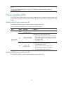
Conventions
This section describes the conventions used in this documentation set.
Command conventions
Convention
Description
Boldface
Bold text represents commands and keywords that you enter literally as shown.
Italic
Italic text represents arguments that you replace with actual values.
[]
Square brackets enclose syntax choices (keywords or arguments) that are optional.
{ x | y | ... }
Braces enclose a set of required syntax choices separated by vertical bars, from which
you select one.
[ x | y | ... ]
Square brackets enclose a set of optional syntax choices separated by vertical bars, from
which you select one or none.
{ x | y | ... } *
Asterisk marked braces enclose a set of required syntax choices separated by vertical
bars, from which you select at least one.
[ x | y | ... ] *
Asterisk marked square brackets enclose optional syntax choices separated by vertical
bars, from which you select one choice, multiple choices, or none.
Convention
Description
&<1-n>
The argument or keyword and argument combination before the ampersand (&) sign can
be entered 1 to n times.
#
A line that starts with a pound (#) sign is comments.
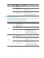
GUI conventions
Convention
Description
Boldface
Window names, button names, field names, and menu items are in Boldface. For
example, the New User window appears; click OK.
>
Multi-level menus are separated by angle brackets. For example, File > Create > Folder.
Convention
Description
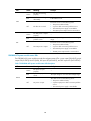
Symbols
WARNING
An alert that calls attention to important information that if not understood or followed can
result in personal injury.
CAUTION
An alert that calls attention to important information that if not understood or followed can
result in data loss, data corruption, or damage to hardware or software.
IMPORTANT
An alert that calls attention to essential information.
An alert that contains additional or supplementary information.
NOTE
An alert that provides helpful information.
TIP
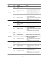
Network topology icons
Represents a generic network device, such as a router, switch, or firewall.
Represents a routing-capable device, such as a router or Layer 3 switch.
Represents a generic switch, such as a Layer 2 or Layer 3 switch, or a router that supports
Layer 2 forwarding and other Layer 2 features.
Port numbering in examples
The port numbers in this document are for illustration only and might be unavailable on your device.
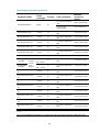
About the H3C S7500E documentation set
The H3C S7500E documentation set includes:
Category
Product description
and specifications
Documents
Purposes
Marketing brochures
Describe product specifications and benefits.
Technology white papers
Provide an in-depth description of software features
and technologies.
Card datasheets
Describe card specifications, features, and standards.
Category
Hardware
specifications and
installation
Software
configuration
Operations and
maintenance
Power configuration
Documents
Purposes
H3C N68 Cabinet
Installation and Remodel
Introduction
Guides you through installing and remodeling H3C
N68 cabinets.
H3C Pluggable SFP
[SFP+][XFP] Transceiver
Modules Installation Guide
Guides you through installing SFP/SFP+/XFP
transceiver modules.
H3C Mid-Range Series
Ethernet Switches Pluggable
Modules Manual
Describes the hot-swappable modules available for the
Mid-Range Series Ethernet Switches, their external
views, and specifications.
H3C PoE DIMM Module
Installation Guide
Describes how to install the DIMM
(LSBM1POEDIMMH) for PoE master and slave power
management.
Single PoE DIMM Module
Installation Guide
Describes how to install the 24-port DIMM
(LSQM1POEDIMMS0) for PoE power management.
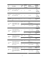
Configuration guides
Describe software features and configuration
procedures.
Command references
Provide a quick reference to all available commands.
Configuration examples
Describe typical network scenarios and provide
configuration examples and instructions.
Release notes
Provide information about the product release,
including the version history, hardware and software
compatibility matrix, version upgrade information,
technical support information, and software
upgrading.
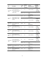
H3C PSR320-A[PSR320-D]
Power Module User Manual
Describes the appearance, specifications, LEDs, and
installation and removal of the H3C
PSR320-A/PSR320-D power module.
H3C PSR650-A[PSR650-D]
Power Module User Manual
Describes the appearance, specifications, LEDs, and
installation and removal of the H3C
PSR650-A/PSR650-D power module.
H3C
PSR1400-A[PSR1400-D]
Power Module User Manual
Describes the appearance, specifications, LEDs, and
installation and removal of the H3C
PSR1400-A/PSR1400-D power module.
H3C PSR2800-ACV Power
Module User Manual
Describes the appearance, specifications, LEDs, and
installation and removal of the H3C PSR2800-ACV
power module.
H3C PSR6000-ACV Power
Module User Manual
Describes the appearance, specifications, LEDs, and
installation and removal of the H3C PSR6000-ACV
power module.
H3C PWR-SPA Power
Module Adapter User
Manual
Describes the functions and appearance of the H3C
PWR-SPA power module adapter, and how to use it
with the PSR650 power module.
H3C S7500E Power
Configuration Guide
Guides you to select power modules in various cases.
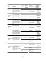
Category
Documents
Purposes
The S7500E series Ethernet switches support various
card models. Each model is provided with a card
manual that describes:
Optional cards
Card manuals
• The type, number, and transmission rate of
interfaces
• Applicable switches of the card
• Required software version
• Pluggable modules supported by the card
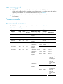
Obtaining documentation
You can access the most up-to-date H3C product documentation on the World Wide Web at
http://www.h3c.com.
Click the links on the top navigation bar to obtain different categories of product documentation:
[Technical Support & Documents > Technical Documents] – Provides hardware installation, software
upgrading, and software feature configuration and maintenance documentation.
[Products & Solutions] – Provides information about products and technologies, as well as solutions.
[Technical Support & Documents > Software Download] – Provides the documentation released with the
software version.
Technical support
[email protected]
http://www.h3c.com
Documentation feedback
You can e-mail your comments about product documentation to [email protected].
We appreciate your comments.
Contents
Product overview·························································································································································· 1
Overview············································································································································································1
Physical architecture ·························································································································································2
Chassis ······································································································································································2
SRPU ··········································································································································································3
LPU ·············································································································································································3
Fan tray ·····································································································································································3
Air filter······································································································································································3
Preparing for installation ············································································································································· 5
Safety recommendations ··················································································································································5
General safety recommendations ···························································································································5
Safety with electricity ···············································································································································5
Safety with switch moving ·······································································································································5
ESD prevention ·························································································································································6
Safety with laser ·······················································································································································6
Examining the installation site ·········································································································································6
Weight support requirements··································································································································6
Temperature requirements ·······································································································································6
Humidity requirements ·············································································································································7
Cleanness requirements ···········································································································································7
EMI requirements······················································································································································8
Grounding requirements··········································································································································8
Power supply requirements······································································································································8
Cooling requirements···············································································································································9
Space requirement ················································································································································ 10
Tools and equipment ····················································································································································· 10
Installing the switch ····················································································································································12
Installation flow ······························································································································································ 12
Inspecting the switch······················································································································································ 13
Installing slide rails and cage nuts to the rack············································································································ 13
Installing slide rails ················································································································································ 13
Installing cage nuts for mounting brackets ········································································································· 17
Installing accessories to the chassis ····························································································································· 18
Installing mounting brackets and cable management brackets········································································ 18
Installing an air filter ············································································································································· 21
Mounting the switch to the rack···································································································································· 22
Connecting the PGND cable ········································································································································ 23
Connecting the PGND cable to a grounding strip ···························································································· 23
Grounding the switch through the PE wire of an AC power supply ································································ 24
Grounding the switch through the RTN wire of a DC power supply······························································· 25
Installing modules·······················································································································································27
Attaching an ESD-preventive wrist strap······················································································································ 27
Installing a card······························································································································································ 28
Installing a power module············································································································································· 29
Installing a power module ···································································································································· 30
Connecting the power cable································································································································ 31
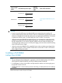
Setting up a PoE system (optional) ······························································································································· 39
i
Requirements·························································································································································· 39
Installing a PoE DIMM ·········································································································································· 41
Connecting an external PoE power supply ········································································································ 44
Installing a CF card to the SRPU (optional) ················································································································· 45
Installing a transceiver module (optional)···················································································································· 46
Installing an XFP/SFP+/SFP module···················································································································· 46
Connecting an SFP+ cable ··································································································································· 47
Setting up an IRF virtual device·································································································································48
Prerequisites···································································································································································· 48
IRF virtual device setup flowchart ································································································································· 48
Planning IRF virtual device setup ·································································································································· 49
Preparing for IRF virtual device setup·················································································································· 49
Planning the IRF network ······································································································································ 49
Installing IRF member switches ····································································································································· 50
Configuring basic IRF settings······································································································································· 50
Connecting the physical IRF ports ································································································································ 50
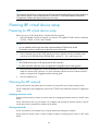
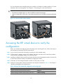
Accessing the IRF virtual device to verify the configuration······················································································· 51
Connecting your switch to the network ····················································································································53
Concepts ········································································································································································· 53
Common methods of logging in to a switch······································································································· 53
User interfaces supported by the switch ············································································································· 53
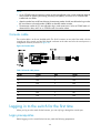
Console cable ························································································································································ 54
Logging in to the switch for the first time ····················································································································· 54
Login prerequisites ················································································································································ 54
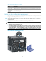
Setting up the configuration environment ··········································································································· 55
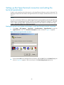
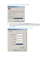
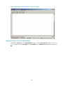
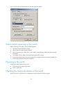
Setting up the HyperTerminal connection and setting the terminal parameters ············································· 56
Checks before powering on the switch··············································································································· 59
Powering on the switch········································································································································· 59
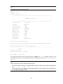
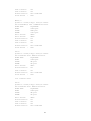
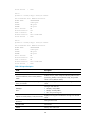
Checking the startup information of the switch ·································································································· 59
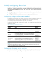
Initially configuring the switch ······································································································································ 61
Configuring a login authentication method········································································································ 61
Configuring the basic access function ················································································································ 61
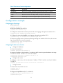
Configuration example ········································································································································· 62
Displaying the network configuration ················································································································· 63
Connecting the switch to the network ·························································································································· 64
Connecting your switch to the network through twisted pair cables ······························································· 64
Connecting your switch to the network through optical fibers ········································································· 64
Hardware management and maintenance ··············································································································66
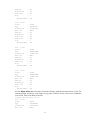
Displaying information about the switch ····················································································································· 66
Displaying software and hardware version information··················································································· 66
Displaying switch running information················································································································ 69
Displaying detailed information about a card ··································································································· 69
Displaying electronic card label information ····································································································· 72
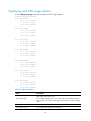
Displaying card CPU usage statistics ·················································································································· 74
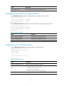
Displaying card memory usage statistics············································································································ 75
Displaying CF card information··························································································································· 75
Displaying the operating status of fans··············································································································· 76
Displaying the operating status of power modules···························································································· 76
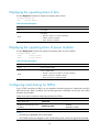
Configuring load sharing for SRPUs···················································································································· 76
Configuring the temperature thresholds for a card···························································································· 77
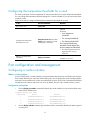
Port configuration and management···························································································································· 77
Configuring a combo interface···························································································································· 77
Enabling active/standby mode for the network ports on SRPUs······································································ 78
ii
Displaying transceiver module and alarming information ················································································ 79
Configuring a software exception handling method·································································································· 80
Configuring an exception handling method······································································································· 80
Displaying the exception handling method ········································································································ 81
Displaying IRF information ············································································································································ 81
Displaying information about all IRF member switches····················································································· 81
Displaying the basic IRF settings of IRF member switches················································································· 82
Displaying IRF topology information ··················································································································· 83
Saving the running configuration ································································································································· 83
Rebooting a card or the switch ···································································································································· 84
Troubleshooting ··························································································································································86
Troubleshooting methods··············································································································································· 86
Troubleshooting the system ··········································································································································· 87
Troubleshooting on startup ··································································································································· 87
Troubleshooting the switch during the operation······························································································· 87
Troubleshooting the power supply system··················································································································· 87
Troubleshooting the fans ··············································································································································· 88
Troubleshooting the SRPUs············································································································································ 89
Troubleshooting the LPUs··············································································································································· 89
Troubleshooting interfaces ············································································································································ 89
Troubleshooting CF cards ············································································································································· 90
Troubleshooting the PoE system···································································································································· 91
Technical support ··························································································································································· 91
Replacement procedures ···········································································································································92
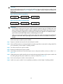
Replacing a power module··········································································································································· 92
Replacing a card···························································································································································· 94
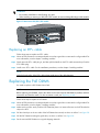
Replacing a fan tray ······················································································································································ 95
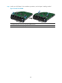
Replacing an S7506E-V fan tray························································································································· 95
Replacing the fan tray of other models ··············································································································· 97
Replacing an air filter ···················································································································································· 98
Replacing air filters on an S7506E-V·················································································································· 98
Replacing an air filter for the other models ········································································································ 99
Replacing a CF card····················································································································································100
Replacing a transceiver module ·································································································································101
Replacing an XFP/SFP+/SFP module················································································································101
Replacing an SFP+ cable ···································································································································102
Replacing the PoE DIMM ············································································································································102
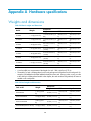
Appendix A Hardware specifications ·················································································································· 104
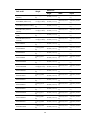
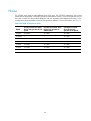
Weights and dimensions·············································································································································104
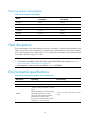
Module power consumption and total power consumption ····················································································108
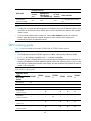
Total power consumption ···································································································································108
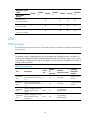
Card power consumption ···································································································································109
Fan tray power consumption······························································································································111
Heat dissipation ···························································································································································111
Environmental specifications ·······································································································································111
Noise ·············································································································································································112
Appendix B Pluggable module ordering guide ··································································································· 113
SRPU ··············································································································································································113
SRPU overview·····················································································································································113
SRPU ordering guide···········································································································································114
LPU ·················································································································································································115
LPU overview························································································································································115
iii
LPU ordering guide ·············································································································································120
Power module·······························································································································································120
Power module overview ·····································································································································120
Power module ordering guide ···························································································································121
Fan tray ·········································································································································································122
Fan tray overview················································································································································122
Fan tray ordering guide······································································································································122
Air filter ·········································································································································································123
Air filter overview ················································································································································123
Air filter ordering guide ······································································································································123
PoE DIMM·····································································································································································123
PoE DIMM overview············································································································································123
PoE DIMM ordering guide ·································································································································123
CF card ·········································································································································································124
CF card overview ················································································································································124
CF card ordering guide ······································································································································124
Transceiver modules ····················································································································································124
Transceiver module overview·····························································································································124
Transceiver module ordering guide···················································································································127
AC power cable···························································································································································127
AC power cable overview ·································································································································127
AC power cable ordering guide ·······················································································································128
Appendix C LEDs ··················································································································································· 134
SRPU LEDs ·····································································································································································135
LPU LEDs········································································································································································139
Power module LEDs······················································································································································141
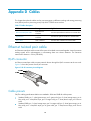
Appendix D Cables ··············································································································································· 149
Ethernet twisted pair cable··········································································································································149
RJ-45 connector ···················································································································································149
Cable pinouts·······················································································································································149
Cable type····························································································································································150
Pin assignments····················································································································································151
Making an Ethernet twisted pair cable ·············································································································152
Optical fiber ·································································································································································153
Overview······························································································································································153
Precautions ···························································································································································154
SFP+ cable ····································································································································································155
Appendix E Cabling recommendations ··············································································································· 156
General cabling requirements ····································································································································156
Correct use of labels ····················································································································································156
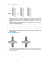
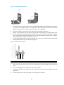
Cable management requirements ······························································································································156
Compliance and safety manual ····························································································································· 160
Regulatory compliance statement ·······························································································································160
European Community CE Certification DoC ····································································································160
Regulatory Compliance Information···························································································································160
Regulatory compliance standards ·····················································································································160
European Directives compliance ·······················································································································161
USA regulatory compliance ·······························································································································161
Canada regulatory compliance ·························································································································161
Japan regulatory compliance·····························································································································161
CISPR 22 compliance ·········································································································································162
Safety Information Sicherheitsinformationen安全信息 ·····························································································162
iv
Overview Überblick 概述 ···································································································································162
Electricity Safety Elektrische Sicherheit 用电安全 ····························································································166
Fuse Sicherung保险丝·········································································································································168
Laser Laser激光辐射 ············································································································································168
Index ········································································································································································ 170
v
Product overview
This chapter includes these sections:
•
Overview
•
Physical architecture
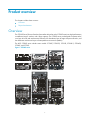
Overview
The S7500E Series Ethernet Switches (hereinafter referred to as the S7500E series) are high performance,
cost-effective Layer-3 switches with a large capacity. The S7500E series are designed to operate at the
core layer of small- and medium-sized networks, the distribution layer of large enterprise networks, and
the distribution and access layers of metropolitan area networks (MANs).
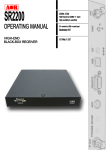
The H3C S7500E series include seven models: S7502E, S7503E-S, S7503E, S7506E-S, S7506E-V,
S7506E, and S7510E.
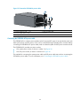
Figure 1 S7500E series
1
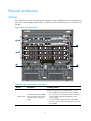
Physical architecture
Chassis
The S7500E series consists of a switching and routing processing unit (SRPU) section, line processing unit
(LPU) section, power supply module section, and fan tray section. The following uses an S7503E as an
example.
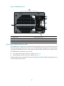
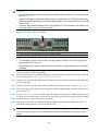
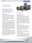
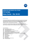
Figure 2 Front view of the S7503E
1
4
2
3
3
Table 1 Description of the sections of the chassis
Section
Description
Ordering remarks
SRPUs are required but not shipped with the switch.
① SRPU section
Provides slots for SRPUs. SRPUs
have pink edges. They must be
inserted in the slots with pink
edges.
• The S7500E series support various types of SRPUs.
You can select them as needed. For more information,
see the chapter “Appendix B Pluggable module
ordering guide.”
• You can install two SRPUs (for active and standby
switchover) for all models of the S7500E series except
the S7503E-S.
2
Section
Description
Ordering remarks
LPUs are required but not shipped with the switch.
② LPU section
Provides slots for LPUs. Line
processing units (LPUs) have
purple edges. They must be
inserted in the slots with purple
edges.
The S7500E series support various types of LPUs. You
can select them as needed. For more information, see the
chapter “Appendix B Pluggable module ordering guide.”
Power modules are required but not supplied with the
switch.
• The S7500E series provide two power module slots.
• The S7500E series provide power modules of different
③ Power supply
section
Provides slots for power
modules.
④ Fan section
Provides a slot for the fan tray
specifications and flexible ordering schemes. You can
select them as needed. For more information about
power module models, see the chapter “Appendix B
Pluggable module ordering guide.”
Fan trays are required and supplied with the switch.
SRPU
For the S7500E series, SRPUs are the core in the control and management plane and switching fabric.
The S7500E series provide 10 types of SRPUs. You can select them as needed.
For SRPU models, see the chapter “Appendix B Pluggable module ordering guide.”
LPU
The S7500E series provide various types of LPUs and support flexible combination of the LPUs to satisfy
different networking requirements.
For LPU models, see the chapter “Appendix B Pluggable module ordering guide.”
NOTE:
The installation procedures for SRPUs and LPUs are similar. They are called cards in the following chapters
unless otherwise specified.
Fan tray
The S7500E series provide a fan tray for each type of chassis. The location of fan trays varies depending
on the chassis types.
•
The fan tray of the S7502E, S7503E-S, S7503E, S7506E-S, S7506E, and S7510E switches is
installed on the right side of the front of the chassis.
•
The fan tray of the S7506E-V is installed on the upper part of the front of the chassis.
Air filter
To prevent dust from entering the chassis, the S7500E series provide an air filter (optional) at the air
intake on the chassis.
•
The air filter of the S7502E, S7503E-S, S7503E, S7506E-S, S7506E, and S7510E switches is
installed on the left side of the chassis.
3
•
The S7506E-V provides two air filters. The one in front of the chassis is installed between the card
section and power supply section, and the one at the back of the chassis is installed at the position
corresponding to the front air filter.
CAUTION:
Clean air filters periodically (at least once every three months) to guarantee adequate ventilation and heat
dissipation.
4
Preparing for installation
This chapter includes these sections:
•
Safety recommendations
•
Examining the installation site
•
Tools and equipment
Safety recommendations
To avoid possible bodily injury and equipment damage, read the safety recommendations in this chapter
carefully before installing an H3C S7500E switch. The recommendations do not cover every possible
hazardous condition.
General safety recommendations
•
Keep the chassis clean and dust-free. Do not place the switch on a moist area and avoid liquid
flowing into the switch.
•
Make sure that the ground is dry and flat and you have adopted anti-slip measures.
•
Keep the chassis and installation tools away from walk areas.
•
Do not wear loose clothing, jewelry (for example, necklace) or any other things that could get
caught in the chassis when you install and maintain the switch.
Safety with electricity
•
Clear the work area of possible hazards, such as ungrounded power extension cables, missing
safety grounds, and moist floors.
•
Locate the emergency power-off switch in the room before installation. Shut the power off at once in
case accident occurs.
•
Unplug all the external cables (including power cables) before moving the chassis.
•
Do not work alone when the switch has power.
•
Always check that the power has been disconnected.
Safety with switch moving
To move an H3C S7500E switch, follow these steps:
•
Remove all the external cables (including the power cables) before moving the chassis.
•
Use at least two persons to move the switch, and use a mechanical lift if necessary.
•
Move the switch carefully.
5
CAUTION:
• When moving the switch, hold the handles at both sides of the chassis.
• Do not hold the handle of the fan tray, power module, or back cover of the chassis, or the air vents of
chassis. Any attempt to carry the switch with these parts may cause equipment damage or even bodily
injury.
ESD prevention
To prevent the electric component from being damaged by the electrostatic discharge (ESD), adhere to
the following requirements:
•
Ground the switch properly. For how to ground your switch, see the chapter “Installing the switch.”
•
Always wear an ESD-preventive wrist strap and make sure it is well grounded when installing
pluggable modules. For how to use an ESD-preventive wrist strap, see the chapter “Installing
modules.”
•
Hold a PCB by its edges. Do not touch any electronic components or printed circuit.
•
Put cards in an ESD-preventive bag.
Safety with laser
The H3C S7500E series switches are class 1 laser products.
WARNING!
The laser inside the optical fiber may hurt your eyes.
Examining the installation site
The H3C S7500E series can only be used indoors. To ensure that the switch works properly and to
prolong its service lifetime, the installation site must meet the following requirements.
Weight support requirements
Evaluate the floor loading as compared to the actual weight of the switch and its accessories (such as
rack, chassis, cards, and power modules, and make sure that the floor can support the weight of the rack
and the switch chassis.
IMPORTANT:
When evaluating the floor loading, consider switch capacity expansion (for example, installing a new
card) in the future.
Temperature requirements
To ensure the normal operation of the switch, ensure that the room temperature meets the requirements
described in Table 2.
6
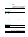
Table 2 Temperature requirements
Temperature
Range
Operating temperature
0°C to 45°C (32°F to 113°F)
Storage temperature
–40°C to +70°C (–40°F to +158°F)
CAUTION:
If condensation appears on the switch when you move it to a high-temperature environment, dry the switch
before powering it on to avoid short circuits.
Humidity requirements
Maintain appropriate humidity in your equipment room, as described in Table 3.
•
Lasting high relative humidity tends to cause poor insulation, electricity creepage, mechanical
property change of materials, and corrosion of metal parts.
•
Lasting low relative humidity is likely to result in loose screws due to washer contraction, and even
electrostatic discharge (ESD), which causes the circuits to fail.
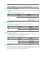
Table 3 Humidity requirements
Humidity
Range
Operating humidity (noncondensing)
10% to 95%
Storage humidity (noncondensing)
5% to 95%
Cleanness requirements
Maintain appropriate cleanness in your equipment room.
•
Dust is a hazard to the operating safety of your switch. Dust buildup on the chassis may result in
electrostatic adsorption, which causes poor contact of metal components and contact points,
especially when indoor relative humidity is low. In the worst case, electrostatic adsorption can
cause communication failure. Table 4 shows the dust concentration limit in the equipment room.
•
The equipment room should meet strict limits on salts, acids and sulfides to eliminate corrosion and
premature aging of components, as shown in Table 5.
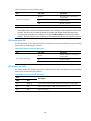
Table 4 Dust concentration limit in the equipment room
Substance
Dust particles
Concentration limit (particles/cu m)
≤ 3 x 10⁴
(No visible dust on desk in three days)
IMPORTANT:
Dust particle diameter ≥ 5 μm
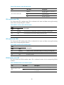
Table 5 Harmful gas limits in an equipment room
Gas
Max. (mg/m3)
SO2
0.2
7
Gas
Max. (mg/m3)
H2S
0.006
NH3
0.05
Cl2
0.01
EMI requirements
All electromagnetic interference (EMI) sources, from outside or inside of the switch and application
system, adversely affect the switch in a conduction pattern of capacitance coupling, inductance coupling,
electromagnetic wave radiation, or common impedance (including grounding system) coupling. To
prevent EMI, perform the following steps:
•
Take measures against interference from the power grid.
•
Do not use the switch together with the grounding equipment or lightning-prevention equipment of
power equipment, and keep the switch far away from them.
•
Keep the switch far away from high-power radio launchers, radars, and equipment with high
frequency or high current.
•
Use electromagnetic shielding when necessary.
Grounding requirements
Using a good grounding system to protect your switch against lightning shocks, interferences, and ESD
is essential to the operating reliability of your switch. Make sure that the resistance between the chassis
and the ground is less than 1 ohm. For more information about the grounding methods of the S7500E
series, see the chapter “Installing the switch.”
Power supply requirements
Perform the following steps to satisfy the power supply requirements of the S7500E series:
1.
Calculate the total power consumption
The total power consumption of an S7500E series switch depends on card type and quantity and fan tray
power consumption. If the switch provides PoE power, the total power consumption also depends on PoE
power consumption. For more information about the total power consumption of the S7500E series, see
the chapter “Appendix A Hardware specifications.”
2.
Select power modules according to the total power consumption
To ensure normal operation of the switch, make sure that the maximum output power of the power
module that supplies power to the switch is higher than the total power consumption of the switch. After
determining the total power consumption of the switch, you can select appropriate power modules
according to the total power consumption. For more information about the optional power module
models, see the chapter “Appendix B Pluggable module ordering guide.”
3.
Check that the power supply system on the installation site satisfies the input requirements of the
power modules and parameters such as rated voltage.
8
Cooling requirements
For adequate heat dissipation, plan the installation site according to the airflow of your switch, and
adhere to the following requirements:
•
Leave a clearance of at least 10 cm (3.94 in) around the air intake and exhaust vents.
•
The rack for installing the switch has a good cooling system.
•
The installation site has a good cooling system.
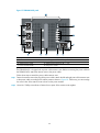
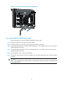
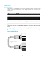
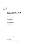
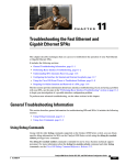
Figure 3 Airflow for the S7506E-V
4
4
4
3
3
2
1
1
1: Air intake for power modules
2: Air exhaust for power modules
3: Air intake for the chassis
4: Air exhaust for the chassis
9
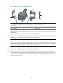
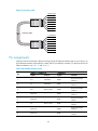
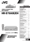
Figure 4 Airflow for other models of the S7500E series
1: Air intake for power modules
2: Air exhaust for power modules
3: Air intake for the chassis
4: Air exhaust for the chassis
Space requirement
For adequate ventilation and ease of maintenance, make sure that the clearance between the rack and
walls or other devices is at least 1 m (3.28 ft), and the headroom in the equipment room is no less than
3 m (9.84 ft).
Tools and equipment
Table 6 lists the tools and equipment that you may use when installing an S7500E series switch.
Table 6 Tools and equipment list
Category
Tool
Measuring and
marking tools
Long tape, ruler (of 1 meter), gradienter, marker, chalk line, and pencil
Drills
Percussion drill, electric drill, and several auxiliary drill bits
Flat-blade screwdriver P4-75 mm
Fastening tools
Phillips screwdriver P1-100 mm, P2-150 mm, and P3-250 mm
Socket wrench M5
Socket wrench M6
Small tools
Needle-nose pliers, diagonal pliers, combination pliers, wire-stripping pliers, crimping
pliers, RJ-45 crimping pliers, file, and handsaw
Auxiliary tools
ESD-preventive wrist strap, hair brush, tweezers, paper knife, hand bellows, electric iron,
solder wire, ladder, cable stripper, vacuum cleaner, crowbar, and rubber hammer
10
Category
Tool
Tools for
fiber-optic
cleaning
Lint-free paper and optical fiber microscope
Equipment
Multimeter, 500 V Megohmmeter for measuring the insulation resistance, error detector,
optical power meter, and earth resistance tester
NOTE:
Tools and equipment are not supplied with the switch. Prepare them by yourself as needed.
11
Installing the switch
This chapter includes these sections:
•
Installation flow
•
Inspecting the switch
•
Installing slide rails and cage nuts to the rack
•
Installing accessories to the chassis
•
Mounting the switch to the rack
•
Connecting the PGND cable
IMPORTANT:
Keep the packages of the switch and the components for future use.
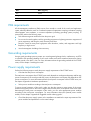
Installation flow
Figure 5 Installation flow
Start
Check before
installation
Install slide rails and cage
nuts to the rack
Install accessories to the
chassis
Install the switch
to the rack
Connect the PGND cable
End
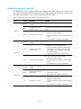
Table 7 Description on the installation flow
Step
Remarks
Inspecting the switch
Preparations before installation
Installing slide rails and
cage nuts to the rack
• For how to install slide rails, see “Installing slide rails.”
• For how to install cage nuts, see “Installing cage nuts for mounting brackets.”
12
Step
Remarks
Accessories to be installed on the chassis:
Installing accessories to
the chassis
• For how to mount brackets and cable management brackets, see “Installing
mounting brackets and cable management brackets.”
• For how install an air filter (optional), see “Installing an air filter.”
Mounting the switch to
the rack
—
Connecting the PGND
cable
—
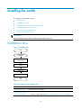
Inspecting the switch
Follow these steps before installing an H3C S7500E switch:
•
Make sure that you have read the chapter “Preparing for installation” carefully and the installation
site meets all the requirements.
•
Make sure a 19-inch rack is ready for use. For how to install a rack, see the rack installation guide.
•
Make sure that the rack is sturdy and securely grounded; the installation position on the rack is
appropriate for the chassis; no debris exists inside or around the rack.
•
Make sure the switch is ready for installation and has been carried to a place near the rack and
convenient for moving.
IMPORTANT:
To ensure the stability of the rack, mount the switch at the lowest possible position. To mount multiple
switches on the rack, mount the heaviest switch at the bottom of the rack.
Installing slide rails and cage nuts to the rack
Installing slide rails
Before installing the switch to the rack, install slide rails to the rack. If the rack has slide rails, skip this
section.
NOTE:
• Before installing the slide rails, check that the slide rails can support the weight of the switch. For the
weights of the S7500E series, see the chapter “Appendix A Hardware specifications.”
• For the slide rails, H3C recommends that you order the H3C Slide Rail Accessories,500mm-800mm
(LSTM2KSGD0).
• Position the chassis of the S7500E series according to their heights. For the specifications of the S7500E
series, see the chapter “Appendix A Hardware specifications.”
• The installation of slide rails might vary with different types of racks. The following installation procedure
is for your reference only.
Follow these steps to install a slide rail:
Step1
Read the signs on the slide rail (see Table 8) to avoid installation mistake.
13
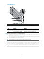
Figure 6 Right slide rail
1: Signs
2: Guide rail
3: Installation hole
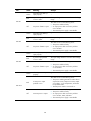
Table 8 Description of signs on the slide rails
Step2
Sign
Meaning
Remarks
F/L
Front end of the left slide rail
Mount this end to the front left rack post.
F/R
Front end of the right slide rail
Mount this end to the front right rack post.
Mark the position on the rack for installing the slide rail.
•
Make sure the bottom edge of the slide rail aligns with the middle of the narrower metal area
between holes, as shown in Figure 7.
•
Each rack post requires six screws to fix the slide rail. You only need to mark the uppermost square
hole and lowermost square hole for installation.
•
Mark the square holes at the same height on the other three rack posts.
NOTE:
One rack unit has three holes, the middle of which is an auxiliary installation hole, and the other two are
standard installation holes. You can distinguish them by the space between each two holes. The space
between a standard installation hole and an auxiliary installation hole is larger than that between two
adjacent standard installation holes.
14
Figure 7 Locate the position on the rack for installing the slide rail
1: Middle of the narrower metal area between holes
Step3
Install six cage nuts on the square holes on each rack post, as shown in Figure 8.
Figure 8 Install a cage nut
Step4
Align the installation holes on the front end of the slide rail with the cage nuts on the front rack post, and
fix them with screws, as shown in Figure 9.
15
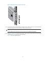
Figure 9 Fix the slide rail to the cage nuts with screws
Step5
Keep the slide rail horizontally and adjust its length until the installation holes on the rear end of the slide
rail touch the cage nuts on the rear rack post. Then fix them with screws.
TIP:
Fix all installation holes of the slide rail with screws to ensure its weight bearing capacity.
Step6
Repeat Step4 and Step5 to install the other slide rail. Make sure the two slide rails are at the same height
so that the device can be placed on them horizontally.
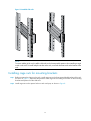
Figure 10 shows the installed slide rails.
16
Figure 10 Installed slide rails
NOTE:
To ensure stability of the rack, install the slide rails to the lowest possible position when installing a single
switch on the rack. To install multiple switches on the rack, mount the heaviest switch at the bottom of the
rack.
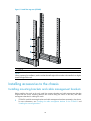
Installing cage nuts for mounting brackets
Step1
Before mounting the chassis to the rack, install cage nuts to the front square-holed brackets of the rack.
As shown in Figure 11, determine the positions of the cage nuts according to the holes on the mounting
brackets and positions of the slide rails.
Step2
Install cage nuts on the square holes on each rack post, as shown in Figure 8.
17
Figure 11 Install the cage nuts (S7503E)
1: Cage nut
NOTE:
When preparing for installation, make sure that the total height of the switches to be installed is no higher
than the height of the rack.
Installing accessories to the chassis
Installing mounting brackets and cable management brackets
Before installing the switch to the rack, install the mounting brackets and cable management brackets
shipped with the switch. Mounting brackets are used for fixing the chassis to the rack, and cable
management brackets for cabling the switch.
•
S7506E-V: Install the mounting brackets and cable management brackets separately to the chassis.
For more information, see “Installing the cable management brackets on the S7506E-V” and
“Installing the mounting brackets.”
18
•
Other models: Install the cable management brackets to the mounting brackets, and then install the
mounting brackets to the chassis. For more information, see “Installing the cable management
brackets on other models” and “Installing the mounting brackets.”
Installing the cable management brackets on the S7506E-V
The S7506E-V has two cable management brackets—the one with a tray is installed at the lower part of
the switch, and the one without a tray is installed at the upper part of the switch. They are installed in the
same way.
Follow these steps to install a cable management bracket:
Step1
Take out the cable management brackets from the package.
Step2
Attach the cable management bracket to the chassis, and align the screws with the screw holes on the
chassis, as shown in Figure 12.
Step3
Fasten the screws.
Figure 12 Install cable management brackets on an S7506E-V
2
4
3
5
3
1
2
1
1: Attach the cable management bracket to the
chassis
2: Screw holes for installing the cable management
bracket
3: Screws for fixing the cable management bracket to
the chassis
4: Cable management bracket without a tray
(installed at the upper part of the chassis)
5: Cable management bracket with a tray (installed at
the lower part of the chassis)
Installing the cable management brackets on other models
For the models except the S7506E-V, install the cable management bracket on the left mounting bracket,
as shown in Figure 13. The switch is supplied with two mounting brackets, and the one with the cable
management bracket screw holes is the left mounting bracket.
19
Figure 13 Install the cable management bracket to the left mounting bracket
4
3
1
2
1: Left mounting bracket
2: Cable management bracket
3: Screw hole for installing the cable management
bracket
4: Screw for fixing the cable management bracket to
the left mounting bracket
Installing the mounting brackets
Before installing the switch to the rack, install the mounting brackets to the chassis, as shown in Figure 14.
•
S7506E-V: Facing the front of the switch, mount the left and right mounting bracket to the two sides
of the switch.
•
Other models: Facing the front of the switch, mount the mounting bracket with a cable management
bracket to the left of the switch, and mount the mounting bracket without a cable management
bracket to the right of the switch (where the fan tray is located).
Figure 14 Install the mounting brackets (S7503E)
1: Screws for fixing the mounting brackets to the chassis
3: Right mounting bracket
20
2: Left mounting bracket
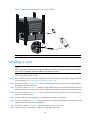
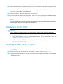
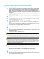
Installing an air filter
Air filters of the S7500E series are optional. If you have ordered air filters, H3C recommends you to
install the air filters before mounting the switch to the rack.
•
S7506E-V: An air filter is available at both front and rear of the switch, and can be installed in the
same way. For the installation procedures, see “Installing an air filter on an S7506E-V.”
•
Other models: The air filter is located at the left of the chassis. For the installation procedures, see
“Installing an air filter on other models of the S7500E series.”
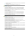
Installing an air filter on an S7506E-V
Follow these steps to install an air filter on an S7506E-V:
Step1
Take out the air filter from the package.
Step2
As shown in callout 1 on Figure 15, attach the air filter to the intake vents on the front panel or rear panel,
and then insert the captive screws into the screw holes on the chassis.
Step3
Faster the captive screws, as shown in callout 2 on Figure 15.
Figure 15 Install an air filter on an S7506E-V
1: Attach the air filter to the intake vents on the front or
rear panel of the chassis
2: Fasten the screws
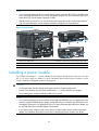
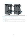
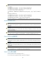
Installing an air filter on other models of the S7500E series
Follow these steps to install an air filter:
Step1
Take out the air filter and fastening strips from the package.
Step2
Align the screw holes on the fastening strip with the screw holes on the chassis, insert the screws into the
screw holes, and then fasten the screws clockwise with a screwdriver, as shown in callout 1 on Figure 16.
Step3
Push the air filter in between the fastening strips, as shown in callout 2 on Figure 16.
Step4
Fasten the captive screws clockwise, as shown in callout 3 on Figure 16.
21
Figure 16 Install an air filter (S7503E)
1: Fix the fastening strips onto the chassis
2: Push the air filter in between the fastening strips
3: Fasten the captive screws
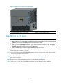
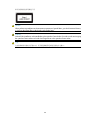
Mounting the switch to the rack
Follow these steps to mount the switch to the rack:
Step1
Face the rear of the chassis towards the front of the rack.
Step2
Use at least two persons to lift the switch until the bottom of the switch is a little higher than the slide rails
on the rack.
CAUTION:
• Do not hold the handle of the fan tray, power module, or the back cover of the chassis, or the air vents
of chassis. Any attempt to carry the switch with these parts may cause equipment damage or even
bodily injury.
• Use a mechanical lift for switches of a high weight.
Step3
Place the switch on the slide rails and slide the switch along the slide rails until the mounting brackets on
the switch touch the front rack posts, as shown in callout 1 on Figure 17.
CAUTION:
After placing the switch on the slide rails, do not leave go of your hands immediately because this may tip
and damage the switch, and even cause bodily injury.
Step4
Fix the chassis to the rack with mounting screws.
22
Figure 17 Install the chassis to the rack (S7503E)
1: Slide the chassis into the rack
2: Left mounting bracket
3: Right mounting bracket
4: Screws for fixing the mounting brackets to the rack
NOTE:
If the screw holes on the mounting brackets cannot align with the cage nuts on the rack, check that the
bottom edge of the slide rail aligns with the middle of the narrowest metal area between holes and that the
cage nuts are installed in the correct holes.
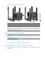
Connecting the PGND cable
CAUTION:
Before using the switch, connect the PGND cable properly to guarantee lightning protection and
anti-interference of the switch.
This section includes these topics:
•
Connecting the PGND cable to a grounding strip
•
Grounding the switch through the PE wire of an AC power supply
•
Grounding the switch through the RTN wire of a DC power supply
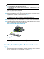
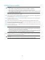
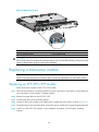
Connecting the PGND cable to a grounding strip
When a grounding strip is available at the installation site, connect the PGND cable through the
grounding strip.
23
CAUTION:
• Use the supplied PGND cable (yellow-green PGND cable).
• Connect the PGND cable to the earthing system in the equipment room. Do not connect it to a fire main
or lightning rod.
Follow these steps to connect the PGND cable:
Step1
Take out the PGND cable from the package.
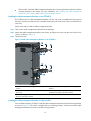
Step2
Remove the grounding screws from the grounding holes on the switch chassis (the grounding holes are
located at the rear of the chassis, as shown in callout 2 on Figure 18.).
NOTE:
The PGND cable provided with the S7500E series is compliant with the NEBS standards.
Step3
Fasten the grounding screws, which are attached with the dual-hole OT terminals of the PGND cable,
into the grounding holes of the chassis.
Step4
Connect the other end (OT terminal) of the PGND cable to the grounding post of the grounding strip, and
fasten the PGND cable to the grounding strip with the hex nut.
Figure 18 Connect the PGND cable to a grounding strip
2
1
3
6
5
4
1: Fix the grounding screws with dual-hole OT
terminals to the grounding holes
2: Grounding holes
3: Grounding strip
4: Grounding post
5: OT terminal
6: Hex nut
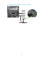
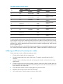
Grounding the switch through the PE wire of an AC power
supply
If the switch is AC powered and no grounding strip is available at the installation site, you can ground
the switch through the PE wire of the AC power supply, as shown in Figure 19.
24
CAUTION:
Make sure that the AC power supply uses a three-wire cable with a protection wire, and the PE wire of the
AC power supply is well grounded at the power distribution room or AC power supply transformer side.
In addition, make sure that the PE connector on the switch is well connected to the PE wire of the AC power
supply.
Figure 19 Ground the switch through the PE wire of the AC power supply
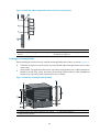
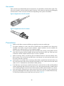
Grounding the switch through the RTN wire of a DC power
supply
If the switch is powered by a –48 VDC power supply and no grounding strip is available at the
installation site, you can ground the switch through the return (RTN) wire of the DC power supply, as
shown in Figure 20.
CAUTION:
Make sure the RTN wire is well grounded from the DC egress of the DC power cabinet.
25
Figure 20 Ground the switch through the RTN wire of the DC power supply
26
Installing modules
This chapter includes these sections:
•
Attaching an ESD-preventive wrist strap
•
Installing a card
•
Installing a power module
•
Setting up a PoE system (optional)
•
Installing a CF card to the SRPU (optional)
•
Installing a transceiver module (optional)
NOTE:
No strict order is required for installing modules. H3C recommends you to install the modules needed, and
then connect the power cable.
IMPORTANT:
Keep the packages of the switch and the components properly for future use.
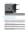
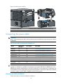
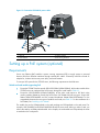
Attaching an ESD-preventive wrist strap
The S7500E series provides an ESD-preventive wrist strap. To minimize ESD damage to electronic
components, wear an ESD-preventive wrist strap and ensure it is well grounded when installing modules.
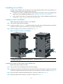
Follow these steps to use an ESD-preventive wrist strap:
Step1
Make sure the switch is well grounded. For how to ground your switch, see the chapter “Installing the
switch.”
Step2
Wear the wrist strap.
Step3
Tighten the wrist strap to keep good skin contact.
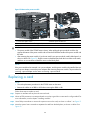
Step4
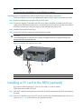
As shown in Figure 21, insert the ESD-preventive wrist strap into the ESD port on the switch chassis, or
attach it to the grounding screw of the chassis with an alligator clip.
CAUTION:
• Make sure that the resistance reading between your body and the ground is between 1 and 10
megohms.
• Make sure the switch is well grounded. For how to ground the switch, see the chapter “Installing the
switch.”
27
Figure 21 Attach an ESD-prevent wrist strap (on an S7503E)
1
1: ESD-preventive wrist strap port (having an ESD sign)
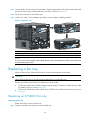
Installing a card
NOTE:
All the switching and routing processing units (SRPUs) and line processing units (LPUs) for the S7500E
series are hot swappable, and the installation procedures are similar.
Follow these steps to install a card:
Step1
Wear an ESD-preventive wrist strap, and make sure it has a good skin contact and is well grounded. For
more information, see “Attaching an ESD-preventive wrist strap.”
Step2
As shown in callout 1 on Figure 22, remove the blank filler (if any) from the slot to be used. Keep the
blank filler properly for future use.
Step3
As shown in callout 2 on Figure 22, hold the card by the front panel with one hand and support the card
bottom with the other (do not touch its circuit). Slide the card steadily into the slot along the guide rails.
Step4
As shown in callout 3 on Figure 22, when most part of the card is inserted in the slot, press the ejector
levers on the card outward.
Step5
Push the card until the positioning pin on card touches the hole on the chassis.
Step6
As shown in callout 4 on Figure 22, press the ejector levers inward until the ejector levers touch the panel
tightly and the card seats into the backplane.
Step7
As shown in callout 5 on Figure 22, fasten the captive screws on the card.
Step8
When the switch is powered on, check the running status of the card.
28
NOTE:
• You can check the running status of a card by referring to the card status LED (SLOT) on the SRPU of the
switch. If the RUN LED blinks, the card in the slot operates properly. For more information about card
status LED (SLOT), see the chapter “Appendix C LEDs.”
• After the switch is powered on, you can check the card running status at the command line interface
(CLI). For more information, see the chapter “Hardware management and maintenance.”
Figure 22 Install a card
1: Remove the blank filler
2: Slide the card into the slot along the guide rails
3: Press the ejector levers on the card outward
4: Press the ejector levers on the card inward
5: Fasten the captive screws
Installing a power module
The S7500E series adopts 1 + 1 power redundancy and supports dual-grid power input. You can select
AC or DC power supply as needed. For more information about optional power modules, see the
chapter “Appendix B Pluggable module ordering guide.”
CAUTION:
• For dual-grid input, the input voltage and frequency for the two grids must the same.
• Provide a circuit breaker for each power module when 1 + 1 power redundancy is adopted.
• Do not install power modules of different models on one switch.
NOTE:
• For a switch using high power power modules such as PSR1400/PSR2800, you can supply power to the
switch by using the PWR-SPA power adapter and the PSR 650 power module when the system power
consumption of the switch is no higher than 650 W. For more information about the power adapter, see
the H3C PWR-SPA Power Module Adapter User Manual.
• If you select a power adapter, install it to the chassis, and then install a power module to the power
adapter. The installation procedures are the same as installing the power module to the chassis.
29
Installing a power module
CAUTION:
• Before installing a power module, make sure that the power module is switched off.
• Make sure the power of the power module can satisfy the requirements of the switch.
• When moving the power module, support the bottom of the power module, instead of holding its handle
to avoid damaging the power module.
Follow these steps to install the power module:
Step1
Wear an ESD-preventive wrist strap and make sure it has a good skin contact and is well grounded. For
more information, see “Attaching an ESD-preventive wrist strap.”
Step2
As shown in callout 1 on Figure 23, remove the blank filler (if any) from the slot to be used. Keep the
blank filler properly for future use.
Step3
Take out the power module from its package, and check that the power module model is correct.
Step4
Be sure to insert the power module with its upside up. Grasp the handle of the module with one hand
and support the module bottom with the other.
Step5
As shown in callout 2 on Figure 23, gently push the power module along the guide rails into the slot until
it has firm contact with the slot.
NOTE:
• Follow the forward inertia of the power module when inserting it into the chassis to ensure that the power
module has firm contact with the connector on the backplane.
• To prevent damage to the power module and the connection terminals on the backplane, be sure to pull
out the power module first in case of any misalignment, and then push it in again.
Step6
As shown in callout 3 on Figure 23, use a Phillips screwdriver to fasten the captive screws on the power
module to secure the power module into the chassis.
CAUTION:
If the captive screws cannot be fastened, check that the power module is properly installed.
30
Figure 23 Install a power module
2
3
1
1: Remove the blank filler
3
2: Push the power module along the guide rails into the slot
3: Fasten the captive screws
Connecting the power cable
WARNING!
Before connecting the power cable, make sure that the power module that connects to the power cable is
switched off.
Table 9 Power cable connection for the S7500E series
Model
Power input
(AC/DC)
PoE support
Description
PSR320-A
AC
No
Connecting the PSR320-A/PSR650-A
PSR650-A
AC
No
Connecting the PSR320-A/PSR650-A
PSR1400-A
AC
No
Connecting the PSR1400-A power cable
PSR2800-ACV
AC
Yes
Connecting the PSR2800-ACV power cable
PSR6000-ACV
AC
Yes
Connecting the PSR6000-ACV power cable
PSR320-D
DC
No
Connecting the PSR320-D/PSR650-D power cable
PSR650-D
DC
No
Connecting the PSR320-D/PSR650-D power cable
PSR1400-D
DC
Yes
Connecting the PSR1400-D power cable
CAUTION:
Typically 10 A busbars are available in the equipment room but the PSR1400-A, PSR2800-ACV, and
PSR6000-ACV power modules require a 16 A power cable (AC), so you need to use a 16 A busbar, and
ensure that the AC power supply system can provide enough power. For the power cables used in different
countries or regions, see the chapter “Pluggable module ordering guide.”
Connecting the PSR320-A/PSR650-A
Follow these steps to connect the PSR320-A/PSR650-A:
31
Step1
Install a bail latch on the power module. Insert the two ends of the bail latch to the slots on the left of the
power socket. Then pull the bail latch to the left.
Step2
Take the power cable out of its package, and make sure of the power cable model (both the PSR320-A
and PSR650-A use a 10 A AC power cable).
Step3
Plug the power cable to the power socket, and ensure a good contact.
Step4
As shown in callout 6 on Figure 24, pull the bail latch to the right to retain the power cable.
Step5
Plug the other end of the power cable to the AC power socket.
Step6
Switch on the power module.
Step7
Check the power module status LED. If the LED is green, the power cable is properly connected. If the LED
is off or red, power off the power module, check the installation, and solve the problem. Then switch on
the power module and check that the LED is green. For description of PSR320-A/PSR650-A status LEDs,
see the chapter “Appendix C LEDs.”
Figure 24 Connect the PSR320-A/PSR650-A power cable
1: Bail latch
2: Bail latch slot
3: Power cable
4: Power switch (O: off; —: on)
5: power module LED
6: Pull the bail latch to the right to retain the power cable
Connecting the PSR1400-A power cable
Follow these steps to connect the PSR1400-A power cable:
Step1
Take the power cable out of its package, and make sure of the power cable model (the PSR1400-A uses
a 16 A AC power cable).
Step2
Use a Phillips screwdriver to remove the screws from the power cable retainer suite and remove the right
part of the retainer suite.
Step3
Plug the power cable to the power socket on the power module, and ensure a good contact.
Step4
Fasten the right part of the power cable retainer to lock the power cable.
Step5
Plug the other end of the power cable to the AC power socket.
Step6
Check the power module input status LED (INPUT). If the LED is green, the power cable is properly
connected. If the LED is off or red, check the installation, and solve the problem. Then switch on the
power module to verify that the LED is green. For description of PSR1400-A status LEDs, see the chapter
“Appendix C LEDs.”
32
Figure 25 Connect the PSR1400-A power cable
1: Power switch (O: off; —: on)
2: Power module LED
3: Power cable retainer suite
4: Screw
5: AC power cable
Connecting the PSR2800-ACV power cable
The PSR2800-ACV is a built-in power module with AC input and DC output. It can provide the switch with
both system power and PoE power, which can be controlled through separate power switches. Before
connecting the PSR2800-ACV power cable, make sure that the system and PoE power switches are off.
The PSR2800-ACV provides two power sockets:
•
One system power socket, as shown in callout 2 on Figure 26.
•
One PoE power socket, as shown in callout 6 on Figure 26.
The methods for connecting the system power cable and PoE power cable are similar to connecting the
PSR1400-A power cable. For more information, see “Connecting the PSR1400-A power cable.”
33
Figure 26 PSR2800-ACV panel
1: Captive screw
2: System power socket
3: Power cable retainer suite
4: System power switch (O: off; —: on)
5: Power module status LED
6: PoE power socket
7: PoE power switch (O: off. —: on)
8: Power module handle
Connecting the PSR6000-ACV power cable
The PSR6000-ACV is a built-in power module with AC input and DC output. It can provide the switch with
both system power and PoE power, which can be controlled through separate power switches. Before
connecting the PSR6000-ACV power cable, make sure that the system and PoE power switches are off.
The PSR6000-ACV provides four power sockets:
•
One system power socket, as shown in callout 5 onFigure 27.
•
Three PoE power sockets, as shown in callout 8 onFigure 27.
Connecting the system power cable is the same as the PoE power cable. The following illustrates how to
connect the system power cable.
34
Figure 27 PSR6000-ACV panel
1: Captive screw
2: PoE power switch (O: off; —: on)
3: Power module status LED
4: Fastening screw holes for the power cable retainer suite
5: System power socket
6: System power switch (O: off; —: on)
7: Power module handle
8: PoE power sockets
The PSR6000-ACV is shipped with a power cable retainer suite. Before connecting the power cable to
the PSR6000-ACV, attach the retainer suite to the power cable.
Follow these steps to attach the power cable retainer suite:
Step1
Fasten the retainer suite to the plug of the power cable. Attach the left and right parts of the retainer suite
to the power cable according to the relative positions shown in Figure 28. Otherwise, you cannot align
the screw holes of the retainer suite to those on the power module.
Step2
Use a No.1 Phillips screwdriver to fasten the two parts of the retainer suite together.
35
Figure 28 Attach the power cable retainer suite
1: Fastening screw holes for left and right parts of the
retainer suite
2: Power cable plug
3: Fastening screw holes for the retainer suite and
power module
4: Fastening screws for left and right parts of the
retainer suite
After attaching the power cable retainer suite to the power cable, connect the power cable to the
PSR6000-ACV.
Follow these steps to connect the power cable to the PSR6000-ACV:
Step1
Plug the power cable into the power socket of the power module. The screw holes on the right part of the
retainer suite should be aligned with those on the power module.
NOTE:
If you cannot align the screw holes on the retainer suite with those on the power module, pull the cable
retainer suite outwards, rotate it by 180 degrees, and push it in until it is fixed. Then, you can align the
screw holes on the retainer suite with those on the power module.
Step2
Use a No. 1 Phillips screwdriver to fasten the power cable retainer suite to the power module.
Step3
Plug the other end of the power cable to the AC power socket.
Step4
Check the power module input status LED (SYS IN). If the LED is green, the power cable is properly
connected. If the LED is off or red, check the installation, and solve the problem. Then switch on the
power module to verify that the LED is green. For description on PSR6000-ACV status LEDs, see the
chapter “Appendix C LEDs.”
36
Figure 29 Connect the AC power cable to the PSR6000-ACV
Connecting the PSR320-D/PSR650-D power cable
Follow these steps to connect the PSR320-D/PSR650-D power cable:
Step1
Remove the protection cover from the power module.
Step2
Loosen the captive screw on the wiring terminal with a Phillips screwdriver.
Step3
Connect the end of the blue DC power cable marked with – to the negative terminal (–) on the power
module and fasten the screw.
Step4
Connect the end of the black DC power cable marked with + to the RTN (+) terminal on the power
module and fasten the screw.
Step5
Put the protection cover on the wiring terminals.
Step6
Connect the other ends of the DC power cables to the wiring terminals that provide a power supply to
the switch.
CAUTION:
When connecting the DC power cable to the DC wiring terminals, make sure that the circuit breaker at the
power input end is off.
37
Figure 30 Connect the PSR320-D/PSR650-D power cable
1: Protection cover
2: Screws
3: DC wiring terminals
4: Grounding sign
Connecting the PSR1400-D power cable
Follow these steps to connect the PSR1400-D power cable:
Step1
Loosen the captive screws on the protection cover with a Phillips screwdriver and remove the protection
cover. There are two flat washers, one spring washer, and one M6 fastening nut from inside to outside
on each wiring terminal.
Step2
Loosen the captive nuts on four wiring terminals with a M6 socket wrench, and remove the captive nut,
spring washer, and one flat washer in turn from each wiring terminal.
Step3
Connect the end of the blue DC power cable marked with – to the negative terminal (–) on the power
module.
Step4
Connect the end of the black DC power cable marked with + to the RTN (+) terminals on the power
module.
Step5
Put the flat washer and spring washer on the wiring terminal in turn and screw up the captive nut with
the M6 socket wrench. Repeat this step for the other three terminals.
Step6
Put the protection cover on the wiring terminals and faster the captive screws.
Step7
Connect the other ends of the DC power cables to the wiring terminals that provide a power supply to
the switch.
CAUTION:
When connecting the DC power cable to the DC wiring terminals, make sure that the – end of the circuit
breaker at the power input end is off.
38
Figure 31 Connect the PSR1400-D power cable
4
3
2
3
1
1: M6 nut
2: Spring washer
3: Flat washers
4: DC wiring terminal
Setting up a PoE system (optional)
Requirements
Power over Ethernet (PoE) enables a power sourcing equipment (PSE) to supply power to powered
devices (PDs) from Ethernet interfaces through twisted pair cables. Commonly used PDs include: IP
telephones, wireless LAN access points (APs), and web cameras.
To set up a PoE system for the S7500E series, the following requirements should be met:
Switch and card models supporting PoE
•
Except the S7506E-S and its specific SRPU LSQ1SRPA0 (LSQM1SRPA0), all the other models of the
S7500E series can implement the PoE function through the cards listed in Table 10.
•
Except the LSQ1GV48SD0 (LSQM1GV48SD0), all the other cards require a PoE dual in-line
memory module (DIMM) to provide the PoE function. PoE DIMMs fall into two types: 24-port PoE
DIMM LSQM1POEDIMMS0 and PoE master/subordinate DIMM LSBM1POEDIMMH. For the
compatibility between the two types of modules and cards, see Table 10. For the installation of a
PoE DIMM, see “Installing a PoE DIMM.”
The model of a card is LSQM-prefixed on the card package and LSQ-prefixed on the card panel. For
example, LSQ1GV48SD0 and LSQM1GV48SD0 identify the same card. When you order a card, you
refer to the card by its LSQM-prefixed model. In this chapter, the card models are LSQ-prefixed, the same
as marked on the card panels.
39
Table 10 Cards supporting PoE
Card model
Number of
POE-capable
ports
PoE DIMM
PoE type
LSQ1GV48SD0
48
No PoE DIMM needed
Type1, Type2
LSQ1CGV24PSC0
24
LSQ1GV24PSC0
24
LSQ1GV24PSA0
24
LSQ1FV48SA0
48
LSQ1GV48SA0
48
LSQ1GV48SC0
48
LSQ1GV40PSC0
40
24-port PoE DIMM (LSQM1POEDIMMS0)
Type 1
PoE master/subordinate DIMM
(LSBM1POEDIMMH)
NOTE:
The following PoE types are available:
• Type 1—Power delivered by a single port: 0 to 15.4 W; voltage range: 44 V to 57 V; maximum current:
350 mA. This PoE type provides power to classes 0 to 3 PDs.
• Type 2: Power delivered by a single port: 0 to 30 W, voltage range: 50 V to 57 V, maximum current:
600 mA. This PoE type provides power to classes 0 to 4 PDs.
Power modules supporting PoE
•
The power modules PSR650-A/PSR650-D/PSR320-A/PSR320-D for the S7502E and S7503E-S do
not support PoE. To enable PoE on these switches, use an external PoE power supply (for example,
RPS800-A). For how to connect an external PoE power supply, see “Connecting an external PoE
power supply.”
•
To implement PoE on the S7503E, S7506E, S7506E-V, or S7510E, you can select power modules
supporting PoE. For description of the power modules supporting PoE, see Table 11.
Table 11 Power modules supporting PoE
Power module
model
PoE maximum power output
Separate
PoE power
cable
Power cable connection
PSR1400-D
6720 W
No
Connecting the PSR1400-D power
cable
Yes
Connecting the PSR2800-ACV power
cable
PSR2800-ACV
1150 W (110 V)
1400 W (220 V)
40
Power module
model
PoE maximum power output
One-line input
PSR6000-ACV
Two-line input
Three-line input
Separate
PoE power
cable
Power cable connection
Yes
Connecting the PSR6000-ACV power
cable
1200 W (110
V)
1800 W (220
V)
2400 W (110
V)
3600 W (220
V)
3600 W (110
V)
5300 W (220
V)
CAUTION:
• If you do not use the PoE function, check that the PoE power switch on the power module is off.
• To ensure steady operation of the switch when the switch uses a PSR1400-D to supply PoE power, if the
total power consumption of the switch (the system power consumption plus the PoE power consumption)
is greater than 3300W, use the 1/0 AWG cable (with 53 mm2 or 0.08 in2 cross section).
• When the switch uses a PSR1400-D to supply PoE power, you can monitor the working status of the
external power supply through the PoE power monitoring port. The PoE power monitoring port is an
RS-485 compliant port. You can select an RS-485 compliant connection method according to the
monitoring port type. When you use a 48 V DC power supply, you do not need to monitor the working
status of the external power supply.
• When the switch uses a PSR6000-ACV to supply PoE power, make sure that the input voltage for the
system power input, PoE 1, PoE 2, and PoE 3 are the same. It can be either 110 VAC or 220 VAC for
power supplies of the power module.
Installing a PoE DIMM
Installing a 24-port PoE DIMM
NOTE:
• 24-port PoE DIMM LSQM1POEDIMMS0 is applicable to LSQ1CGV24PSC0 (LSQM1CGV24PSC0),
LSQ1GV24PSC0 (LSQM1GV24PSC0), and LSQ1GV24PSA0 (LSQM1GV24PSA0).
• If no PoE DIMM is in place or the module is not fully seated, the interface card cannot supply power,
though other functions work well.
• The PoE DIMM slot is a reverse insertion prevention slot to help you identify the direction for installing a
PoE DIMM.
Follow these steps to install a 24-port PoE DIMM:
41
Step1
Wear an ESD-preventive wrist strap and make sure it has a good skin contact and is well grounded. For
more information, see “Attaching an ESD-preventive wrist strap.”
Step2
Make sure the card is sturdy. Then find the PoE DIMM slot (there is a master silkscreen on the PCB under
the slot) on the PCB.
Step3
Pull the white clips on the two sides of the PoE DIMM slot outward, as shown in callout 1 on Figure 32.
Step4
Take out the PoE DIMM from its package, and align the golden finger of the PoE DIMM with the groove
on the slot.
Step5
As shown in Figure 32, use your thumbs to press the edges of the PoE DIMM and push it along the guide
rail into the slot until the white clips click into the grooves on the two sides of the PoE DIMM.
Step6
Check whether the clips lock the PoE DIMM.
CAUTION:
Avoid touching the components on the PoE DIMM and PCB during installation and removal of a PoE
DIMM.
Figure 32 Install a PoE DIMM
2
1
2
3
1
3
1: Pull the white clips on the two sides of the DIMM
outward
2: Press the edges of the PoE DIMM and push it into
the slot along the guide rail
3: The white clips automatically click into the grooves on the two sides of the DIMM
Installing a master/subordinate DIMM
NOTE:
PoE master/subordinate DIMM LSBM1POEDIMMH is applicable to LSQ1FV48SA0 (LSQM1FV48SA0),
LSQ1GV48SA0 (LSQM1GV48SA0), LSQ1GV48SC0 (LSQM1GV48SC0), and LSQ1GV40PSC0
(LSQM1GV40PSC0).
42
CAUTION:
• Determine the PoE master DIMM and PoE subordinate DIMM before installation. For how to distinguish
them, see Figure 33.
• Plug the master DIMM into the master DIMM slot (there is a master silkscreen on the PCB under the slot),
and the subordinate DIMM into the subordinate DIMM slot (there is a subordinate silkscreen on the PCB
under the slot).
• The master and subordinate DIMMs must be used simultaneously. The PoE system works properly only
when both of them are inserted in the correct slots.
Figure 33 PoE master/subordinate DIMM
1: A chip is on the master DIMM, but not on the subordinate DIMM.
NOTE:
• If no PoE DIMM is in place or the module is not fully seated, the interface card cannot supply power,
though other functions work well.
• The PoE DIMM slot is a reverse insertion prevention slot to help you identify the direction for installing a
PoE DIMM.
Follow these steps to install a PoE DIMM:
Step1
Wear an ESD-preventive wrist strap and make sure it has a good skin contact and is well grounded. For
more information, see “Attaching an ESD-preventive wrist strap.”
Step2
Make sure the card is sturdy. Then find the PoE DIMM slot (there is a master silkscreen on the PCB under
the slot) on the PCB.
Step3
Pull the white clips on the two sides of the PoE DIMM slot outward, as shown in callout 1 on Figure 32.
Step4
Take out the master PoE DIMM from its package, and align the golden finger of the PoE DIMM with the
groove on the slot.
Step5
As shown in Figure 32, use your thumbs to press the edges of the master PoE DIMM and push it along
the guide rail into the slot until the white clips click into the grooves on the two sides of the PoE DIMM.
Step6
Check whether the clips lock the master PoE DIMM.
Step7
Repeat steps 3 through 6 to install the subordinate DIMM to the subordinate DIMM slot (there is a
subordinate DIMM silkscreen on the PCB under the slot).
CAUTION:
Avoid touching the components on the PoE DIMM and PCB during installation and removal of a PoE
DIMM.
43
Connecting an external PoE power supply
To supply PoE power to S7502E or S7503E-S, a PoE power cable is required to connect the external PoE
power supply to the PoE input on the chassis rear panel. You can use an H3C RPS800-A or other DC
power supplies that can satisfy PoE input requirements: voltage range –46 V to –57 V (–52 V to –57 V
for type 2) and maximum current 40 A, as the external PoE power supply.
CAUTION:
• If you use an RPS800-A as the external PoE power supply, H3C recommends you to use PoE power
cables (optional, ordered with the RPS800-A) provided by H3C.
• To ensure steady operation of the switch, when you use your own PoE power cable, make sure the cross
section of the cable is no less than 8.4 mm2 (0.01 in2) and the power cable can carry 50 A current.
Connecting the RPS-800A to the switch
Follow these steps to connect the RPS-800A to the switch:
Step1
Remove the blank panel covering the PoE port of the switch.
Step2
Connect the OT terminal (with a – sign) on the blue wire to the NEG(–) terminal on the PoE power supply
socket, and fasten the captive screw. Connect the OT terminal (with a + sign) on the black wire to the
RTN(+) terminal on the PoE power supply socket, and fasten the captive screw.
Step3
Install the blank panel to the PoE port.
Step4
Connect the PoE power cable to the RPS800-A: Plug the H2*7 of the PoE power cable into the DC output
of the RPS800-A, and then fasten the screw, as shown in callout 5 on Figure 34.
Step5
Supply power to the RPS800-A: Plug the female end of the AC power cable into the AC input on the
RPS800-A and ensure a good contact, and plug the male end of the AC power cable into the external
power supply socket.
Figure 34 Connect the RPS800-A
1
2
7
4
3
6
5
1: NEG(–) terminal
2: RTN(+) terminal
3: Grounding point
4: DC input
5: Insert the H2*7 plug of the PoE power cable into the DC output
6: AC input
7: RPS800-A
44
NOTE:
For more information about RPS800-A, see the RPS800-A User Manual.
Connecting a user-supplied power cable to the PoE input on the chassis rear panel
Follow these steps to connect a user-supplied power cable to the PoE input on the chassis rear panel:
Step1
Remove the blank panel covering the PoE port of the switch.
Step2
Connect the negative OT terminal on the PoE power cable to the NEG(–) terminal on the PoE power
supply socket, and fasten the captive screw. Connect the positive OT terminal on the PoE power cable to
the RTN(+) terminal on the PoE power supply socket, and fasten the captive screw.
Step3
Install the blank panel to the PoE port.
Step4
Connect the PoE power cable to the external PoE power supply.
CAUTION:
To avoid damage to the switch, be sure to connect the negative terminals to negative terminals and
positive terminals to positive terminals.
Figure 35 Connect a user-supplied power cable
1: NEG(-) terminal
2: RTN(+) terminal
3: Grounding point
Installing a CF card to the SRPU (optional)
If you select an SRPU supporting CF card, you can install a CF card as needed.
Follow these steps to install a CF card:
Step1
Push the CF card eject button all the way into the slot, and make sure that the button does not project from
the panel.
Step2
Push the CF card all the way into the CF card slot, so that it does not automatically project, as shown in
callout 4 of Figure 36. At the same time, the eject button projects.
45
Step3
When the switch is powered on, check the running status of the CF card.
NOTE:
• To check the CF card status, check the CFS LED on the SRPU of the switch. If the LED is on, the CF card
is installed successfully. For more information about CFS LED description, see the chapter “Appendix C
LEDs.”
• After the switch is powered on, you can check the CF card running status at the CLI. For more
information, see the chapter “Hardware management and maintenance.”
Figure 36 Install a CF card
1: CF card eject button
2: CF card
3: CF card status LED
4: Insert the CF card into the slot
Installing a transceiver module (optional)
Installing an XFP/SFP+/SFP module
CAUTION:
To avoid component damage caused by mis-operation, read this section carefully before installing an
XFP/SFP+/SFP module.
Follow these steps to install an XFP/SFP+/SFP module:
Step1
Wear an ESD-preventive wrist strap and make sure it has a good skin contact and is well grounded. For
more information, see “Attaching an ESD-preventive wrist strap.”
Step2
Take out the XFP/SFP+/SFP module from its package. Do not touch the golden finger of the module.
Step3
Pivot the clasp of the module up so that it catches a knob on the top of the module.
Step4
Holding both sides of the module, gently push the module into the slot until it has firm contact with the
slot (when the top and bottom spring tabs catch in the slot), as shown in Figure 37.
46
Figure 37 Install an XFP/SFP+/SFP module
NOTE:
• When inserting the module to the switch, you can use your finger gently push against the front face of
the module into the slot, rather than inserting it by holding both sides of the module.
• Press down the XFP/SFP+/SFP module a little against the upward force of the bottom spring tab so that
you can insert the XFP/SFP+/SFP module horizontally.
• For how to connect a fiber, see the chapter “Connecting your switch to the network.”
CAUTION:
• Do not remove the protection cover from the XFP/SFP+/SFP module before connecting an optical fiber.
• Remove the optical fiber, if any, from the XFP/SFP+/SFP module before installing it.
Connecting an SFP+ cable
When connecting SFP+ ports located near each other, you can use an SFP+ cable. To connect an SFP+
cable, follow these steps:
Step1
Wear an ESD-preventive wrist strap and make sure it has a good skin contact and is well grounded. For
more information, see “Attaching an ESD-preventive wrist strap.”
Step2
Take out the SFP+ cable from its package.
Step3
Plug the SFP+ cable into the SFP+ port on the switch.
NOTE:
• SFP+ cables are hot swappable.
• Make the bend radius of SFP+ cable at least eight times the cable diameter.
47
Setting up an IRF virtual device
You can use the Intelligent Resilient Framework (IRF) technology to connect and virtualize the S7500E
series switches into a virtual switch called an “IRF virtual device” for high availability, scalability, and
manageability.
This chapter includes these sections:
•
Prerequisites
•
IRF virtual device setup flowchart
•
Planning IRF virtual device setup
•
Installing IRF member switches
•
Configuring basic IRF settings
•
Connecting the physical IRF ports
•
Accessing the IRF virtual device to verify the configuration
NOTE:
For more information about IRF, see the H3C S7500E Series Ethernet Switches IRF Configuration Guide.
Prerequisites
You are familiar with IRF.
IRF virtual device setup flowchart
Figure 38 IRF virtual device setup flowchart
Start
Plan IRF virtual
device setup
Install IRF member
switches
Power on the switches
Configure basic IRF
settings
Connect the physical IRF
ports
Access the IRF virtual device
to verify the configuration
End
48
NOTE:
The preferred order between configuring basic IRF settings and connecting IRF physical ports depends on
your software release. For the actual procedure, see the H3C S7500E Series Ethernet Switches IRF
Configuration Guide for the software release you are using.
Planning IRF virtual device setup
Preparing for IRF virtual device setup
Before you set up an IRF virtual device, complete the following tasks:
1.
Select IRF-capable S7500E switches for your network. IRF-capable S7500E switches include the
S7503E, S7506E, S7510E, and S7506E-V.
NOTE:
• You can establish an IRF virtual device that comprises different S7500E switch models.
• The member switches in an IRF must use the same version of boot file.
2.
Select cards that can provide 10-GE optical ports for the member switches. Available cards
include the LSQ1SRP2XB (LSQM1SRP2XB) SRPU, and the SC–, SD–, and EB–type LPUs.
NOTE:
• The S7500E series require 10-GE optical ports for IRF connection.
• For more information about the cards, see Appendix B “Pluggable module ordering guide.”
3.
Select transceiver modules (XFP or SFP+) and fibers for long-haul IRF connection, or select SFP+
cables for short-haul IRF connection. For more information about transceiver modules and SFP+
cables, see Appendix B “Pluggable module ordering guide.”
4.
Plan the installation site.
Planning the IRF network
Plan the IRF network and identify the role, member ID, physical IRF ports of each member switch.
For IRF configuration and management, see the H3C S7500E Series Ethernet Switches IRF Configuration
Guide.
Identifying the master switch
Determine which switch you want to use as the master for managing all member switches in the IRF virtual
device.
An IRF virtual device has only one master. You configure and manage all member switches in the IRF
virtual device at the command line interface of the master.
Planning member IDs
An IRF virtual device uses member IDs to uniquely identify and manage its members.
Assign each IRF member switch a unique member ID before connecting them to form an IRF virtual
device.
49
Identifying the physical IRF ports on the member switches
Determine which 10-GE ports to use for IRF connection depending on the bandwidth and reliability
requirements.
The S7500E series switches support link aggregation and cross-card aggregation for IRF ports. You can
bind up to eight physical ports to one IRF port.
Installing IRF member switches
Follow these steps to install IRF member switches:
Step
Reference
Prepare the installation site
Chapter 2 “Preparing for installation”
Mount the IRF member switches to racks
Chapter 3 “Installing the switch”
Install modules on IRF member switches
Chapter 4 “Installing modules”
Configuring basic IRF settings
After you install the IRF member switches, power on the switches, and log in to each IRF member switch
(see Chapter 6 “Connecting your switch to the network”) to configure their member IDs, member
priorities, and IRF port bindings.
Follow these guidelines when you configure the switches:
•
You may need to first change the operating mode of the switches to IRF mode depending on your
software release.
•
Assign the master switch higher member priority than any other switch.
•
Bind physical ports to IRF port 1 on one switch and to IRF port 2 on the other switch. You perform
IRF port binding before or after connecting IRF physical ports depending on the software release.
•
Execute the display irf configuration command to verify the basic IRF settings.
CAUTION:
If one or two LSQ1SRP2XB (LSQM1SRP2XB) SRPUs are used, the switch automatically creates one virtual
LPU slot for each SRPU slot, and the LPU slot numbers are higher than the largest physical LPU slot number.
To bind the XFP ports on one SRPU to an IRF port, you must access the virtual LPU for the SRPU. You can
use the display device command to display information about the virtual LPU slots.
For more information about configuring basic IRF settings, see the H3C S7500E Series Ethernet Switches
IRF Configuration Guide.
Connecting the physical IRF ports
Power off the switches and connect their physical IRF ports.
•
Use XFP transceiver modules and fibers to connect 10-Gigabit XFP ports.
•
You can use SFP+ transceiver modules and fibers to connect 10-Gigabit SFP+ ports over a long or
short distance, and use SFP+ cables to connect 10-Gigabit SFP+ ports over a relatively short
distance.
50
For more information about installing transceiver modules, see Chapter 4 “Installing modules.” For more
information about connecting fibers, see Chapter 6 “Connecting your switch to the network.”
CAUTION:
• The transceiver modules at the two ends of an IRF link must be the same type.
• When connecting XFP or SFP+ ports, connect the transmit port at one end to the receive port at the other
end.
Figure 39 Connect two IRF member switches
Accessing the IRF virtual device to verify the
configuration
When you are finished configuring basic IRF settings and connecting IRF ports, follow these steps to
verify the basic functionality of the IRF virtual device:
Step1
Log in to the IRF virtual device through the console port of any member switch.
Step2
Create a Layer 3 interface, assign it an IP address, and make sure that the IRF virtual device and the
remote network management station can reach each other.
Step3
Use Telnet or SNMP to access the IRF virtual device from the network management station. (See the H3C
S7500E Series Ethernet Switches Fundamentals Configuration Guides.)
Step4
Check that you can manage all member switches as if they were one node.
Step5
Display the running status of the IRF virtual device by using the commands in Table 12. See Chapter 7
“Hardware management and maintenance.”
Table 12 Display and maintain IRF configuration and running status
To do …
Use the command…
Display information about the IRF virtual device
display irf
Display topology information about the IRF virtual device
display irf topology
51
NOTE:
• An IRF link failure can cause an IRF virtual device to split into two IRF virtual devices operating with the
same Layer 3 configurations, such as the same IP address.
• To avoid IP address collision and network problems, configure the multi-active detection (MAD)
mechanism to detect the presence of multiple identical IRF virtual devices and handle collisions. For
more information about MAD detection, see the H3C S7500E Series Ethernet Switches IRF
Configuration Guide.
52
Connecting your switch to the network
This chapter describes how to connect your switch to the network, and includes these sections:
•
Concepts
•
Logging in to the switch for the first time
•
Initially configuring the switch
•
Connecting the switch to the network
Concepts
Common methods of logging in to a switch
You can log in to a switch in the following ways.
•
Logging in through the console port: Logging in through the console port is the most common login
method, and also the first step to configure other login methods.
•
Logging in through telnet/SSH: You can remotely log in to a switch through telnet or SSH to
configure and manage the switch.
NOTE:
For more information about login methods, see the Fundamentals Configuration Guide in the H3C
S7500E Series Ethernet Switches Configuration Guide.
User interfaces supported by the switch
The switch supports the following user interfaces.
•
AUX user interface: Manages and monitors users that log in through the console port.
•
VTY (virtual type terminal) user interface: Manages and monitors users that log in through VTY. A
VTY port is a logical terminal line used for Telnet or SSH access.
NOTE:
On an S7500E switch, the AUX port and the console port are the same port, and are referred to as
“console port” hereafter. You can log in through the console port through only in AUX user interface view.
Table 13 User interfaces
User interface
Users
Port type on the switch
Description
AUX user
interface
Users logging in through the
console port
Console port
A switch allows up to two
AUX users to log in at the
same time.
VTY user
interface
Users logging in through telnet
or SSH
Ethernet port
A switch allows up to 16 VTY
users to log in at the same
time.
53
NOTE:
• On an S7500E switch, the maximum number of AUX users allowed to log in at the same time depends
on the number of switching and routing processing units (SRPUs), and is two on an S7500E switch
installed with two SRPUs.
• After the switches form an IRF virtual device, the maximum number of AUX users allowed to log in to the
IRF virtual device is the total number of SRPUs on these IRF member switches.
• The maximum number of VTY users allowed to log in at the same time is 16 for an S7500E switch of
release 6600 or later, and 5 for an S7500E switch of an earlier release.
Console cable
The console cable is an 8-core shielded cable. The RJ-45 connector at one end of the cable is for the
console port of the switch, and the DB-9 female connector at the other end is for the serial port on a
configuration terminal, as shown in Figure 40.
Figure 40 Console cable
Table 14 Console cable pinouts
RJ-45
Signal
DB-9
Signal
1
RTS
8
CTS
2
DTR
6
DSR
3
TXD
2
RXD
4
SG
5
SG
5
SG
5
SG
6
RXD
3
TXD
7
DSR
4
DTR
8
CTS
7
RTS
Logging in to the switch for the first time
When you log in to the switch for the first time, you can only log in through the console port.
Login prerequisites
Before logging in to the switch for the first time, make the following preparations.
54
Table 15 Preparations before the first login
Item
Description
Console cable
An 8-core cable, with an RJ-45 connector at one end and a DB-9 female connector at the
other
Configuration
terminal
A PC with a serial port.
Setting up the configuration environment
Follow these steps to connect the local terminal (a PC in this example) to the console port of the switch
through a console cable, as shown in Figure 41.
Step1
Plug the DB-9 (female) connector of the console cable to the serial interface of the PC on which you
configure the switch.
Step2
Plug the RJ-45 connector of the console cable to the console port of the switch.
CAUTION:
• Identify the port to avoid connection errors.
• Do not plug or unplug the console cable when your switch is powered on, because the serial port of the
PC is not hot swappable. When connecting the PC to your switch, first plug the DB-9 connector of the
console cable to the PC, and then plug the RJ-45 connector of the console cable to your switch. When
disconnecting the PC from your switch, first unplug the RJ-45 connector and then the DB-9 connector.
Figure 41 Set up the environment for local login
55
Setting up the HyperTerminal connection and setting the
terminal parameters
To log in to the switch from the local terminal, run the HyperTerminal software on the local terminal. The
following example takes the Windows XP HyperTerminal as an example, and describes how to run it on
the PC.
NOTE:
If you PC runs Windows 2003 Server, add the HyperTerminal component before performing the following
steps to log in to and manage the switch. If your PC runs Windows 2008 server, Windows 7, Windows
Vista, or other operating systems, prepare third-party terminal control software, and follow the usage
guide or help of the software to configure the terminal.
Running the terminal control software and setting up a new HyperTerminal connection named aaa
•
Click Start > All Programs > Accessories > Communications > HyperTerminal to enter the
HyperTerminal window. The Connection Description window as shown in Figure 42 appears.
Figure 42 Set up a HyperTerminal connection
•
Enter a name (aaa in this example) for the connection, and click OK. Then, the Connect To page as
shown in Figure 43 appears. Select a serial port in the Connecting using drop-down list.
56
Figure 43 Select a serial port for the new HyperTerminal connection
•
After selecting a serial port, click OK. Then, the COM1 Properties window as shown in Figure 44
appears. On the window, set Bits per second to 9600, Data bits to 8, Parity to None, Stop bits to
1, and Flow control to None. After setting the parameters, click OK. Then, the page as shown in
Figure 45 appears.
Figure 44 Set the serial port parameters for the new HyperTerminal connection
57
Figure 45 The HyperTerminal connection is set up successfully
Setting the attributes for the new HyperTerminal
Select File > Properties on the HyperTerminal window, and the aaa Properties window as shown in
Figure 46 appears. Click the Settings tab. Select VT100 from the Emulation drop-down list, and then click
OK.
58
Figure 46 Select the emulation terminal on the aaa Properties window
Checks before powering on the switch
Before powering on the switch, check the following items:
•
The switch has been steadily mounted.
•
All the cards have been correctly installed.
•
All the communication cables, fibers, power cables, and grounding cables have been correctly
connected.
•
The voltage of power supply can meet the requirements of the switch.
•
The console cable has been correctly connected. The configuration terminal has been started, and
the terminal parameters have been configured.
Powering on the switch
Follow these steps to power on the switch:
•
Turn on the power supply of the switch.
•
Power on the switch.
Checking the startup information of the switch
When the switch is powered on, the configuration terminal displays the following output:
59
NOTE:
The output may vary by software version.
Starting......
RAMLine.....OK
System is booting................
************************************************************************
*
*
*
BOOTROM, Version 3.01
*
*
*
************************************************************************
Creation Date
: Aug 26 2010
CPU Type
: BCM1125H
CPU L1 Cache
: 32KB
CPU Clock Speed
: 600MHz
Memory Type
: DDR SDRAM
Memory Size
: 512MB
Memory Speed
: 133MHz
BootRom Size
: 512KB
Flash Size
: 64MB
CPLD Version
: 002
PCB Version
: Ver.B
Mac Address
: 0000FC007506
Press Ctrl+B to enter Boot Menu...0
Starting to get the main application file--flash:/S7500E-CMW520-R6616.app!.....
..............................................
The main application file is self-decompressing................................
...............................................................................
...............done!OK
System is starting...
User interface aux0 is available.
Press ENTER to get started.
The output shows that the switch has been started. Press Enter and <Sysname> displays. By this time, you
can configure the switch. For more information about configuring the switch, see “Initially configuring the
switch.”
NOTE:
After powering on the switch, check the following items:
• The cooling system is working. You should be able to hear fan rotating noise and feel air being blown
out.
• All the system LEDs on the SRPUs are functioning properly. For more information about the LED status,
see the chapter “Appendix C LEDs.”
60
Initially configuring the switch
By default, the administrator can only log in to the switch through the console port without any
authentication. The default login method does not facilitate remote maintenance and management of the
switch, and brings vulnerabilities to the switch. After the first login, you can perform the following
configurations.
•
Configure the login method so that you can remotely maintain and manage the switch and control
login user privileges.
•
Configure the access function of the switch to satisfy the requirements of different users.
Configuring a login authentication method
By configuring the authentication mode and the corresponding username, authentication method, and
user privilege level, you can perform login user privilege control, and improve switch security.
The switch supports login through the console port, telnet, SSH, and NMS.
The following section takes login through telnet for example. Login through telnet supports three login
authentication methods.
Table 16 Telnet login authentication methods
Authentication
method
Feature
Application
scenarios
None
Easy to configure, allows any user to Telnet to your switch, and
lowest in security
Lab environments
and extremely
secure network
environments
Password
Easy to configure, allows any user knowing the password to telnet
to your switch, high in security, but incapable of assigning different
privilege levels to different users
Environments that
do not need
granular privilege
management
Username and
password
Complex to configure, allows users inputting the correct username
and password to Telnet to your switch, high in security, and
capable of assigning different privilege levels to different users
Environments
where multiple
operators
cooperate to
manage the switch
NOTE:
For more information about login methods, see the Fundamentals Configuration Guide in the H3C
S7500E Series Ethernet Switches Configuration Guide.
Configuring the basic access function
When the switch with the default settings accesses the network, it can perform basic data transmission.
To implement more service requirements, you can configure the basic access function on the switch.
61
Table 17 Basic access function configurations
Function
Description
IP addresses
Allows you to remotely manage the switch and use the switch in a network.
Static routing
Allows the switch to implement routing.
VLAN
Divides the network into multiple VLANs, and improves data security.
MSTP
Avoids loops in a network using dual uplinks to provide redundancy.
Configuration example
Configuring the Telnet login
# Enter system view.
<Sysname> system-view
# Enter user interface view of VTY 0.
[Sysname] user-interface vty 0
# Configure the authentication mode as password for users logging in through user interface VTY 0.
[Sysname-ui-vty0] authentication-mode password
# Configure the password as hello for users logging in through user interface VTY 0.
[Sysname-ui-vty0] set authentication password cipher hello
# Set the user privilege level to 3 for the users that log in through user interface VTY 0. Then, all users that
log in through Telnet can use all commands.
[Sysname-ui-vty0] user privilege level 3
[Sysname-ui-vty0] quit
Configuring the basic access function
•
Configure IP addresses.
# Create VLAN-interface 1.
[Sysname] interface vlan-interface 1
# Assign an IP address to VLAN-interface 1 according to the IP network segment distribution and usage
in the current network. 192.168.0.1 is used as an example.
[Sysname-Vlan-interface1] ip address 192.168.0.1 24
[Sysname-Vlan-interface1] quit
•
Configure static routes
# Configure a static route, with the destination IP address 172.16.1.0 and the next hop IP address
192.168.0.2.
[Sysname] ip route-static 172.16.1.0 255.255.255.0 192.168.0.2
•
Configure VLANs
# Create VLAN 10, and enter its view.
[Sysname] vlan 10
[Sysname-vlan10]
# Assign port GigabitEthernet 2/0/1 to VLAN 10.
[Sysname-vlan10] port gigabitethernet 2/0/1
[Sysname-vlan10] quit
62
•
Configure MSTP
# Create an MST region named example, map VLAN 10 to instance 1, and set the MSTP revision level
to 0.
[Sysname] stp region-configuration
[Sysname-mst-region] region-name example
[Sysname-mst-region] instance 1 vlan 10
[Sysname-mst-region] revision-level 0
# Activate the MST region configuration.
[Sysname-mst-region] active region-configuration
[Sysname-mst-region] quit
# Configure the switch as the primary root bridge of instance 1.
[Sysname] stp instance 1 root primary
# Enable MSTP globally.
[Sysname] stp enable
NOTE:
For more information about the access function configuration, see related sections in H3C S7500E Series
Ethernet Switches Configuration Guide.
Displaying the network configuration
You can use the following commands to check the software version and configuration information of your
switch, and determine whether the software version and configuration of your switch are correct.
To do…
Use the command…
Remarks
Display the name, model, and running
operating system version of the switch
display version
Available in any view
Display the current configuration of the
switch
display
current-configuration
Available in any view
Display the interface status and
configuration
display interface brief
Available in any view
Display the IP configuration information of
the specified or all Layer 3 interfaces
display ip interface brief
Available in any view
Display information about active routes in
the routing table
display ip routing-table
Available in any view
Display VLAN information
display vlan
Available in any view
Display the spanning tree status and
statistics
display stp brief
Available in any view
Display Neighbor Discovery Protocol (NDP)
configuration information
display ndp
Available in any view
63
Connecting the switch to the network
NOTE:
H3C recommends that you perform basic configuration for your switch before connecting it to the
network.
Connecting your switch to the network through twisted pair
cables
The 10/100Base-TX and 1000Base-T ports of the H3C S7500E series switches use RJ-45 connectors and
support MDI/MDI-X auto-sensing. Use category-5 or better twisted pair cables to connect the Ethernet
ports of your switch to the network.
Follow these steps to connect your switch to the network through twisted pair cables:
Step1
Plug one end of the twisted pair cable into the RJ-45 Ethernet port of your switch.
Step2
Plug the other end of the twisted pair cable into the RJ-45 Ethernet port of the access device in the
network.
Step3
Check whether the LEDs of the RJ-45 Ethernet port are normal. For more information about the LED status,
see the chapter “Appendix C LEDs.”
NOTE:
For more information about twisted pair cables, see the chapter “Appendix D Cables.”
Connecting your switch to the network through optical fibers
Before connecting your switch to the network through optical fibers, install the pluggable interface
module into your switch, and plug the optical fiber connector to the pluggable interface module. For how
to install the pluggable interface modules, see the chapter “Installing modules.”
The installation of different optical fiber connectors is similar. This section takes the LC optical fiber
connector for example.
Follow these steps to connect your switch to the network through optical fibers:
Step1
Install the pluggable interface modules into the switch and the access device in the network.
Step2
Take off the dust cover of the optical fiber connector, and clean the end of the optical fiber.
Step3
Take off the dust plug of the pluggable interface module, plug one end of the optical fiber into the
pluggable interface module in the switch, and plug the other end into the pluggable interface module in
the access device, as shown in Figure 47.
Step4
Check whether the LEDs of the optical interfaces are normal. For more information about the LED status,
see the chapter “Appendix C LEDs.”
WARNING!
To avoid injury to your eyes, do not stare at the optical interfaces when connecting optical fibers.
64
Figure 47 Use the LC optical fiber connector to connect the pluggable interface modules
LC plug
SFP module
IMPORTANT:
• When the switch is connected to the network, you can use the ping or tracert command check the
connectivity between the switch and the network. For more information about the two commands, see
the H3C S7500E Series Ethernet Switches Command Reference.
• For more information about the optical fibers, see the chapter “Appendix D Cables.”
65
Hardware management and maintenance
This chapter includes these sections:
•
Displaying information about the switch
•
Port configuration and management
•
Configuring a software exception handling method
•
Displaying IRF information
•
Saving the running configuration
•
Rebooting a card or the switch
NOTE:
• The command lines and output fields may vary depending on your software version. For more
information about command lines and output fields, see the command references for your software
version.
• The model of a card is LSQM-prefixed on the card package and LSQ-prefixed on the card panel. For
example, LSQ1MPUA0 and LSQM1MPUA0 identify the same card. When you order a card, you refer
to the card by its LSQM-prefixed model. In this chapter, the card models are LSQ-prefixed, the same as
marked on the card panels.
Displaying information about the switch
Displaying software and hardware version information
You can use the display version command to display the switch software and hardware version
information, including the version of the running software and hardware, uptime of the switch, and type
and uptime of each SRPU (MPU in the output) and LPU. The output of the display version command
depends on your switch model and software and hardware versions.
<Sysname> display version
H3C Comware Platform Software
Comware Software, Version 5.20, Release 6606
Copyright (c) 2004-2010 Hangzhou H3C Tech. Co., Ltd. All rights reserved.
H3C S7503E uptime is 0 week, 0 day, 6 hours, 57 minutes
MPU(M) 0:
Uptime is 0 weeks,0 days,6 hours,57 minutes
H3C S7503E MPU(M) with 1 BCM1125H Processor
BOARD TYPE:
LSQ1SRP2XB
DRAM:
512M bytes
FLASH:
64M bytes
NVRAM:
512K bytes
PCB 1 Version:
VER.B
PCB 2 Version:
VER.B
Bootrom Version:
300
66
CPLD 1 Version:
006
CPLD 2 Version:
006
Release Version:
H3C S7503E-6606
Patch Version
None
:
MPU(S) 1:
Uptime is 0 weeks,0 days,1 hours,23 minutes
H3C S7503E MPU(S) with 1 BCM1125H Processor
BOARD TYPE:
LSQ1SRP2XB
DRAM:
512M bytes
FLASH:
64M bytes
NVRAM:
512K bytes
PCB 1 Version:
VER.B
PCB 2 Version:
VER.B
Bootrom Version:
210
CPLD 1 Version:
006
CPLD 2 Version:
006
Release Version:
H3C S7503E-6606
Patch Version
None
:
LPU 2:
Uptime is 0 weeks,0 days,6 hours,55 minutes
H3C S7503E LPU with 1 BCM1122 Processor
BOARD TYPE:
LSQ1GV48SA
DRAM:
512M bytes
FLASH:
0M bytes
NVRAM:
0K bytes
PCB 1 Version:
VER.C
Bootrom Version:
205
CPLD 1 Version:
003
Release Version:
H3C S7503E-6606
Patch Version
None
:
Slot 3 Without Board
LPU 4:
Uptime is 0 weeks,0 days,6 hours,56 minutes
H3C S7503E LPU with 1 BCM1122 Processor
BOARD TYPE:
LSQ1PT4PSC
DRAM:
256M bytes
FLASH:
0M bytes
NVRAM:
0K bytes
PCB 1 Version:
VER.B
Bootrom Version:
203
CPLD 1 Version:
002
CPLD 2 Version:
002
Release Version:
H3C S7503E-6606
67
Patch Version
:
None
LPU 5:
Uptime is 0 weeks,0 days,6 hours,56 minutes
H3C S7503E LPU with 1 BCM1122 Processor
BOARD TYPE:
SRP2XBSLAVE
DRAM:
512M bytes
FLASH:
0M bytes
NVRAM:
0K bytes
PCB 1 Version:
NA
Bootrom Version:
205
CPLD 1 Version:
NA
Release Version:
H3C S7503E-6606
Patch Version
None
:
LPU 6:
Uptime is 0 weeks,0 days,1 hours,25 minutes
H3C S7503E LPU with 1 BCM1122 Processor
BOARD TYPE:
SRP2XBSLAVE
DRAM:
512M bytes
FLASH:
0M bytes
NVRAM:
0K bytes
PCB 1 Version:
NA
Bootrom Version:
205
CPLD 1 Version:
NA
Release Version:
H3C S7503E-6606
Patch Version
None
:
Table 18 Output description
Field
Description
H3C Comware Platform Software
The software platform of the switch
Comware Software, Version 5.20, Release
6606
Software version, which comprises software platform name
(Comware), platform version (Version 5.20), and product
release version (Release 6606)
H3C S7503E uptime is 0 week, 0 day, 6
hours, 57 minutes
Displays how long the switch has been running since the last
reboot
Card type and card slot:
MPU(M) 1
LPU x
• MPU(M)—active SRPU
• MPU(S)—standby SRPU
• LPU—line processing unit
Uptime is 0 weeks,0 days,1 hours,23 minutes
Displays how long the card has been running since the last
reboot
H3C S7503E MPU(M) with 1 BCM1125H
Processor
CPU type of the card
BOARD TYPE
Card model
DRAM
Memory size of the card
68
Field
Description
FLASH
Flash size of the card
NVRAM
Nonvolatile random-access memory (NVRAM) size of the card
PCB 1 Version
Version of PCB 1 on the card
Bootrom Version
Boot ROM version of the card
CPLD 1 Version
Complex programmable logical device (CPLD) 1 version of
the card
Release Version
Software version of the card
Patch Version
Patch version of the card
Displaying switch running information
You can use display commands to check the running status of a functional module or troubleshoot
problems. To bulk-collect operation information for multiple modules, execute the display
diagnostic-information command in any view. This command is equivalent to executing the display clock,
display version, display device, and display current-configuration commands in turn.
•
Save the operation information for functional modules to a file, for example, the file named aa.
diag.
<Sysname> display diagnostic-information
Save or display diagnostic information (Y=save, N=display)? [Y/N]:y
Please input the file name(*.diag)[flash:/default.diag]:aa.diag
Diagnostic information is outputting to flash:/aa.diag.
Please wait...
Save succeeded.
Execute the more aa.diag command in user view and press the Page Up and Page Down keys to view the
content of the aa.diag file.
•
Display module operation information (The output depends on your device model.).
<Sysname> display diagnostic-information
Save or display diagnostic information (Y=save, N=display)? [Y/N]:n
=================================================
===============display clock===============
=================================================
08:54:16 UTC Fri 11/15/2008
===================================================
===============display version===============
===================================================
…Omitted…
Displaying detailed information about a card
You can execute the display device verbose command to display detailed information about all cards in
the switch. The command output includes the card model, running status, patch status, software version,
and version of hardware such as PCB, FPGA, Boot ROM, and CPLD.
<Sysname> display device verbose
Slot No. Brd Type
Brd Status
Subslot Num
69
Sft Ver
Patch Ver
0
LSQ1SRP2XB
Master
0
S7500E-6606
None
1
LSQ1SRP2XB
Slave
0
S7500E-6606
None
2
LSQ1GV48SA
Normal
0
S7500E-6606
None
3
LSQ1NAT24SC
Normal
0
S7500E-6606
None
4
LSQ1PT4PSC
Normal
1
S7500E-6606
None
5
SRP2XBSLAVE
Normal
0
S7500E-6606
None
6
SRP2XBSLAVE
Normal
0
S7500E-6606
None
Slot
0 info:
Status
:
Master
Type
:
LSQ1SRP2XB
Software Ver
:
S7500E-6606
PCB 1 Ver
:
VER.B
PCB 2 Ver
:
VER.B
FPGA Ver
:
001
BootRom Ver
:
300
CPLD 1 Ver
:
006
CPLD 2 Ver
:
006
Status
:
Slave
Type
:
LSQ1SRP2XB
Software Ver
:
S7500E-6606
PCB 1 Ver
:
VER.B
PCB 2 Ver
:
VER.B
FPGA Ver
:
001
BootRom Ver
:
210
CPLD 1 Ver
:
006
CPLD 2 Ver
:
006
Status
:
Normal
Type
:
LSQ1GV48SA
Software Ver
:
S7500E-6606
PCB 1 Ver
:
VER.C
FPGA Ver
:
001
BootRom Ver
:
205
CPLD 1 Ver
:
003
Chip
:
0
Slot
Slot
1 info:
2 info:
Learning Mode:
Chip
:
Learning Mode:
Slot
IVL
1
IVL
3 info:
Status
:
Normal
Type
:
LSQ1NAT24SC
Software Ver
:
S7500E-6606
PCB 1 Ver
:
VER.A
70
FPGA Ver
:
001
Bootware Ver
:
301
CPLD 1 Ver
:
001
Chip
:
0
Learning Mode:
Slot
IVL
4 info:
Status
:
Normal
Type
:
LSQ1PT4PSC
Software Ver
:
S7500E-6606
PCB 1 Ver
:
VER.B
FPGA Ver
:
001
BootRom Ver
:
203
CPLD 1 Ver
:
002
CPLD 2 Ver
:
002
Chip
:
0
Learning Mode:
Slot
IVL
5 info:
Status
:
Normal
Type
:
SRP2XBSLAVE
Software Ver
:
S7500E-6606
PCB 1 Ver
:
VER.0
FPGA Ver
:
001
BootRom Ver
:
205
CPLD 1 Ver
:
006
Chip
:
0
Learning Mode:
Slot
IVL
6 info:
Status
:
Normal
Type
:
SRP2XBSLAVE
Software Ver
:
S7500E-6606
PCB 1 Ver
:
VER.0
FPGA Ver
:
001
BootRom Ver
:
205
CPLD 1 Ver
:
006
Chip
:
0
Learning Mode:
IVL
Use the display device slot slot-number command to display detailed information about a card. The
command output includes the card model, running status, software version, and version of hardware
such as PCB, FPGA, Boot ROM, and CPLD.
<Sysname> display device slot 0
Slot
0 info:
Status
:
Master
Type
:
LSQ1SRP2XB
Software Ver
:
S7500E-6606
PCB 1 Ver
:
VER.B
71
PCB 2 Ver
:
VER.B
FPGA Ver
:
001
BootRom Ver
:
300
CPLD 1 Ver
:
006
CPLD 2 Ver
:
006
Table 19 Output description
Field
Description
Slot No.
Slot number of the card
Brd Type/Type
Card model. If this field is NONE, no card is in the slot.
Running status of the card:
Brd Status/Status
•
•
•
•
•
Master—The card is an active SRPU.
Slave—The card is a standby SRPU.
Absent—no card is in the slot.
Fault—the card is booting or the card has failed.
Normal—the card is an LPU that is correctly operating.
Subslot Num
The maximum number of sub-cards supported by the card.
Sft Ver/ Software Ver
Software version of the card
Patch Ver
Patch version of the card. If this field is NONE, no patch is installed on the card.
PCB 1 Ver
Version of PCB 1 on the card
FPGA Ver
FPGA version of the card
BootRom Ver
Boot ROM version of the card
CPLD 1 Ver
Version of CPLD 1 on the card
Chip
Chip number of the card
MAC learning mode of the card:
Learning Mode
• Independent VLAN learning (IVL)
• Shared VLAN learning (SVL)
Displaying electronic card label information
Use the display device manuinfo command to display the electronic label of a card, including the card
name, serial number, manufacturing date, MAC address, and vendor name. You can use this information
to verify that the card is genuine.
<Sysname> display device manuinfo
Slot 0:
DEVICE_NAME
: LSQM1SRP2XB0
DEVICE_SERIAL_NUMBER : 210231A73JB098000078
MAC_ADDRESS
: 0023-895F-958B
MANUFACTURING_DATE
: 2009-8-24
VENDOR_NAME
: H3C
Slot 1:
DEVICE_NAME
: LSQM1SRP2XB0
DEVICE_SERIAL_NUMBER : 210231A73JB098000070
MAC_ADDRESS
: 0023-895F-954F
72
MANUFACTURING_DATE
: 2009-8-24
VENDOR_NAME
: H3C
Slot 2:
DEVICE_NAME
: LSQM1GV48SA0
DEVICE_SERIAL_NUMBER : 210231A76HB095000082
MAC_ADDRESS
: NONE
MANUFACTURING_DATE
: 2009-10-15
VENDOR_NAME
: H3C
Slot 3:
DEVICE_NAME
: LSQM1NAT24SC0
DEVICE_SERIAL_NUMBER : 210231A0EAX103000002
MAC_ADDRESS
: NONE
MANUFACTURING_DATE
: 2010-03-11
VENDOR_NAME
: H3C
Slot 4:
DEVICE_NAME
: LSQ1PT4PSC
DEVICE_SERIAL_NUMBER : 03A43E1111111111
MAC_ADDRESS
: NONE
MANUFACTURING_DATE
: 2007-11-4
VENDOR_NAME
: H3C
Slot 5:
The operation is not supported on the specified board or subslot.
Slot 6:
The operation is not supported on the specified board or subslot.
Use the display device manuinfo slot slot-number command to display the electronic label of a card, for
example, the card in slot 0:
<Sysname> display device manuinfo slot 0
Slot 0:
DEVICE_NAME
: LSQM1SRP2XB0
DEVICE_SERIAL_NUMBER : 210231A73JB098000078
MAC_ADDRESS
: 0023-895F-958B
MANUFACTURING_DATE
: 2009-8-24
VENDOR_NAME
: H3C
Table 20 Output description
Field
Description
DEVICE_NAME
Card model
DEVICE_SERIAL_NUMBER
Card serial number
MAC address of the card.
MAC_ADDRESS
• An SRPU has a MAC address.
• An LPU has no MAC address (the field is NONE).
MANUFACTURING_DATE
Manufacturing date of the card
VENDOR_NAME
Vendor name of the card
The operation is not supported on
the specified board or subslot
The card is a virtual LPU and does not support the display device manuinfo
command.
73
Displaying card CPU usage statistics
Use the display cpu-usage command to display card CPU usage statistics:
<Sysname> display cpu-usage
Slot 0 CPU usage:
2% in last 5 seconds
1% in last 1 minute
1% in last 5 minutes
Slot 1 CPU usage:
1% in last 5 seconds
1% in last 1 minute
1% in last 5 minutes
Slot 2 CPU usage:
3% in last 5 seconds
2% in last 1 minute
2% in last 5 minutes
Slot 3 CPU usage:
2% in last 5 seconds
2% in last 1 minute
2% in last 5 minutes
Slot 4 CPU usage:
2% in last 5 seconds
2% in last 1 minute
2% in last 5 minutes
Slot 5 CPU usage:
3% in last 5 seconds
2% in last 1 minute
2% in last 5 minutes
Slot 6 CPU usage:
2% in last 5 seconds
2% in last 1 minute
2% in last 5 minutes
Table 21 Output description
Field
Description
CPU usage of the card in slot x
Slot x CPU usage
If the card has multiple CPUs, “Slot x CPU usage” shows statistics for the
primary CPU. “Slot x CPU 1 CPU usage” shows statistics for the secondary
CPU.
1% in last 5 seconds
The average CPU usage for the last five seconds.
1% in last 1 minute
The average CPU usage for the last minute.
74
Field
Description
1% in last 5 minutes
The average CPU usage for the last five minutes.
Displaying card memory usage statistics
Use the display memory command to display the memory usage of the active SRPU:
<Sysname> display memory
System Total Memory(bytes): 435927120
Total Used Memory(bytes): 100618856
Used Rate: 23%
Use the display memory slot slot-number command to display the memory usage of a card:
<Sysname> display memory slot 0
System Total Memory(bytes): 435562480
Total Used Memory(bytes): 103701596
Used Rate: 23%
Table 22 Output description
Field
Remarks
System Total Memory(bytes)
Total memory (in bytes) of the card
Total Used Memory(bytes)
Used memory (in bytes) of the card
Used Rate
Used memory as a percentage of the total memory of the card
Displaying CF card information
Use the display device cf-card command to display CF card information:
<Sysname> display device cf-card
CF Card Information in slot 0 :
Status: Normal
Size
: 256 MB
CF Card Information in slot 1 :
Status: Absent
Table 23 Output description
Field
Description
CF Card Information in slot 0
Number of the slot that holds the CF card
Operating status of the CF card:
Status:
Size:
• Absent—No CF card is in the slot.
• Fault—The CF card is faulty.
• Normal—The CF card is correctly operating.
Memory size of the CF card
75
Displaying the operating status of fans
Use the display fan command to display the operating status of fans:
<Sysname> display fan
Fan
1 State: Normal
Table 24 Output description
Field
Fan
Remarks
1
Fan number
Fan status:
• Normal—The fan is correctly operating.
• Absent—The fan is absent.
• Fault—The fan has failed.
State
Displaying the operating status of power modules
Use the display power command to display the operating status of power modules:
<Sysname> display power
Power
1 State: Normal
Power
2 State: Absent
Table 25 Output description
Field
Power
Description
1
Power module number
Power module status:
State
• Normal—The power module is correctly operating.
• Absent—The power module is absent.
• Fault—The power module has failed.
Configuring load sharing for SRPUs
If your S7500E switch has two SRPUs, you can enable the load sharing function to load balance inter-LPU
traffic between the SRPUs. By default, the load sharing function is disabled, and only the active SRPU
forwards inter-LPU traffic.
Follow these steps to enable the load sharing function for SRPUs:
To do…
Use the command…
Remarks
Enter system view
system view
—
Enable the load sharing function
for SRPUs
loadsharing enable
Optional
Disabled by default.
NOTE:
• Load sharing is applicable only to unicast traffic.
• The S7502E switches are designed to work in load sharing mode, and do not support the command.
76
Configuring the temperature thresholds for a card
The switch sends traps when the temperature of a card crosses the lower or upper temperature threshold.
You can change the temperature threshold settings for a card as needed so you can remove the alarm
condition in time.
Follow these steps to configure and display the temperature thresholds for a card:
To do…
Use the command…
Remarks
Enter system view
system-view
—
Optional
By default,
• lower temperature
threshold:0
temperature-limit slot slot-number
hotspot sensor-number lowerlimit
warninglimit [ alarmlimit ]
Configure the temperature
thresholds for a card
• The warning threshold:80
• The alarming threshold:97
The warning and alarming
thresholds must be higher than
the lower temperature threshold.
• The alarming threshold must be
higher than the warning
threshold.
Display card temperature
information
Optional
display environment
Available in any view.
Port configuration and management
Configuring a combo interface
What is a combo interface
On an S7500E switch, a combo interface is a logical interface that comprises one SFP fiber port and one
RJ-45 copper Ethernet port, which are called combo ports. The two ports share one forwarding interface
and cannot work simultaneously. When you enable the RJ-45 port, the SFP port is automatically disabled
and placed in the inactive state, and vice versa. By default, the port with a smaller number is active.
Configuration prerequisites
1.
Use the display port combo command to identify the combo interfaces on the switch and the active
status of their member ports.
[Sysname] display port combo
Combo-group
2.
Active
Inactive
1
GigabitEthernet2/0/1
GigabitEthernet2/0/5
2
GigabitEthernet2/0/2
GigabitEthernet2/0/6
3
GigabitEthernet2/0/3
GigabitEthernet2/0/7
4
GigabitEthernet2/0/4
GigabitEthernet2/0/8
Use the display interface interface-type interface-number command to identify the medium type of
a combo port:
77
•
If the output includes “Media type is not sure, Port hardware type is No connector,” the port is an
SFP fiber port. For example, the following output shows that GigabitEthernet 2/0/1 is an SFP port.
[Sysname] display interface GigabitEthernet 2/0/1
GigabitEthernet2/0/1 current state: DOWN
IP Packet Frame Type: PKTFMT_ETHNT_2, Hardware Address: 0000-fc00-7506
Description: GigabitEthernet2/0/1 Interface
Loopback is not set
Media type is not sure,Port hardware type is No connector
Unknown-speed mode, unknown-duplex mode
Link speed type is autonegotiation, link duplex type is autonegotiation
•
If the output includes “Media type is twisted pair, Port hardware type is 1000_BASE_T,” the port is
an RJ-45 copper port. For example, the following output shows that GigabitEthernet 2/0/5 is an
RJ-45 1000 BASE-T port.
[Sysname] display interface GigabitEthernet 2/0/5
GigabitEthernet2/0/5 current state: DOWN ( Administratively )
IP Packet Frame Type: PKTFMT_ETHNT_2, Hardware Address: 0000-fc00-7506
Description: GigabitEthernet2/0/5 Interface
Loopback is not set
Media type is twisted pair
Port hardware type is
1000_BASE_T
Unknown-speed mode, unknown-duplex mode
Link speed type is autonegotiation, link duplex type is autonegotiation
Activating a combo port
Follow these steps to activate a combo port:
To do…
Use the command…
Remarks
Enter system view
system-view
—
Enter the interface view of combo
SFP or RJ-45 port
interface interface-type
interface-number
—
Required
Activate the port
undo shutdown
The other port in the pair
automatically shuts down and
transitions to the inactive state.
Enabling active/standby mode for the network ports on SRPUs
Forwarding modes for the network ports on SRPUs
The LSQ1SRP2XB and LSQ1SRP12GB SRPUs provide Ethernet network ports for forwarding traffic.
When the S7503E, S7506E, S7506E-V, or S7510E switch has two LSQ1SRP2XB or LSQ1SRP12GB
SRPUs, the Ethernet network ports on the SRPUs work in one of the following modes:
•
Concurrent mode—The network ports on both SRPUs forward traffic concurrently. These ports can
still forward traffic when an active/standby switchover occurs upon a software failure. If the
active/standby switchover is caused by a hardware failure, the network ports on the failed SRPU
might not be able to correctly forward data. You can use this mode to increase network ports.
•
Active/standby mode—Only the Ethernet network ports on the active SRPU can forward data, and
the Ethernet network ports on the standby SRPU function as backups. When an active/standby
switchover occurs, the network ports on the previous active SRPU goes down, and the network ports
78
on the previous standby SRPU comes up to take over. You can connect the Ethernet network ports on
the two SRPUs to upstream devices to increase availability.
NOTE:
If one or two LSQ1SRP2XB or LSQ1SRP12GB SRPUs are used, the switch creates one virtual LPU slot for
each SRPU slot, and the LPU slot numbers are higher than the largest physical LPU slot number. To
configure the Ethernet ports on one SRPU, you must access the virtual LPU for the SRPU.
Configuration prerequisites
•
This feature is available only for the LSQ1SRP2XB and LSQ1SRP12GB SRPUs.
•
To avoid forwarding loops, enable active/standby mode before you connect the Ethernet network
ports on the SRPUs.
Configuration procedure
Follow these steps to enable active/standby mode for the Ethernet network ports on the SRPUs:
To do…
Use the command…
Remarks
Enter system view
system-view
—
Enable active/standby mode for
the Ethernet ports on the SRPUs
Optional
strict-standby enable
By default, concurrent mode
applies.
Displaying transceiver module and alarming information
Displaying transceiver module information
You can verify the genuineness of a transceiver module in the following ways:
•
Display the key parameters of a transceiver module, including its transceiver type, connector type,
central wavelength of the transmit laser, transfer distance and vendor name.
•
Display its electronic label. The electronic label is a profile of the transceiver module and contains
the permanent configuration including the serial number, manufacturing date, and vendor name.
The data is written to the storage component during debugging or testing.
Perform the following commands in any view to verify transceiver modules:
To do…
Use the command…
Display key parameters of transceiver modules
display transceiver interface [ interface-type
interface-number ] [ | { begin | exclude | include }
regular-expression ]
Display transceiver modules’ electrical label
information
display transceiver manuinfo interface [ interface-type
interface-number ] [ | { begin | exclude | include }
regular-expression ]
NOTE:
The display transceiver manuinfo interface command cannot display information for some transceiver
modules.
79
Displaying alarm and diagnosis information for a transceiver module
The device provides the alarm function and digital diagnosis function for transceiver modules. When a
transceiver module fails or inappropriately work, you can check for alarms present on the transceiver
module to identify the fault source or examine the key parameters monitored by the digital diagnosis
function, including the temperature, voltage, laser bias current, TX power, and RX power.
Perform the following commands in any view to diagnose transceiver modules:
To do…
Use the command…
Display alarms present on transceiver modules
display transceiver alarm interface [ interface-type
interface-number ] [ | { begin | exclude | include }
regular-expression ]
Display the present measured values of the digital
diagnosis parameters for pluggable transceivers
display transceiver diagnosis interface [ interface-type
interface-number ] [ | { begin | exclude | include }
regular-expression ]
NOTE:
The display transceiver diagnosis interface command cannot display information for some transceiver
modules.
NOTE:
• For more information about transceiver modules, see H3C Mid-Range Series Ethernet Switches
Pluggable Modules Manual.
• For more information about transceiver-related commands, see the command references for the S7500E
switches.
Configuring a software exception handling method
Configuring an exception handling method
By default, an SRPU automatically reboots when instruction error, illegal address error, data overflow,
null pointer, reset, or any other software anomaly occurs. You can also configure the SRPUs to stay in the
error condition without taking any protective action to preserve the error information for identifying the
problem.
Follow these steps to configure a software exception handling method for SRPUs:
To do…
Use the command…
Remarks
Enter system view
system-view
—
Configure a software exception
handling method for SRPUs
system-failure { maintain |
reboot }
80
Optional
By default, an SRPU reboots when
software exception occurs.
NOTE:
• If two SRPUs are used, the reboot of the active SRPU causes an active/standby switchover.
• If one SRPU is used, the reboot of the active SRPU causes the entire switch to reboot.
• An LPU always automatically reboots when it detects a software exception.
• The exception handling action affects only the failed card.
Displaying the exception handling method
Use the display system-failure command to display the exception handling method.
<Sysname> display system-failure
System failure handling method: reboot
Displaying IRF information
Displaying information about all IRF member switches
Use the display irf command to display information about all IRF member switches.
<Sysname> display irf
Switch
Slot
Role
Priority
CPU-Mac
Description
*+1
0
Master
1
00e0-fc0a-15e0
F1Num001
1
1
Slave
1
00e0-fc0f-8c02
-----
2
1
Slave
1
00e0-fc0f-8c1f
F1Num002
2
1
Slave
1
00e0-fc0f-8c1g
-----
-----------------------------------------------------------------* indicates the device is the master.
+ indicates the device through which the user logs in.
The Bridge MAC of the IRF is: 000f-e26a-58ed
Auto upgrade
: no
Mac persistent
: always
Domain ID
: 30
Table 26 Output description
Field
Description
Switch
• The ID of the master is prefixed with an asterisk (*) sign.
• The ID of the switch where you are logged in is prefixed with a plus (+) sign.
Slot
Number of the slot that holds the active or standby SRPU.
Member ID.
The role of an SRPU in the IRF virtual device, including:
Role
• Master—The active SRPU of the IRF virtual device.
• Slave—The standby SRPU of the IRF virtual device.
• SlaveWait—The standby SRPU of the IRF virtual device. It is joining the IRF
virtual device.
• Loading—The standby SRPU of the IRF virtual device. It is loading the system
boot file.
81
Field
Description
Priority
Priority of a member switch
CPU-MAC
Bridge MAC address of the CPU of the switch
Description
Description of the member switch (----- is displayed if no description is configured).
If the description of the member switch exceeds one line, three dots (…) are
displayed at the end of the line, and the rest information is not displayed. To view
the complete description, execute the display current-configuration command.
Bridge MAC of the IRF is
Bridge MAC address of the IRF virtual device
The status of the automatic boot file updating function:
• yes—Enabled. The IRF virtual device automatically synchronizes the boot file of
Auto upgrade
the master switch to the switch you are adding to the IRF virtual device.
• no—Disabled. You must manually ensure that the joining switch uses the same
boot file as the master switch. If not, the new switch cannot join the IRF virtual
device.
The bridge MAC address preservation setting of the IRF virtual device:
• 6 min—The bridge MAC address of the IRF virtual device does not change
within six minutes after the master switch leaves.
MAC persistent
• always—The bridge MAC address of the IRF virtual device does not change
after the master switch leaves.
• no—As soon as the master leaves, the IRF virtual device uses the bridge MAC
address of the newly elected master as its bridge MAC address.
Domain ID
IRF domain ID
Displaying the basic IRF settings of IRF member switches
Use the display irf configuration command to display the basic IRF settings of member switches,
including their member IDs, priority, and IRF port bindings.
Display the basic IRF settings a member switch when it is operating in standalone mode:
•
<Sysname> display irf configuration
MemberID Priority IRF-Port1
IRF-Port2
1
disable
1
Ten-GigabitEthernet2/0/1
Display the basic IRF settings of all member switches after the IRF virtual device is formed:
•
<Sysname> display irf configuration
MemberID
1
NewID
IRF-Port1
IRF-Port2
1
Ten-GigabitEthernet1/2/0/1
disable
Ten-GigabitEthernet1/2/0/2
2
2
disable
Ten-GigabitEthernet2/3/0/1
Ten-GigabitEthernet2/3/0/2
Table 27 Output description
Field
MemberID
Priority
Description
Current member ID of the device.
If no member ID has been assigned, this field displays two hyphens (--).
Member priority.
This field is available only in standalone mode.
82
Field
Description
The member ID re-assigned to the switch. This setting takes effect at reboot.
New-ID
This field is available only in IRF mode.
IRF-Port1
Ports bound to IRF port 1. To bring up IRF port 1, you must bind at least one
physical port to it. If no ports have bound to IRF port 1, this field displays disable.
IRF-Port2
Ports bound to IRF port 2. To bring up IRF port 2, you must bind at least one
physical port to it. If no ports have bound to IRF port 2, this field displays disable.
Displaying IRF topology information
Use the display irf topology command to display IRF topology information.
<Sysname> display irf topology
Topology Info
------------------------------------------------------------------------IRF-Port1
IRF-Port2
Switch
Link
neighbor
Link
neighbor
Belong To
1
DIS
--
UP
2
00e0-fc0f-8c0f
2
UP
1
DOWN
--
00e0-fc0f-8c0f
The output shows that IRF port 2 of member switch 1 connects to IRF port 1 of member switch 2.
Table 28 Output description
Field
Description
Switch
Member ID of the switch.
IRF-Port1
Information about IRF port 1, including its link state and neighbor.
IRF-Port2
Information about IRF port 2, including its link state and neighbor.
Link state of the IRF port:
• UP—The IRF link is up and working correctly.
• DOWN—The IRF link is down, for example, for a link problem.
• DIS—No physical port is bound to the IRF port.
Link
neighbor
The member ID of the switch that connects to this IRF port. If the IRF port does not connect
to any switch, two hyphens (--) are displayed.
Belong To
The IRF virtual device that the switch belongs to, represented by the CPU MAC address of
the master switch.
Saving the running configuration
To save the running configuration, use one of the following methods:
•
Fast saving mode—executing the save command without the safely keyword. This mode saves
configuration quickly but the configuration can be lost if a reboot or power failure occurs during the
saving process. Use this mode if stable power supply is available.
•
Safe mode—executing the save command with the safely keyword. This mode takes more time to
save configuration, but it has no configuration loss risk even if the device reboots or the power
83
supply fails during the saving process. Use this mode in an unstable power supply environment or
for remote maintenance.
Use one of the following commands to save the running configuration:
To do…
Use the command…
Remarks
Available in any view.
• The extension of the
configuration file must be .cfg.
• You specify chassis
chassis-number only when the
switch is in IRF mode.
• The all keyword saves the
Save the running configuration to a
file other than the startup file for the
next reboot
configuration to all SRPUs.
save file-url [ all | [ chassis
chassis-number ] slot slot-number ]
• In standalone mode, if neither
all nor slot slot-number are
specified, the command saves
the configuration to the active
SRPU.
• In IRF mode, if neither all nor
chassis chassis-number slot
slot-number are specified, the
command saves the
configuration to the active SRPU
on the master switch.
Save the running configuration to
the root directory of the storage
medium and specify the file as the
startup configuration file for the
next reboot
save [ safely ] [ force ]
Available in any view.
NOTE:
• The startup configuration file for the next reboot might be lost if a reboot or power failure occurs during
the saving process, and the switch will reboot with the default configuration. After the switch reboots,
you must re-specify the startup configuration file for the next reboot.
• For more information about the save commands, see the fundamentals configuration guide for the H3C
S7500E switches.
Rebooting a card or the switch
You must reboot the switch after you upgrade or maintain its boot file or configuration file. You must also
reboot an SRPU or LPU after you change its operating mode. The following methods are available for you
to reboot the switch or a card:
•
Reboot the switch or a card at once.
•
Schedule an automatic reboot of the switch at a specific data and time, or after a certain amount
of time.
•
Power off and then power on the switch. Use this approach with caution. Powering off a running
switch can cause data loss and hardware damages.
Use one of the following commands to reboot the switch or a card at once:
84
To do…
Use the command…
Remarks
Available in user view.
Reboot the switch or a card other
than the standby SRPU at once (in
standalone mode)
reboot [ slot slot-number ]
If no slot is specified, the command
reboots the entire switch.
Reboot the standby SRPU (in
standalone mode)
slave restart
Available in system view.
Available in user view.
• If neither chassis nor slot is
specified, the command
reboots all member switches.
Reboot the IRF virtual device, a
member switch, or a card (in IRF
mode)
reboot [ chassis chassis-number
[ slot slot-number ] ]
• If only a chassis is specified, the
command reboots the specified
member switch.
• If you specify both a chassis
and a slot, the command
reboots the specified card in
the specified switch.
Use one of the following commands to schedule a reboot of the switch:
To do…
Use the command…
Remarks
Schedule a reboot of the switch at
a specific date and time
schedule reboot at hh:mm [ date ]
By default, no reboot schedules are
set.
Schedule a reboot of the switch
after a specific amount of time
schedule reboot delay { hh:mm |
mm }
Available in user view.
By default, no reboot schedules are
set.
Available in user view.
NOTE:
• To reboot the switch or the active SRPU by using the reboot command, you must ensure that you have
specified a main boot file.
• The switch prompts “REBOOT IN ONE MINUTE” one minute before the rebooting time and then reboots
in one minute.
• For data security, the switch does not run a scheduled reboot task if you are performing a file operation
at the scheduled reboot time.
85
Troubleshooting
This chapter describes how to troubleshoot your S7500E switch:
•
Troubleshooting methods
•
Troubleshooting the system
•
Troubleshooting the power supply system
•
Troubleshooting the fans
•
Troubleshooting the SRPUs
•
Troubleshooting the LPUs
•
Troubleshooting interfaces
•
Troubleshooting CF cards
•
Troubleshooting the PoE system
•
Technical support
Troubleshooting methods
When an S7500E switch fails, you can use the following methods to troubleshoot the switch:
•
Command line interface (CLI) provided by the switch. At the CLI, you can use the related commands
to display the hardware information, and locate the hardware failures. For more information about
the CLI, see the chapter “Hardware management and maintenance.”
•
The switching and routing processing unit (SRPU) provides the LEDs for the power supply system,
fans, SRPUs, line processing units (LPUs), CF cards, and ports. You can locate the failures according
to the LED status on the SRPU. For more information about the LED status on the SRPU, see the
chapter “Appendix C LEDs.”
•
The LPU of the switch provides the port status LEDs, with which you can detect port failures. For more
information about the LED status on the LPU, see the chapter “Appendix C LEDs.”
NOTE:
If you cannot locate failures by following the guidelines in this chapter, contact the local agents or
technical support engineers. For more information, see “Technical support.”
TIP:
Clean your switch periodically because the noncompliant operating environments of switches may cause
switch failures. At the same time, check the installation environments against the requirements in the
chapter “Preparing for installation.” Make sure the switch operates in a proper environment. Additionally,
periodically perform the power-on test for the spare switches.
86
Troubleshooting the system
Troubleshooting on startup
After you power on the switch, if the switch operates properly, the startup information appears on the
console terminal. If the console terminal displays nothing or garbled characters, use the following
methods to troubleshoot the switch.
No display on the terminal
If the console terminal displays nothing after you power on the switch, check the following items:
•
The power supply system works properly.
•
The SRPU works properly.
•
The console cable has been connected to the console port of the SRPU.
If no problem is found, the following failure reasons may apply:
•
The console cable is connected to an incorrect serial interface (the serial interface in use is not the
one set on the terminal). To solve this problem, select a correct serial interface.
•
The console cable fails. To solve this problem, replace the console cable.
Garbled characters on the terminal
If the console terminal displays garbled characters, the reason may be that the properties of the terminal
are inconsistent with the console port of the switch.
NOTE:
The default settings of the console port of an S7500E switch are as follows: Bits per second is 9600, Data
bits is 8, Parity is None, Stop bits is 1, Flow control is None, and Terminal Emulation is VT100.
When you modify the settings for the console port of the switch, configure the same settings for the
console terminal.
Troubleshooting the switch during the operation
At the CLI, you can use related commands to display the switch information and locate the failures. For
more information about the CLI, see the chapter “Hardware management and maintenance.”
When you detect configuration errors, re-configure the switch or restore the factory settings for the switch.
Troubleshooting the power supply system
When the switch operates properly, the LEDs related to the power supply system are as follows:
•
The LED on the power module is green. On a power module with multiple LEDs, each LED indicates
the status of a function. For more information, see the Chapter “Appendix C LEDs.”
•
For the PWR LEDs on the SRPU, the OK LED is on, and the Fail LED is off.
87
NOTE:
• For more information about the PWR LEDs on an SRPU and the LEDs on a power module, see the
chapter “Appendix C LEDs.”
• After the power supply to the power module is turned off, it is normal that the LEDs stay on for a period
of time.
When the LEDs do not conform to the status mentioned above, the power module does not work properly.
Follow these steps to troubleshoot the power supply system:
1.
Check that the switches of the power module are turned on. Power modules PSR1400-D,
PSR2800-ACV, and PSR6000-ACV each have a system power switch and a PoE power switch. If
PoE is not enabled on the switch, you do not need to turn on the PoE power switch and you only
need to make sure the system power switch is turned on.
2.
Check whether the power module is over-temperature. When a power module is over-temperature,
it enters the self protection state. Make sure the switch is well ventilated.
3.
Check the power cable connections. If a power cable is loose, re-plug the power cable. If a power
cable is broken, replace it.
4.
Check the power module installation. If the power module is not fully seated, re-install the power
module to make sure it has a close contact with the backplane of the switch.
5.
Check the power supply system. Make sure that the power supply system works properly and
provides a normal voltage.
6.
If the switch has empty power module slots, plug the power module into an empty power module
slot, and check whether the power module can work properly.
7.
Plug a new power module of the same model into the same slot, and connect it to the same power
input end. If the new power module can work properly, the old power module fails. Contact the
agents to replace the old power module.
Troubleshooting the fans
The fan LEDs on the SRPU include an OK LED and a FAIL LED. When the fan works properly, the OK LED
is on, and the FAIL LED is off.
When the OK LED is off or the FAIL LED is on, the fan fails. Follow these steps to troubleshoot the fan:
1.
Check whether the power module works properly. For more information, see “Troubleshooting the
power supply system.”
2.
Check whether the air intakes and exhaust vents of the chassis are blocked. If they are blocked,
clean them to keep the air flow smooth.
3.
If you install air filters on the air intakes, remove the air filters, clean them, and install them again.
4.
Check whether the fan tray is fully seated. You can unplug the fan tray, plug it again, and then fix
the screws.
5.
Check that the empty LPU slots and power module slots are installed with blank panels. If not,
install blank panels for them to guarantee good ventilation.
6.
If the failure still exists, contact the local agents or technical support engineers.
88
Troubleshooting the SRPUs
The status LEDs on the SRPU show the status of a card in the corresponding slot. According to the slot
number of an SRPU, you can check the corresponding LEDs for the SRPU.
When the SRPU works properly, the RUN LED blinks, and the ALM LED is off. When the RUN LED is off,
the SRPU fails. Follow these steps to troubleshoot the SRPU:
1.
Check that the power module works properly. For more information, see “Troubleshooting the
power supply system.”
2.
Check that the SRPU model is compatible with the chassis. For more information, see the chapter
“Appendix B Pluggable module ordering guide.”
3.
Press the RESET button of the SRPU to reset the SRPU. After the SRPU is reset, check whether the
corresponding RUN LED is on.
4.
Check whether the SRPU is fully seated. You can unplug the SRPU, plug it again, and make sure
that the SRPU is fully seated.
5.
If the switch has empty SRPU slots, plug the SRPU into an empty SRPU slot, and check that the SRPU
can work properly.
6.
If the failure still exists, contact the local agents or technical support engineers.
Troubleshooting the LPUs
The status LEDs on the SRPU show the status of a card in the corresponding slot. According to the slot
number of an LPU, you can check the corresponding LEDs for the LPU.
When the LPU works properly, the RUN LED blinks, and the ALM LED is off. When the RUN LED is off, the
LPU fails. Follow these steps to troubleshoot the LPU:
1.
Check that the SRPU works properly. For more information, see “Troubleshooting the SRPUs.”
2.
Check whether the console terminal prompts that the software version is incompatible with the LPU
in the current slot. An LPU is compatible with a specific software version. If the software version is
incompatible with the LPU, upgrade the software to a compatible version.
3.
Calculate the overall power consumption, and make sure that your power module can provide
enough power. For more information, see the chapter “Appendix B Pluggable module ordering
guide.”
4.
Check whether the LPU is fully seated. You can unplug the LPU, plug it again, and press the ejector
levers inward until the ejector levers touch the panel tightly.
5.
If the switch has empty LPU slots, plug the LPU into an empty LPU slot, and check whether the LPU
can work properly.
6.
If the failure still exists, contact the local agents or technical support engineers.
Troubleshooting interfaces
The interfaces provided by SRPUs and LPUs all have corresponding LEDs. When an interface connected
to the network works properly, the corresponding LED is on.
89
NOTE:
A management Ethernet interface, SFP+ interface, or XFP interface each has two LEDs, LINK and ACT. The
LED mentioned in this section for such an interface refers to the LINK LED. Each interface of any other type
has only one LED.
If the LED of an interface connected to the network is off, the interface or the connecting cable may fail.
Follow these steps to troubleshoot the interface:
1.
Check that the SRPU or LPU where the interface resides works properly. For more information, see
“Troubleshooting the SRPUs” or “Troubleshooting the LPUs.”
2.
Check the cable connection of the interface. For how to correctly connect the cable to an Ethernet
interface with an RJ-45 connector or an optical interface, see the chapter “Connecting your switch
to the network.”
3.
Check whether the cable is broken. Use the cable to connect two interfaces of the same type that
work properly. If the LEDs of the two interfaces are on, the cable is normal. Otherwise, the cable
fails. Use a compliant cable to connect the interface. For more information about the compliant
cables, see the chapter “Appendix D Cables.”
4.
If the interface uses a transceiver, check that the interface type is compatible with the transceiver
and that the transceiver is compatible with the cable. For more information, see the chapter
“Appendix B Pluggable module ordering guide.”
5.
If the interface uses a transceiver, make sure that the current transceiver works properly by
replacing a normal transceiver.
6.
If the interface is a combo port (which contains an optical interface and an electrical interface),
make sure that the interface used for connection is activated for the combo port. Then, use the undo
shutdown command to activate the port, and check the LED. For more information, see the chapter
“Hardware management and maintenance.”
NOTE:
• A combo port comprises an SFP interface and an RJ-45 Ethernet interface. Only one of them can be
activated at a time.
• If an interface is brought down by the shutdown command, use the undo shutdown command to bring
up the interface.
• After an interface fails, if the switch has an idle interface of the same type, you can plug the cable into
the idle interface.
7.
Check that the speed and duplex settings of the interfaces of a link are the same. Make sure that
two interfaces can work together.
8.
If the failure still exists, contact the local agents or technical support engineers.
Troubleshooting CF cards
The SRPU provides a CFS LED. When the CF card works properly, the CFS LED is on.
If the CFS LED is off, the CFD card fails. Follow these steps to troubleshoot the CF card:
1.
Check that the SRPU works properly. For more information, see “Troubleshooting the SRPUs.”
2.
If the CF card fails because you execute the umount command, you can execute the <Sysname>
mount cfa0: command in user view to re-mount the CF card.
3.
Check whether the CF card is fully seated.
90
4.
If you have a backup CF card, replace the current CF card with it to check whether the current CF
card fails. For more information, see the chapter “Replacement procedures.” After the replacement,
if the CFS LED is on, you can be sure that the previous CF card fails.
5.
If the failure still exists, contact the local agents or technical support engineers.
Troubleshooting the PoE system
If the switch cannot supply power for a powered device (PD) attached to the switch, follow these steps to
troubleshoot the PoE system:
1.
Make sure that you have set up the PoE system for the switch as follows: use the PoE-capable switch
and LPUs, use the PoE-capable power supply system, and configure the PoE dual-in-line memory
(DIMM) modules for LPUs except LSQ1GV48SD0 (also known as LSQM1GV48SD0). For more
information, see the chapter “Installing modules.”
2.
Make sure that the PoE system can provide enough power for all attached PDs. For information
about the maximum PoE power consumption, see the chapter “Appendix A Hardware
specifications.”
3.
Check that the cable that connects the switch to the PD is a straight-through cable.
4.
Make sure that PoE-related configurations are correct. For how to configure PoE, see the related
configuration guide.
5.
If the failure still exists, contact the local agents or technical support engineers.
Technical support
If the failures still exist, contact the agents or technical support engineers. Before contacting the customer
service, prepare the following information to help the agents solve the problem as quickly as possible:
•
Arrival time of the switch
•
Serial number of the chassis (located on a label on the right of the rear panel)
•
Software version
•
Maintenance agreement or warranty card
•
Brief problem description
•
Brief explanation of the troubleshooting measures that have been taken
You can contact the customer service through the H3C website, or email.
Website: http://www.h3c.com
E-mail: [email protected]
91
Replacement procedures
All components of the S7500E series switches are hot swappable. You can replace any of them when the
switch is running.
CAUTION:
When replacing pluggable modules when the switch is running, notice safety with electricity.
This chapter includes these sections:
•
Replacing a power module
•
Replacing a card
•
Replacing a fan tray
•
Replacing an air filter
•
Replacing a CF card
•
Replacing a transceiver module
•
Replacing the PoE DIMM
Replacing a power module
Replace a power module in the following cases:
1.
The power module is faulty.
2.
The power of the current power module cannot satisfy the power requirements of the switch.
•
The power module does not support PoE, or the PoE output power of the power module cannot
satisfy the PoE power supply requirements. To ensure normal operation of the connected PDs, use a
power module with a higher power. For power module ordering information, see the chapter
“Appendix B Pluggable module ordering guide.”
•
Select a 3-RU high power module for the S7503E, S7506E-S, S7506E, and S7506E-V. You can also
use a PSR650-A/PSR650-D power module (1 RU high) together with a PWR-SPA power adapter to
supply power to the switch when the system power consumption is no higher than 650 W. When
the power of the power module cannot satisfy the system power consumption of the switch or PoE
power supply is required, replace the power module with a 3-RU high power module, and remove
the power adapter. For more information about power module ordering, see the chapter “Appendix
B Pluggable module ordering guide.”
NOTE:
• For how to calculate PoE power consumption, see the chapter “Appendix A Hardware specifications.”
• The system power consumption is the total dynamic power consumption of all SRPUs plus the total
dynamic power consumption of all the LPUs plus the maximum power consumption of fans. For more
information, see the chapter “Appendix A Hardware specifications.”
92
CAUTION:
Power module replacement involves removal and installation of power modules and power cables. Strictly
follow the procedures shown in Figure 48 and Figure 49 to replace a power module to avoid device or
bodily injury.
Figure 48 Power module removal flow
Figure 49 Power module installation flow
WARNING!
• An AC power module and a DC power module cannot be installed on the same S7500E switch, and
power modules with different models cannot be installed on the same S7500E switch. When you use
two power modules to supply power, and the power modules to be replaced are of different models,
power off the switch before replacement to avoid damage to the switch.
• When you use two power modules to supply power to the switch, make sure each power module has a
separate circuit breaker. Before replacing a power module, turn off the circuit breaker on the power
module.
Follow these steps to replace a power module:
Step1
Prepare an antistatic mat to place the removed power module.
Step2
Wear an ESD-preventive wrist strap and make sure it has a good skin contact and is well grounded. For
more information, see the chapter “Installing modules.”
Step3
Turn off the switch on the power module.
Step4
Remove the cable from the power module.
Step5
Use a Philips screwdriver to loosen the captive screw on the power module, as shown in callout 1 on
Figure 50.
Step6
Holding the power module handle with one hand and supporting the bottom of the power module with
the other, gently pull the power module out, as shown in callout 2 on Figure 50.
Step7
Put the removed power module on the antistatic mat.
Step8
Install a new power module. For the installation procedures, see the chapter “Installing modules.”
93
Figure 50 Remove the power module
1: Loosen the captive screw
2: Pull the power module out
3: Fasten the screw on the air filter (optional)
CAUTION:
• The power module of the S7500E series is heavy. When pulling the power module out of the slot,
support the bottom of the power module with one hand and hold the handle of the power module with
the other.
• After removing the power module, if you do not install a new power module, install a blank panel. As
shown in callout 3 on Figure 50, align the screws on the blank panel with the screw holes on the switch,
and then use a screwdriver to fasten the screws on the blank panel.
NOTE:
If the power module to be removed is in a power adapter, and the power module to be installed does not
need a power adapter, remove the power adapter after removing the power module. The procedures for
removing a power adapter are the same as removing a power module.
Replacing a card
NOTE:
• The card replacement procedures for the S7500E series are the same.
• Remove the cables on an SRPU or LPU before removing the SRPU or LPU.
Follow these steps to replace a card:
Step1
Prepare an antistatic mat to place the removed card.
Step2
Wear an ESD-preventive wrist strap and make sure it has a good skin contact and is well grounded. For
more information, see the chapter “Installing modules.”
Step3
Use a Philips screwdriver to remove the captive screw on the card, as shown in callout 1 on Figure 51.
Step4
Move the ejector levers outwards to separate the card from the backplane, as shown in callout 2 on
Figure 51.
94
Step5
Use one hand to slowly move the card outwards. Supporting the bottom of the card with the other hand,
pull the card out of the slot along slide rails, as shown in callout 3 on Figure 51.
Step6
Put the removed card on the antistatic mat.
Step7
Install a new card. For the installation procedures, see the chapter “Installing modules.”
Figure 51 Replace a card
1: Loosen the captive screw
2: Move the ejector levers outwards
3: Supporting the bottom of the card, pull out the card
NOTE:
If no new card is to be installed, install a blank panel to ensure heat dissipation of the switch and prevent
dust from entering the switch.
Replacing a fan tray
When the fan tray fails, replace the fan tray to ensure normal operation of the switch.
CAUTION:
When replacing the fan tray, do not touch the rotating fans to avoid bodily injury.
The fan tray handle of the S7506E-V is different from other models.
•
The fan tray handle of the S7506E-V adopts a snap-in design. To remove or install a fan tray, rotate
the handle out first, as shown in Figure 52.
•
The fan tray handle of the other models of the S7500E series is fixed to the fan tray, as shown in
Figure 53.
Replacing an S7506E-V fan tray
Removing a fan tray
Follow these steps to remove the fan tray:
Step1
Prepare an antistatic mat to place the removed fan tray.
95
Step2
Wear an ESD-preventive wrist strap and make sure it has a good skin contact and is well grounded. For
more information, see the chapter “Installing modules.”
Step3
Use a screwdriver to remove the captive screw on the fan tray, as shown in callout 1 on Figure 52.
Step4
Press the left side of the fan tray handle to rotate it out from the slot, as shown in a callout 2 on Figure 52.
Step5
Supporting the fan tray by its bottom with one hand, hold the fan tray handle with the other hand to pull
the fan tray out of the slot.
Step6
Put the removed fan tray on the antistatic mat or its original shipping materials.
Figure 52 Replace a fan tray for an S7500E-V
1
1
2
3
1: Loosen the captive screw
2: Press the left side of the fan tray handle to rotate it out from the slot
3: Pull the fan tray out of the slot
CAUTION:
To ensure normal operation of the switch, install a new fan tray within five minutes after the fan tray is
removed.
Installing a fan tray
Follow these steps to install the fan tray:
Step1
Wear an ESD-preventive wrist strap and make sure it has a good skin contact and is well grounded. For
more information, see the chapter “Installing modules.”
Step2
Unpack a new fan tray and push it into the fan tray slot along the slide rails until it has a close contact
with the backplane.
Step3
Use a screwdriver to fasten the captive screw on the fan tray.
96
Step4
Check the FAN LEDs on the SRPU of the switch. If the OK LED is on, the fan tray is installed successfully.
For more information about the FAN LEDs, see the chapter “Appendix C LEDs.”
NOTE:
• Make sure the fan tray handle has been pushed in to the slot after installation.
• You can check the fan status at the CLI. For more information, see the chapter “Hardware management
and maintenance.”
Replacing the fan tray of other models
Removing a fan tray
Follow these steps to remove the fan tray:
Step1
Prepare an antistatic mat to place the removed fan tray.
Step2
Wear an ESD-preventive wrist strap and make sure it has a good skin contact and is well grounded. For
more information, see the chapter “Installing modules.”
Step3
Use a screwdriver to remove the captive screw on the fan tray, as shown in callout 1 on Figure 53.
Step4
As shown in callout 2 on Figure 53, hold the handle of the fan tray to pull the fan tray out of the slot.
Step5
Put the removed fan tray on an antistatic mat or its orginal shipping materials.
Figure 53 Replace a fan tray for other models
1: Loosen the captive screw on the fan tray
2: Pull the fan tray out of the slot
CAUTION:
To ensure normal operation of the switch, install a new fan tray within five minutes after the fan tray is
removed.
Installing a fan tray
Follow these steps to install the fan tray:
97
Step1
Wear an ESD-preventive wrist strap and make sure it has a good skin contact and is well grounded. For
more information, see the chapter “Installing modules.”
Step2
Unpack a new fan tray and insert it into the fan tray slot along the slide rails. Push the fan tray in the slot
until it has a close contact with the backplane.
Step3
Use a screwdriver to fasten the captive screw on the fan tray.
Step4
Check the FAN LEDs on the SRPU of the switch. If the OK LED is on, the fan tray is installed successfully.
For more information about the FAN LEDs, see the chapter “Appendix C LEDs.”
NOTE:
You can check the fan status at the command line interface (CLI) after replacement. For more information,
see the chapter “Hardware management and maintenance.”
Replacing an air filter
CAUTION:
Clean air filters every three months to guarantee adequate ventilation and avoid over-temperature.
The air filter of the S7506E-V is different from other models.
•
The S7506E-V has two air filters on its front and rear panels. For how replace the air filters, see
“Replacing air filters on an S7506E-V.”
•
Other models of the S7500E series has only one air filter. For how to replace it, see “Replacing an
air filter for the other models.”
Replacing air filters on an S7506E-V
Follow these steps to replace an air filter:
Step1
Use a Philips screwdriver to remove the captive screws on the front and rear air filters, as shown in callout
1 on Figure 54.
Step2
Remove the front and rear air filters from the chassis, as shown in callout 2 on Figure 54.
Step3
Install the cleaned front and rear air filters to the switch. For the installation procedures, see the chapter
“Installing the switch.”
98
Figure 54 Replace an air filter for S7506E-V
1: Loosen the captive screws on the air filters with a screw driver
2: Remove the air filters from the chassis
Replacing an air filter for the other models
Follow these steps to replace an air filter:
Step1
Loosen the captive screw on the air filter, as shown in callout 1 on Figure 55.
Step2
Seize the captive screws on the air filter and slowly pull the air filter out of the chassis, as shown in callout
2 on Figure 55.
Step3
Install the cleaned air filter to the switch. For the installation procedures, see the chapter “Installing the
switch.”
99
Figure 55 Remove an air filter for the other models
1: Loosen the captive screw on the air filter
2: Pull the air filter out of the chassis
Replacing a CF card
NOTE:
• Before replacing a CF card, execute the umount command to unmount the CF card to ensure that the file
system on the CF card is not damaged when you remove the CF card.
• After you execute the umount cf command, if you want to continue to use the CF card, execute the
mount cf command in user view to load the CF card again.
• After you replace the CF card, the system automatically loads the CF card.
Follow these steps to replace a CF card:
Step1
Log in to the switch to execute the umount command. For how to log in to the switch, see the chapter
“Connecting your switch to the network.”
Step2
Press the eject button of the CF card reader as shown in callout 1 of Figure 56. The reader ejects the card
part way out of the slot.
Step3
Remove the CF card from the reader and put it in an antistatic shielding bag.
Step4
Install a new CF card. For the installation procedures, see the chapter “Installing modules.”
100
Figure 56 Replace the CF card
1: Press the eject button of the CF card
2: The reader ejects the card part way out of the slot
3: CF card ejector button
4: CF card status LED
CAUTION:
Do not remove the CF card when the switch is booting or the CF card LED is blinking. Otherwise, the file
system on the hardware or the CF card may be damaged.
Replacing a transceiver module
NOTE:
Make sure the optical transceiver modules at the two ends of an optical fiber are of the same model.
Replacing an XFP/SFP+/SFP module
Follow these steps to replace an XFP/SFP+/SFP module:
Step1
Wear an ESD-preventive wrist strap and make sure it has a good skin contact and is well grounded. For
more information, see the chapter “Installing modules.”
Step2
Remove the optical fibers on the XFP/SFP+/SFP.
Step3
Pivot the clasp down to the horizontal position.
Step4
Grasp the clasp on the module and carefully pull the module out of the socket, as shown in Figure 57.
Step5
Put the dust plug on the removed module, and put the remove module into its orginal shipping materials.
Step6
Install a new XFP/SFP+/SFP module. For the installation procedures, see the chapter “Installing
modules.”
101
WARNING!
• Do not stare at the fibers to avoid hurting your eyes.
• When installing or removing an XFP/SFP+/SFP module, do not touch the golden finger of the module.
Figure 57 Remove an XFP/SFP+/SFP module
Replacing an SFP+ cable
Follow these steps to replace an SFP+ cable:
Step1
Wear an ESD-preventive wrist strap and make sure it has a good skin contact and is well grounded. For
more information, see the chapter “Installing modules.”
Step2
Gently press the SFP+ cable plug in, and then pull the handle on the SFP+ cable outward to pull out the
SFP+ cable plug.
Step3
Install a new SFP+ cable. For the installation procedures, see the chapter “Installing modules.”
NOTE:
Make the bend radius of the SFP+ cable at least eight times of the cable diameter.
Replacing the PoE DIMM
You need to replace a PoE DIMM when it fails.
NOTE:
Before replacing a PoE DIMM, remove the cables on the card where the PoE DIMM is installed, and then
remove the card from the switch. For how to remove a card, see “Replacing a card.”
Follow these steps to replace a PoE DIMM:
Step1
Wear an ESD-preventive wrist strap and make sure it has a good skin contact and is well grounded. For
more information, see the chapter “Installing modules.”
Step2
Make sure the card is sturdy. Find the PoE DIMM slot (there is a master silkscreen on the PCB under the
slot) on the PCB.
Step3
Pull the white clips on the two sides of the PoE DIMM slot outward, as shown in callout 1 on Figure 58.
Step4
Pull the PoE DIMM out along the guide rails, as shown in callout 2 on Figure 58.
Step5
Put the removed PoE DIMM on its orginal shipping materials.
102
Step6
Install a new PoE DIMM. For the installation procedures, see the chapter “Installing modules.”
Figure 58 Install a PoE DIMM
1: Pull the white clips on the two sides of the DIMM outward
2: Pull the PoE DIMM out along the guide rails
103
Appendix A Hardware specifications
Weights and dimensions
Table 29 Chassis weights and dimensions
Model
Weight
S7502E
Dimensions
Height
Width
Depth
< 15 kg (33.07 lb)
175 mm (6.89 in) (4
RU)
436 mm (17.17
in)
420 mm (16.54
in)
S7503E-S
< 15 kg (33.07 lb)
175 mm (6.89 in) (4
RU)
436 mm (17.17
in)
420 mm (16.54
in)
S7503E
< 30 kg (66.14 lb)
441 mm (17.36 in)
(10 RU)
436 mm (17.17
in)
420 mm (16.54
in)
S7506E-S
< 40 kg (88.18 lb)
575 mm (22.64 in)
(13 RU)
436 mm (17.17
in)
420 mm (16.54
in)
S7506E
< 40 kg (88.18 lb)
575 mm (22.64 in)
(13 RU)
436 mm (17.17
in)
420 mm (16.54
in)
S7510E
< 45 kg (99.21 lb)
708 mm (27.87 in)
(16 RU)
436 mm (17.17
in)
420 mm (16.54
in)
S7506E-V
< 50 kg (110.23 lb)
930 mm (36.61 in)
(21 RU)
436 mm (17.17
in)
420 mm (16.54
in)
NOTE:
• A rack unit (RU) is a measurement of the height of a rack. 1 RU is 44.45 mm (1.75 in).
• The model of a card is LSQM-prefixed on the card package and LSQ-prefixed on the card panel. For
example, LSQ1MPUA0 and LSQM1MPUA0 identify the same card. When you order a card, you refer
to the card by its LSQM-prefixed model. In this chapter, the card models are LSQ-prefixed, the same as
marked on the card panels.
Table 30 Card weights and dimensions
Card model
Weight
LSQ1MPUA0
Dimensions
Height
Width
Depth
1.35 kg (2.98
lb)
45 mm (1.77 in)
199 mm (7.83
in)
352 mm (13.86
in)
LSQ1CGP24TSC0
2.8 kg (6.18 lb)
45 mm (1.77 in)
399 mm (15.71
in)
352 mm (13.86
in)
LSQ1CGV24PSC0
2.86 kg (6.31
lb)
45 mm (1.77 in)
399 mm (15.71
in)
352 mm (13.86
in)
LSQ1MPUB0 (Salience VI-Lite)
3.6 kg (7.94 lb)
45 mm (1.77 in)
399 mm (15.71
in)
352 mm (13.86
in)
104
Card model
Weight
LSQ1SRPA0 (Salience
VI-Smart)
Dimensions
Height
Width
Depth
2.61 kg (5.75
lb)
45 mm (1.77 in)
399 mm (15.71
in)
352 mm (13.86
in)
LSQ1SRPB0 (Salience VI)
3.6 kg (7.94 lb)
45 mm (1.77 in)
399 mm (15.71
in)
352 mm (13.86
in)
LSQ1SRPD0 (Salience VI-Plus)
3.56 kg (7.85
lb)
45 mm (1.77 in)
399 mm (15.71
in)
352 mm (13.86
in)
LSQ1SRP1CB0 (Salience
VI-Turbo)
3.6 kg (7.94 lb)
45 mm (1.77 in)
399 mm (15.71
in)
352 mm (13.86
in)
LSQ1SRP12GB0 (Salience
VI-GE)
3.59 kg (7.91
lb)
45 mm (1.77 in)
399 mm (15.71
in)
352 mm (13.86
in)
LSQ1SRP2XB0 (Salience
VI-10GE)
3.6 kg (7.94 lb)
45 mm (1.77 in)
399 mm (15.71
in)
352 mm (13.86
in)
LSQ1FP48SA0
3.05 kg (6.72
lb)
40 mm (1.57 in)
399 mm (15.71
in)
352 mm (13.86
in)
LSQ2FP48SA0
2.93 kg (6.46
lb)
40 mm (1.57 in)
399 mm (15.71
in)
352 mm (13.86
in)
LSQ2FT48SA0
2.74 kg (6.04
lb)
40 mm (1.57 in)
399 mm (15.71
in)
352 mm (13.86
in)
LSQ1FV48SA0
2.89 kg (6.37
lb)
40 mm (1.57 in)
399 mm (15.71
in)
352 mm (13.86
in)
LSQ1GP24TSA0
2.77 kg (6.11
lb)
40 mm (1.57 in)
399 mm (15.71
in)
352 mm (13.86
in)
LSQ1GV24PSA0
2.8 kg (6.17 lb)
40 mm (1.57 in)
399 mm (15.71
in)
352 mm (13.86
in)
LSQ1GV48SA0
3.09 kg (6.81
lb)
40 mm (1.57 in)
399 mm (15.71
in)
352 mm (13.86
in)
LSQ1GP12SC0
2.66 kg (5.86
lb)
40 mm (1.57 in)
399 mm (15.71
in)
352 mm (13.86
in)
LSQ1GP24SC0
2.78 kg (6.13
lb)
40 mm (1.57 in)
399 mm (15.71
in)
352 mm (13.86
in)
LSQ1GP48SC0
3.04 kg (6.70
lb)
40 mm (1.57 in)
399 mm (15.71
in)
352 mm (13.86
in)
LSQ1GT24SC0
2.72 kg (5.60
lb)
40 mm (1.57 in)
399 mm (15.71
in)
352 mm (13.86
in)
LSQ1GP24TSC0
2.77 kg (6.11
lb)
40 mm (1.57 in)
399 mm (15.71
in)
352 mm (13.86
in)
LSQ1GV48SC0
3.09 kg (6.81
lb)
40 mm (1.57 in)
399 mm (15.71
in)
352 mm (13.86
in)
LSQ1TGS8SC0
3.11 kg (6.86
lb)
40 mm (1.57 in)
399 mm (15.71
in)
352 mm (13.86
in)
LSQ1TGS16SC0
3.29 kg (7.25
lb)
40 mm (1.57 in)
399 mm (15.71
in)
352 mm (13.86
in)
105
Card model
Weight
LSQ1TGX2SC0
Dimensions
Height
Width
Depth
2.95 kg (6.50
lb)
40 mm (1.57 in)
399 mm (15.71
in)
352 mm (13.86
in)
LSQ1GV24PSC0
2.8 kg (6.17 lb)
40 mm (1.57 in)
399 mm (15.71
in)
352 mm (13.86
in)
LSQ1P24XGSC0
2.95 kg (6.50
lb)
40 mm (1.57 in)
399 mm (15.71
in)
352 mm (13.86
in)
LSQ1T24XGSC0
2.92 kg (6.44
lb)
40 mm (1.57 in)
399 mm (15.71
in)
352 mm (13.86
in)
LSQ1GV40PSC0
3.02 kg (6.66
lb)
40 mm (1.57 in)
399 mm (15.71
in)
352 mm (13.86
in)
LSQ1PT4PSC0
2.64 kg (5.82
lb)
40 mm (1.57 in)
399 mm (15.71
in)
352 mm (13.86
in)
LSQ1PT8PSC0
2.7 kg (5.95 lb)
40 mm (1.57 in)
399 mm (15.71
in)
352 mm (13.86
in)
LSQ1PT16PSC0
2.82 kg (6.22
lb)
40 mm (1.57 in)
399 mm (15.71
in)
352 mm (13.86
in)
LSQ4PT4PSC0
2.64 kg (5.82
lb)
40 mm (1.57 in)
399 mm (15.71
in)
352 mm (13.86
in)
LSQ4PT8PSC0
2.7 kg (5.95 lb)
40 mm (1.57 in)
399 mm (15.71
in)
352 mm (13.86
in)
LSQ4PT16PSC0
2.82 kg (6.22
lb)
40 mm (1.57 in)
399 mm (15.71
in)
352 mm (13.86
in)
LSQ1GP24TSD0
3.01 kg (6.64
lb)
40 mm (1.57 in)
399 mm (15.71
in)
352 mm (13.86
in)
LSQ1GP24TXSD0
3.08 kg (6.79
lb)
40 mm (1.57 in)
399 mm (15.71
in)
352 mm (13.86
in)
LSQ1GP48SD0
3.25 kg (7.16
lb)
40 mm (1.57 in)
399 mm (15.71
in)
352 mm (13.86
in)
LSQ1GV48SD0
3.31 kg (7.30
lb)
40 mm (1.57 in)
399 mm (15.71
in)
352 mm (13.86
in)
LSQ1TGX2SD0
2.93 kg (6.46
lb)
40 mm (1.57 in)
399 mm (15.71
in)
352 mm (13.86
in)
LSQ1TGX4SD0
2.93 kg (6.46
lb)
40 mm (1.57 in)
399 mm (15.71
in)
352 mm (13.86
in)
LSQ1TGX8SD0
3.23 kg (7.12
lb)
40 mm (1.57 in)
399 mm (15.71
in)
352 mm (13.86
in)
LSQ1GP12EA0
2.88 kg (6.35
lb)
40 mm (1.57 in)
399 mm (15.71
in)
352 mm (13.86
in)
LSQ1TGX1EA0
2.8 kg (6.17 lb)
40 mm (1.57 in)
399 mm (15.71
in)
352 mm (13.86
in)
LSQ1GP24TEB0
3.04 kg (6.70
lb)
40 mm (1.57 in)
399 mm (15.71
in)
352 mm (13.86
in)
106
Card model
Weight
LSQ1GP48EB0
Dimensions
Height
Width
Depth
3.25 kg (7.16
lb)
40 mm (1.57 in)
399 mm (15.71
in)
352 mm (13.86
in)
LSQ1TGX2EB0
2.93 kg (6.46
lb)
40 mm (1.57 in)
399 mm (15.71
in)
352 mm (13.86
in)
LSQ1TGX4EB0
2.93 kg (6.46
lb)
40 mm (1.57 in)
399 mm (15.71
in)
352 mm (13.86
in)
NOTE:
The dimensions of the cards of the S7500E series are expressed in H, W, and D. The following describes
them in detail:
• H—Height of the front panel of the card
• W—Width of the front panel of the card
• D—Depth from the front panel of the card to the connector.
Table 31 Power module weights and dimensions
Model
Weight
PSR320-A
Dimensions
Height
Width
Depth
1.9 kg (4.19 lb)
40 mm (1.57 in)
140 mm (5.51 in)
350 mm (13.78 in)
PSR320-D
1.9 kg (4.19 lb)
40 mm (1.57 in)
140 mm (5.51 in)
350 mm (13.78 in)
PSR650-A
2.5 kg (5.51 lb)
40 mm (1.57 in)
140 mm (5.51 in)
350 mm (13.78 in)
PSR650-D
2.3 kg (5.07 lb)
40 mm (1.57 in)
140 mm (5.51 in)
350 mm (13.78 in)
PSR1400-A
8.3 kg (18.30
lb)
128 mm (5.04 in)
196 mm (7.72 in)
380 mm (14.96 in)
PSR1400-D
9.3 kg (20.50
lb)
128 mm (5.04 in)
196 mm (7.72 in)
380 mm (14.96 in)
PSR2800-ACV
9.9 kg (21.83
lb)
128 mm (5.04 in)
196 mm (7.72 in)
380 mm (14.96 in)
PSR6000-ACV
12.2 kg (26.90
lb)
128 mm (5.04 in)
196 mm (7.72 in)
380 mm (14.96 in)
Height
Width
Depth
Table 32 Fan tray weights and dimensions
Dimensions
Fan tray
Weight
S7502E fan tray
0.9 kg (1.98 lb)
27 mm (1.06 in)
115 mm (4.53 in)
338 mm (13.31 in)
S7503E-S fan tray
0.9 kg (1.98 lb)
27 mm (1.06 in)
115 mm (4.53 in)
338 mm (13.31 in)
S7503E fan tray
1.6 kg (3.53 lb)
27 mm (1.06 in)
203 mm (7.99 in)
365 mm (14.37 in)
S7506E-S fan tray
2.2 kg (4.85 lb)
28 mm (1.10 in)
331 mm (13.03 in)
365 mm (14.37 in)
S7506E fan tray
2.2 kg (4.85 lb)
28 mm (1.10 in)
331 mm (13.03 in)
365 mm (14.37 in)
107
Fan tray
Weight
S7506E-V fan tray
S7510E fan tray
Dimensions
Height
Width
Depth
3.2 kg (7.05 lb)
45 mm (1.77 in)
375 mm (14.76 in)
369 mm (14.53 in)
3.0 kg (6.61 lb)
28 mm (1.10 in)
497 mm (19.57 in)
380 mm (14.96 in)
Module power consumption and total power
consumption
Total power consumption
The total power consumption is the system power consumption plus PoE power consumption.
•
The system power consumption is the sum of the power consumption of all running cards and the
power consumption of all fans.
•
The PoE power consumption is the sum of the power consumption of all PDs connected to the switch.
Card power consumption
The power consumption of the cards of the S7500E series depends on the card model and state. Table
33 shows the power consumption for different card models.
•
The static power consumption of a card refers to the power consumed by the card when the card is
running but all ports on the card are down and when no transceiver module is available on the
optical interface of the card.
•
The dynamic power consumption of a card refers to the power consumed by the card when all the
ports on the card are fully configured and send broadcasts.
Fan tray power consumption
All S7500E series switches except the S7503E-S adopt fans with the automatic speed adjustment function.
The fan speed is automatically adjusted based on the heat dissipation condition of the switch. The power
consumed by a fan tray depends on the fan speed. Table 34 shows the power consumption of different
fan trays.
System power consumption
The system power consumption of an S7500E switch depends on the type and number of cards and the
fan tray power consumption.
•
The minimum system power consumption is the total static power consumption of all cards plus the
minimum fan tray power consumption. For example, for an S7503E switch that has two LSQ1SRPB0
(LSQM1SRPB0) switching and routing processing units (SRPUs), three LSQ1GV48SC0
(LSQM1GV48SC0) LPUs, and one fan tray, the minimum system power consumption of the switch
is 2 × 42 + 3 × 60 + 15.5 = 279.5 W.
•
The maximum system power consumption is the total dynamic power consumption of all cards plus
the maximum fan tray power consumption. For example, for an S7503E switch that has two
LSQ1SRPB0 (LSQM1SRPB0) SRPUs, three LSQ1GV48SC0 (LSQM1GV48SC0) line processing
units (LPUs), and one fan tray, the maximum system power consumption of the switch is 2 × 50 + 3
× 90 +27.5 = 397.5 W.
108
PoE power consumption
The maximum PoE power consumption for the S7500E series depends on the type and number of PoE
cards, PoE power supply mode supported by each PoE card, and the number of ports that support PoE.
For example, if an S7503E switch has one LSQ1GV48SD0 (LSQM1GV48SD0), two LSQ1GV24PSC
(LSQM1GV24PSC0), and the SRPU does not support PoE, the maximum PoE power consumption of the
switch is 48 × 30 + 2 × 24 × 15.4 = 2179.2 W.
NOTE:
• The PoE power consumption is 0 if the switch does not supply PoE power.
• The maximum PoE power consumption refers to the sum of the power consumption of all PDs when all
ports supporting PoE are connected to PDs, and the maximum output power is reached.
• For more information about PoE power supply, see the chapter “Installing modules.”
Card power consumption
NOTE:
The model of a card is LSQM-prefixed on the card package and LSQ-prefixed on the card panel. For
example, LSQ1MPUA0 and LSQM1MPUA0 identify the same card. When you order a card, you refer to
the card by its LSQM-prefixed model. In this chapter, the card models are LSQ-prefixed, the same as
marked on the card panels.
Table 33 Card power consumption
Model
Minimum static power
consumption
Maximum dynamic power
consumption
LSQ1MPUA0
10 W
15 W
LSQ1CGP24TSC0
25 W
45 W
LSQ1CGV24PSC0
30 W
60 W
LSQ1MPUB0 (Salience VI-Lite)
40 W
45 W
LSQ1SRPA0 (Salience VI-Smart)
25 W
30 W
LSQ1SRPB0 (Salience VI)
42 W
50 W
LSQ1SRPD0 (Salience VI-Plus)
50 W
60 W
LSQ1SRP1CB0 (Salience VI-Turbo)
53 W
60 W
LSQ1SRP12GB0 (Salience VI-GE)
42 W
60 W
LSQ1SRP2XB0 (Salience VI-10GE)
55 W
65 W
LSQ1FP48SA0
34 W
85 W
LSQ2FP48SA0
30 W
75 W
LSQ2FT48SA0
24 W
30 W
LSQ1FV48SA0
30 W
35 W
LSQ1GP24TSA0
25 W
45 W
LSQ1GV24PSA0
30 W
60 W
109
Model
Minimum static power
consumption
Maximum dynamic power
consumption
LSQ1GV48SA0
60 W
80 W
LSQ1GP12SC0
26 W
35 W
LSQ1GP24SC0
38 W
55 W
LSQ1GP48SC0
43 W
85 W
LSQ1GP24TSC0
25 W
45 W
LSQ1GT24SC0
42 W
50 W
LSQ1GV48SC0
60 W
90 W
LSQ1TGS8SC0
75 W
95 W
LSQ1TGS16SC0
84W
115W
LSQ1TGX2SC0
30 W
40 W
LSQ1GV24PSC0
30 W
60 W
LSQ1P24XGSC0
40 W
55 W
LSQ1T24XGSC0
50 W
75 W
LSQ1GV40PSC0
41 W
95 W
LSQ1PT4PSC0
33 W
40 W
LSQ1PT8PSC0
38 W
45 W
LSQ1PT16PSC0
55 W
65 W
LSQ4PT4PSC0
33 W
40 W
LSQ4PT8PSC0
38 W
45 W
LSQ4PT16PSC0
55 W
65 W
LSQ1GP24TSD0
47 W
75 W
LSQ1GP24TXSD0
54 W
95 W
LSQ1GP48SD0
44 W
95 W
LSQ1GV48SD0
67 W
95 W
LSQ1TGX2SD0
43 W
55 W
LSQ1TGX4SD0
53 W
80 W
LSQ1TGX8SD0
73 W
120 W
LSQ1GP12EA0
40 W
50 W
LSQ1TGX1EA0
35 W
45 W
LSQ1GP24TEB0
50 W
90 W
LSQ1GP48EB0
43 W
110 W
LSQ1TGX2EB0
46 W
65 W
LSQ1TGX4EB0
53 W
80 W
110
Fan tray power consumption
Table 34 Fan tray power consumption
Model
Minimum fan tray power
consumption
Maximum fan tray power
consumption
S7502E
7.5 W
14.5 W
S7503E-S
14.5 W
14.5 W
S7503E
15.5 W
27.5 W
S7506E-S
24.5 W
42.5 W
S7506E
24.5 W
42.5 W
S7510E
28 W
48.5 W
S7506E-V
30 W
45.5 W
Heat dissipation
The heat dissipation of the switch depends on power consumption. To calculate heat dissipation of the
switch, assume 90% power consumption is converted to heat, and the efficiency of the power module is
80%. Heat dissipation/hour of the switch is 0.9 × (total power consumption of the cards plus power
consumption of the fan tray)/0.8 × 3.4121.
NOTE:
• For the power consumption of the cards and fan trays of the S7500E series switches, see “Module
power consumption and total power consumption.”
• Heat dissipation is measured in the unit of BTU/h. 1 W = 3.4121BTU/h.
Environmental specifications
Table 35 Environmental specifications for the S7500E series
Description
Operating
Nonoperating
Temperature
0°C to 45°C (32°F to 113°F)
–40°C to +70°C (–40°F to +158°F)
Relative humidity
10% to 95% (non-condensing)
5% to 95% (non-condensing)
–60 m to +4 km (–196.85 ft to +2.49
miles)
Altitude
When the altitude is 4 km, the highest
operating temperature is 31.8°C
(89.24°F). The maximum operating
temperature increases 0.33°C
(0.59°F)/100 m (328.08 ft) upwards
until 45°C (113°F) is reached.
111
–60 m to +4.5 km (–196.85 ft to +2.80
miles)
Noise
The S7500E series switches adopt different types of fan trays. The S7503E-S adopts fans with a fixed
speed (the fan speed does not change with the heat dissipation volume), so the sound pressure level of
the switch is fixed. The other models adopt fans with the automatic speed adjustment function, so the
sound pressure levels are different when the fan speeds are different. For more information, see Table 36.
Table 36 S7500E sound pressure levels
Model
Sound pressure level when
the fan tray operates at low
speed
Sound pressure level when
the fan tray operates at
middle speed
Sound pressure level
when the fan tray
operates at full speed
S7502E
49.8 dBA
51.6 dBA
56.7 dBA
S7503E-S
—
—
56.7 dBA
S7503E
51.6 dBA
54.6 dBA
56.1 dBA
S7506E-S
53.6 dBA
56.2 dBA
57.7 dBA
S7506E
53.6 dBA
56.2 dBA
57.7 dBA
S7510E
53.5 dBA
55.8 dBA
56.7 dBA
S7506E-V
52.1 dBA
55.1 dBA
56.2 dBA
112
Appendix B Pluggable module ordering guide
SRPU
SRPU overview
The switching and routing processing unit (SRPU) is the core of the control management plane and the
switch fabric for the S7500E series. The S7500E series supports the following SRPU models.
NOTE:
The model of a card is LSQM-prefixed on the card package and LSQ-prefixed on the card panel. For
example, LSQ1MPUA0 and LSQM1MPUA0 identify the same card. When you order a card, you refer to
the card by its LSQM-prefixed model. In this chapter, the card models are LSQ-prefixed, the same as
marked on the card panels.
Table 37 Interfaces on SRPUs
External interfaces
SRPU model
Console
port
Management
Ethernet port
(10/100BASE-TX)
CF card
interface
Other interfaces
LSQ1MPUA0
One
One
One
—
• 20 × 10/100/1000Base-T
Ethernet interfaces (RJ-45)
LSQ1CGV24PSC0
One
One
—
LSQ1CGP24TSC0
One
One
—
One
One
One
—
One
One
—
—
One
One
One
—
One
One
One
—
One
One
One
—
One
One
One
12 × Gigabit/100-Mbps SFP
interfaces (LC)
• 4 × combo ports
• 16 × Gigabit/100-Mbps
LSQ1MPUB0
(Salience VI-Lite)
LSQ1SRPA0
(Salience VI-Smart)
LSQ1SRPB0
(Salience VI)
LSQ1SRPD0
(Salience VI-Plus)
LSQ1SRP1CB0
(Salience VI-Turbo)
LSQ1SRP12GB0
(Salience VI-GE)
113
SFP interfaces (LC)
• 8 × combo ports
External interfaces
SRPU model
LSQ1SRP2XB0
(Salience VI-10GE)
Console
port
Management
Ethernet port
(10/100BASE-TX)
CF card
interface
Other interfaces
One
One
One
2 × 10-Gigabit XFP interfaces
(LC)
NOTE:
• A combo port is a logical port that comprises an SFP interface and an RJ-45 Ethernet interface. Only
one of them can be active at a time, and the other is inactive. By default, the interface with a smaller
number is active.
• To use an inactive interface of the combo port, use the undo shutdown command to activate the
interface. When the interface is activated, the previous active interface of the combo port is
automatically shut down and becomes inactive.
SRPU ordering guide
Table 38 shows the models and number of SRPUs that an S7500E chassis supports.
NOTE:
• The S7500E series except the S7503E-S supports two SRPUs, which must be of the same model.
• In Table 38, “z” indicates compatible, and “—” indicates incompatible.
• The model of a card is LSQM-prefixed on the card package and LSQ-prefixed on the card panel. For
example, LSQ1MPUA0 and LSQM1MPUA0 identify the same card. When you order a card, you refer
to the card by its LSQM-prefixed model. In this chapter, the card models are LSQ-prefixed, the same as
marked on the card panels.
Table 38 SRPU ordering guide
Applicable chassis
(right)
S7502E
S7503ES
S7503E
S7506ES
S7506E
S7510E
S7506EV
LSQ1MPUA0
z
—
—
—
—
—
—
LSQ1CGP24TSC0
—
z
—
—
—
—
—
LSQ1CGV24PSC0
—
z
—
—
—
—
—
—
—
z
—
z
z
z
—
—
—
z
—
—
—
—
—
z
—
z
z
z
—
—
z
—
z
z
z
SRPU model
(below)
LSQ1MPUB0
(Salience VI-Lite)
LSQ1SRPA0
(Salience VI-Smart)
LSQ1SRPB0
(Salience VI)
LSQ1SRPD0
(Salience VI-Plus)
114
Applicable chassis
(right)
SRPU model
(below)
LSQ1SRP1CB0
(Salience VI-Turbo)
LSQ1SRP12GB0
(Salience VI-GE)
LSQ1SRP2XB0
(Salience VI-10GE)
S7502E
S7503ES
S7503E
S7506ES
S7506E
S7510E
S7506EV
—
—
z
—
z
z
z
—
—
z
—
z
z
z
—
—
z
—
z
z
z
LPU
LPU overview
The S7500E series supports various LPUs. The number and type of interfaces provided by an LPU depend
on the LPU type.
NOTE:
The model of a card is LSQM-prefixed on the card package and LSQ-prefixed on the card panel. For
example, LSQ1FP48SA0 and LSQM1FP48SA0 identify the same card. When you order a card, you refer
to the card by its LSQM-prefixed model. In this chapter, the card models are LSQ-prefixed, the same as
marked on the card panels.
Table 39 LPU specifications
LPU
Description
Conne
ctor
Number
of
interfaces
Interface
transmission rate
Available
transceiver
modules
LSQ1FP48
SA0
48-port 100-Mbps optical
Ethernet interface card (SFP,
LC)
LC
48
100 Mbps
100-Mbps SFP
module
LSQ2FP48
SA0
48-port 100-Mbps optical
Ethernet interface card (SFP,
LC)
LC
48
100 Mbps
100-Mbps SFP
module
LSQ2FT48
SA0
48-port 100-Mbps electrical
Ethernet interface card
(RJ-45)
RJ-45
48
10/100 Mbps,
half/full-duplex
—
LSQ1FV48
SA0
48-port 100-Mbps electrical
Ethernet interface card
(RJ-45)-PoE
RJ-45
48
10/100 Mbps,
half/full-duplex
—
115
LPU
Description
Conne
ctor
Number
of
interfaces
Interface
transmission rate
Available
transceiver
modules
• Gigabit SFP
LSQ1GP24
TSA0
LSQ1GV24
PSA0
16-port Gigabit optical
Ethernet interface (SFP, LC)
+ 8-port Gigabit combo
interface card
20-port Gigabit electrical
interface (RJ-45) + 4-port
Gigabit Combo interface
card-PoE
LC
24
1000/100 Mbps
module
• 100-Mbps
SFP module
RJ-45
8
10/100/1000
Mbps,
half/full-duplex
—
RJ-45
24
10/100/1000
Mbps,
half/full-duplex
—
• Gigabit SFP
LC
4
1000/100 Mbps
module
• 100-Mbps
SFP module
LSQ1GV48
SA0
48-port Gigabit electrical
Ethernet interface card
(RJ-45)-PoE
LSQ1GP12
SC0
12-port Gigabit optical
Ethernet interface card (SFP,
LC)
LSQ1GP24
SC0
LSQ1GP48
SC0
24-port Gigabit optical
Ethernet interface card (SFP,
LC)
48-port Gigabit optical
Ethernet interface card (SFP,
LC)
RJ-45
48
10/100/1000
Mbps,
half/full-duplex
—
• Gigabit SFP
LC
12
1000/100 Mbps
module
• 100-Mbps
SFP module
• Gigabit SFP
LC
24
1000/100 Mbps
module
• 100-Mbps
SFP module
• Gigabit SFP
LC
48
1000/100Mbit/s
module
• 100-Mbps
SFP module
• Gigabit SFP
LSQ1GP24
TSC0
16-port Gigabit optical
Ethernet interface (SFP, LC)
+ 8-port Gigabit combo
interface card
LC
24
1000/100 Mbps
module
• 100-Mbps
SFP module
RJ-45
8
10/100/1000
Mbps,
half/full-duplex
—
LSQ1GT24
SC0
24-port Gigabit electrical
Ethernet interface card
(RJ-45)
RJ-45
24
10/100/1000
Mbps,
half/full-duplex
—
LSQ1GV48
SC0
48-port Gigabit electrical
Ethernet interface card
(RJ-45)-PoE
RJ-45
48
10/100/1000
Mbps,
half/full-duplex
—
116
LPU
Description
Conne
ctor
Number
of
interfaces
Interface
transmission rate
Available
transceiver
modules
• 10-Gigabit
LSQ1TGS8
SC0
8-port 10-Gigabit optical
SFP+ interface card
LC
8
10 Gbps
SFP+
module
• 10-Gigabit
SFP+ cable
• 10-Gigabit
LSQ1TGS1
6SC0
16-port 10-Gigabit optical
SFP+ interface card
LC
16
10 Gbps
SFP+
module
• 10-Gigabit
SFP+ cable
LSQ1TGX2
SC0
LSQ1GV24
PSC0
2-port 10-Gigabit optical
Ethernet interface card (XFP,
LC)
20-port Gigabit electrical
interface (RJ-45) + 4-port
Gigabit Combo interface
card-PoE
LC
2
10 Gbps
10-Gigabit XFP
module
RJ-45
24
10/100/1000
Mbps,
half/full-duplex
—
• Gigabit SFP
LC
4
1000/100 Mbps
module
• 100-Mbps
SFP module
• Gigabit SFP
LSQ1P24X
GSC0
LSQ1T24X
GSC0
LSQ1GV40
PSC0
24-port Gigabit optical
interface (SFP, LC) +2-port
10-Gigabit optical interface
(XFP, LC) card
24-port Gigabit electrical
interface (RJ-45) +2-port
10-Gigabit optical interface
(XFP, LC) card
40-port Gigabit electrical
interface (RJ-45) +8-port
Gigabit optical interface
(SFP, LC) card
24
1000/100 Mbps
LC
module
• 100-Mbps
SFP module
2
10 Gbps
10-Gigabit XFP
module
RJ-45
24
10/100/1000
Mbps,
half/full-duplex
—
LC
2
10 Gbps
10-Gigabit XFP
module
RJ-45
40
10/100/1000
Mbps,
half/full-duplex
—
• Gigabit SFP
LC
8
1000/100 Mbps
module
• 100-Mbps
SFP module
LSQ1PT4PS
C0
4-port Gigabit passive
optical interface (EPON OLT
SFP, SC) +8-port Gigabit
optical interface (SFP, LC)
card
SC
4
1000 Mbps
EPON interface
module
• Gigabit SFP
LC
8
1000/100 Mbps
module
• 100-Mbps
SFP module
117
LPU
Description
LSQ1PT8PS
C0
8-port Gigabit passive
optical interface (EPON OLT
SFP, SC) +8-port Gigabit
optical interface (SFP, LC)
card
LSQ1PT16
PSC0
LSQ4PT4PS
C0
LSQ4PT8PS
C0
LSQ4PT16
PSC0
16-port Gigabit passive
optical interface (EPON OLT
SFP, SC) +8-port Gigabit
optical interface (SFP, LC)
card
4-port Gigabit passive
optical interface (EPON OLT
SFP, SC) +8-port Gigabit
optical interface (SFP, LC)
card
8-port Gigabit passive
optical interface (EPON OLT
SFP, SC) +8-port Gigabit
optical interface (SFP, LC)
card
16-port Gigabit passive
optical interface (EPON OLT
SFP, SC) +8-port Gigabit
optical interface (SFP, LC)
card
Conne
ctor
Number
of
interfaces
Interface
transmission rate
Available
transceiver
modules
SC
8
1000 Mbps
EPON module
• Gigabit SFP
LC
8
1000/100 Mbps
module
• 100-Mbps
SFP module
SC
16
1000 Mbps
EPON module
• Gigabit SFP
LC
8
1000/100 Mbps
module
• 100-Mbps
SFP module
SC
4
1000 Mbps
EPON module
• Gigabit SFP
LC
8
1000/100 Mbps
module
• 100-Mbps
SFP module
SC
8
1000 Mbps
EPON module
• Gigabit SFP
LC
8
1000/100 Mbps
module
• 100-Mbps
SFP module
SC
16
1000 Mbps
EPON module
• Gigabit SFP
LC
8
1000/100 Mbps
module
• 100-Mbps
SFP module
• Gigabit SFP
LSQ1GP24
TSD0
16-port Gigabit optical
Ethernet interface (SFP, LC)
+ 8-port Gigabit combo
interface card
LC
24
1000/100 Mbps
module
• 100-Mbps
SFP module
RJ-45
8
10/100/1000
Mbps,
half/full-duplex
—
• Gigabit SFP
LSQ1GP24
TXSD0
16-port Gigabit optical
Ethernet interface (SFP, LC)
+ 8-port Gigabit combo
interface + 2-port
10-Gigabit optical interface
(XFP, LC) card
24
1000/100 Mbps
LC
RJ-45
118
module
• 100-Mbps
SFP module
2
10 Gbps
10-Gigabit XFP
module
8
10/100/1000
Mbps,
half/full-duplex
—
Conne
ctor
Number
of
interfaces
Interface
transmission rate
Available
transceiver
modules
LPU
Description
LSQ1GP48
SD0
48-port Gigabit optical
Ethernet interface card (SFP,
LC)
LC
LSQ1GV48
SD0
48-port Gigabit electrical
Ethernet interface card
(RJ-45)-PoE Plus
RJ-45
48
10/100/1000
Mbps,
half/full-duplex
—
LSQ1TGX2
SD0
2-port 10-Gigabit optical
Ethernet interface card (XFP,
LC)
LC
2
10 Gbps
10-Gigabit XFP
module
LSQ1TGX4
SD0
4-port 10-Gigabit optical
Ethernet interface card (XFP,
LC)
LC
4
10 Gbps
10-Gigabit XFP
module
LSQ1TGX8
SD0
8-port 10-Gigabit optical
Ethernet interface card (XFP,
LC)
LC
8
10 Gbps
10-Gigabit XFP
module
LSQ1GP12
EA0
12-port Gigabit optical
Ethernet interface card (SFP,
LC)
LC
12
1000 Mbps
Gigabit SFP
module
LSQ1TGX1
EA0
1-port 10-Gigabit optical
Ethernet interface card (XFP,
LC)
LC
1
10 Gbps
10-Gigabit XFP
module
• Gigabit SFP
48
1000/100 Mbps
module
• 100-Mbps
SFP module
• Gigabit SFP
LSQ1GP24
TEB0
16-port Gigabit optical
Ethernet interface (SFP, LC)
+ 8-port Gigabit combo
interface card
LC
24
1000/100 Mbps
module
• 100-Mbps
SFP module
RJ-45
8
10/100/1000
Mbps,
half/full-duplex
—
• Gigabit SFP
48-port enhanced Gigabit
optical Ethernet interface
card (SFP, LC)
LC
LSQ1TGX2
EB0
2-port 10-Gigabit optical
Ethernet interface card (XFP,
LC)
LC
2
10 Gbps
10-Gigabit XFP
module
LSQ1TGX4
EB0
4-port 10-Gigabit optical
Ethernet interface card (XFP,
LC)
LC
4
10 Gbps
10-Gigabit XFP
module
LSQ1GP48
EB0
48
1000/100 Mbps
module
• 100-Mbps
SFP module
NOTE:
• For the transceiver modules that each LPU supports, see “Transceiver modules.”
• A combo port is a logical port that comprises an SFP interface and an RJ-45 Ethernet interface. Only
one of them can be activated at a time.
119
LPU ordering guide
The S7500E series supports various LPUs. These LPUs apply to all the S7500E switches.
•
Order and combine the LPUs according to your requirements for interface types and interface
quantity in the network. For more information about the LPUs, see Table 39.
•
Support for some software features depends on the LPU model. For more information, contact the
local agents.
Power module
Power module overview
The S7500E series supports various power module models, as shown in Table 40.
Table 40 power module specifications
Power
module
model
Height
Input
Support
for PoE
Rated voltage range
Maximu
m output
power
Maximum PoE
output power
PSR320-A
1 RU
AC
No
100 VAC to 240 VAC,
50/60Hz
300 W
—
PSR320-D
1 RU
DC
No
–48 VDC to –60 VDC
300 W
—
PSR650-A
1 RU
AC
No
100 VAC to 240 VAC,
50/60Hz
650 W
—
PSR650-D
1 RU
DC
No
–48 VDC to –60 VDC
650 W
—
1150W
—
3 RU
AC
No
100 VAC to
240 VAC
110 V
PSR1400-A
220 V
1400W
—
50/60Hz
PSR1400-D
3 RU
DC
Yes
–48 VDC to –60 VDC
1400 W
6720 W
1150 W
1150 W
3 RU
AC
Yes
100 VAC to
240 VAC
110 V
PSR2800-ACV
220 V
1400 W
1400 W
50/60Hz
• One PoE input:
1200 W
• Two PoE inputs:
110 V
1150 W
2400 W
• Three PoE
PSR6000-ACV
3 RU
AC
Yes
inputs: 3600
W
100 VAC to
240 VAC
• One PoE input:
50/60Hz
1800 W
• Two PoE inputs:
220 V
1400 W
3600 W
• Three PoE
inputs: 5300
W
120
NOTE:
The rack unit (RU) specifies the rack height, and 1 RU is 44.45 mm (1.75 inch).
Power module ordering guide
Support for power module models depends on the S7500E chassis model. You can order power
modules according to the power supply environments and power consumption requirements. For more
information, see Table 40 and Table 41.
•
Make sure that the total maximum output power of the ordered power modules is greater than the
overall power consumption. H3C recommends that you reserve 20% of the maximum output power.
•
If the switch is expected to supply power for attached devices through PoE, order a power module
that can be used for setting up a PoE system depending on the switch model, and make sure that the
maximum PoE output power of the power module is greater than the PoE power consumption.
•
Generally, the S7502E and S7503E-S switch use power modules of 1 RU high, and the other
S7500E switches use power modules of 3 RU high.
•
To enable flexible ordering of power modules for different overall power consumptions, H3C
provides a power module adapter PWR-SPA, which allows you to insert a power module of 1 RU
high to a power module slot of 3 RU high. When the overall power consumption of an S7503E,
S7506E-S, S7506E, or S7506E-V does not exceed 650 W and the switch does not supply power
through PoE, you can use the PWR-SPA together with a power module PSR650-A/PSR650-D to
supply power for the switch.
NOTE:
• For more information about installing power modules and power module adapters, see the chapter
“Installing modules.”
• For more information about the overall power consumption and PoE power consumption, see the
chapter “Appendix A Hardware specifications.”
• For more information about supplying power through PoE, see the chapter “Installing modules.”
Table 41 Power module and chassis compatibility matrix
Chassis (right)
Power module
model (below)
S7502E
S7503ES
S7503E
S7506ES
S7506E
S7506EV
S7510E
PSR320-A
z
z
—
—
—
—
—
PSR320-D
z
z
—
—
—
—
—
PSR650-A
z
z
{
{
{
{
—
PSR650-D
z
z
{
{
{
{
—
PSR1400-A
—
—
z
z
z
z
z
PSR1400-D
—
—
z
z
z
z
z
PSR2800-ACV
—
—
z
z
z
z
z
PSR6000-ACV
—
—
z
z
z
z
z
121
NOTE:
• “z” indicates that the power module can be directly plugged into the chassis.
• “{” indicates that you must first plug a power module adapter into the chassis and then plug the power
module into the power module adapter to install the power module for the chassis.
• “—” indicates that the power module cannot be plugged into the chassis.
CAUTION:
• A chassis must be configured with at least one power module. To improve power supply availability, you
can configure a chassis with two power modules, which back up each other.
• The power modules installed on an S7500E switch must be of the same type (AC or DC) and model.
Fan tray
Fan tray overview
Different S7500E switches use different fan trays.
•
The fan tray of the S7503E-S uses fans with a fixed rotating speed, which cannot automatically
adapt to the ventilation requirements.
•
The fan tray of any other S7500E switch uses fans with an adaptive rotating speed, which can
automatically adapt to the ventilation requirements.
Table 42 Fan tray specifications
Fan tray
Number of fans
Fan diameter
Maximum
rotating speed
Maximum air
flow rate
S7502E fan tray
3
92 mm (3.62 in)
3800 RPM
165 CFM
S7503E-S fan tray
3
92 mm (3.62 in)
3800 RPM
165 CFM
S7503E fan tray
6
92 mm (3.62 in)
3800 RPM
330 CFM
S7506E-S fan tray
9
92 mm (3.62 in)
3800 RPM
495 CFM
S7506E fan tray
9
92 mm (3.62 in)
3800 RPM
495 CFM
S7506E-V fan tray
6
120 mm (4.72 in)
3200 RPM
546 CFM
6
92 mm (3.62 in)
3800 RPM
4
120 mm (4.72 in)
3100 RPM
S7510E fan tray
662 CFM
Fan tray ordering guide
The fans trays are shipped with the S7500E series switches, and have been installed in the S7500E
switches. If the fan tray of a switch fails, order a compatible fan tray to replace the failed one.
122
Air filter
Air filter overview
To prevent dusts from entering the chassis, you can configure air filters for the switch as needed and
install the air filters at the air intakes.
CAUTION:
Clean air filters periodically (at least once every three months) to guarantee adequate ventilation and
avoid over-temperature.
Air filter ordering guide
Different S7500E switches support different air filters. Order air filters compatible with your switch.
PoE DIMM
PoE DIMM overview
The S7500E series switch support various PoE LPUs.
•
To supply power through PoE, you must install a PoE dual-in-line memory (DIMM) module on the PoE
LPU and implement the PoE function on the LPU.
•
When a PoE LPU is not installed with a compatible PoE DIMM module, the Ethernet ports on the LPU
cannot supply power through PoE, and are common Ethernet ports.
PoE DIMM ordering guide
NOTE:
The model of a card is LSQM-prefixed on the card package and LSQ-prefixed on the card panel. For
example, LSQ1GV48SD0 and LSQM1GV48SD0 identify the same card. When you order a card, you
refer to the card by its LSQM-prefixed model. In this chapter, the card models are LSQ-prefixed, the same
as marked on the card panels.
Table 43 PoE DIMM module and PoE LPU compatibility matrix
PoE LPU
Number of
PoE-capable
ports
Compatible PoE DIMM module
PoE powering
type
LSQ1GV48SD0
48
No PoE DIMM is needed for supplying power
through PoE
Type 1, Type 2
LSQ1CGV24PSC0
24
LSQ1GV24PSC0
24
LSQ1GV24PSA0
24
Type 1
24-port PoE DIMM module
(LSQM1POEDIMMS0)
123
PoE LPU
Number of
PoE-capable
ports
LSQ1FV48SA0
48
LSQ1GV48SA0
48
LSQ1GV48SC0
48
LSQ1GV40PSC0
40
PoE powering
type
Compatible PoE DIMM module
Master/subordinate PoE DIMM module
(LSBM1POEDIMMH)
NOTE:
The PoE powering types include type 1 and type 2.
• Type 1: A port provides power of 0 to 15.4 W, voltage of 44 V to 57 V, and maximum current of 350
mA. This type is applicable to class 0 through class 3 PDs.
• Type 2: A port provides power of 0 to 30 W, voltage of 50 V to 57 V, and maximum current of 600 mA.
This type is applicable to class 0 through class 4 PDs.
CF card
CF card overview
On an SRPU with a CF card interface, you can install a CF card to expand the storage space for the
device. A CF card can save startup files, configuration files, and logs.
CF card ordering guide
If an S7500E switch is installed with an SRPU with a CF card interface, you can order and install a CF
card as required to expand the storage space of the switch. For the SRPUs with CF card interfaces, see
Table 37.
Table 44 CF card specifications
CF card model
Description
Storage capacity
CF-256M-I
Storage medium-CompactFlash car-256MB
256 MB
CF-512M
Storage medium-CompactFlash car-512MB
512 MB
CF-1G
Storage medium-CG-1G
1 GB
Transceiver modules
Transceiver module overview
The S7500E series switch supports the following transceiver modules:
•
10-Gigabit XFP modules listed in Table 45
•
10-Gigabit SFP+ modules listed in Table 46
•
10-Gigabit SFP+ cables listed in Table 47
124
•
Gigabit SFP modules listed in Table 48
•
100-Mbps SFP modules listed in Table 49
•
EPON modules listed in Table 50
Table 45 XFP module specifications
10-Gigabit XFP module
Central
wavelength
Connector
Cable specifications
Maximum
transmission distance
XFP-SX-MM850
850nm
LC
50/125 μm
multimode fiber
300 m (984.25 ft)
XFP-LX-SM1310
1310nm
LC
9/125 μm
single-mode fiber
10 km (6.21 miles)
XFP-LH40-SM1550
1550nm
LC
9/125 μm
single-mode fiber
40 km (24.86 miles)
XFP-LH80-SM1550
1550nm
LC
9/125 μm
single-mode fiber
80 km (49.71 miles)
Table 46 SFP+ module specifications
10-Gigabit SFP+
module
Central
wavelength
Connector
Cable specifications
50/125 μm multimode
fiber
SFP-XG-SX-MM850-A
850nm
LC
62.5/125 μm multimode
fiber
SFP-XG-LX-SM1310
1310nm
1310nm
LC
LC
300 m (984.25 ft)
82 m (269.02 ft)
66 m (216.54 ft)
62.5/125 μm multimode
fiber
SFP-XG-LX220-MM1310
Maximum
transmission
distance
50/125 μm multimode
fiber
9/125 μm single-mode
fiber
33 m (108.27 ft)
26 m (85.3 ft)
220 m (721.78 ft)
220 m (721.78 ft)
100 m (328.08 ft)
10 km (6.21 miles)
Table 47 SFP+ cable specifications
10-Gigabit SFP+ cable
Cable length
LSWM1STK
0.65 m (2.13 ft)
LSWM2STK
1.2 m (3.94 ft)
LSWM3STK
3 m (9.84 ft)
LSTM1STK
5 m (16.40 ft)
LSWM4STK
10 m (32.81 ft)
125
Cable type
Description
SFP+ cable
Used for connecting SFP+ ports
Table 48 Gigabit SFP module specifications
Gigabit SFP module
SFP-GE-SX-MM850-A
Central
wavelength
850nm
Connector
LC
Cable specifications
Maximum
transmission
distance
50/125 μm multimode
fiber
550 m (1804.46 ft)
62.5/125 μm
multimode fiber
275 m (902.23 ft)
SFP-GE-LX-SM1310-A
1310nm
LC
9/125 μm single-mode
fiber
10 km (6.21 miles)
SFP-GE-LH40-SM1310
1310nm
LC
9/125 μm single-mode
fiber
40 km (24.86 miles)
SFP-GE-LH40-SM1550
1550nm
LC
9/125 μm single-mode
fiber
40 km (24.86 miles)
SFP-GE-LH70-SM1550
1550nm
LC
9/125 μm single-mode
fiber
70 km (43.49 miles)
SFP-GE-LH100-SM1550
1550nm
LC
9/125 μm single-mode
fiber
100 km (62.13 miles)
SFP-GE-T
—
RJ-45
Category-5 twisted pair
100 m (328.08 ft)
LC
9/125 μm single-mode
fiber
10 km (6.21 miles)
LC
9/125 μm single-mode
fiber
10 km (6.21 miles)
SFP-GE-LX-SM
1310-BIDI
SFP-GE-LX-SM
1490-BIDI
The two
modules
must be
used
together.
TX: 1310nm
RX: 1490nm
TX: 1490nm
RX: 1310nm
SFP-GE-LH70-SM1470-C
W
1470nm
LC
9/125 μm single-mode
fiber
70 km (43.49 miles)
SFP-GE-LH70-SM1490-C
W
1490nm
LC
9/125 μm single-mode
fiber
70 km (43.49 miles)
SFP-GE-LH70-SM1510-C
W
1510nm
LC
9/125 μm single-mode
fiber
70 km (43.49 miles)
SFP-GE-LH70-SM1530-C
W
1530nm
LC
9/125 μm single-mode
fiber
70 km (43.49 miles)
SFP-GE-LH70-SM1550-C
W
1550nm
LC
9/125 μm single-mode
fiber
70 km (43.49 miles)
SFP-GE-LH70-SM1570-C
W
1570nm
LC
9/125 μm single-mode
fiber
70 km (43.49 miles)
SFP-GE-LH70-SM1590-C
W
1590nm
LC
9/125 μm single-mode
fiber
70 km (43.49 miles)
SFP-GE-LH70-SM1610-C
W
1610nm
LC
9/125 μm single-mode
fiber
70 km (43.49 miles)
NOTE:
The 100/1000-Mbps SFP interface of a combo port does not support transceiver module SFP-GE-T.
126
Table 49 100-Mbps SFP module specifications
Maximum
transmission
distance
100-Mbps SFP module
Central
wavelength
Connector
SFP-FE-SX-MM1310-A
1310nm
LC
SFP-FE-LX-SM1310-A
1310nm
LC
9/125 μm single-mode fiber
15 km (9.32
miles)
SFP-FE-LH40-SM1310
1310nm
LC
9/125 μm single-mode fiber
40 km (24.86
miles)
SFP-FE-LH80-SM1550
1550nm
LC
9/125 μm single-mode fiber
80 km (49.71
miles)
LC
9/125 μm single-mode fiber
15 km (9.32
miles)
LC
9/125 μm single-mode fiber
15 km (9.32
miles)
SFP-FE-LX-SM
1310-BIDI
SFP-FE-LX-SM
1550-BIDI
The two
modules
must be
used
together.
TX: 1310nm
RX: 1550nm
TX: 1550nm
RX: 1310nm
Cable specifications
50/125 μm multimode fiber
62.5/125 μm multimode fiber
2 km (1.24
miles)
Table 50 EPON interface module specifications
EPON interface module
SFP-GE-PX10-D-SM1490-A
SFP-GE-PX20-D-SM1490-A
Central
wavelength
TX: 1490nm
RX: 1310nm
TX: 1490nm
RX: 1310nm
Connector
Cable specifications
Maximum
transmission
distance
SC
9/125 μm single-mode fiber
10 km (6.21
miles)
SC
9/125 μm single-mode fiber
20 km (12.42
miles)
Transceiver module ordering guide
Some SRPUs and LPUs of the S7500E series switches support transceiver modules. For more information,
see Table 37 and Table 39. You can order transceiver modules according to the transceiver modules
available on the interfaces and actual service requirements.
AC power cable
AC power cable overview
AC power cables are used for connecting the power modules of an S7500E switch to the external AC
power supply system.
•
Select proper AC power cables according to the power of the power module.
•
The connector type varies by country or region. Select a compliant connector type as needed.
127
AC power cable ordering guide
•
For the power modules PSR320-A and PSR650-A, select 10-A AC power cables. For the connector
types of different countries or regions, see Table 51.
•
For the power modules PSR1400-A, PSR2800-ACV, and PSR6000-ACV, select 16-A AC power
cables. For the connector types of different countries or regions, see Table 52.
Table 51 10A AC power cables used in different countries or regions
1
2
Connector
type
Code (Length)
Countries or regions
where the type of
power cables conforms
to local safety
regulations and can be
used legally
I type
04041104 (3
m, i.e., 9.8 ft)
Mainland China
Connector outline
Power cable outline
Connector
type
Countries or regions
where the type of
power cables conforms
to local safety
regulations and can be
used legally
Other countries or
regions using this type
of power cables
Canada and U.S.A
Mexico, Argentina,
Brazil, Columbia,
Venezuela, Thailand,
Peru, Philippine, and A6
countries or regions
B type
3
Other countries or
regions using this type
of power cables
Code (Length)
04020728 (3
m, i.e., 9.8 ft)
Connector outline
Power cable outline
Connector
type
Countries or regions
where the type of
power cables conforms
to local safety
regulations and can be
used legally
Code (Length)
128
Countries or
regions seldom
using this type of
power cables
Connector outline
Countries or
regions seldom
using this type of
power cables
Connector outline
Other countries or
regions using this type
of power cables
Countries or
regions seldom
using this type of
power cables
F type
4
5
6
04041056 (3
m, i.e., 9.8 ft)
Holland, Denmark,
Sweden, Finland,
Norway, Germany,
France, Austria,
Belgium, and Italy
Indonesia, Turkey,
Russia, and CIS
Connector outline
Power cable outline
Connector
type
Code (Length)
Countries or regions
where the type of
power cables conforms
to local safety
regulations and can be
used legally
Other countries or
regions using this type
of power cables
G type
04040890 (3
m, i.e., 9.8 ft)
U.K.
Malaysia, Singapore,
Hong Kong, and Egypt
Connector outline
Power cable outline
Connector
type
Code (Length)
Countries or regions
where the type of
power cables conforms
to local safety
regulations and can be
used legally
B type
04040887 (3
m, i.e., 9.8 ft)
Japan
Connector outline
Power cable outline
Connector
type
Countries or regions
where the type of
power cables conforms
to local safety
regulations and can be
used legally
Code (Length)
129
India
Connector outline
Countries or
regions seldom
using this type of
power cables
Connector outline
Other countries or
regions using this type
of power cables
Countries or
regions seldom
using this type of
power cables
Connector outline
Other countries or
regions using this type
of power cables
Countries or
regions seldom
using this type of
power cables
D type
7
8
9
04040889 (3
m, i.e., 9.8 ft)
Hong Kong
Connector outline
Power cable outline
Connector
type
Code (Length)
Countries or regions
where the type of
power cables conforms
to local safety
regulations and can be
used legally
I type
04040888 (3
m, i.e., 9.8 ft)
Australia
Connector outline
Power cable outline
Connector
type
Code (Length)
Countries or regions
where the type of
power cables conforms
to local safety
regulations and can be
used legally
J type
04041119 (3
m, i.e., 9.8 ft)
Switzerland
Connector outline
Power cable outline
Connector
type
Countries or regions
where the type of
power cables conforms
to local safety
regulations and can be
used legally
Code (Length)
130
South Africa
Connector outline
Other countries or
regions using this type
of power cables
Countries or
regions seldom
using this type of
power cables
Connector outline
Other countries or
regions using this type
of power cables
Countries or
regions seldom
using this type of
power cables
Connector outline
Other countries or
regions using this type
of power cables
Countries or
regions seldom
using this type of
power cables
L type
04041120 (3
m, i.e., 9.8 ft)
Connector outline
Italy
Power cable outline
Connector outline
Table 52 16A AC power cables used in different countries or regions
1
Connector
type
Code (Length)
Countries or regions
where the type of
power cables
conforms to local
safety regulations and
can be used legally
I type
04043396 (3
m, i.e., 9.8 ft)
Mainland China
Connector outline
Power cable outline
Connector
type
Countries or regions
where the type of
power cables
conforms to local
safety regulations and
can be used legally
Other countries or
regions using this type of
power cables
Canada and U.S.A
Mexico, Argentina,
Brazil, Columbia,
Venezuela, Thailand,
Peru, Philippine, and A6
countries or regions
B type
2
Other countries or
regions using this type of
power cables
Code (Length)
0404A063 (3
m, i.e., 9.8 ft)
Connector outline
Power cable outline
131
Countries or
regions seldom
using this type of
power cables
Connector outline
Countries or
regions seldom
using this type of
power cables
Connector outline
Connector
type
3
4
5
F type
Code (Length)
Countries or regions
where the type of
power cables
conforms to local
safety regulations and
can be used legally
Other countries or
regions using this type of
power cables
0404A061 (3
m, i.e., 9.8 ft)
Holland, Denmark,
Sweden, Finland,
Norway, Germany,
France, Austria,
Belgium, and Italy
Indonesia, Turkey,
Russia, and CIS
Connector outline
Power cable outline
Connector
type
Code (Length)
Countries or regions
where the type of
power cables
conforms to local
safety regulations and
can be used legally
Other countries or
regions using this type of
power cables
G type
0404A060 (3
m, i.e., 9.8 ft)
U.K.
Malaysia, Singapore,
Hong Kong, and Egypt
Connector outline
Power cable outline
Connector
type
Code (Length)
Countries or regions
where the type of
power cables
conforms to local
safety regulations and
can be used legally
B type
0404A062 (3
m, i.e., 9.8 ft)
Japan
Connector outline
Power cable outline
132
Countries or
regions seldom
using this type of
power cables
Connector outline
Countries or
regions seldom
using this type of
power cables
Connector outline
Other countries or
regions using this type of
power cables
Countries or
regions seldom
using this type of
power cables
Connector outline
6
Connector
type
Code (Length)
Countries or regions
where the type of
power cables
conforms to local
safety regulations and
can be used legally
I type
0404A01A (3
m, i.e., 9.8 ft)
Australia
Connector outline
Power cable outline
133
Other countries or
regions using this type of
power cables
Countries or
regions seldom
using this type of
power cables
Connector outline
Appendix C LEDs
The S7500E series switches provide various LEDs for you to check the status of SRPUs, LPUs, and power
modules. Table 53 shows the supported LEDs.
NOTE:
The S7500E series switches support various SRPU and LPU models. The type and quantity of LEDs vary by
SRPU and LPU models.
Table 53 LEDs of the S7500E series switches
LEDs
Management Ethernet interface status LEDs
Power status LEDs (PWR)
Fan LEDs (FAN)
Card LEDs (SLOT)
SRPU LEDs
SRPU active/standby status LED (ACTIVE)
CF card status LED (CFS)
RJ-45 Ethernet interface status LED
Combo port status LED
SFP interface status LED
XFP interface status LEDs
RJ-45 Ethernet interface status LED
Combo port status LED
LPU LEDs
SFP interface status LED
SFP+ interface status LEDs
XFP interface status LEDs
EPON interface status LED
PSR320-A/PSR320-D power module status LED
PSR650-A/PSR650-D power module status LED
Power module LEDs
PSR1400-A power module status LEDs
PSR1400-D power module status LEDs
PSR2800-ACV power module status LEDs
PSR6000-ACV power module status LEDs
134
SRPU LEDs
Figure 59 LEDs on an LSQ1SRP2XB0
1
2
2
3
4
5
6
1: CF card status LED
2: XFP interface status LEDs
3: Management Ethernet interface status LEDs
4: Power and fan status LEDs
5: Card status LEDs
6: SRPU active/standby status LED
Management Ethernet interface status LEDs
The SRPU provides two management Ethernet interface status LEDs—LINK and ACT—to indicate the link
status and data forwarding status of the management Ethernet interface.
Table 54 Management Ethernet interface status LED description
LEDs
Description
LINK
ACT
On
Blinking
A link is present, and the management Ethernet interface is transmitting
data.
On
Off
A link is present.
Off
Off
No link is present.
Power status LEDs (PWR)
•
If an SRPU provides only one power status LED (PWR), see Table 55 for the LED description.
•
If an SRPU provides multiple LEDs with numbers (for example, PWR1 and PWR2), each LED
corresponds to a pluggable power module with the same number (the power module number is
marked on the chassis). See Table 56 for the LED description.
Table 55 Description of PWR LEDs without numbers
LEDs
Description
OK
FAIL
On
Off
All power modules in the chassis are working properly.
Off
On
A power module has no power output. (The cause can be: the power
module is faulty or not switched on; a power cable connection problem
occurs; the external power supply is unavailable.)
This status occurs in the following cases:
Off
Off
• No power module is installed in the chassis.
• No power modules in the chassis output power. (The cause can be:
the power modules are faulty or not switched on; a power cable
connection problem occurs; the external power supply is unavailable.)
135
Table 56 Description of PWR LEDs with numbers
LEDs
Description
OK
FAIL
On
Off
The corresponding power module is working properly.
Off
On
The corresponding power module has no output power. (The cause can
be: the power module is faulty or not switched on; a power cable
connection problem occurs; the external power supply is unavailable.)
Off
Off
No power module is installed in the corresponding slot.
Fan LEDs (FAN)
The SRPU provides two fan LEDs—OK and FAIL—to indicate the working status of the fan tray.
Table 57 Fan LED description
LEDs
Description
OK
FAIL
On
Off
The fan tray is working properly.
Off
On
A fan problem occurs or the fan tray is not in position.
Off
Off
The switch is not powered on.
Card LEDs (SLOT)
The SRPU provides card LEDs (SLOT). Table 58 shows the LED description.
•
The LSQ1MPUA0 SRPU provides numbered LEDs to indicate the status of LPUs in the corresponding
slots. The SRPU LED indicates the working status of the SRPU itself.
•
Other SRPU models provide LEDs without numbers to indicate the status of active SRPUs, standby
SRPUs, and LPUs.
NOTE:
The number of a slot on the S7506-V is marked on both left and right sides of the slot, and that on other
models is marked on the right side of the slot.
Table 58 Card LED description
LEDs
Description
RUN
ALM
Blinking
Off
The card is working properly.
Off
On
The corresponding card is faulty.
Off
• The corresponding card is not in position.
• The card is not started (the software version of the switch does not match
This status occurs in the following cases:
Off
that of the card).
On
On
The corresponding LPU is starting up.
On
Off
The corresponding SRPU is starting up.
136
NOTE:
A quick blinking RUN LED indicates that the card is in the process of startup rather than operating
properly. The ALM LED will be on for a period of time when the system starts up.
SRPU active/standby status LED (ACTIVE)
The SRPUs provide the active/standby status LED (ACTIVE) to indicate the status—active or standby—of
the SRPUs.
Table 59 SRPU active/standby status LED description
LED
ACTIVE
LED status
Description
On
The SRPU is active.
This status occurs in the following cases:
• The SRPU is in standby status.
• The SRPU is faulty. Check the card LED
Off
to confirm the problem.
CF card status LED (CFS)
The SRPUs provide a CF card status LED (CFS) to indicate the status of the CF card.
Table 60 CF card status LED description
LED
CFS
LED status
Description
On
The CF card is in position.
Off
The CF card is not in position or is
damaged.
RJ-45 Ethernet interface status LED
The SRPUs provide RJ-45 Ethernet interface status LEDs to indicate the link status and data
receiving/forwarding status of the corresponding Ethernet interfaces.
Table 61 RJ-45 Ethernet interface status LED description
LED
RJ-45 Ethernet interface status LED
LED status
Description
Blinking
The Ethernet interface is receiving
or sending data.
On
A link is present.
Off
No link is present.
Combo port status LED
A combo port comprises an SFP interface and an RJ-45 Ethernet interface. Only one interface of a
combo port can work at a time. The SRPUs provide a combo port status LED to indicate the link status and
data receiving/forwarding status of the corresponding combo port.
137
Table 62 Combo port status LED description
LED
Combo port status LED
LED status
Description
Blinking
The combo port is receiving or
sending data.
On
A link is present.
Off
No link is present.
NOTE:
• For the SFP interface and the RJ-45 Ethernet interface of a combo port, only one interface can be active
at a time. The other one is inactive. By default, the interface with smaller number becomes active.
• To use the inactive interface of a combo port, execute the undo shutdown command to activate the
interface. The other interface of the combo port is then automatically shut down and becomes inactive.
SFP interface status LED
The SRPUs provide an SFP interface status LED to indicate the link status and data receiving/forwarding
status of the corresponding SFP interface.
Table 63 SFP interface status LED description
LED
SFP interface status LED
LED status
Description
Blinking
The SFP interface is receiving or
sending data.
On
A link is present.
Off
No link is present.
XFP interface status LEDs
The SRPUs provide XFP interface status LEDs to indicate the link status and data receiving/forwarding
status of the corresponding XFP interface.
Table 64 XFP interface status LED description
LEDs
Description
LINK
ACT
On
Blinking
A link is present, and the XFP interface is receiving or sending data.
On
Off
A link is present, but no data is being received or sent.
Off
Off
No link is present.
138
LPU LEDs
Figure 60 LEDs on an LSQ1T24XGSC0
1: RJ-45 Ethernet interface status LED
2: XFP interface status LEDs
RJ-45 Ethernet interface status LED
The LPUs provide RJ-45 Ethernet interface status LEDs to indicate the link status and data
receiving/forwarding status of the corresponding Ethernet interfaces.
Table 65 RJ-45 Ethernet interface status LED description
LED
RJ-45 Ethernet interface status LED
LED status
Description
Blinking
The Ethernet interface is receiving
or sending data.
On
A link is present.
Off
No link is present.
Combo port status LED
A combo port comprises an SFP interface and an RJ-45 Ethernet interface. Only one interface of a
combo port can work at a time. The LPUs provide a combo port status LED to indicate the link status and
data receiving/forwarding status of the corresponding combo port.
Table 66 Combo port status LED description
LED
Combo port status LED
LED status
Description
Blinking
The combo port is receiving or
sending data.
On
A link is present.
Off
No link is present.
NOTE:
• For the SFP interface and the RJ-45 Ethernet interface of a combo port, only one interface can be active
at a time. The other one is inactive. By default, the interface with smaller number becomes active.
• To use the inactive interface of a combo port, execute the undo shutdown command to activate the
interface. The other interface of the combo port is then automatically shut down and becomes inactive.
SFP interface status LED
The LPUs provide an SFP interface status LED to indicate the link status and data receiving/forwarding
status of the corresponding SFP interface.
139
Table 67 SFP interface status LED description
LED
SFP interface status LED
LED status
Description
Blinking
The SFP interface is receiving or
sending data.
On
A link is present.
Off
No link is present.
SFP+ interface status LEDs
The LPUs provide SFP+ interface status LEDs to indicate the link status and data receiving/forwarding
status of the corresponding SFP+ interface.
Table 68 SFP+ interface status LED description
LEDs
Description
LINK
ACT
On
Blinking
A link is present, and the SFP+ interface is receiving or sending data.
On
Off
A link is present, but no data is being received or sent.
Off
Off
No link is present.
XFP interface status LEDs
The LPUs provide XFP interface status LEDs to indicate the link status and data receiving/forwarding
status of the corresponding XFP interface.
Table 69 XFP interface status LED description
LEDs
Description
LINK
ACT
On
Blinking
A link is present, and the XFP interface is receiving or sending data.
On
Off
A link is present, but no data is being received or sent.
Off
Off
No link is present.
EPON interface status LED
The LPUs provide an EPON interface status LED to indicate the status of the corresponding EPON
interface.
Table 70 EPON interface status LED description
LED
EPON interface status
LED
LED status
Description
On
The connected ONU is successfully registered.
Off
The connected ONU is not registered, or no ONU is
connected.
140
NOTE:
For more information about ONU, see the H3C S7500E Series Ethernet Switches EPON-OLT
Configuration Guide.
Power module LEDs
The S7500E series switches support various power module models. Each power module provides a LED
to indicate the operating status of the power module. The power module LEDs vary with power module
models.
PSR320-A/PSR320-D power module status LED
The PSR320-A/PSR320-D power module provides a red-green status LED.
Table 71 PSR320-A/PSR320-D power module status LED description
LED
Status
Meaning
Analysis
Green
The power module is
working properly.
—
This status occurs in the following cases:
Red
Power module
status LED
The power module is
working abnormally.
• The power module generates an alarm due to input
under-voltage, output short-circuit, output over-current,
output over-voltage, or over temperature, and enters
the protection state.
• A fan failure occurs.
This status occurs in the following cases:
Off
•
•
•
•
A power input
problem occurs.
The power module is faulty.
A power cable connection problem occurs.
The external power supply is unavailable.
The power module is not switched on.
PSR650-A/PSR650-D power module status LED
The PSR650-A/PSR650-D power module provides a red-green status LED.
141
Table 72 PSR650-A/PSR650-D power module status LED description
LED
Status
Meaning
Analysis
Green
The power module is
working properly.
—
This status occurs in the following cases:
Red
Power module
status LED
The power module is
working abnormally.
• The power module generates an alarm due to input
under-voltage, output short-circuit, output over-current,
output over-voltage, or over temperature, and enters
the protection state.
• A fan failure occurs.
This status occurs in the following cases:
Off
•
•
•
•
A power input
problem occurs.
The power module is faulty.
A power cable connection problem occurs.
The external power supply is unavailable.
The power module is not switched on.
PSR1400-A power module status LEDs
The PSR1400-A power module provides three red-green status LEDs—power input LED (INPUT), power
output LED (OUTPUT), and fan LED (FAN).
Table 73 PSR1400-A power module status LED description
LED
Status
Meaning
Analysis
Green
The power is input
properly.
—
Red
A power input
problem occurs.
The input voltage is not in the rated voltage range.
INPUT
This status occurs in the following cases:
Off
No power is input.
Green
The power is output
properly.
• The power module is faulty.
• A power cable connection problem occurs.
• The external power supply is unavailable.
—
This status occurs in the following cases:
Red
OUTPUT
• The power module generates an alarm due to input
A power output
problem occurs.
under-voltage, output short-circuit, output over-current,
output over-voltage, or over temperature, and enters
the protection state.
• The power module is not switched on.
This status occurs in the following cases:
Off
No power is output.
142
• The power module is faulty.
• A power cable connection problem occurs.
• The external power supply is unavailable.
LED
Status
Meaning
Analysis
Green
The fans are working
properly.
—
Red
The fans are working
abnormally.
FAN
This status occurs in the following cases:
• A fan failure occurs.
• The power module is not switched on.
This status occurs in the following cases:
Off
The fans do not work.
• The power module is faulty.
• A power cable connection problem occurs.
• The external power supply is unavailable.
PSR1400-D power module status LEDs
The PSR1400-D power module provides four red-green status LEDs—power input LED (INPUT), power
output LED (OUTPUT), fan LED (FAN), and PoE status LED (PoE).
Table 74 PSR1400-D power module status LED description
LED
INPUT
Status
Meaning
Analysis
Green
The power is input
properly, and the system
power output switch is
turned on.
—
Red
A power input problem
occurs.
The input voltage is not in the rated voltage range.
This status occurs in the following cases:
Off
No power is input.
•
•
•
•
The power module is faulty.
A power cable connection problem occurs.
The external power supply is unavailable.
The system power output switch is not turned on.
Green
The power is output
properly.
—
Red
A power output problem
occurs.
The power module generates an alarm due to
output short-circuit, output over-current, output
over-voltage, or over temperature, and enters the
protection state.
OUTPUT
This status occurs in the following cases:
Off
No power is output.
143
•
•
•
•
The power module is faulty.
A power cable connection problem occurs.
The external power supply is unavailable.
The system power output switch is not turned on.
LED
Status
Meaning
Analysis
Green
The fans are working
properly.
—
Red
The fans are working
abnormally.
A fan failure occurs.
FAN
This status occurs in the following cases:
Off
The fans do not work.
•
•
•
•
The power module is faulty.
A power cable connection problem occurs.
The external power supply is unavailable.
The system power output switch is not turned on.
Green
The PoE power is output
properly.
—
Red
A PoE power output
problem occurs.
The PoE output voltage is not in the rated voltage
range.
PoE
This status occurs in the following cases:
Off
No PoE power is output.
•
•
•
•
The power module is faulty.
A power cable connection problem occurs.
The external power supply is unavailable.
The PoE power output switch is not turned on.
PSR2800-ACV power module status LEDs
The PSR2800-ACV power module provides five red-green status LEDs—power input LED (INPUT), power
output LED (OUTPUT), fan LED (FAN), PoE input LED (PoE INPUT), and PoE output LED (PoE OUTPUT).
Table 75 PSR2800-ACV power module status LED description
LED
Status
Meaning
Analysis
Green
The power is input
properly.
—
Red
A power input problem
occurs.
The input voltage is not in the rated voltage range.
INPUT
This status occurs in the following cases:
Off
No power is input.
• The power module is faulty.
• A system input power cable connection problem
occurs.
• The external power supply is unavailable.
144
LED
Status
Meaning
Analysis
Green
The power is output
properly.
—
This status occurs in the following cases:
Red
A power output problem
occurs.
OUTPUT
• The power module generates an alarm due to
input under-voltage, output short-circuit, output
over-current, output over-voltage, or over
temperature, and enters the protection state.
• The system power switch is not turned on.
This status occurs in the following cases:
Off
No power is output.
• The power module is faulty.
• A system input power cable connection problem
occurs.
• The external power supply is unavailable.
Green
The fans are working
properly.
Red
The fans are working
abnormally.
FAN
—
This status occurs in the following cases:
• A fan failure occurs.
• The system power switch is not turned on.
This status occurs in the following cases:
Off
The fans do not work.
• The power module is faulty.
• A system input power cable connection problem
occurs.
• The external power supply is unavailable.
Green
The PoE power is input
properly.
—
Red
A PoE power input
problem occurs.
The PoE input voltage is not in the rated voltage
range.
PoE INPUT
This status occurs in the following cases:
Off
No PoE power is input.
• The power module is faulty.
• A PoE input power cable connection problem
occurs.
• The external power supply is unavailable.
Green
The PoE power is output
properly.
—
This status occurs in the following cases:
Red
A PoE power output
problem occurs.
• The PoE output voltage is not in the rated
voltage range.
• The PoE power switch is not turned on.
PoE OUTPUT
This status occurs in the following cases:
Off
No PoE power is output.
• The power module is faulty.
• A PoE input power cable connection problem
occurs.
• The external power supply is unavailable.
145
PSR6000-ACV power module status LEDs
The PSR6000-ACV power module provides eight red-green status LEDs—system power input LED (SYS
IN), system power output LED (SYS OUT), fan LED (SYS FAN), power input LED (PoE IN1, PoE IN2, and
PoE IN3), power output LED (PoE OUTPUT), and PoE fan LED (PoE FAN).
Table 76 PSR6000-ACV power module status LED description
LED
Status
Meaning
Analysis
Green
The system power is input
properly.
—
Red
A system power input
problem occurs.
The system input voltage is not in the rated voltage
range.
SYS IN
This status occurs in the following cases:
Off
No system power is input.
• The power module is faulty.
• A system input power cable connection problem
occurs.
• The external power supply is unavailable.
Green
The system power is output
properly.
—
This status occurs in the following cases:
Red
A system power output
problem occurs.
SYS OUT
• The power module generates an alarm due to
output short-circuit, output over-current, output
over-voltage, or over temperature, and enters
the protection state.
• The system power switch is not turned on.
This status occurs in the following cases:
Off
No system power is output.
• The power module is faulty.
• A system input power cable connection problem
occurs.
• The external power supply is unavailable.
Green
The fans are working
properly.
Red
The fans are working
abnormally.
SYS FAN
—
This status occurs in the following cases:
• A fan failure occurs.
• The system power switch is not turned on.
This status occurs in the following cases:
Off
The fans do not work.
• The power module is faulty.
• A system input power cable connection problem
occurs.
• The external power supply is unavailable.
146
LED
Status
Meaning
Analysis
Green
The PoE power (PoE1) is
input properly.
—
Red
A power input problem
occurs to PoE1.
The input voltage of PoE1 is not in the rated voltage
range.
PoE IN1
This status occurs in the following cases:
Off
No power of PoE1 is input.
• The power module is faulty.
• An input power cable connection problem
occurs to PoE1.
• The external power supply is unavailable.
Green
The PoE power (PoE2) is
input properly.
—
Red
A power input problem
occurs to PoE2.
The input voltage of PoE2 is not in the rated voltage
range.
PoE IN2
This status occurs in the following cases:
Off
No power of PoE2 is input.
• The power module is faulty.
• An input power cable connection problem
occurs to PoE2.
• The external power supply is unavailable.
Green
The PoE power (PoE3) is
input properly.
—
Red
A power input problem
occurs to PoE3.
The input voltage of PoE3 is not in the rated voltage
range.
PoE IN3
This status occurs in the following cases:
Off
No power of PoE3 is input.
• The power module is faulty.
• An input power cable connection problem
occurs to PoE3.
• The external power supply is unavailable.
Green
The PoE power is output
properly.
—
This status occurs in the following cases:
Red
A PoE power output
problem occurs.
PoE OUT
• The power module generates an alarm due to
output short-circuit, output over-current, output
over-voltage, or over temperature, and enters
the protection state.
• The PoE power switch is not turned on.
This status occurs in the following cases:
Off
No PoE power is output.
• The power module is faulty.
• An input power cable connection problem
occurs to PoE1, PoE2, and PoE3.
• The external power supply is unavailable.
147
LED
Status
Meaning
Analysis
Green
The PoE fans are working
properly.
—
Red
The PoE fans are working
abnormally.
PoE FAN
This status occurs in the following cases:
• A PoE fan failure occurs.
• The PoE power switch is not turned on.
This status occurs in the following cases:
Off
No PoE power is input.
• The power module is faulty.
• An input power cable connection problem
occurs to PoE1, PoE2, and PoE3.
• The external power supply is unavailable.
148
Appendix D Cables
This chapter describes the cables used in connecting ports on different switching and routing processing
units (SRPUs) and line processing units (LPUs) of the S7500E series switches.
Table 77 Cable description
Cable
Port type
Application
Ethernet twisted pair cable
RJ-45 Ethernet
interfaces
Connects RJ-45 Ethernet interfaces to transmit data
Optical fiber
XFP/SFP+/SFP/EPON
interfaces
Connects the optical interfaces to transmit data
SFP+ cable
SFP+ interfaces
Connects SFP+ interfaces to transmit data
Ethernet twisted pair cable
An Ethernet twisted pair cable consists of four pairs of insulated wires twisted together. It mainly transmits
analog signals and is advantageous in transmitting data over shorter distances. The maximum
transmission distance is 100 m (328.08 ft).
RJ-45 connector
An Ethernet twisted pair cable connects network devices through the RJ-45 connectors at the two ends.
Figure 61 shows the pinouts of an RJ-45 connector.
Figure 61 RJ-45 connector pinout diagram
Cable pinouts
EIA/TIA cabling specifications define two standards: 568A and 568B for cable pinouts.
•
Standard 568A: pin 1: white/green stripe, pin 2: green solid, pin 3: white/orange stripe, pin 4:
blue solid, pin 5: white/blue stripe, pin 6: orange solid, pin 7: white/brown stripe, pin 8: brown
solid.
•
Standard 568B: pin 1: white/orange stripe, pin 2: orange solid, pin 3: white/green stripe, pin 4:
blue solid, pin 5: white/blue stripe, pin 6: green solid, pin 7: white/brown stripe, pin 8: brown
solid.
149
Cable type
Based on performance
Ethernet cables can be classified into category 3, category 4, category 5, category 5e, category 6, and
category 7 cable based on performance. In LANs, category 5, category 5e, and category 6 are
commonly used.
Table 78 Description on commonly used Ethernet cables
Type
Description
Category 5
Transmits data at a maximum speed of 100 Mbps, with a bandwidth of 100 MHz.
Category 5e
Transmits data at a maximum speed of 1000 Mbps, with a bandwidth of 100 MHz.
Category 6
Transmits data at a maximum speed of 10 Gbps, with a bandwidth of 250 MHz.
NOTE:
The RJ-45 Ethernet interfaces of the S7500E series use category 5 or higher Ethernet twisted pair cables
for connection.
Based on pinouts
Ethernet twisted pair cables can be classified into straight through and crossover cables based on their
pinouts.
•
Straight-through: The pinouts at both ends comply with standard 568B, as shown in Figure 62.
•
Crossover: The pinouts at one end comply with standard 568B, and those at the other end comply
with standard 568A, as shown in Figure 63.
Figure 62 Straight-through cable
150
Figure 63 Crossover cable
1white/orange
orange
2
3 white/green
blue
4
5 white/blue
green
6
7 white/brown
8
brown
Crossover cable
1 white/green
green
2
3 white/orange
blue
4
5 white/blue
orange
6
7 white/brown
8
brown
Pin assignments
Select an Ethernet twisted pair cable according to the RJ-45 Ethernet interface type on your device. An
RJ-45 Ethernet interface can be MDI (for routers and PCs) or MDIX (for switches). For the pinouts of RJ-45
Ethernet interfaces, see Table 79 and Table 80.
Table 79 RJ-45 MDI interface pinouts
10Base-T/100Base-TX
1000Base-T
Signal
Function
Signal
Function
1
Tx+
Send data
BIDA+
Bi-directional data
cable A+
2
Tx-
Send data
BIDA-
Bi-directional data
cable A-
3
Rx+
Receive data
BIDB+
Bi-directional data
cable B+
4
Reserved
—
BIDC+
Bi-directional data
cable C+
5
Reserved
—
BIDC-
Bi-directional data
cable C
6
Rx-
Receive data
BIDB-
Bi-directional data
cable B-
7
Reserved
—
BIDD+
Bi-directional data
cable D+
8
Reserved
—
BIDD-
Bi-directional data
cable D-
Pin
151
Table 80 RJ-45 MDI-X interface pinouts
10Base-T/100Base-TX
1000Base-T
Signal
Function
Signal
Function
1
Rx+
Receive data
BIDB+
Bi-directional data
cable B+
2
Rx-
Receive data
BIDB-
Bi-directional data
cable B-
3
Tx+
Send data
BIDA+
Bi-directional data
cable A+
4
Reserved
—
BIDD+
Bi-directional data
cable D+
5
Reserved
—
BIDD-
Bi-directional data
cable D-
6
Tx-
Send data
BIDA-
Bi-directional data
cable A-
7
Reserved
—
BIDC+
Bi-directional data
cable C+
8
Reserved
—
BIDC-
Bi-directional data
cable C-
Pin
To ensure normal communication, the pins for sending data on one port should correspond to the pins for
receiving data on the peer port. When both of the ports on the two devices are MDI or MDIX, a crossover
Ethernet cable is needed. A cross-over cable connects devices of the same type. When one port is MDI
and the other is MDIX, a straight-through Ethernet cable is needed. A straight-through cable connects
devices of different types.
If an RJ-45 Ethernet interface with MDI/MDIX autosensing enabled can automatically negotiate pin roles.
The S7500E RJ-45 Ethernet interfaces support MDI/MDIX. By default, MDI/MDIX is enabled on a port.
Making an Ethernet twisted pair cable
Follow these steps to make an Ethernet twisted pair cable:
1.
Cut the cable to length with the crimping pliers.
2.
Strip off an appropriate length of the cable sheath. The length is typically that of the RJ-45
connector.
3.
Untwist the pairs so that they can lay flat, and arrange the colored wires based on the wiring
specifications.
4.
Cut the top of the wires even with one another. Insert the wires into the RJ-45 end and make sure
the wires extend to the front of the RJ-45 end and make good contact with the metal contacts in the
RJ-45 end and in the correct order.
5.
Crimp the RJ-45 connector with the crimping plier until you hear a click.
6.
Repeat the above steps with the other end of the cable.
7.
Use a cable tester to verify the proper connectivity of the cable.
152
Optical fiber
CAUTION:
Use the same types of transceiver modules, pigtail cords, patch cords, and fiber cables. If you use
single-mode optical fibers, the transceiver modules, pigtail cords, patch cords, and fiber cables must be
single-mode.
Overview
Optical fiber
Optical fibers are widely used in fiber-optic communications, which are advantageous for long-distance
communications.
Optical fibers can be classified into the following types:
•
Single mode fiber: It has a core size of 10 μm, and has a lower modal dispersion. It carries only a
single ray of light. It is mostly used for communication over longer distances.
•
Multi-mode fiber: It has a core size of 50 μm or 62.5 μm or higher, and has a higher modal
dispersion than single-mode optical fiber. It is mostly used for communication over shorter
distances.
Table 81 Allowed maximum tensile force and crush load
Period of force
Tensile load (N)
Crush load (N/mm)
Short period
150
500
Long term
80
100
Optical fiber cable
An optical fiber cable is a cable containing one or more optical fibers. The optical fiber elements are
typically individually coated with plastic layers and contained in a protective tube. Optical fiber cables
fall into single-mode and multi-mode.
Patch cord
A fiber that has connectors at both ends is called a patch cord. A patch cord connects one optical device
to another for signal routing. Patch cords fall into single-mode and multi-mode patch cords.
•
Single-mode patch cord: The jacket is yellow. It permits transmission over longer distances.
•
Multi-mode patch cord: The jacket is orange. It permits transmission over shorter distances.
Patch cords are classified into SC, LC, and FC patch cords based on interface type. The length of a patch
cord can be 0.5 m (1.64 ft), 1 m (3.28 ft), 2 m (6.56 ft), 3 m (9.84 ft), 5 m (16.40 ft), and 10 m (32.81
ft).
Pigtail cord
A pigtail cord is an optical fiber that has an optical connector on one end and a length of exposed fiber
on the other. The end of the pigtail is fusion spliced to a fiber, connecting the fiber cable and transceiver.
Pigtail cords fall into single-mode (yellow) and multi-mode (orange), and can also be classified into SC,
LC, and FC pigtail cords based on interface type.
153
Fiber connector
Fiber connectors are indispensable passive components in an optical fiber communication system. They
allow the removable connection between optical channels, which makes the optical system debugging
and maintenance more convenient and the transit dispatching of the system more flexible.
Figure 64 Appearance of an SC connector
Figure 65 Appearance of an LC connector
Precautions
•
Make sure the fiber connector and fiber type match the transceiver module type.
•
The optical interfaces on some cards of the S7500E series have shielded covers. Remove the
shielded covers before using the optical interfaces. Optical interfaces must be installed with
shielded covers when they are not in use. Keep them safely.
•
Fiber connectors must be protected under safe and reliable outer packing, and be fitted with dust
caps. Fiber connectors must be installed with dust caps when they are not in use. Take care not to
scratch their end face. Replace the dust cap if it is loose or polluted.
•
Before connecting a fiber, use dust free paper and absolute alcohol to clean the end face of the
fiber connector. You can brush the end face only in one direction. You also need to brush the end
face of the other fiber connector.
•
Never bend or curve a fiber when connecting it. After a fiber is installed well, the bend radius must
be not less than 40 mm (the minimum dynamic bend radius is 20 D, and the minimum static bend
radius is 10 D. D indicates the outer diameter of fiber jackets).
•
If the fiber has to pass through a metallic board hole, the hole must have a sleek and fully filleted
surface (the filleting radius must be not less than 2 mm). When passing through a metallic board
hole or bending along the acute side of mechanical parts, the fiber must wear jackets or cushions.
•
Insert and remove a plug with care. Never exert a fierce force to the fiber or plug; otherwise the
plug may be damaged or the fiber may be broken. Never pull, press or extrude the fiber fiercely.
For the allowed maximum tensile load and crush load, see Table 81.
154
SFP+ cable
You can use SFP+ cables to connect the SFP+ interfaces for the S7500E series switches. SFP+ cables
support the SFP+ standard and use 10 G SFP+ Cu standard cables.
Figure 66 Appearance of an SFP+ cable
1: Plug
2: Handle
H3C provides five types of SFP+ cables with various lengths.
Table 82 SFP+ cable description
Model
Length
LSWM1STK
0.65 m (2.13 ft)
LSWM2STK
1.2 m (3.94 ft)
LSWM3STK
3 m (9.84 ft)
LSTM1STK
5 m (16.40 ft)
LSWM4STK
10 m (32.81 ft)
Description
Dedicated to interconnecting SFP+ interfaces
155
Appendix E Cabling recommendations
When an S7500E switch is mounted in a 19” standard rack, the interface cables are routed through the
cable management brackets, bound at cabling racks on chassis sides, and then routed up or down to
pass through the chassis top or the raised floor, depending on the available equipment room condition.
The power cables run along the right-rear of the chassis and out of the chassis either from the chassis top
or the raised floor depending on the equipment room conditions (power distribution cabinet, lightning
protection box, and connector strip, etc.) of the exchange office.
General cabling requirements
Minimum curvature radius of cables
•
The curvature radius of a fixed power cable, communication cable, or ribbon cable should be at
least five times the cable’s outer diameter. If the cable is frequently bent, plugged and unplugged,
the curvature radius should be at least seven times the cable’s outer diameter.
•
The curvature radius of an ordinary fixed coaxial cable should be at least seven times of the cable’s
outer diameter. If the coaxial cable is frequently bent, plugged and unplugged, the curvature radius
should be at least 10 times the cable’s outer diameter.
•
The curvature radius of a high-speed cable (for example, SFP+ cable) should be at least five times
of the cable’s outer diameter. If the coaxial cable is frequently bent, plugged and unplugged, the
curvature radius should be at least 10 times the cable’s outer diameter.
Minimum curvature radius of fibers
•
When the fiber is wrapped up around the cabling plate, the diameter of the cabling plate should
be at least 25 times the fiber’s diameter.
•
When the fiber is being moved, the curvature radius of the fiber should be at least 20 times the
fiber’s diameter.
•
When the fiber is fixed, the curvature radius of the fiber should be at least 10 times the fiber’s
diameter.
NOTE:
The fiber’s diameter refers to the outer diameter of the fiber jacket. Typically, the diameter of a single-core
fiber is 0.9 mm, 2.0 mm, or 3.0 mm (0.04 in, 0.08 in, or 0.12 in).
Correct use of labels
Before binding the cables, fill in the labels for them correctly and stick them to the right position on the
cables.
Cable management requirements
•
Bind and put the cables inside the rack in an organized manner. Make sure the cables do not have
any kinks or sharp bends.
156
Figure 67 Cable binding example 1
•
Different cables (power, signal, and PGND cables) should be routed and bound separately rather
than together in the rack. If they are close to each other, you can route them in cross-shape. For
parallel routing, the space between power cable and signal cable should be no less than 30 mm
(1.18 in).
•
The cable management bracket and cable routing slot inside and outside the rack should be
smooth and without sharp edges or tips.
•
The metal cable management hole should have a smooth and fully rounded surface or wear an
insulating bush.
•
Use the right type of ties to bind the cables. Do not bind cables with joined ties. The following types
of ties are available currently: 100 × 2.5 mm (3.94 × 0.10 in), 150 × 3.6 mm (5.91 × 0.14 in), 300
× 3.6 mm (11.81 × 0.14 in), 530 × 9 mm (20.87 × 0.35 in), and 580 × 13 mm (22.83 × 0.51 in).
•
Cut the extra parts of the ties neatly after binding the cables, leaving no sharp or angular tips. See
the following figure:
Figure 68 Cable binding example 2
•
Bind the cables wherever cable bending cannot be avoided. However, the cable ties cannot be
placed inside the bending area in case of the likelihood of cable core break due to excessive stress.
See the following figure.
157
Figure 69 Cable binding example 3
•
The spare cables or excessive cable parts should be folded and bound and placed at a right place
in the rack or on the cable routing slot. A “right place” refers to the place where the cables will not
affect the operation of the switch or impair the switch, or be damaged.
•
The power cables cannot be tied on the slide rails of any mobile components.
•
Reserve some redundancy for the cables connecting to the mobile parts, the PGND cable of the
door for example, to free the cables from possible stress. Such a mobile part should be installed in
such a way that the extra cable segments will not contact the heat source, sharp points, or edges.
Use high temperature cables near the heat sources.
•
For the cable terminals fixed using screw threads, the screws or nuts should be securely fastened
and prevented from loosing. See the following figure:
Figure 70 Cable fixing example
(1) (1)(2)
1: Flat washer
(3)
2: Spring washer
3: Nut
•
When using a hard power cable, fix it near its terminal to free the terminal and the cable from
stress.
•
Do not use tapping screws to fasten the connecting terminals.
•
The power cable of the same type and in the same direction should be bound together and kept
organized.
•
The following table lists the requirements in the binding with cable ties.
158
Table 83 Tie-binding parameters
Cable bundle diameter (mm)
Space between bundles (mm)
10
80 to 150
10 to 30
150 to 200
30
200 to 300
•
No cable or bundle can tie a knot.
•
The metal parts of the crimped cold-pressed terminal blocks (such as air switch) cannot stretch
beyond the blocks.
159
Compliance and safety manual
Regulatory compliance statement
European Community CE Certification DoC
A copy of the signed Declaration of Conformity can be downloaded from:
http://www.h3c.com/portal/Technical_Documents
Regulatory Compliance Information
Regulatory compliance standards
Table 84 Regulatory compliance standards
Discipline
Standards
FCC Part 15 (CFR 47) CLASS A
ICES-003 CLASS A
VCCI CLASS A
CISPR22 CLASS A
EN 55022 CLASS A
EMC
AS/NZS CISPR22 CLASS A
CISPR24
EN 55024
IEC 61000-3-2
IEC 61000-3-3
EN 61000-6-1
ETSI EN 300 386
UL 60950-1
CAN/CSA C22.2 No 60950-1-03
IEC 60950-1
Safety
EN 60950-1
AS/NZS 60950
EN 60825-1
EN 60825-2
FDA 21 CFR Subchapter J
160
European Directives compliance
H3C S7500E series(including H3C S7502E, H3C S7503E, H3C S7503E-S, H3C S7506E. H3C
S7506E-S, H3C S7506E-V and H3C S7510E) comply with the following European Directives:
2004/108/EC (electromagnetic compatibility), 2006/95/EC (low voltage). See Figure1-1 for H3C's
Declaration of Conformity
USA regulatory compliance
FCC Part 15
H3C S7500E series(including H3C S7502E, H3C S7503E, H3C S7503E-S, H3C S7506E, H3C
S7506E-S, H3C S7506E-V and H3C S7510E) comply with Part 15 of the FCC Rules. Operation is subject
to the following two conditions:
•
This device may not cause harmful interference.
•
This device must accept any interference received, including interference that may cause undesired
operation.
If the customer modifies the equipment without the authorization of H3C, which directly or indirectly
contribute to the equipment incompliance with FCC requirements for Class A digital devices, H3C is not
liable for such interference problem and the expenses incurred therefrom shall be covered by the
customers.
Caution
This equipment has been tested and found to comply with the limits for a Class A digital device, pursuant
to Part 15 of the FCC Rules. These limits are designed to provide reasonable protection against harmful
interference when the equipment is operated in a commercial environment. This equipment generates,
uses, and can radiate radio frequency energy and, if not installed and used in accordance with the
instruction manual, may cause harmful interference to radio communications. Operation of this
equipment in a residential area is likely to cause harmful interference in which case the user will be
required to correct the interference at his own expense.
FDA
H3C S7500E series( including H3C S7502E, H3C S7503E, H3C S7503E-S, H3C S7506E. H3C
S7506E-S, H3C S7506E-V and H3C S7510E) Conform to the applicable requirements of 21 CFR
Subchapter J
Canada regulatory compliance
ICES-003
This Class A digital apparatus complies with Canadian ICES-003.
Cet appareil numérique de la classe A est conforme à la norme NMB-003 du Canada.
Japan regulatory compliance
VCCI
H3C S7500E series ( including H3C S7502E, H3C S7503E, H3C S7503E-S, H3C S7506E. H3C
S7506E-S, H3C S7506E-V and H3C S7510E) comply with the requirements of VCCI Class A Information
Technology Equipment (ITE).
161
Caution:If this equipment is used in a domestic environment, radio disturbance may arise. When
such trouble occurs, the user may be required to take corrective actions.
CISPR 22 compliance
H3C S7500E series (including H3C S7502E, H3C S7503E, H3C S7503E-S, H3C S7506E. H3C
S7506E-S, H3C S7506E-V and H3C S7510E) complies with the requirements of CISPR 22 for Class A
Information Technology Equipment (ITE)
Caution:If this equipment is used in a domestic environment, radio disturbance may arise. When
such trouble occurs, the user may be required to take corrective actions.
Safety Information Sicherheitsinformationen安全信
息
Overview Überblick 概述
This section introduces part of the safety precautions that should be followed during the installation and
maintenance of the equipment. And for the safety statements and warnings, there followed the
translations of both German and Chinese to comply with the national requirements.
Dieser Abschnitt macht Sie mit den Sicherheitsvorschriften vertraut, die Sie bei der Installation und
Instandhaltung der Ausrüstung beachten müssen.
本章节介绍了在安装、日常维护本系列设备时,必须遵循的安全预防规范。
Note
Before any operation is performed, please read the operation instructions and precautions carefully to
minimize the possibility of accidents. The Note, Caution, Warning and Danger items in other manuals do
not cover all safety precautions that should be followed. They are only the supplements to the safety
precautions for operations as a whole. Therefore, the personnel in charge of the installation and
maintenance of the products are required to understand these basics of safety operation.
In performing various operations, please follow the local safety regulations. The safety precautions
introduced in the product manuals are supplementary and subject to the local safety regulations.
When various operations are executed on the products, the precautions and special safety instructions
provided with the products must be followed to the full.
The personnel in charge of the installation and maintenance of the products must be trained as
professionals to master the proper operating methods and all safety precautions. Only the trained and
qualified personnel can perform operations such as equipment installation and maintenance.
162
Anmerkung
Lesen Sie bitte alle Arbeitsanweisungen und Sicherheitvorschriften sorgfältig durch, bevor Sie mit dem
Arbeiten beginnen. Nur durch Beachtung dieser Hinweise lässt sich das Unfallrisiko minimieren. Die in
anderen Handbüchern aufgeführten Symbole Anmerkung, Achtung, Warnung und Gefahr beinhalten
nicht alle zu beachtenden Sicherheitvorschriften. Sie dienen lediglich der Ergänzung. Deshalb muss sich
das für die Installation und Instandhaltung der Ausrüstung verantwortliche Personal mit allen
Sicherheitshinweise vertraut machen.
Bei der Durchführung der verschiedenen Arbeitsschritte müssen außerdem die örtlichen
Sicherheitsvorschriften beachtet werden. Die in den Handbüchern der einzelnen Produkte aufgeführten
Sicherheitshinweise sind Ergänzungen und unterliegen den nationalen Sicherheitsvorschriften.
Während der Arbeit mit den Produkten sind deshalb grundsätzlich alle Sicherheitsvorschriften und
spezifischen Sicherheitshinweise genau zu beachten.
Das für die Installation und Instandhaltung der Produkte verantwortliche Pesonal muss geschult werden,
um alle Sicherheitsvorschriften zu kennen und die richtigen Arbeitsmethoden anwenden zu können. Nur
geschultes und qualifiziertes Personal kann die Installation und Instandhaltung in korrekter Weise
durchführen.
说明
为了避免可能发生的事故,请在进行任何操作前,仔细阅读设备操作手册和本章节的安全规范。手
册中 出现的说明、注意、警告、危险,不能涵盖所有的安全预防,仅仅是在整个操作过程中的安全
提示和补充。因此,负责安装和日常维护本设备的人员必须具备安全操作基本技能。
操作人员要按照当地的安全规范进行操作。出现在产品手册中的安全预防措施仅仅是当地安全规范
的补充。
在操作本设备时,请认真执行产品手册规定的安全规范。
设备安装、维护人员必须通过专业培训,并且掌握足够的操作技能和安规预防意识。只有专业人员
才能担任本设备的安装和维护工作。
Conventions Used Symbole Erläuterung应用惯例
The symbols in this manual are shown in the following table. They are used to remind the reader of the
safety precautions during equipment installation and maintenance.
Die Symbole in diesem Handbuch verwendeten sind in der folgenden Tabelle dargestellt. Diese Symbole
sollen das Personal während der Installation und Instandhaltung der Ausrüstung an die Wichtigkeit der
im Handbuch aufgeführten Sicherheitsvorschriften erinnern.
以下表格中的安全标识,是用来提示读者在进行设备安装和维护时的安全预防要求。
Table 85 Safety symbol and description
Sicherheitssymbole und Beschreibung 安全标识和描述
Safety Symbol
Description
Symbole
Erläuterung
安全标识
描述
Generic alarm symbol: To suggest a general safety concern
Alarm: Hinweis auf ein generelles Sicherheitsproblem
一般注意标识:用于一般安全提示
163
Safety Symbol
Description
Symbole
Erläuterung
安全标识
描述
ESD protection symbol: To suggest electrostatic-sensitive equipment.
ESD-Schutz: Hinweis auf Beschädigung infolge elektrostatischer Entladung
防静电标识:用于表示静电敏感的设备
Electric shock symbol: To suggest a danger of high voltage
Elektrischer Schlag: Hinweis auf Gefährdung durch Hochspannung
电击防护标识:用于表示高压危险
General Requirements Allgemeine Anforderungen通用要求
In order to reduce the technically unavoidable residual risk to a minimum, it is imperative to follow the
rules below:
Um das technisch bedingte Restrisiko auf ein Minimum zu begrenzen, ist es unbedingt erforderlich, die
folgenden Regeln zu beachten:
为了避免对人和设备造成伤害,请认真执行下列要求:
•
Read all the instructions before operation.
•
Lesen Sie alle Anweisungen sorgfältig durch, bevor Sie mit dem Arbeiten beginnen.
•
在进行操作前仔细阅读手册内容。
•
The unit/system must be installed/used in the restricted accession location.
•
Das System muss in einem Raum installiert werden, der unbefugten Personen keinen Zutritt gestattet.
•
设备必须安装在指定位置。
•
When installing the unit, always make the ground connection first and disconnect it last.
•
Beachten Sie, dass bei der Installation des Systems stets zuerst die Erdverbindung angebracht wird
und das die Erdverbindung stets als letztes getrennt wird.
•
进行设备安装时,必须确保接地连接是最先连接和最后断开。
•
Do not block ventilation openings while the system is on, and keep at least 5 cm distance from
ventilation openings and walls or other things which may block the openings
•
Sorgen Sie dafür, dass die Öffnungen der Ventilation zu keinem Zeitpunkt verschlossen, verstopft
oder anderweitig blockiert sind. Zwischen den Ventilationsöffnungen und Wänden bzw. anderen
Gegenständen muss stets ein Abstand von mindestens 5cm bestehen.
•
设备在工作时必须确保通风口的畅通,确保设备离墙壁或是其它的可能堵塞通风口的物体的间距
至少 5cm。
•
Never defeat the ground conductor or operate the equipment in the absence of a suitably installed
ground conductor. Contact the appropriate electrical inspection.
•
Betreiben Sie die Ausrüstung niemals ohne Erdung. Trennen Sie das System nicht von der Erdung.
•
不允许破坏设备的接地导线或是在无接地连接的情况下操作设备,要进行适当的电气检查。
•
The unit/system must be connected to the protection ground permanently before operation.
•
Das System muss vor der ständigen Inbetriebnahme geerdet werden.
•
进行设备/系统操作前,请确保永久接地。
•
For AC supplied model: The device applies to TN power systems.
164
•
Mit Wechselstrom betriebenes Modell: Das Gerät arbeitet mit einem Phase-Nullleiter-System.
•
AC 电源输入:此设备用于 TN 电源系统。
•
For DC supplied model: The device applies to DC power source that complies with the Safety
Extra-Low Voltage (SELV) requirements in IEC 60950 based safety standards.
•
Mit Gleichstrom betriebenes Modell: Das Gerät arbeitet mit Gleichstrom, wobei die Anforderungen
der Norm (IEC60950) für Schutzkleinspannung eingehalten werden müssen.
•
DC 电源输入:设备使用满足 IEC60950 安规标准的安全超低电压(SELV)电源。
•
This product relies on the building’s installation for short-circuit (overcurrent) protection. It is required
to use a fuse or circuit breaker no larger than 120 VAC, 20A U.S. (240 VAC, 16A international) or
80VDC, 238A. on the phase conductors (all current-carrying conductors).
•
Dieses Produkt muss so installiert werden, dass es gegen Kurzschluss (Überstrom) abgesichert ist.
Stellen Sie sicher, dass die Sicherungswerte auf allen Phasen nicht größer als 120VAC, 20A U.S.
(240VAC, 16A international) bei den mit Wechselstrom betriebenen Modellen sowie 80VDC,
238A. bei den mit Gleichstrom betriebenen Modellen sind.
•
该产品需要使用建筑物安装来提供短路保护,要求保险丝或者短路保护器不小于 120 VAC, 20A
U.S. (240 VAC, 16A international),或者 80Vdc, 238A.
•
For AC supplied model: The plug-socket combination must be accessible at all times because it
serves as the main disconnecting device.
•
Mit Wechselstrom betriebenes Modell: Der Netzstecker muss jederzeit leicht zugänglich sein.
•
AC 供电:插座必须随时可用,因为它是主要的切断电源装置。
•
To prevent laser radiation from hurting your eyes, never stare into the open optical port.
•
Nehmen Sie das Gerät nicht in Betrieb, solange das optische Fenster nicht geschlossen ist. Der
Laserstrahl kann zu Augenverletzungen führen.
•
为了避免光纤发出的高能量的激光光束伤害到视网膜,请不要直视光接口。
•
The product can not be used as floor-standing equipment.
•
Das Produkt kann nicht als auf dem Boden stehende Anlage gebraucht werden.
•
此设备不能作为落地设备使用.
•
The equipment is to be connected only to POE networks without routing to the outside plant.
•
Die Anlage ist lediglich mit POE-Netzwerk ohne Route zur Außenvorrichtung zu verbinden.
•
设备的 PoE 口网线不能出户.
•
For DC supplied model: The circuit breaker must be accessible at all times because it serves as the
main disconnecting device.
•
Für das angebotene DC-Modell: der Stromkreisbrecher muß jederzeit erreichbar sein, denn er dient
als Hauptabtrennungsgerät.
•
DC 供电,空开必须随时可用, 因为它是主要的切断电源装置.
•
220-240Vac Mains Supplies: Each power cord / mains cable shall have a dedicated 16A circuit
breaker. No other equipment should be powered from this circuit breaker.
•
220-240Vac Stromnetzen:Jedes Stromkabel/Netzkabel muss eine exklusive 16A Schutzschalter
haben. Kein anderes Gerät sollte zu diesem Schutzschalter angeschlossen sein.
•
220-240V 交流供电:每根电源线必须使用一个专用的 16A 断路器。其他设备不应通过该断路器
供电。
165
Electricity Safety Elektrische Sicherheit 用电安全
High Voltage Hochspannung高电压
•
During the installation of AC power supply facility, the local safety regulations must be followed.
The personnel who install the AC facility must be qualified for high voltage and AC operations.
•
Bei der Installation der Wechselstromversorgung sind die örtlichen Sicherheitsbestimmungen zu
beachten. Das Personal muss besonders qualifiziert sein für das Arbeiten mit Hochspannung und
Wechselstrom.
•
必须按照当地安全规定进行 AC 交流供电设备的安装。负责电源安装的人员必须是通过高压和电
源操作专业培训的专业人员。
•
Conducting articles, such as watch, hand chain, bracelet and ring are prohibited during the
operation.
•
Es ist nicht erlaubt während dieser Arbeiten leitende Gegenstände wie Uhren, Armbänder,
Armreifen und Ringe am Körper zu tragen.
•
在操作中不能穿戴导电性的物品,如:手表,手琏,手镯和项链等。
•
When water is found in the rack, or the rack is damp, please immediately switch off the power
supply.
•
Sollte sich Wasser im Baugruppenträger befinden oder der Baugruppenträger feucht sein, ist die
Energiezufuhr sofort zu unterbrechen und das System abzuschalten.
•
当有液体进入机架或机架有损坏时,请立即切断电源。
•
When operation is performed in a damp environment, make sure that water is kept off the
equipment.
•
Muss in einem feuchten Umgebung gearbeitet werden, ist sicherzustellen, dass kein Wasser in die
Ausrüstung dringen kann.
•
在潮湿环境下进行安装时,请避免液体进入设备。
Warning
Non-standard and improper high voltage operations may result in fire and electric shock. Therefore, AC
cable bridging and wiring through a certain area must follow the local rules and regulations. The
personnel who perform high voltage operations should be qualified for high voltage and AC operations.
Warnung
Die Nichtbeachtung der Sicherheitsvorschriften bei der Arbeit mit Hochspannung kann zu Feuer und
elektrischem Schlag führen. Deshalb muss die Verlegung von Leitungen und Verbindungen den örtlichen
Anforderungen und Sicherheitsvorschriften entsprechen. Arbeiten mit Hochspannung dürfen nur von
qualifiziertem Fachpersonal durchgeführt werden.
警告
不规范和不正确的高压电源操作,都会导致失火和电击危险。因此,必须由通过高压和 AC 电源操作
专业培训的专业人员按照当地电气安全规定配置线缆。
•
Before the power cable is installed or removed, the power switch must be turned off.
•
Das System muss stets abgeschaltet werden, bevor die Zuleitung angebracht oder entfernt wird.
•
在安装、移动线缆之前,请切断电源。
•
Before the power cable is connected, it must be confirmed that the power cable and label comply
with the requirements of the actual installation.
166
•
Überprüfen Sie vor dem Anbringen der Zuleitung immer, ob das von Ihnen verwendete Kabel den
Anforderungen entspricht.
•
在进行线缆连接前,请确认线缆和线缆的标识与实际安装要求是一致的。
WARNING
For AC power supplied equipment:
For the equipment with PSR320-A: please use 0.75 mm2 or 18 AWG minimum power supply cord.
For the equipment with PSR650-A: please use 1.0 mm2 or 16 AWG minimum power supply cord.
Note: The 0.75 mm2 or 18 AWG minimum power supply cord is allowed to use in North America
For the equipment with PSR1400-A, PSR2800-ACV and PSR6000-ACV, please use 1.5 mm2 or 14 AWG
minimum power supply cord.
For DC power supplied equipment without POE function :
For the equipment with PSR320-D: please use 1.0 mm2 or 16 AWG minimum power supply cord.
For the equipment with PSR650-D: please use 2.5 mm2 or 12 AWG minimum power supply cord.
For the equipment with PSR1400-D: please use 10 mm2 or 6 AWG minimum power supply cord.
For DC power supplied equipment with POE function :
For the equipment with PSR1400-D: please use 50 mm2 or 0 AWG minimum power supply cord.
Warnung
Für Wechselstrom-Versorgung Ausrüstung:
Für Wechselstrom-Versorgung Ausrüstung mit PSR320-A: benutzen Sie bitte 0.75 mm2 oder 18
AWG-Lehre minimale Spg.Versorgungsteilschnur.
Für Wechselstrom-Versorgung Ausrüstung mit PSR650-A, benutzen Sie bitte 1.0 mm2 oder 16
AWG-Lehre minimale Spg.Versorgungsteilschnur.
Für Wechselstrom-Versorgung Ausrüstung mit PSR1400-A, PSR2800-ACV und PSR6000-ACV: benutzen
Sie bitte 1.5 mm2 oder 14 AWG-Lehre minimale Spg.Versorgungsteilschnur.
Für Gleichstrom-Versorgung Ausrüstung ohne POE-Eingang:
Für Gleichstrom-Versorgung Ausrüstung mit PSR320-D, benutzen Sie bitte 1.0 mm2 oder 16 AWG-Lehre
minimale Spg.Versorgungsteilschnur.
Für Gleichstrom-Versorgung Ausrüstung mit PSR650-D, benutzen Sie bitte 2.5 mm2 oder 12 AWG-Lehre
minimale Spg.Versorgungsteilschnur.
Für Gleichstrom-Versorgung Ausrüstung mit PSR1400-D: benutzen Sie bitte 10 mm2 oder 6 AWG-Lehre
minimale Spg.Versorgungsteilschnur.
Für Gleichstrom-Versorgung Ausrüstung mit POE-Eingang:
Für Gleichstrom-Versorgung Ausrüstung mit PSR1400-D: benutzen Sie bitte 50 mm2 oder 0 AWG-Lehre
minimale Spg.Versorgungsteilschnur.
167
警告
AC 电源设备:
使用 PSR320-A 的 AC 电源设备,请至少使用 0.75mm2 或 18AWG 电缆;
使用 PSR650-A 的 AC 电源设备,请至少使用 1.0mm2 或 16AWG 电缆;
注:在北美可以使用 0.75mm2 或 18AWG 电缆
使用 PSR1400-A,PSR2800-ACV 或 PSR6000-ACV 的 AC 电源设备,请使用 1.5mm2 或 14AWG 电
缆。
DC 电源设备无 POE 输入时:
使用 PSR320-D 的 DC 电源设备,请至少使用 1.0 mm2 或 16 AWG 电缆;
使用 PSR650-D 的 DC 电源设备,请至少使用 2.5 mm2 或 12 AWG 电缆;
使用 PSR1400-D 的 DC 电源设备,请使用 10 mm2 或 6 AWG 电缆;
DC 电源设备有 POE 输入时:使用 PSR1400-D 的 DC 电源设备,请使用 50 mm2 或 0 AWG 电缆;
Thunderstorm Gewitter 防雷击
WARNING
High voltage and AC operations or operations on a steel tower and a mast on a thunderstorm day are
prohibited.
Warnung
Arbeiten mit Hochspannung und Wechselstrom oder Arbeiten auf Stahltürmen und masten während eines
Gewitters sind verboten.
警告
禁止在雷雨天进行高压电源和 AC 交流电源安装操作,对金属架和天线的操作也是不允许的。
Fuse Sicherung保险丝
WARNING
For the safety of continuous operation, please replace the fuse with that of the same type and rating, if
necessary.
Warnung
Ersetzen Sie die Sicherung bei Bedarf immer nur mit einem Sicherungstyp, der die gleichen technischen
Daten besitzt.
警告
为了产品持续操作的安全,必须更换相同型号和相同规格的保险丝。
Laser Laser激光辐射
The laser hazard level of this equipment is Class 1.
Die von diesem Laser ausgehende Gefahr entspricht der Kategorie 1.
168
本设备的激光防护等级是 1 类
Caution
When performing installation and maintenance operations of optical fibers, you should not stand close to,
or look into the optical fiber outlet directly with unaided eyes.
Achtung
Während der Installation und Instandhaltung der optischen Fasern dürfen Sie nicht zu nahe am Ausgang
der optischen Fasern stehen und nicht ohne Augenschutz in die optischen Fasern sehen.
注意
在安装和维护设备的光纤接口时,请不要把眼睛靠近或是直视这些光接口。
169
Index
ACDEFGHILMNOPRSTW
Installing a CF card to the SRPU (optional),45
A
Installing a power module,29
AC power cable,127
Installing a transceiver module (optional),46
Accessing the IRF virtual device to verify the
configuration,51
Installing accessories to the chassis,18
Installing IRF member switches,50
Air filter,123
Installing slide rails and cage nuts to the rack,13
Attaching an ESD-preventive wrist strap,27
IRF virtual device setup flowchart,48
C
L
Cable management requirements,156
Logging in to the switch for the first time,54
CF card,124
LPU,115
Concepts,53
LPU LEDs,139
Configuring a software exception handling method,80
Configuring basic IRF settings,50
M
Connecting the PGND cable,23
Connecting the physical IRF ports,50
Module power consumption and total power
consumption,108
Connecting the switch to the network,64
Mounting the switch to the rack,22
Correct use of labels,156
N
D
Noise,112
Displaying information about the switch,66
O
Displaying IRF information,81
Optical fiber,153
E
Overview,1
Environmental specifications,111
P
Ethernet twisted pair cable,149
Physical architecture,2
Examining the installation site,6
Planning IRF virtual device setup,49
F
PoE DIMM,123
Fan tray,122
Port configuration and management,77
G
Power module,120
Power module LEDs,141
General cabling requirements,156
Prerequisites,48
H
R
Heat dissipation,111
Rebooting a card or the switch,84
I
Regulatory Compliance Information,160
Initially configuring the switch,61
Regulatory compliance statement,160
Inspecting the switch,13
Replacing a card,94
Installation flow,12
Replacing a CF card,100
Installing a card,28
Replacing a fan tray,95
170
Replacing a power module,92
Tools and equipment,10
Replacing a transceiver module,101
Transceiver modules,124
Replacing an air filter,98
Troubleshooting CF cards,90
Replacing the PoE DIMM,102
Troubleshooting interfaces,89
S
Troubleshooting methods,86
Troubleshooting the fans,88
Safety Information Sicherheitsinformationen,162
Troubleshooting the LPUs,89
Safety recommendations,5
Troubleshooting the PoE system,91
Saving the running configuration,83
Troubleshooting the power supply system,87
Setting up a PoE system (optional),39
Troubleshooting the SRPUs,89
SFP+ cable,155
Troubleshooting the system,87
SRPU,113
SRPU LEDs,135
W
T
Weights and dimensions,104
Technical support,91
171