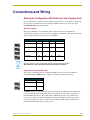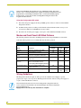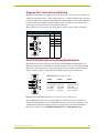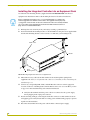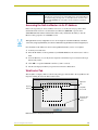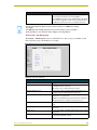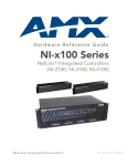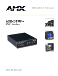
1
instruction manual
NetLinx Integrated
Controllers
(NI-2000, NI-3000, and NI-4000)
N e t L i n x C e n t ra l C o n t r o l l e r s a n d C a r d s
AMX Limited Warranty and Disclaimer
AMX Corporation warrants its products to be free of defects in material and workmanship under normal use for three
(3) years from the date of purchase from AMX Corporation, with the following exceptions:
•
Electroluminescent and LCD Control Panels are warranted for three (3) years, except for the display and touch
overlay components that are warranted for a period of one (1) year.
•
Disk drive mechanisms, pan/tilt heads, power supplies, and MX Series products are warranted for a period of one
(1) year.
•
AMX Lighting products are guaranteed to switch on and off any load that is properly connected to our lighting
products, as long as the AMX Lighting products are under warranty. AMX Corporation does guarantee the
control of dimmable loads that are properly connected to our lighting products. The dimming performance or
quality cannot be guaranteed due to the random combinations of dimmers, lamps and ballasts or transformers.
•
Unless otherwise specified, OEM and custom products are warranted for a period of one (1) year.
•
AMX Software is warranted for a period of ninety (90) days.
•
Batteries and incandescent lamps are not covered under the warranty.
This warranty extends only to products purchased directly from AMX Corporation or an Authorized AMX Dealer.
All products returned to AMX require a Return Material Authorization (RMA) number. The RMA number is
obtained from the AMX RMA Department. The RMA number must be clearly marked on the outside of each box.
The RMA is valid for a 30-day period. After the 30-day period the RMA will be cancelled. Any shipments received
not consistent with the RMA, or after the RMA is cancelled, will be refused. AMX is not responsible for products
returned without a valid RMA number.
AMX Corporation is not liable for any damages caused by its products or for the failure of its products to perform.
This includes any lost profits, lost savings, incidental damages, or consequential damages. AMX Corporation is not
liable for any claim made by a third party or by an AMX Dealer for a third party.
This limitation of liability applies whether damages are sought, or a claim is made, under this warranty or as a tort
claim (including negligence and strict product liability), a contract claim, or any other claim. This limitation of
liability cannot be waived or amended by any person. This limitation of liability will be effective even if AMX Corporation or an authorized representative of AMX Corporation has been advised of the possibility of any such damages.
This limitation of liability, however, will not apply to claims for personal injury.
Some states do not allow a limitation of how long an implied warranty last. Some states do not allow the limitation or
exclusion of incidental or consequential damages for consumer products. In such states, the limitation or exclusion of
the Limited Warranty may not apply. This Limited Warranty gives the owner specific legal rights. The owner may
also have other rights that vary from state to state. The owner is advised to consult applicable state laws for full
determination of rights.
EXCEPT AS EXPRESSLY SET FORTH IN THIS WARRANTY, AMX CORPORATION MAKES NO
OTHER WARRANTIES, EXPRESSED OR IMPLIED, INCLUDING ANY IMPLIED WARRANTIES OF
MERCHANTABILITY OR FITNESS FOR A PARTICULAR PURPOSE. AMX CORPORATION
EXPRESSLY DISCLAIMS ALL WARRANTIES NOT STATED IN THIS LIMITED WARRANTY. ANY
IMPLIED WARRANTIES THAT MAY BE IMPOSED BY LAW ARE LIMITED TO THE TERMS OF THIS
LIMITED WARRANTY.
This product includes the GoAhead Web Server.
Copyright (c) 2003 GoAhead Software, Inc. All Rights Reserved.
This product includes software developed by the OpenSSL Project for use in the OpenSSL Toolkit.
(http://www.openssl.org/)
This product includes cryptographic software written by Eric Young ([email protected])
Table of Contents
Table of Contents
Introduction ...............................................................................................................1
NI-2000 Specifications ...................................................................................................... 1
NI-3000 Specifications ...................................................................................................... 5
NI-4000 Specifications .................................................................................................... 10
Quick Setup and Configuration Overview ............................................................15
Installation Procedures.................................................................................................... 15
Configuration and Communication .................................................................................. 15
Update the Controller and Control Card Firmware.......................................................... 16
Program NetLinx Security into the On-Board Master ...................................................... 16
Connections and Wiring ........................................................................................17
Setting the Configuration DIP Switch (for the Program Port) .......................................... 17
Baud rate settings .................................................................................................................. 17
Program Run Disable (PRD) mode........................................................................................ 17
Using the Configuration DIP switch........................................................................................ 18
Modes and Front Panel LED Blink Patterns.................................................................... 18
Wiring Guidelines ............................................................................................................ 18
Preparing captive wires.......................................................................................................... 19
Wiring length guidelines ......................................................................................................... 19
Wiring a power connection..................................................................................................... 19
Using the 4-pin mini-Phoenix connector for data and power ................................................. 20
Using the 4-pin mini-Phoenix connector for data with external power ................................... 20
Program Port Connections and Wiring............................................................................ 21
RS-232/422/485 Device Port Wiring Specifications ........................................................ 21
ICSNet RJ-45 Connections/Wiring .................................................................................. 22
ICSHub OUT port................................................................................................................... 23
Ethernet 10/100 Base-T RJ-45 Connections/Wiring ....................................................... 23
Ethernet ports used by the Integrated Controllers ................................................................. 24
Relay Connections and Wiring ........................................................................................ 24
Relay connections.................................................................................................................. 25
Input/Output (I/O) Connections and Wiring ..................................................................... 25
IR/Serial Connections and Wiring ................................................................................... 26
NetLinx Control Card Slot Connector (NI-4000 unit only) ............................................... 27
NetLinx Integrated Controllers
i
Table of Contents
Installation and Upgrading .................................................................................... 29
Installing NetLinx Control Cards (NI-4000 Only) ............................................................. 29
Setting the NetLinx Control Card Addresses (NI-4000 Only).......................................... 30
Device:Port:System (D:P:S)............................................................................................ 30
Removing NetLinx Control Cards (NI-4000 Only) ........................................................... 31
Compact Flash Upgrades ............................................................................................... 31
Accessing the internal components on an Integrated Controller............................................ 31
Installation of Compact Flash upgrades................................................................................. 32
Closing and Securing the Integrated Controller ..................................................................... 33
Installing the Integrated Controller into an Equipment Rack ........................................... 34
Configuration and Firmware Update .................................................................... 37
Communicating with the Master via the Program Port.................................................... 37
Setting the System Value................................................................................................ 38
Using multiple NetLinx Masters.............................................................................................. 39
Changing the Device Address on a NetLinx Device ....................................................... 40
Recommended NetLinx Device numbers............................................................................... 41
Resetting the Factory Default System and Device Values.............................................. 41
Obtaining the Master’s IP Address (using DHCP) .......................................................... 42
Assigning a Static IP to the NetLinx Master .................................................................... 43
Communicating with the On-board Master via an IP....................................................... 44
Verifying the current version of NetLinx Master Firmware .............................................. 46
Upgrading the On-board Master Firmware via an IP ...................................................... 46
Upgrading the NI Controller Firmware via an IP ............................................................. 48
Upgrading the new NI Controller firmware via an IP .............................................................. 49
Upgrading the Control Card Firmware via an IP ............................................................. 51
NetLinx Security and Web Server ......................................................................... 53
NetLinx Security web browser and feature support ............................................................... 53
New Master Firmware Security Features........................................................................ 54
NetLinx Security Terms................................................................................................... 54
Accessing the NetLinx Master via its IP Address............................................................ 55
WebControl Tab .............................................................................................................. 55
Default Security Configuration ........................................................................................ 56
Security Tab .................................................................................................................... 57
Security tab - Enable Security page....................................................................................... 58
Security tab - Add Group page............................................................................................... 59
Security tab - Modify Group page .......................................................................................... 60
Security tab - Group Directory Associations page ................................................................. 61
Security tab - Add User page ................................................................................................. 63
ii
NetLinx Integrated Controllers
Table of Contents
Security tab - Modify User page............................................................................................. 64
Security tab - User Directory Associations page.................................................................... 65
Security tab - SSL Server Certificate page ............................................................................ 67
Security tab - Export Certificate Request page ...................................................................... 69
Security tab - Import Certificate page..................................................................................... 69
System Tab ..................................................................................................................... 70
Show Devices Tab .......................................................................................................... 70
Network Tab .................................................................................................................... 70
Master Security Setup Procedures.................................................................................. 71
Setting the system security options for a NetLinx Master (Security Options Menu) .............. 71
Adding a Group and assigning their access rights................................................................. 72
Modifying an existing Group’s access rights .......................................................................... 73
Showing a list of authorized Groups ...................................................................................... 74
Deleting an existing Group..................................................................................................... 74
Adding a Group directory association .................................................................................... 75
Confirming the new directory association .............................................................................. 76
Deleting a directory association ............................................................................................. 76
Adding a User and configuring their access rights................................................................. 77
Modifying an existing User’s access rights ............................................................................ 78
Showing a list of authorized Users......................................................................................... 79
Deleting a User ...................................................................................................................... 79
Adding a User directory association....................................................................................... 80
Confirming the new directory association .............................................................................. 81
Deleting a directory association ............................................................................................. 81
SSL Certificate Procedures ............................................................................................. 81
Self-Generating a SSL Server Certificate Request ................................................................ 82
Creating a Request for a SSL Server Certificate ................................................................... 83
Importing a CA certificate to the Master over a secure SSL connection................................ 84
Display SSL Server Certificate Information............................................................................ 85
Regenerating an SSL Server Certificate Request.................................................................. 85
Common Steps for Requesting a Certificate from a CA.................................................. 86
Accessing an SSL-Enabled Master via an IP Address.................................................... 88
Using your NetLinx Master to control the G4 panel ............................................................... 90
Using your NetLinx Master to control the G3 panel ............................................................... 91
What to do when a Certificate Expires ............................................................................ 92
NetLinx Security with a Terminal Connection .....................................................93
NetLinx Security Features ............................................................................................... 93
Initial Setup via a Terminal Connection........................................................................... 93
Establishing a Terminal connection ....................................................................................... 93
NetLinx Integrated Controllers
iii
Table of Contents
Accessing the Security configuration options.................................................................. 94
Option 1 - Set system security options for NetLinx Master (Security Options Menu) ............ 95
Option 2 - Display system security options for NetLinx Master.............................................. 96
Option 3 - Add user ................................................................................................................ 96
Option 4 - Edit User................................................................................................................ 97
Option 5 - Delete user ............................................................................................................ 99
Option 6 - Show the list of authorized users .......................................................................... 99
Option 7 - Add Group ............................................................................................................. 99
Option 8 - Edit Group ........................................................................................................... 102
Option 9 - Delete Group ....................................................................................................... 102
Option 10 - Show List of Authorized Groups........................................................................ 103
Option 11 - Set Telnet Timeout in seconds.......................................................................... 103
Option 12 - Display Telnet Timeout in seconds ................................................................... 103
Option 13 - Make changes permanent by saving to flash .................................................... 103
Main Security Menu ...................................................................................................... 104
Default Security Configuration ...................................................................................... 105
Help menu............................................................................................................................ 106
Logging Into a Session.................................................................................................. 107
Logout ........................................................................................................................... 108
Help Security........................................................................................................................ 108
Setup Security...................................................................................................................... 108
Programming ........................................................................................................ 109
Converting Axcess Code to NetLinx Code.................................................................... 109
Using the ID Button ....................................................................................................... 109
Device:Port:System (D:P:S)................................................................................................. 109
Program Port Commands ............................................................................................. 110
ESC Pass Codes .......................................................................................................... 113
Notes on Specific Telnet/Terminal Clients .................................................................... 113
WindowsTM client programs................................................................................................ 113
Linux Telnet client ................................................................................................................ 114
LED Disable/Enable Send_Commands ........................................................................ 114
RS-232/422/485 Send_Commands .............................................................................. 114
RS-232/422/485 Send_String Escape Sequences ....................................................... 117
IR / Serial Ports Channels............................................................................................. 118
IR RX Port Channels..................................................................................................... 118
IR/Serial Send_Commands........................................................................................... 118
Input/Output Send_Commands..................................................................................... 123
Troubleshooting ................................................................................................... 125
iv
NetLinx Integrated Controllers
Introduction
Introduction
NetLinx Integrated Master Controllers can be programmed to control RS-232/422/485, Relay, IR/
Serial, and Input/Output devices through the use of both the NetLinx programming language and
the NetLinx Studio application (version 2.2 or higher). Another key feature of this products is the
ability to easily access the configuration switches without having to remove a
cover plate.
NetLinx Integrated Master Controller Features
NI-2000
(FG2105-01)
• 1 RS-232 Program port
• 3 RS-232/RS-422/RS-485 ports
• 4 IR/Serial Output ports
• 4 Digital Input/Output ports
• 4 Relays
NI-3000
(FG2105-02)
• 1 RS-232 Program port
• 7 RS-232/RS-422/RS-485 ports
• 8 IR/Serial Output ports
• 8 Digital Input/Output ports
• 8 Relays
NI-4000
(FG2105)
• Support for up to 4 NetLinx control cards (such as NXC-COM2, NXC-IRS4, etc.)
• 1 RS-232 Program port
• 7 RS-232/RS-422/RS-485 ports
• 8 IR/Serial Output ports
• 8 Digital Input/Output ports
• 8 Relays
The NI series of controllers use a combination lithium battery and clock crystal package called a
Timekeeper. Only one Timekeeper unit is installed within a given NI controller. The battery can be
expected to have up to 3 years of usable life under very adverse conditions. Actual life is
appreciably longer under normal operating conditions. This calculation is based on storing the unit
without power in 50° C (120° F) temperature until battery levels are no longer acceptable. The part
number for a replacement battery is 57-0032.
NI-2000 Specifications
The front panel LEDs (FIG. 1) are grouped by control type and are numbered according to their
corresponding port (connector) numbers on the rear of the unit. The back of the unit contains
three RS-232/422/485, one Relay, one IR/Serial and one I/O connectors. In addition, this unit
provides an ID pushbutton, AXlink LED, and other related connectors. FIG. 2 shows the front and
rear of the NI-2000.
NetLinx Integrated Controllers
1
Introduction
FIG. 1 NI-2000 NetLinx Integrated Controller (front view)
RS-232/422/485 TX/RX LEDs (red/yellow)
Link/Active-Status-Output-Input
Relay LEDs (red)
IR/Serial LEDs (red)
I/O LEDs
(yellow)
Front
ICSNet (2)
Rear
RS-232/422/485 (Ports 1-3)
Relays
(Port 4)
ICSHub Out
Ethernet
IR/Serial (Ports 5-8)
I/O (Port 9)
DIP
switch
Program
port
AXLink LED
(green)
AXLink
port
PWR
ID Pushbutton
FIG. 2 NI-2000 front and rear panel components
NI-2000 Specifications
Dimensions (HWD):
• 3.47" x 17.00" x 3.47" (8.81 cm x 43.18 cm x 8.82 cm)
• 2 RU (rack unit) high
Power requirements:
• 700 mA @ 12 VDC
Memory:
• 32 MB SDRAM
• 1 MB of Non-volatile Flash
2
Compact Flash:
• 32 MB Card (upgradeable). Refer to the Optional Accessories section on
page 5 for more information.
Weight:
• 4.50 lbs (2.04 kg)
Enclosure:
• Metal with black matte finish
NetLinx Integrated Controllers
Introduction
NI-2000 Specifications (Cont.)
Front Panel Components:
LINK/ACT
• Green LED lights when the Ethernet cable is connected and an active link
is established. This LED also blinks when receiving Ethernet data packets.
Status
• Green LED lights to indicate that the system is programmed and
communicating properly.
Output
• Red LED lights when the Controller transmits data, sets channels On/Off,
sends data strings, etc.
Input
• Yellow LED blinks when the Controller receives data from button pushes,
strings, commands, channel levels, etc.
RS-232/422/485 LEDs
• Three sets of red and yellow LEDs light to indicate the rear DB9 Ports 1-3
are transmitting or receiving RS-232, 422, or 485 data:
- TX LEDs (red) light when transmitting data
- RX LEDs (yellow) light when receiving data
- LED activity reflects transmission and reception activity
Relay LEDs
• Four red LEDs light to indicate the rear relay channels 1-4 are active
(closed).
• These LEDs reflect the state of the relay on Port 4
• If the relay is engaged = LED On and if the relay is Off = LED Off
IR/Serial LEDs
• Four red LEDs light to indicate the rear IR/Serial channels 1-4 are
transmitting control data on Ports 5-8
• LED indictor for each IR port remains lit for the length of time that IR/Serial
data is being generated
I/O LEDs
• Four yellow LEDs light when the rear I/O channels 1-4 are active
• LED indicator for each I/O port reflects the state of that particular port
Rack-mount brackets
• Provide an installation option for the Integrated Controller to be mounted
into an equipment rack.
Rear Panel Components:
RS-232/422/485 (Ports 1 -3)
• Three RS-232/422/485 control ports using DB9 (male) connectors with
XON/XOFF (transmit On/transmit Off), CTS/RTS (clear to send/ready to
send), and 300-115,200 baud.
• Channel range = 1-255
• Channels 1-254 provide feedback
• Channel 255 (CTS Push channel): Reflects the state of the CTS Input if a
'CTSPSH' command was sent to the port
• Output data format for each port is selected via software
• Three DB9 connectors provide RS-232/422/485 termination
ICSNet
• Two RJ-45 connectors for ICSNet interface
ICSHub Out
• Single RJ-45 connector provides data to another Hub connected to the
Controller
Relay (Port 4)
• Four-channel single-pole single-throw relay ports
• Each relay is independently controlled.
• Supports up to 4 independent external relay devices
• Channel range = 1-4
• Each relay can switch up to 24 VDC or 28 VAC @ 1 A
• One 8-pin 3.5 mm mini-Phoenix (female) connector provides relay
termination
NetLinx Integrated Controllers
3
Introduction
NI-2000 Specifications (Cont.)
Digital I/O (Port 9)
• Four-channel binary I/O port for contact closure
• Each input is capable of voltage sensing. Input format is software
selectable.
• Interactive power sensing for IR ports
• Channel range = 1-4
• All inputs are assigned to respective IR/Serial ports for "automatic" power
control through the use of software commands. Power control is provided
via commands such as: ’PON’, ’POF’, ’POD’, ’DELAY’, I/O Link etc.).
• Contact closure between GND and an I/O port is detected as a PUSH
• When used as voltage input - I/O port detects a low signal (0- 1.5 VDC) as
a PUSH and a high signal (3.5 - 5 VDC) as a RELEASE
• When used as an output - each I/O port acts as a switch to GND and is
rated at 200 mA @ 12 VDC
• One 6-pin 3.5 mm mini-Phoenix (female) connector provides I/O port
termination
IR/Serial (Ports 5-8)
• Four IR/Serial control ports support high-frequency carriers up to
1.142 MHz
• Each output is capable of two electrical formats: IR or Serial
• Four IR/Serial data signals can be generated simultaneously.
• Channel range = 1-32,767
• Channels 1-128 (output): IR commands
• Channels 129-253: used as reference channels
• Channel 254 (feedback): Power Fail (used with 'PON' and 'POF'
commands)
• Channel 255 (feedback): Power status (when IO Link is set)
• One 8-pin 3.5 mm mini-Phoenix (female) connector provides IR/Serial port
termination
IR/Serial (Ports 5-8)
• Four IR/Serial control ports support high-frequency carriers up to 1.142
MHz
• Each output is capable of two electrical formats: IR or Serial
• Four IR/Serial data signals can be generated simultaneously
• Channel range = 1-32,767
• Channels 1-128 (output): IR commands
• Channels 129-253: used as reference channels
• Channel 254 (feedback): Power Fail (used with 'PON' and 'POF'
commands)
• Channel 255 (feedback): Power status (when IO Link is set)
• One 8-pin 3.5 mm mini-Phoenix (female) connector provides IR/Serial port
termination
Program port
• Single RS-232 DB9 connector (male) can be connected to a DB9 port on a
computer; used with serial commands, NetLinx programming commands,
other DB9 capable devices, and to upload/download information from the
NetLinx Studio 2.2 program.
Configuration DIP switch
• Use this DIP switch to set the communication parameters for the rear
RS232 Program port.
ID pushbutton
• Sets the NetLinx ID (D) assignment for the device.
• The D notation is used to explicitly represent a device number.
Ethernet port
4
• Single RJ-45 port for 10/100 Mbps communication. The Ethernet Port
automatically negotiates the connection speed (10 Mbps or 100 Mbps) and
whether to use half duplex or full duplex mode.
NetLinx Integrated Controllers
Introduction
NI-2000 Specifications (Cont.)
Ethernet Link/Activity LED
• LEDs show communication activity, connections, speeds, and mode
information:
SPD-speed - Yellow LED lights On when the connection speed is 100 Mbps
and turns Off when the speed is 10 Mbps.
L/A-link/activity - Green LED lights On when the Ethernet cables are
connected/terminated correctly and blinks when receiving Ethernet data
packets.
AXlink LED
• One green LED indicates the state of the AXlink connector port.
• Normal AXlink activity = 1 blink/second
• Abnormal AXLink activity = cycle of 3 consecutive blinks and then Off
AXlink port
• 4-pin 3.5 mm mini-Phoenix (male) connector provides data and power to
external control devices.
Power port
• 2-pin 3.5 mm mini-Phoenix (male) connector
Included Accessories:
• 2 CC-NIRC IR Emitters (FG10-000-11)
• Installation Kit (KA2105-01):
One 8-pin Relay Common Strip (41-2105-01)
Four rack mount screws (80-0186)
Four washers (80-0342)
• One 8-pin 3.5 mm mini-Phoenix (female) Relay connector (41-5083)
• One 6-pin 3.5 mm mini-Phoenix (female) I/O connector (41-5063)
• One 4-pin 3.5 mm mini-Phoenix (female) AXlink connector (41-5047)
• One 2-pin 3.5 mm mini-Phoenix (female) PWR connector (41-5025)
• Removable rack ears. Allows for tabletop and under-counter mountings
Optional Accessories:
• 2 Pin Black Male Phoenix Connector (3.5mm) (41-5026)
• CC-NIRC IR cables (FG10-000-11)
• CC-NSER IR/Serial cables (FG10-007-10)
• CSB Cable Support Bracket (FG517)
• NCK, NetLinx Connector Kit (FG2902)
• NI-2000 Quick Start Guide (93-2105-01)
• PSN2.8 12 VDC power supply (FG423-17)
• PSN6.5 12 VDC power supply (FG423-41)
• STS, Serial To Screw Terminal (FG959)
• Upgrade Compact Flash (factory programmed with firmware):
NXA-CFNI64M - 64 MB compact flash card (FG2116-31)
NXA-CFNI128M - 128 MB compact flash card (FG2116-32)
NXA-CFNI256M - 256 MB compact flash card (FG2116-33)
NXA-CFNI512M - 512 MB compact flash card (FG2116-34)
NXA-CFNI1G - 1 GB compact flash card (FG2116-35)
NI-3000 Specifications
The front LEDs (FIG. 3) are grouped by control type and are numbered according to their
corresponding port (connector) numbers on the rear of the unit. The back of the this unit contains
RS-232/422/485, Relay, IR/Serial and I/O connectors. In addition, this unit provides an ID
pushbutton, AXlink LED, and other related connectors. FIG. 4 shows the front and rear of the
NI-3000.
NetLinx Integrated Controllers
5
Introduction
FIG. 3 NI-3000 NetLinx Integrated Controller (front view)
RS-232/422/485 TX/RX LEDs (red/yellow)
Link/Active-Status-Output-Input
Relay LEDs (red)
IR/Serial LEDs (red)
I/O LEDs (yellow)
Front
ICSNet (2)
Rear
RS-232/422/485 (Ports 1-7)
Relays
(Port 8)
ICSHub Out
IR/Serial (Ports 9-16)
I/O (Port 17)
Program
port
DIP
switch
Ethernet
AXLink LED
(green)
AXLink
port
PWR
ID Pushbutton
FIG. 4 NI-3000 front and rear panel components
6
NetLinx Integrated Controllers
Introduction
NI-3000 Specifications (Cont.)
Dimensions (HWD):
• 3.47" x 17.00" x 3.47" (8.81 cm x 43.18 cm x 8.82 cm)
• 2 RU (rack unit) high
Power requirements:
• 900 mA @ 12 VDC
Memory:
• 32 MB SDRAM
• 1 MB of Non-volatile Flash
Compact Flash:
• 32 MB Card (upgradeable). Refer to the Optional Accessories section on
page 10 for more information.
Weight:
• 4.55 lbs (2.06 kg)
Enclosure:
• Metal with black matte finish
Front Panel Components:
LINK/ACT
• Green LED lights when the Ethernet cable is connected and an active link
is established. This LED also blinks when receiving Ethernet data packets.
Status
• Green LED lights to indicate that the system is programmed and
communicating properly.
Output
• Red LED lights when the Controller transmits data, sets channels On/Off,
sends data strings, etc.
Input
• Yellow LED lights when the Controller receives data from button pushes,
strings, commands, channel levels, etc.
RS-232/422/485 LEDs
• Seven sets of red and yellow LEDs light to indicate the rear DB9 Ports 1-7
are transmitting or receiving RS-232, 422, or 485 data:
- TX LEDs (red) light when transmitting data
- RX LEDs (yellow) light when receiving data
- LED activity reflects transmission and reception activity
Relay LEDs
• Eight red LEDs light to indicate the rear relay channels 1-8 are active
(closed)
• These LEDs reflect the state of the relay on Port 8
• If the relay is engaged = LED On and if the relay is Off = LED Off
IR/Serial LEDs
• Eight red LEDs light to indicate the rear IR/Serial channels 1-8 are
transmitting control data on Ports 9-16
• LED indictor for each IR port remains lit for the length of time that IR/Serial
data is being generated
I/O LEDs
• Eight yellow LEDs light when the rear I/O channels 1-8 are active
• LED indicator for each I/O port reflects the state of that particular port
Rack-mount brackets
NetLinx Integrated Controllers
• Provide an installation option for the Integrated Controller to be mounted
into an equipment rack.
7
Introduction
NI-3000 Specifications (Cont.)
Rear Panel Components:
RS-232/422/485 (Ports 1 -7)
• Seven RS-232/422/485 control ports using DB9 (male) connectors with
XON/XOFF (transmit on/transmit off), CTS/RTS (clear to send/ready to
send), and 300-115,200 baud.
• Channel range = 1-255
• Channels 1-254 provide feedback
• Channel 255 (CTS Push channel): Reflects the state of the CTS Input if a
'CTSPSH' command was sent to the port
• Output data format for each port is selected via software
• Seven DB9 connectors provide RS-232/422/485 termination
ICSNet
• Two RJ-45 connectors for ICSNet interface
ICSHub Out
• Single RJ-45 connector provides data to another Hub connected to the
Controller
Relay (Port 8)
• Eight-channel single-pole single-throw relay ports
• Each relay is independently controlled.
• Supports up to 8 independent external relay devices
• Channel range = 1-8
• Each relay can switch up to 24 VDC or 28 VAC @ 1 A
• Two 8-pin 3.5 mm mini-Phoenix (female) connectors provide relay
termination
Digital I/O (Port 17)
• Eight-channel binary I/O port for contact closure
• Each input is capable of voltage sensing. Input format is software
selectable.
• Interactive power sensing for IR ports
• Channel range = 1-8
• All inputs are assigned to respective IR/Serial ports for "automatic" power
control through the use of software commands. Power control is provided
via commands such as: ’PON’, ’POF’, ’POD’, ’DELAY’, I/O Link etc.).
• Contact closure between GND and an I/O port is detected as a PUSH
• When used as voltage input - I/O port detects a low signal (0- 1.5 VDC) as
a PUSH and a high signal (3.5 - 5 VDC) as a RELEASE
• When used as an output - each I/O port acts as a switch to GND and is
rated at 200 mA @ 12 VDC
• One 10-pin 3.5 mm mini-Phoenix (female) connector provides I/O port
termination
IR/Serial (Ports 9-16)
• Eight IR/Serial control ports support high-frequency carriers up to
1.142 MHz
• Each output is capable of two electrical formats: IR or Serial
• Eight IR/Serial data signals can be generated simultaneously.
• Channel range = 1-32,767
• Channels 1-128 (output): IR commands
• Channels 129-253: used as reference channels
• Channel 254 (feedback): Power Fail (used with 'PON' and 'POF'
commands)
• Channel 255 (feedback): Power status (when IO Link is set)
• Two 8-pin 3.5 mm mini-Phoenix (female) connectors provide IR/Serial port
termination
8
NetLinx Integrated Controllers
Introduction
NI-3000 Specifications (Cont.)
IR/Serial (Ports 9-16)
• Eight IR/Serial control ports support high-frequency carriers up to
1.142 MHz
• Each output is capable of two electrical formats: IR or Serial
• Eight IR/Serial data signals can be generated simultaneously
• Channel range = 1-32,767
• Channels 1-128 (output): IR commands
• Channels 129-253: used as reference channels
• Channel 254 (feedback): Power Fail (used with 'PON' and 'POF'
commands)
• Channel 255 (feedback): Power status (when IO Link is set)
• Two 8-pin 3.5 mm mini-Phoenix (female) connectors provide IR/Serial port
termination
Program port
• Single RS-232 DB9 connector (male) can be connected to a DB9 port on a
computer; used with serial commands, NetLinx programming commands,
other DB9 capable devices, and to upload/download information from the
NetLinx Studio 2.2 program.
Configuration DIP switch
• Use this DIP switch to set the communication parameters for the rear
RS232 Program port.
ID pushbutton
• Sets the NetLinx ID (D) assignment for the device.
Ethernet port
• Single RJ-45 port for 10/100 Mbps communication. The Ethernet Port
automatically negotiates the connection speed (10 Mbps or 100 Mbps) and
whether to use half duplex or full duplex mode.
Ethernet Link/Activity LED
• LEDs show communication activity, connections, speeds, and mode
information:
• The D notation is used to explicitly represent a device number.
SPD-speed - Yellow LED lights On when the connection speed is 100 Mbps
and turns Off when the speed is 10 Mbps.
L/A-link/activity - Green LED lights On when the Ethernet cables are
connected/terminated correctly and blinks when receiving Ethernet data
packets.
AXlink LED
• One green LED indicates the state of the AXlink connector port.
• Normal AXlink activity = 1 blink/second
• Abnormal AXLink activity = cycle of 3 consecutive blinks and then Off
AXlink port
• 4-pin 3.5 mm mini-Phoenix (male) connector provides data and power to
external control devices.
Power port
• 2-pin 3.5 mm mini-Phoenix (male) connector
Included Accessories:
• 4 CC-NIRC IR Emitters (FG10-000-11)
• One 10-pin 3.5 mm mini-Phoenix (female) I/O connector (41-5107)
• Two 8-pin 3.5 mm mini-Phoenix (female) Relay connector (41-5083)
• One 4-pin 3.5 mm mini-Phoenix (female) AXlink connector (41-5047)
• One 2-pin 3.5 mm mini-Phoenix (female) PWR connector (41-5025)
• Installation Kit (KA2105-01):
One 8-pin Relay Common Strip (41-2105-01)
Four rack mount screws (80-0186)
Four washers (80-0342)
• Removable rack ears. Allows for tabletop and under-counter mountings
NetLinx Integrated Controllers
9
Introduction
NI-3000 Specifications (Cont.)
Optional Accessories:
• 2 Pin Black Male Phoenix Connector (3.5mm) (41-5026)
• CC-NIRC IR cables (FG10-000-11)
• CC-NSER IR/Serial cables (FG10-007-10)
• CSB Cable Support Bracket (FG517)
• NCK, NetLinx Connector Kit (FG2902)
• NI-3000 Quick Start Guide (93-2105-01)
• PSN2.8 12 VDC power supply (FG423-17)
• PSN6.5 12 VDC power supply (FG423-41)
• STS, Serial To Screw Terminal (FG959)
• Upgrade Compact Flash (factory programmed with firmware):
NXA-CFNI64M - 64 MB compact flash card (FG2116-31)
NXA-CFNI128M - 128 MB compact flash card (FG2116-32)
NXA-CFNI256M - 256 MB compact flash card (FG2116-33)
NXA-CFNI512M - 512 MB compact flash card (FG2116-34)
NXA-CFNI1G - 1 GB compact flash card (FG2116-35)
NI-4000 Specifications
The front LEDs (FIG. 5) are grouped by control type, and are numbered according to their
corresponding port (connector) numbers on the rear of the unit. The back of the this unit contains
RS-232/422/485, Relay, IR/Serial and I/O connectors. In addition, this unit provides an ID
pushbutton, AXlink LED, NetLinx Card slots, and other related connectors. FIG. 6 shows the front
and rear of the NI-4000.
FIG. 5 NI-4000 NetLinx Integrated Controller (front view)
10
NetLinx Integrated Controllers
Introduction
RS-232/422/485 TX/RX LEDs (red/yellow)
Relay LEDs (red)
IR/Serial LEDs (red)
Link/Active-Status-Output-Input
NetLinx
Card
slots
(1-4)
I/O LEDs (yellow)
Front
RS-232/422/485 (Ports 1-7)
Rear
Relays
(Port 8)
I/O (Port 17)
ICSNet (2)
ICSHub Out
IR/Serial (Ports 9-16)
AXLink LED
(green)
AXLink
port
Ethernet
DIP
switch
Program port
PWR
CardFrame DIP
switch
Slot 1-4 connectors
ID Pushbutton
FIG. 6 NI-4000 front and rear panel components
NI-4000 Specifications
Dimensions (HWD):
• 5.21" x 17.00" x 9.60" (13.23 cm x 43.18 cm x 24.27 cm)
• 3 RU (rack unit) high
Power requirements:
• 900 mA @ 12 VDC (no cards)
Memory:
• 32 MB SDRAM
• 1 MB of Non-volatile Flash
Compact Flash:
• 32 MB Card (upgradeable). Refer to the Optional Accessories section on
page 14 for more information.
Weight:
• 9.15 lbs (4.15 kg)
Enclosure:
• Metal with black matte finish
Front Panel Components:
LINK/ACT
• Green LED lights when the Ethernet cable is connected and an active link
is established. This LED also blinks when receiving Ethernet data packets.
Status
• Green LED lights to indicate that the system is programmed and
communicating properly.
Output
• Red LED lights when the Controller transmits data, sets channels On/Off,
sends data strings, etc.
Input
• Yellow LED lights when the Controller receives data from button pushes,
strings, commands, channel levels, etc.
RS-232/422/485 LEDs
• Seven sets of red and yellow LEDs light to indicate the rear DB9 Ports 1-7
are transmitting or receiving RS-232, 422, or 485 data:
- TX LEDs (red) light when transmitting data
- RX LEDs (yellow) light when receiving data
- LED activity reflects transmission and reception activity
NetLinx Integrated Controllers
11
Introduction
NI-4000 Specifications (Cont.)
Relay LEDs
• Eight red LEDs light to indicate the rear relay channels 1-8 are active
(closed)
• These LEDs reflect the state of the relay on Port 8
• If the relay is engaged = LED On and if the relay is Off = LED Off
IR/Serial LEDs
• Eight red LEDs light to indicate the rear IR/Serial channels 1-8 are
transmitting control data on Ports 9-16
• LED indictor for each IR port remains lit for the length of time that IR/Serial
data is being generated
I/O LEDs
• Eight yellow LEDs light when the rear I/O channels 1-8 are active
• LED indicator for each I/O port reflects the state of that particular port
NetLinx Control
Card slots 1- 4
Accepts up to 4 compatible NetLinx Control Cards:
• NXC-COM2 Dual COM Port Control Card (FG2022)
• NXC-I/O10 Input/Output Control Card (FG2021)
• NXC-IRS4 4-Port IR/S Control Card (FG2023)
• NXC-REL10 Relay Control Card (FG2020)
• NXC-VAI4 Analog Voltage Control Card (FG 2025)
• NXC-VOL4 Volume Control Card (FG2024)
Rack-mount brackets
• Provide an installation option for the Integrated Controller to be mounted
into an equipment rack.
Rear Panel Components:
RS-232/422/485 (Ports 1 -7)
• Seven RS-232/422/485 control ports using DB9 (male) connectors with
XON/XOFF (transmit on/transmit off), CTS/RTS (clear to send/ready to
send), and 300-115,200 baud.
• Channel range = 1-255
• Channels 1-254 provide feedback
• Channel 255 (CTS Push channel): Reflects the state of the CTS Input if a
'CTSPSH' command was sent to the port
• Output data format for each port is selected via software
• Seven DB9 connectors provide RS-232/422/485 termination
ICSNet
• Two RJ-45 connectors for ICSNet interface
ICSHub Out
• Single RJ-45 connector provides data to another Hub connected to the
Controller
Relay (Port 8)
• Eight-channel single-pole single throw relay ports
• Each relay is independently controlled.
• Supports up to 8 independent external relay devices
• Channel range = 1-8
• Each relay can switch up to 24 VDC or 28 VAC @ 1 A
• Two 8-pin 3.5 mm mini-Phoenix (female) connectors provide relay
termination
12
NetLinx Integrated Controllers
Introduction
NI-4000 Specifications (Cont.)
Digital I/O (Port 17)
• Eight-channel binary I/O port for contact closure
• Each input is capable of voltage sensing. Input format is software
selectable.
• Interactive power sensing for IR ports
• Channel range = 1-8
• All inputs are assigned to respective IR/Serial ports for "automatic" power
control through the use of software commands. Power control is provided
via commands such as: ’PON’, ’POF’, ’POD’, ’DELAY’, I/O Link etc.).
• Contact closure between GND and an I/O port is detected as a PUSH
• When used as voltage input - I/O port detects a low signal (0- 1.5 VDC) as
a PUSH and a high signal (3.5 - 5 VDC) as a RELEASE
• When used as an output - each I/O port acts as a switch to GND and is
rated at 200 mA @ 12 VDC
• One 10-pin 3.5 mm mini-Phoenix (female) connector provides I/O port
termination
IR/Serial (Ports 9-16)
• Eight IR/Serial control ports support high-frequency carriers up to
1.142 MHz
• Each output is capable of two electrical formats: IR or Serial
• Eight IR/Serial data signals can be generated simultaneously.
• Channel range = 1-32,767
• Channels 1-128 (output): IR commands
• Channels 129-253: used as reference channels
• Channel 254 (feedback): Power Fail (used with 'PON' and 'POF'
commands)
• Channel 255 (feedback): Power status (when IO Link is set)
• Two 8-pin 3.5 mm mini-Phoenix (female) connectors provide IR/Serial port
termination
Program port
• Single RS-232 DB9 connector (male) can be connected to a DB9 port on a
computer; used with serial commands, NetLinx programming commands,
other DB9 capable devices, and to upload/download information from the
NetLinx Studio 2.2 program.
Configuration DIP switch
• Use this DIP switch to set the communication parameters for the rear
RS232 Program port.
ID pushbutton
• Sets the NetLinx ID (D) assignment for the device.
• The D notation is used to explicitly represent a device number.
Ethernet port
• Single RJ-45 port for 10/100 Mbps communication. The Ethernet Port
automatically negotiates the connection speed (10 Mbps or 100 Mbps) and
whether to use half duplex or full duplex mode.
Ethernet Link/Activity LED
• LEDs show communication activity, connections, speeds, and mode
information:
SPD-speed - Yellow LED lights On when the connection speed is 100 Mbps
and turns Off when the speed is 10 Mbps.
L/A-link/activity - Green LED lights On when the Ethernet cables are
connected/terminated correctly and blinks when receiving Ethernet data
packets.
AXlink LED
• One green LED indicates the state of the AXlink connector port.
• Normal AXlink activity = 1 blink/second
• Abnormal AXLink activity = cycle of 3 consecutive blinks and then Off
AXlink port
• 4-pin 3.5 mm mini-Phoenix (male) connector provides data and power to
external control devices.
Power port
• 2-pin 3.5 mm mini-Phoenix (male) connector
NetLinx Integrated Controllers
13
Introduction
NI-4000 Specifications (Cont.)
CardFrame Number
DIP switch
• Sets the starting address for the Control Cards in the CardFrame.(Factory
default CardFrame DIP switch value = 0).
• The Control Card address range is 1-3064.
NetLinx Control Card
connectors (1-4)
Included Accessories:
• Four 20-pin (male) connectors that bridge the gap between the Control
Cards in the CardFrame and external equipment.
• Two CC-NIRC IR Emitters (FG10-000-11)
• One 10-pin 3.5 mm mini-Phoenix (female) I/O connector (41-5107)
• Two 8-pin 3.5 mm mini-Phoenix (female) Relay connector (41-5083)
• One 4-pin 3.5 mm mini-Phoenix (female) AXlink connector (41-5047)
• One 2-pin 3.5 mm mini-Phoenix (female) PWR connector (41-5025)
• Installation Kit (KA2105-01):
One 8-pin Relay Common Strip (41-2105-01)
Four rack mount screws (80-0186)
Four washers (80-0342)
• Removable rack ears. Allows for tabletop, under-counter, and
front/rear rack mounting
Optional Accessories:
• 2 Pin Black Male Phoenix Connector (3.5mm) (41-5026)
• CC-NIRC IR cables (FG10-000-11)
• CC-NSER IR/Serial cables (FG10-007-10)
• CSB Cable Support Bracket (FG517)
• NCK, NetLinx Connector Kit (FG2902)
• NI-4000 Quick Start Guide (93-2105-01)
• PSN2.8 12 VDC power supply (FG423-17)
• PSN6.5 12 VDC power supply (FG423-41)
• STS, Serial To Screw Terminal (FG959)
• Upgrade Compact Flash (factory programmed with firmware):
NXA-CFNI64M - 64 MB compact flash card (FG2116-31)
NXA-CFNI128M - 128 MB compact flash card (FG2116-32)
NXA-CFNI256M - 256 MB compact flash card (FG2116-33)
NXA-CFNI512M - 512 MB compact flash card (FG2116-34)
NXA-CFNI1G - 1 GB compact flash card (FG2116-35)
• NXC cards (see the Card Slot section (page 12) of this Specification table
for more detailed information)
14
NetLinx Integrated Controllers
Quick Setup and Configuration Overview
Quick Setup and Configuration Overview
Installation Procedures
These are the steps involved with the most common installation procedures of these devices:
Carefully unpack the contents of the box.
Confirm the contents of box (page 2 thru page 14).
Familiarize yourself with the units’ connectors and wiring configurations (Connections
and Wiring section on page 17).
Upgrade the factory default 32 MB memory module with a selection of memory sizes
ranging from 64 MB to 1 GB (Compact Flash Upgrades section on page 31), if
necessary.
Install any optional NXC Control Cards (Installing NetLinx Control Cards (NI-4000
Only) section on page 29).
Set the Control Card Address range (Setting the NetLinx Control Card Addresses (NI4000 Only) section on page 30) and a Device value (Device:Port:System (D:P:S) section
on page 30).
Set the communication speed on the Program Port DIP switch (Setting the Configuration
DIP Switch (for the Program Port) section on page 17). Default is 38400.
Connect all rear panel components and supply power to the NI unit from the optional
PSN power supply.
Configuration and Communication
These are the general steps involved with setting up and communicating with the Integrated
Controllers’ on-board Master. In the initial communication process:
Connect and communicate with the on-board Master by using the Program port
(Communicating with the Master via the Program Port section on page 37).
Setup the System Value being used with the on-board Master (Setting the System
Value section on page 38).
Re-assign any Device values (Changing the Device Address on a NetLinx Device section
on page 40).
You can then either get a DHCP address for the on-board Master (Obtaining the Master’s
IP Address (using DHCP) section on page 42) or assign a Static IP to the on-board
Master (Assigning a Static IP to the NetLinx Master section on page 43).
Once the IP information is determined, rework the parameters for Master Communication
in order to connect to the on-board Master via the Ethernet and not the Program port
(Communicating with the On-board Master via an IP section on page 44).
NetLinx Integrated Controllers
15
Quick Setup and Configuration Overview
Update the Controller and Control Card Firmware
Before using your new Integrated Controller, you must FIRST update your NetLinx
Studio to the most recent release.
Upgrade the on-board Master firmware through an IP Address via the Ethernet connector
(Upgrading the On-board Master Firmware via an IP section on page 46)
(IP recommended).
Upgrade any connected NetLinx Control Cards being used within the NI-4000 unit
through an IP Address (Upgrading the Control Card Firmware via an IP Address section
on page 52).
Once programming of the on-board Master is complete and the NetLinx Control Cards
are installed; you can now finalize the installation process.
This installation process is done by replacing the faceplate on the NI-4000 (Installing
NetLinx Control Cards (NI-4000 Only) section on page 29) and installing the Controller
into an equipment rack (Installing the Integrated Controller into an Equipment
Rack section on page 34).
Program NetLinx Security into the On-Board Master
Setup and finalize your NetLinx Security Protocols (NetLinx Security and Web
Server section on page 53 or NetLinx Security with a Terminal Connection section on
page 93).
Program your NI Controller (Programming section on page 109).
16
NetLinx Integrated Controllers
Connections and Wiring
Connections and Wiring
Setting the Configuration DIP Switch (for the Program Port)
Prior to installing the Controller, use the Configuration DIP switch to set the baud rate used by the
Program port for communication. The Configuration DIP switch is located on the rear of the
NI-4000/3000/2000 Integrated Controllers.
Baud rate settings
Before programming the on-board Master, make sure the baud rate you set matches the
communication parameters set on both your PC’s COM port or and those set through your NetLinx
Studio 2.2. By default, the baud rate is set to 38,400 (bps).
Baud Rate Settings on the Configuration DIP Switch
Baud Rate
Position 5 Position 6 Position 7
Position 8
9600 bps
OFF
ON
OFF
ON
38,400 bps (default)
OFF
ON
ON
ON
57,600 bps
ON
OFF
OFF
OFF
115,200 bps
ON
ON
ON
ON
Note the orientation of the Configuration DIP Switch and the ON position label.
DIP switches 2,3, and 4 must remain in the OFF position at all times.
Program Run Disable (PRD) mode
You can also use the Program port’s Configuration DIP switch to set the on-board Master to
Program Run Disable (PRD) mode according to the settings listed in the table below.
PRD Mode Settings
PRD Mode
Position 1
Normal mode (default)
OFF
PRD Mode
ON
The PRD mode prevents the NetLinx program stored in the on-board Master from running when
you power up the Integrated Controller. This mode should only be used when you suspect the
resident NetLinx program is causing inadvertent communication and/or control problems. If
necessary, place the on-board Master in PRD mode and use the NetLinx Studio 2.2 program to
resolve the communication and/or control problems with the resident NetLinx program. Then
download the new NetLinx program and try again.
NetLinx Integrated Controllers
17
Connections and Wiring
Think of the PRD Mode (On) equating to a PC’s SAFE Mode setting. This mode
allows a user to continue powering a unit, update the firmware, and download a new
program while circumventing any problems with a currently downloaded program.
Power must be cycled to the unit after activating/deactivating this mode on the
Program Port DIP switch #1.
Using the Configuration DIP switch
1. Disconnect the power supply from the 2-pin PWR (green) connector on the rear of the NetLinx
Integrated Controller.
2. Set DIP switch positions according to the information listed in the Baud Rate Settings on the
Configuration DIP Switch and PRD Mode Settings tables.
3. Reconnect the 12 VDC power supply to the 2-pin 3.5 mm mini-Phoenix PWR connector.
Modes and Front Panel LED Blink Patterns
The following table lists the modes and blink patterns for the front panel LEDs associated with
each mode. These patterns are not evident until after the unit is powered.
Modes and LED Blink Patterns
LEDs and Blink Patterns
STATUS
(green)
OUTPUT
(red)
INPUT
(yellow)
On
Mode
Description
OS Start
Starting the operating system (OS).
On
On
Boot
On-board Master is booting.
On
Off
On
Contacting DHCP
server
On-board Master is contacting a DHCP
server for IP configuration information.
On
Off
Fast Blink
Unknown DHCP
server
On-board Master could not find the
DHCP server.
Fast Blink
Off
Off
Downloading Boot
firmware
Downloading Boot firmware to the
Master’s on-board flash memory.
Fast Blink
Fast Blink Fast Blink
Do not cycle power during this process!
No program running
There is no program loaded, or the
program is disabled.
Normal
On-board Master is functioning normally.
On
Normal
1 blink per second Indicates
activity
Normal
Indicates
activity
Wiring Guidelines
The Integrated Controllers require 12 VDC power from a NetLinx Power Supply to operate
properly (this supply is unit dependent). The Integrated Controller connects to the power supply via
a 2-pin 3.5 mm mini-Phoenix connector.
This unit should only have one source of incoming power. Using more than one
source of power to the Controller can result in damage to the internal components
and a possible burn out.
Apply power to the unit only after installation is complete.
18
NetLinx Integrated Controllers
Connections and Wiring
Preparing captive wires
You will need a wire stripper and flat-blade screwdriver to prepare and connect the captive wires.
Never pre-tin wires for compression-type connections.
1. Strip 0.25 inch (6.35 mm) of insulation off all wires.
2. Insert each wire into the appropriate opening on the connector (according to the wiring
diagrams and connector types described in this section).
3. Tighten the screws to secure the wire in the connector. Do not tighten the screws excessively,
doing so may strip the threads and damage the connector.
Wiring length guidelines
The NetLinx Integrated Controllers require auxiliary 12 VDC power from a PSN to operate
properly. The unit should only have one source of incoming power.
Refer to the following tables for the wiring length information used with the different types of
NetLinx Integrated Controllers:
Wiring Guidelines - NI-4000 & NI-3000@ 900 mA
Wire size
Maximum wiring length
18 AWG
130.41 feet (39.75 meters)
20 AWG
82.51 feet (25.15 meters)
22 AWG
51.44 feet (15.68 meters)
24 AWG
32.43 feet (9.88 meters)
Wiring Guidelines - NI-2000 @ 700 mA
Wire size
Maximum wiring length
18 AWG
167.67 feet (51.11 meters)
20 AWG
106.08 feet (32.33 meters)
22 AWG
66.14 feet (20.16 meters)
24 AWG
41.69 feet (12.71 meters)
Wiring a power connection
To use the NetLinx 2-pin 3.5 mm mini-Phoenix power supply jack for power transfer from the PSN
power supply, the incoming PWR and GND cables from the PSN must be connected to their
corresponding locations on the 2-pin 3.5 mm mini-Phoenix connector (FIG. 7).
PWR +
NetLinx Power Supply
GND To the Integrated Controller
FIG. 7 2-pin mini-Phoenix connector wiring diagram (direct power)
NetLinx Integrated Controllers
19
Connections and Wiring
Using the 4-pin mini-Phoenix connector for data and power
Connect the 4-pin 3.5 mm mini-Phoenix (female) captive-wire connector to an external NetLinx
device as shown in FIG. 8.
To the Integrated Controller’s
AXlink/PWR connector
To the external NetLinx device
Top view
PWR +
AXM/RX
GND -
AXP/TX
PWR +
AXM/RX
GND -
AXP/TX
Top view
FIG. 8 Mini-Phoenix connector wiring diagram (direct data and power)
Using the 4-pin mini-Phoenix connector for data with external power
To use the NetLinx 4-pin 3.5 mm mini-Phoenix (female) captive-wire connector for data
communication and power transfer, the incoming PWR and GND cable from the PSN must be
connected to the AXlink cable connector going to the Integrated Controller. FIG. 9 shows the
wiring diagram. Always use a local power supply to power the Integrated Controller unit.
To the external NetLinx device
To the Integrated Controller’s
AXlink/PWR connector
PWR (+)
GND (-)
Local +12 VDC
power supply
(coming from
the PSN
power supply)
Top view
AXP/TX
AXM/RX
GND -
AXM/RX
AXP/TX
GND -
Top view
FIG. 9 4-pin mini-Phoenix connector wiring diagram (using external power source)
When you connect an external power supply, do not connect the wire from the PWR
terminal (coming from the external device) to the PWR terminal on the Phoenix
connector attached to the Controller unit. Make sure to connect only the AXM, AXP,
and GND wires to the Controller’s Phoenix connector when using an external PSN
power supply.
Make sure to connect only the GND wire on the AXlink/PWR connector when using a separate
12 VDC power supply. Do not connect the PWR wire to the AXlink connector’s PWR (+)
opening.
20
NetLinx Integrated Controllers
Connections and Wiring
Program Port Connections and Wiring
The Integrated Controllers are equipped with one Program port located on the rear of the unit. Use
an RS232 programming cable to connect the Program port to your PC's COM port, this connection
provides communication with the NetLinx Integrated Controller. Then you can download NetLinx
programs to this on-board Master using the NetLinx Studio 2.2 software program. Refer to the
NetLinx Studio instruction manual for programming instructions.
The following table shows the rear panel Program Port connector (male), pinouts, and signals.
Program Port, Pinouts, and Signals
Program Port Connector
9
8
5
4
3
2
1
Pin
Signal
2
RX
3
TX
5
GND
7
RTS
8
CTS
7
6
Male
RS-232/422/485 Device Port Wiring Specifications
FIG. 10 shows the connector pinouts for the rear RS-232/RS-422/RS-485 (DB9) Device Ports.
These ports support most standard RS-232 communication protocols for data transmission. This
figure gives a visual representation of the wiring specifications for the RS-232/422/485 Device
connectors. Refer to the rear of the unit for more detailed connector pinout information.
DB9 Serial Port pinouts (male connector)
9
8
5
4
3
2
1
7
6
RS-232
RS-422
RS-485
Pin 2: RX signal
Pin 3: TX signal
Pin 5: GND
Pin 7: RTS
Pin 8: CTS
Pin 1: RX Pin 4: TX +
Pin 5: GND
Pin 6: RX +
Pin 9: TX -
Pin 1: A (strap to 9)
Pin 4: B (strap to 6)
Pin 5: GND
Pin 6: B (strap to 4)
Pin 9: A (strap to 1)
Male
FIG. 10 RS-232/422/485 DB9 (male/female) connector pinouts for the rear Device Ports
The rear DB9 Device Port connectors support RS-232 communication protocols for PC data
transmission. The table below provides information about the connector pins, signal types, and
signal functions. This table’s wiring specifications are applicable to the rear RS-232/422/485
Device Port connectors on the: NI-4000/NI-3000 (Ports 1-7) and NI-2000 (Ports 1-3).
NetLinx Integrated Controllers
21
Connections and Wiring
RS-232/422/485 Device Port Wiring Specifications
Pin Signal
Function
RS-232
1
RX-
2
RXD
Receive data
X
3
TXD
Transmit data
X
4
TX+
Transmit data
5
GND
Signal ground
6
RX+
Receive data
7
RTS
Request to send
X
8
CTS
Clear to send
X
9
TX-
Transmit data
RS-422 RS-485
Receive data
X
X
X (strap to pin 9)
X
X (strap to pin 6)
X
X
X (strap to pin 4)
X
X (strap to pin 1)
ICSNet RJ-45 Connections/Wiring
The following tables show the signal and pinouts/pairing information to use for ICSNet RJ-45
connections.
ICSNet RJ-45 Signals
Pin
Signal-Master
Signal-Device
1
TX +
RX +
2
TX -
RX -
3
N/A
N/A
4
GND
GND
5
N/A
N/A
6
N/A
N/A
7
RX +
TX +
8
RX -
TX -
RJ-45 Pinout Information (EIA/TIA 568 B)
Pin
Wire Color
Polarity
Function
1
Orange/White
+
Transmit
2
Orange
-
Transmit
3
Green/White
-
Mic
4
Blue
-
Ground
5
White/Blue
+
12 VDC
6
Green
+
Mic
7
White/Brown
+
Receive
8
Brown
-
Receive
T IA 5 6 8 B
1 2 3 4 5 6 7 8
1 2 3 4 5 6 7 8
(female)
(male)
RJ-45 connector - pin configurations
22
NetLinx Integrated Controllers
Connections and Wiring
The FIG. 11 illustrates the relative location of the ICSNet and ICSHub Out connectors on the rear
panel.
Ports
PORT 1
ICSNet
ICSNet
ICSHub Out
FIG. 11 Location of ICSNet and ICSHub Out connectors
Unlike the ICSNet ports, the ICSHub connections require a specific polarity. The
IN/OUT configuration, on the hub ports, was implemented to use the same cables as
ICSNet, but these ports need TX and RX crossed. You must connect an OUT to an
IN, or an IN to an OUT port.
This is done simply to keep the polarity straight. The Hub bus is still a bus. All Hub
connections are bi-directional.
ICSHub OUT port
The following table describes the pinout/signal information for the ICSHub OUT port located on
the rear panel of the Integrated Controller (as shown in FIG. 11).
ICSHub OUT Pinouts and Signals
Pin
Signal
Color
1
RX +
orange-white
2
RX -
orange
3
------
------
4
------
------
5
------
------
6
------
------
7
TX +
brown-white
8
TX -
brown
Ethernet 10/100 Base-T RJ-45 Connections/Wiring
The following table lists the pinouts and signals associated to the Ethernet connector. FIG. 12
describes the RJ-45 pinouts, signals, and pairing for the Ethernet 10/100 Base-T RJ-45 connector
and cable.
Ethernet RJ-45 Pinouts and Signals
Pin
Connections
Pairing
1
Signals
TX +
1 --------- 1
1 --------- 2
Color
2
TX -
2 --------- 2
3
RX +
3 --------- 3
4
no connection
4 --------- 4
Blue
5
no connection
5 --------- 5
Blue-White
6
RX -
6 --------- 6
Green
7
no connection
7 --------- 7
Brown-White
8
no connection
8 --------- 8
Brown
Orange-White
Orange
3 --------- 6
Green-White
FIG. 12 diagrams the RJ-45 cable and connectors.
NetLinx Integrated Controllers
23
Connections and Wiring
RJ-45
plug
8
7
6
5
4
3
2
1
8
7
6
5
4
3
2
1
RJ-45
plug
FIG. 12 RJ-45 wiring diagram
Ethernet LEDs
L/A - Link/Activity LED
lights (green) when the
Ethernet cables are
connected and terminated
correctly.
ETHERNET
10/100
SPD - Speed LED
lights (yellow) when the
connection speed is 100 Mbps
and turns Off when speed is
10 Mbps.
FIG. 13 Layout of Ethernet LEDs
Ethernet ports used by the Integrated Controllers
Ethernet Ports Used by the NetLinx Integrated Controllers
Port type
Description
ICSP
Peer-to-peer protocol used for both Master-to-Master and Master-to-device 1319 (UDP/TCP)
communications.
Standard Port #
For maximum flexibility, the on-board Master can be configured to utilize a
different port than 1319, or disable ICSP over Ethernet completely from
either Telnet or the Program Port located on the rear of the Controller itself.
Telnet
The NetLinx Telnet server provides a mechanism to configure and
diagnose a NetLinx system.
23 (TCP)
For maximum flexibility, the on-board Master can be configured to utilize a
different port than 23, or disable Telnet completely from either Telnet or the
Program Port located on the rear of the Controller itself. Once disabled, the
only way to enable Telnet again is from the Controller’s program port.
The on-board Master has a built-in web server that complies with the
HTTP 1.0 specification and supports all of the required features of
HTTP v1.1.
80 (TCP)
HTTPS
The Master has a built-in SSL protected web server.
443 (TCP)
FTP
The on-board Master has a built-in FTP server that conforms to RFC959.
21/20 (TCP)
Internet Inside The Internet Inside feature the on-board Master uses, by default, is port
10500 for the XML based communication protocol. This port is connected
to the client web browser’s JVM when Internet Inside control pages are
retrieved from the on-board Master’s web server.
10500 (TCP)
HTTP
For maximum flexibility, the on-board Master can be configured to utilize a
different port than 10500 or to disable Internet Inside completely.
Relay Connections and Wiring
You can connect up to 8 independent external relay devices on both the NI-4000 and NI-3000 units
(4 on the NI-2000) to the Relay connectors on the Integrated Controller (Port 7).
Connectors labeled A are for common; B are for output.
Each relay is isolated and normally open.
24
NetLinx Integrated Controllers
Connections and Wiring
A metal commoning strip is supplied with each Integrated Controller to connect multiple
relays.
Relay connections
Use A for common and B for output (FIG. 14). Each relay is isolated and normally open. A metal
connector strip is also provided to common multiple relays.
RELAYS (Port 8)
8
7
6
5
B A B A B A B A
4
RELAYS (Port 4)
3
2
1
4
B A B A B A B A
3
2
1
B A B A B A B A
NI-4000/NI-3000 relay connector
configuration (Port 8)
NI-2000 relay connector
configuration (Port 4)
FIG. 14 RELAY connector (male) (NI-4000/3000/2000)
Input/Output (I/O) Connections and Wiring
The I/O port responds to either switch closures, voltage level (high/low) changes, or can be used for
logic-level outputs.
NI-4000/NI-3000 I/O connector
configuration (Port 17)
4 3 2 1
GND
+12V
8 7 6 5 4 3 2 1
I / O (Port 9)
GND
+12V
I / O (Port 17)
NI-2000 I/O connector
configuration (Port 9)
FIG. 15 INPUT/OUTPUT connector (male)
You can connect up to eight devices to the I/O connectors on the NI-4000/3000 (four on the
NI-2000) (FIG. 15). A contact closure between GND and an I/O port is detected as a Push. When
used for voltage inputs, the I/O port detects a low (0-1.5 VDC) as a Push, and a high (3.5-5 VDC)
signal as a Release. When used for outputs, the I/O port acts as a switch to GND and is rated at 200
mA @ 12 VDC. The PWR pin (+12 VDC @ 200 mA) is designed as a power output for the PCS2
or VSS2 (or equivalent). The GND connector is a common ground and is shared by all I/O ports.
The following table lists the wiring specifications for the I/O connectors.
+12V - 12 VDC power output for PCS Power Current Sensors, VSS2 Video Sync
Sensors, or similar I/O-type equipment
I/O 1 - 8 - Up to 8 I/O ports (NI-4000/3000) and up to 4 I/O ports (NI-2000)
(see table below)
GND - Common ground shared with I/O ports 1 - 8 (refer to the following chart)
NetLinx Integrated Controllers
25
Connections and Wiring
I/O Port Wiring Specifications
NI-4000 and NI-3000
Pin
Signal
1
GND
2
I/O 1
3
4
5
6
I/O Port Wiring Specifications NI-2000
Function
Pin
Signal
Signal GND
1
GND
Signal GND
Input/Output
2
I/O 1
Input/Output
I/O 2
Input/Output
3
I/O 2
Input/Output
I/O 3
Input/Output
4
I/O 3
Input/Output
I/O 4
Input/Output
5
12 VDC
I/O 5
Input/Output
7
I/O 6
Input/Output
8
I/O 7
Input/Output
9
I/O 8
10
12 VDC
Function
PWR
Input/Output
PWR
IR/Serial Connections and Wiring
You can connect up to eight IR- or Serial-controllable devices to the IR/Serial connectors on the
rear of the NI-4000 and NI-3000 and up to four on the NI-2000 (FIG. 16). These connectors accept
an IR emitter (CC-NIRC) that mounts onto the device's IR window, or a mini-plug (CC-NSER) that
connects to the device's control jack. You can also connect a data 0 - 5 VDC device. These units
come with two CC-NIRC IR emitters (FG10-000-11).
IR / SERIAL (Ports 9-16)
8
7
6
5
4
3
IR / SERIAL (Ports 5-8)
2
1
NI-4000/NI-3000 IR/Serial connector
configuration (Port 9-16)
4
3
2
1
NI-2000 IR/Serial connector
configuration (Port 5-8)
FIG. 16 IR/SERIAL (male)
The IR/Serial connector wiring specifications are listed in the following table.
IR/Serial Connector Wiring Specifications
No.
26
NI-4000/3000 Port
NI-2000 Port
Signal
Function
1
9
5
GND (-)
Signal 1 (+)
2
10
6
GND (-)
Signal 2 (+)
3
11
7
GND (-)
Signal 3 (+)
4
12
8
GND (-)
Signal 4 (+)
5
13
N/A
GND (-)
Signal 5 (+)
6
14
N/A
GND (-)
Signal 6 (+)
7
15
N/A
GND (-)
Signal 7 (+)
8
16
N/A
GND (-)
Signal 8 (+)
NetLinx Integrated Controllers
Connections and Wiring
NetLinx Control Card Slot Connector (NI-4000 unit only)
FIG. 17 shows the 20-pin (male) connector that provides connection to the NetLinx Control Cards.
SLOT 1
20 19 18 17 16 15 14 13 12 11 10 9 8 7 6 5 4 3 2 1
FIG. 17 NetLinx Control Card 20-pin connector
NetLinx Integrated Controllers
27
Connections and Wiring
28
NetLinx Integrated Controllers
Installation and Upgrading
Installation and Upgrading
Installing NetLinx Control Cards (NI-4000 Only)
NetLinx Cards can be installed into the front card slots. The cards mount horizontally through the
card slot openings on the front of the enclosure. To install a NetLinx Card:
1. Discharge the static electricity from your body, by touching a grounded object.
2. Remove the three screws by turning them in a counter-clockwise direction and then remove the
faceplate (FIG. 18).
Thumbscrews
NXC Card Slot faceplate
FIG. 18 NI-4000 front faceplate
3. Align the edges of the card with the internal guide slots and gently slide the card all the way
into the slot (FIG. 19).
Card slots
Sample
NXC cards
Internal Guide
slots
FIG. 19 Sample NXC cards inserted into an NI-4000 unit
4. Carefully apply a small amount of force to insert the cards into their respective connectors. If
the cards have LEDs on them, those LEDs will initiate a lighting sequence to indicate they are
receiving power and are communicating with the Controller.
5. Re-align the faceplate and secure it to the chassis by inserting the three screws by turning them
in a clockwise direction and securing the front plate to the Integrated Controller.
6. Install all rear connectors and apply power.
NetLinx Integrated Controllers
29
Installation and Upgrading
If the cards do not appear in the Workspace window for the selected Master System
number: give the system time to detect the inserted cards (and refresh the system)
and/or cycle power to the NI-4000 unit.
Setting the NetLinx Control Card Addresses (NI-4000 Only)
The 8-position CardFrame Number DIP switch, located on the rear of the Integrated Controller, sets
the starting address (the device number in the D:P:S specification) for the Control Cards installed in
the CardFrame. The address range is 1-3064. The factory default CardFrame DIP switch value = 0
(All CardFrame DIP switches in the OFF position). The formula for setting the starting address is:
(DIP switch address x 12) + Card slot Number (1-12) = Card address
For example:
DIP switch setting, 00010101: (0 + 0 + 0 + 96 + 0 + 384 + 1536) + SLOT #(ex:1) = 2017.
A card in slot number 1 would be device address 2017.
1. Set the CardFrame Number DIP switch based on the information listed in the table below.
Position
1
2
3
4
5
6
7
8
Value
12
24
48
96
192
384
768
1536
ON position
2. Cycle power to the unit for approximately 5 seconds. This allows the unit to read the new
device number settings.
Device:Port:System (D:P:S)
A device is any hardware component that can be connected to an AXlink or ICSNet bus. Each
device must be assigned a unique number to locate that device on the bus. The NetLinx
programming language allows numbers in the range 1-32,767 for ICSNet (255 for AXlink).
Only the Device value can be set through the DIP switch settings mentioned above.
NetLinx requires a Device:Port:System (D:P:S) specification. This D:P:S triplet can be expressed
as a series of constants, variables separated by colons, or a DEV structure. For example:
STRUCTURE DEV
{
INTEGER Number
// Device number
INTEGER Port
// Port on device
INTEGER System
// System the device belongs to
}
The D:P:S notation is used to explicitly represent a device number, port and system.
For example, 128:1:0 represents the first port on device 128 on this system.
If a device is declared in a NetLinx program with just the Device number (System and Port are
omitted), the NetLinx Compiler assumes it has a Port number of 1 and a System number of 0.
However, you should convert all existing device declarations using the D:P:S (Device:Port:System)
notation. This enables certain NetLinx specific debugging features and can help pinpoint other
possibly obscure errors.
30
NetLinx Integrated Controllers
Installation and Upgrading
Here's the syntax:
NUMBER:PORT:SYSTEM
where:
NUMBER:
16-bit integer represents the device number
PORT:
16-bit integer represents the port number (in the range 1 through the number of
ports on the Controller or device)
SYSTEM:
16-bit integer represents the system number (0 = this system)
Removing NetLinx Control Cards (NI-4000 Only)
To install NetLinx Control Card:
1. Discharge any static electricity from your body, by touching a grounded object and unplug all
connectors (if any) from the unit.
2. Remove the three faceplate screws by turning them in a counter-clockwise direction.
3. Remove the faceplate from the front plate (FIG. 18 on page 29).
4. Gently grasp the rear edge of the control card and gently pull it out from the unit (along the
internal guide slots).
5. Re-secure the faceplate by inserting the three faceplate screws by turning them in a clockwise
direction and securing the front plate to the Integrated Controller.
6. Re-apply power and other connections as necessary.
Compact Flash Upgrades
The NetLinx Integrated Controllers are shipped with a default 32 MB Compact Flash module.
It is recommended that ANY MEMORY UPGRADE should be done prior to any
installation. Refer to the following accessing and installation sections for more
information.
The Compact Flash card is factory programmed with specific Controller firmware. These cards can
be ordered from AMX in several different upgrade sizes (see the following table):
Optional Compact Flash Upgrades
Product Name
Description
NXA-CFNI64M
64 MB compact flash card (FG2116-31)
NXA-CFNI128M
128 MB compact flash card (FG2116-32)
NXA-CFNI256M
256 MB compact flash card (FG2116-33)
NXA-CFNI512M
512 MB compact flash card (FG2116-34)
NXA-CFNI1G
1 GB compact flash card (FG2116-35)
Accessing the internal components on an Integrated Controller
1. CAREFULLY DETACH ALL CONNECTORS from the rear of the unit.
2. Remove the chassis housing screws from both the sides and top of the Controller, as shown in
FIG. 20 by using a grounded screwdriver turning in a counter-clockwise rotation.
The NI-4000 has six screws on top and four on each side. The NI-2000/3000 units have six
screws on top and three on each side.
NetLinx Integrated Controllers
31
Installation and Upgrading
Chassis housing screws (top)
- 6 on top
- sides vary per model
Mounting
Brackets
Compact Flash
Compact Flash
insert location
Chassis housing screws (side)
- 4 on each side of the NI-4000
- 3 on each side of the
NI-3000/2000
NXC Card Slot
faceplate
NXC Card Slots
FIG. 20 Location of the Compact Flash within a sample Integrated Controller
3. Carefully pull-up and remove the housing up and away from the Controller to expose the
internal circuit board (FIG. 20).
4. Refer to the following Installation of Compact Flash upgrades for detailed replacement
information.
Installation of Compact Flash upgrades
1. Discharge any static electricity from your body by touching a grounded metal object.
2. Locate the 32 MB Compact Flash card on the main board. For more detailed information on
component locations, refer to FIG. 20.
3. Insert a grounded flathead screwdriver into one of the Card Removal Grooves (located on
either side of the card), and gently pry the card up and off the connector pins. Repeat this
process on the opposite card removal groove. This alternating action causes the card to
"wiggle" away from the on-board connector pins.
4. Slip your finger into the opening between the connector pins and the card, and push the card
out to remove it.
5. Remove the upgrade card from it’s anti-static bag.
32
NetLinx Integrated Controllers
Installation and Upgrading
6. Insert the upgrade card into the connector opening with the arrow facing towards the pins, then
push it in firmly until the contact pins are completely inside the flash card and securely
attached to the connector (FIG. 21).
Under-side groove
located below
Card Removal Grooves
Insert with arrow
facing towards
the connector pins
FIG. 21 Removing the Compact Flash card
7. To complete the upgrade process, close and re-secure the Integrated Controller enclosure using
the procedures outlined in the following section.
Any new internal card upgrade is detected by the Controller only after power is
cycled.
Closing and Securing the Integrated Controller
Once the card has been replaced, close and re-secure the outer housing:
1. Align the cover over the unit and gently slide-down the cover until the chassis housing
openings are aligned over their respective openings along both the sides and top of the unit.
2. Begin pushing-down the housing until the cover is securely positioned over circuit board.
3. Insert the chassis housing screws into their respective locations, as shown in FIG. 20.
4. Securely tighten these screws by using a grounded screwdriver turning in a clockwise
direction.
5. Re-install all connectors and apply power.
NetLinx Integrated Controllers
33
Installation and Upgrading
Installing the Integrated Controller into an Equipment Rack
Use either the rack-mounting brackets (supplied with the NI-4000/3000/2000 controller) for
equipment rack installations. Remove the mounting brackets for flat surface installations.
Before completing the install process, it is recommended that you complete any
firmware upgrade of the NetLinx Control Cards. This upgrade involves physically
cycling power to the unit and can become cumbersome if the unit is already installed
into a rack. Refer to the Upgrading the Controller and NXC Firmware section on
page 49 for more detailed information.
1. Discharge the static electricity from your body by touching a grounded object.
2. Position and install the mounting brackets, as shown in FIG. 22, using the screws supplied with
the unit. The mounting brackets can be rotated to accommodate your mounting needs.
Install screws
Bracket
Rack
Mounting Holes
FIG. 22 Mounting Integrated Controller into an equipment rack
3. Thread the necessary cables (from their terminal locations) through the opening in the
equipment rack. Allow for enough slack in the cables to accommodate for movement during the
installation process.
4. Connect any corresponding DB9, CAT5, and mini-Phoenix connectors to their appropriate
locations on the rear of the Integrated Controller. Refer to the Connections and Wiring section
on page 17 for more detailed wiring and connection information.
Verify that the terminal end of the power cable is not connected to the a power supply
before plugging in the 2-pin power connector.
5. Test the incoming wiring by connecting the Controller connectors to their terminal locations
and applying power. Verify that the unit is receiving power and functioning properly to prevent
repetition of the installation.
6. Disconnect the terminal end of the power cable from the connected power supply.
34
NetLinx Integrated Controllers
Installation and Upgrading
7. Slide the unit into the rack until the attachment holes, along both sides, align to their
corresponding locations on the mounting brackets, as shown in FIG. 22.
8. Secure the Rack Mount to the equipment rack by screwing in the four #10-32 screws (80-0186)
and four #10 washers (80-0342) supplied in the Assembly Kit (KA2105-01) (in a clockwise
direction).
9. Connect the terminal NetLinx wiring to the Central Controller, DB9, Ethernet, and ICSNet
wiring to the NI Integrated Controller.
10. Apply power to the unit by using an active PSN power supply.
NetLinx Integrated Controllers
35
Installation and Upgrading
36
NetLinx Integrated Controllers
Configuration and Firmware Update
Configuration and Firmware Update
This section refers to steps necessary to both communicate and upgrade the various NI Controller
components.
Before commencing, verify you are using the latest firmware for both the
NI (2105_NI_X000) and on-board Master (2105_NI_Master). Verify the NetLinx
Studio being used is Version 2.2 build 78 or higher.
Before beginning:
1. Setup and configure your Integrated Controller. Refer to the Installation and
Upgrading section on page 29 for setup procedures.
2. Verify you have installed the latest version of NetLinx Studio on your PC.
3. If an update is necessary, download the latest Studio software from www.amx.com > Tech
Center > Downloadable Files > Application Files > NetLinx Studio 2.2. This program is
used to setup a System number, obtain/assign the IP/URL for the connected NetLinx Master,
and transfer firmware KIT files to the Master.
4. Verify that an Ethernet/ICSNet cable is connected from the rear of the Controller to the
Ethernet Hub.
5. Connect an RS-232 programming cable from the Program Port on the Integrated Controller to
the rear COM port connector on the PC being used for programming.
6. Verify that any control cards (NI-4000 only) are inserted and respective connectors are
attached to the rear of the Controller unit before continuing.
7. Verify that the NetLinx Master is receiving power and is turned On. Refer to the Wiring a
power connection section on page 19 for more information.
If you have previously setup communication with your Controller via an IP Address,
continue with the firmware update procedures outlined in the Communicating with the
On-board Master via an IP section on page 44.
Communicating with the Master via the Program Port
1. Launch NetLinx Studio 2.2 (default location is Start >Programs > AMX Control Disc >
NetLinx Studio > NetLinx Studio 2.2).
2. Select Settings > Master Communication Settings, from the Main menu, to open the Master
Communication Settings dialog (FIG. 23).
3. Click the Communications Settings button to open the Communications Settings dialog
(FIG. 23).
4. Click the NetLinx Master radio button (from the Platform Selection section) to indicate you
are working with a NetLinx Master (such as the NXC-ME260/64 or NI-Series of Integrated
Controllers).
5. Click the Serial radio button (from the Transport Connection Option section) to indicate you
are connecting to the on-board Master via a (Serial) COM port.
NetLinx Integrated Controllers
37
Configuration and Firmware Update
The default setting for these
units is 38400
FIG. 23 Assigning Communication Settings and Baud Rates
6. Click the Edit Settings button to open the Serial Settings dialog (FIG. 23).
7. Set the COM port parameters for the selected COM port used for communication to the
NetLinx Master. Default parameters are: COM1, 38400, 8 Data Bits, No Parity, 1 Stop Bit,
and No Flow Control. If communication fails on a known COM port, change the baud rate
to 115200 and try again.
8. Click OK three times to close the open dialogs and save your settings.
If the connection fails to establish:
Select a different COM port, press the Retry button to reconnect using the same
communication parameters, or press the Change button to alter your communication
parameters and repeat steps 2 thru 8.
Setting the System Value
1. Access/open the Device Addressing dialog box (FIG. 24) by either one of these two methods:
Right-click on any System item listed in the OnLine Tree tab of the Workspace and
select Device Addressing (from the pop-up list).
Select Diagnostics > Device Addressing from the Main menu.
System Address
(default for initial
system is 1)
Check-Off to
verify change
FIG. 24 Device Addressing tab (changing the system value)
38
NetLinx Integrated Controllers
Configuration and Firmware Update
This tab represents the only way to change the System Number associated to the
active on-board NI Master. The Master must be rebooted to incorporate the new
System number.
2. Select the Change System selection box from the System to Change section.
3. Enter both the current and new system address values (this example uses 2).
4. Click the Change Device/System Number button. This configures the NI Master to accept the
new value and incorporate the information. The system information (in the OnLine Tree tab of
the Workspace window) refreshes and then displays the new information.
5. Click Done to close the Device Addressing dialog and return to the main program.
6. Click Reboot (from the Tools > Reboot the Master Controller dialog) and wait for the System
Master to reboot. The STATUS and OUTPUT LEDs should begin to alternately blink during
the incorporation. Wait until the STATUS LED is the only LED to blink.
7. Press Done once the Master Reboot Status field reads Reboot of System Complete.
8. Click the OnLine Tree tab in the Workspace window to view the devices on the System. The
default System value is one (1).
9. Right-click the associated System number and select Refresh System. This establishes a new
connection to the specified System and populates the list with devices on that system.
10. Use Ctrl+S to save your existing NetLinx Project with the new changes.
If the NetLinx device does not appear within the OnLine Tree tab of the Workspace
window of NetLinx Studio, make sure that the Integrated Controller’s on-board Master
System Number (from within the Device Addressing tab) is correctly assigned.
If there is a problem, use a system value of zero (0) on the NetLinx device.
The Master by default is set to DEVICE 0. Connected NetLinx device addresses
can only be changed through the Protected Setup page. The new address is reflected
within the OnLine Tree tab of the Workspace window only after the devices are
rebooted and the system is refreshed.
Using multiple NetLinx Masters
When using more than one Master, each unit must be assigned to a separate System value.
A Master’s System value can be changed but it’s device Address must always be set to zero
(00000). The Device Addressing dialog will not allow you to alter the NetLinx Master address
value.
Example: Using NetLinx Studio 2.2 to work with an NXC-ME260/64 and NI-4000:
The NXC-ME260/64 could be assigned to System 1 (with a value of 00000).
The NI-4000 could be assigned to System 2 (with a value of 00000).
NetLinx Integrated Controllers
39
Configuration and Firmware Update
Changing the Device Address on a NetLinx Device
1. Access the Device Addressing dialog (FIG. 25) by either one of these two methods:
Right-click on any system device listed in the OnLine Tree tab of the Workspace and
select Device Addressing (from the pop-up list).
Select Diagnostics > Device Addressing from the Main menu.
Device Address
(original device
value)
Check-Off to
verify change
FIG. 25 Device Addressing dialog (changing the device value)
This dialog represents the only way to change the device value of a selected NetLinx
device (such as a Modero panel).
2. Select the Change Device checkbox from the Device to Change section.
3. Enter both the Current and New Device address values for the target NetLinx device.
4. Click the Change Device/System Number button. This configures the specified Master to
accept the new value for the NetLinx device and incorporate the information (the system
information in the Workspace window refreshes and then displays the new information).
5. Click Done to close the Device Addressing dialog.
6. Click Reboot (from the Tools > Reboot the Master Controller dialog) and wait for the System
Master to reboot. The STATUS and OUTPUT LEDs should begin to alternately blink during
the incorporation. Wait until the STATUS LED is the only LED to blink.
7. Press Done once the Master Reboot Status field reads Reboot of System Complete.
8. Click the OnLine Tree tab in the Workspace window to view the devices on the System. The
default System value is one (1).
9. Right-click the associated System number and select Refresh System. This establishes a new
connection to the specified System and populates the list with devices on that system.
10. Use Ctrl+S to save your existing NetLinx Project with the new changes.
If the Master does not appear in the Workspace window, make sure that the Master’s
System Number (from within the Device Addressing tab) is correctly assigned. If
there is a problem, use a system value of zero (0) on the Master.
40
NetLinx Integrated Controllers
Configuration and Firmware Update
Recommended NetLinx Device numbers
• 1 - 255
• Axcess Devices use Axcess standards
• 301 - 3072
• NetLinx CardFrames start at frame number 25 - (frame# * 12) + Card #
• 5001 - 5999
• ICSNet NetLinx devices: NXI, NXM-COM2, NXM-IRS4, etc.
• 6001 - 6999
• ICSNet Landmark devices: PLH-VS8, PLH-AS16, PLB-AS16
• 7001 - 7999
• InConcert Devices
• 8001 - 8999
• PCLink Device: PCLink devices are PC programs
• 10000 - 31999
• ICSNet Panels: DMS, IMS, and future panels
• 33001 - 36863
• Virtual devices: these start at 33001
• 32001 - 32767
• Dynamic devices: the actual range used by Master
• 32768 - 36863
• Virtual devices: the actual range used by Master
Resetting the Factory Default System and Device Values
1. Access the Device Addressing dialog box (FIG. 25 on page 40) by either one of these two
methods:
Right-click on any system device listed in the Workspace and select Device Addressing.
Select Diagnostics > Device Addressing from the Main menu.
2. Click the Set Device/System to Factory Default button. This resets both the system value and
device addresses (for definable devices) to their factory default settings. The system
information (in the OnLine Tree tab of the Workspace window) refreshes and then displays
the new information.
By setting the system to its default value (#1), Modero panels that were set to
connect to the Master on another System value will not appear in the OnLine Tree
tab of the Workspace window.
For example: A Modero touch panel was previously set to System #2. The system is
then reset to its default setting of System #1 and then refreshed from within the
Workspace window. The panel will not reappear until the system is changed (from
within the System Connection page on the Modero) to match the new value and both
the Master and panel are rebooted.
3. Click Done to close the Device Addressing dialog.
4. Click Reboot (from the Tools > Reboot the Master Controller dialog) and wait for the System
Master to reboot. The STATUS and OUTPUT LEDs should begin to alternately blink during
the incorporation. Wait until the STATUS LED is the only LED to blink.
5. Press Done once the Master Reboot Status field reads Reboot of System Complete.
6. Click the OnLine Tree tab in the Workspace window to view the devices on the System. The
default System value is one (1).
7. Right-click the associated System number and select Refresh Whole Network to refresh of all
project systems, establish a new connection to all Masters, and refresh the System list with
devices on that system.
8. Use Ctrl+S to save your existing NetLinx Project with the new changes.
NetLinx Integrated Controllers
41
Configuration and Firmware Update
Obtaining the Master’s IP Address (using DHCP)
Verify there is an active Ethernet connection attached to the rear of the NI-Series
Controller before beginning these procedures.
1. Select Diagnostics > Network Addresses from the Main menu to access the Network
Addresses dialog.
2. Verify the System number corresponds to the value previously assigned in the Device
Addressing tab and verify that zero (0) is entered into the Device field.
The system value must correspond to the Device Address entered in the Device
Addressing dialog. Refer to the Setting the System Value section on page 38 for
more detailed instructions on setting a system value.
3. Verify that NetLinx appears in the Host Name field.
4. Click the Use DHCP radio button from the IP Address section (FIG. 26).
System Address
reflects the value
set in the Device
Addressing tab
Used to assign an
IP Address
Used to obtain an
IP Address
FIG. 26 Network Addresses dialog (showing Get IP)
5. Click the Get IP Information button to read the IP Address obtained by the on-board Master
from the DHCP Server and configure the unit for DHCP usage.
DO NOT enter ANY IP information at this time; this step only gets the System Master
to recognize that it should begin using an obtained DHCP Address.
6. Note the obtained IP Address. This information is later entered into the Master
Communication Settings dialog and used by NetLinx Studio 2.2 (or higher) to communicate
to the Master via an IP. This address is reserved by the DHCP server and then given to the
Master.
If the IP Address field is empty, give the Master a few minutes to negotiate a
DHCP Address with the DHCP Server, and try again. The DHCP Server can take
anywhere from a few seconds to a few minutes to provide the Master with an IP
Address.
7. Click the Set IP Information button to retain the IP Address from the DHCP server and assign
it to the on-board Master. A popup window then appears to notify you that Setting the IP
information was successful and it is recommended that the Master be rebooted.
42
NetLinx Integrated Controllers
Configuration and Firmware Update
8. Click OK to accept the new changes.
9. Click the Reboot Master button and select Yes to close the Network Address dialog.
10. Click Reboot (from the Tools > Reboot the Master Controller dialog) and wait for the System
Master to reboot and retain the newly obtained DHCP Address. The STATUS and OUTPUT
LEDs should begin to alternately blink during the incorporation. Wait until the STATUS LED
is the only LED to blink.
11. Press Done once the Master Reboot Status field reads Reboot of System Complete.
12. Click the OnLine Tree tab in the Workspace window to view the devices on the System. The
default System value is one (1).
13. Right-click the associated System number and select Refresh System. This establishes a new
connection to the specified System and populates the list with devices on that system.
If Studio can not establish communication with the Master, wait a few seconds and
click the Retry button.
14. Use Ctrl+S to save your existing NetLinx Project with the new changes.
Assigning a Static IP to the NetLinx Master
1. Select Diagnostics > Network Addresses from the Main menu.
2. Verify the System number corresponds to the value previously assigned in the Device
Addressing tab for the specific System Master.
3. Verify that zero (0) is entered into the Device field.
The system value must correspond to the Device Address previously entered in the
Device Addressing tab. Refer to the Setting the System Value section on page 38 for
more detailed instructions on setting a system value.
4. Verify that NetLinx appears in the Host Name field.
5. Click the Specify IP Address radio button from the IP Address section (FIG. 27).
System Address
reflects the value
set in the Device
Addressing tab
Used to assign an
IP Address
FIG. 27 Network Addresses dialog (showing Set IP)
6. Enter the IP Address, Subnet Mask, and Gateway information into their respective fields.
NetLinx Integrated Controllers
43
Configuration and Firmware Update
7. Click the Set IP Information button to retain a known IP Address (obtained from the System
Administrator) on the specified System Master.
8. Click OK to accept the new changes.
9. Click the Reboot Master button and select Yes to close the Network Address dialog.
10. Click Reboot (Reboot the Master Controller dialog) and wait for the System Master to reboot.
The STATUS and OUTPUT LEDs should begin to alternately blink during the incorporation.
Wait until the STATUS LED is the only LED to blink.
11. Press Done once the Master Reboot Status field reads Reboot of System Complete.
12. Click the OnLine Tree tab in the Workspace window to view the devices on the System. The
default System value is one (1).
13. Right-click the associated System number and select Refresh System. This establishes a new
connection to the specified System and populates the list with devices on that system.
If Studio can not establish communication with the Master, wait a few seconds and
click the Retry button.
14. Use Ctrl+S to save your existing NetLinx Project with the new changes.
Verify that these IP values are also entered into the related fields within either the
IP Settings section of the System Connection page (on the touch panel) or within the
Address field on the web browser.
Communicating with the On-board Master via an IP
Whether the on-board Master’s IP Address was Set (Set IP Info) or obtained (Get IP Info), use the
information from the Network Addresses dialog to establish a new communication method to the
Ethernet connected Integrated Controller.
1. Launch NetLinx Studio 2.2 (default location is Start > Programs > AMX Control Disc >
NetLinx Studio > NetLinx Studio 2.2).
2. Obtain the IP Address of the Master from your System Administrator, if you do not have an IP
Address:
Follow the steps outlined in either the Obtaining the Master’s IP Address (using
DHCP) section on page 42 or Assigning a Static IP to the NetLinx Master section on
page 43.
3. Select Settings > Master Communication Settings from the Main menu to open the Master
Communication Settings dialog (FIG. 28).
4. Click the Communications Settings button to open the Communications Settings dialog.
5. Click on the NetLinx Master radio button (from the Platform Selection section) to indicate
you are working with a NetLinx Master (such as the NXC-ME260/64 or NI-Series of
Integrated Controllers).
6. Click on the TCP/IP radio button (from the Transport Connection Option section) to indicate
you are connecting to the Master through an IP Address.
44
NetLinx Integrated Controllers
Configuration and Firmware Update
FIG. 28 Assigning Communication Settings and TCP/IP Settings
7. Click the Edit Settings button (on the Communications Settings dialog) to open the TCP/IP
Settings dialog (FIG. 28).
8. Enter the IP Address into the TCP/IP Address field. This information is obtained from either
your System Administrator or from the Obtaining the Master’s IP Address (using
DHCP) section on page 42.
9. Click OK three times to close the open dialogs and save your settings.
If you are currently connected to the assigned Master, a popup asks whether you
would want to temporarily stop communication to the Master and apply the new
settings.
10. Click Yes to interrupt the current communication from the Master and apply the new settings.
11. Click Reboot (from the Tools > Reboot the Master Controller dialog) and wait for the System
Master to reboot. The STATUS and OUTPUT LEDs should begin to alternately blink during
the incorporation. Wait until the STATUS LED is the only LED to blink.
12. Press Done once the Master Reboot Status field reads Reboot of System Complete.
13. Click the OnLine Tree tab in the Workspace window to view the devices on the System. The
default System value is one (1).
14. Right-click the associated System number and select Refresh System. This establishes a new
connection to the specified System and populates the list with devices on that system. The
communication method is then highlighted in green on the bottom of the NetLinx Studio
window.
If the connection fails to establish, a Connection Failed dialog appears.
Try selecting a different IP Address if communication fails.
Press the Retry button to reconnect using the same communication parameters.
Press the Change button to alter your communication parameters and repeat
steps 2 thru 10.
15. Once the particular System Master is configured for communication via an IP Address, remove
the DB9 connector from the Program port on the NI on-board Master.
NetLinx Integrated Controllers
45
Configuration and Firmware Update
Verifying the current version of NetLinx Master Firmware
All NI Integrated Controllers contain both an on-board Master and Controller. Each of these
components has its own corresponding firmware. The on-board Master firmware KIT file is
described as 2105_NI_Master and the Controller firmware KIT file is described as
2105_NI_X000.
1. Click on the OnLine Tree tab in the Workspace window to view the devices on the System.
The default System value is one (1).
2. Right-click the associated System number and select Refresh System. This establishes a new
connection to the specified System and populates the list with devices on that system. The
communication method is highlighted in green on the bottom of the NetLinx Studio window.
The current installed firmware version of the on-board Master is displayed to the right
of the device within the Online Tree tab.
3. After the Communication Verification dialog window indicates active communication between
the PC and the Master, verify the NetLinx Master (NI Master) appears in the OnLine Tree tab
of the Workspace window (FIG. 29). The default NI Master value is zero (00000).
On-board Master
Sample control cards
NetLinx Integrated Controller
NetLinx Studio application
FIG. 29 Sample NetLinx Workspace window (showing OnLine Tree tab)
4. If the on-board NI Master firmware version is not version 2 - build 135 or higher
(ex: v2.XX.135), follow the procedures outlined in the following sections to obtain and then
transfer the new firmware KIT file to the on-board Master.
Upgrading the On-board Master Firmware via an IP
1. Click the OnLine Tree tab in the Workspace window to view the devices on the System. The
default System value is one (1).
2. After the Communication Verification dialog window verifies active communication between
the PC and the Master, verify the NetLinx Master (NI Master) appears in the OnLine Tree tab
of the Workspace window. The default NI Master value is zero (00000).
First upgrade of the on-board Master using the 2105_NI_Master KIT file. The
NetLinx Integrated Controller can later be upgraded using the 2105_NI-X000 KIT file.
BOTH KITs should be used when upgrading any firmware associated with the
Integrated Controllers.
46
NetLinx Integrated Controllers
Configuration and Firmware Update
3. If the firmware version is not version 2 - build 135 or higher (ex: v2.XX.135), download the
latest NI Master firmware file from www.amx.com > Tech Center > Downloadable Files >
Firmware Files > NI Series.
4. Verify you have downloaded the latest NI Master firmware (KIT) file to a known location.
5. Select Tools > Firmware Transfers > Send to NetLinx Device from the Main menu to open
the Send to NetLinx Device dialog (FIG. 30). Verify the target’s System number matches the
value listed within the active System folder in the OnLine Tree tab of the Workspace.
Selected on-board Master Firmware file
Description field for selected KIT file
Firmware download
status
Device and System Number
must match the Device and System value
listed in the Workspace window
FIG. 30 Send to NetLinx Device dialog (showing on-board NI_Master firmware update via IP)
6. Select the NI Master’s KIT file from the Files section (FIG. 30).
The KIT file for the NI-4000/3000/2000 Series of Master controllers begins with
2105_NI_Master.
DO NOT use the 2105-03_NI_Master KIT file as it is specifically configured to
function on the NI-700 Integrated Controller.
7. Enter the System and Device numbers associated with the target Master (listed in the OnLine
Tree tab of the Workspace window). The Port field is greyed-out.
8. Click the Reboot Device checkbox to reboot the Master after the firmware update process is
complete.
9. Click Send to begin the transfer. The file transfer progress is indicated on the bottom-right of
the dialog (FIG. 30).
Only upon the initial installation of the new KIT file to an on-board Master
(currently loaded build 117 (or lower) firmware) will there be a error message
displayed indicating a failure of the last component to successfully download. This is
part of the initial update procedure and will not occur during uploads of later firmware.
10. After the last components fails to install, click Done and reboot the on-board Master by
selecting Tools > Reboot the Master Controller > Reboot to continue the process.
NetLinx Integrated Controllers
47
Configuration and Firmware Update
11. Repeat steps 8 - 11 again (the last component will successfully be installed).
12. Click Close once the download process is complete.
The OUTPUT and INPUT LEDs alternately blink to indicate the Master is
incorporating the new firmware. Allow the Master 20 - 30 seconds to reboot and
incorporate the new firmware.
13. Right-click the System number and select Refresh System. This establishes a new connection
to the System and populates the list with the current devices (and their firmware versions) on
your system.
Upgrading the NI Controller Firmware via an IP
Use the information from the Network Addresses dialog to establish a new communication method
to the Ethernet-connected Controller.
1. Obtain the IP Address of the on-board Master from your System Administrator if you do not
have an IP Address for the on-board Master:
Follow steps outlined in either the Obtaining the Master’s IP Address (using
DHCP) section on page 42 to obtain the IP or Assigning a Static IP to the NetLinx
Master section on page 43 to assign the address.
2. Launch NetLinx Studio 2.2 (default location is Start > Programs > AMX Control Disc >
NetLinx Studio > NetLinx Studio 2.2).
3. Select Settings > Master Communication Settings from the Main menu to open the Master
Communication Settings dialog (FIG. 31).
FIG. 31 Assigning Communication Settings and TCP/IP Settings
4. Click the Communications Settings button to open the Communications Settings dialog.
5. Click on the NetLinx Master radio button (from the Platform Selection section) to indicate
that you are working with a NetLinx Master (such as the NI-Series of Integrated Controllers).
6. Click on the TCP/IP radio button (from the Transport Connection Option section) to indicate
you are connecting to the Master through an IP Address.
7. Click the Edit Settings button (on the Communications Settings dialog) to open the TCP/IP
Settings dialog (FIG. 31).
48
NetLinx Integrated Controllers
Configuration and Firmware Update
8. Enter the IP Address into the TCP/IP Address field. This information is obtained from either
your System Administrator or from the Obtaining the Master’s IP Address (using
DHCP) section on page 42.
9. Click OK three times to close the open dialogs and save your settings.
If you are currently connected to the assigned Master, a popup asks whether you
would want to temporarily stop communication to the Master and apply the new
settings.
10. Click Yes to interrupt the current communication from the on-board Master and apply the new
settings.
11. Click Reboot (from the Tools > Reboot the Master Controller dialog) and wait for the System
Master to reboot. The STATUS and OUTPUT LEDs should begin to alternately blink during
the incorporation. Wait until the STATUS LED is the only LED to blink.
12. Press Done once the Master Reboot Status field reads Reboot of System Complete.
13. Click the OnLine Tree tab in the Workspace window to view the devices on the System. The
default System value is one (1).
14. Right-click the associated System number and select Refresh System. This establishes a new
connection to the specified System and populates the list with devices on that system. The
communication method is then highlighted in green on the bottom of the NetLinx Studio
window.
If the connection fails to establish, a Connection Failed dialog appears.
Try selecting a different IP Address if communication fails.
Press the Retry button to reconnect using the same communication parameters.
Press the Change button to alter your communication parameters and repeat
steps 2 thru 10.
Upgrading the new NI Controller firmware via an IP
1. After the Communication Verification dialog window verifies an active communication
between the PC and the Master, verify the NetLinx Integrated Controller appears within the
OnLine Tree tab of the Workspace window (FIG. 32).
On-board Master
Sample control cards
NetLinx Integrated Controller
FIG. 32 Sample NetLinx Workspace window
NetLinx Integrated Controllers
49
Configuration and Firmware Update
If the NI Integrated Controller firmware version is not version 1 - build 121 or higher
(ex: v1.XX.121), download the latest NI Integrated Controller firmware file from
www.amx.com > Tech Center > Downloadable Files > Firmware Files >
NI Series. Then Download the 2105 NI_X000 KIT file to your Controller.
2. Verify you have downloaded the latest NetLinx Integrated Controller (KIT) file to a known
location.
3. Select Tools > Firmware Transfers > Send to NetLinx Device from the Main menu to open
the Send to NetLinx Device dialog (FIG. 33). Verify the target’s Device and System numbers
matches the value listed within the System folder in the Workspace window.
Selected Integrated Controller
Firmware file (NI_X000)
Description field for selected KIT file
Firmware download
status
System Number and Device Number
must match the System and Device values
listed in the Workspace window
FIG. 33 Select NI firmware file for download page (via IP)
4. Select the Integrated Controller’s KIT file from the Files section (FIG. 33).
5. Enter the System number associated with the desired Master (listed in the Workspace window).
6. Enter the Device number of the target NetLinx Integrated Controller.
7. Click the Reboot Device checkbox to reboot the on-board Master after the firmware update to
the Integrated Controller is complete.
8. Click Send to begin the transfer. The file transfer progress is indicated on the bottom-right of
the dialog (FIG. 33).
9. Click Close once the download process is complete.
The OUTPUT and INPUT LEDs alternately blink to indicate the Master is
incorporating the new firmware. Allow the Master 20 - 30 seconds to reboot and
incorporate the new firmware.
50
NetLinx Integrated Controllers
Configuration and Firmware Update
10. Right-click the System number and select Refresh System. This establishes a new connection
to the System and populates the list with the current devices (and their firmware versions) on
your system.
Upgrading the Control Card Firmware via an IP
Before beginning with this section, verify the Integrated Controller’s on-board Master has been
updated with the latest firmware and that the NetLinx cards are securely inserted into the NI-4000
(refer to the Installing NetLinx Control Cards (NI-4000 Only) section on page 29).
1. Repeat the communication setup procedures outlined within the Upgrading the NI Controller
Firmware via an IP section on page 48.
2. Click on the OnLine Tree tab in the Workspace window to view the devices on the System.
The default System value is one (1).
3. Right-click on the Empty Device Tree/System entry and select Refresh System to establish a
new connection to the System’s Master and refresh the list with online system devices.
4. After the Communication Verification dialog window verifies active communication between
the PC and the Master, verify the NetLinx Control Cards appear in the OnLine Tree tab of the
Workspace window.
If the control card firmware is not up to date; download the latest firmware file from
www.amx.com > Tech Center > Downloadable Files > Firmware Files >
NXC-XXX.
In this example, the NXC-VOL card contains out-of-date firmware and requires build
1.00.09.
5. Verify you have downloaded the latest NetLinx Control Card firmware (KIT) file to a known
location.
6. Select Tools > Firmware Transfers > Send to NetLinx Device from the Main menu to open
the Send to NetLinx Device dialog (FIG. 34). Verify the target’s Device and System numbers
matches the value listed within the System folder in the Workspace window.
7. Select the Control Card’s KIT file from the Files section (FIG. 34).
8. Enter the System number associated with the desired Master (listed in the Workspace window).
9. Enter the Device number of the target NetLinx Control Card.
10. Click the Reboot Device checkbox to reboot the on-board Master after the firmware update to
the NetLinx Control Card is complete.
11. Click Send to begin the transfer. The file transfer progress is indicated on the bottom-right of
the dialog (FIG. 33).
12. Click Close once the download process is complete.
NetLinx Integrated Controllers
51
Configuration and Firmware Update
Selected Control Card
Firmware file
Description field for selected KIT file
Firmware download
status
System Number and Device Number
must match the System and Device values
listed in the Workspace window
FIG. 34 Select Control Card firmware file for download page (via IP)
The OUTPUT and INPUT LEDs alternately blink to indicate the Master is
incorporating the new firmware. Allow the Master 20 - 30 seconds to reboot and
incorporate the new firmware.
13. Right-click the associated System number and select Refresh System. This establishes a new
connection to the specified System and populates the list with devices on that system. The
communication method is then highlighted in green on the bottom of the NetLinx Studio
window.
14. Cycle power to the Integrated Controller (unplug and reconnect power to the unit).
This process of cycling power acts to reset the updated NetLinx Control Card and
detect its new firmware update. It also serves to allow the Integrated Controller to
detect and reflect the new firmware on the card to the NetLinx Studio display on the
Workspace window.
52
NetLinx Integrated Controllers
NetLinx Security and Web Server
NetLinx Security and Web Server
NetLinx Masters (installed with firmware build 130 or higher) incorporate new built-in security
and SSL certificate verification capabilities. By using both SSL certificate verification and secured
HTTP access, this new NetLinx firmware provides users with a more convenient web-based
method of securing both the Master and the incoming and outgoing information.
Terminal setup and security configuration is still valid and supported in the new build of NetLinx
Master firmware. New Terminal security features include the use of two new commands: ssl
security enable and ssl security disable.
SSL (Secure Sockets Layer) is a protocol that works by encrypting data that is transferred over the
SSL connection. URLs that require an SSL connection begin with https: instead of http: in the
browser’s Address field. These security capabilities are configured to function via a web session
within your browser.
After the installation of build 130 or higher to your Master, Telnet security configuration access is
disabled. This new build migrates the NetLinx Master security setup from a TELNET environment
to a web-based application.
The new NetLinx Web Server used to power the security and SSL certificate features on AMX
Masters not only provides user name/password security for the target Master, but also a new level of
secure encryption through the use of a unique server certificate.
The first layer of security for the Master is an on-screen HTTP user name and password field that
prompts a user to provide correct security information before gaining access to a target Master. The
second layer of protection is an SSL Certificate (specifically identifying the target Master) that can
either be requested or self-generated. This certificate is then installed onto the target Master and
added to the trusted site certificate listing within the computer’s Internet browser.
NetLinx Security web browser and feature support
The following table describes the web browsers (associated to each operating system)
recommended for use with the new NetLinx Security features on the NI Controllers.
Supported Browser and Feature Compatibility
OS Platform
Recommended Browser
NetLinx Security
Feature support
Windows©
Internet Explorer®
6.0 or higher
Yes
MAC©
Safari®
- (see note below)
Yes
Linux©
Mozilla®
Yes
- (see note below)
G3 Web Panel
Control support
G4 Web Panel
Control support
Yes
Yes
Sun Java must be
installed
Yes
No
When using Safari on a MAC machine, certificates must be externally requested from
the Server Certificate’s page. Self-generated certificates do not allow access back to
the target Master and will display an invalid certificate message.
NetLinx Integrated Controllers
53
NetLinx Security and Web Server
When using Mozilla on a Linux machine, the Group Rights column checkboxes (from
within the Modify User page) can become greyed-out but are actually present.
New Master Firmware Security Features
Master Security
Telnet Security
Terminal (RS232 Program port) security
HTTP (Web Server) Security
FTP Security
SSL Certificate Encryption and Identification Technology
Installation of this new SSL functionality onto your Master will cause security
setup via Telnet to be disabled. Although Telnet security configuration access can
no longer be used with the Master, a Terminal connection (using HyperTerminal) can
still be established using the Master’s RS232 Program port. Refer to the NetLinx
Security with a Terminal Connection section on page 93 for detailed Terminal security
setup procedures.
The migration from a Telnet session to the use of an HTTP web browser allows a user to fully
utilize the latest SSL encryption features available within the newest release of NetLinx Master
firmware.
NetLinx Security Terms
The following table lists those commonly used NetLinx Security terms:
NetLinx Security Terms
54
User
A user is a single potential client of the NetLinx Master.
Administrator
An administrator has privileges to modify existing NetLinx Master access
groups, users, and their rights. The administrator can also assign NetLinx
communication access rights for different users or groups (ex: Telnet and
HTTP access) and configure the SSL server certificate.
Group
A group is a logical collection of users. Note that any properties possessed by
groups (ex: access rights, directory associations, etc.) are inherited by all of the
members of the group.
User name
A user name is a valid character string (4 - 20 alpha-numeric characters)
defining the user. This string is case sensitive. Each user name must be
unique.
Group name
A group name is a valid character string (4 - 20 alpha-numeric characters)
defining the group. This string is case sensitive. Each group name must be
unique.
Password
A password is a valid character string (4 - 20 alpha-numeric characters) to
supplement the user name in defining the potential client. This string is also
case sensitive.
Access Rights
Each of the NetLinx Master features has security procedures defined for them.
The access right for a particular feature determines if the user or group will
have access to the feature.
NetLinx Integrated Controllers
NetLinx Security and Web Server
NetLinx Security Terms (Cont.)
Directory Associations
A Directory Association is a path that defines the directories or files a
particular user or group can access via the Web Server on the NetLinx Master.
This character string can range from 1 to 128 alpha-numeric characters. This
string is case sensitive. This is the path to the file or directory you want to
grant access.
Accessing the NetLinx Master via its IP Address
Refer to the Upgrading the On-board Master Firmware via an IP section on page 46 for more
detailed information on how to download the latest firmware (build 130 or greater) from
www.amx.com. This firmware build enables SSL security and disables the ability to alter the
Master security properties via a TELNET session.
Although Telnet security configuration access can no longer be used with the Master, a Terminal
connection (using HyperTerminal) can still be established using the Master’s RS232 Program port.
Once the Master’s IP Address has been set through NetLinx Studio (version 2.2 or higher):
1. Launch your web browser.
2. Enter the IP Address of the target Master (ex: 198.198.99.99) into the web browser’s Address
field.
3. Press the Enter key on your keyboard to begin the communication process between the target
Master and your PC.
4. Click OK to accept the AMX SSL certificate (if SSL is enabled).
5. The first tab displayed within your open browser window is WebControl.
WebControl Tab
This tab (FIG. 35) displays links to both G3 web panel pages downloaded to the target Master and
G4 panels running the latest G4 Web Control feature.
Application
tabs
G3 panel
G4 panel
Compatible
devices field
Communication
compression
options
FIG. 35 WebControl Tab (populated with panels)
NetLinx Integrated Controllers
55
NetLinx Security and Web Server
G3 panel pages accessed through the WebControl tab are virtual pages created by a
user in TPDesign3 and then downloaded to the target Master. Interaction with these
pages are not reflected on an actual G3 panel unless you use specific programming
commands that link these virtual pages with their real G3 panel counterparts.
The following table lists the WebControl tab features that an administrator or other authorized user
can select from:
WebControl Tab Features
Feature
Description
Compatible Devices Field
This area displays:
• Links to G3 user designed web panels (containing an index.htm
page) that are installed on the NetLinx Master.
• G4 icons (with associated links) if a G4 panel running Web
Control is communicating with the target Master.
Communication Compression Options
Allows you to choose from among two compression options:
• These compression settings are most useful when working
over a bandwidth-restricted network or over the Internet.
• Use Compression allows the user to specify that the
transmitted data packets be compressed. This speeds up the
visual responses from the panel by minimizing the size of the
information relayed through the web and onto the PC screen.
• Use Low Color allows the user to specify the number of colors
used to display the image from the panel be reduced. By
reducing the number of colors used to display the panel page
on the PC, the size of the information is reduced, and the
response delay is decreased.
Default Security Configuration
By default, the NetLinx Master will create the following accounts, access rights, directory
associations, and security options:
Default Security Configuration
Account 1
Account 2
User name: administrator
User name: NetLinx
Group 1
Group: administrator
Password: password
Password: password
Rights: All
Group: administrator
Group: none
Directory Association: /*
Rights: All
Rights: FTP Access
Directory Association: /*
Directory Association: none
Security Options:
FTP Security - Enabled
Admin Change Password Security - Enabled
All other options - Disabled
SSL security is disabled by default. If the user/group is given FTP access rights by the
administrator, all directories can become accessible (read/write/modify).
The administrator user account cannot be deleted or modified with the exception of its
password. Only a user with "Change Admin Password Access" rights can change the
administrator password.
56
NetLinx Integrated Controllers
NetLinx Security and Web Server
The NetLinx user account is created to be compatible with previous NetLinx Master
firmware versions. This account is initially created by default and can later be deleted or
modified.
The administrator group account cannot be deleted or modified.
The FTP Security and Admin Change Password Security are always enabled and cannot
be disabled.
Internet Explorer is used for the purposes of these instructions. Refer to the Table ,
“Supported Browser and Feature Compatibility,” on page 53 for browser and OS
compatibility information.
Security Tab
NetLinx system security allows you to define access rights for users or groups.
The Enable/Disable Security features (FIG. 36) are only displayed after the left Enable
Security link is selected.
Security tab features
NetLinx Master
security options
SSL encryption
(enable/disable) option
FIG. 36 Security Tab - Enable/Disable Security
The following table lists the NetLinx System Security Enable or Disable options that an
administrator or other authorized user can grant or deny access to:
Security Tab Features
Feature
Description
System section
Provides an authorized user with the ability to alter the current
security options assigned to the target Master.
Groups section
Provides an authorized user with the ability to alter group
properties such as creating a group, modifying an existing
group’s rights, and define the files/directories accessible by a
particular group.
• Any properties possessed by a group (access rights/directory
associations, etc.) are inherited by all members of that group.
Users section
NetLinx Integrated Controllers
Provides an authorized user with the ability to alter user
properties such as creating a user, modifying an existing user’s
communication rights, and defining the files/directories
accessible by a particular user.
57
NetLinx Security and Web Server
Security Tab Features (Cont.)
SSL Certificate section
Allows an authorized user to select the method for SSL certificate
generation and implementation on the target Master.
• A certificate can be self generated, requested, or regenerated.
• Once a certificate has been installed onto a target Master, that
certificate remains there until it is either replaced or
regenerated.
Security tab - Enable Security page
It is recommended that enabling the Master Security option be done after the
groups, users, and passwords have been setup. If not, when the user accesses
the Master from within another session, the default administrator user names
and password are used for access.
The Enable Security link toggles the appearance of the NetLinx Master security options.
Security System Features
Feature
Master Security Configuration
Description
This option allows an authorized user the ability to grant/deny
access to the security configuration commands of the on-board
Master. Only those users with security access rights granted will
have access to the security configuration commands.
• These are global options that enable or disable the rights given
to both users and groups.
• Ex: If you want to disable Telnet Security for all users on the
target Master, you would access this tab and uncheck the
Telnet Access option.
Terminal (RS232) Security
This selection enables or disables Terminal Security (through the
RS232 Program port). If Terminal Security is enabled, a user
must have sufficient access rights to login to a Terminal session.
HTTP Access
This selection enables or disables Web Server access. If Security
is enabled, a user must have sufficient access rights to browse
the NetLinx Master with a Web Browser.
• Enabling this field prompts the user (upon their return) to
submit a valid user name and password.
Telnet Access
This selection enables or disables Telnet Security. If Telnet
Security is enabled, a user must have sufficient access rights to
login to a Telnet session.
Security Config Access
This selection enables or disables the ability of a group to alter
the Security Configuration settings.
If Security Configuration is enabled, a user/group must have sufficient access rights to access the Main Security Menu.
SSL Enable
This option allows an administrator the ability to enable or disable
the SSL feature on the Master.
• This field will not be enabled until after the initial
self-generated certificate has been installed onto the
Master. This configures the Master for secure
communication. This security is necessary before
installing any encrypted CA server certificates.
• If the self-generated SSL certificate has been installed on
the Master, the user is prompted with a Security Alert
popup that informs them of possible conflicts between the
Master’s certificate and those registered through the web
browser as valid and secure. Refer to the Accessing an
SSL-Enabled Master via an IP Address section on page 88
for more information.
58
NetLinx Integrated Controllers
NetLinx Security and Web Server
Security System Features (Cont.)
OK/Cancel
• Press OK to accept any changes made within this tab and
incorporate the information into the target Master.
• Press Cancel to void any changes made within this tab, disable
the security configuration session, void any changes made to
the Master, and return the user to the empty Security tab.
You must first enable the Master Security selection and then click OK before altering
any settings.
Click OK again after making alterations to any of these features (such as Terminal,
HTTP, and Telnet access) and save these changes to the target Master.
Security tab - Add Group page
The Groups > Add Group link allows an authorized user to add a group account (FIG. 37) and
then assign that group’s current Master access rights.
FIG. 37 Security Tab - Add Group
Add Group Entries
Feature
Description
Group Name
A valid character string defining the name of the group
(4 - 20 alpha-numeric characters).
Terminal (RS232) Access
This selection enables or disables Terminal Security Access for
the target group (through the RS232 Program port).
Admin Change Password Access
This selection enables or disables the group’s right to change the
Administrator’s user passwords.
• The string is case sensitive and must be unique.
Note: Once the Administrator’s password has been changed, the
default password can no longer be used to gain access.
FTP Access
This selection enables or disables FTP Access for the target
group.
HTTP Access
This selection enables or disables Web Server access for the
target group.
Telnet Access
This selection enables or disables Telnet Security access for the
target group.
Security Config Access
This selection enables or disables the ability of a group to alter
the Security Configuration settings.
NetLinx Integrated Controllers
59
NetLinx Security and Web Server
Add Group Entries (Cont.)
OK/Cancel
• Press OK to accept any changes made within this tab and
incorporate the information into the target Master.
• Press Cancel to void any changes made within this tab, disable
the security configuration session, void any changes made to
the Master, and return the user to the empty Security tab.
A User represents a single potential client of the NetLinx Master, while a Group represents a
logical collection of users. Any properties possessed by groups (example: access rights, directory
associations, etc.) are inherited by all the members of the group.
Security tab - Modify Group page
The Groups > Modify Group link allows an authorized user to select from a listing of available
groups (FIG. 38) and then modify the access rights for the selected group.
FIG. 38 Security Tab - Modify Group
Modify Group Entries
Feature
Select New Group
Description
Provides a drop-down listing of the available groups.
• Initially, administrator is listed as a default group. Thereafter, the
last group accessed is then always shown.
• As more groups are added through the Add Group section of
the Security tab, those groups appear within the drop-down
selection.
• The checkbox for each access right is populated when a new
group is selected.
Terminal (RS232) Access
This selection enables or disables Terminal Security Access for
the selected group (through the RS232 Program port).
Admin Change Password Access
This selection enables or disables the group’s right to change the
administrator’s user passwords.
Note: Once the Administrator’s password has been changed, the
default password can no longer be used to gain access.
FTP Access
60
This selection enables or disables FTP Access for the selected
group.
NetLinx Integrated Controllers
NetLinx Security and Web Server
Modify Group Entries (Cont.)
HTTP Access
This selection enables or disables Web Server access for the
selected group.
Telnet Access
This selection enables or disables Telnet Security for the selected
group.
Security Config Access
This selection enables or disables the ability of a group to alter
the Security Configuration settings.
OK/Cancel/Delete
• Press OK to accept any changes made within this tab and
incorporate the information into the target Master.
• Press Cancel to void any changes made within this tab, disable
the security configuration session, void any changes made to
the Master, and return the user to the empty Security tab.
• Press Delete to remove the selected group from the list of
authorized groups on the Master.
Security tab - Group Directory Associations page
The Groups > Directory Associations link allows an authorized user to view current directory
associations assigned to the selected group, add paths for new directory associations, and delete any
previously configured directory associations (FIG. 39).
Directory pathnames
present on the target
Master
FIG. 39 Security Tab - Group Directory Associations
A Directory Association is a path that defines the directories and files for a particular user or group
who can then access this information via the Web Server on the NetLinx Master. This character
string can range from 1 to 128 alpha-numeric characters. This string is case sensitive. This is the
path to the file or directory to which you want to grant access.
A single '/' is sufficient to grant access to all files and directories in the user directory and
subdirectory. The '/*' wildcard can also be added to enable access to all files. All entries should start
with a '/'.
NetLinx Integrated Controllers
61
NetLinx Security and Web Server
Here are some examples of valid entries:
Valid Directory Association Entries
Path
Description
/
Enables access to all files within the user’s main directory and
subdirectories.
/*
Enables access to all files within the user’s main directory and
subdirectories.
/user1
If user1 is a file in the user directory, only the file is granted
access. If user1 is a subdirectory of the user directory, all files in
the user1 and its sub-directories are granted access.
/user1/
user1 is a subdirectory of the user directory. All files in the
user1 and its sub-directories are granted access.
/Room1/iWebControlPages/*
/Room1/iWebControlPages is a subdirectory and all files and
its subdirectories are granted access.
By default, all accounts that enable HTTP Access are given a '/*' Directory Association if no other
Directory Association has been assigned to the account.
Group Directory Association Entries
Feature
Select New Group
Description
Provides a drop-down listing of the available groups.
• Initially, administrator is listed as a default group. Thereafter, the
last group accessed is then always shown.
• As more groups are added through the Add Group section of
the Security tab, those groups appear within the drop-down
selection.
• The checkbox alongside each access right is populated when a
new group is selected.
Add Association
This field displays all existing directories currently on the target
Master.
• These folders can consist of G3 HTML project folders, data file
folders, etc.
• These folders are located beneath the User directory on the
Master.
Adding Association
This field is used to specify the path for the file or directory
granted for access and then assigned to the selected group.
• Clicking on a folder within the Add Association area populates
the Adding Association association field with the folder’s path.
• The directory path can also manually be entered.
• Press Add to accept the new path and assign it to the selected
group.
• Press Cancel to void any path changes.
Delete/Select Association
This drop-down listing displays any current directory associations
assigned to the group and prompts you to select the association
you want to delete.
• Press Delete to remove the currently selected directory
association and save those changes to the group profile.
• Press Cancel to void any association changes.
62
NetLinx Integrated Controllers
NetLinx Security and Web Server
Security tab - Add User page
The Users > Add User link allows an authorized user to add a user account (FIG. 40) and then
assign that user’s current access rights.
FIG. 40 Security Tab - Add User
Add User Entries
Feature
Description
User ID (user name)
A valid character string defining the name of the user
(4 - 20 alpha-numeric characters). The string is case sensitive
and must be unique.
Group
Provides a drop-down listing of the available groups.
• Any properties possessed by groups (ex: access rights,
directory associations, etc.) are inherited by users assigned to
a particular group.
Terminal (RS232) Access
This selection enables or disables Terminal Security Access
(through the RS232 Program port) for the target user.
Admin Change Password Access
This selection enables or disables the user’s right to change the
Administrator’s user passwords.
Note: Once the Administrator’s password has been changed, the
default password can no longer be used to gain access.
FTP Access
This selection enables or disables FTP Access for the target user.
HTTP Access
This selection enables or disables Web Server access for the
target user.
Telnet Access
This selection enables or disables Telnet Security access for the
target user.
Security Config Access
This selection enables or disables the ability of a user to alter the
Security Configuration settings.
Password/Confirm
Enter a password for the new user.
• A user password is a valid character string (4 - 20
alpha-numeric characters) that is used to supplement the user
name/ID in defining the potential client. The string is case
sensitive and must be unique.
OK/Cancel
• Press OK to accept any changes made within this tab and
incorporate the information into the target Master.
• Press Cancel to void any changes made within this tab, disable
the security configuration session, void any changes made to
the Master, and return the user to the empty Security tab.
NetLinx Integrated Controllers
63
NetLinx Security and Web Server
Security tab - Modify User page
The Users > Modify User link allows an authorized user to select from a listing of available users
(FIG. 41) and then modify the Master’s access rights for the selected user.
Group Rights are
greyed-out and are read-only
from within Modify User.
The Group Rights column
will appear greyed-out when
viewed within the Mozilla
browser on a Linux machine.
FIG. 41 Security Tab - Modify User
Modify User Entries
Feature
Select User
Description
Provides a drop-down selection listing of the available users.
• Initially, administrator and NetLinx are listed as a default users.
The administrator has ALL available group and User access
rights. The NetLinx user has only FTP user rights and no
pre-assigned group rights. Thereafter, the last user accessed is
then always shown.
• As more users are added through the Add User section of the
Security tab; those users appear within the drop-down
selection (along with checkmarks alongside their selected user
access rights).
Select New Group
Provides a drop-down selection listing of the available groups.
• As more groups are added through the Add Group section of
the Security tab, those groups appear within the drop-down
selection (along with their directory associations).
• Any properties possessed by groups (ex: access rights,
directory associations, etc.) are inherited by users assigned to
a particular group.
Terminal (RS232) Access
This selection enables or disables Terminal access (through the
RS232 Program port) for the selected user.
Admin Change Password Access
This selection enables or disables the user’s right to change the
administrator’s user passwords.
Note: Once the administrator’s password has been changed, the
default password can no longer be used to gain access.
64
FTP Access
This selection enables or disables FTP Access for the selected
user.
HTTP Access
This selection enables or disables Web Server access for the
selected user.
NetLinx Integrated Controllers
NetLinx Security and Web Server
Modify User Entries (Cont.)
Telnet Access
This selection enables or disables Telnet access for the selected
user.
Security Config Access
This selection enables or disables the ability of a user to alter the
Security Configuration settings.
Password/Confirm
Enter a new password assigned to the selected user.
• A user password is a valid character string (4 - 20
alpha-numeric characters). The string is case sensitive and
must be unique.
• If this field is left blank the current password is left unchanged.
• If a new alpha-numeric string is entered, it becomes
incorporated as the new password after pressing the OK
button.
OK/Cancel/Delete
• Press OK to accept any changes made within this tab and
incorporate the information into the target Master.
• Press Cancel to void any changes made within this tab, disable
the security configuration session, void any changes made to
the Master, and return the user to the empty Security tab.
• Press Delete to remove the selected user from the list of
authorized users on the Master.
Security tab - User Directory Associations page
The Users > Directory Associations link allows an authorized user to view current directory
associations assigned to the selected user, add paths for new directory associations, and delete any
previously configured directory associations (FIG. 42).
Directory pathnames
present on the target
Master
FIG. 42 Security Tab - Group Directory Associations
A Directory Association is a path that defines the directories and/or files a particular user or group
can access via the Web Server on the NetLinx Master. This character string can range from 1 to 128
alpha-numeric characters. This string is case sensitive. This is the path to the file or directory to
which you want to grant access.
NetLinx Integrated Controllers
65
NetLinx Security and Web Server
A single '/' is sufficient to grant access to all files and directories in the user directory and it's
subdirectory. The '/*' wildcard can also be added to enable access to all files. All entries should start
with a '/'. Here are some examples of valid entries:
Valid Directory Association Entries
Path
Description
/
Enables access to the user directory and all files and
subdirectories in that user directory.
/*
Enables access to the user directory and all files and
subdirectories in that user directory.
/user1
If user1 is a file in the user directory, only the file is granted
access. If user1 is a subdirectory of the user directory, all files in
the user1 and its sub-directories are granted access.
/user1/
user1 is a subdirectory of the user directory. All files in the
user1 and its sub-directories are granted access.
/Room1/iWebControlPages/*
/Room1/iWebControlPages is a subdirectory and all files and
its subdirectories are granted access.
By default, all accounts that enable HTTP Access are given a '/*' Directory Association if no other
Directory Association has been assigned to the account.
User Directory Association Entries
Feature
Select User
Description
Provides a drop-down listing of the available users.
• Initially, administrator and NetLinx are listed as default users.
Thereafter, the last user accessed is then always shown.
• As more users are added through the Add Group section of the
Security tab; those users appear within the drop-down
selection.
• The checkbox alongside each access right is populated when a
new user is selected.
Add Association
This field displays all existing directories currently on the target
Master.
• These folders can consist of G3 HTML project folders, data file
folders, etc.
• These folders are located beneath the User directory on the
Master.
Adding Association
This field is used to specify the path for the file or directory
granted for access and then assigned to the selected user.
• Clicking on a folder within the Add Association area populates
the Adding Association association field with the folder’s path.
• Another field option is to manually enter the directory path.
• Press Add to accept the new path and assign it to the selected
user.
• Press Cancel to void any path changes.
Delete/Select Association
This drop-down listing displays any current directory associations
assigned to the user and prompts you to select the association
you want to delete.
• Press Delete to remove the currently selected directory
association and save those changes to the user profile.
• Press Cancel to void any path changes, disables the security
configuration session, and returns you to a blank Security tab.
66
NetLinx Integrated Controllers
NetLinx Security and Web Server
Security tab - SSL Server Certificate page
A certificate is a cryptographically signed object that associates a public key and an identity.
Certificates also include other information in extensions such as permissions and comments.
A "CA" is short for Certification Authority and is an internal entity or trusted third party that issues,
signs, revokes, and manages these digital certificates.
Before initially enabling the SSL feature on the Master, a self-generated
certificate must first be installed. This initial installation allows users to then later
install the different types of certificates (requested, self-generated, or regenerated).
The SSL > Server Certificate link (FIG. 43) allows an authorized user to display an installed
certificate, create a certificate request, self-generate, and regenerate SSL Server Certificates.
FIG. 43 Security Tab - Server Certificate
Server Certificate Entries
Feature
Bit Length
Description
Provides a drop-down selection with three available public key
lengths: 512, 1024, and 2048.
• Longer key lengths result in increased certificate processing
times.
• A longer key length results in more secure certificates.
Common Name
The Common Name of the certificate MUST be the URL Domain
Name used.
• Example: If the address used is www.amxuser.com, that must
be the Common name and format used.
• The Common Name can not be an IP Address.
• If the server is internal, the Netbios name must be used.
• For every website using SSL that has a distinct DNS name,
there must be a certificate installed. Each website (external or
Internet) for SSL MUST also have a distinct IP Address.
Organization Name
Name of your business or organization. This is an alpha-numeric
string (1 - 50 characters in length).
Organizational Unit
Name of the department using the certificate. This is an
alpha-numeric string (1 - 50 characters in length).
NetLinx Integrated Controllers
67
NetLinx Security and Web Server
Server Certificate Entries (Cont.)
City/Location
Name of the city where the certificate is used. This is an
alpha-numeric string (1 - 50 characters in length).
State/Province
Name of the state or province where the certificate is used. This
is an alpha-numeric string (1 - 50 characters in length).
Country Name
Provides a drop-down selection with a listing of currently
selectable countries.
Action
Provides a drop-down selection with a listing of available
certificate options:
• Display Certificate - Populates the Server Certificate fields with
the information from the certificate currently installed on the
Master. This action is used only to display the information
contained in the certificate on the target Master.
• Create Request - Takes the information entered into the
previous fields and formats the certificate so it can be exported
to the external Certificate Authority (CA) for later receipt of an
SSL Certificate. This action is used to request a certificate
from an external source.
• Self Generate Certificate - Takes the information entered into
the previous fields and generates its own SSL Certificate.
This action is used when no previous certificate has been
installed on the target Master, or a self-signed certificate is
desired.
• Regenerate Certificate - Takes the information entered into the
previous fields and regenerates an SSL Certificate. This action
changes the Master Key.
This method of certificate generation is used to modify or
recreate a previously existing certificate already on the
Master.
OK/Cancel/Delete
• Press OK to accept any changes made within this tab and
incorporate the information into the target Master.
• Press Cancel to void any changes made within this tab, disable
the security configuration session, void any changes made to
the Master, and return you to the empty Security tab.
If a certificate has been purchased from an external CA and then installed onto a
specific Master, DO NOT regenerate the certificate or alter its properties
(ex: bit length, city, etc.).
If the purchased certificate is regenerated, it becomes invalid.
A certificate consists of two different Keys:
Master Key is generated by the Master and is incorporated into the text string sent to the
CA during a certificate request. It is unique to a particular request made on a specific
Master.
Public Key is part of the text string that is returned from the CA as part of an approved
SSL Server Certificate. This public key is based off the submitted Master key from the
original request.
Regenerating a previously requested and installed certificate invalidates that
certificate because the Master Key has been changed.
68
NetLinx Integrated Controllers
NetLinx Security and Web Server
Security tab - Export Certificate Request page
The SSL > Export Certificate Request link opens an Export Certificate Request field (FIG. 44)
where an authorized user can copy the raw text from a generated Certificate request into their
clipboard and then send it to the CA.
FIG. 44 Security Tab - Export Certificate Request field
Security tab - Import Certificate page
The SSL > Import Certificate link opens an Import Certificate field (FIG. 45) where an authorized
user can paste the raw text from a CA issued Certificate.
FIG. 45 Security Tab - Import Certificate field
A CA server certificate can only be imported to a target Master only after both a
self-generated certificate has been created and the SSL Enable feature has been
selected on the Master. These actions configure the Master the secure
communication necessary during the importing of the CA certificate.
NetLinx Integrated Controllers
69
NetLinx Security and Web Server
System Tab
Displays the firmware version and log information for the NetLinx Master (FIG. 46).
FIG. 46 System Tab
Show Devices Tab
Displays the device values and firmware versions of devices connected to the current NetLinx
Master System (FIG. 47).
FIG. 47 Show Devices tab
Network Tab
Provides a list of the DNS and URL associated with the NetLinx Master.
The DNS List identifies the Domain Name servers that translates domain names for the
Master into IP Addresses.
The URL List identifies all URL entries within the Master’s URL list.
70
NetLinx Integrated Controllers
NetLinx Security and Web Server
Master Security Setup Procedures
Setting the system security options for a NetLinx Master (Security Options Menu)
1. Enter the URL/IP Address of the target Master into the Address/URL field within the web
browser. Refer to the Accessing the NetLinx Master via its IP Address section on page 55 for
more detailed instructions on using your web browser to access your Master.
2. Click on the Security tab. By default this tab is blank until a security option is selected from
the left of the browser window. Refer to the Security Tab section on page 57 for more detailed
descriptions on the security configuration options.
3. Click the Enable Security link (on the left of the browser window) to populate the Security tab
with NetLinx Master security options (FIG. 48) that can individually be enabled or disabled.
FIG. 48 Security tab - showing NetLinx Master security options
By default, Master Security and SSL Enable are disabled (unchecked), including the
Master Security subcomponents: Terminal Access, HTTP Access, Telnet Access, and
Security Configuration Access.
4. Click on the checkbox next to Master Security to enable the security on the target Master.
Placing a check in this field allows you to alter the security properties for the remaining Master
Security options (Terminal/HTTP/Telnet/Security Configuration). Refer to the Security tab Enable Security page section on page 58 for more detailed field descriptions.
Each selection simply toggles the security setting from enabled to disabled. Click OK
after making any changes to these features so that those alterations are then saved
to the target Master.
5. Before enabling the SSL security, a user must first develop and then install a self-generated
Certificate onto the Master. Refer to the Self-Generating a SSL Server Certificate
Request section on page 82.
This initial installation allows users to then later install the different types of
certificates (requested, self-generated, or regenerated).
NetLinx Integrated Controllers
71
NetLinx Security and Web Server
6. Click on the checkbox next to SSL Enable to enable the use of SSL encryption and server
certificate usage. Activating this feature requires the creation of a server certificate. Refer to
the SSL Certificate Procedures section on page 81 for instructions on creating and requesting a
server certificate for the target Master.
Before initially enabling the SSL feature on the Master, a self-generated
certificate should first be installed. This initial certificate, along with the enabling of
the SSL security feature (from the Enable Security page), allows users to create a
secure connection to the Master so an encrypted CA server certificate can then be
safely imported.
7. Click OK to accept and save the changes made on this tab to the Master. Clicking Cancel
voids any changes made within this tab, disables the security configuration session, voids any
changes made to the Master, and returns you to the empty Security tab.
If a SSL certificate has been previously placed on the target Master, after clicking OK,
a server certificate security alert might appear to inform you of any issues with the
existing certificate. Click Yes to accept the certificate conditions and continue
accessing the target Master.
8. Successful incorporation of the changes to the Master’s security configurations results in an
on-screen message "System Security successfully configured. SSL has been turned on".
A Group represents a logical collection of individual users. Any properties possessed
by a group (ex: access rights, directory associations, etc.) are inherited by all
members of that group.
The "administrator" group account cannot be deleted or modified.
Adding a Group and assigning their access rights
1. Click on the Security tab. By default this tab is blank until a security option is selected from
the left of the browser window. Refer to the Security tab - Add Group page section on page 59
for more detailed descriptions on the security configuration options.
2. Click the Add Group link to populate the Security tab with the fields necessary for
configuring a new group and assigning its associated access rights (FIG. 49).
FIG. 49 Security tab - showing the Add Group fields
3. Enter a unique alpha-numeric string (consisting of 4 - 20 characters) into the Group Name
field. This string provides a unique name for the desired group. The word administrator
cannot be used for a new group name since it already exists by default.
72
NetLinx Integrated Controllers
NetLinx Security and Web Server
4. Click on the checkbox next to the requested access rights desired for the selected group.
Placing a check in these fields activates the access rights (Terminal/Admin Change/FTP/
HTTP/Telnet/Security Configuration). Refer to the Security tab - Add Group page section on
page 59 for more detailed field descriptions.
5. Click OK to accept and save the changes made on this tab to the Master. Clicking Cancel
voids any changes made within this tab, disables the security configuration session, voids any
changes made to the Master, and returns you to the empty Security tab.
6. Successful addition of the new group results in an on-screen message "Group ‘XXX’ added".
Any security changes made to the Master from within the web browser are instantly
reflected within a Terminal session without the need to reboot.
Security changes made to the Master from within a Terminal window are not reflected
within the web browser until the Master is rebooted and the web browser connection
is refreshed.
Modifying an existing Group’s access rights
1. Click on the Security tab. By default this tab is blank until a security option is selected from
the left of the browser window. Refer to the Security tab - Modify Group page section on
page 60 for more detailed descriptions on the security configuration options.
2. Click the Modify Group link (on the left of the browser window) to populate the Security tab
with the access rights fields associated with the selected group. (FIG. 50).
FIG. 50 Security tab - showing the Modify Group access rights fields
3. Click the down arrow from the Select New Group field to open a drop-down listing of
authorized groups. Initially, administrator is listed as the last accessed group. As more groups
are added through the Add Group section of the Security tab; those groups appear within the
drop-down selection (along with checkmarks alongside their pre-configured access rights).
After a group is selected, the access rights, previously assigned to that group, are
selected/enabled with a checkmark next the corresponding field (Terminal/Admin
Change/FTP/HTTP/Telnet/Security Configuration). Refer to the Security tab - Modify
Group page section on page 60 for more detailed field descriptions.
4. Enable (check) or disable (uncheck) the checkbox associated to the desired access right.
Alterations made within this window modify any previously access rights that were assigned to
the selected group when it was created.
NetLinx Integrated Controllers
73
NetLinx Security and Web Server
5. Click OK to accept and save the changes made on this tab to the Master.
Clicking Delete removes the selected group from the list of authorized groups on the
Master.
Clicking Cancel voids any changes made within this tab, disables the security
configuration session, voids any changes made to the Master, and returns you to the
empty Security tab.
6. Successful modification of the new group results in an on-screen message "Group ‘XXX’
modified".
Each selection simply toggles the security setting from enabled to disabled.
Showing a list of authorized Groups
1. Click on the Security tab (FIG. 50).
2. Click the Modify Group link (on the left of the browser window) to populate the Security tab
with the access rights fields associated with a selected group.
3. Click the down arrow from the Select New Group field to open a drop-down listing of
authorized groups on the target Master.
Deleting an existing Group
1. Click on the Security tab. By default this tab is blank until a security option is selected from
the left of the browser window.
2. Click the Modify Group link.
3. Click the down arrow from the Select New Group field to open a drop-down listing of available
groups.
4. Select a group from the drop-down listing.
5. Click Delete to remove the selected group from the list of authorized groups on the Master.
6. Successful deletion of the group results in an on-screen message "Group ‘XXX’ deleted".
74
NetLinx Integrated Controllers
NetLinx Security and Web Server
Adding a Group directory association
1. Click on the Security tab. By default this tab is blank until a security option is selected from
the left of the browser window. Refer to the Security tab - Group Directory Associations
page section on page 61 for more detailed descriptions on the security configuration options.
2. Click the Directory Associations link (on the left of the browser window) to populate the
Security tab with the directory associations assigned to the selected group (FIG. 51).
Directory pathnames present
on the target Master
FIG. 51 Security tab - showing the Group Directory Associations fields
3. Click the down arrow from the Select Group field to open a drop-down listing of authorized
groups. Initially, administrator is listed as a default group.
The Add Association field displays the current directory folders that currently reside
within the target Master. These can consist of G3 HTML project folders, data file folders,
etc.
4. Enter a new directory association path into the Adding Association field. This character string
can range from 1 - 128 alpha-numeric characters. This string is case sensitive. This information
is the path to the file or directory to which you want to grant access. A single '/' is sufficient to
grant access to all files and directories in the user directory and it's subdirectory. The '/*'
wildcard can also be added to enable access to all files. All entries should start with a '/'. Here
are some examples of valid entries:
Valid Directory Association Entries
Path
Description
/
Enables access to the user directory and all files and
subdirectories in that user directory.
/*
Enables access to the user directory and all files and
subdirectories in that user directory.
/user1
If user1 is a file in the user directory, only the file is granted
access. If user1 is a subdirectory of the user directory, all files in
the user1 and its sub-directories are granted access.
/user1/
user1 is a subdirectory of the user directory. All files in the
user1 and its sub-directories are granted access.
/Room1/iWebControlPages/*
/Room1/iWebControlPages is a subdirectory and all files and
its subdirectories are granted access.
NetLinx Integrated Controllers
75
NetLinx Security and Web Server
Not only can an administrator provide group access to a file or folder on the Master,
but also to an Application tab displayed within the web browser (such as Show
Devices or Network).
To add an association to an Application tab, enter the association location
(ex: /showdevices.asp) into the Adding Association field.
5. Click Add to add the new directory path to the group and save it to the Master.
6. Successful modification of the new path results in an on-screen message, for example:
"Directory Assocation ‘/XXX’ added for group "XXX".
7. Click the down arrow from the Select Association field to open a drop-down listing of the
associations for the selected group and confirm the added association appears in the list.
Confirming the new directory association
1. Click on the Security tab.
2. Click the Directory Associations link.
3. From the Delete Association section of the Group Directory Associations window, click the
down arrow from the Select Association field to open a list of associations and confirm the new
directory association has been assigned to the group.
Deleting a directory association
1. Click on the Security tab.
2. Click the Directory Associations link.
3. From the Delete Association section of the Group Directory Associations window, click the
down arrow from the Select Association field to open a list of associations.
4. Select a directory association from the drop-down list.
5. Click Delete to remove the selected directory path from the group properties and save the
change to the Master.
6. Successful deletion of the path results in an on-screen message, for example: "Directory
Assocation ‘/XX’ deleted for group "XXX".
A User represents a single potential client of the NetLinx Master. Any properties
possessed by a group (ex: access rights, directory associations, etc.) are inherited by
all users who are assigned to that group.
The "administrator" user account cannot be deleted or modified.
76
NetLinx Integrated Controllers
NetLinx Security and Web Server
Adding a User and configuring their access rights
1. Click on the Security tab. By default this tab is blank until a security option is selected from
the left of the browser window. Refer to the Security tab - Add User page section on page 63
for more detailed descriptions on the security configuration options.
2. Click the Add User link (on the left of the browser window) to populate the Security tab with
the fields necessary for configuring a new user and assigning its associated access rights
(FIG. 52).
FIG. 52 Security tab - showing the Add User fields
3. Enter a unique alpha-numeric string (consisting of 4 - 20 characters) into the User ID field.
This string provides a unique name for the desired user. The user names administrator and
NetLinx cannot be used since they already exist.
4. Click the down arrow from the Group field to open a drop-down listing of authorized groups.
5. Click on the checkbox next to the requested access rights desired for the selected user. Placing
a check in these fields activates the access rights (Terminal/Admin Password Change/FTP/
HTTP/Telnet/Security Configuration). Refer to the Security tab - Add User page section on
page 63 for more detailed field descriptions.
The NetLinx account can be deleted from either the Modify Group or User pages.
The administrator account can not be deleted from either Modify pages and can
not have its directory associations modified.
6. Enter the same password for the new user into both the Password and Confirm fields.
A user password is a valid character string (4 - 20 alpha-numeric characters) that is used
to supplement the user name/ID in defining the potential client. The string is case
sensitive and must be unique.
7. Click OK to accept and save the changes made on this tab to the Master. Pressing Cancel voids
any changes made within this tab, disables the security configuration session, voids any
changes made to the Master, and returns you to the empty Security tab.
8. Successful addition of the new group results in an on-screen message "User ‘XXXX’ was
successfully added".
NetLinx Integrated Controllers
77
NetLinx Security and Web Server
Each selection simply toggles the security setting from enabled to disabled.
Modifying an existing User’s access rights
1. Click on the Security tab. By default this tab is blank until a security option is selected from
the left of the browser window. Refer to the Security tab - Modify User page section on
page 64 for more detailed descriptions on the security configuration options.
2. Click the Modify User link (on the left of the browser window) to populate the Security tab
with the access rights fields associated with the selected group. (FIG. 53).
Group Rights are
greyed-out and are read-only
from within Modify User.
FIG. 53 Security tab - showing the Modify User Configurations fields
3. Click the down arrow from the Select User field to open a drop-down listing of authorized
users. Initially, administrator and NetLinx are listed as default users. As more users are added
through the Add User section of the Security tab, those users appear within the drop-down
selection (along with checkmarks alongside their pre-configured access rights).
After a user is selected, the access rights previously assigned to that user during creation
are selected/enabled with a checkmark next the corresponding field (Terminal/Admin
Change/FTP/HTTP/Telnet/Security Configuration). Refer to the Security tab - Modify
User page section on page 64 for more detailed field descriptions.
4. Click the down arrow from the Select New Group field to open a drop-down listing of
authorized groups and assign the user to that group. Initially, administrator is listed as a
default group. As more groups are added through the Add Group section of the Security tab,
those groups appear within the drop-down selection (along with checkmarks alongside their
pre-configured access rights).
Any previously configured user access rights are populated in the left checkbox
column. A previously created group’s access rights are populated in the right
checkbox column. Any properties possessed by a group (ex: access rights, directory
associations, etc.) are inherited by all users who are assigned to that group.
5. Enable (check) or disable (uncheck) the checkboxes associated to the desired user access
rights. Alterations made within this window modify any previously access rights that were
assigned to the selected user when it was created.
78
NetLinx Integrated Controllers
NetLinx Security and Web Server
6. Enter the same password for the user into both the Password and Confirm fields if you want to
change the password. Leaving this field blank retains the current or previous password.
A user password is a valid character string (4 - 20 alpha-numeric characters) that is used
to supplement the user name/ID in defining the potential client. The string is case
sensitive and must be unique.
7. Click OK to accept and save the changes made on this tab to the Master.
Clicking Cancel voids any changes made within this tab, disables the security
configuration session, voids any changes made to the Master, and returns you to the
empty Security tab.
Clicking Delete removes the selected user from the list of authorized users on the
Master.
8. Successful modification of the new user results in an on-screen message "User ‘XXX’
modified".
Each selection simply toggles the security setting from enabled to disabled.
Showing a list of authorized Users
1. Click on the Security tab.
2. Click the Modify User link (on the left of the browser window) to populate the Security tab
with the access rights fields associated with the selected user.
3. Click the down arrow from the Select User field to open a drop-down listing of authorized
users on the target Master.
Deleting a User
1. Click on the Security tab (FIG. 53 on page 78). By default this tab is blank until a security
option is selected from the left of the browser window.
2. Click the Modify User link (on the left of the browser window) to populate the Security tab
with the access rights fields associated with the selected user.
3. Click the down arrow from the Select User field to open a drop-down listing of authorized
users on the target Master.
4. Select a user from the drop-down listing.
5. Click Delete to remove the selected user from the list of authorized users on the Master.
6. Successful deletion of the user results in an on-screen message "User ‘XXX’ deleted".
NetLinx Integrated Controllers
79
NetLinx Security and Web Server
Adding a User directory association
1. Click on the Security tab. By default this tab is blank until a security option is selected from
the left of the browser window. Refer to the Security tab - User Directory Associations
page section on page 65 for more detailed descriptions on the security configuration options.
2. Click the Directory Associations link (on the left of the browser window) to populate the
Security tab with the directory associations assigned to the selected user (FIG. 54).
Directory pathnames present
on the target Master
FIG. 54 Security tab - showing the User Directory Associations fields
3. Click the down arrow from the Select User field to open a drop-down listing of authorized
users. Initially, administrator and NetLinx are listed as default users.
The Add Association field displays the current directory folders that currently reside
within the target Master. These can consist of G3 HTML project folders, data file folders,
etc.
4. Enter a new directory association path into the Adding Association field. This character string
can range from 1 - 128 alpha-numeric characters. This string is case sensitive. This information
is the path to the file or directory to which you want to grant access. A single '/' is sufficient to
grant access to all files and directories in the user directory and it's subdirectory. The '/*'
wildcard can also be added to enable access to all files. All entries should start with a '/'.
Not only can an administrator provide user access to a file or folder on the Master,
but also to an Application tab displayed within the web browser (such as Show
Devices or Network).
To add an association to an Application tab, enter the association location
(ex: /showdevices.asp) into the Adding Association field.
5. Click Add to incorporate the new directory path to the user and save it to the Master.
6. Successful modification of the new path results in an on-screen message, for example:
"Directory Assocation ‘/XXX’ added for user "XXX".
7. Click the down arrow from the Select Association field to open a drop-down listing of the
associations for the selected group and confirm the added association appears in the list.
80
NetLinx Integrated Controllers
NetLinx Security and Web Server
Confirming the new directory association
1. Click on the Security tab.
2. Click the Directory Associations link.
3. From the Delete Association section of the User Directory Associations window, click the
down arrow from the Select Association field to open a list of associations and confirm the new
directory association has been assigned to the user.
Deleting a directory association
1. Click on the Security tab.
2. Click the Directory Associations link.
3. From the Delete Association section of the User Directory Associations window, click the
down arrow from the Select Association field to open a list of associations.
4. Select a directory association from the drop-down list.
5. Click Delete to remove the selected directory path from the user properties and save the change
to the Master.
6. Successful deletion of the path results in an on-screen message, for example: "Directory
Assocation ‘/XXX’ deleted for user "XXX".
SSL Certificate Procedures
Initially, a NetLinx Master is not equipped with any installed certificates. In order to prepare a
Master for later use with CA (officially issued) server certificates, it is necessary to:
First create a self-generated certificate which is automatically installed onto the
Master.
Secondly, enable the SSL feature from the Enable Security page. Enabling SSL security
after the certificate has been self-generated insures that the target Master is utilizing a
secure connection during the process of importing a CA server certificate over the web.
A self-generated certificate has lower security than an external CA generated
certificate.
NetLinx Integrated Controllers
81
NetLinx Security and Web Server
Self-Generating a SSL Server Certificate Request
1. Click on the Security tab (FIG. 55). Refer to the Security tab - SSL Server Certificate
page section on page 67 for more detailed descriptions on the security configuration options.
2. Click the Server Certificate link (on the left of the browser window) to display the Security
tab with the fields necessary for developing a new certificate.
FIG. 55 Security tab - showing the Server Certificate creation fields
3. Click the down arrow from the Bit length field to open a drop-down listing of available public
key lengths.
The three available public key lengths are: 512, 1024, and 2048. Higher selected key
lengths result is increased certificate processing times. A longer key length results in
more secure certificates.
4. Enter the Domain Name.
Example: If the address being used is www.amxuser.com, that must be the Common
name and format used in the Common Name field. This string provides a unique name for
the desired user.
This domain name does not need to be a resolvable URL Address when
self-generating a certificate.
5. Enter the name of the business or organization into the Organization Name field. This is an
alpha-numeric string (1 - 50 characters in length).
6. Enter the name of the department using the certificate into the Organizational Unit field. This
is an alpha-numeric string (1 - 50 characters in length).
7. Enter the name of the city where the certificate will reside into the City/Location field. This is
an alpha-numeric string (1 - 50 characters in length).
8. Enter the name of the state or province where the certificate will reside into the State/Province
field. This is an alpha-numeric string (1 - 50 characters in length).
The city/province name must be fully spelled out.
9. Click the down arrow from the Country Name field to open a drop-down listing of listing of
currently selectable countries.
10. Click the down arrow from the Action field to open a drop-down listing of available certificate
generation options.
82
NetLinx Integrated Controllers
NetLinx Security and Web Server
11. Choose Self Generate Certificate from the drop-down list. When this request is submitted, the
certificate is generated and installed into the Master in one step.
12. Click OK to save the new encrypted certificate information to the Master or click Cancel to
void any changes made within this tab and exit without making changes to the target Master.
ONLY use the Regenerate certificate option when you have Self Generated your own
certificate. DO NOT regenerate an external CA-generated certificate.
13. Click the Security tab > Enable Security link to return to the Enable Security page.
14. Place a checkmark into the SSL Enable selection box to enable the SSL security feature on the
target Master. Activating this option creates a secure connection to and from the target
Master. It is recommended that a secure connection to the target Master be used when
importing a CA server certificate.
Creating a Request for a SSL Server Certificate
1. Click on the Security tab. Refer to the Security tab - SSL Server Certificate page section on
page 67 for more detailed descriptions on the security configuration options.
2. Click the Server Certificate link (on the left of the browser window) to display the Security
tab with the fields necessary for generating a new certificate.
3. Click the down arrow from the Bit length field to open a drop-down listing of available public
key lengths.
The three available public key lengths are: 512, 1024, and 2048. Higher selected key
lengths result in increased certificate processing times. A longer key length results in
more secure certificates.
4. Enter the used Domain Name.
Example: If the address being used is www.amxuser.com, that must be the Common
name and format used in the Common Name field. This string provides a unique name for
the desired user.
This domain name must be associated to a resolvable URL Address when creating a
request for a purchased certificate. The address does not need to be resolvable when
obtaining a free certificate.
5. Enter the name of the business or organization into the Organization Name field. This is an
alpha-numeric string (1 - 50 characters in length).
6. Enter the name of the department using the certificate into the Organizational Unit field. This
is an alpha-numeric string (1 - 50 characters in length).
7. Enter the name of the city where the certificate will reside into the City/Location field. This is
an alpha-numeric string (1 - 50 characters in length).
8. Enter the name of the state or province where the certificate will reside into the State/Province
field. This is an alpha-numeric string (1 - 50 characters in length).
The state/province name must be fully spelled out.
9. Click the down arrow from the Country Name field to open a drop-down listing of listing of
currently selectable countries.
NetLinx Integrated Controllers
83
NetLinx Security and Web Server
10. Click the down arrow from the Action field to open a drop-down listing of available certificate
generation options.
11. Choose Create Request from the drop-down list.
12. Click OK to accept the information entered into the above fields and generate a certificate file.
Refer to the Security tab - Export Certificate Request page section on page 69.
This refreshes the Server Certificate page and if the certificate request was successful,
displays a "Certified request generated" message.
13. Click the Export Certificate Request link (on the left of the browser window) to display the
certificate text file.
14. Place your cursor within the certificate text field.
15. Press the Ctrl + A keys simultaneously on your keyboard (this selects all the text within the
field).
YOU MUST COPY ALL OF THE TEXT within this field, including the -----BEGIN
CERTIFICATE REQUEST----- and the -----END CERTIFICATE REQUEST-----.
Without this text included in the CA submission, you will not receive a CA-approved
certificate.
16. Press the Ctrl + C keys simultaneously on your keyboard (this takes the blue selected text
within the field and copies it to your temporary memory/clipboard).
17. Paste (using Ctrl + V) this text into your e-mail document and then send that information to a
CA with its accompanying certificate application.
When a certificate request is generated, you are creating a private key on the Master.
YOU CAN NOT REQUEST ANOTHER CERTIFICATE UNTIL THE PREVIOUS
REQUEST HAS BEEN FULFILLED. Doing so will void any information received from
the previously requested certificate and it will be nonfunctional if you try to use it.
18. Once you have received the returned CA certificate, follow the procedures outlined in the
following section to import the returned certificate over a secure connection to the target
Master.
Importing a CA certificate to the Master over a secure SSL connection
Before importing a CA server certificate, you must:
First, have a self-generated certificate installed onto your target Master.
Secondly, enable the SSL security feature from the Enable Security page, to establish a
secure connection to the Master prior to importing the encrypted CA certificate. Refer to
the Security tab - Enable Security page section on page 58 for more information about
enabling SSL security.
1. Take the returned certificate (signed by the CA and encrypted with new information which
makes it different from the text string that was previously sent) and copy it into your clipboard.
Refer to the Security tab - Import Certificate page section on page 69.
2. Click the Import Certificate link to open the empty Import Certificate window.
3. Place your cursor within the empty window and paste the raw text data (in its entirety) into the
field.
84
NetLinx Integrated Controllers
NetLinx Security and Web Server
4. Click OK to enter the new encrypted certificate information and save it to the Master or click
Cancel to void any changes made within this tab and exit without making changes to the target
Master.
Once a certificate has been purchased from an external CA and then installed onto a
specific Master, DO NOT regenerate the certificate or alter its properties
(example: bit length, city, etc.).If the purchased certificate is regenerated, it becomes
invalid.
A certificate consists of two different Keys:
Master Key is generated by the Master and is incorporated into the text string sent to the
CA during a certificate request. It is specific to a particular request made on a specific
Master.
Public Key is part of the text string that is returned from the CA as part of an approved
SSL Server Certificate. This public key is based off the submitted Master key from the
original request.
Regenerating a previously requested and installed certificate, invalidates the
previously purchased certificate because the Master Key has been changed.
5. Use the Display Certificate option to confirm that the new certificate was imported properly to
the target Master.
Display SSL Server Certificate Information
1. Click on the Security tab (FIG. 55 on page 82). Refer to the Security tab - SSL Server
Certificate page section on page 67 for more detailed descriptions on the security
configuration options.
2. Click the Server Certificate link (on the left of the browser window) to populate the Security
tab.
By default, the Display Certificate Action is selected and these fields are populated
with information from an installed certificate. If the Master does not have a previously
installed certificate, these fields are blank.
3. Click the down arrow from the Action field to open a drop-down listing of available certificate
generation options.
4. Choose Display Certificate from the drop-down list.
5. Click OK to accept the action and populate the fields with the certificate information.
Regenerating an SSL Server Certificate Request
1. Click on the Security tab. Refer to the Security tab - SSL Server Certificate page section on
page 67 for more detailed descriptions on the security configuration options.
2. Click the Server Certificate link (on the left of the browser window) to display the Security
tab with the fields necessary for developing a new certificate.
NetLinx Integrated Controllers
85
NetLinx Security and Web Server
This method of certificate generation is used to modify or recreate a previously
existing certificate already on the Master.
By default, if a certificate is already present on the target Master, the Display
Certificate Action is selected and these fields are populated with information.
Ex: if the company has moved from Dallas to Houston, all of the information is
reentered exactly except for the City.
3. Enter any new or changed information into its respective field.
4. Click the down arrow from the Action field to open a drop-down listing of available certificate
generation options.
5. Choose Regenerate Certificate from the drop-down list.
When this request is submitted, the certificate is generated and installed into the
Master in one step.
6. Click OK to save the newly modified certificate information to the Master or click Cancel to
void any changes made within this tab and exit without making changes to the target Master.
7. Before exiting the Master and beginning another session:
Verify that all users have been assigned the correct rights, and are using the correct
passwords.
In the Enable Security window of the Security tab, verify that the Master Security and
HTTP Access are enabled. Enabling HTTP Access will prompt users to enter
pre-configured user names and passwords.
Common Steps for Requesting a Certificate from a CA
A certificate is a cryptographically signed object that associates a public key and an identity.
Certificates also include other information in extensions such as permissions and comments.
A "CA" is short for Certification Authority and is an internal entity or trusted third party that issues,
signs, revokes, and manages these digital certificates.
1. Navigate to the Web Server Certificate HTML page on your CA’s website.
A Web Server certificate allows you to authenticate using a Web browser via SSL.
In order to successfully verify other certificates it is also necessary to import the CA key
into the Web Server. Refer to the Creating a Request for a SSL Server Certificate section
on page 83.
This is done as part of the process of receiving your Web Server certificate.
Only a user with administrator privileges can request a server certificate.
2. Enter in the company information, such as: name, e-mail, address, state, and country.
3. Agree to any licensing agreements and continue to the next part of the registration process.
86
NetLinx Integrated Controllers
NetLinx Security and Web Server
4. Enter the name of the server being used (this is the Master).
The server name is the name as it shows up in the URL of the Master you are securing
with this server certificate. For example, if the URL of the Master will be
https://www.myNetLinxMaster.com/, then enter the server name as
www.myNetLinx Master.com.
5. Send the CA the text created by your certificate request through the Master. Refer to
the Creating a Request for a SSL Server Certificate section on page 83 for the procedures
necessary to generate the certificate text file.
6. Place your cursor within the certificate text field of the Export Certificate window of the
Security tab.
7. Press the Ctrl + A keys simultaneously on your keyboard (this selects all the text within the
field).
YOU MUST COPY ALL OF THE TEXT within this field, including the -----BEGIN
CERTIFICATE REQUEST----- and the -----END CERTIFICATE REQUEST-----.
Without this text included in the CA submission, you will not receive CA approved
certificate.
8. Press the Ctrl + C keys simultaneously on your keyboard (this takes the blue selected text
within the field and copies it to your temporary memory/clipboard).
9. Paste (using Ctrl + V) this text into the Submit Request field on the CA’s Retrieve Certificate
web page.
10. Choose to view the certificate response in raw DER format.
11. Note the Authorization Code and Reference Number (for use in the e-mail submission of the
request).
12. Submit the request.
13. Paste this certificate text field (copied from steps 7 & 8 above) into your e-mail document and
then send that information to a CA with its accompanying certificate application.
14. Complete the certificate installation procedures outlined in the Creating a Request for a SSL
Server Certificate section on page 83.
NetLinx Integrated Controllers
87
NetLinx Security and Web Server
Accessing an SSL-Enabled Master via an IP Address
1. Enter the IP Address of the target Master (example: 198.198.99.99) into the web browser
Address field.
2. Press the Enter key on your keyboard to begin the communication process between the target
Master and your computer.
3. The user is then presented with a Security Alert popup window and Certificate information
(FIG. 56).
FIG. 56 Security Alert and Certificate popups
The above alert will only appear if an SSL Server Certificate has been installed on
the target Master, the SSL Enable options has been enabled, from within the Enable
Security window of the Security tab, and there is a problem with the site’s certificate.
Problems with the certificate can result from:
A self generated and self-signed certificate that hasn’t been approved by a CA.
The self-generated certificate is not part of that computer’s web browser list of trusted
sites. This changes after the certificate is installed into the user’s browser list of trusted
sites.
The date period given to the certificate has expired. CA-approved certificates typically
come with a 2 year window of validity. Self generated certificates come defaulted with a
30 year window of validity (see FIG. 56).
The name on the security certificate site information doesn’t match the domain name of
the target Master.
4. Click the View Certificate button on the Security Alert popup to view more detailed
information about the certificate. A secondary Certificate popup window is then displayed.
5. Review the information presented within the certificate and if you trust that both the site and
certificate information are correct, click the Install Certificate button to begin installing the
certificate into the computer’s web browser list of trusted sites.
88
NetLinx Integrated Controllers
NetLinx Security and Web Server
6. The user is then presented with a Certificate Import Wizard that begins the process of adding
the certificate (FIG. 57).
FIG. 57 Certificate Import Wizard
7. Click Next to proceed with the certificate storage process.
FIG. 58 Certificate Import Wizard- storing the certificate
8. Click Next to automatically use the default certificate storage settings and locations (FIG. 58).
9. Click the Finish button to finalize the certificate installation process.
10. Click Yes, from the next popup window to "...ADD the following certificate to the Root
Store?". After a successful importing of the certificate into Internet Explorer’s list of trusted
sites, another popup window appears to inform you of the success.
11. Click OK from the Import was successful popup window.
12. To close the still open Certificate popup window click OK.
13. To close the still open Security Alert popup window, click Yes.
14. From the Network Password window, click the down arrow from the user name field to select a
user name.
15. Enter a valid password into the password field.
16. Click the save password check mark field if you want to have your web browser remember this
password during consecutive login sessions.
17. Click OK to access the target Master.
NetLinx Integrated Controllers
89
NetLinx Security and Web Server
18. The first tab displayed within your open browser window is WebControl.
Using your NetLinx Master to control the G4 panel
Refer to the specific panel instruction manual for detailed information on configuring and enabling
WebControl.
Once the Master’s IP Address has been set through NetLinx Studio (version 2.2 or higher):
1. Launch your web browser.
In order to fully utilize the SSL encryption, your web browser should incorporate an encryption
feature. This encryption level is displayed as a Cipher strength.
2. Enter the IP Address of the target NetLinx Master (example: 198.198.99.99) into your web
browser’s Address field.
3. Enter a valid user name and password into the fields within the Enter Network Password
dialog.
4. Click OK to enter the information and proceed to the Master’s WebControl tab.
5. Press the Enter key on your keyboard to begin the communication process between the target
Master and your PC.
If a Security Alert window appears on your computer screen, refer to the specific NetLinx Master
Instruction Manual for detailed information regarding this popup window. These steps are based on
a Master with proper security and SSL encryption enabled.
6. This tab (FIG. 35) displays links to both G3 web panel pages downloaded to the target Master
and G4 panels running the latest G4 Web Control feature.
Application
tabs
G3 panel
G4 panel
Compatible
devices field
Communication
compression
options
FIG. 59 WebControl Tab (populated with panels)
7. Click on the G4 panel name link associated with the target panel. A secondary web browser
window appears on the screen (FIG. 60).
90
NetLinx Integrated Controllers
NetLinx Security and Web Server
FIG. 60 WebControl VNC installation and Password entry screens
8. Click Yes from the Security Alert popup window to agree to the installation of the G4
WebControl application on your computer. This application contains the necessary Active X
and VNC client applications necessary to properly view and control the panel pages from your
computer.
The G4 WebControl application is sent by the panel to the computer that is used for
communication. Once the application is installed, this popup will no longer appear.
This popup will only appear if you are connecting to the target panel using a different
computer.
9. If a WebControl password was setup on the G4 WebControl page, a G4 Authentication Session
password dialog box appears on the screen within the secondary browser window.
10. Enter the WebControl session password into the Session password field (FIG. 60).
11. Click OK to send the password to the panel and begin the session.
The secondary window then becomes populated with the same G4 page being displayed on the
target G4 panel. A small circle appears on the G4 panel page and corresponds to the location of the
mouse cursor. A left-mouse click on the computer-displayed panel page equates to an actual touch
on the target G4 panel page.
Using your NetLinx Master to control the G3 panel
Refer to the specific panel instruction manual for detailed information on configuring and enabling
WebControl. Before being able to access a G3 panel (with SSL enabled) through the WebControl
tab, you must first download the Java Virtual Machine software from Sun Micro Systems® to install
a Sun Java applet on your computer.
You must install the Sun Java Web Start application. Using the default Microsoft®
Java applet (when SSL is enabled) can cause some G3 panels not to open or be
viewed properly.
Once the Master’s IP Address has been set through NetLinx Studio (version 2.2 or higher):
1. Navigate to the Java Web Start Application from http://java.sun.com/products.
2. Click on the Download Java Web Start > Download Java Web Start 1.4.2 link to begin the
download of the application to your hard drive and follow the installation procedures
recommended by the application.
NetLinx Integrated Controllers
91
NetLinx Security and Web Server
3. Restart your computer and launch your browser.
4. Repeat steps 1 - 5 from the previous section to launch the WebControl tab associated with your
Master.
5. Click on the G3 panel name link associated with the target panel.
6. A secondary web browser window appears on the screen to notify you that the computer is
Loading the Java Virtual Machine.
What to do when a Certificate Expires
Self-generated certificates have a duration period of approximately 30 years. Most externally
requested CA certificates are generally valid for a period of approximately 1 - 5 years.
The only way to avoid a CA certificate becoming invalid due to a time expiration is to request
a new certificate from your current CA.
Refer to the Creating a Request for a SSL Server Certificate section on page 83 for more
information on how to request an externally generated certificate.
92
NetLinx Integrated Controllers
NetLinx Security with a Terminal Connection
NetLinx Security with a Terminal Connection
NetLinx Masters (version 2.10.80 or later) have built-in security capabilities. It will require a valid
user name and password to access the NetLinx System’s Telnet, HTTP and FTP servers.
The security capabilities are configured and applied via a Telnet connection or the NetLinx
Master’s RS-232 terminal interface (the RS232 Program port).
Always use the RS232 Program port when entering potentially sensitive security information. The
Telnet server interface exposes this security information to the network in clear text format, which
could be intercepted by an unauthorized network client. By using the RS232 Program port, there is
security during the configuration of the database due to the physical proximity of the user to the
system.
NetLinx Security Features
NetLinx security allows you to define access rights for users or groups.
A "User" represents a single potential client of the NetLinx Master, while a "Group" represents a
logical collection of users. Any properties possessed by groups (i.e., access rights, directory
associations, etc.) are inherited by all the members of the group.
The following table lists the NetLinx features that the administrator (or other "qualified" user) may
grant or deny access to.
NetLinx Security Features
NetLinx Master Security Configuration The user has access to the security configuration commands of the
Master. Only those users with security configuration access rights
granted will have access to the security configuration
commands.
Telnet Security
The user has access to the Telnet server functionality. All basic
commands are available to the user.
Terminal (Program port) Security
The user has access to the Terminal (RS232 Program port) server
functionality. All basic commands are available to the user.
HTTP (web server) Security
The user has access to the HTTP server functionality. Directory
associations assign specific directories/files to a particular user.
FTP Security
The user has access to the FTP server functionality. Only the
administrator account has access to the root directory; all other
"qualified" clients are restricted to the /user/ directory and its "tree".
Initial Setup via a Terminal Connection
Security administration and configuration is done via a Terminal communication through the DB9
Program Port on the NetLinx Master.
Establishing a Terminal connection
1. Launch the HyperTerminal application from its default location (Start > Programs >
Accessories > Communications).
2. Apply power to the NetLinx Master and allow it to boot up.
3. Connect the PC COM (RS232) port to the RS232 Program port on the NetLinx Master. Note
the baud rate settings for the Master.
NetLinx Integrated Controllers
93
NetLinx Security with a Terminal Connection
4. Enter any text into the Name field of the HyperTerminal Connection Description dialog
window and click OK when done.
5. From the Connect Using field, click the down-arrow and select the COM port being used for
communication by the target Master.
6. Click OK when done.
7. From the Bits per second field, click the down-arrow and select the baud rate being used by the
target Master.
Configure the remaining communication parameters as follows: Data Bits:8, Parity:None,
Stop bits:1, and Flow control: None (default is Hardware).
Click OK to complete the communication parameters and open a new Terminal window.
8. Type echo on to view the characters while entering commands.
Accessing the Security configuration options
1. In the Terminal session, type help security to view the available security commands. Here is a
listing of the security help:
---- These commands apply to the Security Manager and Database ---logout
Logout and close secure session
setup security
Access the security setup menus
2. Type setup security to access the Main Security Menu, shown below:
>setup security
--- These commands apply to the Security Manager and Database ---1) Set system security options for NetLinx Master
2) Display system security options for NetLinx Master
3) Add user
4) Edit user
5) Delete user
6) Show the list of authorized users
7) Add group
8) Edit group
9) Delete group
10) Show list of authorized groups
11) Set Telnet Timeout in seconds
12) Display Telnet Timeout in seconds
13) Make changes permanent by saving to flash
Or <ENTER> to return to previous menu
Security Setup ->
3. The Main Security Menu shows a list of choices and a prompt. To select one of the listed
choices, simply enter the number of the choice (1-13) at the prompt and press <ENTER>.
4. Each option in the Main Security Menu displays a sub-menu specific to that option.
The following section describes using each of the Main Security Menu options.
For a detailed description of each option in the Main Security Menu, refer to Main Security
Menu on page 104.
94
NetLinx Integrated Controllers
NetLinx Security with a Terminal Connection
Option 1 - Set system security options for NetLinx Master (Security Options Menu)
Type 1 and <ENTER> at the Security Setup prompt (at the bottom of the Main Security Menu) to
display the Security Options Menu.
The Security Options Menu sets the "global" options for the NetLinx Master. It is accessed by the
Set Security system options of the Main Security Menu. This first thing that will happen is you will
be asked one of two questions. If NetLinx Master security is enabled, you will see the following:
NetLinx Master security is Enabled
Do you want to keep NetLinx Master security enabled? (y or n):
If you answer y for yes, security will remain enabled and you will be taken to the
Security Options Menu.
If you answer n for no, all security settings (except FTP security) will be disabled and
you will be taken back to the Main Security Menu.
If NetLinx Master security is not enabled, you will see the following:
NetLinx Master security is Disabled
Do you want to enable security for the NetLinx Master? (y or n):
If you answer y for yes, security will be enabled and you will be taken to the Security
Options Menu.
If you answer n for no, all security settings (except FTP security) will remain disabled
and you will be taken back to the Main Security Menu.
The Security Options Menu is displayed as follows:
Select to change current security option
1) Terminal (RS232) Security.................. Enabled
2) HTTP Security.............................. Enabled
3) Telnet Security............................ Enabled
4) Security Configuration Security............ Enabled
Or <ENTER> to return to previous menu
Security Options ->
The selection listed will display what the current settings. To change an option, select the number
listed next to the option.
For example, if selection 2) is selected, HTTP Security will be disabled. The menu will then be
displayed again as follows:
Select to change current security option
1) Terminal (RS232) Security.................. Enabled
2) HTTP Security.............................. Disabled
3) Telnet Security............................ Enabled
4) Security Configuration Security............ Enabled
Or <ENTER> to return to previous menu
Security Options ->
Each selection simply toggles the security setting selected. Press <ENTER> to exit the menu and
return to the Main Security Menu.
NetLinx Integrated Controllers
95
NetLinx Security with a Terminal Connection
Changes made to the target Master from within the Terminal window are not reflected
within the web browser, until the Master is rebooted and the web browser connection
is refreshed.
Any changes made to the Master, from within the web browser are instantly reflected
within the Terminal session without the need to reboot.
The items in the Security Options Menu are described below:
Security Options Menu
Command
Description
1) Terminal (RS232) Security
(Enabled/Disabled)
This selection enables/disables Terminal (RS232 Program
port) Security. If Terminal Security is enabled, a user must have
sufficient access rights to login to a Terminal session.
2) HTTP Security
(Enabled/Disabled)
This selection enables/disables HTTP (Web Server) Security. If
HTTP Security is enabled, a user must have sufficient access
rights to browse to the NetLinx Master with a Web Browser.
3) Telnet Security
(Enabled/Disabled)
This selection enables/disables Telnet Security. If Telnet
Security is enabled, a user must have sufficient access rights
to login to a Telnet session.
4) Security Configuration Security This selection enables/disables Security Configuration
(Enabled/Disabled)
Security. If Security Configuration Security is enabled, a user
must have sufficient access rights to access the Main Security
Menu.
Option 2 - Display system security options for NetLinx Master
Type 2 and <ENTER> at the Security Setup prompt (at the bottom of the Main Security Menu) to
display the current security options, and their current state (Enabled/Disabled). For example:
Master Security.....................Disabled
Terminal............................Disabled
HTTP................................Disabled
Telnet..............................Disabled
Security/Configuration..............Disabled
Press <ENTER> key to continue
Option 3 - Add user
1. Type 3 and <ENTER> at the Security Setup prompt (at the bottom of the Main Security Menu)
to create a new user account. A sample session response is:
The following users are currently enrolled:
administrator
Fred
Betty
Enter user name:
2. At the Enter user name prompt, enter a new user name (for example "Bilbo"). A user
name is a valid character string (4 - 20 alpha-numeric characters) defining the user. This string
is case sensitive. Each user name must be unique.
3. Press <ENTER> to enter the new user name. The session then prompts you for a password for
the new user.
96
NetLinx Integrated Controllers
NetLinx Security with a Terminal Connection
4. Enter a password for the new user. A password is a valid character string (4 - 20 alpha-numeric
characters) to supplement the user name in defining the potential client. This string is also case
sensitive.
5. The session then prompts you to verify the new password. Enter the password again, and press
<ENTER>.
6. Assuming the password was verified, the session then displays the Edit User menu (see below).
Option 4 - Edit User
1. Type 4 and <ENTER> at the Security Setup prompt (at the bottom of the Main Security Menu)
to edit an existing user account. A sample session response is:
Select from the following list of enrolled users:
1) administrator
2) Fred
3) Betty
4) Bilbo
Select User:
2. Select the user account (1-X) that you want to edit, and press <ENTER> to display the Edit
User Menu (described below).
Any changes made via the Edit User menu will affect the selected user account.
Edit User Menu
The Edit User Menu is accessed whenever you enter the Add user, or Edit user selections from the
Main Security Menu. The Edit User Menu is displayed as follows:
Please select from the following options:
1) Change User Password
2) Change Inherits From Group
3) Add Directory Association
4) Delete Directory Association
5) List Directory Associations
6) Change Access Rights
7) Display User Record Contents
Or <ENTER> to return to previous menu
Edit User ->
Each selection (1-7) accesses the named option. Press <ENTER> by itself to exit the menu and
return to the Main Security Menu.
NetLinx Integrated Controllers
97
NetLinx Security with a Terminal Connection
The Edit User Menu options are described in the following table:
Edit User Menu
Command
Description
1) Change User Password
This selection prompts you to enter the new password (twice) for the
user. Once the new password is entered, the user must use the new
password from that point forward.
2) Change Inherits From Group
This selection will display the current group the user is assigned to
(if any). It will then display a list of current groups and prompts you
to select the new group.
3) Add Directory Association
This selection will display any current Directory Associations
assigned to the user, and then will prompt you for a path for the new
Directory Association. Refer to the Security tab - User Directory
Associations page section on page 65 for details.
4) Delete Directory Association This selection will display any current Directory Associations
assigned to the user, and then will prompt you to select the
Directory Association you want to delete.
5) List Directory Associations
This selection will display any current Directory Associations
assigned to the user.
6) Change Access Rights
This selection will display access the Access Rights Menu for the
user, which allows you to set the rights assigned to the user.
7) Display User Record Contents This selection will display the group the user is assigned to and the
current Access Rights assigned to the user.
Access Rights Menu
The Access Rights Menu is accessed whenever you select Change Access Rights from the Edit
User Menu, or Change Access Rights from the Edit Group Menu. The Access Rights Menu is
displayed as follows:
Select to change current access right
1) Terminal (RS232) Access................. Disabled
2) Admin Change Password Access............ Disabled
3) FTP Access.............................. Disabled
4) HTTP Access............................. Enabled
5) Telnet Access........................... Enabled
6) Security Configuration Access........... Enabled
Or <ENTER> to return to previous menu
Set Rights ->
The selection listed will display the current access rights. Each selection simply toggles the access
right selected. Press <ENTER> to exit the menu and return to the previous menu.
The Access Rights Menu is described in the following table:
98
NetLinx Integrated Controllers
NetLinx Security with a Terminal Connection
Access Rights Menu
Command
Description
1) Terminal (RS232) Access
(Enable/Disable)
Enables/disables Terminal (RS232 Program port) Access. The
account has sufficient access rights to login to a Terminal session
if this option is enabled.
2) Admin Change Password Access
(Enable/Disable)
Enables/disables Administrator Change Password Access. The
account has sufficient access rights to change the administrator
password if this option is enabled.
3) FTP Access
(Enable/Disable)
Enables/disables FTP Access. The account has sufficient access
rights to access the NetLinx Master's FTP Server if this option is
enabled.
4) HTTP Access
(Enable/Disable)
This selection enables/disables HTTP (Web Server) Access. The
account has sufficient access rights to browse to the NetLinx
Master with a Web Browser if this option is enabled.
5) Telnet Access
(Enable/Disable)
This selection enables/disables Telnet Access. The account has
sufficient access rights to login to a Telnet session if this option is
enabled.
6) Security Configuration Access This selection enables/disables Security Configuration Access.
(Enable/Disable)
The account has sufficient access rights to access the Main
Security Menu if this option is enabled.
Option 5 - Delete user
1. Type 5 and <ENTER> at the Security Setup prompt (at the bottom of the Main Security Menu)
to delete an existing user account. A sample session response is:
Select from the following list of enrolled users:
1) Fred
2) Betty
3) Bilbo
Select User ->
2. Select the user to delete and press <ENTER> to delete the user account, and return to the
Security Setup menu.
Changes made to the target Master from within the Terminal window are not reflected
within the web browser, until the Master is rebooted and the web browser connection
is refreshed.
Any changes made to the Master, from within the web browser are instantly reflected
within the Terminal session without the need to reboot.
Option 6 - Show the list of authorized users
1. Type 6 and <ENTER> at the Security Setup prompt (at the bottom of the Main Security Menu)
to view a list of currently enrolled users.
2. Press <ENTER> to return to the Security Setup menu.
Option 7 - Add Group
1. Type 7 and <ENTER> at the Security Setup prompt (at the bottom of the Main Security Menu)
to add a group account. A sample session response is:
The following groups are currently enrolled:
administrator
Enter name of new group:
NetLinx Integrated Controllers
99
NetLinx Security with a Terminal Connection
2. Enter a name for the group. A group name is a valid character string (4 - 20 alpha-numeric
characters) defining the group. This string is case sensitive, and each group name must be
unique.
3. Press <ENTER> to display the following Edit Group menu:
Edit Group Menu
Please select from the following options:
1) Add directory association
2) Delete directory association
3) List directory associations
4) Change Access rights
5) Display Access Rights
Or <ENTER> to return to previous menu.
Edit Group ->
Edit Group Menu: Add directory association
1. At the Edit Group prompt, type 1 to add a new directory association. A sample session
response is:
There are currently no directories associated with this account
New directory:
A Directory Association is a path that defines the directories and/or files that a particular user
or group can access via the HTTP (Web) Server on the NetLinx Master. This character string
can range from 1 to 128 alpha-numeric characters. This string is case sensitive. This is the path
to the file or directory you want to grant access. Access is limited to the user (i.e. doc:user)
directory of the Master. All subdirectories of the user directory can be granted access.
A single '/' is sufficient to grant access to all files and directories in the user directory and it's
sub-directory. The '*' wildcard can also be added to enable access to all files. All entries should
start with a '/'. Here are some examples of valid entries:
Path
Notes
/
Enables access to the user directory and all files and
subdirectories in the user directory.
/*
Enables access to the user directory and all files and
subdirectories in the user directory.
/user1
If user1 is a file in the user directory, only the file is granted
access. If user1 is a subdirectory of the user directory, all
files in the user1 and its sub-directories are granted access.
/user1/
user1 is a subdirectory of the user directory. All files in the
user1 and its sub-directories are granted access.
/Room1/iWebControlPages/* /Room1/iWebControlPages is a subdirectory and all files
and its subdirectories are granted access.
/results.txt
results.txt is a file in the user directory and access is
granted to that file.
By default, all accounts that enable HTTP Access are given a '/*' Directory Association if no
other Directory Association has been assigned to the account.
When you are prompted to enter the path for a Directory Association, the NetLinx Master will
attempt to validate the path. If the directory or file is not valid (i.e. it does not exist at the time
you entered the path), the NetLinx Master will ask you whether you were intending to grant
100
NetLinx Integrated Controllers
NetLinx Security with a Terminal Connection
access to a file or directory. From the answer, it will enter the appropriate Directory
Association. The NetLinx Master will not create the path if it is not valid. That must be done
via another means, most commonly by using an FTP client and connecting to the FTP server
on the NetLinx Master.
Edit Group menu: Delete directory association
1. At the Edit Group prompt, type 2 to delete an existing directory association. A sample session
response is:
Select a directory association from the following:
1) /directory1/*
2) /directory2/*
Select Directory ->
2. Select the directory association to be deleted, and press <ENTER> to delete the directory
association, and return to the Edit Group menu.
Edit Group menu: List directory associations
1. At the Edit Group prompt, type 3 to list all existing directory associations. A sample session
response is:
The following directory associations are enrolled:
/directory1/*
/directory2/*
Press <ENTER> key to continue
2. Press <ENTER> to return to the Edit Group menu.
Edit Group menu: Change Access Rights
1. At the Edit Group prompt, type 4 to change the current access rights for the selected group
account. A sample session response is:
Select to change current access right:
1) Terminal (RS232) Access...................Disabled
2) Admin Change Password Access..............Disabled
3) FTP Access................................Disabled
4) HTTP Acccess..............................Disabled
5) Telnet Access.............................Disabled
6) Security Configuration Access.............Disabled
or <ENTER> to return to previous menu
Set Rights ->
2. Each selection simply toggles the security setting selected. <ENTER> is entered by itself to
exit the menu and return to the Main Security Menu.
Changes made to the target Master from within the Terminal window are not reflected
within the web browser, until the Master is rebooted and the web browser connection
is refreshed.
Any changes made to the Master, from within the web browser are instantly reflected
within the Terminal session without the need to reboot.
NetLinx Integrated Controllers
101
NetLinx Security with a Terminal Connection
Edit Group menu: Display Access Rights
1. At the Edit Group prompt, type 5 to view the current access rights for the selected group
account. A sample session response is:
Terminal (RS232)...................Disabled
Admin Password Change..............Disabled
FTP................................Disabled
HTTP...............................Disabled
Telnet.............................Disabled
Security Configuration.............Disabled
Press <ENTER> key to continue
2. Press <ENTER> to return to the Edit Group menu.
Option 8 - Edit Group
1. Type 8 and <ENTER> at the Security Setup prompt (at the bottom of the Main Security Menu)
to edit an existing group account. A sample session response is:
Select from the following list:
1) administrator
2) Group 1
3) Group 2
Select group ->
2. Select a group from the list of currently enrolled groups and press <ENTER> to open the Edit
Group Menu. This is the same Edit Group Menu that was access via the Add Group option:
1) Add directory association
2) Delete directory association
3) List directory associations
4) Change Access rights
5) Display Access Rights
This menu is described on the previous pages (see Edit Group Menu on page 100).
Option 9 - Delete Group
1. Type 9 and <ENTER> at the Security Setup prompt (at the bottom of the Main Security Menu)
to delete an existing group account. A sample session response is:
Select from the following list:
1) Group 1
2) Group 2
Select group ->
2. Select the group account to be deleted, and press <ENTER> to delete the group and return to
the Security Setup menu.
Changes made to the target Master from within the Terminal window are not reflected
within the web browser, until the Master is rebooted and the web browser connection
is refreshed.
Any changes made to the Master, from within the web browser are instantly reflected
within the Terminal session without the need to reboot.
102
NetLinx Integrated Controllers
NetLinx Security with a Terminal Connection
Option 10 - Show List of Authorized Groups
1. Type 10 and <ENTER> at the Security Setup prompt (at the bottom of the Main Security
Menu) to display a list of all authorized group accounts. A sample session response is:
The following groups are currently enrolled:
administrator
Group 1
Press <ENTER> key to continue
2. Press <ENTER> to return to the Security Setup Menu.
Option 11 - Set Telnet Timeout in seconds
This feature is disabled after the installation of firmware build 130 or higher onto your target
Master.
1. Type 11 and <ENTER> at the Security Setup prompt (at the bottom of the Main Security
Menu) to set the Telnet Timeout value, in seconds. A sample session response is:
Specify Telnet Timeout in seconds:
2. Enter the number of seconds before you want The Telnet session to timeout, and press
<ENTER> to return to the Security Setup Menu.
Option 12 - Display Telnet Timeout in seconds
This feature is disabled after the installation of firmware build 130 or higher onto your target
Master.
1. Type 12 and <ENTER> at the Security Setup prompt (at the bottom of the Main Security
Menu) to view the current Telnet Timeout value (in seconds). A sample session response is:
Telnet Timeout is 10 seconds.
2. Press <ENTER> to return to the Security Setup Menu.
Option 13 - Make changes permanent by saving to flash
When changes are made to the security settings of the Master, they are initially only changed in
RAM and are not automatically saved permanently into flash. This selection saved the current
security settings into flash. Also, if you attempt to exit the Main Security Menu and the security
settings have changed but not made permanent, you will be prompted to save the settings at that
time.
Type 13 and <ENTER> at the Security Setup prompt to (permanently) save all changes to flash.
Changes made to the target Master from within the Terminal window are not reflected
within the web browser, until the Master is rebooted and the web browser connection
is refreshed.
Any changes made to the Master, from within the web browser are instantly reflected
within the Terminal session without the need to reboot.
NetLinx Integrated Controllers
103
NetLinx Security with a Terminal Connection
Main Security Menu
The Main Security menu is described below:
Main Security Menu
Command
1) Set system security options for
NetLinx Master
Description
This selection will bring up the Security Options Menu
that allows you to change the security options for the
NetLinx Master (refer to the Security Options
Menu section on page 96 for details). These are "global"
options that enable rights given to users and groups.
For instance, if you want to disable Telnet security for all
users, you would simply go to this menu and disable
Telnet security for the entire Master. These options can
be thought of as options to turn on security for different
features of the NetLinx Master.
2) Display system security options for This selection will display the current security options for
NetLinx Master
the NetLinx Master.
104
3) Add user
This selection will prompt you for a user name and
password for a user you would like to create. After the
user is added, you will be taken to the Edit User Menu to
setup the new user’s rights (see the Edit User
Menu section on page 98 for details).
4) Edit user
This selection will prompt you to select a user. Once you
have selected the user you want to edit, it will take you to
the Edit User Menu so you can edit the user's rights (see
the Edit User Menu section on page 98 for details).
5) Delete user
This selection will prompt you to select a user to delete.
6) Show the list of authorized users
This selection displays a list of users.
7) Add group
This selection will prompt you for a group name for a
group you would like to create. After the group is added,
you will be taken to the Edit Group Menu to setup the new
users right (see the Edit Group Menu section on
page 100 for details).
8) Edit group
This selection will prompt you select a group. Once you
have selected the group you want to edit, it will take you to
the Edit Group Menu so you can edit the group's rights
(see the Edit Group Menu section on page 100 for
details).
9) Delete group
This selection will prompt you to select a group to delete.
A group can only be deleted if there are no users
assigned to that group.
10) Show list of authorized groups
This selection displays a list of groups.
11) Set Telnet Timeout in seconds
This selection allows you to set the time a Telnet session
waits for a user to login. When a Telnet client connects to
the NetLinx Master, it is prompted for a user name. If the
client does not enter a users name for the length of time
set in this selection, the session will be closed by the
NetLinx Master.
12) Display Telnet Timeout in seconds
This selection allows you to display the time a Telnet
session waits for a user to login.
NetLinx Integrated Controllers
NetLinx Security with a Terminal Connection
Main Security Menu (Cont.)
Command
Description
13) Make changes permanent by saving to When changes are made to the security settings of the
flash
Master, they are initially only changed in RAM and are not
automatically saved permanently into flash. This selection
saved the current security settings into flash. Also, if you
attempt to exit the Main Security Menu and the security
settings have changed but not made permanent, you will
be prompted to save the settings at that time.
14) Reset Database
If a user has been given "administrator rights", this
additional menu option is displayed. This selection will
reset the security database to its Default Security
Configuration settings, erasing all users and groups that
were added. This is a permanent change and you will be
asked to verify this before the database is reset.
15) Display Database
If a user has been given "administrator rights", this
additional menu option is displayed. This selection will
display the current security settings to the terminal
(excluding user passwords).
Default Security Configuration
By default, the NetLinx Master will create the following accounts, access rights, directory
associations, and security options.
Account 1:
User Name: administrator
Password:
password
Group:
administrator
Rights:
All
Directory Association: /*
Account 2:
User Name: NetLinx
Password:
password
Group:
none
Rights:
FTP Access
Directory Association: none
Group 1:
Group: administrator
Rights:
All
Directory Association: /*
Security Options:
FTP Security Enabled
Admin Change Password Security Enabled
All other options disabled
The administrator user account cannot be deleted or modified with the exception of its
password. Only a user with "Change Admin Password Access" rights can change the
administrator password.
The NetLinx user account is created to be compatible with previous NetLinx Master
firmware versions.
The administrator group account cannot be deleted or modified.
The FTP Security and Admin Change Password Security are always enabled and cannot
be disabled.
NetLinx Integrated Controllers
105
NetLinx Security with a Terminal Connection
Help menu
Type help at the prompt in the Telnet session to display the following help topics:
Help Menu Options
Command
----- Help ----- <D:P:S>
Description
(Extended diag messages are OFF)
<D:P:S>: Device:Port:System. If omitted, assumes Master.
? or Help
Displays this list.
DATE
Displays the current date.
DEVICE HOLDOFF ON|OFF
Sets the Master to holdoff devices (i.e. does not allow them to report
ONLINE) until the NetLinx program has completed executing the
DEFINE_START section.
If set to ON, any messages to devices in DEFINE_START will be lost;
however, this prevents incoming messages being lost in the Master
upon startup. When DEVICE_HOLDOFF is ON, you must use ONLINE
events to trigger device startup SEND_COMMANDs.
By default, DEVICE HOLDOFF is OFF to maintain compatibility with
Axcess systems where f devices are initialized in DEFINE_START.
DEVICE STATUS <D:P:S>
Provides information about the specified device.
DNS LIST <D:P:S>
Displays the DNS configuration of a device.
DISK FREE
Displays the amount of free space on the disk.
GET DEVICE HOLDOFF
Displays the state of the device holdoff setting in the Master
GET IP <D:P:S>
Displays the IP configuration of a device.
HELP SECURITY
Displays security related commands.
IP STATUS
Provides information about NetLinx IP Connections.
MEM
Shows size of the largest block of available memory.
MSG ON|OFF
Enables/Disables extended diagnostic messages.
OFF [D:P:S or NAME,CHAN]
Turns off the specified channel.
ON
Turns on the specified channel.
[D:P:S or NAME,CHAN]
PASS [D:P:S or NAME]
Puts the Session in pass mode to the specified device.
• Mode is exited by ++ ESC ESC.
• Display Format is set by ++ ESC n
If n is A, format = ASCII
If n is D, format = Decimal
If n is H, format = Hex
PING [ADDRESS]
Pings an address (IP or URL).
Specify an option for reverse lookup.
PROGRAM INFO
Displays a list of program modules loaded.
PULSE [D:P:S or NAME,CHAN]
Pulses the specified channel.
REBOOT <D:P:S>
Reboots the device.
RELEASE DHCP
Releases the current DHCP lease.
ROUTE MODE DIRECT|NORMAL
Set the Master-Master route mode.
SEND_COMMAND D:P:S or
NAME,COMMAND
Sends the specified command to the device.The Command uses
NetLinx string syntax.
• Ex: send_command 1:1:1,"'This is a test',13,10"
• Ex: send_command RS232_1,"'This is a test',13,10"
106
SEND_STRING D:P:S or
NAME,STRING
Sends the specified string to the device.
SET DATE
Set the current date.
NetLinx Integrated Controllers
NetLinx Security with a Terminal Connection
Help Menu Options (Cont.)
Command
Description
SET DNS <D:P:S>
Setup the DNS configuration of a device.
SET ICSP PORT
Sets the IP port listened to for ICSP connections.
SET ICSP TCP TIMEOUT
Sets the timeout period for ICSP and i!-WebControl TCP connections.
SET IP <D:P:S>
Setup the IP configuration of a device.
SET TELNET PORT
Sets the IP port listened to for Telnet connections.
SET THRESHOLD
Sets the Master's internal message thresholds.
SET TIME
Set the current time.
SET URL <D:P:S>
Setup the initiated connection list URLs of a device.
SHOW COMBINE
Displays a list of devices, levels, and channels that are currently combined.
SHOW DEVICE <D:P:S>
Displays a list of devices connected and attributes.
SHOW LOG <START>
Display the message log. <start> specifies message to begin the
display. 'all' will display all messages.
SHOW NOTIFY
Display the Notify Device List (Master-Master).
SHOW REMOTE
Displays the Remote Device List (Master-Master).
SHOW ROUTE
Displays the Master's routing information.
SHOW SYSTEM <S>
Displays a list of devices in a system.
TCP LIST
Displays a list of active TCP connections.
TIME
Display the current time.
URL LIST <D:P:S>
Display the initiated connection list URLs of a device.
SSL SECURITY
ENABLE:DISABLED
Enables or Disables the Web Server SSL security.
Logging Into a Session
Until Telnet security is enabled, a session will begin with a welcome banner.
Welcome to NetLinx v2.10.80 Copyright AMX Corp. 1999-2004
>
The welcome banner is not displayed for Terminal sessions.
When Terminal security is enabled, the user will be prompted for a user name and password before
they will be allowed to access any commands available from Telnet. No welcome banner will be
displayed until a valid login is made. When the session is started, the user will see a login prompt as
seen below:
Login:
The user (Login) name is case sensitive. The user name must be entered with the exact combination
of upper and lower case letters as was assigned to them by the security administrator. The user
name must be at least 4 characters long and no more than 20 characters. Any combination of letters,
numbers, or other characters may be used.
The user would enter their user name and then would be prompted for a password:
Login: User1
Password:
NetLinx Integrated Controllers
107
NetLinx Security with a Terminal Connection
The password is case sensitive. The password must be entered with the exact combination of upper
and lower case letters as was assigned to them by the security administrator. The password must be
at least 4 characters long and no more than 20 characters. Any combination of letters, numbers, or
other characters may be used.
After the password is entered, if the password is correct you will see a welcome banner as shown
below:
Login: User1
Password: *****
Welcome to NetLinx v2.10.80 Copyright AMX Corp. 1999-2002
>
If the password is incorrect, the following will be displayed:
Login: User1
Password: *****
Login not authorized.
Please try again.
After a delay, another login prompt will be displayed to allow the user to try again. If after 5
prompts, the login is not done correctly the following will be displayed and the connection closed:
Login not allowed.
Goodbye!
If a user opens a connection but does not enter a user name or password (i.e. they just sit at a login
prompt), the connection will be closed after 1 minute.
Logout
The logout command will log the user out of the current secure Telnet session. For a Terminal
session, the user will be logged out and to regain access to Terminal commands again, the user will
first have to login.
Help Security
The help security command will display the security menu as shown previously.
Setup Security
The security command displays a series of menus that allow the security administrator to create and
edit users, create and edit groups, and setup directory associations for the Web Server. A user must
be given rights to access this command. Any user that does not have rights to Security
Configuration will see the following message when trying to access the setup security command:
>setup security
You are not authorized to access security commands
If a user is authorized, or if Security Configuration security is not enabled, the Main Security Menu
will be displayed.
108
NetLinx Integrated Controllers
Programming
Programming
This section describes the Send_Commands, Send_Strings, and Channel commands you can use to
program the Integrated Controller. The examples in this section require a declaration in the
DEFINE_DEVICE section of your program to work correctly. Refer to the NetLinx Programming
Language instruction manual for specifics about declarations and DEFINE_DEVICE information.
Converting Axcess Code to NetLinx Code
In order to compile your existing Axcess code to NetLinx code, minor modifications will be
required. These modifications include identifier names that conflict with NetLinx identifiers,
warning on variable type conversions, and stricter syntax rules.
For more information on NetLinx standards and conversion recommendations, go to
www.amx.com and click on Dealers > Tech Center > Tech Notes. You can either search for the
documents (such as NetLinx Programming Standards and Converting Axcess Code to NetLinx
Code) or Tech Notes (TN numbers: 186, 249, 261, and 310).
Refer to the NetLinx Programming Instruction Manual for more detailed information on the
differences between the two codes and how they can be re-written. The section is called Converting
Axcess Code to NetLinx Code.
Using the ID Button
The ID Button on the rear panel of the Integrated Controller is used in conjunction with the
NetLinx Studio 2.2 software program to allow you to assign new Device and System numbers for
the Integrated Controller.
1. Using NetLinx Studio 2.2, place the system in Identity (ID) Mode. ID Mode means the entire
system is put on hold while it waits for an event from any NetLinx device in the named system
(for example, pushing the ID button on the Integrated Controller). The device that generates
the first event is the identified device.
2. Press the ID Mode button to generate an event from the Integrated Controller and assign new
device and system numbers in NetLinx Studio.
Only the Device number can be changed on the Controllers using the ID button.
Port and System can not be defined.
Device:Port:System (D:P:S)
A device is any hardware component that can be connected to an AXlink or ICSNet bus. Each
device must be assigned a unique number to locate that device on the bus. The NetLinx
programming language allows numbers in the range 1-32,767 for ICSNet (255 for AXlink).
NetLinx requires a Device:Port:System (D:P:S) specification. This D:P:S triplet can be expressed
as a series of constants, variables separated by colons, or a DEV structure.
NetLinx Integrated Controllers
109
Programming
For example:
STRUCTURE DEV
{
INTEGER Number
// Device number
INTEGER Port
// Port on device
INTEGER System
// System the device belongs to
}
The D:P:S notation is used to explicitly represent a device number, port and system. For example,
128:1:0 represents the first port on device 128 on this system. If the system and Port specifications
are omitted, (e.g. 128), system 0 (indicating this system) and port 1 (the first port) is assumed.
Here's the syntax:
NUMBER:PORT:SYSTEM
where:
NUMBER:
16-bit integer represents the device number
PORT:
16-bit integer represents the port number (in the range 1 through the number of
ports on the Controller or device)
SYSTEM:
16-bit integer represents the system number (0 = this system)
Program Port Commands
The Program port commands listed in the following table can be sent directly to the Master Card
using a terminal program (i.e. Telnet). Be sure that your PC's COM port and terminal program's
communication settings match those in the table below:
PC COM Port Communication Settings
Baud
38400 (default)
Parity
None
Data Bits
8
Stop Bits
1
Flow Control
None
In your terminal program, type "Help" or a question mark ("?") and <Enter> to display the Program
port commands listed in the following table.
Program Port Commands
Command
Description
DATE
Displays the current date and day of the week.
DEVICE STATUS <D:P:S>
Displays a list of all active (on) channels for the specified D:P:S. Enter
DEVICE STATUS without the D:P:S variable, the Master Card displays
ports, channels, and version information.
DNS LIST <D:P:S>
Displays:
• Domain suffix
• Configured DNS IP Information
110
DOC FREE
Displays the total bytes of free space available on the Master Card's Disk
on Chip.
ECHO OFF
Disables terminal character's echo (display) function.
ECHO ON
Enables terminal character's echo (display) function.
NetLinx Integrated Controllers
Programming
Program Port Commands (Cont.)
GET IP <D:P:S>
Displays the Master Card's D:P:S, Host Name, Type (DHCP or Static), IP
Address, Subnet Mask, Gateway IP, and MAC Address.
MEM
Displays the largest free block of Master Card memory.
MSG OFF
MSG OFF disables the MSG ON display (see below).
MSG ON
MSG On sets the terminal program to display all messages generated by
the Master Card.
OFF
Turns off a channel on a device. The device can be on any system the
Master you are connected to can reach. You can specify the device number, port, and system, or the name of the device that is defined in the
DEFINE_DEVICE section of the program.
ON
Turns on a channel on a device. The device can be on any system the
Master you are connected to can reach. You can specify the device
number, port, and system, or the name of the device that is defined in the
DEFINE_DEVICE section of the program.
PASS
Sets up a pass through mode to a device. In pass through mode, any
string received by the device is displayed on the screen, and anything
typed is sent as a string to the device. The device can be on any system
the Master you are connected to can reach. You can specify the device
number, port, and system, or the name of the device that is defined in the
DEFINE_DEVICE section of the program.
See ESC Pass Codes on page 113 for descriptions of the escape codes
available in pass mode.
PING
Tests network connectivity to and confirms the presence of another
networked device. It operates just like the PING application in Windows or
Linux.
PROGRAM INFO
Displays the NetLinx program's name residing in the Master.
PULSE
Pulses a channel on a device on and off. The device can be on any
system the Master you are connected to can reach. You can specify the
device number, port, and system, or the name of the device that is defined
in the DEFINE_DEVICE section of the program.
REBOOT <D:P:S>
Reboots the Master Card or specified device.
RELEASE DHCP
Releases the DHCP setting for the Master Card.
SEND_COMMAND
Sends a command to a device. The device can be on any system the
Master you are connected to can reach. You can specify the device
number, port, and system, or the name of the device that is defined in the
DEFINE_DEVICE section of the NetLinx Program. The data of the string
is entered with NetLinx string syntax.
SEND_STRING
Sends a string to a device. The device can be on any system the Master
you are connected to can reach. You can specify the device number, port,
and system, or the name of the device defined in the DEFINE_DEVICE
section of the NetLinx Program. The data of the string is entered with
NetLinx string syntax.
SET DATE
Prompts you to enter the new date for the Master Card.
When the date is set on the Master Card, the new date will be reflected on
all devices in the system that have clocks (i.e. touch panels). By the same
token, if you set the date on any system device, the new date will be
reflected on the system’s Master, and all connected devices.
This will not update clocks on devices connected to another Master (in
Master-to-Master systems).
SET DNS <D:P:S>
NetLinx Integrated Controllers
Prompts you to enter a Domain Name, DNS IP #1, DNS IP #2, and DNS
IP #3. Then, you enter Y (yes) to approve/store the information in the
Master Card. Entering N (no) cancels the operation.
111
Programming
Program Port Commands (Cont.)
SET IP <D:P:S>
Prompts you to enter a Host Name, Type (DHCP or Fixed), IP address,
Subnet Mask, and Gateway IP address. Enter Y (yes) to approve/store the
information in the Master Card. Entering N (no) cancels the operation.
SET TIME
Prompts you to enter the new time for the Master Card.
When the time is set on the Master Card, the new time will be reflected on
all devices in the system that have clocks (i.e. touch panels). By the same
token, if you set the time on any system device, the new time will be
reflected on the system’s Master, and all connected devices.
This will not update clocks on devices connected to another Master (in
Master-to-Master systems)
SET URL <D:P:S>
Prompts you to enter the URL address and port number. Enter Y (yes) to
approve/store the new addresses in the Master Card. Entering N (no)
cancels the operation.
SHOW DEVICE <D:P:S>
Displays a list of all devices present on the bus.
SHOW LOG
Displays the log of messages stored in the Master's memory. The Master
logs all internal messages and keeps the most recent messages. The log
contains:
• Entries starting with first specified or most recent.
• Date, Day, and Time message was logged.
• Which object originated the message.
• The text of the message:
SHOW LOG [start] [end]
SHOW LOG ALL
• If start is not entered, the most recent will be first.
• If end is not entered, the last 20 messages will be shown.
• If ALL is entered, all stored messages will be shown, starting with the
most recent.
112
SHOW NOTIFY
Displays a list of devices that other systems have requested input from
and the types of information needed. Note that the local system number is
1061.
SHOW REMOTE
Displays a list of the devices this system requires input from and the types
of information needed. When a NetLinx Master connects to another
NetLinx Master, the newly connecting system has a device that the local
system desires input from; the new system is told what information is
desired from what device. Note the local system number is 1062.
SHOW ROUTE
Displays information about how this NetLinx Master is connected to other
NetLinx Masters.
SHOW SYSTEM
Provides a list of all devices in all systems currently on-line. The system’s
lists are either directly connected to this Master (i.e. 1 hop away), or are
referenced in the DEFINE_DEVICE section of the NetLinx program. You
may provide the desired system number as a parameter to display only
that system's information (e.g. SHOW SYSTEM 2001). The systems listed
are shown in numerical order.
TCP LIST
Lists all active TCP/IP connections.
TIME
Displays the current time on the Master Card.
URL LIST <D:P:S>
Displays the list of URL addresses programmed in the Master Card.
NetLinx Integrated Controllers
Programming
ESC Pass Codes
There are 'escape' codes in the pass mode. These codes can switch the display mode or exit pass
mode. The following 'escape' codes are defined.
Escape Pass Codes
Command
+ + ESC ESC
Description
Exit Pass Mode:
Typing a plus (shift =) followed by another plus followed by an ESC (the escape
key) followed by another escape exits the pass mode. The Telnet session
returns to "normal".
+ + ESC A
ASCII Display Mode:
Typing a plus (shift =) followed by another plus followed by an ESC (the escape
key) followed by an 'A' sets the display to ASCII mode. Any ASCII characters
received by the device will be displayed by their ASCII symbol. Any non-ASCII
characters will be displayed with a \ followed by two hex characters to indicate
the characters hex value.
+ + ESC D
Decimal Display Mode:
Typing a plus (shift =) followed by another plus followed by an ESC (the escape
key) followed by a 'D' sets the display to decimal mode. Any characters
received by the device will be displayed with a \ followed by numeric characters
to indicate the characters decimal value.
+ + ESC H
Hex Display Mode:
Typing a plus (shift =) followed by another plus followed by an ESC (the escape
key) followed by an 'H' sets the display to hexadecimal mode. Any characters
received by the device will be displayed with a \ followed by two hex characters
to indicate the characters hex value.
Notes on Specific Telnet/Terminal Clients
Telnet and terminal clients will have different behaviors in some situations. This section states
some of the known anomalies.
WindowsTM client programs
Anomalies occur when using a Windows client if you are not typing standard ASCII characters (i.e.
using the keypad and the ALT key to enter decimal codes). Most programs will allow you to enter
specific decimal codes by holding ALT and using keypad numbers.
For example, hold ALT, hit the keypad 1, then hit keypad 0, then release ALT. The standard line
feed code is entered (decimal 10). Windows will perform an ANSI to OEM conversion on some
codes entered this way because of the way Windows handles languages and code pages.
The following codes are known to be altered, but others may be affected depending on the
computer's setup.
Characters 15, 21, 22, and any characters above 127.
This affects both Windows Telnet and Terminal programs.
NetLinx Integrated Controllers
113
Programming
Linux Telnet client
The Linux Telnet client has three anomalies that are known at this time:
A null (\00) character is sent after a carriage return.
If an ALT 255 is entered, two 255 characters are sent (per the Telnet RAFT).
If the code to go back to command mode is entered (ALT 29 which is ^]), the character is
not sent, but Telnet command mode is entered.
LED Disable/Enable Send_Commands
The following commands enable or disable the LEDs on the Integrated Controller.
LED Send_Commands
LED-DIS
Disables the LEDs.
Issue this command to port 1 to disable all the LEDs on the Controller. When
activity occurs on a port(s) or Controller, the LEDs will not light.
Syntax:
SEND_COMMAND <DEV>,'LED-DIS'
Example:
SEND_COMMAND System_1,'LED-DIS'
Disables all the LEDs on the System_1 Controller.
LED-EN
Enable LEDs (default).
Issue the command to port 1 to enable the LEDs on the Controller (default
setting). When activity occurs on a port(s) or Controller, the LEDs light.
Syntax:
SEND_COMMAND <DEV>,'LED-EN'
Example:
SEND_COMMAND System_1,'LED-EN'
Enables the System_1 Controller's LEDs.
RS232/422/485 Ports Channels.
RS232/422/485 Ports Channels
255 - CTS push channel
Reflects the state of the CTS input if a 'CTSPSH' command was sent to the
port.
RS-232/422/485 Send_Commands
RS-232/422/485 Send_Commands
114
B9MOFF
This command works in conjunction with the B9MON command.
Sets the port's
communication parameters
for stop and data bits
according to the software
settings on the
RS-232 port (default).
Syntax:
SEND_COMMAND <DEV>,'B9MOFF'
Example:
SEND_COMMAND RS232_1,'B9MOFF'
Sets the RS-232 port settings to match the port's configuration settings.
NetLinx Integrated Controllers
Programming
RS-232/422/485 Send_Commands (Cont.)
B9MON
This command works in conjunction with the B9MOFF command.
Overrides and sets the
communication settings on
the RS-232 port to nine data
bits and one stop bit.
Syntax:
SEND_COMMAND <DEV>,'B9MON'
Example:
SEND_COMMAND RS232_1,'B9MON'
Resets the RS-232 port's communication parameters to nine data bits, one
stop bit, and locks-in the baud rate.
CHARD
Sets the delay time between
transmitted characters in 100
microsecond increments.
Syntax:
SEND_COMMAND <DEV>,'CHARD<Time>'
Variable:
Time: 0-255 in 100 microsecond increments
Example:
SEND_COMMAND RS232_1,'CHARD10'
Sets a 1mS delay between all transmitted characters.
CHARDM
Sets the delay time between
transmitted characters in 1
millisecond increments.
Syntax:
SEND_COMMAND <DEV>,'CHARDM<Time>'
Variable:
Time: 0-255 in 1 millisecond increments
Example:
SEND_COMMAND RS232_1,'CHARDM10'
Sets a 10 mS delay between all transmitted characters.
CTSPSH
If Clear To Send (CTS) is high, the channel is on.
Enables Pushes, Releases,
and status information to be
reported via channel 255.
Syntax:
SEND_COMMAND <DEV>,'CTSPSH'
Example:
SEND_COMMAND RS232_1,'CTSPSH'
Sets the RS232_1 port to detect changes on the CTS input.
CTSPSH OFF
Turns CTSPSH off.
Disables Pushes, Releases,
and status information to be
reported via channel 255.
Syntax:
SEND_COMMAND <DEV>,'CTSPSH OFF'
Example:
SEND_COMMAND RS232_1,'CTSPSH OFF'
Turns off CTSPSH on the specified device.
GET BAUD
The port sends the data through the Master’s Program port.
Gets the RS-232/422/485
port’s current communication
parameters.
Syntax:
’GET BAUD’
Example:
SEND_COMMAND <DEV>,’GET BAUD’
System response example:
Device 1, 38400,N,8,1 485 DISABLED
HSOFF
Disables hardware
handshaking (default).
Syntax:
SEND_COMMAND <DEV>,'HSOFF'
Example:
SEND_COMMAND RS232_1,'HSOFF'
Disables hardware handshaking on the RS232_1 device.
NetLinx Integrated Controllers
115
Programming
RS-232/422/485 Send_Commands (Cont.)
HSON
Syntax:
Enables RTS (ready-to-send)
SEND_COMMAND <DEV>,'HSON'
and CTS (clear-to-send)
Example:
hardware handshaking.
SEND_COMMAND RS232_1,'HSON'
Enables hardware handshaking on the RS232_1 device.
RXCLR
Clears all characters in the
receive buffer waiting to be
sent to the Master Card.
Syntax:
SEND_COMMAND <DEV>,'RXCLR'
Example:
SEND_COMMAND RS232_1,'RXCLR'
Clears all characters in the RS232_1 device's receive buffer waiting to be sent
to the Master Card.
RXOFF
Syntax:
Stops transmitting received
SEND_COMMAND <DEV>,'RXOFF'
characters to the Master Card
Example:
(default).
SEND_COMMAND RS232_1,'RXOFF'
Stops the RS232_1 device from transmitting received characters to the Master
Card.
RXON
Starts transmitting received
characters to the Master
Card.
This command is sent automatically when issuing a CREATE_BUFFER
Send_Command.
Syntax:
SEND_COMMAND <DEV>,'RXON'
Example:
SEND_COMMAND RS232_1,'RXON'
Sets the RS232_1 device to transmit received characters to the Master Card.
SET BAUD
Sets the RS-232/422/485
port's communication
parameters.
Syntax:
SEND_COMMAND <DEV>,'SET BAUD
(Baud),(Parity),(Data),(Stop) (485 DISABLE/
ENABLE)'
Variables:
Baud = 150, 300, 600, 1200, 2400, 4800, 9600, 19200, 38400 (factory set
default), 57600, 76800, 115200
Parity = N (none), O (odd), E (even), M (mark), S (space)
Data = 7 or 8 data bits
Stop = 1 or 2 stop bits
485 Disable = Disables RS-485 mode and enables RS-422.
485 Enable = Enables RS-485 mode and disables RS-422.
Example:
SEND_COMMAND RS232_1,'SET BAUD 9600,N,8,1 485
ENABLE'
Sets the RS232_1 port's communication parameters to 9,600 baud, no parity, 8
data bits, 1 stop bit, and enables RS-485 mode.
TSET BAUD
Temporarily sets the RS-232/
422/485 port's
communication parameters.
Syntax:
SEND_COMMAND <DEV>,'TSET BAUD
(Baud),(Parity),(Data), (Stop) (485 DISABLE/
ENABLE)'
TSET BAUD works the same as SET BAUD, except that the changes are not
permanent, and the previous values will be restored if the power is cycled on
the device.
116
NetLinx Integrated Controllers
Programming
RS-232/422/485 Send_Commands (Cont.)
TXCLR
Syntax:
Stops and clears all
characters waiting in the
transmit buffer.
Example:
SEND_COMMAND <DEV>,'TXCLR'
SEND_COMMAND RS232_1,'TXCLR'
Clears and stops all characters waiting in the RS232_1 device's transmit buffer.
XOFF
Disables software
handshaking (default).
Syntax:
SEND_COMMAND <DEV>,'XOFF'
Example:
SEND_COMMAND RS232_1,'XOFF'
Disables software handshaking on the RS232_1 device.
XON
Enables software
handshaking.
Syntax:
SEND_COMMAND <DEV>,'XON'
Example:
SEND_COMMAND RS232_1,'XON'
Enables software handshaking on the RS232_1 device.
RS-232/422/485 Send_String Escape Sequences
RS-232/422/485 Send_String Escape Sequences
27,17,
Sends device-specific break
characters for a specified
duration.
Syntax:
SEND_STRING <DEV>,"27,17,<Time>"
Variable:
Time = 1-255 in 100 microsecond increments
Example:
SEND_STRING RS232_1,"27,17,10"
Sends a break character of 1 millisecond to the RS232_1 device.
27,18,1
You can use this escape sequence with the B9MON command.
Sets the ninth data bit to 1 on
all character transmissions.
Syntax:
SEND_STRING <DEV>,"27,18,1"
Example:
SEND_STRING RS232_1,"27,18,1"
Sets the RS232_1 device's ninth data bit to 1 on all character transmissions.
27,18,0
You can use this escape sequence with the B9MON command.
Sets the ninth data bit to 0 on
all character transmissions.
Syntax:
SEND_STRING <DEV>,"27,18,0"
Example:
SEND_STRING RS232_1,"27,18,0"
Sets the RS232_1 devices ninth data bit to 0 on all character transmissions.
27,19,
Syntax:
Inserts time delays before
transmitting the next
character.
Variable:
SEND_STRING <DEV>,"27,19,<Time>"
Time = 1-255 in 1 millisecond increments
Example:
SEND_STRING RS232_1,"27,19,10"
Inserts a 10 millisecond delay before transmitting characters to the RS232_1
device.
NetLinx Integrated Controllers
117
Programming
RS-232/422/485 Send_String Escape Sequences (Cont.)
27,20,0
Syntax:
Sets the RTS hardware
handshake's output to high.
Example:
SEND_STRING <DEV>,"27,20,0"
SEND_STRING RS232_1,"27,20,0"
Sets the RTS hardware handshake's output high on the RS232_1 device.
27,20,1
Syntax:
Sets the RTS hardware
handshake's output to low.
SEND_STRING <DEV>,"27,20,1"
Example:
SEND_STRING RS232_1,"27,20,1"
Sets the RTS hardware handshake's output low on the RS232_1 device.
IR / Serial Ports Channels
IR / Serial Ports Channels
00001 - 00229 IR commands.
00229 - 00253 May be used for system call feedback.
00254
Power Fail. (Used with the 'PON' and 'POF' commands).
00255
Power status. (Shadows I/O Link channel status).
IR RX Port Channels
IR / Serial Ports Channels
00001 - 00255 PUSH and RELEASE channels for the received IR code
IR/Serial Send_Commands
The following IR and IR/Serial Send_Commands generate control signals for external equipment.
IR/Serial Send_Commands
CAROFF
Disables the carrier signal
until a CARON command is
received.
Syntax:
SEND_COMMAND <DEV>,'CAROFF'
Example:
SEND_COMMAND IR_1,'CAROFF'
Stops transmitting IR carrier signals to the IR_1 port.
CARON
Enables carrier signals
(default setting).
Syntax:
SEND_COMMAND <DEV>,'CARON'
Example:
SEND_COMMAND IR_1,'CARON'
Starts transmitting IR carrier signals to the IR_1 port.
118
NetLinx Integrated Controllers
Programming
IR/Serial Send_Commands (Cont.)
CH
Sends IR pulses to select a
channel. All channels below
100 are transmitted as two
digits. If the IR code for
ENTER (#21) is loaded, an
Enter will follow the number. If
the channel is greater than or
equal to 100, the IR function
127 is generated for the one
hundred digit.
Syntax:
SEND_COMMAND <DEV>," 'CH',<Number>"
Variable:
Number = 0-199
Example:
SEND_COMMAND IR_1," 'CH',18"
The Controller performs the following:
• Transmits IR signals for 1 (IR code 11). The transmit time is set with the
CTON command.
• Waits until the time set with the CTOF command elapses.
• Transmits IR signals for 8 (IR code 18).
• Waits for the time set with the CTOF command elapses. If the IR code for
Enter (IR code 21) is programmed, the Controller performs steps 5 and 6.
• Transmits IR signals for Enter (IR code 21).
• Waits for the time set with the CTOF command elapses.
CP
Syntax:
Clears buffered IR
SEND_COMMAND <DEV>,"'CP',<Number>"
commands, and sends a
Variable:
single IR pulse. You can set
Number = 1-252 (253-255 reserved)
the Pulse and Wait times with
the CTON and CTOF
Example:
commands.
SEND_COMMAND IR_1,"'CP',2"
Clears the active/buffered commands and pulses IR_1 port's channel 2.
CTOF
Sets the duration of off time
(no signal) between IR pulses
for channel and IR function
transmissions. Off time
settings are stored in
non-volatile memory. The
factory default for channel off
time is 5 (.5 second).
This command is associated with the SP (single pulse) and CP (clear pulse)
commands.
Syntax:
SEND_COMMAND <DEV>,"'CTOF',<Time>"
Variable:
Time = 0-255 in tenths of a second increments
Example:
SEND_COMMAND IR_1,"'CTOF',10"
Sets the off time between each IR pulse to 1 second.
CTON
Syntax:
Sets the total time of IR
pulses transmitted, and is
stored in non-volatile
memory.
Variable:
SEND_COMMAND <DEV>," 'CTON',<Time>"
Time = 0-255 in tenths of a second increments; default = 5 (.5 second).
Example:
SEND_COMMAND IR_1,"'CTON',20"
Sets the IR pulse duration to 2 seconds.
NetLinx Integrated Controllers
119
Programming
IR/Serial Send_Commands (Cont.)
GET MODE
Syntax:
Polls the IR/Serial ports and
reports the active mode
settings to the device
requesting the information.
Example:
SEND_COMMAND <DEV>, 'GET MODE'
SEND_COMMAND IR_1,'GET MODE'
System response example:
PORT 4 IR,CARRIER,IO LINK 0
IROFF
Halts and clears all IR output
on the designated port.
Syntax:
SEND_COMMAND <DEV>,'IROFF'
Example:
SEND_COMMAND IR_1,'IROFF'
Immediately halts and clears all IR output signals on the IR_1 port.
POD
Disables active PON (power
on) or POF (power off)
command settings.
Channel 255 changes are enabled. This command is used in conjunction with
the I/O Link command.
Syntax:
SEND_COMMAND <DEV>,'POD'
Example:
SEND_COMMAND IR_1,'POD'
Disables PON and POF command settings on the IR_1 device.
POF
Turns off a device, based on
input Link.
If at any time the IR sensor reads that the device is on (such as if one turned it
on manually at the front panel), the card automatically attempts to turn the
device back off. If three attempts fail, the card will continue executing
commands in the buffer. If there are no commands in the buffer, the card will
continue to try until a 'PON' or 'POD' command is received. If it fails to turn the
device off, a PUSH and RELEASE is made on channel 254 to indicate a power
failure error.
Channel 255 changes are disabled after receipt of this command.
You can only use the PON and POF commands when an IR device has a
linked I/O channel.
Syntax:
SEND_COMMAND <DEV>,'POF'
Example:
SEND_COMMAND IR_1,'POF'
Sends power down IR commands 28 (if present) or 9 to the IR_1 device.
PON
Turns on a device, based on
input Link.
If at any time the IR sensor reads that the device is off (such as if one turned it
off manually at the front panel), the card automatically attempts to turn the
device back on. If three attempts fail, card will continue executing commands in
the buffer. If there are no commands in the buffer, the card will continue to try
until a 'POF' or 'POD' command is received. If it fails to turn the device on, a
PUSH and RELEASE is made on channel 254 to indicate a power failure error.
Channel 255 changes are disabled after receipt of this command.
You can only use the PON and POF commands when an IR device has a
linked I/O channel.
Syntax:
SEND_COMMAND <DEV>,'PON'
Example:
SEND_COMMAND IR_1,'PON'
Sends power up IR commands 27 or 9 to the IR_1 port.
120
NetLinx Integrated Controllers
Programming
IR/Serial Send_Commands (Cont.)
PTOF
Syntax:
Sets the time between power
pulses in .10-second
increments, and is stored in
permanent memory.
Variable:
SEND_COMMAND <DEV>," 'PTOF',<Time>"
Time = 0-255 in tenths of a second increments; default = 15 (1.5 seconds).
Example:
SEND_COMMAND IR_1," 'PTOF',15"
Sets the time between power pulses to 1.5 seconds for the IR_1 device.
PTON
Syntax:
Sets the duration of power
pulses in .10-second
increments. Time is stored in
permanent memory.
Variable:
SEND_COMMAND <DEV>," 'PTON',<Time>"
Time = 0-255 in tenths of a second increments; default = 5 (.5 seconds).
Example:
SEND_COMMAND IR_1," 'PTON',15"
Sets the duration of the power pulse to 1.5 seconds for the IR_1 device.
SET IO LINK
The I/O status is automatically reported on channel 255 on the IR port.
Links an IR or Serial port to
an I/O channel for use with
DE, POD, PON and POF
commands.
Syntax:
SEND_COMMAND <DEV>,"'SET IO LINK <Number>'
Variable:
Number = 1-8; set the I/O channel to 0 to disable I/O link settings.
Example:
SEND_COMMAND IR_1," 'SET IO LINK 1'"
Sets the IR_1 port link to I/O channel 1. The IR port uses the specified I/O
input as power status for processing PON and POF commands.
SET MODE
Sets the IR/Serial ports for IR
or Serial-controlled devices
connected to a CardFrame or
NetModule.
Syntax:
SEND_COMMAND <DEV>, 'SET MODE <Mode>'
Variable:
Mode = IR or Serial
Example:
SEND_COMMAND IR_1, 'SET MODE IR'
Sets the IR_1 port to IR mode for IR control.
SP
Generates a single IR pulse.
You can use the CTON to set pulse lengths and CTOF for time off between
pulses.
Syntax:
SEND_COMMAND <DEV>," 'SP',<IR OUT>"
Variable:
IR OUT = 1-252 (253-255 reserved)
Example:
SEND_COMMAND IR_1, " 'SP',25"
Pulses IR code 25 on IR_1 device.
XCH
Transmits IR code in the
format set with the XCHM
mode command.
NetLinx Integrated Controllers
Syntax:
SEND_COMMAND <DEV>,'XCH <Channel>'
Variable:
Channel = 0-999
121
Programming
IR/Serial Send_Commands (Cont.)
XCHM
Syntax:
Changes the IR output
pattern for the XCH
command.
Variable:
SEND_COMMAND <DEV>,'XCHM-<Mode>'
Mode = 0-4
Example:
SEND_COMMAND IR_1,'XCHM 3'
Sets the IR_1 device's extended channel command to mode 3.
Mode 0 Example (default): [x] [x] <x> <enter>
SEND_COMMAND IR_1, 'XCH 3'
Transmits the IR code as 3-enter.
SEND_COMMAND IR_1, 'XCH 34'
Transmits the IR code as 3-4-enter.
SEND_COMMAND IR_1, 'XCH 343'
Transmits the IR code as 3-4-3-enter.
Mode 1 Example: <x> <x> <x> <enter>
SEND_COMMAND IR_1, 'XCH 3'
Transmits the IR code as 0-0-3-enter.
SEND_COMMAND IR_1, 'XCH 34'
Transmits the IR code as 0-3-4-enter.
SEND_COMMAND IR_1, 'XCH 343'
Transmits the IR code as 3-4-3-enter.
Mode 2 Example: <x> <x> <x>
SEND_COMMAND IR_1, 'XCH 3'
Transmits the IR code as 0-0-3.
SEND_COMMAND IR_1, 'XCH 34'
Transmits the IR code as 0-3-4.
SEND_COMMAND IR_1, 'XCH 343'
Transmits the IR code as 3-4-3.
Mode 3 Example: [[100][100]…] <x> <x>
SEND_COMMAND IR_1, 'XCH 3'
Transmits the IR code as 0-3.
SEND_COMMAND IR_1, 'XCH 34'
Transmits the IR code as 3-4.
SEND_COMMAND IR_1, 'XCH 343'
Transmits the IR code as 100-100-100-4-3.
Mode 4:
Mode 4 sends the same sequences as the CH command. Only use Mode 4
with channels 0-199.
122
NetLinx Integrated Controllers
Programming
Input/Output Send_Commands
The following Send_Commands program the I/O ports on the Integrated Controller.
I/O SEND_COMMANDS
GET INPUT
Gets the input channels
active state.
An active state can be high (logic high) or low (logic low or contact closure).
Channel changes, Pushes, and Releases generate reports based on their
active state.
Syntax:
SEND_COMMAND <DEV>,'GET INPUT <CHAN>'
Variable:
CHAN = 1-8
Example:
SEND_COMMAND IO,'GET INPUT 1'
Gets the I/O port's active state.
System response:
INPUT1 ACTIVE HIGH
SET INPUT
Sets the input channel's
active state.
An active state can be high (logic high) or low (logic low or contact closure).
Channel changes, Pushes, and Releases generate reports based on their
active state. Setting an input to ACTIVE HIGH will disable the output for that
channel.
Syntax:
SEND_COMMAND <DEV>,'SET INPUT <Channel> <State>'
Variable:
State = LOW or HIGH
Example:
SEND_COMMAND IO,'SET INPUT 1 HIGH'
Sets the I/O channel to detect a high state change, and disables output on the
channel.
NetLinx Integrated Controllers
123
Programming
124
NetLinx Integrated Controllers
Troubleshooting
Troubleshooting
This section describes the solutions to possible hardware/firmware issues that could arise during the
common operation of a Modero touch panel.
Troubleshooting Information
Symptom
Solution
My NI Controller can’t obtain a
DHCP Address.
In requesting a DHCP Address, the DHCP Server can take up to a few
minutes to provide the address to the on-board Master.
• Verify there is an active Ethernet connection attached to the rear of
the NI-Series Controller before beginning these procedures.
• Select Diagnostics > Network Address, from the Main menu and
verify the System number.
• If the IP Address field is still empty, give the NI Controller a few
minutes to negotiate a DHCP Address and try again.
My NI Controller shows the same
IP Address after selecting DHCP
Server and clicking the GET IP
Information button.
In requesting a DHCP Address, the DHCP Server can take up to a few
minutes to provide the address to the on-board Master.
When using a controller that has previously been used; there may be
an instance where the IP Address was set as a fixed IP. In this case,
the address would need to be released so a new user could use a
DHCP server provided address.
• Access the HyperTerminal application and try to communicate to the
controller via the COM port.
• Type echo on and press ENTER to send the information to the unit.
• Type get ip to display the actual IP Address used by the unit.
• Release the static/fixed IP Addresses.
• Recycle power to the unit and retry obtaining a DHCP address
through NetLinx Studio 2.2.
My NI Controller still can’t obtain a If the NI Controller is not connected directly to an open Ethernet wall
connector, but is rather connected to an Ethernet Hub
DHCP Address even after
completing the above
• Contact Technical Support for a resolution to issues with this type
troubleshooting tip.
of connection scenario.
I can’t detect the NI Controller and
my Status LED is blinking
irregularly.
The on-board Master is trying to establish communication.
• Give it a few moments and retry establishing communication using
NetLinx Studio 2.2.
• If the problem persists, cycle power to the unit and repeat the above
procedure. Another solution is to attempt communication via another
method (Program Port or IP).
• Refer to the Configuration and Firmware Update section on page 37
for more information.
NetLinx Studio only detects one of Each Master is give a Device Address of 00000.
my connected Masters.
• Only one Master can be assigned to a particular System number. If
you want to work with multiple Masters, open different instances of
NetLinx Studio and assign each Master its own System value.
• Example: A site has an NXC-ME260/64 and an NI-4000. In order to
work with both units. The ME260/64 can be assigned System #1 and
the NI-4000 can then be assigned System #2 using two open
sessions of NetLinx Studio 2.2.
NetLinx Integrated Controllers
125
Troubleshooting
Troubleshooting Information (Cont.)
Symptom
Solution
I can’t connect to my NI Controller
via the rear Program Port using a
DB9 cable.
A DB9 cable is used for Serial communication between the PC and the
Master.
• Verify the DB9 connectors are securely inserted into their respective
ports on both the rear Program Port (on the NI) and the COM Port
(on the PC).
• The NI-series of Integrated Controllers comes factory defaulted to a
communication Baud Rate of 38400. Verify that the rear Program
Port DIP switch is set to the user selected communication speed.
Refer to the Setting the Configuration DIP Switch (for the Program
Port) section on page 17 for more information.
• If a higher Communication speed is being used (115200), try going to
the lower Baud Rate of 38400. Refer to the Configuration and
Firmware Update section on page 37 for more information.
My NetLinx devices drop offline
periodically when communicating
over Ethernet.
The benefit of setting the Ethernet mode is to keep the Master
(NI Controller) from having to auto negotiate with the Network.
On NetLinx Masters (such as those onboard the NIs), from Telnet or
Terminal, you can send the SET ETHERNET MODE command.
Examples:
SET ETHERNET MODE 10 HALF
SET ETHERNET MODE 10 FULL
SET ETHERNET MODE 100 HALF
SET ETHERNET MODE 100 FULL
SET ETHERNET MODE AUTO
The NI-4000/3000/2000 NI Controllers can utilize all of the above
Ethernet modes.
When plugging the Master into a
fixed speed hub or switch;
(i.e. 10-BaseT Hub or Switch); the
hub or switch acts erratically.
(see above for resolution)
I’m unable to connect to the
NetLinx Master from a PC over
TCP/IP.
(see above for resolution)
I’ve inserted my NXC cards into my The NI-4000 Integrated Controller is the only NI-series Controller that
NI-4000 but NetLinx Studio doesn’t utilizes NXC Control Cards.
detect them.
• Verify that the cards have been firmly inserted into open slots within
the NI-4000 until the cards connectors "snap" into the rear connector.
Without this proper connection of the cards to the rear of the slot, the
NI Controller might not detect them properly.
• From the Main NetLinx Studio menu, go to Tools > Reboot the
Master Controller > Continue. This reboots the on-board Master
and makes it re-detect the inserted cards.
• If NetLinx Studio still does not detect the cards, cycle power to the
Controller and repeat the above steps.
126
NetLinx Integrated Controllers
Troubleshooting
Troubleshooting Information (Cont.)
Symptom
Solution
During the firmware upgrade
process, NetLinx Studio failed to
install the last component.
This occurs when initially upgrading the on-board Master from a
previous firmware (build 117 or lower), to the new Web Security
firmware (build 130 or higher).
• Only upon the initial installation of the new build there will be a failure
of the last component to successfully download. This is part of the
initial update procedure and will not occur during uploads of later
firmware.
• After the last components fails to install, click Close and reboot the
on-board Master by selecting Tools > Reboot the Master
Controller > Continue to continue the process.
• After the last components fails to install, click Close and reboot the
Master by selecting Tools > Reboot the Master Controller > Continue
to begin the process.
• Refer to the Upgrading the On-board Master Firmware via an
IP section on page 46 for detailed procedures.
NetLinx Integrated Controllers
127
ARGENTINA • AUSTRALIA • BELGIUM • BRAZIL • CANADA • CHINA • ENGLAND • FRANCE • GERMANY • GREECE • HONG KONG • INDIA • INDONESIA • ITALY • JAPAN
LEBANON • MALAYSIA • MEXICO • NETHERLANDS • NEW ZEALAND • PHILIPPINES • PORTUGAL • RUSSIA • SINGAPORE • SPAIN • SWITZERLAND • THAILAND • TURKEY • USA
ATLANTA • BOSTON • CHICAGO • CLEVELAND • DALLAS • DENVER • INDIANAPOLIS • LOS ANGELES • MINNEAPOLIS • PHILADELPHIA • PHOENIX • PORTLAND • SPOKANE • TAMPA
3000 RESEARCH DRIVE, RICHARDSON, TX 75082 USA • 800.222.0193 • 469.624.8000 • 469-624-7153 fax • 800.932.6993 technical support • www.amx.com
Last Revision: 12/10/04
060-004-2673 10/04 ©2004 AMX Corporation. All rights reserved. AMX, the AMX logo, the building icon, the home icon, and the light bulb icon are all trademarks of AMX Corporation.
In Canada doing business as Panja Inc.
AMX reserves the right to alter specifications without notice at any time.