1
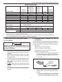
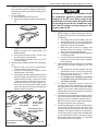
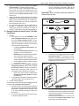
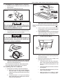
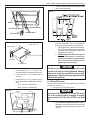
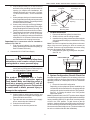
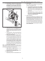
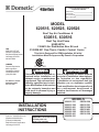
RECORD THIS INFORMATION
FOR FUTURE REFERENCE BEFORE
INSTALLING THE UNIT:
Model Number
Serial Number
Date Purchased
Place of Purchase
MODEL
620515, 620525, 620526
Roof Top Air Conditioner &
630515, 630516
Roof Top Heat Pump
USED WITH
3106615 Air Distribution Box Kit and
TM
3109228.001 Duo-Therm Comfort Control Center
USA
SERVICE OFFICE
Dometic Corporation
509 South Poplar Street
LaGrange, IN 46761
260-463-4858
CANADA
Dometic Distribution
866 Langs Drive
Cambridge, Ontario
CANADA N3H 2N7
(519) 653-4390
For Service Center
Assistance Call:
800-544-4881
This Unit Is Designed For OEM Installation. All Initial
Installations Must Be Approved By Dometic Corporation
C
US
This manual must be read and understood before installation, adjustment, service, or maintenance
is performed. This unit must be installed by a qualified service technician. Modification of this product
can be extremely hazardous and
could result in personal injury or
property damage.
Lire et comprendre ce manuel avant de
procéder à l'installation, à des réglages,
de l'entretien ou des réparations.
L'installation de cet appareil doit être
effectuée par un réparateur qualifié.
Toute modification de cet appareil peut
être extrêmement dangereuse et
entraîner des blessures ou dommages
matériels.
MODELS
INSTALLATION
INSTRUCTIONS
REVISION
Form No. 3109529.069 1/04
(Replaces 3109529.051)
(French 3109604.060)
©2004 Dometic Corporation
LaGrange, IN 46761
Important: These Instructions
must stay with unit.
Owner read carefully.
1
620515.321
620515.326
620515.421
620525.321
620525.326
620525.421
620526.321
620526.326
630515.321
630515.326
630515.421
630516.321
630516.326
620515, 620525, 620526, 630515 & 630516 Installation Instructions
GENERAL INFORMATION
SAFETY INSTRUCTIONS
A. Product features or specifications as described or illustrated are subject to change without notice.
This manual has safety information and instructions
to help users eliminate or reduce the risk of accidents and injuries.
B. This Air Conditioner Is Designed For:
1. Installation on a recreational vehicle during the time
the vehicle is manufactured.
2. Mounting on the roof of a recreational vehicle.
3. Roof construction with rafters/joists on minimum of
16 inch centers.
4. Minimum of 2.00 inches and maximum of 4.00
inches distance between roof to ceiling of recreational vehicle. Alternate installation methods will
allow forroofs more than 4.00 inches thick.
RECOGNIZE SAFETY INFORMATION
!
C. The ability of the air conditioner to maintain the desired
inside temperature depends on the heat gain of the RV.
Some preventative measures taken by the occupants of
the RV can reduce the heat gain and improve the
performance of the air conditioner. During extremely
high outdoor temperatures, the heat gain of the vehicle
may be reduced by:
1. Parking the RV in a shaded area
2. Using window shades (blinds and/or curtains)
3. Keeping windows and doors shut or minimizing
usage
4. Avoiding the use of heat producing appliances
This is the safety-alert symbol. When you see this
symbol in this manual, be alert to the potential for
personal injury.
Follow recommended precautions and safe operating instructions.
UNDERSTAND SIGNAL WORDS
Operation on High Fan/Cooling mode will give optimum or
maximum efficiency in high humidity or high outside temperatures.
A signal word , WARNING OR CAUTION is used
with the safety-alert symbol. They give the level of
risk for potential injury.
Starting the air conditioner early in the morning and giving it
a "head start" on the expected high outdoor ambient will
greatly improve its ability to maintain the desired indoor
temperature.
! WARNING indicates a potentially hazardous situation which, if not avoided, could result in
death or serious injury.
For a more permanent solution to high heat gain, accessories like A&E outdoor patio and window awnings will reduce
heat gain by removing the direct sun. They also add a nice
area to enjoy company during the cool of the evening.
! CAUTION indicates a potentially hazardous situation which, if not avoided may result in
minor or moderate injury.
D. Condensation
Note: The manufacturer of this air conditioner will not be
responsible for damage caused by condensed moisture on
ceilings or other surfaces. Air contains moisture and this
moisture tends to condense on cold surfaces. When air
enters the RV, condensed moisture may appear on the
ceiling, windows, metal parts, etc. The air conditioner removes this moisture from the air during normal operation.
Keeping doors and windows closed when this air conditioner
is in operation will minimize condensed moisture on cold
surfaces.
CAUTION
used without the safety alert
symbol indicates, a potentially hazardous situation which, if not avoided may result in property
damage.
Read and follow all safety information and instructions.
2
620515, 620525, 620526, 630515 & 630516 Installation Instructions
SPECIFICATIONS
MODEL NUMBER
Nominal Capacity (BTU/HR) *
Electrical Rating
Compressor Rated Load Amps
Fan Motor Rated Load Amps
Compressor Locked Rotor Amps
Fan Motor Locked Rotor Amps
SCFM - High Speed Max./Min.
Refrigerant (R22) oz.
Minimum Wire Size **
AC Circuit Protection
(User Supplied)
DC Circuit Protection
(User Supplied)
Installed Weight (Pounds)
Minimum Generator
1 UNIT
Size ***
2 UNITS
*
**
***
620515.321
620526.321
620515.326
620526.326
620515.421
620525.421
13,500
620525.321
630516.321
620525.326
630516.326
13,500
15,000
115 VAC, 60 Hz., 1 PH.
11.5
12.4
12.0
3.1
3.1
3.3
50.0
60.0
64.0
8.8
8.8
8.5
335/250
380/250
17
15.5
21.5
12 AWG Copper up to 24 ft.
20 Amp Time Delay Fuse or
HACR Circuit Breaker
Installation must comply with all National,
State, Province and/or Local Electrical Codes
102
102
104
3.5 KW
5.0 KW
630515.421
13,500
12.0
3.1
50.0
8.8
630515.321
630515.326
13,500
19.5
12.4
3.1
60.0
8.8
335/250
24.5
102
102
Maximum unit performance achieved at full rated voltage.
For lengths over 24 ft., consult the National Electrical Code.
Dometic Corporation gives general guidelines for generator requirements. These guidelines come from experiences people have
had in actual applications. When sizing the generator, the total power usage of your recreational vehicle must be considered. Also
keep in mind generators lose power at high altitudes and from lack of maintenance.
INSTALLATION INSTRUCTIONS
B. Choosing Proper Location For The Air
Conditioner
A. Precautions
This air conditioner is specifically designed for installation on
the roof of a recreational vehicle (RV). When determining your
cooling requirements, the following should be considered:
• Size of RV;
• Window area (increases heat gain);
• Amount of insulation in walls and roof;
• Geographical location where the RV will be used;
• Personal comfort level required.
1. Normal Location-The air conditioner is designed to
fit over an existing roof vent opening. When the vent
is removed, it normally creates a 14-1/4" X 14-1/4"
Improper installation may damage equipment/
could endanger life, cause serious injury and/
or property damage.
1. Read Installation and Operating Instructions carefully before attempting to start your air conditioner
installation.
2. Dometic Corporation will not be liable for any damages or injury incurred due to failure in following
these instructions.
3. Installation must comply with the National Electrical
Code ANSI/NFPA-70 and CSA Standard C22.1
(latest edition and any State or Local Codes or
regulations.
4. DO NOT add any devices or accessories to this air
conditioner except those specifically authorized by
Dometic.
5. This equipment must be serviced by qualified personnel and some states require these people to be
licensed.
(±1/8") opening.
FIG. 1
Roof Vent
Opening
2. Other Locations-When no roof vent is available or
another location is desired, the following is recommended:
a. For one unit installation: The air conditioner
should be mounted slightly forward of center
(front to back) and centered from side to side.
3
620515, 620525, 620526, 630515 & 630516 Installation Instructions
b. For two unit installations: Install one Air Conditioner 1/3 and one Air Conditioner 2/3’s from
front of RV and centered from side to side.
FIG. 2
1/2 L
FIG. 4
4"
7-1/8”
4-1/8”
L
2/3 L
L
4"
21-3/8”
1/3 L
14-1/4" x 14-1/4”
(±1/8”) OPENING
REAR
OF
UNIT
Center Line
of Unit
7-1/8”
KEEP THESE AREAS
FREE OF OBSTRUCTIONS
It is preferred that the air conditioner be installed in a relatively
flat and level roof section measured with the RV parked on
a level surface.
Note: A 8° slant to either side, or front to back, is acceptable
for 620515, 620525, 620526, 630515 and 630516 series.
12"
+
-1/8
2 7/8
3. After Location Has Been Selected:
a. Check for obstructions in the area where air
conditioner will be installed. See FIG. 3 & 4.
b. The roof must be designed to support 130
poundswhen the RV is in motion. Normally a
200 lb. static load design will meet this requirement.
4
4
2 7/8
CAUTION
It is the responsibility of the installer of this
air conditioner system to ensure structural
integrity of the RV roof. Never create a low
spot on the roof where water will collect. Water standing around the air conditioner may
leak into the interior causing damage to the
product and the RV.
C. Roof Preparation
1. Opening Requirements - Before preparing the ceiling opening, the type of system options must be
decided upon. If a remote sensor is to be used,
provision must be made for it. If the load shed option
is to be used, wires must be run from the load shed
control to the Dometic A/C. If a furnace is to be
connected, wires must be run from the furnace to the
Dometic A/C. Read all of the following instructions
before beginning the installation.
If a roof vent opening will not be used a 14-1/4" x 141/4" (±1/8") opening must be cut through the roof and
ceiling of the RV. This opening must be located
between the roof reinforcing members.
c. Check inside the RV for air box obstructions
(i.e. door openings, room dividers, curtains,
ceiling fixtures, etc.) See FIG. 3 & 4.
FIG. 3
9-1/2"
9-1/2"
28-3/4"
There may be electrical wiring between the
roof and the ceiling. Disconnect 115 volt AC
power cord and the positive (+) 12 volt DC terminal at the supply battery. Failure to follow
this instruction may create a shock hazard
causing death or severe personal injury.
39"
28-3/4"
39"
20"
2-1/2"
22"
4
620515, 620525, 620526, 630515 & 630516 Installation Instructions
The 14-1/4" x 14-1/4" (±1/8") opening is part of the
return air system of the Air Conditioner and must be
finished in accordance with NFPA Standard 501C
Section 2.7.2.
2. Roof Vent Removal
a. Unscrew and remove the roof vent.
b. Remove all caulking compound around opening.
CAUTION
It is the responsibility of the installer of this
air conditioner system to ensure structural
integrity of the RV roof. Never create a low
spot on the roof where water will collect. Water standing around the air conditioner may
leak into the interior causing damage to the
product and the RV.
FIG. 5
D. Wiring Requirements
1. Route a copper 12 AWG, with ground, 115 VAC
supply line from the fuse or circuit breaker box to the
roof opening.
a. This supply line must be located in the front
portion of the 14-1/4" x 14-1/4" (±1/8") opening.
b. The power MUST be on a separate 20 amp time
delay fuse or HACR circuit breaker.
c. Make sure that at least 15" of supply wire
extends into the roof opening. This ensures
easy connection at the junction box.
d. Wiring must comply with all National, State and
Local Wiring Codes.
e. Use a steel sleeve and a grommet or equivalent
methods to protect the wire where it passes
into the opening.
2. Route a dedicated 12 VDC supply line (18-22 AWG)
from the RV's converter or battery to the roof
opening.
a. This supply line must be located in the front
portion of the 14-1/4" x 14-1/4" (±1/8") opening.
b. Make sure that at least 15" of supply wire
extends into the roof opening.
c. In a multiple zone installation, this wiring
is required in only one of the 14-1/4" x 141/4" (±1/8") openings.
3. If a Remote Temperature Sensor is used, the
connector end must be routed to the roof opening of
the system which it will control. Make sure that at
least 15" of the sensor cable extends into the roof
opening. Refer to the Remote Sensor Instructions
for details of the installation.
4. If a furnace is to be controlled by the system, the two
furnace thermostat leads must be routed to the roof
opening of the air conditioner that will control it.
Make sure that at least 15" of the furnace thermostat wires extend into the roof opening.
5. If an Energy Management System (load shed feature) is to be used with the control, two wires must
be routed to the roof opening of the zone to be
managed. The signal required for this function is
normally open relay contact. When the EMS calls
for the compressor to shut off, the relay contacts
should close. Make sure at least 15" of the EMS
wires extend into the roof opening.
c. Seal all screw holes and seams where the roof
gasket is located. Use a good grade of all
weather sealant.
d. If the opening exceeds 14-3/8" x 14-3/8", it will
be necessary to install spacers.
e. If the opening is less than 14-1/8" x 14-1/8", it
must be enlarged.
3. New Opening-(Installation Other Than Vent Opening)
a. Mark a 14-1/4" x 14-1/4" (±1/8") square on the
roof and carefully cut the opening.
b. Using the roof opening as a guide, cut the
matching hole in the ceiling.
d. The opening created must be framed to provide
adequate support and prevent air from being
drawn from the roof cavity. Lumber 3/4" or more
in thickness must be used. Remember to provide an entrance hole for power supplies, furnace wiring, 4-conductor control cable, remote
sensor and load shed (Energy Management
System) options as desired.
FIG. 6
Do Not Cut Roof
Structure Or
Rafters
Good-Rafters
Supported By
Cross Beams
3/4" Min.
Leave Access for Power
Supply Wiring
Good LocationBetween Roof
Rafters
Frame Opening So It
Won't Collapse When
Bolting Down
15" min.
5
620515, 620525, 620526, 630515 & 630516 Installation Instructions
6. Route a 4-conductor control cable from the Comfort
Control Center™ mounting position into the
14-1/4" x 14-1/4" (±1/8") roof opening. Make sure
that at least 15" of the wire extends into the roof
opening and 6" extend from the wall at the mounting
position of the Comfort Control Center™. See
Section E-2.
7. In the event that other Air Conditioners are installed
(additional zones) an additional 4-conductor control
cable must be routed to the other Air Conditioners.
Make sure that at least 15" of the wire extends into
the roof opening. See FIG. 21.
8. If an automatic generator start kit (AGS) will be
installed, a 4-conducter control cable must be
routed from the last air conditioner to location of
AGS kit. Follow AGS kit instructions for installation.
c. The control cable must be terminated with two
(2) RJ-11 telephone connectors. Refer to the
crimp tool manufacture for crimping instructions.
Important: RJ-11 connectors must be installed as
shown in FIG. 7A & 7C.
FIG. 7A
FIG. 7B
E. Dometic Comfort Control Center™ & Cable
Installation
FIG. 7C
1. Location
a. If the system is to be used WITHOUT a Remote Temperature Sensor, the proper location of the Comfort Control Center™ is very
important to ensure that it will provide a comfortable RV temperature. Observe the following
rules when selecting a location:
• Locate the Comfort Control Center™ 54"
above the floor.
• Install the Comfort Control Center™ on a
partition, not on an outside wall.
• NEVER expose it to direct heat from lamps,
sun or other heat producing items.
• Avoid locations close to doors that lead
outside, windows or adjoining outside walls.
• Avoid locations close to supply registers
and the air from them.
b. If the system is to be used WITH a Remote
Temperature Sensor in ALL zones, the Comfort Control CenterTM may be mounted anywhere that is convenient in the coach. Try to
avoid hard to reach and hard to see areas.
• Refer to the instructions provided with the
Remote Temperature Sensor for details
of installation.
c. A 3/8" diameter hole will be needed to route the
cable through the wall. See Section D-3.
2. Control Cable Installation
A 4-conductor control cable must be routed from the roof
opening to the Comfort Control CenterTM.
a. Choose the shortest, most direct route from the
14-1/4" x 14-1/4" (±1/8") opening to the Comfort Control CenterTM location selected. Leave
6" of cable extending through the wall. See
Section D-6.
b. The control cable that should be used is a flat,
4-conductor telephone cable.
Pin 1
RJ-11 Connector
Flat Four Conductor Cable
3. Comfort Control CenterTM Installation
a. Carefully remove the base plate from the Comfort Control CenterTM. This may be accomplished by inserting a small screwdriver under
the tab on the bottom edge of the front cover
and gently prying. See FIG. 8.
FIG. 8
MO
DE
N
FA
P
TEM
UP
DO
WN
ZO
NE
OF
F
ON
Insert Screwdriver
under Tab
b. Insert the control cable through the hole in the
base plate and mount the plate to the wall with
two (2) screws provided. Check the alignment to
ensure level installation.
c. Install the control cable RJ-11 connector into
the back of the Comfort Control Center™ and
gently press onto the base plate.
6
620515, 620525, 620526, 630515 & 630516 Installation Instructions
F. Placing the Air Conditioner On The Roof
FIG. 11
1.
Remove the air conditioner from the carton and
discard carton.
2. Place the air conditioner on the roof.
UPPER
DUCT
FIG. 9
SIDE W ITHOUT
TAB T O R EAR
OF A PPLIANCE
LOWER
R
DUCT
c. Remove the upper duct from the ceiling template and locate it over the blower discharge.
Note: The edge without the flange installs toward the rear of
the RV.
d. Use two (2) #10 x 3/8" screws to hold the duct
to the base pan. The holes are pre-punched in
the pan for each location.
e. Check gasket alignment over roof opening and
adjust if necessary. Unit may be moved from
below by slightly lifting. See FIG. 12.
This unit weighs approximately 100 pounds.
To prevent back injury, use a mechanical hoist
to place Air Conditioner on roof.
3. Lift and place the unit over the prepared opening
using the gasket on the unit as a guide.
CAUTION
FIG. 12
Center Unit From Below
Do not slide the unit. This may damage the
neoprene gasket attached to the bottom and
may create a leaky installation.
FIG. 10
FRONT
Roof
Gasket
f.
Reach up into the return air opening and pull the
electrical cord down.
g. Mount the junction box to the ceiling in the
following location. See FIG. 13.
• Locate the junction box near ceiling template. Locate opposite discharge duct end
and on same side as discharge duct. See
FIG. 14
• Center long side of junction box on center of
mounting bolt.
• Place edge of box approximately 1/2" from
edge of ceiling template.
• Attach junction box to ceiling of coach
using two (2) #10 x 1/2" screws provided.
4. Place the Air Box Kit inside the RV. This box
contains mounting hardware for the air conditioner
and will be used inside the RV.
This completes the outside work. Minor adjustments
can be done from the inside of the RV if required.
G. Installing The Air Conditioner
1. Discharge Duct & Ceiling Template Installation.
a. Remove the air box and mounting hardware
from their carton. The upper duct is shipped
inside the lower duct which is part of the ceiling
template.
b. Locate the three 8" x 1/4" x 20 unit mounting
bolts, junction box cover and Romex connector
in the 3107180.006 bolt kit.
7
620515, 620525, 620526, 630515 & 630516 Installation Instructions
j.
FIG. 13
Take the ceiling template and slide the lower
duct over the upper duct.
FIG. 16
Gasket
Remote Sensor
Low Voltage Wires
Junction Box
Control Cables
h. Install the Romex connector in the junction box.
k. Hold the ceiling template with one hand and with
the other, install the three 1/4" mounting bolts
through the template and into the base pan.
• Finger-tighten the (3) bolts and check alignment. There should be an equal opening on
each side and the rear flange must be tight
against the roof opening.
• EVENLY tighten the bolts to a torque of
40 to 50 inch pounds. This will compress the roof gasket to approximately
1/2". The bolts are self locking so over
tightening is not necessary.
Ceiling
FIG. 14
Discharge Air
Junction Box
14-1/4" x 14-1/4" (±1/8")
Junction
Air Conditioner
CAUTION
i
FIG. 15
Measure the ceiling thickness:
• If the distance is 2" to 3" remove the
perforated tabs from the bottom duct only.
• If the distance is 3" to 4" install ducts as
received.
• If the distance is 4" to 6" (maximum thickness), optional Duct and Bolt Kits are available:
Duct (Part No. 318556.000)
Bolts (Part No. 3100895.006)
CENTER A /C
FROM BEL OW
If bolts are left loose there may not be an adequate roof seal or if over tightened, damage
may occur to the air conditioner base or ceiling template. Tighten to torque specifications
listed in this manual.
H. Wiring Of System
Reach up into the return air opening and pull the remaining
wires down. See FIG. 13.
1. Connection Of Low Voltage Wires
CAUTION
GASKET
Disconnect the positive (+) 12 volt DC terminal at the supply battery. Damage to equipment could occur if the 12 volt DC is not shut
off.
a. Route Remote Temperature Sensor cable, if
applicable, and attach it to the connector that
matches its color protruding from the return air
opening.
MEASURE
CEILING
THICKNESS
8
620515, 620525, 620526, 630515 & 630516 Installation Instructions
b. Connect the previously run 12 VDC to the red
and black wires protruding from the return air
opening. (In multiple zone installations, this
needs to be doneat only one zone.) Connect
+12 VDC to the red wire; –12 VDC to the black
wire.
c. Connect the previously run furnace thermostat
wires (if applicable) to the blue wires protruding
from the return air opening. The polarity of these
connections does not matter.
d. Connect the previously run Energy Management System wires (if applicable) to the yellow
wires protruding from the return air opening. The
polarity of these connections does not matter.
e. Terminate the 4-conductor control cable(s) protruding into the 14-1/4" x 14-1/4" (±1/8") roof
opening. The cable(s) must be terminated with
a telephone RJ-11 connector. Refer to the crimp
tool manufacturer for crimping instructions.
Important: RJ-11 connectors must be installed as
shown in FIG. 7A & 7C.
f. Plug the control cable(s) into the telephone
jack(s) protruding from the return air opening. (It
does not matter which one.)
FIG. 17
Ceiling
Template
Junction Box
Discharge Air
Duct
14-1/4" x 14-1/4" (±1/8")
Opening
Junction
Box Cover
Air Conditioner
Mounting bolts
I.
Air Box Installation
1. Remove the two filter-grilles from the air box.
2. Slide the air box over the ceiling template.
3. Install the four (4) sharp pointed screws through the
air box legs and into the pre-punched holes in ceiling
template.
Note: There are four optional mounting holes on the outer
edge of the return air opening for which no screws are
provided. These are only required where an uneven ceiling
does not allow proper fitting of the air box.
4. Install the filter-grilles by pushing them into place.
See FIG. 18.
2. Connection Of 115 Volt Power Supply
FIG. 18
CEILING
TEMPLATE
CELING
T EMPLATE
AIR
AIR BOX
Disconnect 115 volt AC. Failure to follow these
instructions could create a shock hazard
causing death or severe personal injury.
a. Route power supply line through Romex connector and into junction box on side away from
the ceiling template. Tighten connector.
J. System Configuration, Reset & Check Out
This product is equipped with a 3-wire
(grounded) system for protection against
shock hazard. Make sure that the prduct is
wired into a properly grounded 115 volt AC
circuit and the polarity is correct. Failure to do
so could result in death, personal injury or
damage to the equipment.
Now that the system is installed, it is necessary to check all
operations and then configure the electronics. Refer to the
operating manual for a description of the air conditioner
operation.
1. Electronic Control Kit Configuration
Depending on the equipment options installed by the
recreational vehicle manufacturer, the appropriate dip
switches will need to be switched to the "ON" position.
See FIG. 19. Placing the switch in the "ON" position
selects that option.
Note: Dip switches are in the "OFF" position when shipped
from the factory except for models supplied with the heat strip
factory installed, (620515).For this model , the #1 dip switch
will be in the "ON" position. To gain access to the dip
switches, theshroud must be removed from the unit. Remove
the four mounting screws around the perimeter of the unit.
Next remove the electrical box cover. (The electrical box will
be on the curb side of the RV after installation).
b. Connect white to white; black to black; and
green to green or bare copper wire using appropriate sized twist connectors.
c. Tape the twist wire connectors to the supply
wire to assure they don't vibrate off.
d. Push the wires into the box.
e. Install the cover onto the junction box.
9
620515, 620525, 620526, 630515 & 630516 Installation Instructions
a. Zone selection - when two or more units are
installed and controlled by one Comfort Control CenterTM, the second unit becomes Zone
2, the third unit Zone 3 and the fourth unit Zone
4. The appropriate zone dip switch must be set
in each electronic control kit for Zone 2, 3 and 4.
2. System Reset
After setting the dip switches in the electronic
control kit, do a system reset.
a. Turn the ON/OFF switch to the "OFF" position.
b. Simultaneously depress and hold the MODE
and ZONE push-buttons while turning the ON/
OFF switch to "ON". FF should appear in LCD
display until the mode and zone push-buttons
are released.
c. When a dip switch is turned on after initial
configuration, a system reset will need to be
done before the Comfort Control Center™ will
recognize the updated selection.
3. System Checkout
We recommend that power be supplied to the air
conditioner and check for proper operation. Verify
that all features of the installed system work. See
Comfort Control Center™ Operating Instructions.
Check fan speeds, cooling mode, heat pump mode,
furnace (if connected) and heat strip. If the features
do not work, check all wiring and confirm that the
correct options have been selected on the Electronic Control Board.
FIG. 19
1 2 3 4 5 6 7 8
ON
HEAT STRIP
ZONE 2
ZONE 3
ZONE 4
FURNACE
DIFFERENTIAL
STAGE
GEN START
DIP
SWITCHES
b. Heat strip selection - For units with a heat strip
installed at the factory (Model 620515), the #1
dip switch will be in the "ON" position. All other
models will have the dip switches in the "OFF"
position.
c. Furnace selection - when a furnace has been
connected to a zone, place the furnace dip
switch "ON" for that zone.
d. Differential - differential is the temperature difference between the "ON/OFF" cycle of the thermostat. The normal differential is preset in the
circuit board with the dip switch set to the "OFF"
position. In some situations, it may be necessary to decrease the Differential. The location of
the thermostat may create a condition where
the normal Differential will not maintain your
comfort zone. If this occurs, the Differential can
be shortened by placing the Differential dip
switch to the "ON" position.
Note: Setting the Differential dip switch should only be
required when installation conditions are less than desirable
and is not covered under the limited warranty.
e. Stage selection - stage is not used on these
units. Leave in the "OFF" position.
f. Gen start selection - leave in the "OFF" position.
g. Replace the unit electrical box cover.
h. Replace the shroud.
i. Repeat this procedure for each additional zone.
10
620515, 620525, 620526, 630515 & 630516 Installation Instructions
FIG. 20
Air Conditioner
Rear
Roof Mount Assembly
Front
Upper Discharge Air Duct
Roof Line
Roof Reinforcement
Member
Framing, Return Air Duct
14-1/4" x 14-1/4" (±1/8")
Opening
Lower Discharge Air Duct
(Attached to Ceiling Template)
Ceiling Template
Unit Mounting Bolts
Mounting Legs
Mounting Legs
Air Box
FIG. 21
REAR REMOTE SENSOR
(Required with Second
Air Conditioner)
115V AC
REAR A/C
14-1/4" x 14-1/4"
(±1/8”) OPENING
4-CONDUCTOR
CONTROL CABLE
FURNACE
2 WIRES
BREAKER BOX
4-CONDUCTOR
CONTROL CABLE
OPTIONAL
FURNACE
DOMETIC COMFORT
CONTROL CENTER
FURNACE
FURNACE
2 WIRES
14-1/4" x 14-1/4"
(±1/8”) OPENING
OPTIONAL FRONT
REMOTE SENSOR
12V DC INPUT
2 WIRES
115V AC
FRONT A/C
11
620515, 620525, 620526, 630515 & 630516 Installation Instructions
WIRING DIAGRAM FOR MODELS
620515.321, 620515.326, 620515.421, 620525.321,
620525.326, 620525.421, 620526.321 & 620526.326
PASSED
DIELECTRIC
FREEZE
CONTROL
FACTORY WIRING
SPLICE CAP
FIELD WIRING
REMOTE
SENSOR
CABLE
BLK
RJ-11 CABLE
TO COMFORT
CONTROL
O.L.
MOTOR
RED
BLK
WHITE
WHITE
R
BRN
BLK
P5
P4
FAN
C
PTCR
A/C
POWER
3 AMP
WHT
BLK
T5
MODULE
FUSE
WHT
BOARD
FURNACE
FURNACE
12V 12V +
INDICATORS
IF USED
K1
NO
HEATER ELEMENT
COM
WHT
BLK
GRN/YEL
T1
T3
REMOTE
SENSOR
CABLE
SPLICE CAP
WHT
BLK
A/C
POWER
MODULE
BOARD
P3
P4
P5
F1
3 AMP
FUSE
P2
T5
YEL
YEL
BLU
K6
P1
RED
WHT
START CAP
RED
NO
O.L.
MOTOR
R
BLK
S
C
BLK
BLK
WHT
BRN
BLK
RED
RUN CAP
FAN
WHT
P3
P4
P5
F1
P2
P1
C
PTCR
AMBIENT
SENSOR
3 AMP
FUSE
WHT
WHT
HERM
T5
RED
WHT
START CAP
BLK
RED
P6
BLK
LOAD SHED
LOAD SHED
FURNACE
FURNACE
12V 12V +
COM
REVERSING VALVE
BLK
YEL
YEL
K1
BLU
NO
BLU
FIELD WIRING
BLK
FACTORY WIRING
COM
REVERSING VALVE
BLK
SPLICE CAP
RED
BLK
T1
GRN/YEL
GRN/YEL
T2
WHT
BLK
3106613.023
A/C
POWER
MODULE
BOARD
C
COMPRESSOR
GRN/YEL
RED
WHITE
HERM
BLK
RJ-11 CABLE
TO COMFORT
CONTROL
YEL
WHITE
FAN
WHT
COM
NO
RED
RUN CAP
WHT
BLK
T3
BLK
WHT
BRN
BLK
FREEZE
CONTROL
REMOTE
SENSOR
CABLE
C
BLK
BLK
RED
S
PTCR
K1
BLU
PASSED
DIELECTRIC
COMPRESSOR
O.L.
R
AMBIENT
SENSOR
P6
LOAD SHED
LOAD SHED
FURNACE
FURNACE
12V 12V +
BLK
CONDUCTORS
ONLY
WIRING DIAGRAM FOR MODELS
LATER VERSION
630515.321, 630515.326
630516.321, 630516.326
BLK
MOTOR
YEL
WHITE
60 Hz, 1O
USE COPPER
BLK
GRN/YEL
RED
115 VAC
GRN/YEL
T2
BLK
RJ-11 CABLE
TO COMFORT
CONTROL
MODELS
BLK
BLK
WIRING DIAGRAM FOR MODELS
EARLY VERSION
630515.321, 630515.326
630515.421
630516.321, 630516.326
FACTORY WIRING
ON SOME
LIMIT SWITCH
NO
3106682.036
FIELD WIRING
NOT USED
COM
K6
SOLAR OR
DIRTY FILTER
RED
START CAP
WHT
YEL
YEL
BLU
BLU
BLK
RED
LOAD SHED
RED
HERM
P6
LOAD SHED
RED
RUN CAP
WHT
P1
P2
S
C
WHT
YEL
BLK
BLK
P3
F1
COMPRESSOR
GRN/YEL
BLK
SOLAR OR
DIRTY FILTER
INDICATORS
IF USED
115 VAC
60 Hz,
1o
USE COPPER
CONDUCTORS
ONLY
K6
COM
T1
T3
BLK
NO
GRN/YEL
GRN/YEL
T2
WHT
BLK
BLK
115 VAC
60 Hz, 1o
USE COPPER
CONDUCTORS
ONLY
3106613.049
12