1
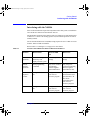
N4010-90086.book Page i Friday, April 4, 2014 3:12 PM
Getting Started Guide
Wireless Connectivity Test Set
N4010A
Manufacturing Part Number: N4010-90086
Printed in Malaysia
April 2014
© Copyright Agilent Technologies UK Limited 2006, 2009, 2013, 2014
N4010-90086.book Page ii Friday, April 4, 2014 3:12 PM
General
The material contained in this document is provided “as is,” and is subject to being
changed, without notice, in future editions. Further, to the maximum extent
permitted by applicable law, Agilent disclaims all warranties, either express or
implied with regard to this manual and any information contained herein, including
but not limited to the implied warranties of merchantability and fitness for a
particular purpose. Agilent shall not be liable for errors or for incidental or
consequential damages in connection with the furnishing, use, or performance of
this document or any information contained herein. Should Agilent and the user
have a separate written agreement with warranty terms covering the material in this
document that conflict with these terms, the warranty terms in the separate
agreement will control.
ii
N4010-90086.book Page iii Friday, April 4, 2014 3:12 PM
Legal Information
Certification
Agilent Technologies certifies that this product met its published specifications at
the time of shipment from the factory. Agilent Technologies further certifies that its
calibration measurements are traceable to the United States National Institute of
Standards and Technology, to the extent allowed by the Institute’s calibration
facility, and to the calibration facilities of other International Standards Organization
members.
Safety Symbols
The following symbols on the Test Set and in the documentation indicate
precautions which must be taken to maintain safe operation of the Test Set.
This is the ‘Caution - Refer to Instruction
Documentation’ Symbol. The product is marked with
this symbol when it is necessary for the user to refer to
the instructions in the supplied documentation.
Alternating current (AC)
This symbol indicates the position of the operating
switch for ‘Stand-by’ mode. Note, the Test Set is NOT
isolated from the mains when the switch is in this
position. To isolate the Test Set, the mains coupler
(mains input cord) should be removed from the power
supply.
iii
N4010-90086.book Page iv Friday, April 4, 2014 3:12 PM
Safety Notices
This guide uses warnings and cautions to denote hazards
WARNING
Warning denotes a hazard. It calls attention to a procedure, which if not correctly
performed or adhered to, could result in injury or loss of life. Do not proceed beyond
a warning until the indicated conditions are fully understood and met.
CAUTION
Caution denotes a hazard. It calls attention to a procedure, which if not correctly
performed or adhered to, could result in damage to or destruction of the instrument.
Do not proceed beyond a caution until the indicated conditions are fully understood
and met.
General Safety Information
The following general safety precautions must be observed during all phases of
operation, service, and repair of this Test Set. Failure to comply with these
precautions or with specific warnings elsewhere in this manual violates safety
standards of design, manufacture, and intended use of the Test Set. Agilent
Technologies assumes no liability for the customer’s failure to comply with these
requirements.
WARNING
This is a Safety Class I Test Set (provided with a protective earthing ground,
incorporated in the power cord). The mains plug shall only be inserted in a
socket outlet provided with a protective earth contact. Any interruption of the
protective conductor inside or outside of the Test Set is likely to make the Test
Set dangerous. Intentional interruption is prohibited.
DO NOT operate the product in an explosive atmosphere or in the presence of
iv
N4010-90086.book Page v Friday, April 4, 2014 3:12 PM
flammable gasses or fumes.
DO NOT perform procedures involving cover or shield removal unless you are
qualified to do so: Operating personnel must not remove equipment covers or
shields. Procedures involving the removal of covers and shields are for use by
service-trained personnel only.
DO NOT service or adjust alone: Under certain conditions, dangerous voltages may
exist even with the equipment switched off. To avoid dangerous electrical shock,
service personnel must not attempt internal service or adjustment unless another
person, capable of rendering first aid and resuscitation, is present.
DO NOT operate damaged equipment: Whenever it is possible that the safety
protection features built into this product have been impaired, either through
physical damage, excessive moisture, or any other reason, REMOVE POWER and
do not use the product until safe operation can be verified by service-trained
personnel. If necessary, return the product to a Agilent Sales and Service Office for
service and repair to ensure the safety features are maintained.
DO NOT substitute parts or modify equipment: Because of the danger of
introducing additional hazards, do not install substitute parts or perform any
unauthorized modification to the product. Return the product to an Agilent Sales and
Service Office for service and repair to ensure the safety features are maintained.
CAUTION
Before switching on this Test Set, make sure that the correct fuse is installed and
ensure the power supply voltage is in the specified range.
CAUTION
Mains supply voltage fluctuations should not exceed +/- 10% of the nominal
selected line voltage.
v
N4010-90086.book Page vi Friday, April 4, 2014 3:12 PM
WARNING
Appliance coupler (mains input power cord) is the power disconnect device. Do
not position the Test Set such that access to the coupler is impaired.
Acknowledgements
Bluetooth® and the Bluetooth Logo® are trademarks owned by Bluetooth SIG, Inc.,
U.S.A. and licensed to Agilent Technologies, Inc.
MATLAB® is a U.S. registered trademark of The Math Works, Inc.
Microsoft® is a U.S. registered trademark of Microsoft Corporation. Windows®
and MS Windows® are U.S. registered trademarks of Microsoft Corporation.
Pentium® is a U.S. registered trademark of Intel Corporation.
vi
N4010-90086.book Page vii Friday, April 4, 2014 3:12 PM
Contents
1. Getting Started
Welcome . . . . . . . . . . . . . . . . . . . . . . . . . . . . . . . . . . . . . . . . . . . . . . . . . . . . . . . . . . . . . . . . . . . . . . . 2
Interfacing with the N4010A . . . . . . . . . . . . . . . . . . . . . . . . . . . . . . . . . . . . . . . . . . . . . . . . . . . . . . . . 3
Initial Inspection . . . . . . . . . . . . . . . . . . . . . . . . . . . . . . . . . . . . . . . . . . . . . . . . . . . . . . . . . . . . . . . . . 5
Adjusting the Carrying Handle . . . . . . . . . . . . . . . . . . . . . . . . . . . . . . . . . . . . . . . . . . . . . . . . . . . . . . 6
Turning the Test Set On . . . . . . . . . . . . . . . . . . . . . . . . . . . . . . . . . . . . . . . . . . . . . . . . . . . . . . . . . . . . 7
Minimum PC Requirements . . . . . . . . . . . . . . . . . . . . . . . . . . . . . . . . . . . . . . . . . . . . . . . . . . . . . . . 11
Installing the Measurement Software, Applications, and Help . . . . . . . . . . . . . . . . . . . . . . . . . . . . . 12
2. Making Your First Measurements
Selecting the Application Mode . . . . . . . . . . . . . . . . . . . . . . . . . . . . . . . . . . . . . . . . . . . . . . . . . . . .
Running a Confidence Check on the Front Panel (Bluetooth) . . . . . . . . . . . . . . . . . . . . . . . . . . . . .
Connecting USB, GPIB or LAN . . . . . . . . . . . . . . . . . . . . . . . . . . . . . . . . . . . . . . . . . . . . . . . . . . . .
Running a SCPI Confidence Check. . . . . . . . . . . . . . . . . . . . . . . . . . . . . . . . . . . . . . . . . . . . . . . . . .
Running a WLAN Confidence Check . . . . . . . . . . . . . . . . . . . . . . . . . . . . . . . . . . . . . . . . . . . . . . . .
Running the Graphical Measurement Application (GMA) N4017A. . . . . . . . . . . . . . . . . . . . . . . . .
Rack Mounting the Test Set. . . . . . . . . . . . . . . . . . . . . . . . . . . . . . . . . . . . . . . . . . . . . . . . . . . . . . . .
14
15
18
27
29
33
39
3. Regulatory Information
General Specifications . . . . . . . . . . . . . . . . . . . . . . . . . . . . . . . . . . . . . . . . . . . . . . . . . . . . . . . . . . . .
Compliance and Markings. . . . . . . . . . . . . . . . . . . . . . . . . . . . . . . . . . . . . . . . . . . . . . . . . . . . . . . . .
Regulatory Information . . . . . . . . . . . . . . . . . . . . . . . . . . . . . . . . . . . . . . . . . . . . . . . . . . . . . . . . . . .
Responsibilities of the Customer . . . . . . . . . . . . . . . . . . . . . . . . . . . . . . . . . . . . . . . . . . . . . . . . . . . .
Agilent Sales and Service Offices . . . . . . . . . . . . . . . . . . . . . . . . . . . . . . . . . . . . . . . . . . . . . . . . . . .
42
44
46
47
48
vii
N4010-90086.book Page viii Friday, April 4, 2014 3:12 PM
Contents
viii
N4010-90086.book Page 1 Friday, April 4, 2014 3:12 PM
1
Getting Started
Chapter 1
1
N4010-90086.book Page 2 Friday, April 4, 2014 3:12 PM
Getting Started
Welcome
Welcome
Welcome to the Agilent Technologies N4010A Wireless Connectivity Test Set’s
Getting Started Guide.
Use this guide with the N4010A, equipped with any option, to help you:
•
Inspect the Test Set.
•
Adjust the carrying handle.
•
Switch the Test Set on and confirm it passes the power-on self test.
•
Determine the minimum requirements for your PC.
•
Install the Measurement Software, Applications, and Help from the N4010A
CD-ROM.
•
Make connections to the rear panel.
•
Run a SCPI confidence check using the Connection Expert application.
•
Run a Bluetooth confidence check using front panel operation.
•
Run a Bluetooth confidence check using the remote interface option.
•
Run a WLAN confidence check using the Virtual Front Panel application.
•
Attach the rack mounting kits (supplied with option N4010A-AX4).
2
Chapter 1
N4010-90086.book Page 3 Friday, April 4, 2014 3:12 PM
Getting Started
Interfacing with the N4010A
Interfacing with the N4010A
Some of the measurments require that a Dynamic Link Library (DLL) is installed in
a PC and the PC connected to the N4010A Test Set.
Full Front Panel operation of the N4010A Test Set is limited to system functions and
to Bluetooth 1.1 and 1.2 RF Testing (option 101). Rear Panel operation via SCPI is
similarly limited.
802.11 WLAN and Bluetooth 2.0 (EDR) testing requires the use of a DLL accessed
from the .NET or COM environment.
Refer to Table 1-1 and Figure 1-1 on page 4 for more details.
Table 1-1
Test Set Control Differences Between Bluetooth and WLAN
Function
Bluetooth Test
Bluetooth EDR
Test
WLAN Test
Front Panel
Operation
Full control using front
Panel Keys and
displayed menu system
Limited to system
settings
Limited to system
settings
Remote
Interface
Operation
SCPI programming
commands
Only via PC resident
programming
interface Agilent
N4010 EDR Driver
Only using a PC
resident programming
interface Agilent
N4010 WLAN Test
Test
Sequence
Control
Configured within Test
Set
Configured with
your own test
executive program
Only Spectral Mask
measurement tests to
specified limits. All
other limits
configured within
your own test
executive program.
Test to Limits
Configured within Test
Set
Configured with
your own test
executive program
Configured within
your own test
executive program
Chapter 1
3
N4010-90086.book Page 4 Friday, April 4, 2014 3:12 PM
Getting Started
Interfacing with the N4010A
Table 1-1
Test Set Control Differences Between Bluetooth and WLAN
Function
Bluetooth Test
Control of
Test Device
via LMP commands
from Test Set and EUT
HCI control from test
executive
Remote
interfacing
GPIB, LAN and USB
Bluetooth EDR
Test
WLAN Test
DUT control from test
executive only using
device specific
drivers
USB 2.0 or LAN
preferred. GPIB
possible.
USB 2.0a or LAN
preferred. GPIB
possible.
a. This is not recommended when using Signal Studio as a waveform generator
Figure 1-1
N4010A Interfaces and DLLs
4
Chapter 1
N4010-90086.book Page 5 Friday, April 4, 2014 3:12 PM
Getting Started
Initial Inspection
Initial Inspection
Please inspect the shipping container for damage. If the shipping container or
packaging material is damaged, please keep it until the contents have been checked
mechanically and electrically. If there is mechanical damage, notify the nearest
Agilent Technologies office. Keep the damaged shipping materials (if any) for
inspection by the carrier and an Agilent representative. If required, you can find a
list of “Agilent Sales and Service Offices” on page 48.
Before continuing, please ensure you have read and understood the preceding safety
information.
Chapter 1
5
N4010-90086.book Page 6 Friday, April 4, 2014 3:12 PM
Getting Started
Adjusting the Carrying Handle
Adjusting the Carrying Handle
Adjust the carrying handle to carry the Test Set or view the display.
The carrying handle can be locked into three different positions.
Pull the handle outwards, rotate it to the required position and release it into
one of the three locks.
If you want to remove the handle, refer to “Rack Mounting the Test Set” on page
39.
6
Chapter 1
N4010-90086.book Page 7 Friday, April 4, 2014 3:12 PM
Getting Started
Turning the Test Set On
Turning the Test Set On
CAUTION
The Test Set has an autoranging power supply. Ensure the supply voltage is within
the range 100 Vac to 240 Vac and 50 Hz to 60 Hz.
1. Connect the Power Cord.
2. Check that the background LED is red.
Chapter 1
7
N4010-90086.book Page 8 Friday, April 4, 2014 3:12 PM
Getting Started
Turning the Test Set On
3. Turn the test set on and confirm the background LED is green.
4. The test set automatically steps through a self test routine. After this
routine you should see the following display...
5. The Test Set is now ready for use.
NOTE
If the test set has been stored in extremely cold conditions, beyond its normal
operating range, the display may require a few minutes to warm up and operate
normally.
8
Chapter 1
N4010-90086.book Page 9 Friday, April 4, 2014 3:12 PM
Getting Started
Turning the Test Set On
System Information
To verify your configuration, press the System key, an example is shown in Figure
1-2.
Figure 1-2
Typical System Configuration Screen
Chapter 1
9
N4010-90086.book Page 10 Friday, April 4, 2014 3:12 PM
Getting Started
Turning the Test Set On
What Can Go Wrong?
See this
Do this
Red LED not lit
Check that power is supplied to the test set.
Check the Test Set fuse. (see below)
Fails self test(s)
If there are any self-test failures the test set is
defective. Contact your nearest Agilent Service
Center (Refer to Agilent Sales and Service Offices
on page 48).
In line fuse
Spare fuse
10
Chapter 1
N4010-90086.book Page 11 Friday, April 4, 2014 3:12 PM
Getting Started
Minimum PC Requirements
Minimum PC Requirements
Some N4010A TestSet methods of operation require a higher preformance PC than
others. Viewing Help and controlling the Test Set using the SCPI command set
requires only moderate performance, while using the WLAN or Bluetooth EDR
DLLs requires more.
Refer to the specific requirements of the application if you are using additional
measurement software such as the Agilent 89607 VSA.
•
Windows® 2000 (SP4 or greater) or XP® Pro SP2 or XP® Home SP2.
•
700MHz Pentium® minimum to view Help files and remote interface operation
using the SCPI commands set, 1.6 GHz or better recommended for DLL
operation.
•
256 Mbytes RAM.
•
USB 2.0, GPIB or TCP/IP LAN connection to Test Set.
•
1024 x 768 pixel display.
•
CD-ROM Drive or Internet connection for application download.
•
Internet connection for license redemption. (if required)
In addition, to be able to run the N4010A CD-ROM and connect using the remote
interfaces, your PC must also have the following software components installed:
•
Microsoft .NET Framework 1.1 Service Pack 1 - This is required for the
operation of the N4010A CD-ROM and some of the content. If the .NET
Framework is not detected on your PC, it can be installed by following the
on-screen instructions after starting the N4010A CD-ROM.
You can explore the CD-ROM to view the Help files (.chm format) without the
.NET Framework installed on your PC.
•
Agilent I/O libraries version 14.1 or equivalent - I/O libraries are required for the
remote operation of the N4010A and for the operation of the N4010A Bluetooth
EDR DLL, the N4017A GMA, and the N4010A WLAN Test Suite. If I/O
libraries are not detected on your PC, Agilent IO libraries can be installed by
following the on-screen instructions after starting the N4010A CD-ROM.
Chapter 1
11
N4010-90086.book Page 12 Friday, April 4, 2014 3:12 PM
Getting Started
Installing the Measurement Software, Applications, and Help
Installing the Measurement Software, Applications, and
Help
The supplied N4010A Measurement Software, Applications, and Operating
Information CD-ROM contains all the applications, software components, and help
files needed for the Test Set to perform Bluetooth and 802.11 a/b/g WLAN device
tests.
Open the DVD box and refer to the Installation Guide contained inside.
Use the Installation Guide and, after starting the CD-ROM, the on-screen
instructions to view, copy, and install the Applications and Help Systems you
require.
NOTE
If your PC does not have autostart enabled, use Windows Explorer to locate and
double click the
(autorun.exe) file on the CD-ROM.
If the .NET Framework 1.1 SP1 is not detected on your PC, a message is displayed
asking you to confirm its installation from the N4010A CD-ROM. Confirm to
continue. If the .NET Framework is not installed the Installer halts and you cannot
proceed.
Typically, a PC re-start is required following the N4010A WLAN Test Suite
installation. If you are installing both WLAN and Bluetooth components, we
recommend that you install the N4010A WLAN Test Suite first, and install the
Bluetooth components following the PC re-start.
When you have completed the configuration of your PC and are ready to proceed,
continue in this Getting Started Guide at Chapter 2, “Making Your First
Measurements,” on page 13.
12
Chapter 1
N4010-90086.book Page 13 Friday, April 4, 2014 3:12 PM
2
Making Your First Measurements
Chapter 2
13
N4010-90086.book Page 14 Friday, April 4, 2014 3:12 PM
Making Your First Measurements
Selecting the Application Mode
Selecting the Application Mode
The purpose of this guide is to allow you to confirm the Test Set functions.
NOTE
For further detail read the help provided on the N4010A CD-ROM.
•
To perform a confidence check for Bluetooth local control only, refer to
“Running a Confidence Check on the Front Panel (Bluetooth)” on page 15.
•
To perform a confidence check for SCPI commands, refer to “Running a SCPI
Confidence Check” on page 27.
•
To perform a confidence check for WLAN, refer to “Running a WLAN
Confidence Check” on page 29.
•
To perform a confidence check for Bluetooth remote use with the N4017A
Graphical Measurement Application, refer to “Running the Graphical
Measurement Application (GMA) N4017A.” on page 33.
14
Chapter 2
N4010-90086.book Page 15 Friday, April 4, 2014 3:12 PM
Making Your First Measurements
Running a Confidence Check on the Front Panel (Bluetooth)
Running a Confidence Check on the Front Panel
(Bluetooth)
To operate Bluetooth testing from the Front Panel, your N4010A must be configured
with:
•
Option 101.
Refer to the N4010A web page at www.agilent.com/find/N4010A for firmware
updates.
NOTE
The N4010A Bluetooth Help file is provided on the CD.
To verify your configuration, press the System key, an example is shown in Figure
2-1.
Figure 2-1
Typical System Configuration Screen
To run a confidence check you also require a Bluetooth device, for example, a
Bluetooth enabled mobile phone.
1. Make the Equipment Under Test (EUT) discoverable. Refer to manufacturer’s
handbook for instructions.
2. Fix an antenna to the RF IN/OUT or connect EUT directly to the connector.
Shown in Figure 2-2.
Chapter 2
15
N4010-90086.book Page 16 Friday, April 4, 2014 3:12 PM
Making Your First Measurements
Running a Confidence Check on the Front Panel (Bluetooth)
Figure 2-2
Test Set RFIO Connections
3. Press the Config key.
Figure 2-3
Typical Configure Link Screen when ACL is Selected
4
5
4. Use the Arrow and Select keys to highlight and select an ACL Link as shown in
Figure 2-3.
5. Press the EUT softkey.
6. Press the Inquiry Procedure softkey.
7. In a few seconds the Inquiry Results are displayed. An example is shown in
Figure 2-4. If no device is detected, check the EUT connection, and press the
Restart Inquiry softkey.
NOTE
To apply Loss Compensation, for example for cable loss:
Press Mode, Loss Comp . Use the Select key to check the Apply Loss
Compensation box. Use the arrow keys and numeric pad to enter values in the
Fixed Loss field. Press the dB softkey.
16
Chapter 2
N4010-90086.book Page 17 Friday, April 4, 2014 3:12 PM
Making Your First Measurements
Running a Confidence Check on the Front Panel (Bluetooth)
Figure 2-4
Typical Inquiry Results Screen
7
9
8. Ensure your device is highlighted in yellow, use the arrow keys if necessary, as
shown in Figure 2-4.
9. Press the Select & Return BDA softkey.
10. Press the Results key.
11. Press the Run/Resume key.
12. The Test Plan Results are populated with Pass or Fail (“P” or “F”). An example
is shown in Figure 2-5.
Figure 2-5
Typical Results Screen
NOTE
It is not important whether the tests pass or fail. It is only important that some results
are populated.
Congratulations!! The Front Panel Bluetooth Confidence Check is complete.
Chapter 2
17
N4010-90086.book Page 18 Friday, April 4, 2014 3:12 PM
Making Your First Measurements
Connecting USB, GPIB or LAN
Connecting USB, GPIB or LAN
The Test Set can be remotely controlled by USB, GPIB (IEEE488) or LAN
programming interfaces. Only one interface can be used at a time.
•
To Connect by USB refer to “Connecting by USB” on page 19.
•
To Connect by GPIB refer to “Connecting by GPIB” on page 20.
•
To Connect by LAN refer to “Connecting by LAN” on page 22.
For more detailed information on configurating the remote interface connectivity,
refer to the Agilent Technologies USB, LAN or GPIB Interfaces Connectivity Guide.
You can access the Connectivity Guide via the Agilent IO Libraries Control icon.
Alternatively, you can access the Connectivity Guide via the internet at
www.agilent.com/find/connectivity.
18
Chapter 2
N4010-90086.book Page 19 Friday, April 4, 2014 3:12 PM
Making Your First Measurements
Connecting USB, GPIB or LAN
Connecting by USB
The USB interface requires no front panel configuration. USB operation and
configuration is supported by the version of VISA and SICL I/O libraries on your
computer.
1. Switch on and connect the Wireless Connectivity Test Set to your computer
using the supplied Type A to B Mini 5 pin USB cable.
2. The Found New Hardware Wizard appears.
In the prompt select No, not this time, Click Next.
Click Next to install the software automatically.
By installing the Agilent I/O Libraries software, you also installed low-level
drivers. This means you do not need to insert the drivers CD when the wizard
requests it.
3. Follow the on-screen instructions to complete USB installation.
4. On Assign USB device alias screen, click Cancel.
5. Run the Connection Expert program. It can be opened by double clicking the
icon in the task bar notification area or from the windows task bar,
Start>All Programs>Agilent IO Libraries Suite>Agilent Connection
Expert.
6. You have successfully completed Step 2 of the 3 Step Process. To complete the
confidence check for:
•
Bluetooth GMA, refer to Step 3 “Using the GMA” on page 35.
•
WLAN, refer to Step 3 “Rename the Test Set in Connection Wizard.” on
page 31.
•
SCPI, refer to Step 3 “Sending SCPI commands” on page 28.
Chapter 2
19
N4010-90086.book Page 20 Friday, April 4, 2014 3:12 PM
Making Your First Measurements
Connecting USB, GPIB or LAN
Connecting by GPIB
Changing the GPIB Address
The GPIB address is an integer between 0 and 30. The Test Set is shipped with a
default address set to 15. The GPIB address is stored in non-volatile memory.
To change the GPIB address manually.
Press System, Comms .
Use the Numeric keys on front panel to enter the required GPIB address in the field.
Press the Enter softkey.
Connecting to your Computer
1. Follow your GPIB interface card vendor’s instructions for installing and
configuring GPIB hardware on your computer.
2. Connect a GPIB cable between your computer and the Test Set.
3. Run the Connection Expert program. It can be opened by double clicking the
icon in the task bar notification area or from the windows task bar,
Start>All Programs>Agilent IO Libraries Suite>Agilent Connection
Expert.
In the Connection Expert program, click on Refresh All.
20
Chapter 2
N4010-90086.book Page 21 Friday, April 4, 2014 3:12 PM
Making Your First Measurements
Connecting USB, GPIB or LAN
Figure 2-6
Typical Connection Expert Screen showing GPIB Connection
4
4. The Test Set is displayed under the GPIB list in the centre of the screen.
5. You have successfully completed Step 2 of the 3 Step process. To complete the
confidence check for
•
Bluetooth GMA, refer to Step 3 “Using the GMA” on page 35.
•
WLAN, refer to Step 3 “Running the Virtual Front Panel Program.” on page
31.
•
SCPI, refer to Step 3 “Sending SCPI commands” on page 28.
Chapter 2
21
N4010-90086.book Page 22 Friday, April 4, 2014 3:12 PM
Making Your First Measurements
Connecting USB, GPIB or LAN
Connecting by LAN
The Test Set has two LAN operating modes.
•
Dynamic Host Configuration Protocol (DHCP)
•
Static IP (Manual Mode)
Configuring the Test Set
The IP Address, Subnet Mask, and Default Gateway, can be changed manually or
remotely.
The IP address, Subnet Mask, and Default Gateway values are stored in non-volatile
memory and are not part of the save-recall function.
DHCP LAN Connection.
In DHCP mode the IP Address, Subnet Mask, and Default Gateway values are
obtained automatically from the server. Using DHCP does not require a detailed
knowledge of your network configuration. Refer to “DHCP Mode” on page 23 for
further information.
Static IP LAN Connection.
In static mode you must set up the IP Address, Subnet Mask, and Default Gateway
to be compatible with your network infrastructure. To use Static IP you need to
obtain these values from your network administrator. Refer to “Static IP” on page
26 for further information.
NOTE
USB is recommended for a direct connection between your computer and the Test
Set. Refer to “Connecting by USB” on page 19.
22
Chapter 2
N4010-90086.book Page 23 Friday, April 4, 2014 3:12 PM
Making Your First Measurements
Connecting USB, GPIB or LAN
DHCP Mode
In DHCP mode the IP Address, Subnet Mask and Default Gateway values are
obtained automatically from the server. When you use DHCP you cannot configure
the IP Address, Subnet Mask or Default Gateway values from the front panel.
1. Using standard LAN cables, connect both the computer and the Test Set to LAN
outlets.
2. Turn on the power to the Test Set.
3. Press System, Comms to display the Communications page. Ensure that
DHCP Enabled, is checked. If unchecked it can be enabled, using the arrow
keys and the Select key. Shown in Figure 2-7.
4. Press the Restart Network softkey.
The status reporting field of the Test Set displays Network Initializing
changing to Network Ready.
The IP Address, Subnet Mask and Default Gateway are populated and greyed
out. See Figure 2-7.
NOTE
Figure 2-7
If the DHCP server cannot be found on your network, the Test Set returns to static
mode. The Status Reporting Field displays DHCP rollover to static IP. If this
happens, refer to “Static IP” on page 26.
Typical Communications Display with DHCP Enabled
IP Address Fields
(greyed out)
DHCP Enabled
Check
Status Reporting
Field
Chapter 2
23
N4010-90086.book Page 24 Friday, April 4, 2014 3:12 PM
Making Your First Measurements
Connecting USB, GPIB or LAN
Configuring the Connection Expert
1. Run the Connection Expert program. It can be opened by double clicking the
icon in windows notification area or from the windows task bar, Start>All
Programs>Agilent IO Libraries Suite>Agilent Connection Expert.
2. Right click on the LAN Interface section. Shown in Figure 2-8.
3. Choose Add Instrument. Shown in Figure 2-8.
Figure 2-8
The Connection Expert Screen
2
3
4. In the pop up screen ensure LAN (TCIP0) is selected.
5. Click OK.
24
Chapter 2
N4010-90086.book Page 25 Friday, April 4, 2014 3:12 PM
Making Your First Measurements
Connecting USB, GPIB or LAN
6. In the pop up screen, shown in Figure 2-9, select the IP Address link.
7. Enter the IP address which is displayed on the Test Set.
8. Click on Test Connection.
9. Click on Identify Instrument.
Figure 2-9
LAN Instruments Selection Screen
6
7
8
9
11
10. Confirm the returned serial number matches the Test Set.
11. Click on OK.
To complete the confidence check for
•
Bluetooth GMA, refer to Step 3 “Using the GMA” on page 35.
•
WLAN, refer to Step 3 “Running the Virtual Front Panel Program.” on page 31.
•
SCPI, refer to Step 3 “Sending SCPI commands” on page 28.
Chapter 2
25
N4010-90086.book Page 26 Friday, April 4, 2014 3:12 PM
Making Your First Measurements
Connecting USB, GPIB or LAN
Static IP
In static mode you must set up the IP Address, Subnet Mask, and Default Gateway
that is compatible with your network infrastructure. If it is not correctly setup, the
Test Set is not be visible on your network.
If you configure an invalid IP Address or an IP address that is used by another
device or host, an error message is generated. This error can be read by pressing
System, Show Errors .
1. Using standard LAN cables, connect both the computer and the Test Set to LAN
outlets.
2. Turn on the Test Set.
Press System, Comms to display the Communications page.
Figure 2-10
Typical Communications Screen, Entering LAN Data
IP Address
Fields
DHCP Enabled
Check
Status Reporting
Field
3. Use the arrow keys and Select to disable the DHCP Enabled setting.
4. Obtain appropriate IP Address, Subnet Mask and Default Gateway values from
your LAN administrator. Values can range between 0.0.0.0 and
255.255.255.255.
5. Use the arrow keys and numeric keypad to set the IP Address, Subnet Mask and
Default Gateway. After each field’s entry, press the Enter & Tab softkey.
6. Press the Restart Network softkey.
The Status Reporting Field changes to display Network Ready.
7. Configure the Connection Expert, refer to “Configuring the Connection Expert”
on page 24.
26
Chapter 2
N4010-90086.book Page 27 Friday, April 4, 2014 3:12 PM
Making Your First Measurements
Running a SCPI Confidence Check
Running a SCPI Confidence Check
If you have previously installed the Agilent I/O Libraries Suite software using the
procedure described in the N4010A CD-ROM Installation Guide, you can proceed
directly to Step 2.
Step 1. Install the Agilent I/O Libraries Suite software by following the instructions on the
N4010A CD-ROM or:
1. Insert the Agilent Automation-Ready into your CD drive and install using the
on-screen instructions.
If the CD does not auto-start, from your windows task bar select Start > Run. In
the field enter <CDdrive>:\autorun\auto.exe where <CD drive> is the
letter of your CD drive.
2. Close the Agilent IO libraries Suite 14.1 installation window.
3. Close the Agilent Connection Expert program.
4. You have completed Step 1 of the 3 Step process.
Step 2. Connecting the Test Set
Refer to “Connecting USB, GPIB or LAN” on page 18.
Chapter 2
27
N4010-90086.book Page 28 Friday, April 4, 2014 3:12 PM
Making Your First Measurements
Running a SCPI Confidence Check
Step 3. Sending SCPI commands
1. In the Agilent Connection Expert program, click on Refresh All.
2. Select the Test Set from the Instrument I/O on this PC panel as shown in
Figure 2-11. If you do not see your Test Set then expand the appropriate
connection type by clicking on the + symbol.
Figure 2-11
Connection Expert Screen
1
2
3
4
3. Right Click on the Test Set listing.
4. Select Send Commands to this Instrument.
5. Click on Send & Read.
6. The program displays the manufacturer, model number and serial information.
Check this information matches the Test Set.
Congratulations the SCPI confidence check is complete.
28
Chapter 2
N4010-90086.book Page 29 Friday, April 4, 2014 3:12 PM
Making Your First Measurements
Running a WLAN Confidence Check
Running a WLAN Confidence Check
To operate a WLAN Confidence Check, your N4010A Test Set must be configured
with:
•
Firmware revision A.02.00.11 or later
•
Option 102 or Option 103
•
Option 104 Arbitrary Waveform File Download
•
Option 204 Signal Studio
Refer to the N4010A web page at www.agilent.com/find/N4010A for firmware
updates.
To verify your configuration, press the System key, an example is shown in Figure
2-12.
Figure 2-12
Typical System Configuration Screen
Chapter 2
29
N4010-90086.book Page 30 Friday, April 4, 2014 3:12 PM
Making Your First Measurements
Running a WLAN Confidence Check
If you have previously installed the N4010A Wireless LAN Test Suite, the Agilent I/O
Libraries Suite software and the Microsoft .NET Framework service pack 1, using
the procedure described in the N4010A CD-ROM Installation Guide, you can
proceed directly to Step 2.
Step 1. Install the N4010A Wireless LAN Test Suite.
1. Insert the N4010A Measurement Software, Applications and Operating
Information CD-ROM into your PC drive.
If the CD does not auto-start, from your task bar select Start > Run. In the field
enter <CDdrive>:\setup where <CDdrive> is the letter of your CD drive.
2. Follow the on-screen instructions. The installation requires a reboot of the PC in
this process.
Step 2. Refer to “Connecting USB, GPIB or LAN” on page 18.
NOTE
For the WLAN test program, LAN or USB are the recommended connection
solutions. GPIB can be used, however, due to its lower data rate transfer is not
suitable for some features of WLAN testing.
30
Chapter 2
N4010-90086.book Page 31 Friday, April 4, 2014 3:12 PM
Making Your First Measurements
Running a WLAN Confidence Check
Step 3. Rename the Test Set in Connection Wizard.
1. In the Agilent Connection Expert, Click on Refresh All as shown in Figure 2-13.
2. From the Instrument I/O on this PC panel, select your Test Set listing with a
right click. If you do not see your Test Set expand the appropriate connection
type by clicking on the + symbol.
Figure 2-13
Typical Connection Expert Screen
1
2
3
3. Click on Add Visa Alias.
4. Enter your new Visa Alias Name, remember this as it is used in step 4. For
example “MyNewInstrument”. Do not use spaces.
5. Click on OK.
Step 4. Running the Virtual Front Panel Program.
1. Run the Virtual Front Panel program, from the windows task bar, Start>All
Programs>Agilent N4010A WLAN Test suite> Virtual Front Panel.
2. Locate the Instrument field, situated on the Instrument Control tab of the
Virtual Front Panel. Enter the Visa Alias Name of the Test Set (the same name
that was created earlier; see Step 3.4).
3. Click on Create.
In a few seconds the Test Set’s display changes to yellow.
Chapter 2
31
N4010-90086.book Page 32 Friday, April 4, 2014 3:12 PM
Making Your First Measurements
Running a WLAN Confidence Check
4. Click on the Demo tab.
5. Click on Run Demo.
6. The display shows a loopback waveform similar to Figure 2-14.
Figure 2-14
Virtual Front Panel Demo Screen
Congratulations!! The WLAN Confidence Check is complete.
32
Chapter 2
N4010-90086.book Page 33 Friday, April 4, 2014 3:12 PM
Making Your First Measurements
Running the Graphical Measurement Application (GMA) N4017A.
Running the Graphical Measurement Application
(GMA) N4017A.
The N4017A Bluetooth Graphical Measurement Application, is a PC based software
application that works in a complementary manner with the N4010A Wireless
Connectivity Test Set. The GMA makes it possible to fully configure the Test Set
remotely.
To operate with the Bluetooth GMA, your N4010A Test Set must be configured
with:
•
Firmware revision A.02.00.11 or later
•
Option 101
•
Option 110
Refer to the N4010A web page at www.agilent.com/find/N4010A for firmware
updates.
To verify your configuration, press the System key, an example is shown in Figure
2-15.
Figure 2-15
Typical System Configuration Screen
Chapter 2
33
N4010-90086.book Page 34 Friday, April 4, 2014 3:12 PM
Making Your First Measurements
Running the Graphical Measurement Application (GMA) N4017A.
If you have previously installed the Agilent N4017A Bluetooth GMA, the Agilent I/O
Libraries Suite software and the Microsoft .NET Framework service pack 1, using
the procedure described in the N4010A CD-ROM Installation Guide, you can
proceed directly to Step 2.
Step 1. Installing the Bluetooth GMA
1. Insert the Measurement Applications and Help Installer into your CD drive.
If the CD does not auto-start, from your task bar select Start > Run. In the field
enter <CDdrive>:\setup where <CDdrive> is the letter of your CD drive.
2. Follow the on-screen instructions.
3. The Installation completes.
Step 2. Obtain your GMA license.
1. Use the information on your Software Entitlement Certificate to obtain and
install the GMA license.
2. Close all programs.
You have completed Step 1 of the 3 Step process.
34
Chapter 2
N4010-90086.book Page 35 Friday, April 4, 2014 3:12 PM
Making Your First Measurements
Running the Graphical Measurement Application (GMA) N4017A.
Step 3. Connecting the Test Set
Refer to “Connecting USB, GPIB or LAN” on page 18.
Step 4. Using the GMA
1. Check the EUT is powered and is discoverable (see manufacturer’s handbook
for information).
2. Connect the EUT directly or via an antenna as shown in Figure 2-16.
Figure 2-16
Test Set RFIO Connections
3. Minimize the Connection Expert program.
4. Run the GMA program from the windows task bar using, Start>All
Programs>Agilent N4017A Bluetooth GMA>N4017A Bluetooth GMA or
double click the desktop icon if created during the installation.
Chapter 2
35
N4010-90086.book Page 36 Friday, April 4, 2014 3:12 PM
Making Your First Measurements
Running the Graphical Measurement Application (GMA) N4017A.
5. Use the Instrument Selector to locate your Test Set from the appropriate
connection you have made. If you do not see your Test Set then expand the
appropriate connection type by clicking on the + symbol.
Figure 2-17
Typical GMA Instrument Selector Screen
6
5
6. Double Click your Test Set listing or Click on Select Instrument.
7. The GMA finishes loading and your Test Set’s display turns yellow.
8. In the GMA program, click on the Test Mode Link tab.
9. Click on Connection Control.
36
Chapter 2
N4010-90086.book Page 37 Friday, April 4, 2014 3:12 PM
Making Your First Measurements
Running the Graphical Measurement Application (GMA) N4017A.
Figure 2-18
Typical Connection Control Screen
11
13
10
14
10. In the Inquiry section, click on Start.
11. The EUT’s numbers appear in a few seconds.
12. Click on the EUT’s numbers to highlight it.
13. Click on Select.
14. Click on OK.
Chapter 2
37
N4010-90086.book Page 38 Friday, April 4, 2014 3:12 PM
Making Your First Measurements
Running the Graphical Measurement Application (GMA) N4017A.
15. In the Control menu, click Run Single.
16. The test parameters are populated with PASS or FAIL information, an example
is shown in Figure 2-19.
Figure 2-19
Typical Results Screen in the GMA
16
NOTE
It is not important whether the tests pass or fail. It is only important that some results
are populated.
Congratulations!! The Remote Bluetooth Confidence Check is Complete.
38
Chapter 2
N4010-90086.book Page 39 Friday, April 4, 2014 3:12 PM
Making Your First Measurements
Rack Mounting the Test Set
Rack Mounting the Test Set
Disconnect Device Requirements
In rack mounting operation a disconnect device, for example, an IEC320 appliance
coupler, must be used. Consideration must be given to the following when installing
the Test Set in a rack:
•
An adequately rated switch (250V, 10A) or circuit breaker (250V, 5A) shall be
included in the rack.
•
It should in close proximity to the Test Set and within easy reach of the operator.
•
It shall be marked as a disconnect device.
Ventilation Requirements
When installing the Test Set in a cabinet, the convection into and out of the Test Set
must not be restricted. If the total power dissipated in the cabinet is greater than 800
Watts, then forced convection must be used.
Rack Mounting
Using the Option N4010A-AX4 rack mount kit
1. Remove the carrying handle.
2. Remove the front and rear rubber bumpers.
Chapter 2
39
N4010-90086.book Page 40 Friday, April 4, 2014 3:12 PM
Making Your First Measurements
Rack Mounting the Test Set
3. Fit the Rack Mount Flanges.
(Parts available separately: 5063-9241).
Ready for installation.
40
Chapter 2
N4010-90086.book Page 41 Friday, April 4, 2014 3:12 PM
3
Regulatory Information
Chapter 3
41
N4010-90086.book Page 42 Friday, April 4, 2014 3:12 PM
Regulatory Information
General Specifications
General Specifications
Environmental
Operating
Temperature
0oC to +55oC
Storage
Temperature:
-20oC to +70oC
Humidity:
15 to 95%
Altitude:
3000m (9,840 ft.)
EMC:
Meets EN55011: 1991 (Group 1, Class A), and
EN50082-1:1992.
Physical Specifications
Weight (Net):
6.82 Kg (Bluetooth option)
Dimensions:
105H x 370W x 390D mm nominal
Power Requirements
Line
Power:
Input Voltage Range: 100 to 240 Vac,
automatic selection
Input Frequency Range: 50 to 60 Hz
Power Requirement: 150 VA (max)
Cooling Requirements
To provide adequate cooling, and air gap of approximately 75mm (3ins) should be
maintained around the vented sections of the Test Set.
42
Chapter 3
N4010-90086.book Page 43 Friday, April 4, 2014 3:12 PM
Regulatory Information
General Specifications
Cleaning
Use a soft, clean, damp cloth to clean the front-panel and side covers.
Usage
This Test Set is designed for indoor use only.
WARNING
Appliance coupler (mains input power cord) is the power disconnect device. Do
not position the Test Set such that access to the coupler is impaired.
WARNING
For continued protection against fire hazard, replace the line fuse only with the
same type and line rating (250V, T 3.15A, 20mm Time-Lag fuse with Low
breaking capacity, Agilent Part Number 2110-0638).
The use of other fuses or materials is prohibited. Always disconnect the Test Set
from the mains supply before attempting to replace the fuse.
WARNING
No operator serviceable parts inside. Refer servicing to qualified personnel. To
prevent electrical shock do not remove covers.
WARNING
If this Test Set is not used as specified, the protection provided by the
equipment could be impaired. This Test Set must be used in a normal condition
only (in which all means for protection are intact).
CAUTION
This Test Set is designed for use in Installation Category II and Pollution Degree 2
per IEC61010 and 60664 respectively.
Chapter 3
43
N4010-90086.book Page 44 Friday, April 4, 2014 3:12 PM
Regulatory Information
Compliance and Markings
Compliance and Markings
Electromagnetic Compatibility (EMC)
This product conforms with the protection requirements of European Council
Directive 89/336/EEC for Electromagnetic Compatibility (EMC).
The conformity assessment requirements have been met using the technical
Construction file route to compliance, using EMC test specifications EN
55011:1991 (Group 1, Class A) and EN 50082-1:1992.
In order to preserve the EMC performance of the product, any cable which becomes
worn or damaged must be replaced with the same type and specification.
10 Base-T LAN Connection Radiated Emissions:
To ensure compliance with EN 55011 (1991) a screened category 5, STP patch lead
(RJ45 cable) should be used to connect the LAN port.
Safety
This Test Set has been designed and tested in accordance with publication
EN61010-1(2001) / IEC 1010-1(2001) / CSA C22.2 No. 61010-1-04 Safety
Requirements for Electrical Equipment for Measurement, Control and Laboratory
Use, and has been supplied in a safe condition. The instruction documentation
contains information and warnings which must be followed by the user to ensure
safe operation and to maintain the Test Set in a safe condition.
Markings
The following markings can be found on the rear panel.
The CE mark shows that the product complies with all the relevant European
legal Directives.
ICES/NMB-001
This ISM device complies with Canadian ICES-001.
Cet appareil ISM est conforme à la norme NMB-001 du Canada.
44
Chapter 3
N4010-90086.book Page 45 Friday, April 4, 2014 3:12 PM
Regulatory Information
Compliance and Markings
The CSA mark is a registered trademark of the Canadian Standards
Association and indicates compliance to the standards laid out by them.
ISM
GROUP 1
CLASS A
This is the symbol of an Industrial Scientific and Medical Group 1 Class A
product.
The C-Tick mark is a registered trademark of the Australian
Communications Authority. This signifies compliance with the Australian
EMC Framework Regulations under the terms of the Radio communications
Act of 1992.
External Protective Earth Terminal.
While this is a Class I product, provided with a protective earthing conductor
in a power cord, an external protective earthing terminal has also been
provided. This terminal is for use where the earthing cannot be assured. At
least an 18AWG earthing conductor should be used in such an instance, to
ground the Test Set to an assured earth terminal.
This product complies with the WEEE Directive (2002/96/EC) marking
requirements. The affixed label indicates that you must not discard this
electrical / electronic product in domestic household waste.
Product Category: With reference to the equipment types in the WEEE
Directive Annex I, this product is classed as a “Monitoring and Control
instrumentation” product.
Do not dispose in domestic household waste.
To return unwanted products, contact your local Agilent office or see
www.agilent.com/environmental/product/ for more information.
This is a USB symbol, and indicates a Universal Serial Bus port or ports.
Chapter 3
45
N4010-90086.book Page 46 Friday, April 4, 2014 3:12 PM
Regulatory Information
Regulatory Information
Regulatory Information
Sound Emission
Herstellerbescheinigung
Diese Information steht im Zusammenhang mit den Anforderungen der
Maschinenlarminformationsverordnung vom 18 Januar 1991.
•
Sound Pressure LpA < 70dB.
•
Am Arbeitsplatz.
•
Normaler Betrieb.
Nach DIN 45635 T. 19 (Typprufung).
Manufacturers Declaration
This statement is provided to comply with the requirements of the German Sound
DIN 45635 T. 19 (Typprufung).
•
Sound Pressure LpA 70 < dB.
•
At operator position.
•
Normal operation.
•
According to ISO 7779 (Type Test).
46
Chapter 3
N4010-90086.book Page 47 Friday, April 4, 2014 3:12 PM
Regulatory Information
Responsibilities of the Customer
Responsibilities of the Customer
The customer shall provide:
•
Access to the products during the specified periods of coverage to perform
maintenance
•
Adequate working space around the products for servicing by Agilent personnel.
•
Access to and use of all information and facilities determined necessary by
Agilent to service and/or maintain the products. (Insofar as these items may
contain proprietary or classified information, the customer shall assume full
responsibility for safeguarding and protection from wrongful use.)
•
Routine operator maintenance and cleaning as specified in the Agilent Operating
and Service Manuals.
•
Consumables such as replacement fuses, etc.
Chapter 3
47
N4010-90086.book Page 48 Friday, April 4, 2014 3:12 PM
Regulatory Information
Agilent Sales and Service Offices
Agilent Sales and Service Offices
In any correspondence or telephone conversations, refer to the Test Set by its model
number and full serial number. With this information, the Agilent representative can
quickly determine whether your unit is still within its warranty period.
UNITED STATES
Agilent Technologies
(tel) 1 800 829 4444
CANADA
Agilent Technologies Canada Inc.
Test & Measurement
(tel) 1 877 894 4414
EUROPE
Agilent Technologies
Test & Measurement
European Marketing Organization
(tel) (31 20) 547 2000
JAPAN
Agilent Technologies Japan Ltd.
(tel) (81) 426 56 7832
(fax) (81) 426 56 7840
LATIN AMERICA
Agilent Technologies
Latin America Region Headquarters, USA
(tel) (305) 267 4245
(fax) (305) 267 4286
AUSTRALIA and
NEW ZEALAND
Agilent Technologies Australia Pty Ltd.
(tel) 1-800 629 4852 (Australia)
(fax) (61 3) 9272 0749 (Australia)
(tel) 0-800 738 378 (New Zealand)
(fax) (64 4) 802 6881 (New Zealand)
ASIA PACIFIC
Agilent Technologies, Hong Kong
(tel) (852) 3197 7777
(fax) (852) 2506 9284
You can visit our website: - http://www.agilent.com/find/assist.
48
Chapter 3