1
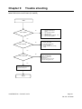
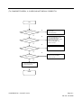
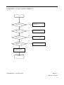
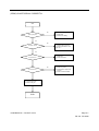
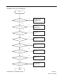
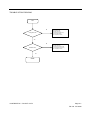
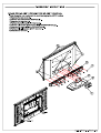
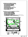
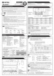
Service Manual
Model #: VIZIO GV47L FHDTV10A
V, Inc
320A Kalmus Drive Costa Mesa, CA 92626
TEL : +714-668-0588 FAX :+714-668-9099
Top
Confidential
Table of Contents
CONTENTS
PAGE
Sections
1. Features
1-1
2. Specifications
2-1
3. On Screen Display
3-1
4. Factory Preset Timings
4-1
5. Pin Assignment
5-1
6. Main Board I/O Connections
6-1
7. Theory of Circuit Operation
7-1
8. Waveforms
8-1
9. Trouble Shooting
9-1
10. Block Diagram
10-1
11. Spare parts list
11-1
12. Complete Parts List (GV47L FHDTV10A)
12-1
Appendix
1. Main Board Circuit Diagram
2. Main Board PCB Layout
3. Assembly Explosion Drawing
Block Diagram
VIZIO GV47L FHDTV10A Service Manual
VINC
Service Manual
VIZIO GV47L FHDTV10A
COPYRIGHT © 2000 V, INC. ALL RIGHTS RESERVED.
IBM and IBM products are registered trademarks of International Business Machines
Corporation.
Macintosh and Power Macintosh are registered trademarks of Apple Computer, Inc.
VINC and VINC products are registered trademarks of V, Inc.
VESA, EDID, DPMS and DDC are registered trademarks of Video Electronics Standards
Association (VESA).
Energy Star is a registered trademark of the US Environmental Protection Agency (EPA).
No part of this document may be copied, reproduced or transmitted by any means for any
purpose without prior written permission from VINC.
FCC INFORMATION
This equipment has been tested and found to comply with the limits of a Class B digital device,
pursuant to part 15 of the FCC Rules. These limits are designed to provide reasonable
protection against harmful interference in a residential installation. This equipment generates,
uses and can radiate radio frequency energy, and if not installed and used in accordance with
the instructions, may cause harmful interference to radio communications. However, there is
no guarantee that the interference will not occur in a particular installation. If this equipment
does cause unacceptable interference to radio or television reception, which can be
determined by turning the equipment off and on, the user is encouraged to try to correct the
interference by one or more of the following measures -- reorient or relocate the receiving
antenna; increase the separation between equipment and receiver; or connect the into an
outlet on a circuit different from that to which the receiver is connected.
FCC WARNING
To assure continued FCC compliance, the user must use a grounded power supply cord and
the provided shielded video interface cable with bonded ferrite cores. Also, any unauthorized
changes or modifications to Amtrak products will void the user’s authority to operate this
device. Thus VINC Will not be held responsible for the product and its safety.
CE CERTIFICATION
This device complies with the requirements of the EEC directive 89/336/EEC with regard to
“Electromagnetic compatibility.”
SAFETY CAUTION
Use a power cable that is properly grounded. Always use the AC cords as follows – USA (UL);
Canada (CSA); Germany (VDE); Switzerland (SEV); Britain (BASEC/BS); Japan (Electric
Appliance Control Act); or an AC cord that meets the local safety standards.
VIZIO GV47L FHDTV10A Service Manual
Chapter 1
Features
1. High resolution 1920 x 1080 with wide screen.
2. Built-in digital HDTV and standard TV combination TV tuner.
3. All TV formats supported (1080i, 720p, 480 p and 480i).
4. Computer Monitor (RGB): up to1360 x 768 (H x V).
5. Wall mounting capable with and without speakers.
6. 2.1 virtual surround sound with 20W subwoofer.
7. Dual HDMI (High Definition Multimedia Interface).
8. Independent Red, Green and Blue adjustment in TV, Video, HDMI and VGA
for user fine tuning of color temperature with reset.
9. Power saving to reduce consumption power to less than 3W.
10. Zero Bright Pixel.
11. PIP, POP, CC, V-Chip, 3D Comb Filter, Zoom, Freeze, 3:2 Reverse
Pull-down, ATSC, with 8VSB & QAM demodulation, with MPEG-2 decoding,
NTSC Video decoding via RF (Antenna, Cable or Satellite) or Video (CVBS,
S-Video or Component), Progressive Scan Video via Component YPbPr,
VGA or HDMI, HDTV via HDMI or Component YPbPr,
CONFIDENTIAL – DO NOT COPY
Page 1-1
File No. SG-0208
Chapter 2
Specification
1. TFT-LCD CHARACTERISTICS
Type: 47.0” WUXGA TFT LCD
Size: 47 inch
Display Size: 46.96” diagonal
Outline Dimension: 1096 mm (H) x 640 mm (V) x 51 mm (D) (Typ.)
Pixel Pitch: 0.5415mm (H) x 0.5415mm (V)
Pixel Format: 1920 horiz. By 1080 vert. Pixels RGB strip arrangement
Contrast ratio: 800:1(Typ.), 1,600:1 with DCR
Luminance, White: 500 cd/m2 (Typ.)
Display Operating Mode: normally Black
Surface Treatment: Hard Coating (3H), Anti-glare treatment of the front polarizer.
2. OPTICAL CHARACTERISTICS
Viewing Angle (CR>10)
Left: 89°typ.
Right: 89°typ.
Top: 89°typ.
Bottom: 89°typ.
3. SIGNAL (Refer to the Timing Chart)
Sync Signal
1) Type: LVDS
2) Input Voltage Level: 100~240 Vac, 50/ 60 Hz
4. Input Connectors
RJ11, D-SUB15PIN (MINI, 3rows), Headphone, HDMIX2, RCAX2 (component), RCAX2
(AUDIO in), RCAX2 (composite), RCAX2 (AUDIO in), S-Video, Tuner
5. POWER SUPPLY
Power Consumption: 400W MAX
Power OFF: 3W MAX
CONFIDENTIAL – DO NOT COPY
Page 2-1
File No. SG-0208
6.Speaker
Output 10W (max) X2, Sub woofer 20W X1
7. ENVIRONMENT
7-1. Operating Temperature: 0c~35c (Ambient)
7-2. Operating Humidity: Ta= 35 °C, 90%RH (Non-condensing)
7-3. Operating Altitude: 0 - 14,000 feet (4267.2m)(Non-Operating)
8. DIMENSIONS (Physical dimension)
Width: 1131 mm.
Depth: 270 mm
Height: 798 mm
9. WEIGHT (Physical weight)
a. Net: 40.3 +/-0.5kgs
b. Gross: 47.3+/-0.5kgs
9-1. MOUNTING PRECAUTIONS
(1) You must mount a module using holes arranged in four corners or four sides.
(2) You should consider the mounting structure so that uneven force (ex. Twisted stress) is not
applied to the module. And the case on which a module is mounted should have sufficient
strength so that external force is not transmitted directly to the module.
(3) Please attach the surface transparent protective plate to the surface in order to protect the
polarizer. Transparent protective plate should have sufficient strength in order to the resist
external force.
(4) You should adopt radiation structure to satisfy the temperature specification.
(5) Acetic acid type and chlorine type materials for the cover case are not desirable because the
former generates corrosive gas of attacking the polarizer at high temperature and the latter
causes circuit break by electro-chemical reaction.
CONFIDENTIAL – DO NOT COPY
Page 2-2
File No. SG-0208
(6) Do not touch, push or rub the exposed polarizes with glass, tweezers or anything harder than
HB pencil lead. And please do not rub with dust clothes with chemical treatment.
Do not touch the surface of polarizer for bare hand or greasy cloth.(Some cosmetics are
detrimental to the polarizer.)
(7) When the surface becomes dusty, please wipe gently with absorbent cotton or other soft
materials like chamois soaks with petroleum benzene. Normal-hexane is recommended for
cleaning the adhesives used to attach front / rear polarizers. Do not use acetone, toluene and
alcohol because they cause chemical damage to the polarizer.
(8) Wipe off saliva or water drops as soon as possible. Their long time contact with polarizer
causes deformations and color fading.
(9) Do not open the case because inside circuits do not have sufficient strength.
9-2. OPERATING PRECAUTIONS
(1) The spike noise causes the mis-operation of circuits. It should be lower than following
voltage :
V=±200mV(Over and under shoot voltage)
(2) Response time depends on the temperature. (In lower temperature, it becomes longer.)
(3) Brightness depends on the temperature. (In lower temperature, it becomes lower.)And in
lower temperature, response time (required time that brightness is stable after turned on)
becomes longer.
(4) Be careful for condensation at sudden temperature change. Condensation makes damage to
polarizer or electrical contacted parts. And after fading condensation, smear or spot will occur.
(5) When fixed patterns are displayed for a long time, remnant image is likely to occur.
(6) Module has high frequency circuits. System manufacturers shall do sufficient suppression to
the electromagnetic interference. Grounding and shielding methods may be important to
minimize the interference.
CONFIDENTIAL – DO NOT COPY
Page 2-3
File No. SG-0208
9-3. HANDLING PRECAUTIONS FOR PROTECTION
(1) The protection film is attached to the bezel with a small masking tape. When the protection
film is peeled off, static electricity is generated between the film and polarizer. This should be
peeled off slowly and carefully by people who are electrically grounded and with well
ion-blown equipment or in such a condition, etc.
(2) When the module with protection film attached is stored for a long time, sometimes there
remains a very small amount of glue still on the bezel after the protection film is peeled off.
(3) You can remove the glue easily. When the glue remains on the bezel surface or its vestige is
recognized, please wipe them off with absorbent cotton waste or other soft material like
chamois soaked with normal-hexane.
CONFIDENTIAL – DO NOT COPY
Page 2-4
File No. SG-0208
Chapter 3
On Screen Display
Main unit button
POWER
SOURCE
CH +
CH VOL +
VOL MENU
TV Source
A. Picture Adjust:
a. Picture Mode (Standard/Movie /Game /Custom)
b. Backlight (0~100)
c. Contrast (0~100)
d. Brightness (0~100)
e. Color (saturation)(0~100)
f. Tint (hue) (0~100)
g. Sharpness (0~7)
h. Color Temperature (Cool/Normal/Warm/Custom)
i. Advanced Picture Adjust
B. Audio Adjust:
a. Volume (0~100)
b. Bass (0~100)
c. Treble (0~100)
d. Balance (-50~+50)
e. Surround (ON/OFF)
f. Speakers (ON/OFF)
CONFIDENTIAL – DO NOT COPY
Page 3-1
File No. SG-0208
C. Special Features:
a. Language (English/Français/Espaňol)
b. Sleep Timer (OFF/30Min/60Min/90Min/120Min)
c. Analog CC (OFF/CC1~4/TT1~4)
d. Digital CC (OFF/CC1~4/Service1~6)
e. Digital CC Style
f. PIP Position (TL/TC/TR/ML/MR/BL/BC/BR)
g. Rest All Settings
D. TV Tuner Setup:
a. Tuner Mode (Cable/Air)
b. Auto Search
c. Skip Channel
d. Digital Audio Out (PCM/Dolby Digital)
e. Time Zone
(Eastern/Indiana/Central/Mountain/Arizona/Pacific/Alaska/Hawaii)
f. Daylight Saving (ON/OFF)
E. Parental Control:
a. Parental Lock Enable (ON/OFF)
b. TV Rating
c. Movie Rating
d. Block Unrated TV (NO/YES)
e. Access Code Edit
RGB Mode
A. Picture Adjust:
a. Auto Adjust
b. Backlight (0~100)
c. Contrast (0~100)
d. Brightness (0~100)
e. Color Temperature (9300/6500/Custom)
f. H-Size (0~255)
g. Horizontal Shift (0~255)
h. Vertical Shift (0~63)
i. Fine Tune (0~31)
CONFIDENTIAL – DO NOT COPY
Page 3-2
File No. SG-0208
B. Audio Adjust:
a. Volume (0~100)
b. Bass (0~100)
c. Treble (0~100)
d. Balance (-50~+50)
e. Surround (ON/OFF)
f. Speakers (ON/OFF)
C. Special Features:
a. Language (English/Français/Espaňol)
b. Sleep Timer (OFF/30Min/60Min/90Min/120Min)
c. PIP Position (TL/TC/TR/ML/MR/BL/BC/BR)
d. Rest All Settings
AV / SV / COMPONENT MODE
A. Picture Adjust:
a. Picture Mode (Standard/Movie /Game /Custom)
b. Backlight (0~100)
c. Contrast (0~100)
d. Brightness (0~100)
e. Color (saturation) (0~100)
f. Tint (hue) (-50~+50)
g. Sharpness (0~7)
h. Color Temperature (Cool/Normal/Warm/Custom)
i. Advanced Picture Adjust
B. Audio Adjust:
a. Volume (0~100)
b. Bass (0~100)
c. Treble (0~100)
d. Balance (-50~+50)
e. Surround (ON/OFF)
f. Speakers (ON/OFF)
CONFIDENTIAL – DO NOT COPY
Page 3-3
File No. SG-0208
C. Special Features:
a. Language (English/Français/Espaňol)
b. Sleep Timer (OFF/30Min/60Min/90Min/120Min)
c. Analog CC (OFF/CC1~4/TT1~4)
d. PIP Position (TL/TC/TR/ML/MR/BL/BC/BR)
e. Rest All Settings
D. Parental Control:
a. Parental Lock Enable (ON/OFF)
b. TV Rating
c. Move Rating
d. Block Unrated TV (NO/YES)
e. Access Code Edit
HDMI MODE:
A. Picture Adjust:
a. Picture Mode (Standard/Movie /Game /Custom)
b. Backlight (0~100)
c. Contrast (0~100)
d. Brightness (0~100)
e. Color (saturation) (0~100)
f. Tint (hue) (-50~+50)
g. Sharpness (0~7)
h. Color Temperature (Cool/Normal/Warm/Custom)
i. Advanced Picture Adjust
B. Audio Adjust:
a. Volume (0~100)
b. Bass (0~100)
c. Treble (0~100)
d. Balance (0~100)
e. Surround (ON/OFF)
f. Speakers (ON/OFF)
CONFIDENTIAL – DO NOT COPY
Page 3-4
File No. SG-0208
C. Special Features:
a. Language (English/Français/Espaňol)
b. Sleep Timer (OFF/30Min/60Min/90Min/120Min)
c. PIP Position (TL/TC/TR/ML/MR/BL/BC/BR)
d. Rest All Settings
CONFIDENTIAL – DO NOT COPY
Page 3-5
File No. SG-0208
Chapter 9
Trouble shooting
MONITOR DISPLAY NOTHING (PC MODE)
Start
N0
LED is lighted
1.
2.
3.
4.
5.
Is Power board output
+5V?
Is J7 connector good?
Is DC-DC OK?
Is U6&U4 (3.3V) working
Is J6 connector good?
ok?
Yes
N0
LED is lighting?
It is in power saving
1. Check video cable
2. Is the timing supported?
3. Check sync input
4. Check VGASOG rout if analog
(SOG)
Yes
N0
U11 no data out?
It means data to LVDS
1.Is J5 connecting OK?
2.Check J7 +5V&+12V
3.Is panel ok?
4. Check P3 D-sub Input correct
5. Check analog input route
Yes
1.Chcak J5 Connect is good?
2.Is panel working ok?
END
CONFIDENTIAL – DO NOT COPY
Page 9-1
File No. SG-0208
(TV, COMPOSITE VIDEO1, 2, S-VIDEO) IS NOT DISPLAY CORRECTLY
Start
N0
1.Check video
2.Check DVD player
Input signal good?
Yes
N0
U11 input correct?
1.Check P2&P12 signal
2.Check signal between P2 and
U11 (IF AV1/AV2 mode)
3.Check Tuner &U11 (IF TV mode)
4.Check P12 (IF S-Video)
5.Check U11 POWER +3.3V
6.Check Y1 is OK?
Yes
N0
1.Check signal between U20 and
U9
U11 output correct?
Yes
N0
LVDS output correct?
1.Check LVDS LINE
2.Check U11 clock (27MHz)
3.Check U11 power
Yes
1.Chcak J5 Connect is good?
2.Is panel working ok?
END
CONFIDENTIAL – DO NOT COPY
Page 9-2
File No. SG-0208
(COMPONENT1, 2) IS NOT DISPLAY CORRECTLY
Start
N0
1.Check video
2.Check host’s setting
Input signal good?
Yes
N0
1.Check signal between P4
2.Check power 12V& 5v
P4 input correct?
Yes
N0
1.Check signal between U11&P4
2.Check U11 Clock (27MHZ)
U11 input correct?
Yes
N0
LVDS output correct ?
1.Check U11
2.Check U11 power 3.3V&1.25v&1.8v
Yes
1.Is J5 connected good?
2.Is panel working ok?
END
CONFIDENTIAL – DO NOT COPY
Page 9-3
File No. SG-0208
(HDMI) IS NOT DISPLAY CORRECTLY
Start
N0
1.Check video
2.Check host’s setting
Input signal good?
Yes
N0
1.Check p10&p11 connect
2.Check signal between U31
and U19
U31 input correct?
Yes
1.Check U33
2.Check U32 & U34
U11 no data out ?
N0
U11 no data out ?
1.Check U11 power
2.Check between signal U19
and U11
3.Check U19 clock 27MHZ
1.Is J6 connected good?
2.Is panel working ok?
END
CONFIDENTIAL – DO NOT COPY
Page 9-4
File No. SG-0208
TROUBLE OF DC-DC CONVERTER
Start
N0
J7 PIN10,11,12
The voltage is about + 5V
1.Check power board
2.Check power cable
connection J7
Yes
N0
J7 PIN 2,3,4
The voltage is about + 12V while
power switch on
1.J7 connection good
2.Check J7 Pin1 is up to 3V?
3.Check power board
Yes
N0
The voltage is about +5V while
power switch on
1. Check U11 GPIO_7 Pin
U1 pin 5 6 7 8
Yes
N0
The voltage is about +3.3V
1.Check U4
U4 pin2
Yes
N0
U6 pin 2
Yes
The voltage is about +3.3V
1.Check U6
N0
The voltage is about +1.8V while
power switch on
1.Check U5
U5 pin2
Yes
N0
U8 pin2
The voltage is about +3.3V
while power switch on
1.Check U8
U7&U8&U10 pin2
The voltage is about +1.8V
while power switch on
1.Check U7&U8&U10
END
CONFIDENTIAL – DO NOT COPY
Page 9-5
File No. SG-0208
TROUBLE OF DDC READING
Start
N0
Support DDC1/2B
1.Analog cable ok?
2.Check signal (U20 to P3)
3.Check U20 Voltage
4.Is compliant protocol?
Analog DDC OK?
Yes
N0
HDMIDDC OK?
Support DDC1/2B
1.Analog cable ok?
2.Check signal (U32 to P10)
3. Check signal (U34 to P11)
4.Is compliant protocol?
Yes
END
CONFIDENTIAL – DO NOT COPY
Page 9-6
File No. SG-0208