1
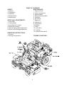
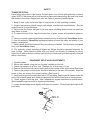
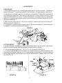
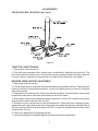
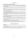
Operator’s Manual for
MODELS: ZKW42171
ZKW42172
ZKW42182
Professional Quality Lawn Care Equipment
since 1945
Thank you for buying a YAZOO/KEES ZT Max! Before operating your new mower, read,
understand and follow the important safety instructions and the other instructions contained in this manual. Lawnmowers and all power equipment, can be potentially dangerous if used improperly. SAFETY REQUIRES GOOD JUDGEMENT, CAREFUL USE IN
ACCORDANCE WITH INSTRUCTIONS AND COMMON SENSE.
MANUAL 105288 REV.04(10/03/02)
Congratulations on the purchase of your Yazoo/Kees mower. This manual has been prepared for the owners and operators of the ZT MAX™ 42" and 48" commercial mowers. Read,
understand and follow the saftey and operating instructions.
! WARNING
Failure to follow cautious operating practices can result in serious injury to the operator or
other persons. The owner must understand these instructions, and must allow only trained
persons who understand these instructions to operate the mower. Each person operating
the mower must be of sound mind and body and must not be under the influence of any mind
altering substance.
If you have any questions pertaining to your mower contact your dealer.
! CAUTION
1. Keep all shields, guards and safety devices in place and in proper working condition.
2. Stop engine and remove spark plug wires or remove key before adjusting, servicing, or
performing maintenance.
WARNING: Engine exhaust, some of it’s constituents, and certain vehicle componets
contain or emit chemicals known to the State of California to cause cancer and birth
defects or other reproductive harm.
WARNING: Battery posts, terminals and related accessories contain lead and lead
compounds, chemicals known to the State of California to cause cancer and
birth defects or other reproductive harm. Wash hands after handling.
Continuous dedication to improve our products require that specifications and design are
subject to change without notice.
2
TABLE OF CONTENTS
MAINTENANCE:
1. Engine oil level
2. Pump compartment
3. Mower blades
4. Safety interlock system
5. Hardware
6. Air cleaner
SETUP AND ADJUSTMENTS:
7. Engine oil
1. Park brake
8. Hydraulic oil
2. Cutting height
9. Tire presure
3. Front deck belt routing
10. Battery
4.Throttle lever tension
11. Belts
5. Reverse spring detent adjustment
12. Lubrication
6. Motion control linkage adjustment
13. Fuel filter
14. Hydraulic filter and oil
OPERATING INSTRUCTIONS:
1. Controls
2. Starting and operation
TROUBLE SHOOTING:
SAFETY:
1. Training
2. Preparation
3. Operation
4. Transportation
5. Maintenance
3
SAFETY
TRAINING:
1. Read this manual carefully and question your dealer if something is not clear.
2. Be thoroughly familiar with the controls and proper use of the equipment.
3. Never allow children, teenagers, or people unfamiliar with these instructions to use the
mower.
4. Do not mow while people, particularly children, or pets are nearby.
PREPARATION:
1. The use of personal protective equipment such as (but not limited to) protection for the
eyes, ears, feet and head is recommended.
2. Never operate the mower without proper guards, covers, safety switches and devices in
place and properly functioning. Inspect these items daily for their condition and proper operation. If the condition or operation of any of these devices is questionable they must be
replaced or repaired before using the mower.
3. Thoroughly inspect the area to be mowed and remove all stones, sticks, wire and other
debris that may be thrown by the mower. Also note or mark other obstacles such as holes,
stumps, etc..
4. Do not operate the mower when barefoot or wearing open shoes. Always wear substantial
footwear and long pants.
5. Fill gas tank(s) before starting mower. DO NOT SMOKE near gasoline containers. Do not
fill gas tank indoors or when engine is hot or running. Clean off any spilled gasoline before
starting the mower.
OPERATION:
1. Mow only in daylight or good artificial light.
2. Do not operate the mower in wet grass if possible.
3. Mow up and down slopes. Use extreme caution when mowing or turning on slopes.
Always turn to the downhill side. Do not mow excessively steep slopes ( mower may tip
over and cause injury or death ).
4. Use caution when backing up.
5. Stop the blades when crossing surfaces other than grass; or when traveling to and from
the area to be mowed.
6. Never operate the mower with defective, broken or excessively worn parts. Keep all
guards, shields, and safety devices in place and in proper working order.
7. Do not change the engine governor settings or over speed the engine. Operating the
engine at excessive speeds will increase the hazard of injury and can severely damage your
machine.
8. Keep hands, feet and clothing away from rotating parts when operating mower.
9. Stop the blades and engine and set park brake before leaving the operators position for
any reason.
10. Never make adjustments to the mower while engine and/or blades are running.
11. After striking a foreign object, stop mower and remove key. Inspect the mower for any
damage and repair it immediately before continuing to mow.
12. Never operate this equipment in an enclosed or confined area without proper ventilation
of the engine exhaust.
13. Do not allow any passengers to ride on the mower. It is designed for the operator only.
Keep others away from the mower when in operation.
4
SAFETY
TRANSPORTATION:
Use a heavy duty trailer to haul mower. Set park brake, turn off fuel valve and strap mower to
trailer. NOTE: Park brake will not hold mower in place when transporting. Be sure to tie down
the mower to the trailer. Always back onto the trailer to prevent possible tipover.
1. Keep all nuts, bolts and screws tight to keep mower in safe operating condition.
2. Engine maintenance should comply with engine manufactures specifications. See the
engine manual for specifications.
3. Never store the mower with gas in the tank inside a building where fumes can reach an
open flame or spark.
4. To reduce the risk of fire, keep the mower free of grass, leaves and excessive grease or
oil.
5. Have your mower inspected and serviced each year by an authorized Yazoo/Kees dealer.
6. Use only authentic Yazoo/Kees replacement parts to insure the safety and quality of your
mower is maintained.
7. Safety decals should be replaced if they are missing or illegible. Decals can be purchased
from your Yazoo/Kees dealer.
8. The hydraulic system including all hoses and fittings should be checked frequently for
wear or leaks. Never check for leaks with your hands, use a piece of cardboard or wood.
Hydraulic oil under pressure could be injected into your body and must be surgically removed
within a few hours.
EQUIPMENT SETUP AND ADJUSTMENTS
1. Uncrate mower
2. Mount drive wheels using the four lug nuts installed on the hub.
3. Check tire pressure in all four tires. Pressure for all four tires is 15 psi
4. Remove the motion control levers and install on the outside of the control arms (See figure
1). Tabs on the motion control levers should be directed to the rear of the mower. Align the
levers so they are even in the neutral position. (See figure 6)
5. Install seat lanyard to the seat frame with 5/16" hardware. Seat lanyard is located under the
seat in the hydraulic pump area. Attach the lanyard to the left front seat stud on the seat frame.
6. Check engine oil with dip stick. Add if needed per engine manufactures specifications.
(See Kawasaki engine manual for engine specifications.)
7. Loosen the discharge chute slightly and lower into position. Chute should be snug but still
pivot freely.
Figure 1
5
ADJUSTMENTS
PARK BRAKE:
1. Stop engine and remove key. While the park brake lever”A” is in the on postion. The distance
between the swivel”C” and the bolt head”B” should be 3/8” to 1/2” approximately.(See Fig. 2)
2. If adjustment is needed, using two 1/2” wrenchs, loosen the nut”F” above the turnbuckle”G”
while holding the turnbuckle”G” from turning. After the nut”F” is loose and out of the way. While
holding the bolt head”B” from turning. Turn the turnbuckle”G” the proper direction to lengthen the
distance or to shorten the distance. After the proper distance is obtained retighten the nut”F”
against the turnbuckle”G”.
3. While the park brake lever”A” is still in the on postion, measure the lenght of the spring”D”.
Should measure 2”.(See Fig. 2)
4. If adjustment is needed loosen or tighten the nut”E” below the spring”D”. While holding the
turnbuckle”G” to keep the assembly from turning.
FIGURE 2
CUTTING HEIGHT:
1. Before changing cutting heights make sure the blades are off, key switch is off, and the park
brake is on.(Never change the cutting heights with the mower still running.)
2. The cutting height ranges from 1 1/2” to 5.0” in 1/2” increments.(See Fig. 3a)
3. To change cutting heights pull the hairpins out of the bent arm pins. While hanging on to the
deck handle, pull the bent arm pins out of the deck hangers, front and back. Choose the desired
cutting height position and relocate bent arm pins and the hairpins. Repeat steps on the other
side.(See Fig. 3b)
FIGURE 3a
FIGURE 3b
6
ADJUSTMENTS
FRONT DECK BELT ROUTING: (See Fig. 4)
Figure 4
THROTTLE LEVER TENSION:
1. Stop engine and remove key.
2. If throttle lever becomes loose, tension may be adjusted by tightening the pivot bolt. The
pivot bolt holds the throttle arm to the throttle mounting bracket which is located under the
console. Access is gained by removing the foot plate and the kick plate. See page 3.
REVERSE SPRING DETENT ADJUSTMENT:
1. Stop engine and remove key.
2. Pull the motion control lever back to the reverse position and release the lever. When the lever
stops it should be in line with the neutral slot, so you can rotate the lever out with out hitting the
side of the console.
3. If adjustment is needed put the seat in the rear slide position, tilt seat forward, remove seat
lanyard from seat frame, and rotate seat forward to rest on the frame.
4. On the back of the console where the spring is fastened. Loosen 3/8” nut and bolt enough to
allow the bolt to slide in the slot.(See Fig. 5a)
5. Rotate the motion control lever out into the neutral slot. While the lever is swung out pull it
against the back edge of the neutral slot. Holding the lever adjust the spring by sliding the bolt in
the slot to remove all the slop and retighten the 3/8” nut and bolt.(Repeat steps on other side if
needed.)(See Fig. 5a)
6. Check your adjustment by repeating step two.
7. If no more adjustment is needed refasten the seat lanyard to the seat frame.
7
Figure 5a
(Left side cut away view)
Figure 5b
(Left side cut away view)
8
ADJUSTMENTS
MOTION CONTROL LINKAGE ADJUSTMENT:
1. This adjustment must be made with the drive wheels rotating. Raise rear of the unit and
block it up so the wheels are free to rotate. CAUTION: Keep hands, feet and clothing away
from rotating tires.
2. Tilt seat forward and remove the seat lanyard from seat so the seat can rotate down onto the
frame. Make sure the seat is adjusted toward the rear of the unit so it clears the controls on the
console.
3. Place a 2x4 board approximatly 10 to 12 inches long between the foot plate and the center of
the seat to engage the seat safety switch. NOTE: You may want to cover the end of the 2x4 with
a rag to protect the seat from marring.
4. Loosen the nuts directly behind each ball joint on both rods that connect the pump arm to the
motion control assemblies. (See Fig 5b )
5. Start the engine. The park brake must be engaged and the motion control levers must be in the
neutral slot (See figure 6 page10) to start the engine. Run engine at approximately 1/2 throttle.
6. Release park brake to allow wheels to rotate. CAUTION: Keep hands, feet and clothing away
from rotating tires.
7. Begin with either side and put the motion control lever into the neutral position. Adjust the
motion control linkage by rotating the double nuts on the rod in the proper direction until the
wheel stops rotating (See Fig 5b ).
Move the motion control lever forward then into the neutral position and place it into the
neutral slot. The wheel must be stopped completely at this point. Now do the same in reverse
and release the lever. The lever should return to neutral on its own. If not see reverse spring
detent adjustment section.
8. Run engine at full throttle to make sure wheels do not rotate. Readjust if any rotation occurs.
9. Repeat on the opposite side and tighten nuts against ball joints.
10. Remove the 2x4 board and make sure the seat wiring is connected to the wiring harness.
WARNING: Seat must be connected for safety interlock system to properly function.
OPERATING INSTRUCTIONS
CONTROLS:
1. Be thoroughly familiar with all controls their function and how to operate them before
operating the mower.
2. Motion control levers located on each side of the console control direction of movement.
The left lever controls the flow of oil from the left hydro pump to the left wheel motor. The right
lever controls the flow of oil from the right hydro pump to the right wheel motor.
9
OPERATING INSTRUCTIONS
NOTE: To begin motion the operator must be in the seat and the brake disengaged before
the levers can be moved from the neutral slots or the engine will kill.
By moving the levers an equal amount forward or back the mower will move in a straight line
in that direction.
Movement of the right lever forward will cause the right wheel to rotate in a forward direction.
Movement of the left lever forward will cause the left wheel to rotate in a forward direction. To
stop forward travel pull levers back into the neutral position.
To turn right while moving in a forward direction pull the right lever back towards the neutral
position, this will slow the right wheel and cause the mower to turn in that direction.
To turn left while moving in forward direction pull the left lever back towards the neutral
position, this will slow the left wheel and cause the mower to turn in that direction.
To zero turn pull one lever back beyond neutral while holding the other slightly ahead of
neutral. NOTE: The direction of the zero turn will be determined by which lever is pulled back
beyond neutral. Thus, left lever back, left turn and opposite for right turn. Use caution when
using this maneuver unit can spin very rapidly if one lever is positioned too much
ahead of the other.
3. Blade engagement switch: Located on the console. Pull up on switch to engage blades,
push down to turn blades off. See page 3
4. Choke control: Located on the console. Push the throttle control all the way forward. Use when
starting cold engine do not run choke when engine is warm. See page 3
5. Throttle control: Located on the console. Used to control engine RPM. See page 3
6. Park brake: Located at the left end of the console. Pull lever back to engage the park
brake, push lever forward to release brake. NOTE: Use tie downs when transporting unit, the
park brake is not enough to hold the unit in place in this situation. See page 3
7. Key switch: Located on the console. The operator must be in the seat, park brake on,
motion control levers out in the neutral slots and blade switch off before engine will start. See
page 3
8. Fuel shut off valve: Located on the front of console at the top of the kick plate. The valve
has three positions left tank, right tank and straight down is the off position. See page 3
9. Pump release valves: Located at the back left corner of the pumps. Used to release the system so unit may be moved by hand when not running. Tilt the seat up to gain access to the pumps.
Rotate valve towards the front of the unit to release the system using a 5/8 wrench. NOTE: Only
rotate about a 1/4 of a turn to release system.
10
OPERATING INSTRUCTIONS
STARTING AND OPERATION:
1. Operator must be sitting in the seat. Engage park brake, blades off and place the motion
control levers in the neutral slots. (See figure 6)
2. Adjust throttle to choke (if needed) turn key and release as soon as engine starts, and adjust
1/2 throttle.
3. Release park brake.
4. Close motion control levers.
5. Engage blades and set RPM to maximum, but not choked. NOTE: Be sure all persons are
clear of area before engaging the blades. To prolong spindle bearing and belt life engage and
disengage blades at approximately 1\2 throttle
Figure 6 (Right side)
MAINTENANCE
1. Engine oil level: Check daily with engine cold and on a flat surface. Remove the dipstick and
wipe clean. Reinsert the dipstick all the way,but do not screw down. Remove the dipstick and
check oil level. If oil level is low add oil. Use engine manufacturers specs for type of oil.
2. Pump drive belt compartment: Stop engine and remove key. Tilt seat forward and clean all
debris from inside. NOTE: Cleaning may need to be done more frequently in dry conditions.
3. Mower blades: Stop engine and remove key. Inspect blades and sharpen or replace as needed.
Check daily or more often if needed. The machine requires more power with dull blades and
gives a poor cut. If blades get bent, replace them. Blades shouldn’t have any notches from
hitting objects. The air foil on top of the blade should be sufficient to raise the grass for cutting. If
blades are in good condition, sharpen at an angle of 22 to 28 degrees about 2-1/2 inches in from
the tips. Note: After sharpening, check blades for proper balance, if needed correct balance to
prevent excessive vibration.
4. Safety interlock system: Check daily and never operate the mower if this system is not
functioning properly. The starter should crank only when the operator is in the seat, the park
brake set, blades off and the motion control levers in the neutral slots. If the mower starts with
any of these controls on or in an operating position, turn the mower off and repair the system
immediately.
11
MAINTENANCE
5. Hardware: Stop engine and remove key thoroughly inspect the entire machine for any
missing or loose hardware. Check daily.
6. Air cleaner: Stop engine and remove key. Remove plastic cover and loosen wingnut on the
air cleaner. Remove the foam pre-cleaner and wash or replace if needed. Inspect paper filter
and replace if dirty. Check every 25 hours, daily if in very dirty conditions. Fuel efficiency,
engine RPM, and available power goes down rapidly if the air filter is dirty. Prolonged effects
could damage the engine.
7. Engine oil: Change oil to manufacturers specifications. Stop engine and remove key. Drain
oil when engine is warm. Thoroughly clean around cap before removing. Remove oil
drain cap from the right side of engine block and replace drain cap. Remove oil filter and replace. Put a light coat of clean oil on the filter gasket before installing. Fill engine with oil using
manufacturers specs, see Kawasaki owner’s manual. Start engine and idle slowly to allow the oil
to recoat the interior of the engine and then inspect for leaks.
8. Hydraulic oil: Check daily. Stop engine and tilt seat forward.Thoroughly clean around
cap. Remove cap. Oil level should be even with the top of the baffle in the tank. If not, add oil.
NOTE: Use only 20w - 50 motor oil.
9. Tire pressure: Check every 25 to 50 hours. All four tires require 15 psi.
10. Battery: Maintance free
11. Belts: Check every 25 hours. Stop engine and remove key. Check the condition of all
belts.
12. Lubrication (every 25 hours):
Front caster pivots
Front wheels
Motion Control Brackets Left and Right
Pump idler pivot
Deck idler pivot
(Clean grease zerk thoroughly before greasing)
12
MAINTENANCE
13. Fuel filter: Replace annually or as needed.
14. Hydraulic filter and oil: Change every 500 hours or yearly. Stop engine and remove key.
Clean around the filter and the drain plug on the bottom side of the tank. Remove the filter and
allow any oil to drain from the filter head. Then replace with new filter. Use only Yazoo/Kees p/n
102606, filter which has a bypass valve and the correct micron filter. Remove drain plug under
hydraulic tank and allow tank to drain, reinstall drain plug. Fill tank with 20w - 50 motor oil to the
top of the baffle in the tank and replace cap. Block up the rear of unit until wheels will rotate freely
and start engine at a slow idle, move the motion control levers forward and run for several minutes. Stop engine and recheck oil level. If wheels don’t response an air lock has occured within
the hydraulic system. Bleed air from lines, or let stand overnight to allow the air time to dissipate
out of the oil. Retry responses & check the oil level. Note: Serious damage to the pumps and
wheel motors can occur if the system is ran with an air lock.
13
TROUBLE SHOOTING
PROBLEM
POSSIBLE CAUSES
Engine won’t start
1. Blade switch on.
2. Drive levers not in the neutral slots.
3. Operator not in seat.
4. Park brake disengaged.
5. Dead battery or cable off.
....(Ignition switch left on)
6. Fuel valve closed or in the wrong position.
7. No fuel.
8. Spark plug wires off.
9. Bad spark plugs.
Mower will not move
or moves slowly or hard
1. Park brake on.
2. Pump bypass valves open.
3. Pump drive belt loose or off.
4. Hydraulic system failure.
5. Air in the hydraulic system.
Blades won’t engage
1. Blade belt off of pulleys.
2. Clutch unhooked from harness.
3. Blade switch failure.
4. Fuse burnt out.
Uneven cut
1. Tire pressure uneven. (15 psi all tires)
2. Blades bent (check tip to tip one blade thickness)
3. Air foil of blade worn or bent.
Cut is ragged
1. Blades dull.
2. Ground speed too fast.
3. Grass accumulation under deck.
Mower moves when
in neutral position
1. Motion control linkage out of adjustment.
2. Pump arms loose or out of adjustment.
3. Park brake out of adjustment.
Mower pulls left or right
1. Tire pressure uneven.
2. Motion control linkage adjustment.
3. Soft terrian.
4. Slope too steep.
When a problem occurs, do not overlook the simple causes.
For example, no fuel or battery disconnected when the engine will not start.
14
WIRING DIAGRAM
15
SERVICE RECORD
DATE
DESCRIPTION OF WORK DONE
16
SERVICE DONE BY