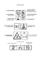
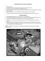
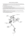
1
Operators Manual
Models:
KKFW48180
KKFW52180
KKFW52210
Please read these instructions carefully and make
sure you understand them before using the machine.
MANUAL NO. 107110 REV. IR (10/10/02)
Congratulations on the purchase of your Yazoo/Kees mower. This manual has been prepared
for the owners and operators of the Hydro Floating Deck 48" and 52" commercial mowers.
Read, understand and follow the saftey and operating instructions.
! WARNING
Failure to follow cautious operating practices can result in serious injury to the operator or other
persons. The owner must understand these instructions, and must allow only trained persons
who understand these instructions to operate the mower. Each person operating the mower
must be of sound mind and body and must not be under the influence of any mind altering substance.
If you have any questions pertaining to your mower contact your dealer.
! CAUTION
1. Keep all shields, guards and safety devices in place and in proper working condition.
2. Stop engine and remove spark plug wires or remove key before adjusting, servicing, or performing maintenance.
! WARNING !
THE ENGINE EXHAUST FROM
THIS PRODUCT CONTAINS
CHEMICALS KNOWN TO THE STATE
OF CALIFORNIA TO CAUSE
CANCER, BIRTH DEFECTS OR
OTHER REPRODUCTIVE HARM.
WARNING
Continuous dedication to improve our products require that specifications and design are subject to change without notice.
©Yazoo/Kees Power Equipment. All rights reserved.
Beatrice, NE • Printed in U.S.A.
2
TABLE OF CONTENTS
PAGE
SAFETY: ...................................................................... 4
Decals ..................................................................... 4
Training .................................................................... 5
Preparation .............................................................. 5
Operation ................................................................ 5
Transportation ......................................................... 6
Maintenance ............................................................ 6
SETUP AND ADJUSTMENTS: ................................... 7
Cutting height .......................................................... 7
Motion control linkage .............................................. 8
Reverse spring detent ............................................. 9
Mower Deck Leveling ............................................ 10
Blade belts ............................................................ 10
Pump belt .............................................................. 11
Safety interlock system ......................................... 11
OPERATING INSTRUCTIONS: ............................... 12
Controls ................................................................. 12
Starting and operation............................................ 12
MAINTENANCE: ....................................................... 14
Engine oil level ....................................................... 14
Pump belt .............................................................. 14
Mower blades ........................................................ 14
Safety interlock system ......................................... 14
Hardware ............................................................... 14
Air cleaner ............................................................. 14
Engine oil ............................................................... 14
Hydraulic oil ........................................................... 14
Tire presure ........................................................... 14
Belts ...................................................................... 14
Lubrication ............................................................. 14
Fuel filter ................................................................ 14
Hydraulic filter and oil ............................................ 15
Cutter housing ....................................................... 16
TROUBLE SHOOTING: ........................................... 17
WARRANTY: .............................................................. 19
3
SAFETY DECALS
SHUT OFF ENGINE AND
REMOVE KEY BEFORE
PERFOMORMING ANY
MAINTENANCE OR REPAIR
STAY A SAFE DISTANCE
FROM THE MACHINE
DO NOT OPEN OR REMOVE
SAFETY SHIELDS WHILE
ENGINE IS RUNING
RISK OF SEVERING OF
TOES OR FINGERS
MOWER BLADES
READ OPERATORS
MANUAL BEFORE
OPERATING MACHINE
RISK OF THROWN OR
FLYING OBJECTS
DO NOT OPEN OR REMOVE
SAFETY SHIELDS WHILE
ENGINE IS RUNING
RISK OF HAND AND
ARM ENTANGLEMENT
BELT DRIVE
RISK OF SEVERING OF
TOES OR FINGERS
MOWER BLADES
STAY A SAFE DISTANCE
FROM THE MACHINE
EXPLOSION HAZARD
KEEP AWAY FROM
OPEN FLAME
CHEMICAL BURN HAZARD
4
SAFETY
TRAINING:
1. Read this manual carefully and question your dealer if something is not clear.
2. Be thoroughly familiar with the controls and proper use of the equipment.
3. Never allow children, teenagers, or people unfamiliar with these instructions to use the
mower.
4. Do not mow while people, particularly children, or pets are nearby.
PREPARATION:
1. The use of personal protective equipment such as (but not limited to) protection for the
eyes, ears, feet and head is recommended.
2. Never operate the mower without proper guards, covers, safety switches and devices in
place and properly functioning. Inspect these items daily for their condition and proper operation. If the condition or operation of any of these devices is questionable they must be
replaced or repaired before using the mower.
3. Thoroughly inspect the area to be mowed and remove all stones, sticks, wire and other debris that may be thrown by the mower. Also note or mark other obstacles such as holes,
stumps, etc..
4. Do not operate the mower when barefoot or wearing open shoes. Always wear substantial
footwear and long pants.
5. Fill gas tank before starting mower. DO NOT SMOKE near gasoline containers. Do not fill
gas tank indoors or when engine is hot or running. Clean off any spilled gasoline before
starting the mower.
OPERATION:
1. Mow only in daylight or good artificial light.
2. Do not operate the mower in wet grass if possible.
3. Mow across slopes. Use extreme caution when mowing or turning on slopes. Always turn to
the downhill side. Do not mow excessively steep slopes ( mower may tip over and cause
injury or death ).
4. Use caution when backing up.
5. Stop the blades when crossing surfaces other than grass; or when traveling to and from the
area to be mowed.
6. Never operate the mower with defective, broken or excessively worn parts. Keep all guards,
shields, and safety devices in place and in proper working order.
7. Do not change the engine governor settings or over speed the engine. Operating the engine
at excessive speeds will increase the hazard of injury and can severely damage your ma
chine.
8. Keep hands, feet and clothing away from rotating parts when operating mower.
9. Stop the blades and engine before leaving the operators position for any reason.
10. Never make adjustments to the mower while engine and/or blades are running.
11. After striking a foreign object, stop mower and remove key. Inspect the mower for any dam
age and repair it immediately before continuing to mow.
12. Never operate this equipment in an enclosed or confined area without proper ventilation of
the engine exhaust.
13. Do not allow any passengers to ride on the mower. Keep others away from the mower when
in operation.
5
SAFETY
TRANSPORTATION:
Turn off fuel valve and strap mower to trailer.
MAINTENANCE:
1. Keep all nuts, bolts and screws tight to keep mower in safe operating condition.
2. Engine maintenance should comply with engine manufactures specifications. See the engine manual for specifications.
3. Never store the mower with gas in the tank inside a building where fumes can reach an open
flame or spark.
4. To reduce the risk of fire, keep the mower free of grass, leaves and excessive grease or oil.
5. Have your mower inspected and serviced each year by an authorized Yazoo/Kees dealer.
6. Use only authentic Yazoo/Kees replacement parts to insure the safety and quality of your
mower is maintained.
7. Safety decals should be replaced if they are missing or illegible. Decals can be purchased
from your Yazoo/Kees dealer.
8. The hydraulic system including all hoses and fittings should be checked frequently for wear or
leaks. Never check for leaks with your hands, use a piece of cardboard or wood. Hydraulic
oil under pressure could be injected into your body and must be surgically removed within a
few hours.
6
EQUIPMENT SETUP AND ADJUSTMENTS
1.
2.
3.
4.
Uncrate mower
Cut the plastic wire ties holding the operator presence levers down.
Check tire pressure in all four tires. (22 PSI in all tires)
Check engine oil with dipstick. Add if needed per engine manufactures specifications.(See
engine manual)
5. Check hydraulic oil level. Should be an 1.0” below the bottom of the fill tube.
6. Mount the discharge chute to the front deck using the fasteners provided on the deck.
1.
2.
3.
4.
CUTTING HEIGHT
Cutting height ranges from 1 1/4” to 4 3/4” in 1/4” increments.
Cutting height is changed by pushing the foot pedal (Figure 1) down until the transport lock
lever securely latches into the slot on the top surface of the height plate.
At this time, move the pin in the height plate to the desired cutting position and reinsert
hairpin.
After the pin is placed in the desired hole, press down on the foot pedal and remove the
transport lock lever from the slot. Gently remove pressure from the foot lever allowing the lift
arm to contact the pin in the height plate.
NOTE: To achive the best quality cut, the blades should be level with the ground or slighty
tipped forward.
TRANSPORT
LOCK LEVER
HEIGHT PLATE
PIN
FOOT PEDAL
FIGURE 1
7
MOTION CONTROL ADJUSTMENT
1. This adjustment must be made with the drive wheels rotating. Raise rear of the unit and
block it up so the wheels are free to rotate. CAUTION: keep hands, feet and clothing away
from rotating tires.
2. With the ground speed lever in neutral or stop position, start the engine.
3. The thumb latches should be unlocked.
4. Turn the adjusting nut the proper direction until the wheel stops rotating. This is your neutral
position, repeat on the other side. (See Figure 2.)
5. After the neutral position is adjusted. You will need to readjust the short linkage. (See Figure 2.)
6. Remove the two hairpins, swing the linkage out of the control lever and the thumb latch. See
Figure 2.)
7. Turn the short linkage the proper direction in the swivel, so that when the thumb latch is
engaged the wheel does not turn (or it is in neutral).
8. After these adjustments have been made it will be necessary to adjust the reverse detent.
(See reverse spring detent adjustment).
THUMB LATCH
SHORT
LINKAGE
CONTROL
LEVER
ADJUSTING
NUTS
MOTION
CONTROL
LINKAGE
FIGURE 2
8
REVERSE SPRING DETENT ADJUSTMENT
1. To check if your reverse spring detent adjustment is set right. Make sure your ground speed
lever is pulled back to the neutral position. Release the thumb latchs(both sides) and pull up
on the control levers at the same time. Then release the levers, it should return to neutral. If it
does not, the following adjustmtents need to be made.
2. Stop engine and remove key.
3. Ground speed lever should be in the neutral or stop postion and the thumb latchs unlocked.
4. Loosen the two 1/4” bolts holding the reverse detent bracket. Slide the bracket up or down
until it just touchs the “L” shape stop under the console. Holding the bracket against the stop
retighten the two 1/4” bolts. Repeat on other side if needed. (See Figure 3. )
GROUND SPEED
LEVER
NEUTRAL OR STOP
POSITION
1/4" BOLTS
"L" SHAPE
STOP
REVERSE DETENT
BRACKET
FIGURE 3
(Right side cut away view of console.)
9
MOWER DECK LEVELING:
1. Position mower on a flat surface and stop engine.
2. Check the tire pressure of all four tires. Inflation should be 22 psi.
3. Place two 2x4’s on edge under the blades from side side and lower the deck down onto the
2x4’s.
4. Place the height of the deck in the 3 1/2" cutting height position.
NOTE: make sure deck lift blocks are tightly bolted to the frame .
5. Adjust the four upper chain bolts up until the chains are tight.
6. Check chains for equal tension. If unequal, adjust upper chain bolt in slot.
7. Remove 2 x 4’s and measure from the cutting edge of the blade to a flat surface to check
deck cutting height.
ADJUSTMENTS
FRONT DECK BELT ROUTING:
ELECTRIC CLUTCH
ON THE ENGINE
DECK BELT
FIXED IDLER
PULLEY (TALL)
SPRING
RIGHT DECK
PULLEY
LEFT DECK
PULLEY
FIXED IDLER
PULLEY
CENTER DECK
PULLEY
SPRING LOADED
IDLER ARM
FIGURE 4
10
1.
2.
3.
4.
PUMP BELT
Before performing adjustments on pump belt, turn the mower off and disconnect spark plug
wire or wires.
Check tension on the belt. If it feels loose adjustment will need to be made.
Loosen the nut on the bottom of the idler pulley.
Slide the idler pulley against the belt, retighten the nut while applying pressure to the idler
pulley.
INTERLOCK SAFETY SYSTEM
The interlock safety systems’s function is to prevent the engine form starting if the blade and/or
ground speed lever are engaged. It also causes engine shutdown if the operator falls from, or
attempts to leave the operator position while the blades or ground speed lever are engaged.
After the engine starts, the operator must hold either the left or right operator presence lever
down before engaging the blades or moving the ground speed lever. If neither operator presence
lever is held the engine will stop. Check the function of the safety electrical system on a regular
basis.
1. Engine MUST kill if blades are engaged without at least one O.P. lever held down.
2. Engine MUST kill if ground speed lever is taken out of neutral without holding down at least
one operator presence lever.
3. Engine MUST not start unless blades are off and ground speed lever is in the neutral position.
4. DO NOT operate the mower if the interlock safety system allows operation or starting in any
unsafe condition.
11
OPERATING INSTRUCTIONS
CONTROLS:
Be thoroughly familiar with all controls their function and how to operate them before operating
the mower.
2
3
6
9
11
9
10
10
4
1
5
1
FIGURE 5
1. Control levers: Located on each side of the handle control direction of movement. The left
lever controls the flow of oil from the left hydro pump to the left wheel motor. The right lever
controls the flow of oil from the right hydro pump to the right wheel motor.
2. Ground speed lever: Located in the center of the console. Controls the forward speed of the
mower. Push the lever forward if you want to go faster, pull it back to go slower or pull it all the
way back to the neutral or stop postion.
NOTE: To begin motion the operator must move the ground speed lever forward before disengaging the thumb latches. After you release the thumb latches allow the control levers to move
forward at the same time. The mower will move in a straight line in that direction.
Movement of the right control lever forward will cause the right wheel to rotate in a forward direction. Movement of the left control lever forward will cause the left wheel to rotate in a forward
direction. To stop forward travel pull levers back into the neutral position.
To turn right while moving in a forward direction pull the right control lever back towards the
neutral position, this will slow the right wheel and cause the mower to turn in that direction.
To turn left while moving in forward direction pull the left control lever back towards the neutral
position, this will slow the left wheel and cause the mower to turn in that direction.
12
3. Blade engagement switch: Located on the left side of the console. To engage the blades pull
up on the switch. Push down on the switch to disengage the blades.
4. Choke and throttle control: Located on the right side of the console. Push the throttle control
all the way forward for choke. Use when starting cold engine do not run choke when engine is
warm. Use the throttle to control the engine RPM.
5. Tracking knob: Located on the left back side of the console. If the mower will not travel in a
straight line on a smooth surface, turn the tracking knob the proper direction until it straightens out.
6. Key switch: Located on the console. The key switch must be turned on, blades disengaged,
and ground speed lever in neutral before starting.
7. Fuel shut off valve: Located on the right side of the engine on the frame. (Not shown.)
8. Pump release valves: Located at the back left corner of the left pump and front right corner of
right pump. Used to release the system so unit may be moved by hand when not running.
(Not shown.)
NOTE: Only rotate about a 1/4 to 1/2 of a turn to release system.
9. Operator presence levers: Located on the handle. One or both levers must be pressed against
the handle for the mower to remain running, when the blades are engaged or the ground
speed lever is not in the neutral position.
10. Thumb Latches: Located on the handle, allows the the control levers to be held in neutral.
11. Hour Meter: Located on the control panel, shows the number of hours unit has been run.
OPERATING INSTRUCTIONS
STARTING AND OPERATION:
1. Making sure the blades are disengaged, ground speed lever in neutral, the thumb latches
locked, and the fuel valve on.
2. Adjust throttle to choke (if needed) turn key to start position, until engine starts.
3. Once the engine is running adjust the throttle.
4. Holding down at least one of the operator presence levers, engage blades and set RPM to
maximum, but not choked. NOTE: Be sure all persons are clear of area before engaging the
blades. To prolong spindle bearing and belt life engage and disengage blades at approximately 1\2 throttle.
5. Set the ground speed lever to the desired position.
6. Release the thumb latches at the same time.
13
MAINTENANCE
1. Engine oil level: Check daily with engine cold and on a flat surface. Remove the dipstick and
wipe clean. Reinsert the dipstick all the way,but do not screw down. Remove the dipstick and
check oil level. If oil level is low add oil. Use engine manufacturers specs for type of oil.
2. Pump drive belt: Stop engine and remove key. Check the tension on the belt.
3. Mower blades: Stop engine and remove key. Inspect blades and sharpen or replace as needed.
Check daily or more often if needed. The machine requires more power with dull blades and
gives a poor cut. If blades get bent, replace them. Blades shouldn’t have any notches from
hitting objects. The air foil on top of the blade should be sufficient to raise the grass for
cutting. If blades are in good condition, sharpen at an angle of 22 to 28 degrees about 2-1/2
inches in from the tips. Note: After sharpening, check blades for proper balance, if needed
correct balance to prevent excessive vibration.
4. Safety interlock system: Check daily and never operate the mower if this system is not functioning properly.
5. Hardware: Stop engine and remove key, thoroughly inspect the entire machine for any missing or loose hardware. Check daily.
6. Air cleaner: Stop engine and remove key. Remove plastic cover and loosen wingnut on the
air cleaner. Remove the foam pre-cleaner and wash or replace if needed. Inspect paper filter
and replace if dirty. Check every 25 hours, daily if in very dirty conditions. Fuel efficiency,
engine RPM, and available power goes down rapidly if the air filter is dirty. Prolonged effects
could damage the engine.
7. Engine oil: Change oil to manufacturers specifications. Stop engine and remove key. Drain
oil when engine is warm. Thoroughly clean around cap before removing. Remove oil
drain cap from the right side of engine block and replace drain cap. Remove oil filter and
replace. Put a light coat of clean oil on the filter gasket before installing. Fill engine with oil
using manufacturers specs, see Kawasaki owner’s manual. Start engine and idle slowly to
allow the oil to recoat the interior of the engine and then inspect for leaks.
8. Hydraulic oil: Check daily. Thoroughly clean around cap. Remove cap. Oil level should be
1” below the bottom of the fill tube. If not, add oil. NOTE: Use only 15w - 50 mobil1.
9. Tire pressure: Check every 25 to 50 hours. Pressure in all four tires should be 22 PSI.
10. Belts: Check every 25 hours. Stop engine and remove key. Check the condition of all belts.
12. Lubrication (every 25 hours):
oughly before greasing)
Caster tires and front caster pivots (Clean grease zerk thor-
13. Fuel filter: Replace annually or as needed.
14
MAINTENANCE
14. Hydraulic filter and oil: Change every 500 hours or yearly. Stop engine and remove key.
Clean around the filter and the drain plug on the bottom side of the tank. Remove the
filter and allow any oil to drain from the filter head. Then replace with new filter. Use only
Yazoo/Kees p/n 102606, filter which has a bypass valve and the correct micron filter.
Remove the cap nut from the bottom of the tank and allow the tank to drain, reinstall the
cap nut. Fill tank with 15w - 50 mobil1, 1” below the fill tube and replace cap. Block up
the rear of unit until wheels will rotate freely and start engine at a slow idle, move the
control levers forward and run for several minutes. Stop engine and recheck oil level. If
wheels don’t respond an air lock has occured within the hydraulic system. Bleed air
from lines, or let stand overnight to allow the air to dissipate out of the oil. Retry responses & check the oil level.
Note: Serious damage to the pumps and wheel motors can occur if the system is run with an
air lock.
15
CUTTER HOUSING SPINDLE
ASSEMBLYS
The cutter housing assembly is designed with a
slip fit inner race and pulley. The sole purpose
of the setscrew in the pulley is to hold the
housing assembly together. The setscrew is
not ment to secure the pulley. The pulley is
secured by pinching the pulley to the inner race
of the bearings using the blade bolt and nut.
Tighten the setscrews after you have pinched
the assembly together with the blade bolt and
nut.
Each cutter spindle on 48" Models have a different
stack up of spacers and pulleys, to achieve
proper belt alignment. The left cutter spindle on
48" Models is the same as 36" Models. See
figure 6 (Refer to the parts manual when ordering
parts.)
Cutter housing assemblys use sealed bearings
and are maintance free.
NOTE
WHEN PRESSING A BEARING IN OR OUT OF A
CUTTER HOUSING APPLY CONSTANT PRESSURE
TO THE RACE OR RACES THAT HAVE AN
INTERFERENCE FIT.
NEVER BEAT A BEARING IN OR OUT.
LEFT, CENTER RIGHT SPINDLE 48"
LEFT, CENTER, RIGHT SPINDLE 52"
BOLT
SLOTTED LOCK
WASHER
BOLT
1/4"
SPACER
SLOTTED LOCK
WASHER
KEY
KEY
1/4"
SPACER
SPLIT STEEL
PULLEY
(HUB DOWN)
CAST PULLEY
(HUB DOWN)
3/64" MACH.
BUSHING
SET SCREWS
1/8" MACH.
BUSHING
SET SCREWS
BEARING
(HUB DOWN)
HOUSING
SPACER
104403
BEARING
(HUB UP)
SPACER
BLADE
SLOTTED LOCK
WASHER
SPINDLE SHAFT
BLADE
BOLT
FIGURE 6
16
TROUBLE SHOOTING
PROBLEM
POSSIBLE CAUSES
Engine won’t start
1. Blade switch engaged.
2. Ground speed lever not in neutral.
3. Fuel valve closed or turned to empty tank.
4. No fuel.
5. Spark plug wires off.
6. Bad spark plugs.
7. Blown fuse
Mower will not move
or moves slowly or hard
1. Pump bypass valves open.
2. Pump drive belt loose or off.
3. Hydraulic system failure.
4. Air in the hydraulic system.
Blades won’t engage
1. Blade belt off of pulleys.
Uneven cut
1. Tire pressure uneven.
2. Blades bent (check tip to tip one blade thickness)
3. Air foil of blade worn or bent.
Cut is ragged
1. Blades dull.
2. Ground speed too fast.
3. Grass accumulation under deck.
Mower moves when
in neutral position
1. Motion control linkage out of adjustment.
2. Pump arms loose or out of adjustment.
3. Short linkage out of adjustment.(see
motion control adjustment)
Mower pulls left or right
1. Tire pressure uneven.
2. Motion control linkage adjustment.
3. Soft terrian.
4. Slope too steep.
5. Tracking not adjusted.
When a problem occurs, do not overlook the simple causes.
17
SERVICE RECORD
DATE
DESCRIPTION OF WORK DONE
18
SERVICE DONE BY
Yazoo/Kees Limited Two Year Warranty
1.
This Limited two-year Warranty is issued by Yazoo/Kees Power Equipment, only to the original
purchaser. The warranty period is limited to ninety (90) days when product is or has been used
for rental purposes.
2.
Yazoo/Kees warrants that all new equipment manufactured by Yazoo/Kees (Yazoo/Kees Products), listed in paragraph 9 hereof, shall be free of defects in material and workmanship for the
term described in paragraph 4 below. Component parts, equipment, and accessories not manufactured by Yazoo/Kees are not warranted hereunder, but are warranted by the original manufacturer only to the extent of any original manufacturer’s warranty, with the exception of the
following; two years on wheel motors, ninety days on belts, hoses, tires, and battery, one year
on electrical components, and one year on Peerless model 700 transmissions (first ninety days
warranted by Peerless, remainder by Yazoo/Kees).
3.
In the event that any Yazoo/Kees Product warranted hereunder shall be defective or fail to
conform with this limited warranty, Yazoo/Kees shall, subject to the provisions hereof, pay for,
or provide labor and materials for, the repair or replacement of such defective Yazoo/Kees
Product.
4.
This limited warranty is for two years (24 months) from purchase date for Yazoo/Kees Products.
5.
To obtain limited warranty service on a Yazoo/Kees Product use this procedure:
a.
b.
c.
d.
e.
6.
Locate the nearest Yazoo/Kees dealer or distributor.
If you have moved, notify any Yazoo/Kees dealer or distributor in your area. You must
be able to confirm purchase date to validate your warranty.
Make arrangements to have the equipment delivered to the dealer or distributor (refer
to paragraph 6a).
If you have questions concerning the Yazoo/Kees Limited Warranty, they should be
referred to :
Yazoo/Kees Power Equipment
P.O. Box 8
700 Park Street
Beatrice, NE 68310
Attention: Customer Service Department
(402) 223-2391
Warranty service on Yazoo/Kees Products must be performed by an authorized Yazoo/
Kees dealer.
This limited warranty does not cover the following:
a.
Transportation to and from the Yazoo/Kees dealer or distributor.
19
b.
c.
d.
Normal maintenance services and normal maintenance items such as brakes, brake
shoes, spark plugs, oil, air filters, mower blades, gauge wheels, skids and other wear
items.
Any Yazoo/Kees Product which had been altered or modified in any way.
Any repair or replacement caused by customer neglect or lack of maintenance. (The
purchaser is responsible for making sure that Yazoo/Kees Products are operated and
serviced as directed in the applicable manual or service instruction. Incorrect use or
maintenance will void this Limited Warranty.
7.
YAZOO/KEES MAKES NO OTHER EXPRESS OR IMPLIED WARRANTY, OR WARRANTIES AS TO THE MERCHANTABILITY OR FITNESS FOR A PARTICULAR PURPOSE.
ALL WARRANTIES ARE LIMITED IN DURATION TO THE TERMS SET OUT IN PARAGRAPH 4, ABOVE. YAZOO/KEES SHALL HAVE NO LIABILITY FOR ANY INCIDENTAL
OR CONSEQUENTIAL DAMAGES RESULTING FROM THE BREACH OF ANY WARRANTY, INCLUDING, BUT NOT LIMITED TO, LIABILITY FOR INCONVENIENCE,
RENTAL OR PURCHASES OF REPLACEMENT EQUIPMENT, OR FOR LOSS OF PROFITS OR OTHER COMMERCIAL LOSS. SOME STATES DO NOT ALLOW A LIMITATION ON HOW LONG AN IMPLIED WARRANTY LASTS, SO THE ABOVE STATEMENT
MAY NOT APPLY TO YOU. SOME STATES DO NOT ALLOW THE EXCLUSION OR
LIMITATION OF INCIDENTAL OR CONSEQUENTIAL DAMAGES, SO THE ABOVE
LIMITATION OR EXCLUSION MAY NOT APPLY TO YOU.
8.
This warranty is not subject to change or modification by anyone, including Yazoo/Kees dealers
or distributors, and no Yazoo/Kees dealer or distributor is authorized to make any representations on behalf of Yazoo/Kees Power Equipment.
Note: This Warranty is for the following machines or products:
• ZTMax Midmount Riding Mowers
• Kutter Midsize Walk-behind Rotary Mowers
• Power Rake Dethatchers
• Power Slicer Aerators
• Core Plugger Aerators
• Classic High-wheel Walk-behind Rotary Mowers
20
21