1
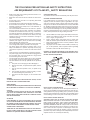
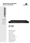
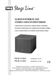
GFA-555se
OWNER’S MANUAL
High-Current Power Amplifier
Congratulations on your purchase of the Adcom GFA-555se
You have made a wise choice that will reward you with exceptionally accurate musical sound reproduction for
years to come. To realize the full potential of your new amplifier, please read these operating and installation
instructions thoroughly before attempting to make any connections to it.
The GFA-555se is not only designed to reproduce the highest quality sound but also to deliver the greatest
possible value. It is our engineers’ passion for perfection that has enabled our components to be judged the
equivalent of others costing two, three, or even five times as much. Our engineering team consistently strives
to develop and design products that will exceed your expectations. Our goal at Adcom is to let more consumers hear high-end quality sound without paying high-end prices.
All Adcom components are the result of a long-standing dedication to innovation, quality, simplicity, and value.
Adcom: We have the power — and now, so do you!
AVERTISSEMENT
DANGER D’ÉLECTROCUTION
NE PAS OUVRIR
WARNING: TO REDUCE THE RISK OF ELECTRIC SHOCK,
DO NOT REMOVE COVER (OR BACK);
NO USER-SERVICEABLE PARTS INSIDE;,
REFER SERVICING TO QUALIFIED SERVICE PERSONNEL.
AVERTISSEMENT:POUR ÉLIMINER TOUT RISQUE
D’ÉLECTROCUTION, NE PAS OUVRIR LE COUVERCLE (OU
LA PARTIE ARRIÈRE). AUCUNE PIECE RÉPARABLE PAR
L’UTILISATEUR NE SE TROUVE À L’INTÉRIEUR. POUR
TOUTE INTERVENTION D’ENTRETIEN OU DE RÉPARATION
SE CONFIER AUX TECHNICIENS QUALIFIÉS.
The lightning flash with arrowhead symbol, within an equilateral triangle, is intended to alert the user to the presence
of uninsulated “dangerous voltage” within
the product’s enclosure that may be of
sufficient magnitude to constitute a risk
of electric shock.
La flèche symbolisant l’éclair dans un
triangle équilateral a pour objet de tirer
l’attention de l’utilisateur sur le fait, qu’
il y a des “tensions dangereuses” nonisolées à l’intérieurde l’enceinte du
produit qui peuvent être suffisamment
importantes pour conduire au risque
d’électrocution.
The exclamation point within an equilateral triangle is intended to alert the user
to the presence of important operating
and maintenance (servicing) instructions
in the literature accompanying the appliance.
Le point d’exclamation au sein d’un triangle équilateral a pour objet de tirer
l’attention de l’utilisateur sur le fait qu’
il y a des instructions de mise en service et d’entretien (de réparation) dans
les fiches descriptives de l’appareil qui
doivent obligatoirement être respectées.
Do not place this unit on an unstable
cart, stand, tripod, bracket, or table. The
unit may fall, causing serious injury to a
child or adult, and serious damage to the
unit. Use only with a cart, stand, tripod,
bracket, or table recommended by the
manufacturer or sold with the unit. Any
mounting of the device should follow the
manufacturer’s instructions, and should
use a mounting accessory recommended
by the manufacturer.
2
TABLE OF CONTENTS
LETTER FROM THE ADCOM TEAM. . . . . . . . . . . . . . . . . 2
SAFETY INFORMATION . . . . . . . . . . . . . . . . . . . . . . . . . . . . 4
DESCRIPTION OF UNIT
GFA-555se FEATURES . . . . . . . . . . . . . . . . . . . . . . . . . . . . . 5
WARRANTY INFORMATION . . . . . . . . . . . . . . . . . . . . . . . . . 5
INSTALLATION & HOOKUP
UNPACKING THE GFA-555se . . . . . . . . . . . . . . . . . . . . . . . . 6
INSTALLING THE GFA-555se . . . . . . . . . . . . . . . . . . . . . . . . 6
CONNECTING THE GFA-555se . . . . . . . . . . . . . . . . . . . . . . 7
STEREO/BRIDGED MONO INPUT/OUTPUT.............7-8
OPERATION
FRONT AND REAR PANEL DIAGRAMS . . . . . . . . . . . . . . . . 9
DESCRIPTION OF UNIT: REAR PANEL .... . . . . . . . . 10-11
DESCRIPTION OF UNIT: FRONT PANEL . . . . . . . . . . . . . 11
TROUBLESHOOTING
RESOLVING PROBLEMS . . . . . . . . . . . . . . . . . . . . . . . . . . . 12
CARING FOR YOUR GFA-555se . . . . . . . . . . . . . . . . . . . 13
SERVICE INFORMATION . . . . . . . . . . . . . . . . . . . . . . . . . . 13
GFA-555se SPECIFICATIONS . . . . . . . . . . . . . . . . . . . 14-15
THE FOLLOWING PRECAUTIONS AND SAFETY INSTRUCTIONS
ARE REQUIREMENTS OF ETL AND ETLC SAFETY REGULATIONS
•
•
•
•
•
•
•
•
•
•
•
•
•
Read all the safety and operating instructions before connecting or using this unit.
Retain this notice and the owner’s manual for future reference.
All warnings on the unit and in its operating instructions
should be adhered to.
All operating and use instructions should be followed.
Do not use this unit near water. For example, near a bathtub,
washbowl, kitchen sink, laundry tub, in a wet basement, or
near a swimming pool.
The unit should be installed so that its location or position
does not interfere with its proper ventilation. For example,
it should not be situated on a bed, sofa, rug, or similar surface that may block the ventilation openings; or placed in a
built-in installation, such as bookcase or cabinet, that may
impede the flow of air around its heatsinks or through its
ventilation openings.
The unit should be situated away from heat sources such as
radiators, heat registers, stoves, or other devices (including
other amplifiers) that produce heat.
The unit should be connected to a power supply outlet only
of the voltage and frequency marked on its rear panel.
The power supply cord should be routed so that it is not
likely to be walked on or pinched, especially near the plug,
convenience receptacles, or where the cord exits from the
unit.
Clean unit only as recommended in its instruction manual.
The power supply cord of the unit should be unplugged from
the wall outlet when it is to be unused for a long period of
time and during electrical storms.
Care should be taken so that objects do not fall, and liquids
are not spilled, into the enclosure through any openings.
This unit should be serviced by qualified service personnel
when:
a. The power cord or the plug has been damaged; or
b. Objects have fallen, or liquid has been spilled, into the
unit; or
c. The unit has been exposed to rain, or liquids of any
kind; or
d. The unit does not appear to operate normally, or exhibits a marked change in performance; or
e. The device has been dropped, or the enclosure damaged.
CAUTION POWER LINES
Any outdoor antenna must be located away from all power lines.
OUTDOOR ANTENNA GROUNDING
If an outside antenna is connected to your tuner or tuner/preamplifier, be sure the antenna system is grounded so as to provide some protection against voltage surges and built-up static
charges. Section 810 of the National Electrical Code, ANSI/NFPA
No. 701984, provides information with respect to proper grounding of the mast and supporting structure, grounding of the lead-in
wire to an antenna discharge unit, size of grounding conductors,
location of antenna discharge unit, connection to grounding electrodes, and requirements for the grounding electrode.
a.
b.
c.
d.
Use No.10 AWG (5.3 mm2) copper, No.8 AWG (8.4 mm2) aluminum, No.17 AWG (1.0 mm2) copper clad steel or bronze
wire, or larger, as a ground wire.
Secure antenna lead-in and ground wires to house with
stand-off insulators spaced from 46 feet (1.221.83 m) apart.
Mount antenna discharge unit as close as possible to where
lead-in enters house.
Use jumper wire not smaller than No.6 AWG (13.3 mm2) copper, or the equivalent, when a separate antenna grounding
electrode is used. See NEC Section 810-21 (j).
EXAMPLE OF ANTENNA GROUNDING AS PER NATIONAL ELECTRICAL CODE INSTRUCTIONS CONTAINED IN ARTICLE 810. RADIO AND TELEVISION EQUIPMENT.
WARNING
TO REDUCE THE RISK OF FIRE OR ELECTRIC SHOCK, DO NOT
EXPOSE THIS UNIT TO RAIN OR MOISTURE.
AVERTISSEMENT
AFIN D’ÉVITER TOUT RISQUE D’INCENDIE OU D’ÉLECTROCUTION,
NE PAS EXPOSER CET APPAREIL À LA PLUIE NI À L’HUMIDITÉ.
NOTE TO CATV SYSTEM INSTALLER
This reminder is provided to call the CATV system installer’s attention to Article 82022 of the National Electrical Code that provides guidelines for proper grounding and, in particular, specifies
that the cable ground shall be connected to the grounding system
of the building, as close to the point of cable entry as practical.
CAUTION
TO PREVENT ELECTRIC SHOCK DO NOT USE THIS POLARIZED
PLUG WITH AN EXTENSION CORD, RECEPTACLE OR OTHER
OUTLET UNLESS THE BLADES CAN BE FULLY INSERTED TO PREVENT BLADE EXPOSURE.
NOTE TO AUDIO SYSTEM INSTALLER
WHENEVER CONNECTIONS TO OR FROM THE GFA-555SE ARE BEING
MADE, BE CERTAIN THAT THE AC ON/OFF SWITCH OF THE AMPLIFIER IS IN THE OFF POSITION, THE AC CORD OF THE AMPLIFIER IS
DISCONNECTED FROM THE AC WALL OUTLET AND THAT ALL ASSOCIATED COMPONENTS ARE OFF. Always make certain that the
amplifier is disconnected from the AC outlet for at least five minutes to ensure its filter capacitors are discharged before making connections to and from the amplifier. Failure to heed this
precaution may result in damage to the loudspeaker(s) and/or the
amplifier which is not covered by the Warranty.
ATTENTION
POUR PRÉVENIR LES CHOCS ÉLECTRIQUES NE PAS UTILISER
CETTE FICHE POLARISÉE AVEC UN PROLONGATEUR, UNE PRISE
DE COURANT OU UNE AUTRE SORTIE DE COURANT, SAUF SI LES
LAMES PEUVENT ÊTRE INSÉRÉES À FOND SANS EN LAISSER
AUCUNE PARTIE À DÉCOUVERT.
THERE ARE NO USER SERVICEABLE PARTS IN THIS PRODUCT.
DO NOT ATTEMPT SERVICING OF THIS UNIT YOURSELF. REFER
SERVICING TO QUALIFIED SERVICE PERSONNEL.
4
GFA-555se FEATURES
• Precision-matched devices used throughout the signal path.
• 60,000 μF of power supply-filter capacitance for greater reserve capacity.
• Independent power supplies for each channel.
• Fewer gain stages improve signal reproduction accuracy.
• Custom toroidal power transformer provides better regulation and greater peak current
capability.
• Independent distortion LED for each channel.
• High quality, gold-plated 5-way binding posts.
• High quality, gold-plated RCA jacks.
• High quality, balanced XLR jacks.
• Large independent heatsinks for greater cooling capability of output devices.
• Heavy gauge, anodized aluminum front panel.
• Powder-coated, baked chassis and top cover for greater durability.
• Cooling vents for greater efficiency and cooler operation while driving low impedance
loads.
ADCOM Protection Plan (USA Only)
ADCOM offers the enclosed valuable Limited Warranty. Please read the details on the Warranty Card carefully to
understand the extent of the protection offered by the Warranty, its reasonable limitations, and what you should
do in order to obtain its benefits. Be sure to verify that the serial number printed on the rear panel matches the
serial number on the outer carton. If any number is altered or missing, or if the ADCOM Warranty Card is not
included in the carton, you should notify us immediately in order to ensure that you have received a genuine
ADCOM product which has not been opened, mishandled, or tampered with in any way. Always retain your
original sales receipt as a proof of purchase. A proof of purchase is required for all warranty service.
5
INTRODUCTION
Congratulations on your decision to purchase the GFA-555se power amplifier. By use of updated components in the classic
ADCOM GFA-555 design, we have reestablished our heritage of high performance and audiophile quality at the greatest
possible value. You have made a wise choice that will reward you for years to come with exceptionally accurate and
musical sound reproduction. To realize the full potential of your new amplifier, and before making any connections to it,
please read these operating and installation instructions thoroughly.
UNPACKING THE GFA-555se
Before your new ADCOM amplifier left our factory, it was carefully inspected for physical imperfections and tested for
all electrical parameters as a routine part of ADCOM’s systematic quality control. This, along with full operational and
mechanical testing, should ensure a product flawless in both appearance and performance. After you have unpacked the
GFA-555se, inspect it for physical damage. Save the shipping carton and all packing material as they are intended to
reduce the possibility of transportation damage, should the amplifier ever need to be shipped again. In the unlikely event
damage has occurred, notify your dealer immediately and request the name of the carrier so a written claim to cover
shipping damages can be initiated. THE RIGHT TO A CLAIM AGAINST A PUBLIC CARRIER CAN BE FORFEITED IF THE CARRIER
IS NOT NOTIFIED PROMPTLY IN WRITING AND IF THE SHIPPING CARTON AND PACKING MATERIALS ARE NOT AVAILABLE FOR
INSPECTION BY THE CARRIER. SAVE ALL PACKING MATERIALS UNTIL THE CLAIM HAS BEEN SETTLED.
INSTALLING THE GFA-555se
During normal home operation the internal heatsinks of the GFA-555se may become warm. However, there are instances
during high-level playback into low impedances when the heatsinks will become much warmer than usual. To ensure the
amplifier’s long-term, trouble-free operation it is necessary to provide adequate ventilation for the heatsinks. Therefore,
the GFA-555se should be kept away from external sources of heat such as radiators and hot-air ducts. The GFA-555se
should never be placed with other heat-producing components in a cabinet or enclosure lacking free air flow. The top
and bottom panel of the amplifier’s chassis have been provided with vents to allow the necessary cooling of the internal
components. It is imperative that these vents are not obstructed in any way.
We recommend that you do not stack other components on top of the GFA-555se. This is particularly important if your
system includes low-impedance loudspeakers which are difficult to drive, or if you will consistently demand high volume
levels from the amplifier and speaker system. Not only will heat generated by the amplifier affect the performance of
equipment stacked on top of the GFA-555se, but the free flow of air through the ventilating slots in the amplifier may be
partially obstructed.
If you observe these recommendations, the GFA-555se will perform reliably in any reasonable environment. You should
also pay attention to such normal considerations as protection from excessive dust and moisture. Occasional vacuuming
of accumulated dust on the chassis, panels and around the ventilating slots should be all that is required. The optimal
performance of your new GFA-555se will ultimately depend on the care with which you make the connections between
the amplifier, preamplifier and the loudspeakers. All input and output signal connections should be made only with high
quality, low-loss, low capacitance cables following the recommendations in the Inputs and Outputs section of CONNECTING
THE GFA-555se.
6
CONNECTING THE GFA-555se
When connecting the amplifier to the loudspeaker, it is vital to maintain proper polarity (positive to positive, negative to
negative). On the GFA-555se , the positive terminal is color coded RED and labeled “+”, and the negative is color coded
BLACK and labeled “-”. The positive terminal on the speaker will be color coded RED, or will be labeled “+”, “pos”,
“positive”, “8 ohms” or “4 ohms”. The negative terminal on the speaker will be color coded BLACK, or will be labeled
“-”, “neg”, “negative”, “C”, “Common”, “G”, or “ground”.
It is recommended that your speaker cables be terminated with “U” type spade connectors. These will give the most
contact area insuring long-term reliability. The spade connector should have a maximum width of 0.57 inches and an
opening width of no less than 0.25”.
To properly connect the speaker cable to the binding posts, turn the insulated head of the binding post clockwise until the
wire or connector is firmly secured. Finger pressure is sufficient and you should not use pliers or other tools which could
damage or over-tighten the binding-post assembly. The binding posts have been designed in such a way that finger pressure
is all that is required to cause a “pinching” action among the different metal surfaces to ensure proper connection.
It is very important to use the correct size of wire in order to avoid unnecessary loss of amplifier power in the cable,
reduction of amplifier damping factor and other undesirable conditions. Sound audio engineering practice suggests the
use of at least AWG16, stranded, copper cable. Recommended capacitance of the speaker wire should not exceed 5OpF
per foot. This insures high frequencies will not be rolled-off.
All loudspeakers having a nominal impedance down to 4 ohms can be connected to and driven by the GFA-555se. The
amplifier can drive these low-impedance speakers at more than adequate power levels with no difficulty. It should be
noted that many loudspeaker systems which are nominally rated at 4 ohms drop in impedance, in some parts of their
frequency range, to as low as 2 ohms (and sometimes less). You will not experience difficulties even with these very low
impedance loads unless you demand excessively high volumes levels from your system.
It is suggested to follow this chart for speaker lengths and wire gauges. If longer runs are needed, it is best to consult
with your ADCOM Dealer to maximize the performance of your system with your exact conditions.
up to 24 feet
AWGI6
up to 36 feet
AWGI4
up to 58 feet
AWGI2
STEREO/BRIDGED MONO INPUT/OUTPUT
The GFA-555se can be used as a very powerful mono amplifier to drive 8-ohm impedance loudspeakers when in its
“bridged” mode. No modification to the amplifier is necessary for operation in the bridged mode, nor are any additional
accessories required. However, you will need two GFA-555ses for stereophonic reproduction, if you are using them in
the bridged mono mode.
7
To set the amplifier in bridged mono operation, flip the STEREO/BRIDGED input switch into the BRIDGED position. When
in the bridged mono mode, input to the amplifier is made only through the LEFT input jack. The connection to the RIGHT
input jack should be removed since the right-channel input portion of the amplifier is inoperative.
Only a single loudspeaker is to be connected to the GFA-555se when in the bridged mono mode. Please note that
connections made to the loudspeaker from the GFA-555se, when used in the bridged mono mode, are different from
those made when the amplifier is used in the stereo mode. The LEFT RED output binding-post terminal (labeled
BRIDGED MONO OUTPUT “+”) should be connected to the loudspeaker input terminal color-coded RED (or labeled
POSITIVE, “+”, POS, 8 OHMS or 4 OHMS). The RIGHT RED output binding post terminal on the amplifier (labeled BRIDGED
MONO OUTPUT “-”) should be connected to the BLACK loudspeaker terminal (or labeled NEG, “-”, C, COM, COMMON,
G, or GROUND). Please note that if you want to insure correct stereo phasing with optimal bass response, you must
observe these connections precisely.
Although the GFA-555se can generate a substantially greater amount of power in the bridged mono mode than when it
is in its normal stereo mode, it requires the use of loudspeakers whose nominal impedance does not drop below 4 ohms.
It is not recommended that the GFA-555se be used in the bridged mono mode into loudspeakers, or multiple loudspeaker
loads, which drop in value substantially below 4 ohms. Otherwise, you may trigger the THERMAL PROTECTION or blow
one of the DC RAIL FUSES. A little known fact is that when any amplifier is operated in the bridged mode, the load is
“split” between the two amplifiers in the bridged configuration. Therefore, an 8-ohm loudspeaker will be seen by the
amplifier as if it were a 4-ohm load; a 4-ohm loudspeaker load will be seen by the amplifier as a 2-ohm load.
NOTES:
a) If the connections described above are followed exactly, the GFA-555se will be polarity correct, that is, it will not
invert “phase”. Any positive-going signal at its input will appear as a positive-going signal at the loudspeaker.
b) For use in professional installations, the GFA-555se may be mounted in a standard 19-inch rack using the optional
RM-7 rack-mount adaptors available through ADCOM dealers. If the GFA-555se is to be mounted on a rack, along with
other components which are interconnected to the GFA-555se, the amplifier’s chassis must be insulated from the
metal-rack rails to prevent ground loops, especially if the rack is grounded to “earth”, and to avoid defeating the audio
grounding scheme of the power amplifier (the audio-input grounds are isolated from and above the chassis ground).
Please consult the instruction sheet packed with the optional rack-mount adaptors for more information.
c) The DC RAIL FUSES provide protection for the output stages and power supply in the event of excessive current
demands from the amplifier, either long-term or short-term. If the amplifier ceases to operate, either on one or both
channels, particularly during high-level passages, or long-term high-volume playback, and the POWER LED glows while
the THERMAL PROTECTION LED is out, the chances are that one or both of the DC RAIL FUSES on that channel, or both
channels, are blown. In the event that the DC RAIL FUSES need to be replaced, refer servicing to qualified service
personel. DO NOT USE ANY SUBSTITUTE FUSES WITH DIFFERENT RATINGS, TIME-CURRENT CURVES OR VALUES. Failure to
observe this precaution may cause serious damage to the amplifier circuits, MAY CREATE A FIRE HAZARD, AND MAY VOID
YOUR WARRANTY.
8
REAR PANEL
(1 )
(1 )
(2 )
(2 )
(6 )
(3 )
(4 )
(5 )
FRONT PANEL
model GFA-555se
power
(7 )
high current power amplifier
instantaneous distortion alert
R
L
channel
(8 )
(10)
thermal protection
(9 )
(1) Inputs (unbalanced)
(6) Mode Switches
(2) Inputs (balanced)
(7) On/Off Switch
(3) Output Binding Posts
(8) Power LED
(4) AC Fuse
(9) Thermal Protection LED
(5) AC Power Cord
(10) Distortion Alert LEDs
9
DESCRIPTION OF UNIT: REAR PANEL
low-impedance loudspeakers. In either case, BE SURE TO
REPLACE THE AC Fuse ONLY WITH AN EXACT REPLACEMENT
FUSE. The proper fuse values are:
(1) Inputs (unbalanced)
The audio inputs for the GFA-555se are through
high-quality, gold-plated RCA jacks to minimize
high-frequency losses, noise, etc. They will accept
standard RCA-type plugs, one for each channel; Left and
Right. To insure that the performance designed into the
amp is preserved, you should use the highest quality
audio cables possible. There are many cables which are
color-coded and specifically designed for this application.
Your ADCOM dealer can help select the best cable for
your needs. (See CONNECTING THE GFA-555se for more
information).
GFA-555se for 115 volt operation
Fuse Rating
BUSS®
Littelfuse®
12 Amp 250 Volt ... AGC-12/250V .... (3AB) 314012/250V
GFA-555se for 230 volt operation
Fuse Rating
BUSS®
Littelfuse®
6 Amp 250 Volt .... AGC-6/250V ..... (3AG) 314006/250V
Before attempting to replace a failed fuse, be certain
to unplug the AC Power Cord from the AC wall outlet to
prevent possible electrical shock. Replace the AC Fuse
only with one identical in type and rating as printed on
the rear panel. DO NOT USE ANY SUBSTITUTE FUSES WITH
DIFFERENT RATINGS OR VALUES. Failure to observe this
precaution may cause serious damage to the amplifier
circuits, may create a hazard fire, and may void the warranty.
If the Power LED (8) does not glow, it may be an indication
that the AC fuse has blown. If you are not sure, or the
amplifier displays other symptoms, please consult the
RESOLVING PROBLEMS section on page 12.
(2) Inputs (balanced)
The audio inputs for the GFA-555se are through
high-quality, Balanced XLR jacks to minimize
high-frequency losses, noise, etc. They will accept
standard XLR-type plugs, one for each channel; Left and
Right. To insure that the performance designed into the
amp is preserved, you should use the highest quality
audio cables possible. There are many cables specifically
designed for this application. Your ADCOM dealer can help
select the best cable for your needs. (See CONNECTING
THE GFA-555se for more information).
Fuse replacement
To remove the fuse-holder cap, you will need a #2 standard
Phillips screwdriver. Place the screwdriver in the recessed
“crosshead” in the cap. Turn the cap counter-clockwise,
until the cap releases out towards you. Grasp the cap with
your fingers and pull it completely out. The fuse is inserted
in the back of the cap; gently pull it free.
(3) Outputs
The GFA-555se connections to the loudspeakers are made
through high-grade, 5-way, gold-plated binding post
terminals. There are two terminals for each speaker,
which are colored RED for the positive (+) output and
BLACK for the negative (-) output.
The binding posts will accept a variety of connector types;
the most secure and prevalent of these is the “U”-type
spade connectors (at least 0.25’’ wide and maximum
width of 0.57”),. The terminal will also accept bare wire
(up to AWG1O) and “banana” type plugs (single or dual).
(Refer to your User Manual for your speakers for additional
information).
Since the fuse has a ceramic body, you cannot visually
examine the fuse element, it is therefore suggested that
you replace it with an identical substitute or bring the fuse
to your ADCOM dealer so they may check its integrity. To
replace the fuse, insert it in the back of the fuse-holder
cap. Place the cap into the fuse-holder. Place the
screwdriver in the recessed slot, gently press in and turn
1/8-turn clockwise.
(5) AC Power Cord
(4) AC Fuse
The AC Fuse protects the electronic circuits of the GFA555se. This fuse, normally, will fail only if there is an
overload within the GFA-555se. It may, however, fail if the
amplifier attempts to deliver very high power into very
10
The AC cord provides power to operate all the GFA-555se’s
circuits. Its plug can be connected to a standard wall
outlet provided the outlet supplies a voltage compatible
with the power requirements printed on the rear panel of
the GFA-555se.
(6) Mode Switches
For normal stereophonic mode of operation, the
STEREO/BRIDGED input switch should be set to STEREO.
Otherwise, the amplifier will operate in the bridged
mono input mode by which you will amplify only the
left channel through both outputs of the amplifier. The
BALANCED/UNBALANCED selector switches should be set
to accommodate the type of input connectors that you
are using. The upper connectors (RCA-jacks) are used for
unbalanced input signals and the lower connectors (XLRjacks) are used for balanced input signals.
DESCRIPTION OF UNIT: FRONT PANEL
(7) On/Off Switch
The On/Off Switch controls AC power to the power
transformer and circuits of the GFA-555se. Whenever the
GFA-555se is energized the Power LED (8) will glow red. To
turn the GFA-555se on, press the button up. It will remain
in the “engaged” position while the unit is energized. To
turn the GFA-555se off, press the button down and it will
move to the “disengaged” position.
(8) Power LED
This LED will glow whenever the On/Off Switch (7) is
turned on and the GFA-555se is energized. The Power
LED indicates that there is AC voltage being fed to the
amplifier, but it does not signify that all the amplifier’s
circuits are in operation. If, for example, the Thermal
Protection LED (9) glows, that amplifier will not produce
sound even though the Power LED may still glow. When
the GFA-555se is turned off, the Power LED will take some
time to fade out completely. It may take up to 30 seconds
to fully extinguish.
Additionally, the internal power transformer is provided
with a thermostat which will interrupt power into the
transformer if its temperature exceeds 125°C. This high
temperature will seldom, if ever, be encountered unless
the amplifier is subjected to abnormal conditions, such
as operation into loads of less than 3 ohms at very high
listening levels, etc. If the AC Fuse (4) has not failed, the
Power LED (8) is out, and the Thermal Protection LED (9)
does not glow, this would indicate that the thermostat
within the transformer has opened.
automatically and normal operation will resume. If you
are to avoid tripping the thermostat in the transformer
continually, you must reduce the sound level demands,
correct the load impedance of the loudspeakers, or both.
(9) Thermal Protection LED
The GFA-555se is provided with a thermal protection
circuit which will shut down the amplifier if its heatsink
temperature reaches 75°C. The Thermal Protection LED
will light whenever the thermal protection circuit has been
triggered and the amplifier is inoperative. The thermal
protection circuitry will typically be triggered by very
high power demands into impedances much lower than
the amplifier is capable of driving at those levels. If any
amplifier channel’s output through the loudspeaker(s)
ceases abruptly, and its Thermal Protection LED glows,
you will know that its heatsink temperature has become
unacceptably high and the circuitry is protecting the
amplification devices. Please note that the Power LED (8)
will remain on and the amplifier will still be energized.
Once the temperature of the heatsink(s) drops to a safe
operating level, that amplifier will automatically resume
operation.
(10) Distortion Alert LEDs
The Distortion Alert circuit is a unique ADCOM distortion
detection system which reads all forms of non-linear
distortion such as THD, IM, slew-induced, “clipping”, etc.
The Distortion Alert LEDs will light when distortion reaches
approximately 1% regardless of impedance, voltage/
current phase angle or the reactance of the loudspeakers
which the amplifier is driving. Sometimes, when the
amplifier is in use, the LEDs may occasionally flicker
during high volume listening, particularly if you are driving
low impedances. This flickering is no cause for concern.
The LEDs are simply warning you that the amplifier is
approaching its maximum power output into the particular
loudspeakers you are using. If, however, the Distortion
Alert LEDs glow brightly or are illuminated most of the
time during playback, you are over driving the amplifier
and should turn down your volume control to reduce
the listening level, otherwise it may cause the Thermal
Protection to be activated or, in extreme cases, damage
your loudspeakers.
Once the temperature within the transformer decreases
to a normal level, the thermostat will reset itself
11
RESOLVING PROBLEMS
Use the chart below to solve common situations that don’t require professional attention. If the steps stated in
POSSIBLE SOLUTION do not resolve your problem, then please contact your ADCOM Dealer or call the ADCOM Customer
Service Department. Any problems not covered here should be brought to the attention of your ADCOM Dealer or ADCOM
Customer Service Department.
SYMPTOM
POSSIBLE REASON
POSSIBLE SOLUTION
Power LED does not
glow.
AC Power Cord(s) not plugged in.
Power switch not (pressed) on.
Plug in AC Power Cord(s).
Press the Power switch.
No sound.
AC Fuse(s) failed.
Transformer thermal protection engaged.
Preamp or source unit is not on.
Connections in rear of amp are loose.
INPUT(s) or OUTPUT(s) connector
disconnected or loose.
Speaker disconnected.
Internal protection engaged.
Replace AC Fuse(s).
Wait until unit cools down. It will reset.
Make sure whole system is on.
Verify all connections on rear of amp.
Verify both connections on that channel.
Ground loop (difference in ground voltages
between components).
Problem with source unit (CD, tape, etc.),
or RCA cable connecting that source unit
to the preamp.
Some major appliance, dimmer, halogen or
fluorescent light is creating interference.
If Cable TV is present (see Note 1).
If Cable TV is not present (see Note 2).
Try different source (tuner, tape, etc.)
and/or different RCA cable.
Power LED glows,
but no sound.
One channel not
producing sound.
Hum from all speakers
at any volume.
Hum from all speakers
(hum goes up or
down with volume).
Hum from the amplifier
itself.
Verify connection at speaker.
Bring to Dealer or Service Center.
Make sure all appliances, dimmers and
suspect lights are off.
A special note on “hum” When there is a low-volume “hum” audible throughout your speakers, even with the main
volume turned all the way down, you have a common phenomenon known as a “ground loop”. A ground loop is basically
a difference in ground voltages between two or more components which are connected electrically and which creates
multiple current paths where there must only be one. This difference in potentials creates a 60Hz low-level sound
(approximately a low A#), that seems to “hum”, hence the name.
It can be caused by adding new components to your system, but that does not imply there is anything electrically
wrong with any new component. With the advent of audio/video and home theater systems, the problem has
become commonplace. Generally, the cause is the Cable-TV incoming signal line. This new incoming line may add an
additional ground at a different potential to the AC line ground of your other equipment (refer to Note I and 2 below to
troubleshoot a hum problem).
Note 1 Cable TV systems can sometimes contribute to ground loop problems which cause “hum”. To determine if your
cable system is the contributing factor, disconnect the Cable-TV incoming signal line (round coax, 75Ω) at the wall, or
the first component the cable is connected to (i.e. the cable box, or VCR). If the hum is no longer present, you must
insert a “75Ω Ground Loop Isolator” before reconnecting the line. You should check with your ADCOM Dealer to obtain
one. If the “75Ω Ground Loop Isolator” works only partially or not at all, then please read Note 2 to complete the
troubleshooting procedure.
Note 2 Make sure that the power amplifier is at least 6” from the Preamp and/or Processor. Usually putting another
component between them is sufficient to minimize the hum. If this does not reduce the hum, turn the system off and
disconnect all Inputs from the amplifier. Turn the amplifier on, if the hum still persists, then your Dealer or Service
Center must examine the amplifier. If the hum disappears, try a different set of RCA cables. Connect one RCA cable
at a time to see if one specific cable is responsible. If any or all cables cause the hum to appear, then the preamp or
processor should be evaluated for proper operation by your Dealer or Authorized Service Center.
12
CARING FOR YOUR GFA-555se
Great care has been taken by ADCOM to ensure that your amplifier is as flawless in appearance as it is electronically.
The front panel is a heavy-gauge, high-grade aluminum extrusion carefully finished and anodized for durability. The
chassis, top cover and rear panel are heavy-gauge steel that has been powder coated and baked to ensure a lasting
finish. If the front panel, top or sides become dusty or fingerprinted, they can be cleaned with a soft lint-free cloth,
slightly dampened with a very mild detergent solution or glass cleaner.
Do not spray or pour liquids of any kind directly onto the GFA-555se.
SERVICING
ADCOM has a Technical Service Department to answer questions pertinent to the installation and operation of your
unit. In the event of difficulty, please contact us for prompt advice. If your problem cannot be resolved through our
combined efforts, we may refer you to an authorized repair agency, or authorize return of the unit to our warehouse.
To aid us in directing you to a convenient service center, it would be helpful if you indicate which major city is accessible
to your home.
Please address mail inquires to:
Phone, Fax or e-mail inquires to:
ADCOM Service
8541 East Anderson Drive, Suite 101
Scottsdale, Arizona 85255 USA
Voice: (480) 607-2277
Fax: (480) 348-9876
Monday through Friday
9:00 AM to 5:00 PM MST
E-mail: [email protected]
For Fax inquires, please include a return Fax number for the reply.
When calling or writing about your GFA-555se, be sure to note and refer to its serial number as well as the date of
purchase and the dealer from whom it was purchased. In any communications to us, please include a daytime phone
number where we may reach you. In the event the unit must be returned to our factory for service, you will be instructed
on the proper procedure when you call or write for a Return Authorization. UNDER NO CIRCUMSTANCES SHOULD YOUR
UNIT BE SHIPPED TO OUR FACTORY WITHOUT PRIOR AUTHORIZATION, OR PACKED IN OTHER THAN ITS ORIGINAL CARTON
AND FILLERS.
If the original shipping carton and its fillers have been lost, discarded, or damaged, a duplicate carton may be obtained
from our Service Department for a nominal charge.
Always ship PREPAID VIA UNITED PARCEL SERVICE (UPS) OR OTHER APPROVED CARRIER. DO NOT SHIP VIA PARCEL POST,
since the packing was not designed to withstand rough Parcel Post handling.
FREIGHT COLLECT SHIPMENTS WILL NOT BE ACCEPTED
UNDER ANY CIRCUMSTANCES.
13
GFA-555se SPECIFICATIONS
Power Rating (To FTC Requirements)
200 Watts continuous average power into 8 ohms at any frequency between 20Hz and 20kHz with both channels
driven at less than 0..04% THD.
300 Watts continuous average power into 4 ohms at any frequency between 20Hz and 20khz with both channels
driven at less than 0.04% THD. *
600 Watts continuous average power into 8 ohms at any frequency between 20Hz and 20kHz at less than 0..09% THD,
bridged. *
IM Distortion (SMPTE)
1 watt to 200 watts into 8 ohms. . . . . . . . . . . . . . . . . . . . . . . . . . . . . . . . . . . . . . . . . . . . . . . . . . . . . . . . . ≤ 0.009%
1 watt to 300 watts into 4 ohms. . . . . . . . . . . . . . . . . . . . . . . . . . . . . . . . . . . . . . . . . . . . . . . . . . . . . . . . . ≤ 0.009%
IM Distortion (CCIF, Any Combination from 4kHz to 20kHz)
200 watts into 8 ohms. . . . . . . . . . . . . . . . . . . . . . . . . . . . . . . . . . . . . . . . . . . . . . . . . . . . . . . . . . . . . . . . . ≤ 0.002%
300 watts into 4 ohms. . . . . . . . . . . . . . . . . . . . . . . . . . . . . . . . . . . . . . . . . . . . . . . . . . . . . . . . . . . . . . . . . ≤ 0.003%
THD + Noise at 200 watts into 8 Ohms (Typical)
20Hz. . . . . . . . . . . . . . . . . . . . . . . . . . . . . . . . . . . . . . . . . . . . . . . . . . . . . . . . . . . . . . . . . . . . . . . . . . . . . . . .
1kHz. . . . . . . . . . . . . . . . . . . . . . . . . . . . . . . . . . . . . . . . . . . . . . . . . . . . . . . . . . . . . . . . . . . . . . . . . . . . . . . .
10kHz. . . . . . . . . . . . . . . . . . . . . . . . . . . . . . . . . . . . . . . . . . . . . . . . . . . . . . . . . . . . . . . . . . . . . . . . . . . . . . .
20kHz. . . . . . . . . . . . . . . . . . . . . . . . . . . . . . . . . . . . . . . . . . . . . . . . . . . . . . . . . . . . . . . . . . . . . . . . . . . . . . .
0.004%
0.003%
0.006%
0.010%
THD + Noise at 300 watts into 4 Ohms (Typical)
20Hz. . . . . . . . . . . . . . . . . . . . . . . . . . . . . . . . . . . . . . . . . . . . . . . . . . . . . . . . . . . . . . . . . . . . . . . . . . . . . . . .
1 kHz. . . . . . . . . . . . . . . . . . . . . . . . . . . . . . . . . . . . . . . . . . . . . . . . . . . . . . . . . . . . . . . . . . . . . . . . . . . . . . .
10kHz. . . . . . . . . . . . . . . . . . . . . . . . . . . . . . . . . . . . . . . . . . . . . . . . . . . . . . . . . . . . . . . . . . . . . . . . . . . . . . .
20kHz. . . . . . . . . . . . . . . . . . . . . . . . . . . . . . . . . . . . . . . . . . . . . . . . . . . . . . . . . . . . . . . . . . . . . . . . . . . . . . .
0.005%
0.004%
0.015%
0.025%
IM Distortion, Bridged (SMPTE)
1 watt to 600 watts into 8 ohms. . . . . . . . . . . . . . . . . . . . . . . . . . . . . . . . . . . . . . . . . . . . . . . . . . . . . . . . . . ≤ 0.05%
1 watt to 850 watts into 4 ohms. . . . . . . . . . . . . . . . . . . . . . . . . . . . . . . . . . . . . . . . . . . . . . . . . . . . . . . . . . ≤ 0.05%
IM Distortion (CCIF, Any Combination from 4kHz to 20kHz)
600 watts into 8 ohms. . . . . . . . . . . . . . . . . . . . . . . . . . . . . . . . . . . . . . . . . . . . . . . . . . . . . . . . . . . . . . . . . ≤ 0.005%
850 watts into 4 ohms. . . . . . . . . . . . . . . . . . . . . . . . . . . . . . . . . . . . . . . . . . . . . . . . . . . . . . . . . . . . . . . . . ≤ 0.005%
THD + Noise at 600 watts into 8 Ohms, Bridged (Typical)
20Hz. . . . . . . . . . . . . . . . . . . . . . . . . . . . . . . . . . . . . . . . . . . . . . . . . . . . . . . . . . . . . . . . . . . . . . . . . . . . . . . . 0.004%
1kHz. . . . . . . . . . . . . . . . . . . . . . . . . . . . . . . . . . . . . . . . . . . . . . . . . . . . . . . . . . . . . . . . . . . . . . . . . . . . . . . . 0.004%
10kHz. . . . . . . . . . . . . . . . . . . . . . . . . . . . . . . . . . . . . . . . . . . . . . . . . . . . . . . . . . . . . . . . . . . . . . . . . . . . . . . . 0.02%
20kHz. . . . . . . . . . . . . . . . . . . . . . . . . . . . . . . . . . . . . . . . . . . . . . . . . . . . . . . . . . . . . . . . . . . . . . . . . . . . . . . . 0.04%
Frequency Response @ I Watt into 8 Ohms
10Hz to 20kHz. . . . . . . . . . . . . . . . . . . . . . . . . . . . . . . . . . . . . . . . . . . . . . . . . . . . . . . . . . . . . . . . . . . . . +0, -0.25dB
Power Bandwidth (-3dB). . . . . . . . . . . . . . . . . . . . . . . . . . . . . . . . . . . . . . . . . . . . . . . . . . . . . . . . . . . . 10Hz to 100kHz
Dynamic Headroom Into 4 Ohms (1.7dB typical).. . . . . . . . . . . . . . . . . . . . . . . . . . . . . . . . . . . . . . . . . . . . . . . 2.5dB*
Signal to Noise Ratio, “A” Weighted
200 watts into 8 ohms. . . . . . . . . . . . . . . . . . . . . . . . . . . . . . . . . . . . . . . . . . . . . . . . . . . . . . . . . . . . . . . . . . ≥ 110dB
Gain. . . . . . . . . . . . . . . . . . . . . . . . . . . . . . . . . . . . . . . . . . . . . . . . . . . . . . . . . . . . . . . . . . . . . . . . . . . . . . . . . . . . 27dB
Input impedance. . . . . . . . . . . . . . . . . . . . . . . . . . . . . . . . . . . . . . . . . . . . 10k ohms balanced; 100k ohms unbalanced
*
With supplemental cooling system.
14
Input Sensitivity
200 watts into 8 ohms. . . . . . . . . . . . . . . . . . . . . . . . . . . . . . . . . . . . . . . . . . . . . . . . . . . . . . . . . . . . . . . . 1.75V rms
1 watt into 8 ohms. . . . . . . . . . . . . . . . . . . . . . . . . . . . . . . . . . . . . . . . . . . . . . . . . . . . . . . . . . . . . . . . . . 130mV rms
Damping Factor
2OHz to 2OkHz. . . . . . . . . . . . . . . . . . . . . . . . . . . . . . . . . . . . . . . . . . . . . . . . . . . . . . . . . . . . . . . . . . . . . . . . . ≥ 900
Rise Time
5kHz, 120V peak-to-peak square wave, 20% to 80%. . . . . . . . . . . . . . . . . . . . . . . . . . . . . . . . . . . . . . . . . . . . . 2.3μS
Power Consumption (Continuous, Both Channels Driven)
Quiescent. . . . . . . . . . . . . . . . . . . . . . . . . . . . . . . . . . . . . . . . . . . . . . . . . . . . . . . . . . . . . . . . . . . . . . . . . . . . . . 72VA
Maximum. . . . . . . . . . . . . . . . . . . . . . . . . . . . . . . . . . . . . . . . . . . . . . . . . . . . . . . . . . . . . . . . . . . . . . . . . . . . 1500VA
200 watts into 8 ohms. . . . . . . . . . . . . . . . . . . . . . . . . . . . . . . . . . . . . . . . . . . . . . . . . . . . . . . . . . . . . . . . . . . 675VA
325 watts into 4 ohms. . . . . . . . . . . . . . . . . . . . . . . . . . . . . . . . . . . . . . . . . . . . . . . . . . . . . . . . . . . . . . . . . . 1180VA
600 watts into 8 ohms, bridged. . . . . . . . . . . . . . . . . . . . . . . . . . . . . . . . . . . . . . . . . . . . . . . . . . . . . . . . . . . 1320VA
General
Power (available in 230V by special order). . . . . . . . . . . . . . . . . . . . . . . . . . . . . . . . . . . . . . . . . . . 120VAC—50/60Hz
Chassis Dimension. . . . . . . . . . . . . . . . . . . . . . . . . . . . . 6-15/16” (176mm) x 12-1/8” (308mm) x 16-15/16” (430mm)
Maximum Dimensions. . . . . . . . . . . . . . . . . . . . . . . . . . . . . . . . . 7-1/2” (191mm) x 12-1/2” (318mm) x 17” (432mm)
Weight. . . . . . . . . . . . . . . . . . . . . . . . . . . . . . . . . . . . . . . . . . . . . . . . . . . . . . . . . . . . . . . . . . . . . . . . . . 36 lbs. (16.3kg)
Weight, Packed. . . . . . . . . . . . . . . . . . . . . . . . . . . . . . . . . . . . . . . . . . . . . . . . . . . . . . . . . . . . . . . . . . . 40 lbs. (18.1kg)
Specifications subject to change without notice.
Copyrights/Trademarks
Published by Advanced Sound and Image | Copyright © 2008 Advanced Sound and Image, LLC | All rights reserved
Adcom and the Adcom logo are registered trademarks of Advanced Sound and Image, LLC
No part of this manual may be reproduced or electronically transmitted without the express written consent of Advanced Sound and Image, LLC.
Advanced Sound and Image, LLC shall not be liable for any errors contained herein or for any damages arising out of or related to this
document or the information contained herein, even if Advanced Sound and Image, LLC has been advised of the possibility of such damages. This document is intended for informational and instructional purposes only. Advanced Sound and Image, LLC reserves the right
to make changes in the specifications and other information contained in this document without prior notification. Advanced Sound and
Image, LLC disclaims any obligation to update the information contained herein.
15
8541 East Anderson Drive, Suite 101
Scottsdale, Arizona 85255
Voice: 480.607.2277
Fax: 480.348.9876
www.adcom.com
GFA-555se_manual_v1.1